Embed Size (px)
Citation preview
Julio SanchezEastern Florida State College
Maria P. CantonBrevard Public Schools
CRC Press@Taylor&Francis GroupBoca Raton London NewYork
CRC Press is an imprint of the
Taylor fa Francis Croup, an informa business

Table of Contents
Preface xx
Chapter 1 Microcontrollers for Embedded Systems 1
1.1 Embedded Systems 1
1.2 Microchip PIC 1
1.2.1 PIC Architecture 2
1.2.2 Programming the PIC 2
PIC Programmers 3
Development Boards 4
1.3 PIC Architecture 4
1.3.1 Baseline PIC Family 5
PICK) devices 6
PIC12 Devices 7
1.3.2 Mid-Range Family 9
PIC14 Devices 9
PIC16 Devices 9
1.3.3 High-Performance PICs and DSPs 10
Digital Signal Processor 11
Analog-to-Digital 12
Chapter 2 PIC18 Architecture 13
2.1 PIC18 Family Overview 13
2.1.1 PIC18FXX2 Group 14
2.1.2 PIC18FXX2 Device Group Overview 15
2.1.3 PIC18F4X2 Block Diagram 16
2.1.4 Central Processing Unit 17
Status Register 17
Program Counter Register 17
Hardware Multiplier 18
Interrupts 18
2.1.5 Special CPU Features 19
Watchdog Timer 20
Wake-Up by Interrupt 21
Low Voltage Detection 21
Device Configuration 21
2.2 Memory Organization 22
2.2.1 Program Memory 22
v
vi Table of Contents
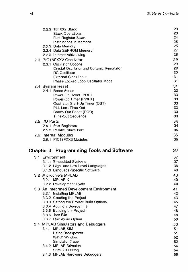
2.2.2 18FXX2 Stack 23
Stack Operations 23
Fast Register Stack 24
Instructions in Memory 25
2.2.3 Data Memory 25
2.2.4 Data EEPROM Memory 27
2.2.5 Indirect Addressing 28
2.3 PIC18FXX2 Oscillator 29
2.3.1 Oscillator Options 29
Crystal Oscillator and Ceramic Resonator 29
RC Oscillator 30
External Clock Input 31
Phase Locked Loop Oscillator Mode 31
2.4 System Reset 31
2.4.1 Reset Action 32
Power-On Reset (POR) 33
Power-Up Timer (PWRT) 33
Oscillator Start-Up Timer (OST) 33
PLL Lock Time-Out 33
Brown-Out Reset (BOR) 33
Time-Out Sequence 33
2.5 I/O Ports 34
2.5.1 Port Registers 34
2.5.2 Parallel Slave Port 35
2.6 Internal Modules 35
2.6.1 PIC18FXX2 Modules 35
Chapter 3 Programming Tools and Software 37
3.1 Environment 37
3.1.1 Embedded Systems 37
3.1.2 High-and Low-Level Languages 38
3.1.3 Language-Specific Software 40
3.2 Microchip's MPLAB 40
3.2.1 MPLAB X 40
3.2.2 Development Cycle 40
3.3 An Integrated Development Environment 41
3.3.1 Installing MPLAB 42
3.3.2 Creating the Project 43
3.3.3 Setting the Project Build Options 45
3.3.4 Adding a Source File 47
3.3.5 Building the Project 48
3.3.6 .hex File 48
3.3.7 Quickbuild Option 50
3.4 MPLAB Simulators and Debuggers 50
3.4.1 MPLAB SIM 51
Using Breakpoints 51
Watch Window 52
Simulator Trace 52
3.4.2 MPLAB Stimulus 54
Stimulus Dialog 54
3.4.3 MPLAB Hardware Debuggers 55

Table of Contents vii
3.4.4 An Improvised Debugger 56
3.5 Development Programmers 56
3.5.1 Microchip PICkit 2 and PICkit 3 58
3.5.2 Micropro USB PIC Programmer 60
3.5.3 MPLAB ICD 2 and ICD 3 In-Circuit Debuggers/Programmers 60
3.6 Test Circuits and Development Boards 61
3.6.1 Commercial Development Boards 61
3.6.2 Circuit Prototype 63
3.6.3 Breadboard 64
Limitations of Breadboards 65
Breadboarding Tools and Techniques 66
3.6.4 Wire Wrapping 67
3.6.5 Perfboards 67
3.6.6 Printed Circuit Boards 68
Chapter 4 Assembly Language Program 71
4.1 Assembly Language Code 71
4.1.1 A Coding Template 71
Program Header 73
Program Environment Directives 73
Configuration Bits 73
Error Message Level Control 74
Variables and Constants 74
Code Area and Interrupts 74
4.1.2 Programming Style 74
Source File Comments 75
4.2 Defining Data Elements 75
4.2.1 equ Directive 76
4.2.2 cblock Directive 76
4.2.3 Access to Banked Memory 77
4.3 Naming Conventions 77
4.3.1 Register and Bit Names 77
4.4 PIC 18Fxx2 Instruction Set 79
4.4.1 Byte-Oriented Instructions 80
4.4.2 Bit-Oriented Instructions 80
4.4.3 Literal Instructions 80
4.4.4 Control Instructions 80
Chapter 5 PIC18 Programming in C Language 85
5.1 C Compilers 85
5.1.1 C versus Assembly Language 85
5.1.2 MPLAB C18 86
5.2 MPLAB C18 Installation 86
5.2.1 MPLAB Software Components 87
5.2.2 Configuration Options 88
5.2.3 System Requirements 89
5.2.4 Execution Flow 90
5.3 C Compiler Project 91
5.3.1 Creating the Project 91

viii Table of Contents
Select Hardware Device 92
Select the Language Toolsuite 92
Create a New Project 93
Add Files to the Project 95
5.3.2 Selecting the Build Directory 96
5.4 A First Program in C 98
5.4.1 Source Code Analysis 99
main() Function 100
Local Functions 101
Chapter 6 C Language in an Embedded Environment 103
6.1 MPLAB C18 System 103
6.1.1 PIC18 Extended Mode 104
6.2 MPLAB C18 Libraries 104
6.2.1 Start-Up Routines 104
6.2.2 Online Help for C18 and Libraries 105
6.3 Processor-Independent Libraries 106
6.3.1 General Software Library 106
Character Classification Functions 107
Data Conversion Functions 107
Memory and String Manipulation Functions 108
Delay Functions 110
Reset Functions 111
Character Output Functions 112
6.4 Processor-Specific Libraries 115
6.4.1 Hardware Peripheral Library Functions 115
6.4.2 Software Peripherals Library Functions 116
6.4.3 Macros for Inline Assembly 116
6.4.4 Processor-Specific Header Files 117
6.5 Math Libraries 118
6.5.1 ANSI-IEEE 754 Binary Floating-Point Standard 118
Encodings 119
Rounding 119
6.5.2 Standard Math Library Functions 120
6.5.3 Floating-Point Math Sample Program 120
6.6 C18 Language Specifics 122
6.6.1 C18 Integer Data Types 122
6.6.2 C18 Floating-Point Data Types 122
6.6.3 Endianness 123
6.6.4 Storage Classes 123
6.6.5 Static Function Argument 123
6.6.6 Storage Qualifiers 123
far and near Qualifiers 123
rom and ram Qualifiers 124
Chapter 7 Programming Simple Input and Output 125
7.1 Port-Connected I/O 125
7.1.1 A Simple Circuit and Code 125
7.1.2 Circuit Schematics 125
7.1.3 Assembler Simple I/O Program 126

Table ofContents ix
7.1.4 Assembler Source Code Analysis 129
Command Monitoring Loop 129
Action on the LEDs 130
A Delay Routine 130
7.2 C Language Simple I/O Program 131
7.2.1 C Source Code Analysis 132
main() Function 133
7.3 Seven-Segment LED Programming 134
7.3.1 Computed Goto 135
7.3.2 Assembler Seven-Segment LED Program 136
Access Bank Operation 136
Port A for Digital Operation 137
DIP Switch Processing 138
Seven-Segment Code with Computed Goto 139
7.3.3 Assembler Table Lookup Sample Program 140
7.4 C Language Seven-Segment LED Programs 141
7.4.1 Code Selection by Switch Construct 142
7.4.2 Code Selection by Table Lookup 142
7.5 A Demonstration Board 143
7.6.1 Power Supply 145
Voltage Regulator 145
Chapter 8 Interrupts 147
8.1 Interrupt Mechanism 147
8.2 PIC18 Interrupt System 147
8.2.1 Hardware Sources 148
8.2.2 Interrupt Control and Status Registers 148
INTCON Registers 149
PIE Registers 151
PIR Registers 152
IPR Registers 152
8.2.3 Interrupt Priorities 154
High-Priority Interrupts 154
Low-Priority Interrupts 155
An Interrupt Interrupting Another One 155
8.2.4 Context Saving Operations 155
Context Saving during Low-Priority Interrupts 156
8.3 Port B Interrupts 157
8.3.1 Port B External Interrupt 158
8.3.2 INTO Interrupt Demo Program 158
cblock Directive 158
Vectoring the Interrupt 159
Initialization 160
Setup INTO 160
Program Foreground 161
Interrupt Service Routine 161
Switch Debouncing 162
Interrupt Action 162
8.3.3 Port B Line Change Interrupt 163
Reentrant Interrupts 164
Multiple External Interrupts 165

X Table of Contents
8.3.4 Port B Line Change Interrupt Demo Program 165
Setting Up the Line Change Interrupt 165
Interrupt Service Routine 166
8.4 Sleep Mode and Interrupts 168
8.4.1 Wake-Up from SLEEP 169
8.4.2 Sleep_Demo Program 170
8.5 Interrupt Programming in C Language 171
8.5.1 Interrupt Action 171
Context in the Stack 172
Interrupt Data 172
8.5.2 Interrupt Programming in C18 173
Sleep Mode and RBO Interrupt Demo Program 174
Port B Interrupt on Change Demo Program 176
Chapter 9 Delays, Counters, and Timers 179
9.1 PIC18 Family Timers 179
9.2 Delay Timers 179
9.2.1 Power-Up Timer (PWRT) 179
9.2.2 Oscillator Start-Up Timer (OST) 180
9.2.3 Phase Locked Loop (PLL) 180
Power-Up Delay Summary 181
9.2.4 Watchdog Timer 181
Watchdog Timer Uses 181
9.3 Hardware Timer-Counters 182
9.4 TimerO Module 182
9.4.1 TimerO Architecture 184
16-bit Mode Operation 184
Timer and Counter Modes 185
TimerO Interrupt 185
External Clock Source 185
TimerO Prescaler 186
9.4.2 TimerO as a Delay Timer 186
Long Delay Loops 187
Delay Accuracy Issues 188
Black-Ammerman Method 188
Delays with 16-Bit TimerO 189
9.4.3 Counter and Timer Programming 189
Programming a Counter 190
TimerO_as_Counter.asm Program 190
A Timer/Counter Test Circuit 191
TimerO _Delay.asm Program 191
A Variable Time-Lapse Routine 193
TimerO_VarDelay.asm Program 193
Interrupt-Driven Timer 196
9.5 Other Timer Modules 199
9.5.1 Timerl Module 199
TimeM in Timer Mode 200
Timerl in Synchronized Counter Mode 201
External Clock Input Timing in Synchronized Mode 201
Timerl Read and Write Operations 201
16-bit Mode Timerl Write 201

Table of Contents xi
16-Bit Read-Modify-Write 202
Reading and Writing Timed in Two 8-bit Operations 2029.5.2 Timer2 Module
203Timer Clock Source 204TMR2 and PR2 Registers 204Prescaler and Postscaler 205Timer2 Initialization
205
9.5.3 Timer3 Module205
Timer3 in Timer Mode 207Timer3 in Synchronized Counter Mode 207External Clock Input Timing 208
Timer3 in Asynchronous Counter Mode 208External Clock Input Timing with Unsynchronized Clock 208Timer3 Reading and Writing 208Writing in 16-Bit Mode 20816-bit Read-Modify-Write Operation 209Reading in Asynchronous Counter Mode 209Timerl Oscillator in Timer3 210
9.6 C-18 Timer Functions 2109.6.1 CloseTimerx Function 2109.6.2 OpenTimerx Function 2119.6.3 ReadTimerx Function
2119.6.4 WriteTimerx Function 212
9.7 Sample Programs 2129.7.1 TimerO_as_Counter program 2129.7.2 Timer0_Delay Program 2159.7.3 TimerO_VarDelay Program 2169.7.4 Timer0_Varlnt Program 2209.7.5 C_Timer_Show Program 224
Chapter 10 Data EEPROM 227
10.1 EEPROM on the PIC18 Microcontrollers 22710.1.2 On-Board Data EEPROM 227
10.2 EEPROM Programming 22810.2.1 Reading EEPROM Data 22810.2.2 Writing EEPROM Data 230
10.3 Data EEPROM Programming in C Language 23110.3.1 EEPROM Library Functions 23210.3.2 Sample Code 232
10.4 EEPROM Demonstration Programs 23310.4.1 EEPROM_to_7Seg Program 23310.4.2 C_EEPROM_Demo Program 237
Chapter 11 Liquid Crystal Displays 239
11.1 LCD239
11.1.1 LCD Features and Architecture 23911.1.2 LCD Functions and Components 240
Internal Registers 240Busy Flag 240Address Counter
240

xii Table of Contents
Display Data RAM (DDRAM) 240
Character Generator ROM (CGROM) 241
Character Generator RAM (CGRAM) 241
Timing Generation Circuit 241
Liquid Crystal Display Driver Circuit 242
Cursor/Blink Control Circuit 242
11.1.3 Connectivity and Pin Out 242
11.2 Interfacing with the HD44780 243
11.2.1 Busy Flag and Timed Delay Options 244
11.2.2 Contrast Control 245
11.2.3 Display Backlight 245
11.2.4 Display Memory Mapping 245
11.3 The HD44780 Instruction Set 247
11.3.1 Instruction Set Overview 247
Clearing the Display 248
Return Home 248
Entry Mode Set 248
Display and Cursor ON/OFF 248
Cursor/Display Shift 248
Function Set 248
Set CGRAM Address 249
Set DDRAM Address 249
Read Busy Flag and Address Register 249
Write data 249
Read data 250
11.3.2 18F452 8-Bit Data Mode Circuit 250
11.4 LCD Programming 251
11.4.1 Defining Constants and Variables 252
Constants 252
11.4.2 Using MPLAB Data Directives 253
Data Definition in Absolute Mode 253
Relocatable Code 254
Issues with Initialized Data 254
11.4.3 LCD Initialization 255
Reset Function 255
Initialization Commands 256
Function Preset Command 256
Function Set Command 256
Display Off 257
Display and Cursor On 257
Set Entry Mode 258
Cursor and Display Shift 258
Clear Display 258
11.4.4 Auxiliary Operations 259
Time Delay Routine 259
Pulsing the E Line 260
Reading the Busy Flag 261
Bit Merging Operations 262
11.4.5 Text Data Storage and Display 264
Generating and Storing a Text String 265
Data in Program Memory 265
Displaying the Text String 266
Sample Program LCD_18F_MsgFlag 268

Table of Contents xiii
11.5 Data Compression Techniques 278
11.5.1 4-Bit Data Transfer Mode 279
11.5.2 Preserving Port Data 279
11.5.3 Master/Slave Systems 280
11.5.4 4-Bit LCD Interface Sample Programs 281
11.6 LCD Programming in C18 291
11.6.1 Editing xlcd.h 292
Defining the Interface 292
Defining the Data Port and Tris Register 293
11.6.2 Timing Routines 294
11.6.3 XLCD Library Functions 295
BusyXLCD 295
OpenXLCD 296
putrXLCD 296
putsXLCD 296
ReadAddr 296
ReadDataXLCD 297
SetDDRamAddr 297
SetCGRamAddr 297
WriteCmdXLCD 298
WriteDataXLCD 298
11.7 LCD Application Development in C18 299
11.7.1 Using the Project Wizard 299
Main Program File 300
Chapter 12 Real-Time Clocks 303
12.1 Measuring Time 303
12.1.1 Clock Signal Source 303
32 kHz Crystal Circuit 304
12.1.2 Programming the Timerl Clock 305
Setting Up Timerl Hardware 305
Coding the Interrupt Handler 306
Sample Program RTC_18F_Timer1 .asm 306
12.2 Real-Time Clock ICs 309
12.2.1 NJU6355 310
12.2.2 6355 Data Formatting 310
12.2.3 Initialization and Clock Primitives 311
Reading and Writing Clock Data 311
Initialize RTC 314
12.2.4 BCD Conversions 316
12.3 RTC Demonstration Circuit and Program 318
12.3.1 RTC_F18_6355.asm Program 318
Code Details 319
Code Listing 319
12.4 Real-Time Clocks in C18 336
12.4.1 Timerl-Based RTC in C18 336

xiv Table of Contents
Chapter 13 Analog Data and Devices 343
13.1 Operations on Computer Data 343
13.2 18F452 A/D Hardware 343
13.2.1 A/D Module on the 18F452 344
ADCONO Register 345
ADCON1 Register 347
SLEEP Mode Operation 348
13.2.2 A/D Module Sample Circuit and Program 349
Initialize A/D Module 350
A/D Conversion 351
13.2.3 A2D_Pot2LCD Program 352
13.3 A/D Conversion in C18 365
13.3.1 Conversion Primitives 365
Busy ADC 365
CloseADC 365
ConvertADC 366
OpenADC 366
ReadADC 367
SetChan ADC 367
13.3.2 C_ADConvert.c Program 368
C_ADConvert.c Code Listing 368
13.4 Interfacing with Analog Devices 371
13.4.1 LM 34 Temperature Sensor 371
13.4.2 LM135 Circuits 372
Calibrating the Sensor 372
13.4.3 C_ADC_LM35.c Program 373
Chapter 14 Operating Systems 377
14.1 Time-Critical Systems 377
14.1.2 Multitasking in Real-Time 378
14.2 RTOS Scope 378
14.2.1 Tasks, Priorities, and Deadlines 379
14.2.2 Executing in Real-Time 381
14.3 RTOS Programming 381
14.3.1 Foreground and Background Tasks 382
Interrupts in Tasking 382
14.3.2 Task Loops 383
14.3.3 Clock-Tick Interrupt 383
14.3.4 Interrupts in Preemptive Multitasking 383
14.4 Constructing the Scheduler 384
14.4.1 Cyclic Scheduling 384
14.4.2 Round-Robin Scheduling 385
14.4.3 Task States and Prioritized Scheduling 385
14.5 A Small System Example 386
14.5.1 Task Structure 386
14.5.2 Semaphore 387
14.6 Sample OS Application 388
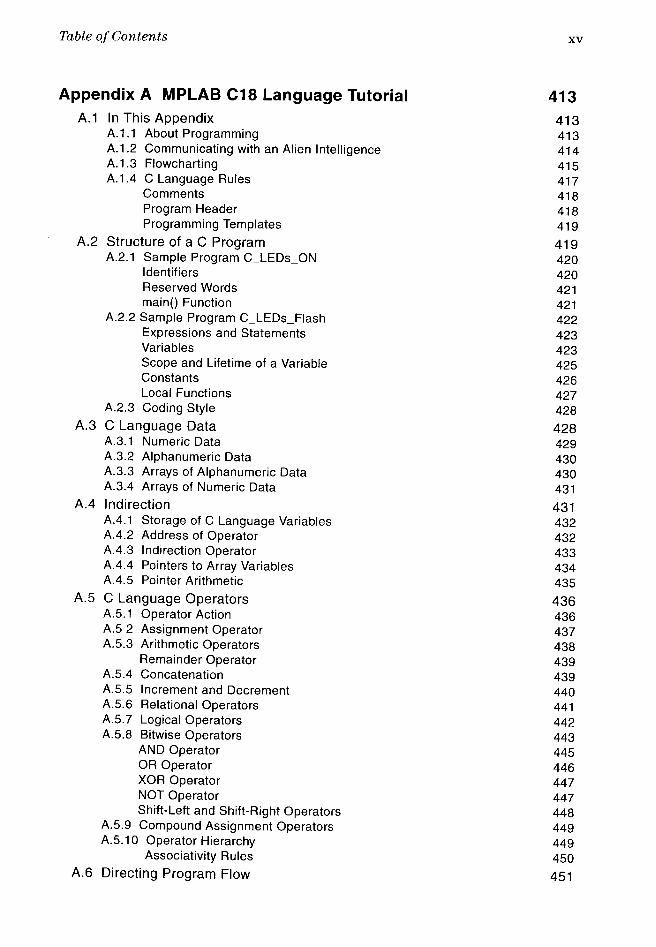
Table of Contents xv
Appendix A MPLAB C18 Language Tutorial 413
A.1 In This Appendix 413
A.1.1 About Programming 413
A.1.2 Communicating with an Alien Intelligence 414
A.1.3 Flowcharting 415
A.1.4 C Language Rules 417
Comments 418
Program Header 418
Programming Templates 419
A.2 Structure of a C Program 419
A.2.1 Sample Program C_LEDs_ON 420
Identifiers 420
Reserved Words 421
main() Function 421
A.2.2 Sample Program C_LEDs_Flash 422
Expressions and Statements 423
Variables 423
Scope and Lifetime of a Variable 425
Constants 426
Local Functions 427
A.2.3 Coding Style 428
A.3 C Language Data 428A.3.1 Numeric Data 429
A.3.2 Alphanumeric Data 430
A.3.3 Arrays of Alphanumeric Data 430
A.3.4 Arrays of Numeric Data 431
A.4 Indirection 431A.4.1 Storage of C Language Variables 432
A.4.2 Address of Operator 432
A.4.3 Indirection Operator 433
A.4.4 Pointers to Array Variables 434
A.4.5 Pointer Arithmetic 435
A.5 C Language Operators 436
A.5.1 Operator Action 436
A.5 2 Assignment Operator 437
A.5.3 Arithmetic Operators 438
Remainder Operator 439
A.5.4 Concatenation 439
A.5.5 Increment and Decrement 440
A.5.6 Relational Operators 441
A.5.7 Logical Operators 442
A.5.8 Bitwise Operators 443
AND Operator 445
OR Operator 446
XOR Operator 447
NOT Operator 447
Shift-Left and Shift-Right Operators 448
A.5.9 Compound Assignment Operators 449
A.5.10 Operator Hierarchy 449
Associativity Rules 450
A.6 Directing Program Flow 451

xvi Table of Contents
A.6.1 Decisions Constructs 451
if Construct 451
Statement Blocks 452
Nested if Construct 452
else Construct 454
Dangling else Case 454
else-if Clause 456
switch Construct 457
Conditional Expressions 460
A.7 Loops and Program Flow Control 460
A.7.1 Loops and Iterations 461
A.7.2 Elements of a Program Loop 461
A.7.3 for Loop 462
Compound Statement in Loops 464
while Loop 464
do-while Loop 465
A.8 Breaking the Flow 466
A.8.1 goto Statement 466
A.8.2 break Statement 467
A.8.3 continue Statement 468
A.9 Functions and Structured Programming 469
A.9.1 Modular Construction 469
A.9.2 Structure of a Function 470
Function Prototype 470
Function Definition 471
Function Call 471
Return Keyword 472
Matching Arguments and Parameters 473
A.10 Visibility of Function Arguments 474
A. 10.1 Using External Variables 474
A. 10.2 Passing Data by Reference 475
Pointers and Functions 475
Passing Array Variables 476
A.10.3 Function-Like Macros 477
Macro Argument 477
A.11 Structures, Bit Fields, and Unions 478
A.11.1 Structure Declaration 478
Structure Type Declaration 479
Structure Variable Declaration 479
A.11.2 Accessing Structure Elements 480
Initializing Structure Variables 481
Manipulating a Bit Field 482
Type Casting 484
A.11.3 Unions 484
A.11.4 Structures and Functions 485
Pointers to Structures 485
Pointer Member Operator 485
Passing Structures to Functions 486
A.11.5 Structures and Unions in MPLAB C18 487

Table of Contents xvii
Appendix B Debugging 18F Devices 491
B.1 Art of Debugging 491
B.1.1 Preliminary Debugging 492
B.1.2 Debugging the Logic 492
B.2 Software Debugging 493
B.2.1 Debugger-Less Debugging 493
B.2.2 Code Image Debugging 493
B.2.3 MPLAB SIM Features 494
Run Mode 494
Step Mode 494
Animate 494
Mode Differences 494
Build Configurations 495
Setting Breakpoints 495
B.2.4 PIC 18 Special Simulations 495
Reset Conditions 495
Sleep 495
Watchdog Timer 496
Special Registers 496
B.2.5 PIC 18 Peripherals 496
B.2.6 MPLAB SIM Controls 497
B.2.7 Viewing Commands 498
Dissasembly Listing 498
File Registers 499
Hardware Stack 500
Locals 500
Program Memory 500
Special Function Registers 501
Watch 502
Watch Window in C Language 504
B.2.8 Simulator and Tracing 504
Setting Up a Trace 505
Trace Menu 506
B.2.9 Stimulus 507
Stimulus Basics 508
Using Stimulus 509
Asynch Tab 510
Message-Based Stimulus 510
Pin/Register Actions Tab 510
Advanced Pin/Register Tab 512
Clock Stimulus Tab 513
Register Injection Tab 514
Register Trace Tab 515
B.3 Hardware Debugging 516
B.3.1 Microchip Hardware Programmers/Debuggers 516
MPLAB ICD2 516
MPLAB ICD3 517
MPLAB ICE 2000 517
MPLAB ICE 4000 518
MPLAB REAL ICE 519
MPLAB PICkit 2 and PICkit 3 519
B.3.2 Using Hardware Debuggers 519

xviii Table of Contents
Which Hardware Debugger? 520
ICSP 520
B.3.3 MPLAB ICD2 Debugger Connectivity 521
Connection from Module to Target 522
Debug Mode Requirements 523
Debug Mode Preparation 523
Debug Ready State 524
Breadboard Debugging 525
B.4 MPLAB ICD 2 Tutorial 526
B.4.1 Circuit Hardware 526
B.4.2 LedFlash_Reloc Program 527
B.4.3 Relocatable Code 527
Header Files 527
Program Memory 527
Configuration Requirements 528
RAM Allocations 528
LedFlash_Reloc.asm Program 529
B.4.4 Debugging Session 531
Appendix C Building Your Own Circuit Boards 533
C. 1 Drawing the Circuit Diagram 533
C.2 Printing the PCB Diagram 535
C.3 Transferring the PCB Image 535
C.4 Etching the Board 536
C.5 Finishing the Board 536
C.6 Backside Image 536
Appendix D PIC18 Instruction Set 539
Appendix E Number Systems and Data Encoding 633
E.1 Decimal and Binary Systems 633
E.1.1 Binary Number System 633
E.1.2 Radix or Base of a Number System 634
E.2 Decimal versus Binary Numbers 634E.2.1 Hexadecimal and Octal 635
E.3 Character Representations 636
E.3.1 ASCII 636
E.3.2 EBCDIC and IBM 638
E.3.3 Unicode 639
E.4 Encoding of Integers 639E.4.1 Word Size 640
E.4.2 Byte Ordering 641
E.4.3 Sign-Magnitude Representation 642
E.4.4 Radix Complement Representation 643
E.4.5 Simplification of Subtraction 645
E.5 Binary Encoding of Fractional Numbers 646E.5.1 Fixed-Point Representations 647
E.5.2 Floating-Point Representations 648

Table of Contents xix
E.5.3 Standardized Floating-Point 649
E.5.4 Binary-Coded Decimals (BCD) 650
E.5.5 Floating-Point BCD 650
Appendix F Basic Electronics 653
R1 Atom 654
F.2 Isotopes and Ions 654
F.3 Static Electricity 655
F.4 Electrical Charge 656
F.4.1 Voltage 656
F.4.2 Current 656
F.4.3 Power 657
F.4.4 Ohm's Law 657
F.5 Electrical Circuits 658
F.5.1 Types of Circuits 658
F.6 Circuit Elements 660
F.6.1 Resistors 661
F.6.2 Revisiting Ohm's Law 661
F.6.3 Resistors in Series and Parallel 662
F.6.4 Capacitors 664
F.6.5 Capacitors in Series and in Parallel 665
F.6.6 Inductors 666
F.6.7 Transformers 667
F.7 Semiconductors 667
F.7.1 Integrated Circuits 668
F.7.2 Semiconductor Electronics 668
F.7.3 P-Type and N-Type Silicon 669
F.7.4 Diode 669
Index 671

![APLICATION OF PIC MICROCONTROLLERS IN · PDF fileAPLICATION OF PIC MICROCONTROLLERS IN EMBEDDED SYSTEMS FOR ... D. Andrić, 2000, PIC mikrokontroleri, Mikroelektronika Beograd. [2]](https://img.pdfslide.net/doc/110x75/5a787ef67f8b9a1f128bdcae/aplication-of-pic-microcontrollers-in-of-pic-microcontrollers-in-embedded-systems.jpg)