Embed Size (px)
Citation preview
User Manual
MicroDock II
Automatic Test and Calibration Station
D5617/4 EnglishiERP: 122293
© 2006 BW Technologies. All rights reserved. Printed in Canada.
All product names are trademarks of their respective companies.
Limited Warranty & Limitation of Liability BW Technologies LP (BW) warrants this product to be free from defects in material and workmanship under normal use and service for a period of two years, beginning on the date of shipment to the buyer. This warranty extends only to the sale of new and unused products to the original buyer. BW’s warranty obligation is limited, at BW’s option, to refund of the purchase price, repair, or replacement of a defective product that is returned to a BW authorized service center within the warranty period. In no event shall BW’s liability hereunder exceed the purchase price actually paid by the buyer for the Product. This warranty does not include:
a) fuses, disposable batteries or the routine replacement of parts due to the normal wear and tear of the product arising from use; b) any product which in BW’s opinion, has been misused, altered, neglected or damaged by accident or abnormal conditions of operation, handling or use; c) any damage or defects attributable to repair of the product by any person other than an authorized dealer, or the installation of unapproved parts on the
product; or The obligations set forth in this warranty are conditional on:
a) proper storage, installation, calibration, use, maintenance and compliance with the product manual instructions and any other applicable recommendations of BW;
b) the buyer promptly notifying BW of any defect and, if required, promptly making the product available for correction. No goods shall be returned to BW until receipt by the buyer of shipping instructions from BW; and
c) the right of BW to require that the buyer provide proof of purchase such as the original invoice, bill of sale or packing slip to establish that the product is within the warranty period.
THE BUYER AGREES THAT THIS WARRANTY IS THE BUYER’S SOLE AND EXCLUSIVE REMEDY AND IS IN LIEU OF ALL OTHER WARRANTIES, EXPRESS OR IMPLIED, INCLUDING BUT NOT LIMITED TO ANY IMPLIED WARRANTY OF MERCHANTABILITY OR FITNESS FOR A PARTICULAR PURPOSE. BW SHALL NOT BE LIABLE FOR ANY SPECIAL, INDIRECT, INCIDENTAL OR CONSEQUENTIAL DAMAGES OR LOSSES, INCLUDING LOSS OF DATA, WHETHER ARISING FROM BREACH OF WARRANTY OR BASED ON CONTRACT, TORT OR RELIANCE OR ANY OTHER THEORY. Since some countries or states do not allow limitation of the term of an implied warranty, or exclusion or limitation of incidental or consequential damages, the limitations and exclusions of this warranty may not apply to every buyer. If any provision of this warranty is held invalid or unenforceable by a court of competent jurisdiction, such holding will not affect the validity or enforceability of any other provision.
BW Technologies LP BW America BW Europe 2840 – 2nd Ave. SE 3279 West Pioneer Parkway 5 Canada Close, Calgary, AB Arlington, TX Banbury, Oxfordshire Canada T2A 7X9 USA 76013 United Kingdom OX16 2RT
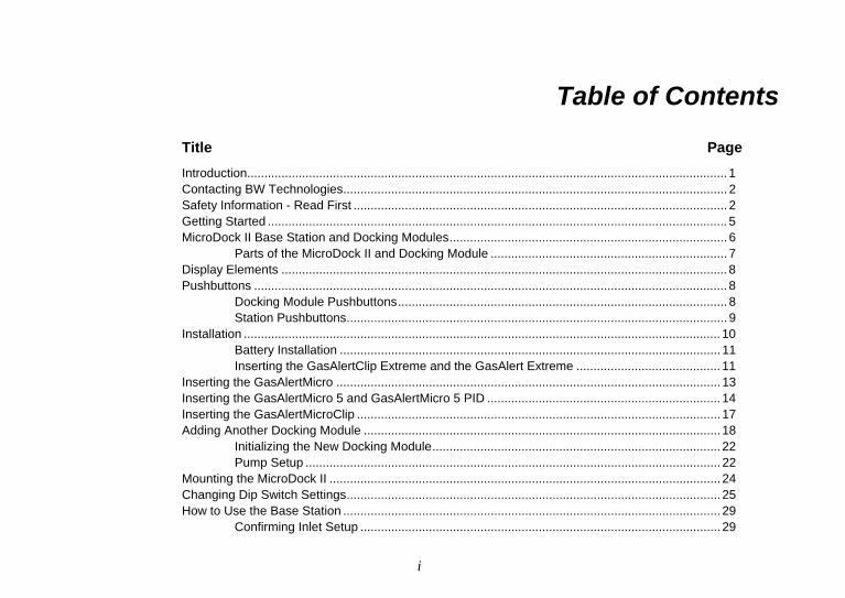
Table of Contents
Title Page Introduction............................................................................................................................................ 1 Contacting BW Technologies................................................................................................................ 2 Safety Information - Read First ............................................................................................................. 2 Getting Started ...................................................................................................................................... 5 MicroDock II Base Station and Docking Modules................................................................................. 6
Parts of the MicroDock II and Docking Module ..................................................................... 7 Display Elements .................................................................................................................................. 8 Pushbuttons .......................................................................................................................................... 8
Docking Module Pushbuttons................................................................................................ 8 Station Pushbuttons............................................................................................................... 9
Installation ........................................................................................................................................... 10 Battery Installation ............................................................................................................... 11 Inserting the GasAlertClip Extreme and the GasAlert Extreme .......................................... 11
Inserting the GasAlertMicro ................................................................................................................ 13 Inserting the GasAlertMicro 5 and GasAlertMicro 5 PID .................................................................... 14 Inserting the GasAlertMicroClip .......................................................................................................... 17 Adding Another Docking Module ........................................................................................................ 18
Initializing the New Docking Module.................................................................................... 22 Pump Setup ......................................................................................................................... 22
Mounting the MicroDock II .................................................................................................................. 24 Changing Dip Switch Settings............................................................................................................. 25 How to Use the Base Station .............................................................................................................. 29
Confirming Inlet Setup ......................................................................................................... 29
i
MicroDock II Users Manual
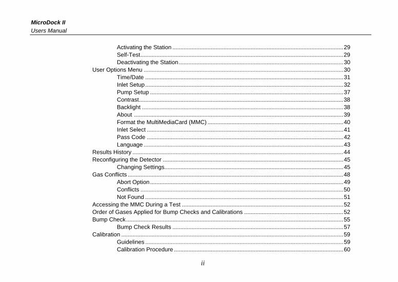
Activating the Station ...........................................................................................................29 Self-Test...............................................................................................................................29 Deactivating the Station.......................................................................................................30
User Options Menu .............................................................................................................................30 Time/Date ............................................................................................................................31 Inlet Setup............................................................................................................................32 Pump Setup .........................................................................................................................37 Contrast................................................................................................................................38 Backlight ..............................................................................................................................38 About ...................................................................................................................................39 Format the MultiMediaCard (MMC) .....................................................................................40 Inlet Select ...........................................................................................................................41 Pass Code ...........................................................................................................................42 Language .............................................................................................................................43
Results History ....................................................................................................................................44 Reconfiguring the Detector .................................................................................................................45
Changing Settings................................................................................................................45 Gas Conflicts .......................................................................................................................................48
Abort Option.........................................................................................................................49 Conflicts ...............................................................................................................................50 Not Found ............................................................................................................................51
Accessing the MMC During a Test .....................................................................................................52 Order of Gases Applied for Bump Checks and Calibrations ..............................................................52 Bump Check........................................................................................................................................55
Bump Check Results ...........................................................................................................57 Calibration ...........................................................................................................................................59
Guidelines ............................................................................................................................59 Calibration Procedure ..........................................................................................................60
ii
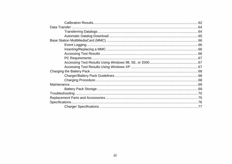
Calibration Results............................................................................................................... 62 Data Transfer ...................................................................................................................................... 64
Transferring Datalogs .......................................................................................................... 64 Automatic Datalog Download .............................................................................................. 65
Base Station MultiMediaCard (MMC) ................................................................................................. 66 Event Logging...................................................................................................................... 66 Inserting/Replacing a MMC ................................................................................................. 66 Accessing Test Results ....................................................................................................... 66 PC Requirements ................................................................................................................ 67 Accessing Test Results Using Windows 98, SE, or 2000 ................................................... 67 Accessing Test Results Using Windows XP ....................................................................... 67
Charging the Battery Pack .................................................................................................................. 68 Charger/Battery Pack Guidelines ........................................................................................ 68 Charging Procedure............................................................................................................. 68
Maintenance........................................................................................................................................ 69 Battery Pack Storage........................................................................................................... 69
Troubleshooting .................................................................................................................................. 70 Replacement Parts and Accessories.................................................................................................. 75 Specifications ...................................................................................................................................... 76
Charger Specifications ........................................................................................................ 77
iii

MicroDock II Users Manual
iv
List of Tables
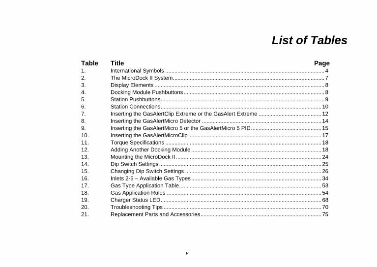
Table Title Page 1. International Symbols ........................................................................................................ 4 2. The MicroDock II System................................................................................................... 7 3. Display Elements ............................................................................................................... 8 4. Docking Module Pushbuttons............................................................................................ 8 5. Station Pushbuttons........................................................................................................... 9 6. Station Connections......................................................................................................... 10 7. Inserting the GasAlertClip Extreme or the GasAlert Extreme ......................................... 12 8. Inserting the GasAlertMicro Detector .............................................................................. 14 9. Inserting the GasAlertMicro 5 or the GasAlertMicro 5 PID.............................................. 15 10. Inserting the GasAlertMicroClip ....................................................................................... 17 11. Torque Specifications ...................................................................................................... 18 12. Adding Another Docking Module ..................................................................................... 18 13. Mounting the MicroDock II ............................................................................................... 24 14. Dip Switch Settings .......................................................................................................... 25 15. Changing Dip Switch Settings ......................................................................................... 26 16. Inlets 2-5 – Available Gas Types..................................................................................... 34 17. Gas Type Application Table............................................................................................. 53 18. Gas Application Rules ..................................................................................................... 54 19. Charger Status LED......................................................................................................... 68 20. Troubleshooting Tips ....................................................................................................... 70 21. Replacement Parts and Accessories............................................................................... 75
v

MicroDock II Users Manual
vi
List of Figures
Figure Title Page
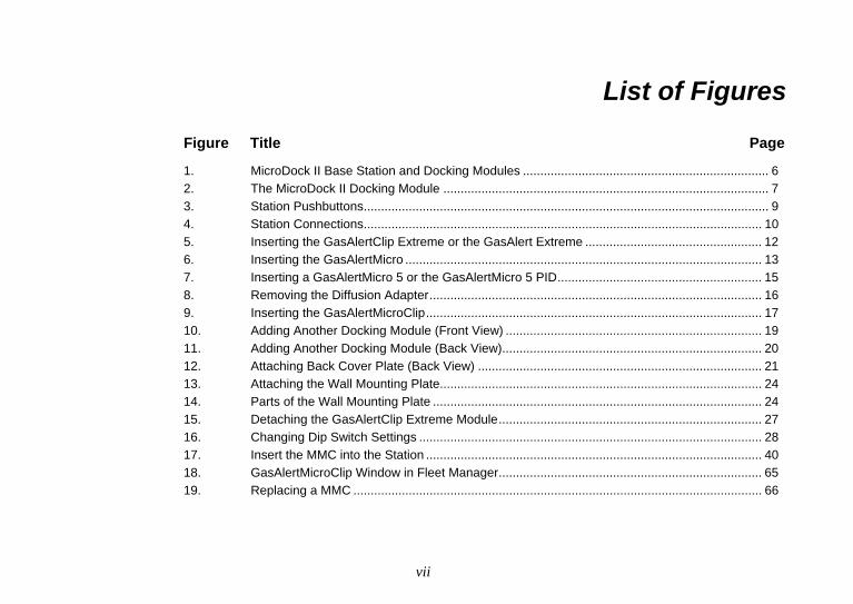
1. MicroDock II Base Station and Docking Modules ....................................................................... 6 2. The MicroDock II Docking Module .............................................................................................. 7 3. Station Pushbuttons..................................................................................................................... 9 4. Station Connections................................................................................................................... 10 5. Inserting the GasAlertClip Extreme or the GasAlert Extreme ................................................... 12 6. Inserting the GasAlertMicro ....................................................................................................... 13 7. Inserting a GasAlertMicro 5 or the GasAlertMicro 5 PID........................................................... 15 8. Removing the Diffusion Adapter................................................................................................ 16 9. Inserting the GasAlertMicroClip................................................................................................. 17 10. Adding Another Docking Module (Front View) .......................................................................... 19 11. Adding Another Docking Module (Back View)........................................................................... 20 12. Attaching Back Cover Plate (Back View) .................................................................................. 21 13. Attaching the Wall Mounting Plate............................................................................................. 24 14. Parts of the Wall Mounting Plate ............................................................................................... 24 15. Detaching the GasAlertClip Extreme Module............................................................................ 27 16. Changing Dip Switch Settings ................................................................................................... 28 17. Insert the MMC into the Station ................................................................................................. 40 18. GasAlertMicroClip Window in Fleet Manager............................................................................ 65 19. Replacing a MMC ...................................................................................................................... 66
vii
MicroDock II Users Manual
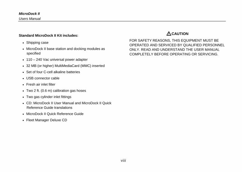
Standard MicroDock II Kit includes:
• Shipping case
• MicroDock II base station and docking modules as specified
• 110 – 240 Vac universal power adapter
• 32 MB (or higher) MultiMediaCard (MMC) inserted
• Set of four C-cell alkaline batteries
• USB connector cable
• Fresh air inlet filter
• Two 2 ft. (0.6 m) calibration gas hoses
• Two gas cylinder inlet fittings
• CD: MicroDock II User Manual and MicroDock II Quick Reference Guide translations
• MicroDock II Quick Reference Guide
• Fleet Manager Deluxe CD
aCAUTION
FOR SAFETY REASONS, THIS EQUIPMENT MUST BE OPERATED AND SERVICED BY QUALIFIED PERSONNEL ONLY. READ AND UNDERSTAND THE USER MANUAL COMPLETELY BEFORE OPERATING OR SERVICING.
viii
MicroDock II
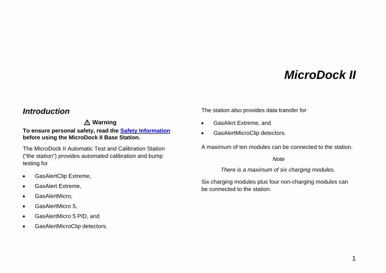
Introduction a Warning
To ensure personal safety, read the Safety Information before using the MicroDock II Base Station.
The MicroDock II Automatic Test and Calibration Station (“the station”) provides automated calibration and bump testing for
• GasAlertClip Extreme,
• GasAlert Extreme,
• GasAlertMicro,
• GasAlertMicro 5,
• GasAlertMicro 5 PID, and
• GasAlertMicroClip detectors.
The station also provides data transfer for
• GasAlert Extreme, and
• GasAlertMicroClip detectors.
A maximum of ten modules can be connected to the station.
Note
There is a maximum of six charging modules.
Six charging modules plus four non-charging modules can be connected to the station.
1
MicroDock II Users Manual
Contacting BW Technologies To contact BW Technologies, call:
USA: 1-888-749-8878 Canada: 1-800-663-4164 Europe: +44 (0) 1295 700300 Other countries:+1-403-248-9226
Address correspondence to:
BW Technologies LP 2840 – 2 Avenue S.E. Calgary, AB T2A 7X9 CANADA
Email us at: [email protected] BW Technologies’ web site at: www.gasmonitors.com
ISO 9001
Safety Information - Read First Use the station only as specified in this manual.
International symbols used on the station and in this manual are explained in Table 1.
Read the Caution statements on the following pages before using the station.
ec Note
This instrument contains batteries. Do not mix with the solid waste stream. Spent batteries should be disposed of by a qualified recycler or hazardous materials handler.
2
MicroDock II Safety Information - Read First
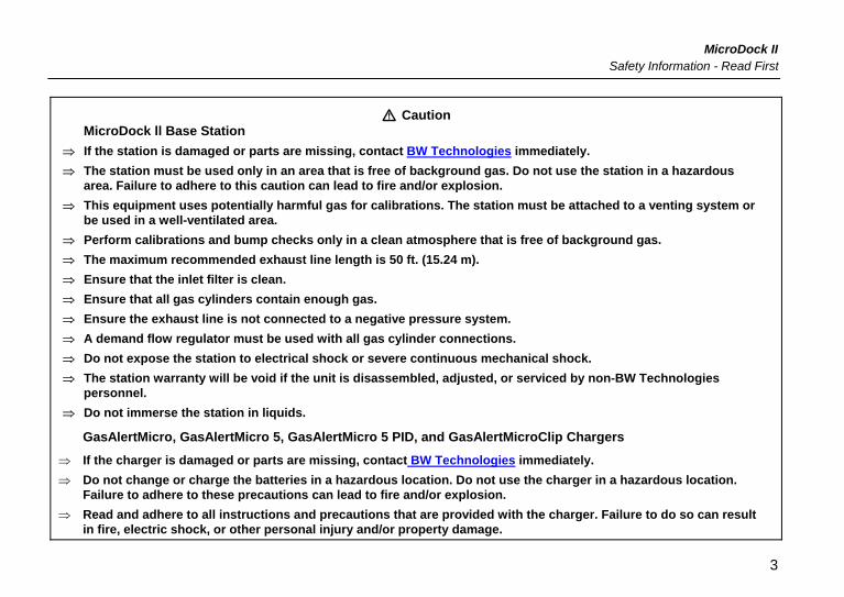
a Caution MicroDock ll Base Station
⇒ If the station is damaged or parts are missing, contact BW Technologies immediately. ⇒ The station must be used only in an area that is free of background gas. Do not use the station in a hazardous
area. Failure to adhere to this caution can lead to fire and/or explosion. ⇒ This equipment uses potentially harmful gas for calibrations. The station must be attached to a venting system or
be used in a well-ventilated area. ⇒ Perform calibrations and bump checks only in a clean atmosphere that is free of background gas. ⇒ The maximum recommended exhaust line length is 50 ft. (15.24 m). ⇒ Ensure that the inlet filter is clean. ⇒ Ensure that all gas cylinders contain enough gas. ⇒ Ensure the exhaust line is not connected to a negative pressure system. ⇒ A demand flow regulator must be used with all gas cylinder connections. ⇒ Do not expose the station to electrical shock or severe continuous mechanical shock. ⇒ The station warranty will be void if the unit is disassembled, adjusted, or serviced by non-BW Technologies
personnel. ⇒ Do not immerse the station in liquids.
GasAlertMicro, GasAlertMicro 5, GasAlertMicro 5 PID, and GasAlertMicroClip Chargers
⇒ If the charger is damaged or parts are missing, contact BW Technologies immediately. ⇒ Do not change or charge the batteries in a hazardous location. Do not use the charger in a hazardous location.
Failure to adhere to these precautions can lead to fire and/or explosion. ⇒ Read and adhere to all instructions and precautions that are provided with the charger. Failure to do so can result
in fire, electric shock, or other personal injury and/or property damage.
3
MicroDock II Users Manual
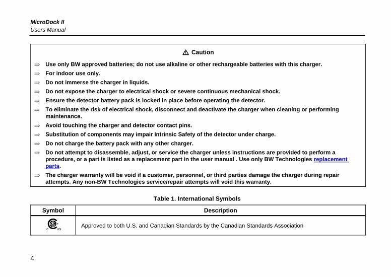
a Caution
⇒ Use only BW approved batteries; do not use alkaline or other rechargeable batteries with this charger. ⇒ For indoor use only. ⇒ Do not immerse the charger in liquids. ⇒ Do not expose the charger to electrical shock or severe continuous mechanical shock. ⇒ Ensure the detector battery pack is locked in place before operating the detector. ⇒ To eliminate the risk of electrical shock, disconnect and deactivate the charger when cleaning or performing
maintenance. ⇒ Avoid touching the charger and detector contact pins. ⇒ Substitution of components may impair Intrinsic Safety of the detector under charge. ⇒ Do not charge the battery pack with any other charger. ⇒ Do not attempt to disassemble, adjust, or service the charger unless instructions are provided to perform a
procedure, or a part is listed as a replacement part in the user manual . Use only BW Technologies replacement parts.
⇒ The charger warranty will be void if a customer, personnel, or third parties damage the charger during repair attempts. Any non-BW Technologies service/repair attempts will void this warranty.
Table 1. International Symbols
Symbol Description
n Approved to both U.S. and Canadian Standards by the Canadian Standards Association
4
MicroDock II Getting Started
Getting Started Confirm that the items below are included with the station. If the station is damaged or parts are missing, contact the place of purchase immediately.
• Batteries (four replaceable C-cell alkaline batteries)
• 32 MB (or higher) MultiMediaCard (MMC) inserted
• USB cable
• Two calibration gas hoses with quick connect fittings
• Inlet filter assembly
• Power adapter
• Charger adapter (charger models only)
• CD: MicroDock II User Manual and MicroDock II Quick Reference Guide translations
• MicroDock II Base Station Quick Reference Guide
• Fleet Manager Deluxe CD
Note
A standard MicroDock II base station is shipped with two inlets. A maximum of four calibration gas inlets can be included if specified by the user before purchasing.
To order replacement parts, refer to Replacement Parts and Accessories.
For information regarding the operations and functions of the station, refer to the following figures and tables.
• Figure 1 MicroDock II Base Station and Docking Modules
• Figure 2 and Table 2 The MicroDock ll (describes the station)
• Table 3 Display Elements (describes the station LCD icons)
• Table 4 Docking Module Pushbuttons
• Figure 3 and Table 5 Station Pushbuttons
• Figure 4 and Table 6 Station Connections
5
MicroDock II Users Manual
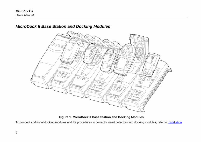
MicroDock II Base Station and Docking Modules
Figure 1. MicroDock II Base Station and Docking Modules To connect additional docking modules and for procedures to correctly insert detectors into docking modules, refer to Installation.
6
MicroDock II MicroDock II Base Station and Docking Modules
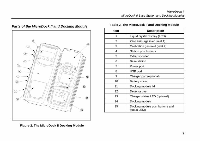
Parts of the MicroDock II and Docking Module
Figure 2. The MicroDock II Docking Module
Table 2. The MicroDock II and Docking Module
Item Description 1 Liquid crystal display (LCD)
2 Zero air/purge inlet (inlet 1)
3 Calibration gas inlet (inlet 2)
4 Station pushbuttons
5 Exhaust outlet
6 Base station
7 Power port
8 USB port
9 Charger port (optional)
10 Battery cover
11 Docking module lid
12 Detector bay
13 Charger status LED (optional)
14 Docking module
15 Docking module pushbuttons and status LEDs
7
MicroDock II Users Manual
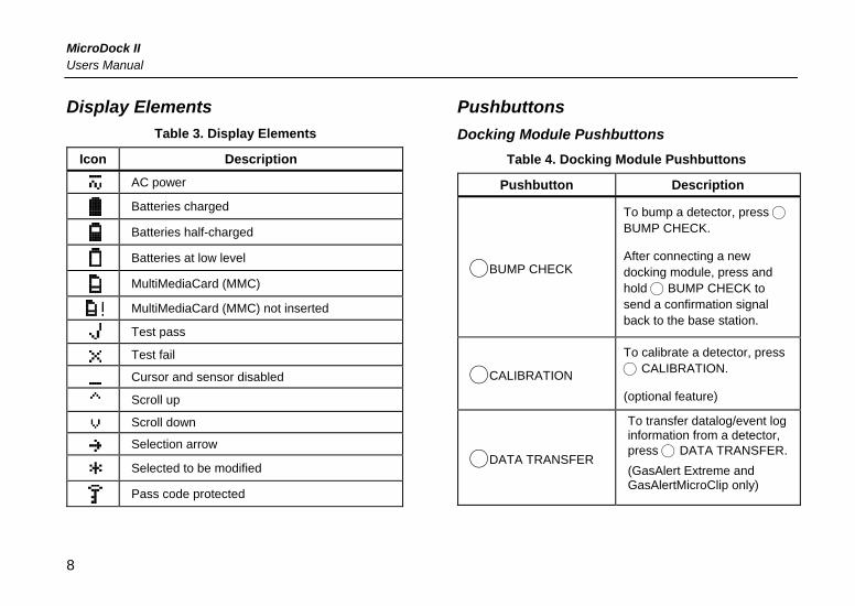
Display Elements Table 3. Display Elements
Icon Description
AC power
Batteries charged
Batteries half-charged
Batteries at low level
MultiMediaCard (MMC)
MultiMediaCard (MMC) not inserted
Test pass
Test fail
Cursor and sensor disabled
Scroll up
Scroll down
Selection arrow
Selected to be modified
Pass code protected
Pushbuttons Docking Module Pushbuttons
Table 4. Docking Module Pushbuttons
Pushbutton Description
CBUMP CHECK
To bump a detector, press C
BUMP CHECK.
After connecting a new docking module, press and hold C BUMP CHECK to send a confirmation signal back to the base station.
CCALIBRATION
To calibrate a detector, press C CALIBRATION.
(optional feature)
CDATA TRANSFER
To transfer datalog/event log information from a detector, press C DATA TRANSFER. (GasAlert Extreme and GasAlertMicroClip only)
8
MicroDock II Pushbuttons
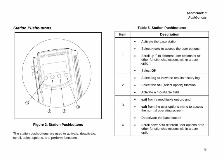
Station Pushbuttons
Figure 3. Station Pushbuttons
The station pushbuttons are used to activate, deactivate, scroll, select options, and perform functions.
Table 5. Station Pushbuttons
Item Description
1
• Activate the base station
• Select menu to access the user options
• Scroll up to different user options or to other functions/selections within a user option
• Select OK
2
• Select log to view the results history log
• Select the sel (select option) function
• Activate a modifiable field
3 • exit from a modifiable option, and
• exit from the user options menu to access the normal operating screen.
4
• Deactivate the base station
• Scroll down to different user options or to other functions/selections within a user option
9
MicroDock II Users Manual
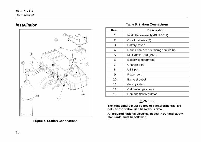
Installation
Figure 4. Station Connections
Table 6. Station Connections
Item Description 1 Inlet filter assembly (PURGE 1)
2 C-cell batteries (4)
3 Battery cover
4 Philips pan-head retaining screws (2)
5 MultiMediaCard (MMC)
6 Battery compartment
7 Charger port
8 USB port
9 Power port
10 Exhaust outlet
11 Gas cylinder
12 Calibration gas hose
13 Demand flow regulator
aWarning The atmosphere must be free of background gas. Do not use the station in a hazardous area. All required national electrical codes (NEC) and safety standards must be followed.
10
MicroDock II Installation
Note The station can operate from either an electrical power source or by using batteries. The batteries will provide automatic backup power if the main power fails.
1. Connect the power cord to the POWER port on the station and then plug the cord into an ac outlet. Or install the batteries. Refer to Battery Installation.
2. Connect the charger cord to the CHARGER port on the station and then plug the cord into an ac outlet (if applicable).
3. Attach all gas connections. Inlet 1 (PURGE) is configured for ambient air and inlets 2 - 5 are configured for calibration/test gases. Refer to Confirming Inlet Setup.
4. A demand flow regulator must be used with all gas cylinder connections.
5. Ensure the exhaust line is not connected to a negative pressure system.
For ac main installation, a circuit breaker must be integrated in the building installation as a disconnect device for the station.
The disconnect device must be installed in close proximity to the station and must be marked as a disconnecting method for the station.
Battery Installation aWarning
Only change batteries in an atmosphere that is clear of hazardous gas. Failure to adhere to this warning can result in personal injury and/or property damage.
To install batteries into the station, refer to Figure 4 and complete the following:
1. Loosen only; do not remove the retaining screws from the battery cover.
2. Remove the battery cover and set it aside. 3. Insert four C-cell batteries into the battery
compartment. 4. Replace the battery cover and tighten the retaining
screws. Do not over tighten the screws. Refer to Table 11. Torque Specifications.
Inserting the GasAlertClip Extreme and the GasAlert Extreme
aCaution Infrared or intense ambient light (sun or halogen) may interfere with the station/detector communication.
11
MicroDock II Users Manual
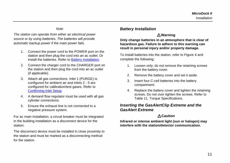
Figure 5. Inserting the GasAlertClip Extreme and the GasAlert Extreme
Table 7. Inserting the GasAlertClip Extreme and the GasAlert Extreme
Item Description
1 Alligator clip
2 Docking module lid
3 Release tabs
4 Detector bay
1. Activate the detector and wait until it is in normal operating mode.
2. Ensure the alligator clip is closed and the ring is resting flat to prevent disruptions with the transmission.
3. Press the two release tabs on the docking module and raise the lid.
4. Lower the detector (LCD face down) into the detector bay. Push forward to ensure the top of the detector connects with the top of the bay.
5. Lower the lid and press down until the release tabs click.
12
MicroDock II Inserting the GasAlertMicro
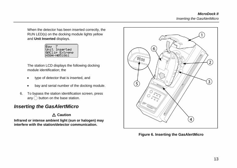
When the detector has been inserted correctly, the RUN LED(s) on the docking module lights yellow and Unit Inserted displays.
The station LCD displays the following docking module identification; the
• type of detector that is inserted, and
• bay and serial number of the docking module.
6. To bypass the station identification screen, press any C button on the base station.
Inserting the GasAlertMicro a Caution
Infrared or intense ambient light (sun or halogen) may interfere with the station/detector communication.
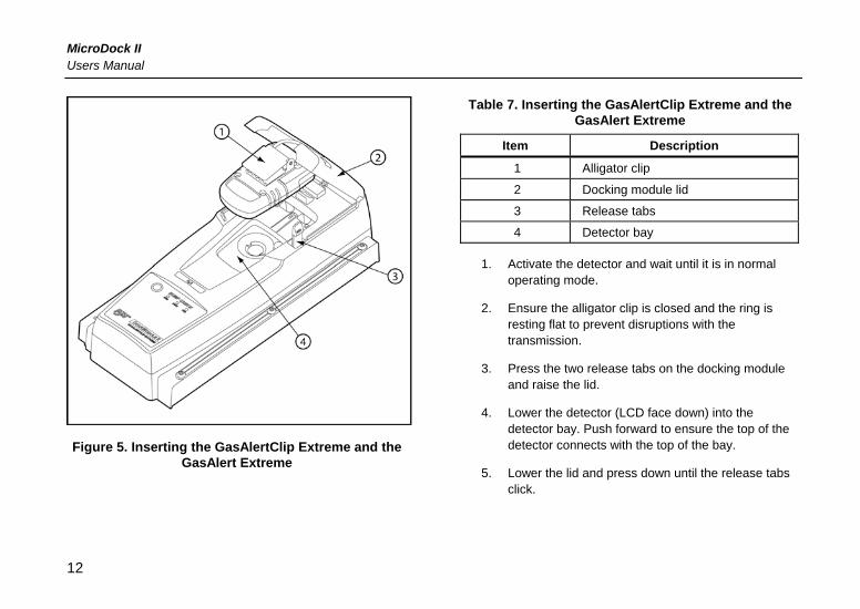
Figure 6. Inserting the GasAlertMicro
13
MicroDock II Users Manual
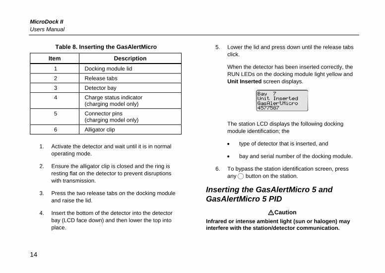
Table 8. Inserting the GasAlertMicro
Item Description 1 Docking module lid
2 Release tabs
3 Detector bay
4 Charge status indicator (charging model only)
5 Connector pins (charging model only)
6 Alligator clip
1. Activate the detector and wait until it is in normal operating mode.
2. Ensure the alligator clip is closed and the ring is resting flat on the detector to prevent disruptions with transmission.
3. Press the two release tabs on the docking module and raise the lid.
4. Insert the bottom of the detector into the detector bay (LCD face down) and then lower the top into place.
5. Lower the lid and press down until the release tabs click.
When the detector has been inserted correctly, the RUN LEDs on the docking module light yellow and Unit Inserted screen displays.
The station LCD displays the following docking module identification; the
• type of detector that is inserted, and
• bay and serial number of the docking module.
6. To bypass the station identification screen, press any C button on the station.
Inserting the GasAlertMicro 5 and GasAlertMicro 5 PID
aCaution Infrared or intense ambient light (sun or halogen) may interfere with the station/detector communication.
14
MicroDock II Inserting the GasAlertMicro 5 and GasAlertMicro 5 PID
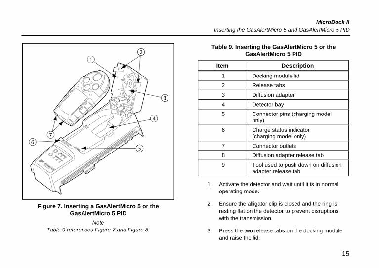
Figure 7. Inserting a GasAlertMicro 5 or the
GasAlertMicro 5 PID Note
Table 9 references Figure 7 and Figure 8.
Table 9. Inserting the GasAlertMicro 5 or the GasAlertMicro 5 PID
Item Description 1 Docking module lid
2 Release tabs
3 Diffusion adapter
4 Detector bay
5 Connector pins (charging model only)
6 Charge status indicator (charging model only)
7 Connector outlets
8 Diffusion adapter release tab
9 Tool used to push down on diffusion adapter release tab
1. Activate the detector and wait until it is in normal operating mode.
2. Ensure the alligator clip is closed and the ring is resting flat on the detector to prevent disruptions with the transmission.
3. Press the two release tabs on the docking module and raise the lid.
15
MicroDock II Users Manual
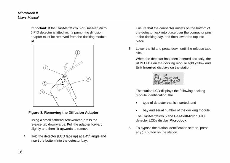
Important: If the GasAlertMicro 5 or GasAlertMicro 5 PID detector is fitted with a pump, the diffusion adapter must be removed from the docking module lid.
Figure 8. Removing the Diffusion Adapter
Using a small flathead screwdriver, press the release tab downwards. Pull the adapter forward slightly and then lift upwards to remove.
4. Hold the detector (LCD face up) at a 45o angle and insert the bottom into the detector bay.
Ensure that the connector outlets on the bottom of the detector lock into place over the connector pins in the docking bay, and then lower the top into place.
5. Lower the lid and press down until the release tabs click.
When the detector has been inserted correctly, the RUN LEDs on the docking module light yellow and Unit Inserted displays on the station.
The station LCD displays the following docking module identification; the
• type of detector that is inserted, and
• bay and serial number of the docking module.
The GasAlertMicro 5 and GasAlertMicro 5 PID detector LCDs display Microdock.
6. To bypass the station identification screen, press any C button on the station.
16
MicroDock II Inserting the GasAlertMicroClip
Inserting the GasAlertMicroClip a Caution
Infrared or intense ambient light (sun or halogen) may interfere with the station/detector communication.
Figure 9. Inserting the GasAlertMicroClip
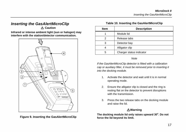
Table 10. Inserting the GasAlertMicroClip
Item Description 1 Module lid
2 Release tabs
3 Detector bay
4 Alligator clip
5 Charger status indicator
Note
If the GasAlertMicroClip detector is fitted with a calibration cap or auxiliary filter, it must be removed prior to inserting it into the docking module.
1. Activate the detector and wait until it is in normal operating mode.
2. Ensure the alligator clip is closed and the ring is resting flat on the detector to prevent disruptions with the transmission.
3. Press the two release tabs on the docking module and raise the lid.
aWarning The docking module lid only raises upward 30o. Do not force the lid beyond its limit.
17
MicroDock II Users Manual
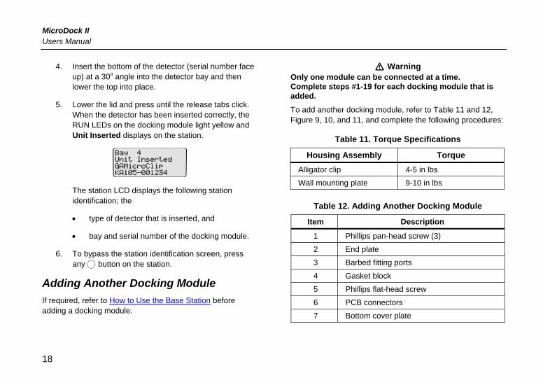
4. Insert the bottom of the detector (serial number face up) at a 30o angle into the detector bay and then lower the top into place.
5. Lower the lid and press until the release tabs click. When the detector has been inserted correctly, the RUN LEDs on the docking module light yellow and Unit Inserted displays on the station.
The station LCD displays the following station identification; the
• type of detector that is inserted, and
• bay and serial number of the docking module.
6. To bypass the station identification screen, press any C button on the station.
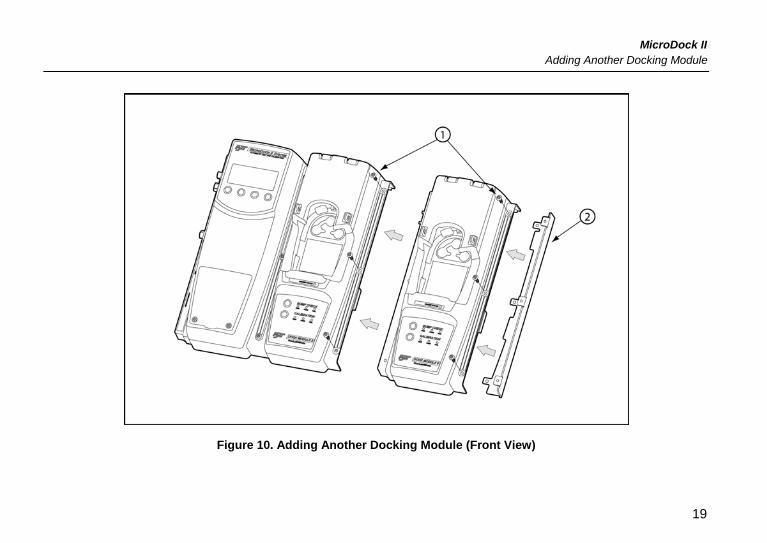
Adding Another Docking Module If required, refer to How to Use the Base Station before adding a docking module.
a Warning Only one module can be connected at a time. Complete steps #1-19 for each docking module that is added. To add another docking module, refer to Table 11 and 12, Figure 9, 10, and 11, and complete the following procedures:
Table 11. Torque Specifications
Housing Assembly Torque Alligator clip 4-5 in lbs
Wall mounting plate 9-10 in lbs
Table 12. Adding Another Docking Module
Item Description
1 Phillips pan-head screw (3)
2 End plate
3 Barbed fitting ports
4 Gasket block
5 Phillips flat-head screw
6 PCB connectors
7 Bottom cover plate
18
MicroDock II Adding Another Docking Module
Figure 10. Adding Another Docking Module (Front View)
19
MicroDock II Users Manual
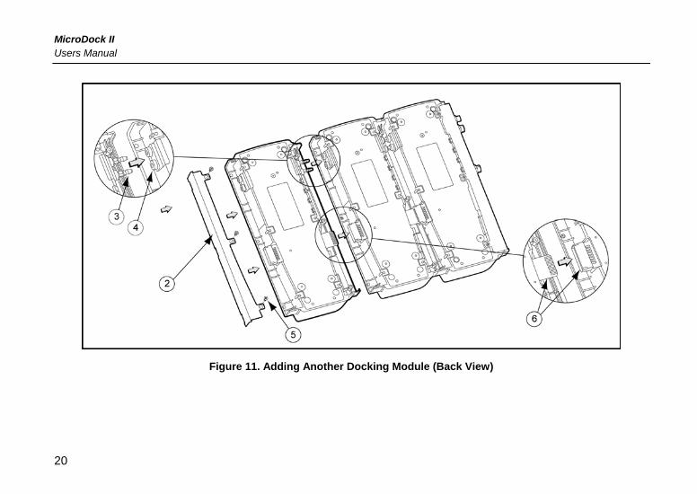
Figure 11. Adding Another Docking Module (Back View)
20
MicroDock II Adding Another Docking Module
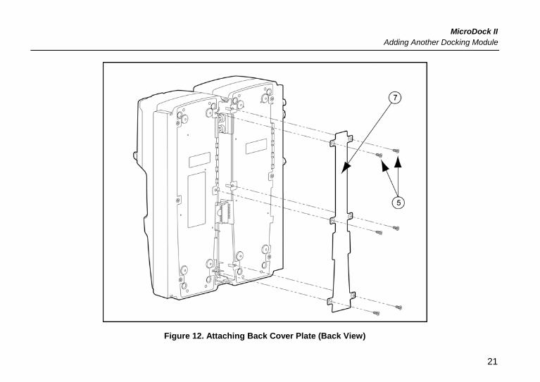
Figure 12. Attaching Back Cover Plate (Back View)
21
MicroDock II Users Manual
1. Deactivate the station.
2. Remove the power cord from the POWER port.
3. Remove the end plate. There are three Phillips screws on the front and three Philips screws on the back.
4. Attach the new docking module.
5. Ensure the barbed fitting ports mate correctly with the gasket block. Ensure that the male and female PCB connectors mate correctly.
Initializing the New Docking Module When a new docking module is connected, it must be initialized (setup to communicate with the station).
6. Activate the station.
7. Simultaneously press and hold C BUMP CHECK on the new docking module while pressing C (leftmost button) on the station.
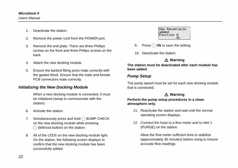
8. All of the LEDS on the new docking module light. On the station, the following screen displays to confirm that the new docking module has been successfully added.
9. Press C Ok to save the setting.
10. Deactivate the station.
a Warning The station must be deactivated after each module has been added.
Pump Setup The pump speed must be set for each new docking module that is connected.
a Warning Perform the pump setup procedures in a clean atmosphere only.
11. Reactivate the station and wait until the normal operating screen displays.
12. Connect the hose to a flow meter and to inlet 1 (PURGE) on the station.
Allow the flow meter sufficient time to stabilize (approximately 30 minutes) before using to ensure accurate flow readings.
22
MicroDock II Adding Another Docking Module
13. From the station, access the user options menu.
14. Press C or C to scroll to the Pump Setup option.
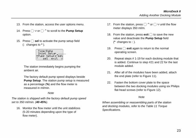
15. Press C sel to activate the pump setup field (: changes to *).
The station immediately begins pumping the ambient air.
The factory default pump speed displays beside Pump Setup. The station pump setup is measured as a percentage (%) and the flow meter is measured in ml/min.
Note
The station is shipped with the factory default pump speed set to 350 ml/min. (40-45%).
16. Monitor the flow meter until the unit stabilizes (5-20 minutes depending upon the type of flow meter).
17. From the station, press C or C until the flow meter displays 350 ml/m.
18. From the station, press exit C to save the new value and deactivate the Pump Setup field (* changes to :).
19. Press C exit again to return to the normal operating screen.
20. Repeat steps # 1-19 for each docking module that is added. Continue to step #21 and 22 for the last module added.
21. After all of the modules have been added, attach the end plate (refer to Figure 11).
22. Fasten the bottom cover plate to the space between the two docking modules using six Philips flat-head screws (refer to Figure 12).
Note
When assembling or reassembling parts of the station and docking modules, refer to the Table 11 Torque Specifications.
23
MicroDock II Users Manual
Mounting the MicroDock II
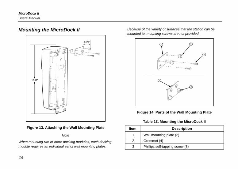
Figure 13. Attaching the Wall Mounting Plate
Note
When mounting two or more docking modules, each docking module requires an individual set of wall mounting plates.
Because of the variety of surfaces that the station can be mounted to, mounting screws are not provided.
Figure 14. Parts of the Wall Mounting Plate
Table 13. Mounting the MicroDock II
Item Description 1 Wall mounting plate (2)
2 Grommet (4)
3 Phillips self-tapping screw (8)
24
MicroDock II Changing Dip Switch Settings
The MicroDock II station can be easily mounted to a secure surface. To mount the station, complete the following:
1. Determine a secure location where the station is to be mounted.
Using the screws that are provided, attach the wall mounting plates to the station/docking modules.
2. When the plates are mounted on the station, measure horizontally on the wall the width of the station; 2.38 in. (60.32 mm).
If two or more docking modules that are attached together are being mounted on the wall, measure a distance of 1.64 in. (41.7 mm) of space between each docking module.
3. Use four screws to attach the station to the secure surface.
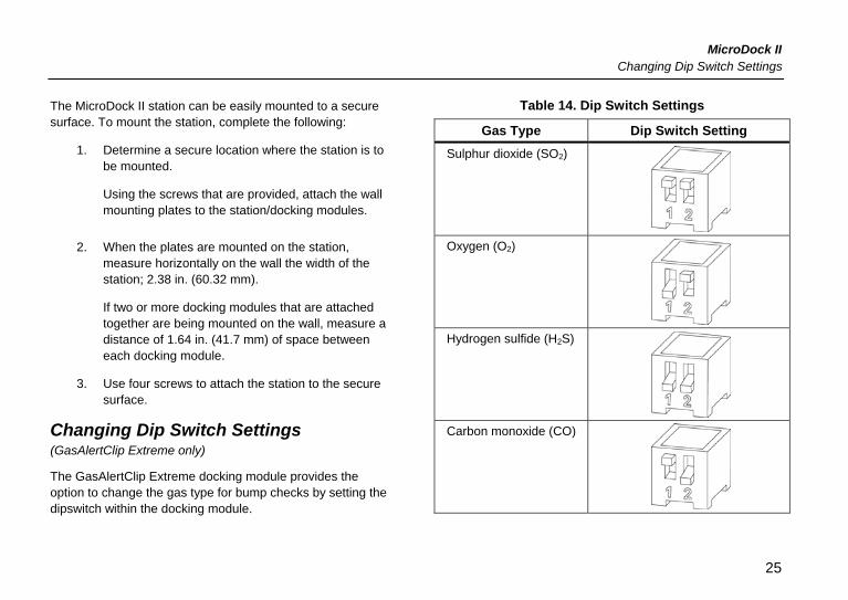
Changing Dip Switch Settings (GasAlertClip Extreme only)
The GasAlertClip Extreme docking module provides the option to change the gas type for bump checks by setting the dipswitch within the docking module.
Table 14. Dip Switch Settings
Gas Type Dip Switch Setting Sulphur dioxide (SO2)
Oxygen (O2)
Hydrogen sulfide (H2S)
Carbon monoxide (CO)
25
MicroDock II Users Manual
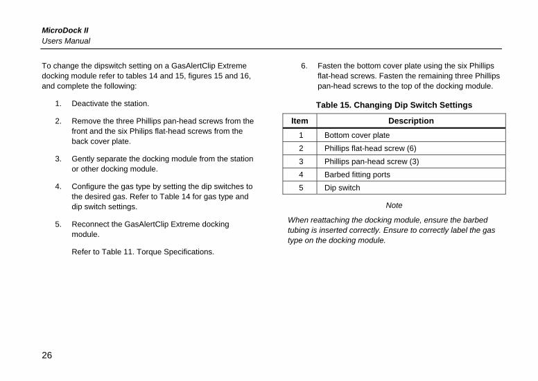
To change the dipswitch setting on a GasAlertClip Extreme docking module refer to tables 14 and 15, figures 15 and 16, and complete the following:
1. Deactivate the station.
2. Remove the three Phillips pan-head screws from the front and the six Philips flat-head screws from the back cover plate.
3. Gently separate the docking module from the station or other docking module.
4. Configure the gas type by setting the dip switches to the desired gas. Refer to Table 14 for gas type and dip switch settings.
5. Reconnect the GasAlertClip Extreme docking module.
Refer to Table 11. Torque Specifications.
6. Fasten the bottom cover plate using the six Phillips flat-head screws. Fasten the remaining three Phillips pan-head screws to the top of the docking module.
Table 15. Changing Dip Switch Settings
Item Description 1 Bottom cover plate
2 Phillips flat-head screw (6)
3 Phillips pan-head screw (3)
4 Barbed fitting ports
5 Dip switch
Note
When reattaching the docking module, ensure the barbed tubing is inserted correctly. Ensure to correctly label the gas type on the docking module.
26
MicroDock II Changing Dip Switch Settings
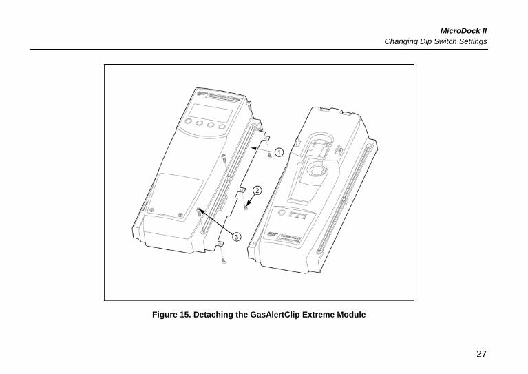
Figure 15. Detaching the GasAlertClip Extreme Module
27
MicroDock II Users Manual
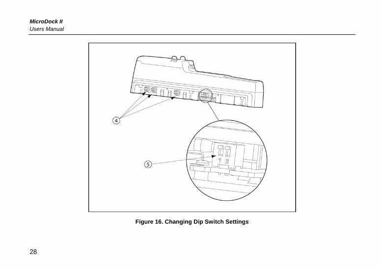
Figure 16. Changing Dip Switch Settings
28
MicroDock II How to Use the Base Station
How to Use the Base Station a Warning
To prevent possible injury and/or property damage, only use the station in an atmosphere that is clear of hazardous gas. Ensure that the station is attached to a venting system or used in a well ventilated area.
The station pushbuttons are not labelled. The station is operated by pressing the C pushbutton that is located directly below the option that displays on the LCD.
Confirming Inlet Setup a Warning
Failed tests can result if the inlets are not setup correctly.
Before activating the station for the first time, ensure that the gas cylinders are connected to the inlets correctly. Refer to Installation. To confirm that the inlets are setup correctly, refer to Inlet Setup in the User Options Menu section.
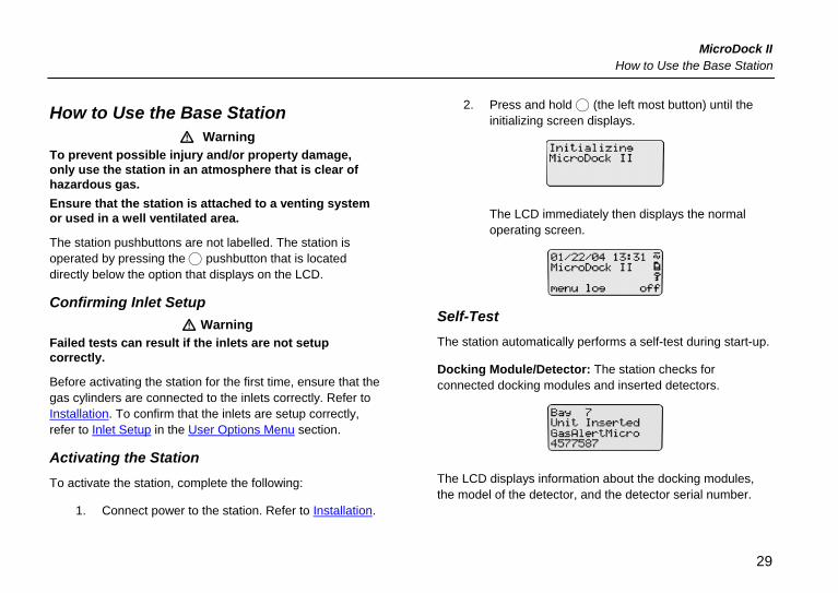
Activating the Station To activate the station, complete the following:
1. Connect power to the station. Refer to Installation.
2. Press and hold C (the left most button) until the initializing screen displays.
The LCD immediately then displays the normal operating screen.
Self-Test The station automatically performs a self-test during start-up.
Docking Module/Detector: The station checks for connected docking modules and inserted detectors.
The LCD displays information about the docking modules, the model of the detector, and the detector serial number.
29
MicroDock II Users Manual
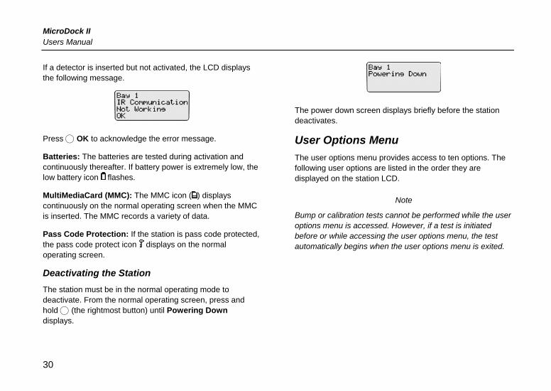
If a detector is inserted but not activated, the LCD displays the following message.
Press C OK to acknowledge the error message.
Batteries: The batteries are tested during activation and continuously thereafter. If battery power is extremely low, the low battery icon flashes.
MultiMediaCard (MMC): The MMC icon ( ) displays continuously on the normal operating screen when the MMC is inserted. The MMC records a variety of data.
Pass Code Protection: If the station is pass code protected, the pass code protect icon displays on the normal operating screen.
Deactivating the Station The station must be in the normal operating mode to deactivate. From the normal operating screen, press and hold C (the rightmost button) until Powering Down displays.
The power down screen displays briefly before the station deactivates.
User Options Menu
The user options menu provides access to ten options. The following user options are listed in the order they are displayed on the station LCD.
Note
Bump or calibration tests cannot be performed while the user options menu is accessed. However, if a test is initiated before or while accessing the user options menu, the test automatically begins when the user options menu is exited.
30
MicroDock II User Options Menu
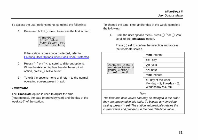
To access the user options menu, complete the following:
1. Press and hold C menu to access the first screen.
If the station is pass code protected, refer to Entering User Options when Pass Code Protected.
2. Press C or C to scroll to different options. When the icon displays beside the required option, press C sel to select.
3. To exit the options menu and return to the normal operating screen, press C exit.
Time/Date The Time/Date option is used to adjust the time (hour/minute), the date (month/day/year) and the day of the week (1-7) of the station.
To change the date, time, and/or day of the week, complete the following:
1. From the user options menu, press C or C to scroll to the Time/Date option.
Press C sel to confirm the selection and access the time/date screen.
mm: month
dd: day
yy: year
hh: hour
mm: minute
d: day of the week Monday = 1, Tuesday = 2, Wednesday = 3, etc.
Note The time and date values can only be changed in the order they are presented in this table. To bypass any time/date setting, press C sel. The station automatically retains the current value and proceeds to the next date/time value.
31
MicroDock II Users Manual
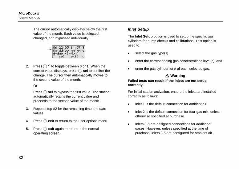
The cursor automatically displays below the first value of the month. Each value is selected, changed, and bypassed individually.
2. Press C to toggle between 0 or 1. When the correct value displays, press C sel to confirm the change. The cursor then automatically moves to the second value of the month.
Or
Press C sel to bypass the first value. The station automatically retains the current value and proceeds to the second value of the month.
3. Repeat step #2 for the remaining time and date values.
4. Press C exit to return to the user options menu.
5. Press C exit again to return to the normal operating screen.
Inlet Setup The Inlet Setup option is used to setup the specific gas cylinders for bump checks and calibrations. This option is used to
• select the gas type(s)
• enter the corresponding gas concentrations level(s), and
• enter the gas cylinder lot # of each selected gas.
a Warning Failed tests can result if the inlets are not setup correctly.
For initial station activation, ensure the inlets are installed correctly as follows:
• Inlet 1 is the default connection for ambient air.
• Inlet 2 is the default connection for four-gas mix, unless otherwise specified at purchase.
• Inlets 3-5 are designed connections for additional gases. However, unless specified at the time of purchase, inlets 3-5 are configured for ambient air.
32
MicroDock II User Options Menu
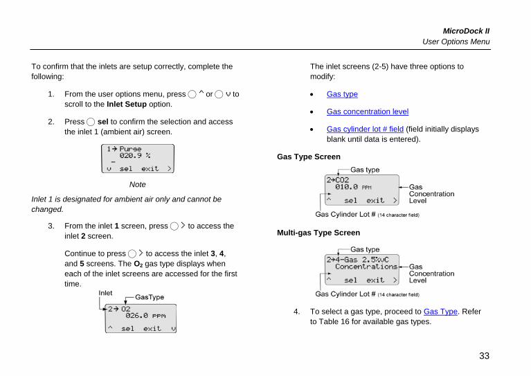
To confirm that the inlets are setup correctly, complete the following:
1. From the user options menu, press C or C to scroll to the Inlet Setup option.
2. Press C sel to confirm the selection and access the inlet 1 (ambient air) screen.
Note
Inlet 1 is designated for ambient air only and cannot be changed.
3. From the inlet 1 screen, press C to access the inlet 2 screen.
Continue to press C to access the inlet 3, 4, and 5 screens. The O2 gas type displays when each of the inlet screens are accessed for the first time.
The inlet screens (2-5) have three options to modify:
• Gas type
• Gas concentration level
• Gas cylinder lot # field (field initially displays blank until data is entered).
Gas Type Screen
Multi-gas Type Screen
4. To select a gas type, proceed to Gas Type. Refer to Table 16 for available gas types.
33
MicroDock II Users Manual
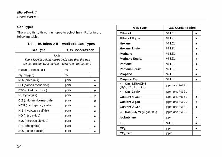
Gas Type: There are thirty-three gas types to select from. Refer to the following table.
Table 16. Inlets 2-5 – Available Gas Types
Gas Type Gas Concentration
Note The * icon in column three indicates that the gas
concentration level can be modified on the station.
Purge (ambient air) % O2 (oxygen) % NH3 (ammonia) ppm * CO (carbon monoxide) ppm * ETO (ethylene oxide) ppm * H2 (hydrogen) ppm * Cl2 (chlorine) bump only ppm * HCN (hydrogen cyanide) ppm * H2S (hydrogen sulfide) ppm * NO (nitric oxide) ppm * NO2 (nitrogen dioxide) ppm * PH3 (phosphine) ppm * SO2 (sulfur dioxide) ppm *
Gas Type Gas Concentration
Ethanol % LEL * Ethanol Equiv. % LEL * Hexane % LEL * Hexane Equiv. % LEL * Methane % LEL * Methane Equiv. % LEL * Pentane % LEL * Pentane Equiv. % LEL * Propane % LEL * Propane Equi % LEL * 4 – Gas 2.5%vCH4 (H2S, CO, LEL, O2)
ppm and %LEL 4 – Gas Equiv. ppm and %LEL Custom 4-Gas ppm and %LEL * Custom 3-gas ppm and %LEL * Custom 2-Gas ppm and %LEL * 3 – Gas SO2 Mi (3-gas mix) ppm and %LEL Isobutylene ppm * LEL %LEL * CO2 ppm * CO2 zero ppm
34
MicroDock II User Options Menu
Note
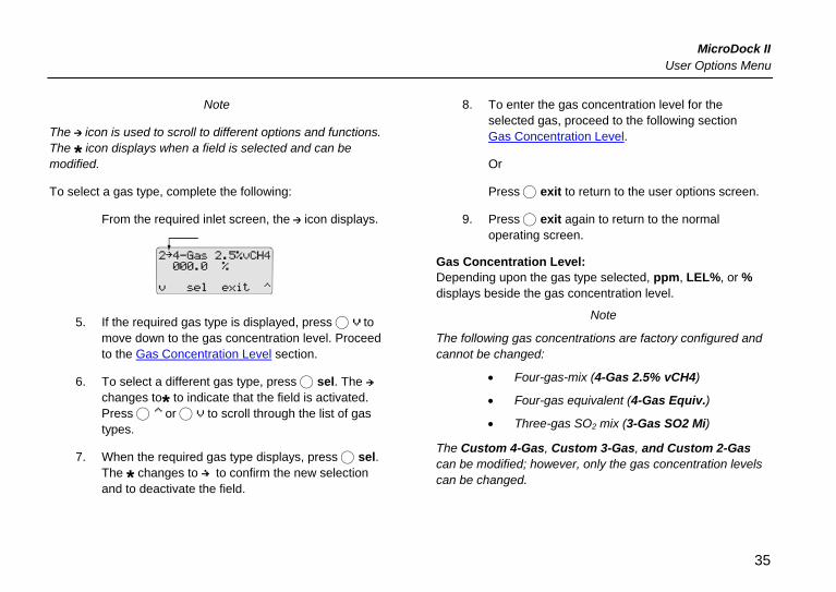
The icon is used to scroll to different options and functions. The * icon displays when a field is selected and can be modified.
To select a gas type, complete the following:
From the required inlet screen, the icon displays.
5. If the required gas type is displayed, press C to move down to the gas concentration level. Proceed to the Gas Concentration Level section.
6. To select a different gas type, press C sel. The changes to* to indicate that the field is activated. Press C or C to scroll through the list of gas types.
7. When the required gas type displays, press C sel. The * changes to to confirm the new selection and to deactivate the field.
8. To enter the gas concentration level for the selected gas, proceed to the following section Gas Concentration Level.
Or
Press C exit to return to the user options screen.
9. Press C exit again to return to the normal operating screen.
Gas Concentration Level: Depending upon the gas type selected, ppm, LEL%, or % displays beside the gas concentration level.
Note
The following gas concentrations are factory configured and cannot be changed:
• Four-gas-mix (4-Gas 2.5% vCH4)
• Four-gas equivalent (4-Gas Equiv.)
• Three-gas SO2 mix (3-Gas SO2 Mi)
The Custom 4-Gas, Custom 3-Gas, and Custom 2-Gas can be modified; however, only the gas concentration levels can be changed.
35
MicroDock II Users Manual
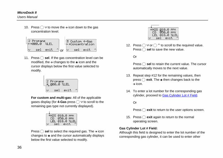
10. Press C to move the icon down to the gas concentration level.
or
11. Press C sel. If the gas concentration level can be modified, the changes to the * icon and the cursor displays below the first value selected to modify.
For custom and multi-gas: All of the applicable gases display (for 4-Gas press C to scroll to the remaining gas type not currently displayed).
Press C sel to select the required gas. The icon changes to * and the cursor automatically displays below the first value selected to modify.
12. Press C or C to scroll to the required value. Press C sel to save the new value.
Or
Press C sel to retain the current value. The cursor automatically moves to the next value.
13. Repeat step #12 for the remaining values, then press C exit. The * then changes back to the
icon.
14. To enter a lot number for the corresponding gas cylinder, proceed to Gas Cylinder Lot # Field.
Or
Press C exit to return to the user options screen.
15. Press C exit again to return to the normal operating screen.
Gas Cylinder Lot # Field: Although this field is designed to enter the lot number of the corresponding gas cylinder, it can be used to enter other
36
MicroDock II User Options Menu
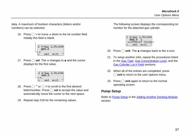
data. A maximum of fourteen characters (letters and/or numbers) can be selected.
16. Press C to move down to the lot number field. Initially this field is blank.
17. Press C sel. The changes to * and the cursor displays for the first value.
18. Press C or C to scroll to the first desired letter/number. Press C sel to accept the value and automatically move the cursor to the next space.
19. Repeat step #18 for the remaining values.
The following screen displays the corresponding lot number for the attached gas cylinder.
20. Press C exit. The * changes back to the icon.
21. To setup another inlet, repeat the procedures listed in the Gas Type, Gas Concentration Level, and the Gas Cylinder Lot # Field sections.
22. When all of the entries are completed, press C exit to return to the user options menu.
23. Press C exit again to return to the normal operating screen.
Pump Setup Refer to Pump Setup in the Adding Another Docking Module section.
37
MicroDock II Users Manual
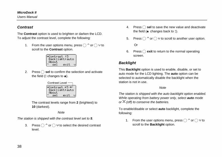
Contrast The Contrast option is used to brighten or darken the LCD. To adjust the contrast level, complete the following:
1. From the user options menu, press C or C to scroll to the Contrast option.
2. Press C sel to confirm the selection and activate the field (: changes to *).
The contrast levels range from 2 (brightest) to 10 (darkest).
Note
The station is shipped with the contrast level set to 5.
3. Press C or C to select the desired contrast level.
4. Press C sel to save the new value and deactivate the field (* changes back to :).
5. Press C or C to scroll to another user option.
Or
6. Press C exit to return to the normal operating screen.
Backlight This Backlight option is used to enable, disable, or set to auto mode for the LCD lighting. The auto option can be selected to automatically disable the backlight when the station is not in use.
Note
The station is shipped with the auto backlight option enabled. While operating from battery power only, select auto mode or (off) to conserve the batteries.
To enable/disable or select auto backlight, complete the following:
1. From the user options menu, press C or C to scroll to the Backlight option.
38
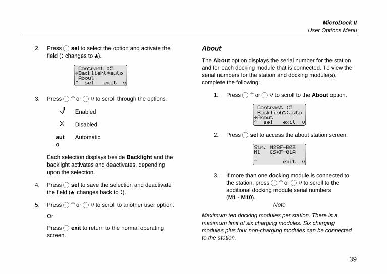
MicroDock II User Options Menu
2. Press C sel to select the option and activate the field (: changes to *).
3. Press C or C to scroll through the options.
Enabled
Disabled
auto
Automatic
Each selection displays beside Backlight and the backlight activates and deactivates, depending upon the selection.
4. Press C sel to save the selection and deactivate the field (* changes back to :).
5. Press C or C to scroll to another user option.
Or
Press C exit to return to the normal operating screen.
About The About option displays the serial number for the station and for each docking module that is connected. To view the serial numbers for the station and docking module(s), complete the following:
1. Press C or C to scroll to the About option.
2. Press C sel to access the about station screen.
3. If more than one docking module is connected to the station, press C or C to scroll to the additional docking module serial numbers (M1 - M10).
Note
Maximum ten docking modules per station. There is a maximum limit of six charging modules. Six charging modules plus four non-charging modules can be connected to the station.
39
MicroDock II Users Manual
Format the MultiMediaCard (MMC) This option is used to format the MultiMediaCard (MMC).
Note
If a previously formatted MMC is used to reformat, all of the data on the card will be erased.
To format an MMC, complete the following:
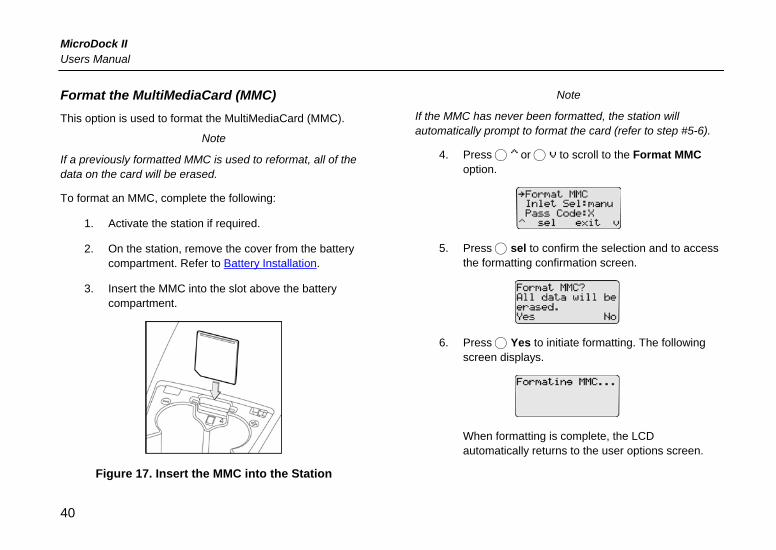
1. Activate the station if required.
2. On the station, remove the cover from the battery compartment. Refer to Battery Installation.
3. Insert the MMC into the slot above the battery compartment.
Figure 17. Insert the MMC into the Station
Note
If the MMC has never been formatted, the station will automatically prompt to format the card (refer to step #5-6).
4. Press C or C to scroll to the Format MMC option.
5. Press C sel to confirm the selection and to access the formatting confirmation screen.
6. Press C Yes to initiate formatting. The following screen displays.
When formatting is complete, the LCD automatically returns to the user options screen.
40
MicroDock II User Options Menu
If No is selected, the LCD automatically returns to the user options screen. If there is a problem with the card, the following screen displays.
Press C OK to acknowledge and insert a new card and repeat the procedures.
7. Press C or C to scroll to another user option.
Or
Press C exit to return to the normal operating screen.
For additional information about the MMC, refer to Base Station MultiMediaCard (MMC).
Inlet Select Note
Applicable only to custom and multi-gas types.
The Inlet Sel option is used to enable either the automatic (auto) or manual (manu) function for selecting an inlet.
If the auto option is enabled, the station automatically selects the correct gas inlet for the bump check or calibration.
If manu is enabled, the applicable test gas must be selected each time a bump/calibration is performed. If the manu option is enabled, refer to Order of Gases Applied for Bump Checks and Calibrations for important information.
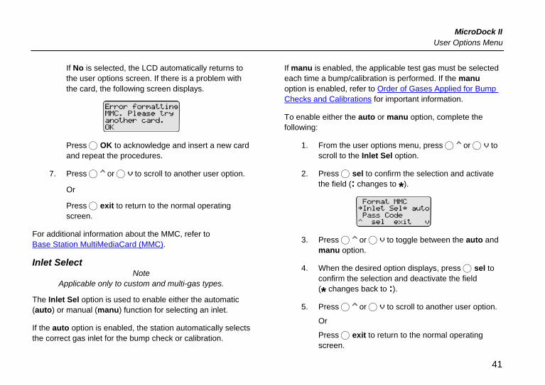
To enable either the auto or manu option, complete the following:
1. From the user options menu, press C or C to scroll to the Inlet Sel option.
2. Press C sel to confirm the selection and activate the field (: changes to *).
3. Press C or C to toggle between the auto and manu option.
4. When the desired option displays, press C sel to confirm the selection and deactivate the field (* changes back to :).
5. Press C or C to scroll to another user option.
Or
Press C exit to return to the normal operating screen.
41
MicroDock II Users Manual
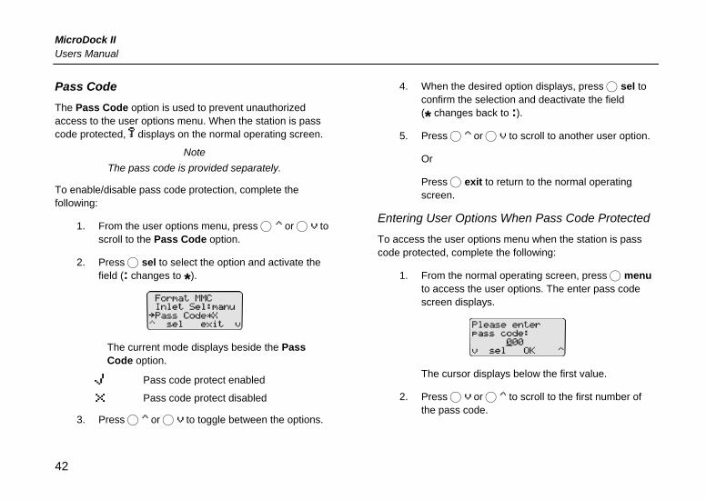
Pass Code The Pass Code option is used to prevent unauthorized access to the user options menu. When the station is pass code protected, displays on the normal operating screen.
Note The pass code is provided separately.
To enable/disable pass code protection, complete the following:
1. From the user options menu, press C or C to scroll to the Pass Code option.
2. Press C sel to select the option and activate the field (: changes to *).
The current mode displays beside the Pass Code option.
Pass code protect enabled
Pass code protect disabled
3. Press C or C to toggle between the options.
4. When the desired option displays, press C sel to confirm the selection and deactivate the field (* changes back to :).
5. Press C or C to scroll to another user option.
Or
Press C exit to return to the normal operating screen.
Entering User Options When Pass Code Protected
To access the user options menu when the station is pass code protected, complete the following:
1. From the normal operating screen, press C menu to access the user options. The enter pass code screen displays.
The cursor displays below the first value.
2. Press C or C to scroll to the first number of the pass code.
42
MicroDock II User Options Menu
When the correct value displays, press C sel to save the first value. The cursor automatically moves to the next value.
3. Repeat step #2 for the remaining values.
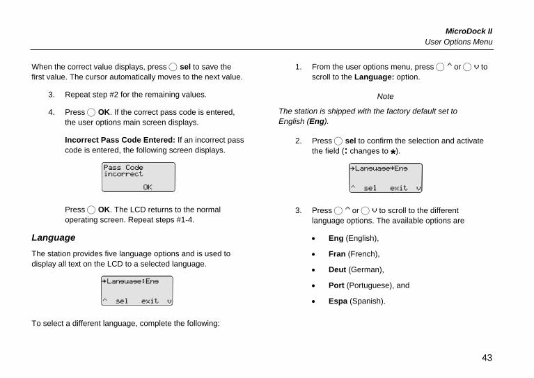
4. Press C OK. If the correct pass code is entered, the user options main screen displays.
Incorrect Pass Code Entered: If an incorrect pass code is entered, the following screen displays.
Press C OK. The LCD returns to the normal operating screen. Repeat steps #1-4.
Language
The station provides five language options and is used to display all text on the LCD to a selected language.
To select a different language, complete the following:
1. From the user options menu, press C or C to scroll to the Language: option.
Note
The station is shipped with the factory default set to English (Eng).
2. Press C sel to confirm the selection and activate the field (: changes to *).
3. Press C or C to scroll to the different language options. The available options are
• Eng (English),
• Fran (French),
• Deut (German),
• Port (Portuguese), and
• Espa (Spanish).
43
MicroDock II Users Manual
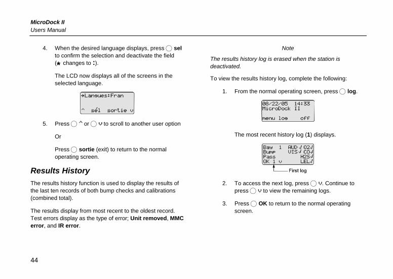
4. When the desired language displays, press C sel to confirm the selection and deactivate the field (* changes to :). The LCD now displays all of the screens in the selected language.
5. Press C or C to scroll to another user option
Or
Press C sortie (exit) to return to the normal operating screen.
Results History The results history function is used to display the results of the last ten records of both bump checks and calibrations (combined total).
The results display from most recent to the oldest record. Test errors display as the type of error; Unit removed, MMC error, and IR error.
Note
The results history log is erased when the station is deactivated.
To view the results history log, complete the following:
1. From the normal operating screen, press C log.
The most recent history log (1) displays.
2. To access the next log, press C . Continue to press C to view the remaining logs.
3. Press C OK to return to the normal operating screen.
44
MicroDock II Reconfiguring the Detector
Reconfiguring the Detector (Not applicable to the GasAlertClip Extreme)
The detector can be reconfigured prior to performing a bump check or calibration to change the alarm setpoints and other settings.
Fleet Manager
• GasAlert Extreme
• GasAlertMicro
• GasAlertMicro 5 and GasAlertMicro 5 PID
• GasAlertMicroClip
Changing Settings 1. Ensure that a correctly formatted MultiMediaCard
(MMC) is inserted in the station. Refer to Inserting/Replacing a MMC.
2. Connect the USB cable to the computer and to the USB port on the station.
3. Activate the detector and wait until it is in normal operating mode. Insert it into the detector bay.
4. Activate the station.
5. From the computer, open Fleet Manager.
6. Located at the bottom of the left menu bar, click Administrator.
7. Enter your password in the password pop-up.
8. From the left menu bar, click the Configure Detectors icon.
9. The configuration pop-up displays. Select either
• Load Existing MicroDock Configuration File (select to use an existing file to configure/reconfigure a detector), or
• Create New MicroDock Configuration File (select to create a new configuration file to configure/reconfigure a detector).
10. Click the tab of the required detector (e.g. GasAlertMicro 5) to access the corresponding configuration screen.
45
MicroDock II Users Manual
11. Each configuration screen provides the following options to select from:
• Do Not Reconfigure
• Reconfigure with user’s consent (Date and Time NOT reconfigured)
• Automatic Reconfigure (Date and Time NOT reconfigured)
• Reconfigure with user’s consent (Date and Time ARE reconfigured) Not applicable to GasAlertMicroClip
• Automatic Reconfigure (Date and Time ARE reconfigured) Not applicable to GasAlertMicroClip
Click the checkbox of the desired option.
12. Click the remaining checkboxes on the screen to make the desired configuration changes.
Note
If the time and date are set to be reconfigured in Fleet Manager, ensure the time and date is set correctly on the station.
13. Determine if the configuration is to be saved to the station or to a folder on the hard drive.
Save to MicroDock II Base Station
• Located at the bottom right of the configuration screen, click the checkbox beside Save file to MMC.
• The station and corresponding docking module(s) serial numbers display below. Click the required station serial number.
• From the top left of the configuration screen, click Save. The configuration file automatically transfers to the station.
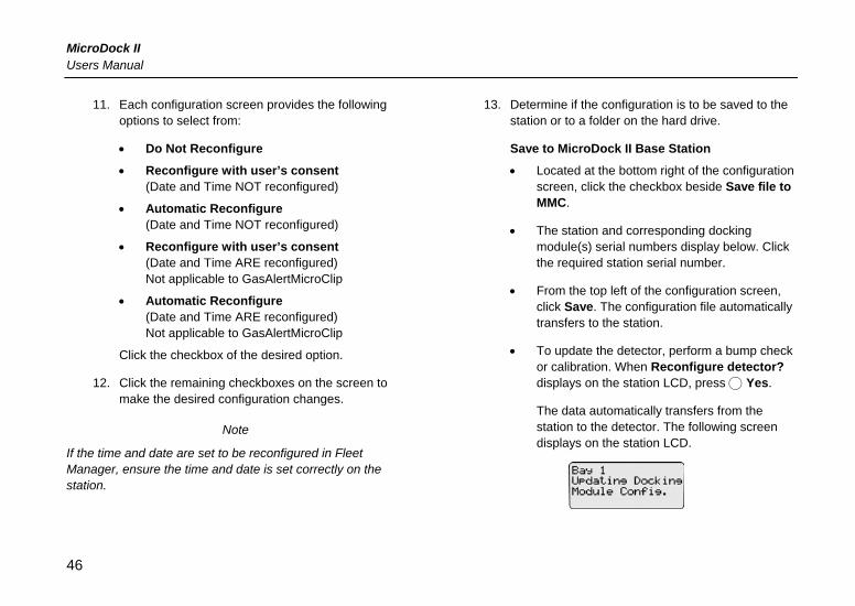
• To update the detector, perform a bump check or calibration. When Reconfigure detector? displays on the station LCD, press C Yes.
The data automatically transfers from the station to the detector. The following screen displays on the station LCD.
46
MicroDock II Reconfiguring the Detector
Save to File to Hard Drive
• Located at the bottom left of the configuration screen, enter the folder name of where the file is to be saved.
Or, press to browse for the required folder.
• From the top left of the configuration screen, press Save. The data automatically saves to the selected file.
Automatic Reconfiguration
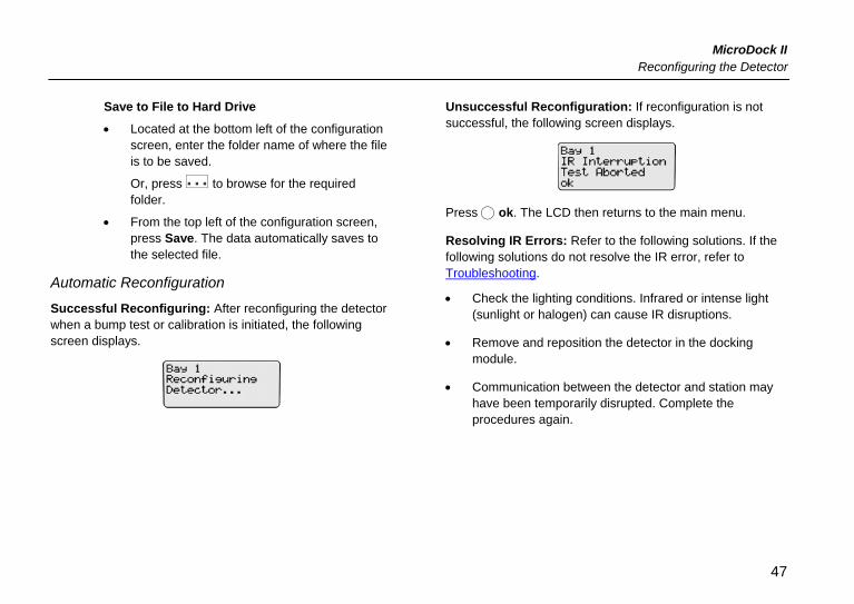
Successful Reconfiguring: After reconfiguring the detector when a bump test or calibration is initiated, the following screen displays.
Unsuccessful Reconfiguration: If reconfiguration is not successful, the following screen displays.
Press C ok. The LCD then returns to the main menu.
Resolving IR Errors: Refer to the following solutions. If the following solutions do not resolve the IR error, refer to Troubleshooting.
• Check the lighting conditions. Infrared or intense light (sunlight or halogen) can cause IR disruptions.
• Remove and reposition the detector in the docking module.
• Communication between the detector and station may have been temporarily disrupted. Complete the procedures again.
47
MicroDock II Users Manual
Reconfigure with User’s Consent (Manual Reconfiguration)
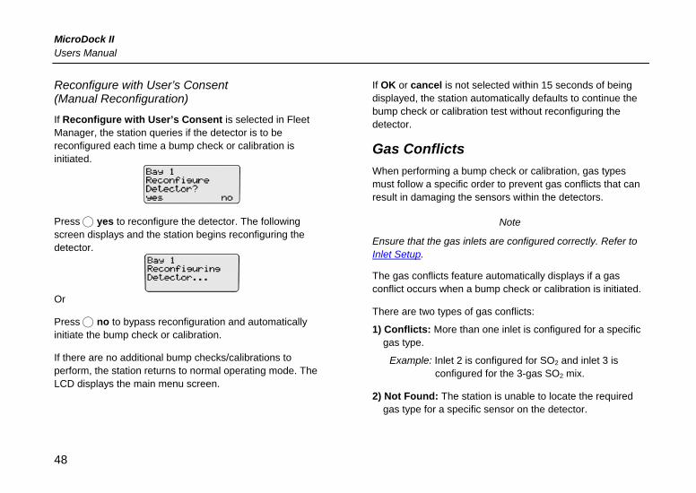
If Reconfigure with User’s Consent is selected in Fleet Manager, the station queries if the detector is to be reconfigured each time a bump check or calibration is initiated.
Press C yes to reconfigure the detector. The following screen displays and the station begins reconfiguring the detector.
Or
Press C no to bypass reconfiguration and automatically initiate the bump check or calibration.
If there are no additional bump checks/calibrations to perform, the station returns to normal operating mode. The LCD displays the main menu screen.
If OK or cancel is not selected within 15 seconds of being displayed, the station automatically defaults to continue the bump check or calibration test without reconfiguring the detector.
Gas Conflicts When performing a bump check or calibration, gas types must follow a specific order to prevent gas conflicts that can result in damaging the sensors within the detectors.
Note
Ensure that the gas inlets are configured correctly. Refer to Inlet Setup.
The gas conflicts feature automatically displays if a gas conflict occurs when a bump check or calibration is initiated.
There are two types of gas conflicts:
1) Conflicts: More than one inlet is configured for a specific gas type.
Example: Inlet 2 is configured for SO2 and inlet 3 is configured for the 3-gas SO2 mix.
2) Not Found: The station is unable to locate the required gas type for a specific sensor on the detector.
48
MicroDock II Gas Conflicts
The station displays additional information regarding the
• number of gas conflicts,
• number of gases not found,
• docking module (e.g., Bay 1),
• detector gas type(s),
• inlet, and
• inlet gas type(s).
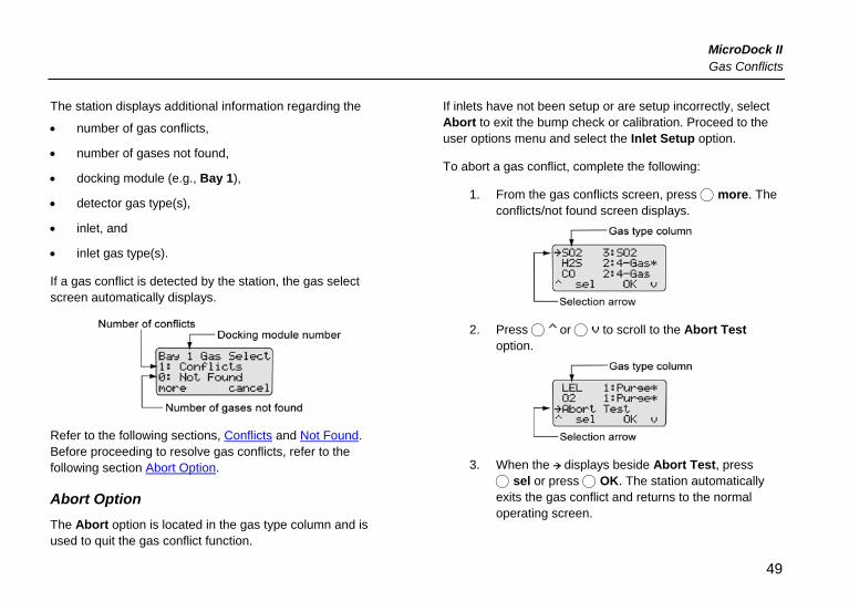
If a gas conflict is detected by the station, the gas select screen automatically displays.
Refer to the following sections, Conflicts and Not Found. Before proceeding to resolve gas conflicts, refer to the following section Abort Option.
Abort Option The Abort option is located in the gas type column and is used to quit the gas conflict function.
If inlets have not been setup or are setup incorrectly, select Abort to exit the bump check or calibration. Proceed to the user options menu and select the Inlet Setup option.
To abort a gas conflict, complete the following:
1. From the gas conflicts screen, press C more. The conflicts/not found screen displays.
2. Press C or C to scroll to the Abort Test option.
3. When the displays beside Abort Test, press C sel or press C OK. The station automatically exits the gas conflict and returns to the normal operating screen.
49
MicroDock II Users Manual
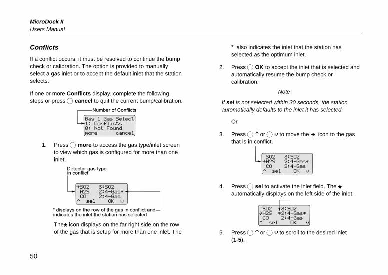
Conflicts If a conflict occurs, it must be resolved to continue the bump check or calibration. The option is provided to manually select a gas inlet or to accept the default inlet that the station selects.
If one or more Conflicts display, complete the following steps or press C cancel to quit the current bump/calibration.
1. Press C more to access the gas type/inlet screen
to view which gas is configured for more than one inlet.
The* icon displays on the far right side on the row of the gas that is setup for more than one inlet. The
* also indicates the inlet that the station has selected as the optimum inlet.
2. Press C OK to accept the inlet that is selected and automatically resume the bump check or calibration.
Note
If sel is not selected within 30 seconds, the station automatically defaults to the inlet it has selected.
Or
3. Press C or C to move the icon to the gas that is in conflict.
4. Press C sel to activate the inlet field. The *
automatically displays on the left side of the inlet.
5. Press C or C to scroll to the desired inlet
(1-5).
50
MicroDock II Gas Conflicts
6. When the required inlet value displays, press C sel to confirm the selection and deactivate the field. The * no longer displays to the right of the inlet indicating the conflict has been resolved.
Unsuccessful Conflict Resolution: If the conflict is not resolved by selecting a different inlet, refer to the following:
• Ensure that the selected inlet is correct.
• Ensure the gas cylinder that is attached to the selected inlet is correct.
• Press C OK to accept the station’s default selection.
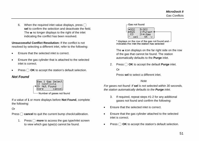
Not Found
If a value of 1 or more displays before Not Found, complete the following:
Or
Press C cancel to quit the current bump check/calibration.
1. Press C more to access the gas type/inlet screen to view which gas type(s) cannot be found.
The * icon displays on the far right side on the row of the gas that cannot be found. The station automatically defaults to the Purge inlet.
2. Press C OK to accept the default Purge inlet.
Or
Press sel to select a different inlet.
Note For gases not found: If sel is not selected within 30 seconds, the station automatically defaults to the Purge inlet.
3. If required, repeat steps #1-2 for any additional gases not found and confirm the following:
• Ensure that the selected inlet is correct.
• Ensure that the gas cylinder attached to the selected inlet is correct.
• Press C OK to accept the station’s default selection.
51
MicroDock II Users Manual
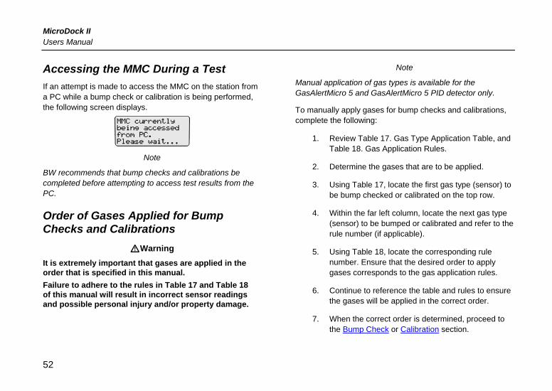
Accessing the MMC During a Test If an attempt is made to access the MMC on the station from a PC while a bump check or calibration is being performed, the following screen displays.
Note
BW recommends that bump checks and calibrations be completed before attempting to access test results from the PC.
Order of Gases Applied for Bump Checks and Calibrations
aWarning It is extremely important that gases are applied in the order that is specified in this manual. Failure to adhere to the rules in Table 17 and Table 18 of this manual will result in incorrect sensor readings and possible personal injury and/or property damage.
Note
Manual application of gas types is available for the GasAlertMicro 5 and GasAlertMicro 5 PID detector only.
To manually apply gases for bump checks and calibrations, complete the following:
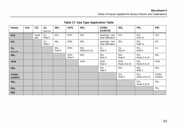
1. Review Table 17. Gas Type Application Table, and Table 18. Gas Application Rules.
2. Determine the gases that are to be applied.
3. Using Table 17, locate the first gas type (sensor) to be bump checked or calibrated on the top row.
4. Within the far left column, locate the next gas type (sensor) to be bumped or calibrated and refer to the rule number (if applicable).
5. Using Table 18, locate the corresponding rule number. Ensure that the desired order to apply gases corresponds to the gas application rules.
6. Continue to reference the table and rules to ensure the gases will be applied in the correct order.
7. When the correct order is determined, proceed to the Bump Check or Calibration section.
52
MicroDock II Order of Gases Applied for Bump Checks and Calibrations
Table 17. Gas Type Application Table
Gases H2S CO CI2 Bump only
NH3 HCN NO2 COSH (H2S/CO)
SO2 PH3 PID
H2S Quad gas
CI2 Rule 4
NH3 HCN NO2 quad gas - one step calibration
SO2 PH3 Rule 11
H2S
CO CI2 Rule 5
NH3 HCN NO2 quad gas - one step calibration
SO2 PH3 Rule 11
CO
CI2 Bump only
NH3 Rule 9
HCN NO2 Rules 8 & 10
CI2 Rule 6
CI2 Rule 9
PH3 Rule 9
CI2
NH3 HCN Rule 9
NO2 NH3 Rule 6
NH3 Rule 9
PH3 Rules 9 & 10
NH3
HCN HCN HCN Rule 6
HCN Rules 8 & 10
PH3 Rules 8 & 10
HCN
NO2 NO2 Rule 6
NO2 NO2 Rule 1
NO2
COSH H2S/CO
SO2 Rule 6
PH3 Rules 10 & 11
COSH H2S/CO
SO2 PH3 Rules 9 & 10
SO2
PH3 PH3
PID
53
MicroDock II Users Manual
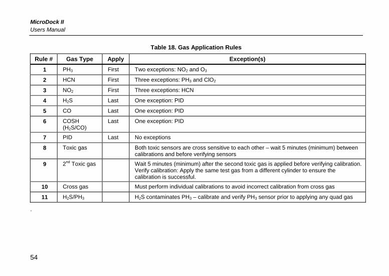
Table 18. Gas Application Rules
Rule # Gas Type Apply Exception(s)
1 PH3 First Two exceptions: NO2 and O3
2 HCN First Three exceptions: PH3 and ClO2
3 NO2 First Three exceptions: HCN
4 H2S Last One exception: PID
5 CO Last One exception: PID
6 COSH (H2S/CO)
Last One exception: PID
7 PID Last No exceptions
8 Toxic gas Both toxic sensors are cross sensitive to each other – wait 5 minutes (minimum) between calibrations and before verifying sensors
9 2nd Toxic gas Wait 5 minutes (minimum) after the second toxic gas is applied before verifying calibration. Verify calibration: Apply the same test gas from a different cylinder to ensure the calibration is successful.
10 Cross gas Must perform individual calibrations to avoid incorrect calibration from cross gas
11 H2S/PH3 H2S contaminates PH3 – calibrate and verify PH3 sensor prior to applying any quad gas
.
54
MicroDock II Bump Check
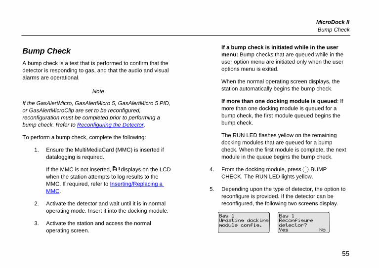
Bump Check A bump check is a test that is performed to confirm that the detector is responding to gas, and that the audio and visual alarms are operational.
Note
If the GasAlertMicro, GasAlertMicro 5, GasAlertMicro 5 PID, or GasAlertMicroClip are set to be reconfigured, reconfiguration must be completed prior to performing a bump check. Refer to Reconfiguring the Detector.
To perform a bump check, complete the following:
1. Ensure the MultiMediaCard (MMC) is inserted if datalogging is required.
If the MMC is not inserted, displays on the LCD when the station attempts to log results to the MMC. If required, refer to Inserting/Replacing a MMC.
2. Activate the detector and wait until it is in normal operating mode. Insert it into the docking module.
3. Activate the station and access the normal operating screen.
If a bump check is initiated while in the user menu: Bump checks that are queued while in the user option menu are initiated only when the user options menu is exited.
When the normal operating screen displays, the station automatically begins the bump check.
If more than one docking module is queued: If more than one docking module is queued for a bump check, the first module queued begins the bump check.
The RUN LED flashes yellow on the remaining docking modules that are queued for a bump check. When the first module is complete, the next module in the queue begins the bump check.
4. From the docking module, press C BUMP CHECK. The RUN LED lights yellow.
5. Depending upon the type of detector, the option to reconfigure is provided. If the detector can be reconfigured, the following two screens display.
55
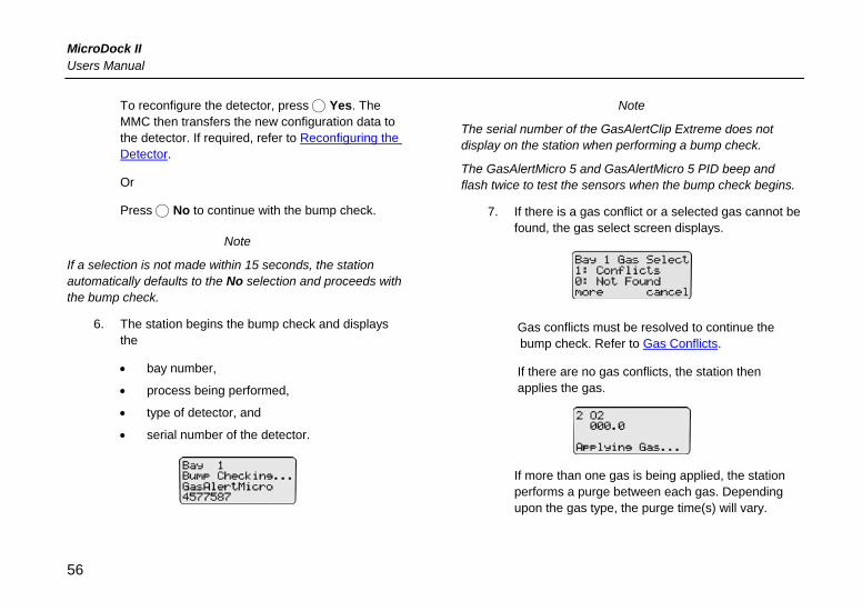
MicroDock II Users Manual
To reconfigure the detector, press C Yes. The MMC then transfers the new configuration data to the detector. If required, refer to Reconfiguring the Detector.
Or
Press C No to continue with the bump check.
Note
If a selection is not made within 15 seconds, the station automatically defaults to the No selection and proceeds with the bump check.
6. The station begins the bump check and displays the
• bay number,
• process being performed,
• type of detector, and
• serial number of the detector.
Note
The serial number of the GasAlertClip Extreme does not display on the station when performing a bump check.
The GasAlertMicro 5 and GasAlertMicro 5 PID beep and flash twice to test the sensors when the bump check begins.
7. If there is a gas conflict or a selected gas cannot be found, the gas select screen displays.
Gas conflicts must be resolved to continue the bump check. Refer to Gas Conflicts.
If there are no gas conflicts, the station then applies the gas.
If more than one gas is being applied, the station performs a purge between each gas. Depending upon the gas type, the purge time(s) will vary.
56
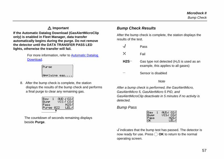
MicroDock II Bump Check
a Important If the Automatic Datalog Download (GasAlertMicroClip only) is enabled in Fleet Manager, data transfer automatically begins during the purge. Do not remove the detector until the DATA TRANSFER PASS LED lights, otherwise the transfer will fail.
For more information, refer to Automatic Datalog Download.
8. After the bump check is complete, the station displays the results of the bump check and performs a final purge to clear any remaining gas.
The countdown of seconds remaining displays beside Purge.
Bump Check Results After the bump check is complete, the station displays the results of the test.
Pass
Fail
H2S_ Gas type not detected (H2S is used as an example, this applies to all gases)
_ Sensor is disabled
Note
After a bump check is performed, the GasAlertMicro, GasAlertMicro 5, GasAlertMicro 5 PID, and GasAlertMicroClip deactivate in 5 minutes if no activity is detected.
Bump Pass
indicates that the bump test has passed. The detector is now ready for use. Press C OK to return to the normal operating screen.
57
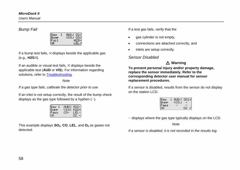
MicroDock II Users Manual
Bump Fail
If a bump test fails, displays beside the applicable gas (e.g., H2S ).
If an audible or visual test fails, displays beside the applicable test (AUD or VIS). For information regarding solutions, refer to Troubleshooting.
Note
If a gas type fails, calibrate the detector prior to use.
If an inlet is not setup correctly, the result of the bump check displays as the gas type followed by a hyphen (_).
This example displays SO2, CO, LEL, and O2 as gases not detected.
If a test gas fails, verify that the
• gas cylinder is not empty,
• connections are attached correctly, and
• inlets are setup correctly.
Sensor Disabled a Warning
To prevent personal injury and/or property damage, replace the sensor immediately. Refer to the corresponding detector user manual for sensor replacement procedures.
If a sensor is disabled, results from the sensor do not display on the station LCD.
_ displays where the gas type typically displays on the LCD.
Note
If a sensor is disabled, it is not recorded in the results log.
58
MicroDock II Calibration
Calibration Guidelines
a Caution If adjustments are made to the real-time clock, the calibration due date will be invalid for the - GasAlert Extreme, - GasAlertMicro, - GasAlertMicro 5, - GasAlertMicro 5 PID, and - GasAlertMicroClip detectors.
Recalibrate the detector immediately.
When calibrating the detector, adhere to the following guidelines:
• Recommended gas mixture: O2: clean air, 20.9% vol. CO: (low H2 sensitivity): 50 to 500 ppm balance N2 CO: 50 to 500 ppm balance N2 H2S (high range): 10 to 100 ppm balance N2 H2S (low methanol): 10 to 100 ppm balance N2 H2S: 10 to 100 ppm balance N2 PH3: 1 to 5 ppm balance N2 SO2: 10 to 50 ppm balance N2 NH3: 20 to 100 ppm balance N2 NH3: (high range) 20 to 100 ppm balance N2 NO2: 5 to 50 ppm balance N2
HCN: 5 to 20 ppm balance N2 ETO: 5 to 50 ppm balance N2 NO: 10 to 250 ppm balance N2 Cl2: 3 to 25 ppm (for bump checks only) VOC: 100 ppm isobutylene LEL:10 to 100% LEL or 0.5 to 5% by vol. methane balance air
• Calibrate only in a clean atmosphere that is free of background gas. Do not operate the station in a hazardous area. Failure to adhere to this guideline can result in possible personal injury and/or property damage.
• BW recommends using premium grade calibration gases and cylinders that are certified to National Standards. The calibration gases must meet the accuracy of the detector.
• Do not use a gas cylinder beyond its expiration date.
• All calibration cylinders must be used with a demand flow regulator and must meet the following maximum inlet pressure specifications:
i. Disposable cylinders 0-1000 psig/70 bar ii. Refillable cylinders 0-3000 psig/207 bar
• Refer to the detector manual for recommended calibration frequencies.
59
MicroDock II Users Manual
• For ETO detectors (before each work shift) allow the instrument to fully stabilize in the temperature that it is to be operated in, and then zero the detector.
• It is necessary to periodically re-zero the ETO detector.
• Calibrate the detector if the ambient gas display varies during start-up.
• Calibrate a new sensor before use. Allow the sensor to stabilize before starting calibration: Used sensor: 60 seconds New sensor: 5 minutes.
• Calibrate the detector at least once every 180 days, depending upon use and sensor exposure to poisons and contaminants. For HCN detectors, calibrate at least once every 90 days.
• Calibrate the sensor before changing the alarm setpoints.
• When calibrating multiple times, wait 10 minutes between calibrations to allow the sensor to stabilize.
• If a certified calibration is required, contact BW Technologies.
Calibration Procedure (All models excluding the GasAlertClip Extreme)
Calibrations are performed to adjust the sensitivity levels of the sensor(s) to ensure accurate responses to gas(es).
The station automatically accepts an unusually large span adjustment notification for the GasAlertMicro 5 and the GasAlertMicro 5 PID. Refer to the GasAlertMicro 5 and GasAlertMicro 5 PID User Manual.
To perform a calibration, complete the following:
1. Ensure the MultiMediaCard (MMC) is inserted if datalogging is required.
If the MMC is not inserted, displays on the LCD when the station attempts to log the results of the calibration. If required, refer to Inserting/Replacing a MMC.
2. Activate the detector and wait until it is in normal operating mode. Insert it into the docking module.
3. Activate the station and access the normal operating screen.
4. Press C CALIBRATION on the corresponding docking module.
60
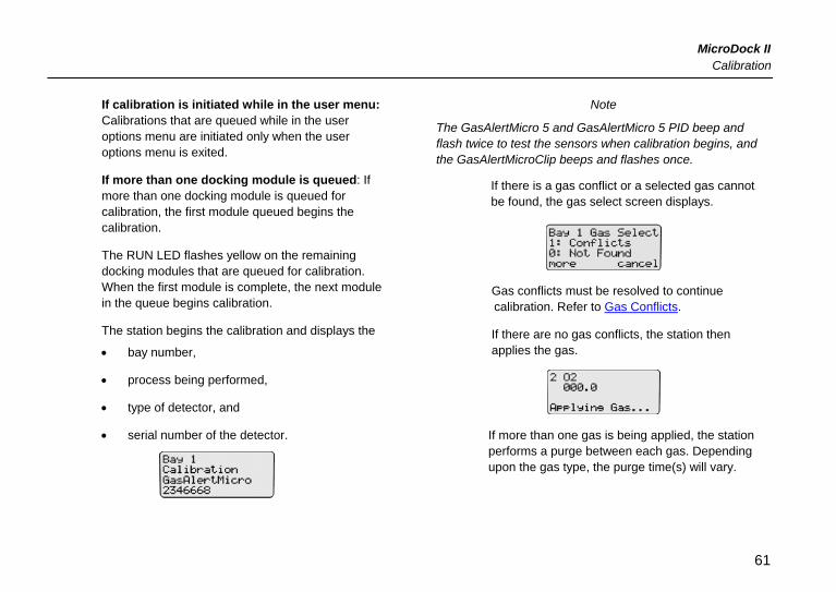
MicroDock II Calibration
If calibration is initiated while in the user menu: Calibrations that are queued while in the user options menu are initiated only when the user options menu is exited.
If more than one docking module is queued: If more than one docking module is queued for calibration, the first module queued begins the calibration.
The RUN LED flashes yellow on the remaining docking modules that are queued for calibration. When the first module is complete, the next module in the queue begins calibration.
The station begins the calibration and displays the
• bay number,
• process being performed,
• type of detector, and
• serial number of the detector.
Note
The GasAlertMicro 5 and GasAlertMicro 5 PID beep and flash twice to test the sensors when calibration begins, and the GasAlertMicroClip beeps and flashes once.
If there is a gas conflict or a selected gas cannot be found, the gas select screen displays.
Gas conflicts must be resolved to continue calibration. Refer to Gas Conflicts.
If there are no gas conflicts, the station then applies the gas.
If more than one gas is being applied, the station performs a purge between each gas. Depending upon the gas type, the purge time(s) will vary.
61
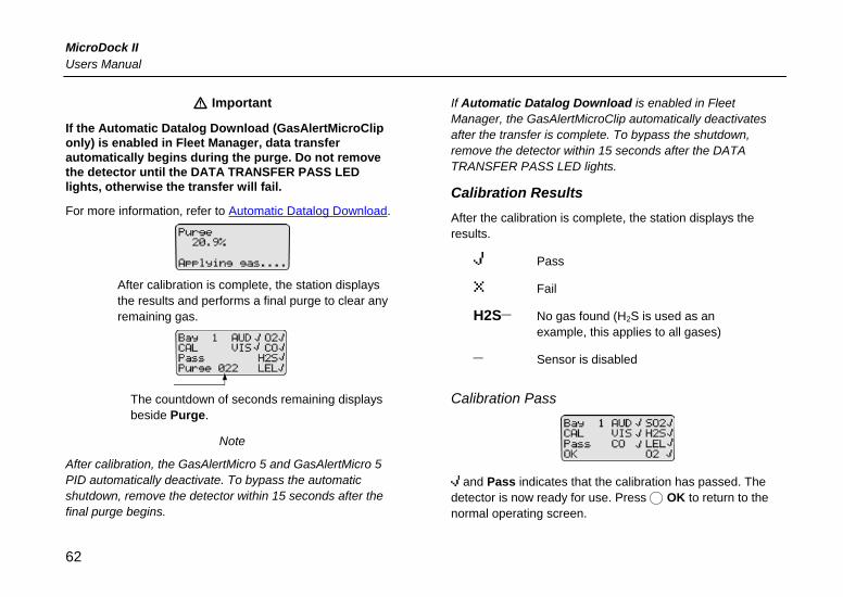
MicroDock II Users Manual
a Important
If the Automatic Datalog Download (GasAlertMicroClip only) is enabled in Fleet Manager, data transfer automatically begins during the purge. Do not remove the detector until the DATA TRANSFER PASS LED lights, otherwise the transfer will fail.
For more information, refer to Automatic Datalog Download.
After calibration is complete, the station displays the results and performs a final purge to clear any remaining gas.
The countdown of seconds remaining displays beside Purge.
Note
After calibration, the GasAlertMicro 5 and GasAlertMicro 5 PID automatically deactivate. To bypass the automatic shutdown, remove the detector within 15 seconds after the final purge begins.
If Automatic Datalog Download is enabled in Fleet Manager, the GasAlertMicroClip automatically deactivates after the transfer is complete. To bypass the shutdown, remove the detector within 15 seconds after the DATA TRANSFER PASS LED lights.
Calibration Results After the calibration is complete, the station displays the results.
Pass
Fail
H2S_ No gas found (H2S is used as an example, this applies to all gases)
_ Sensor is disabled
Calibration Pass
and Pass indicates that the calibration has passed. The detector is now ready for use. Press C OK to return to the normal operating screen.
62
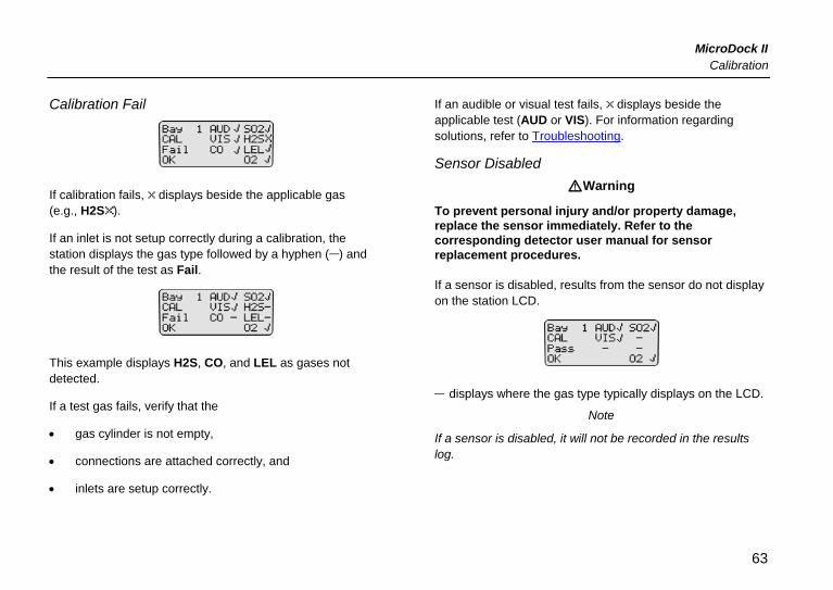
MicroDock II Calibration
Calibration Fail
If calibration fails, displays beside the applicable gas (e.g., H2S ).
If an inlet is not setup correctly during a calibration, the station displays the gas type followed by a hyphen (_) and the result of the test as Fail.
This example displays H2S, CO, and LEL as gases not detected.
If a test gas fails, verify that the
• gas cylinder is not empty,
• connections are attached correctly, and
• inlets are setup correctly.
If an audible or visual test fails, displays beside the applicable test (AUD or VIS). For information regarding solutions, refer to Troubleshooting.
Sensor Disabled aWarning
To prevent personal injury and/or property damage, replace the sensor immediately. Refer to the corresponding detector user manual for sensor replacement procedures.
If a sensor is disabled, results from the sensor do not display on the station LCD.
_ displays where the gas type typically displays on the LCD.
Note
If a sensor is disabled, it will not be recorded in the results log.
63
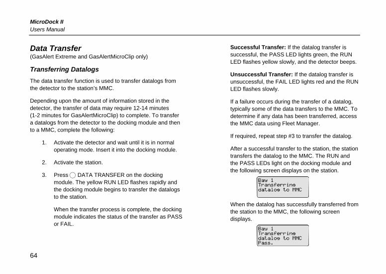
MicroDock II Users Manual
Data Transfer (GasAlert Extreme and GasAlertMicroClip only)
Transferring Datalogs The data transfer function is used to transfer datalogs from the detector to the station’s MMC.
Depending upon the amount of information stored in the detector, the transfer of data may require 12-14 minutes (1-2 minutes for GasAlertMicroClip) to complete. To transfer a datalogs from the detector to the docking module and then to a MMC, complete the following:
1. Activate the detector and wait until it is in normal operating mode. Insert it into the docking module.
2. Activate the station.
3. Press C DATA TRANSFER on the docking module. The yellow RUN LED flashes rapidly and the docking module begins to transfer the datalogs to the station.
When the transfer process is complete, the docking module indicates the status of the transfer as PASS or FAIL.
Successful Transfer: If the datalog transfer is successful, the PASS LED lights green, the RUN LED flashes yellow slowly, and the detector beeps.
Unsuccessful Transfer: If the datalog transfer is unsuccessful, the FAIL LED lights red and the RUN LED flashes slowly.
If a failure occurs during the transfer of a datalog, typically some of the data transfers to the MMC. To determine if any data has been transferred, access the MMC data using Fleet Manager.
If required, repeat step #3 to transfer the datalog.
After a successful transfer to the station, the station transfers the datalog to the MMC. The RUN and the PASS LEDs light on the docking module and the following screen displays on the station.
When the datalog has successfully transferred from the station to the MMC, the following screen displays.
64
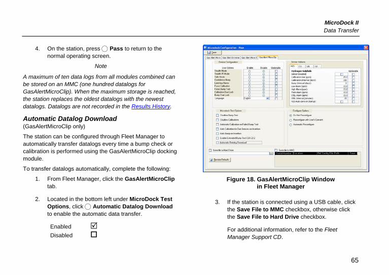
MicroDock II Data Transfer
4. On the station, press C Pass to return to the normal operating screen.
Note
A maximum of ten data logs from all modules combined can be stored on an MMC (one hundred datalogs for GasAlertMicroClip). When the maximum storage is reached, the station replaces the oldest datalogs with the newest datalogs. Datalogs are not recorded in the Results History.
Automatic Datalog Download (GasAlertMicroClip only)
The station can be configured through Fleet Manager to automatically transfer datalogs every time a bump check or calibration is performed using the GasAlertMicroClip docking module.
To transfer datalogs automatically, complete the following:
1. From Fleet Manager, click the GasAlertMicroClip tab.
2. Located in the bottom left under MicroDock Test Options, click C Automatic Datalog Download to enable the automatic data transfer.
Enabled Disabled
Figure 18. GasAlertMicroClip Window in Fleet Manager
3. If the station is connected using a USB cable, click the Save File to MMC checkbox, otherwise click the Save File to Hard Drive checkbox.
For additional information, refer to the Fleet Manager Support CD.
65
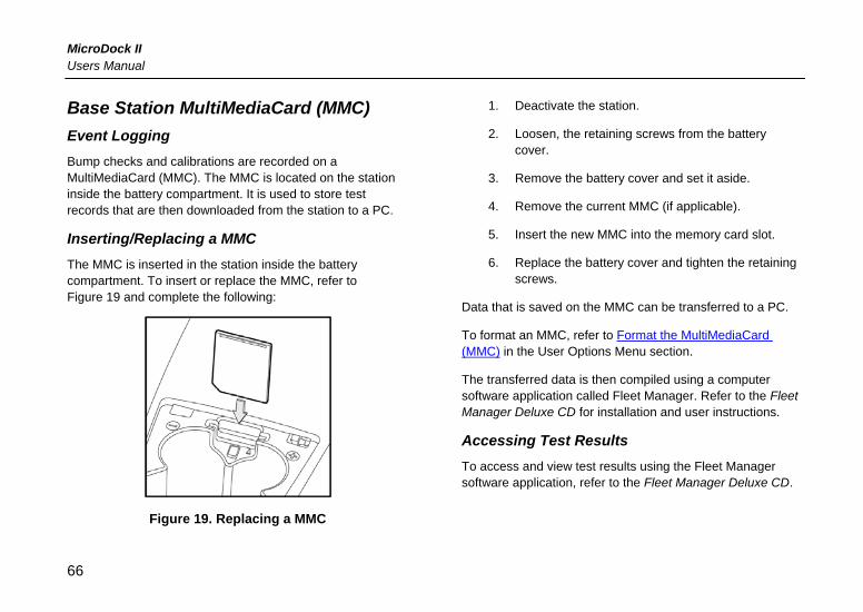
MicroDock II Users Manual
Base Station MultiMediaCard (MMC) Event Logging Bump checks and calibrations are recorded on a MultiMediaCard (MMC). The MMC is located on the station inside the battery compartment. It is used to store test records that are then downloaded from the station to a PC.
Inserting/Replacing a MMC The MMC is inserted in the station inside the battery compartment. To insert or replace the MMC, refer to Figure 19 and complete the following:
Figure 19. Replacing a MMC
1. Deactivate the station.
2. Loosen, the retaining screws from the battery cover.
3. Remove the battery cover and set it aside.
4. Remove the current MMC (if applicable).
5. Insert the new MMC into the memory card slot.
6. Replace the battery cover and tighten the retaining screws.
Data that is saved on the MMC can be transferred to a PC.
To format an MMC, refer to Format the MultiMediaCard (MMC) in the User Options Menu section.
The transferred data is then compiled using a computer software application called Fleet Manager. Refer to the Fleet Manager Deluxe CD for installation and user instructions.
Accessing Test Results To access and view test results using the Fleet Manager software application, refer to the Fleet Manager Deluxe CD.
66
MicroDock II Base Station MultiMediaCard (MMC)
PC Requirements • Microsoft® Windows 98 or later
• 100 MB of available hard-disk space
• 1024 x 768 or higher resolution display
• USB port
• CD-ROM or DVD-ROM drive
Accessing Test Results Using Windows 98, SE, or 2000 To access test results using Windows ’98, SE, or 2000 (without Fleet Manager), complete the following:
1. Connect the USB cable to the PC and to the USB port on the station.
2. Activate the station.
3. From the computer, access Windows Explorer.
4. Locate the Removable Drive and open.
5. Double-click LOGFILE0.CSV to view the test results.
Accessing Test Results Using Windows XP To access the test results using Windows XP (without Fleet Manager), complete the following:
1. Connect the USB cable to the PC and to the USB port on the station.
2. Activate the station.
3. From the computer, access Windows Explorer.
4. The Removable Drive automatically opens. Double-click the required file.
Note
BW recommends that bump checks and calibrations be completed before attempting to access results on the PC.
67
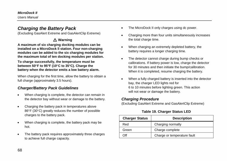
MicroDock II Users Manual
Charging the Battery Pack (Excluding GasAlert Extreme and GasAlertClip Extreme)
a Warning A maximum of six charging docking modules can be installed on a MicroDock ll station. Four non-charging modules can be added to the six charging modules for the maximum total of ten docking modules per station. To charge successfully, the temperature must be between 50°F to 95°F (10°C to 35°C). Charge the battery when the detector emits a low battery alarm.
When charging for the first time, allow the battery to obtain a full charge (approximately 3.5 hours).
Charger/Battery Pack Guidelines • When charging is complete, the detector can remain in
the detector bay without wear or damage to the battery.
• Charging the battery pack in temperatures above 86°F (30°C) greatly reduces the number of possible charges to the battery pack.
• When charging is complete, the battery pack may be hot.
• The battery pack requires approximately three charges to achieve full charge capacity.
• The MicroDock II only charges using dc power.
• Charging more than four units simultaneously increases the total charge time.
• When charging an extremely depleted battery, the battery requires a longer charging time.
• The detector cannot charge during bump checks or calibrations. If battery power is low, charge the detector for 30 minutes and then initiate the bump/calibration. When it is completed, resume charging the battery.
• When a fully charged battery is inserted into the detector bay, the charger LED lights red for 6 to 10 minutes before lighting green. This action will not wear or damage the battery.
Charging Procedure (Excluding GasAlert Extreme and GasAlertClip Extreme)
Table 19. Charger Status LED
Charger Status Description Red Charging normally
Green Charge complete
Off Charge or temperature fault
68
MicroDock II Maintenance
To charge a detector in a charging docking module, complete the following:
1. Connect the ac adapter of the charger to the CHARGE port on the station and then plug the cord into the ac outlet. The charging LED briefly lights red then green during the self-test. The light then powers off.
2. Deactivate the detector and insert into the charging cradle (bottom first). The charging LED then lights red.
Ensure the detector is inserted correctly onto the contact pins.
3. Allow the battery to obtain a full charge. A full charge requires 2-4 hours, depending upon how many docking modules are connected to the station.
The charging LED turns green when charging is complete.
The charging LED powers off when the detector is removed from the charger.
Maintenance a Warning
No user-serviceable parts inside.
To maintain the station in good operating condition, perform the following basic maintenance as required.
• To ensure quality product operation, maintain a log of all maintenance that is performed.
• Clean the exterior with a soft, damp cloth. Do not use solvents, soaps, or polishes.
• Confirm that the inlet filter is free of dirt and replace it if required. To order replacement parts, refer to Replacement Parts and Accessories.
• Do not immerse the station in liquids.
Battery Pack Storage (GasAlertMicro, GasAlertMicro 5, and GasAlertMicro 5 PID)
When storing for extended periods of time, ensure that the detector is fully charged and recharged every 30 days.
69
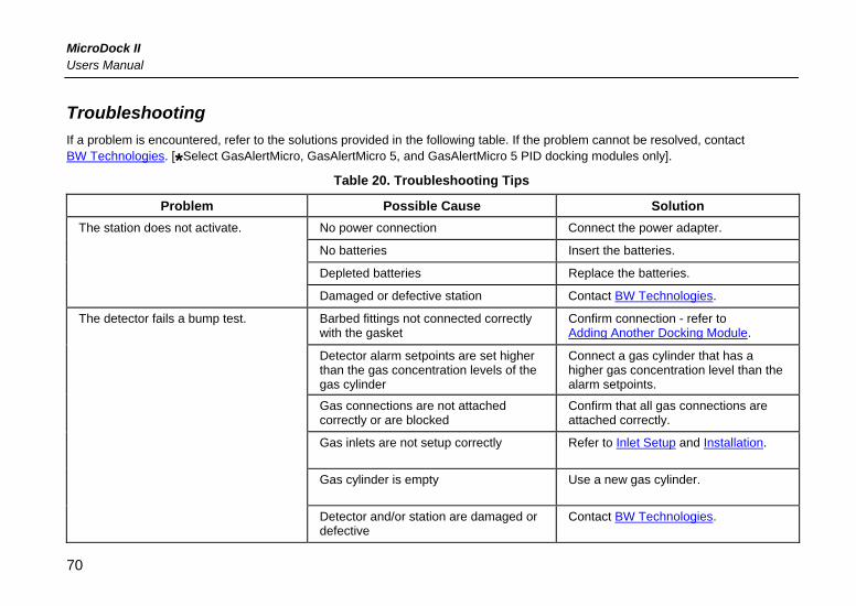
MicroDock II Users Manual
Troubleshooting If a problem is encountered, refer to the solutions provided in the following table. If the problem cannot be resolved, contact BW Technologies. [*Select GasAlertMicro, GasAlertMicro 5, and GasAlertMicro 5 PID docking modules only].
Table 20. Troubleshooting Tips
Problem Possible Cause Solution No power connection Connect the power adapter.
No batteries Insert the batteries.
Depleted batteries Replace the batteries.
The station does not activate.
Damaged or defective station Contact BW Technologies.
Barbed fittings not connected correctly with the gasket
Confirm connection - refer to Adding Another Docking Module.
Detector alarm setpoints are set higher than the gas concentration levels of the gas cylinder
Connect a gas cylinder that has a higher gas concentration level than the alarm setpoints.
Gas connections are not attached correctly or are blocked
Confirm that all gas connections are attached correctly.
Gas inlets are not setup correctly Refer to Inlet Setup and Installation.
Gas cylinder is empty Use a new gas cylinder.
The detector fails a bump test.
Detector and/or station are damaged or defective
Contact BW Technologies.
70
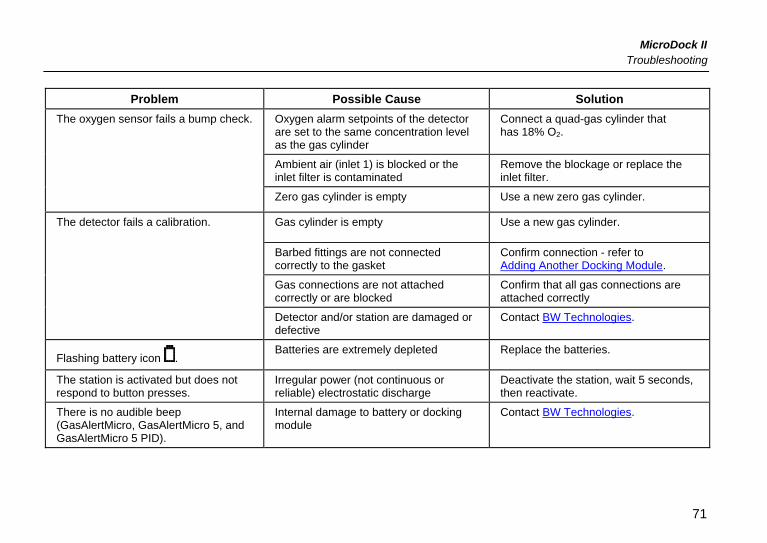
MicroDock II Troubleshooting
Problem Possible Cause Solution Oxygen alarm setpoints of the detector are set to the same concentration level as the gas cylinder
Connect a quad-gas cylinder that has 18% O2.
Ambient air (inlet 1) is blocked or the inlet filter is contaminated
Remove the blockage or replace the inlet filter.
The oxygen sensor fails a bump check.
Zero gas cylinder is empty Use a new zero gas cylinder.
Gas cylinder is empty Use a new gas cylinder.
Barbed fittings are not connected correctly to the gasket
Confirm connection - refer to Adding Another Docking Module.
Gas connections are not attached correctly or are blocked
Confirm that all gas connections are attached correctly
The detector fails a calibration.
Detector and/or station are damaged or defective
Contact BW Technologies.
Flashing battery icon . Batteries are extremely depleted Replace the batteries.
The station is activated but does not respond to button presses.
Irregular power (not continuous or reliable) electrostatic discharge
Deactivate the station, wait 5 seconds, then reactivate.
There is no audible beep (GasAlertMicro, GasAlertMicro 5, and GasAlertMicro 5 PID).
Internal damage to battery or docking module
Contact BW Technologies.
71
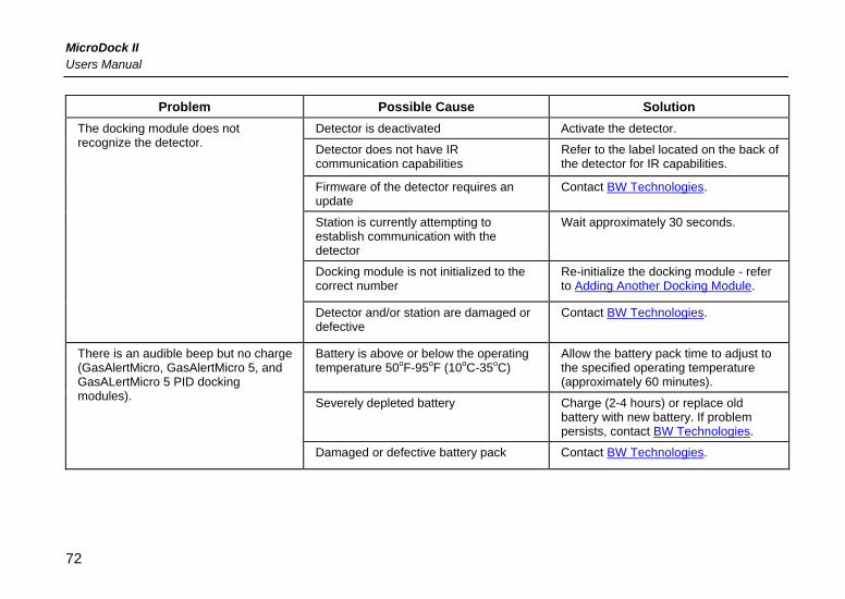
MicroDock II Users Manual
Problem Possible Cause Solution Detector is deactivated Activate the detector.
Detector does not have IR communication capabilities
Refer to the label located on the back of the detector for IR capabilities.
Firmware of the detector requires an update
Contact BW Technologies.
Station is currently attempting to establish communication with the detector
Wait approximately 30 seconds.
Docking module is not initialized to the correct number
Re-initialize the docking module - refer to Adding Another Docking Module.
The docking module does not recognize the detector.
Detector and/or station are damaged or defective
Contact BW Technologies.
Battery is above or below the operating temperature 50oF-95oF (10oC-35oC)
Allow the battery pack time to adjust to the specified operating temperature (approximately 60 minutes).
Severely depleted battery Charge (2-4 hours) or replace old battery with new battery. If problem persists, contact BW Technologies.
There is an audible beep but no charge (GasAlertMicro, GasAlertMicro 5, and GasALertMicro 5 PID docking modules).
Damaged or defective battery pack Contact BW Technologies.
72
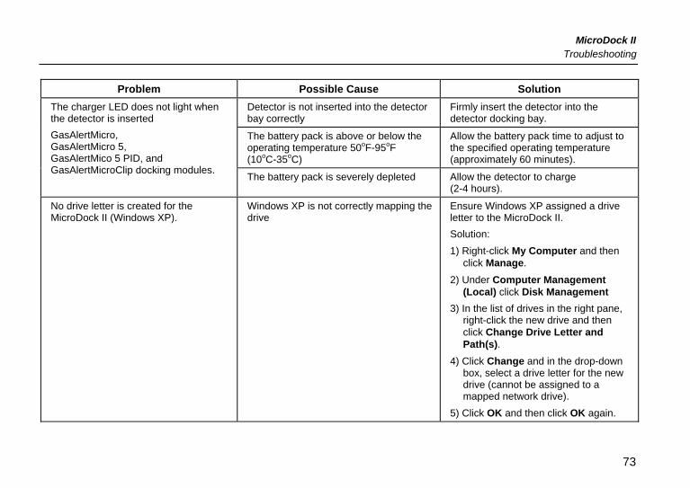
MicroDock II Troubleshooting
Problem Possible Cause Solution Detector is not inserted into the detector bay correctly
Firmly insert the detector into the detector docking bay.
The battery pack is above or below the operating temperature 50oF-95oF (10oC-35oC)
Allow the battery pack time to adjust to the specified operating temperature (approximately 60 minutes).
The charger LED does not light when the detector is inserted GasAlertMicro, GasAlertMicro 5, GasAlertMico 5 PID, and GasAlertMicroClip docking modules.
The battery pack is severely depleted Allow the detector to charge (2-4 hours).
No drive letter is created for the MicroDock II (Windows XP).
Windows XP is not correctly mapping the drive
Ensure Windows XP assigned a drive letter to the MicroDock II. Solution: 1) Right-click My Computer and then
click Manage. 2) Under Computer Management
(Local) click Disk Management 3) In the list of drives in the right pane,
right-click the new drive and then click Change Drive Letter and Path(s).
4) Click Change and in the drop-down box, select a drive letter for the new drive (cannot be assigned to a mapped network drive).
5) Click OK and then click OK again.
73
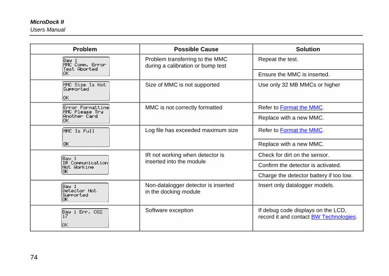
MicroDock II Users Manual
Problem Possible Cause Solution Repeat the test.
Problem transferring to the MMC during a calibration or bump test
Ensure the MMC is inserted.
Size of MMC is not supported Use only 32 MB MMCs or higher
Refer to Format the MMC.
MMC is not correctly formatted
Replace with a new MMC.
Refer to Format the MMC.
Log file has exceeded maximum size
Replace with a new MMC.
Check for dirt on the sensor.
Confirm the detector is activated.
IR not working when detector is inserted into the module
Charge the detector battery if too low.
Non-datalogger detector is inserted in the docking module
Insert only datalogger models.
Software exception If debug code displays on the LCD, record it and contact BW Technologies.
74
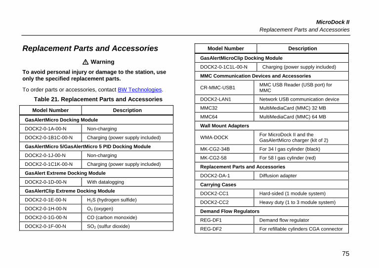
MicroDock II Replacement Parts and Accessories
Replacement Parts and Accessories a Warning
To avoid personal injury or damage to the station, use only the specified replacement parts.
To order parts or accessories, contact BW Technologies.
Table 21. Replacement Parts and Accessories
Model Number Description
GasAlertMicro Docking Module
DOCK2-0-1A-00-N Non-charging
DOCK2-0-1B1C-00-N Charging (power supply included)
GasAlertMicro 5/GasAlertMicro 5 PID Docking Module
DOCK2-0-1J-00-N Non-charging
DOCK2-0-1C1K-00-N Charging (power supply included)
GasAlert Extreme Docking Module
DOCK2-0-1D-00-N With datalogging
GasAlertClip Extreme Docking Module
DOCK2-0-1E-00-N H2S (hydrogen sulfide)
DOCK2-0-1H-00-N O2 (oxygen)
DOCK2-0-1G-00-N CO (carbon monoxide)
DOCK2-0-1F-00-N SO2 (sulfur dioxide)
Model Number Description
GasAlertMicroClip Docking Module
DOCK2-0-1C1L-00-N Charging (power supply included)
MMC Communication Devices and Accessories
CR-MMC-USB1 MMC USB Reader (USB port) for MMC
DOCK2-LAN1 Network USB communication device
MMC32 MultiMediaCard (MMC) 32 MB
MMC64 MultiMediaCard (MMC) 64 MB
Wall Mount Adapters
WMA-DOCK For MicroDock II and the GasAlertMicro charger (kit of 2)
MK-CG2-34B For 34 l gas cylinder (black)
MK-CG2-58 For 58 l gas cylinder (red)
Replacement Parts and Accessories
DOCK2-DA-1 Diffusion adapter
Carrying Cases
DOCK2-CC1 Hard-sided (1 module system)
DOCK2-CC2 Heavy duty (1 to 3 module system)
Demand Flow Regulators
REG-DF1 Demand flow regulator
REG-DF2 For refillable cylinders CGA connector
75
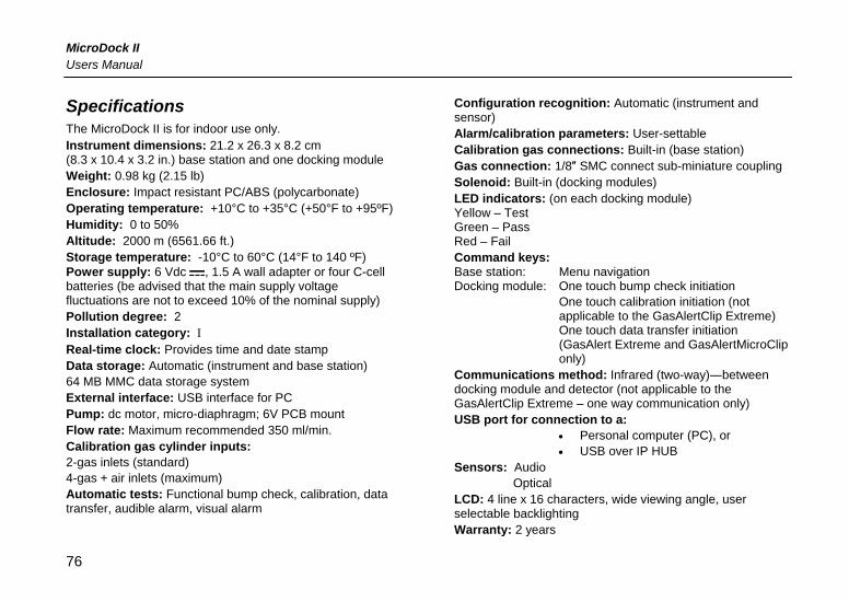
MicroDock II Users Manual
Specifications The MicroDock II is for indoor use only. Instrument dimensions: 21.2 x 26.3 x 8.2 cm (8.3 x 10.4 x 3.2 in.) base station and one docking module Weight: 0.98 kg (2.15 lb) Enclosure: Impact resistant PC/ABS (polycarbonate) Operating temperature: +10°C to +35°C (+50°F to +95ºF) Humidity: 0 to 50% Altitude: 2000 m (6561.66 ft.) Storage temperature: -10°C to 60°C (14°F to 140 ºF) Power supply: 6 Vdc , 1.5 A wall adapter or four C-cell batteries (be advised that the main supply voltage fluctuations are not to exceed 10% of the nominal supply) Pollution degree: 2 Installation category: I Real-time clock: Provides time and date stamp Data storage: Automatic (instrument and base station) 64 MB MMC data storage system External interface: USB interface for PC Pump: dc motor, micro-diaphragm; 6V PCB mount Flow rate: Maximum recommended 350 ml/min. Calibration gas cylinder inputs: 2-gas inlets (standard) 4-gas + air inlets (maximum) Automatic tests: Functional bump check, calibration, data transfer, audible alarm, visual alarm
Configuration recognition: Automatic (instrument and sensor) Alarm/calibration parameters: User-settable Calibration gas connections: Built-in (base station) Gas connection: 1/8″ SMC connect sub-miniature coupling Solenoid: Built-in (docking modules) LED indicators: (on each docking module) Yellow – Test Green – Pass Red – Fail Command keys: Base station: Menu navigation Docking module: One touch bump check initiation
One touch calibration initiation (not applicable to the GasAlertClip Extreme) One touch data transfer initiation (GasAlert Extreme and GasAlertMicroClip only)
Communications method: Infrared (two-way)―between docking module and detector (not applicable to the GasAlertClip Extreme – one way communication only) USB port for connection to a:
• Personal computer (PC), or • USB over IP HUB
Sensors: Audio Optical
LCD: 4 line x 16 characters, wide viewing angle, user selectable backlighting Warranty: 2 years
76
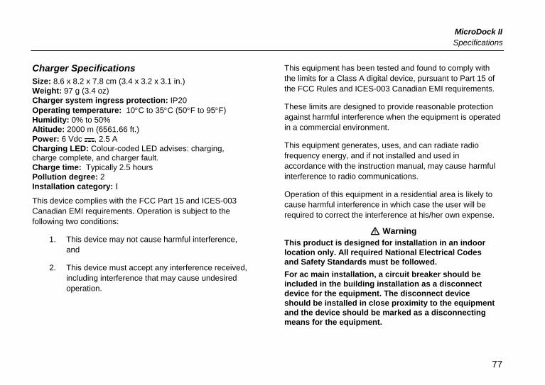
MicroDock II Specifications
Charger Specifications Size: 8.6 x 8.2 x 7.8 cm (3.4 x 3.2 x 3.1 in.) Weight: 97 g (3.4 oz) Charger system ingress protection: IP20 Operating temperature: 10°C to 35°C (50°F to 95°F) Humidity: 0% to 50% Altitude: 2000 m (6561.66 ft.) Power: 6 Vdc , 2.5 A Charging LED: Colour-coded LED advises: charging, charge complete, and charger fault. Charge time: Typically 2.5 hours Pollution degree: 2 Installation category: I
This device complies with the FCC Part 15 and ICES-003 Canadian EMI requirements. Operation is subject to the following two conditions:
1. This device may not cause harmful interference, and
2. This device must accept any interference received, including interference that may cause undesired operation.
This equipment has been tested and found to comply with the limits for a Class A digital device, pursuant to Part 15 of the FCC Rules and ICES-003 Canadian EMI requirements.
These limits are designed to provide reasonable protection against harmful interference when the equipment is operated in a commercial environment.
This equipment generates, uses, and can radiate radio frequency energy, and if not installed and used in accordance with the instruction manual, may cause harmful interference to radio communications.
Operation of this equipment in a residential area is likely to cause harmful interference in which case the user will be required to correct the interference at his/her own expense.
a Warning This product is designed for installation in an indoor location only. All required National Electrical Codes and Safety Standards must be followed. For ac main installation, a circuit breaker should be included in the building installation as a disconnect device for the equipment. The disconnect device should be installed in close proximity to the equipment and the device should be marked as a disconnecting means for the equipment.
77

User Manual
MicroDock II
Automatic Test and Calibration Station
D5617/4 EnglishiERP: 122293
© 2006 BW Technologies. All rights reserved. Printed in Canada.
All product names are trademarks of their respective companies.