Embed Size (px)
Citation preview

MICROFICHE REFERENCE LIBRARY
A project of Volunteers in Asia
Construction Manual for 12PU350 and 12PU500 Windmills
by Niek Van de Ven
Pub1 ished by:
Stichting TOOL Entrepotdok 68A/69A 1018 AD Amsterdam THE ~dSThERLANDS
Available from:
same as above
Reproduced by permission.
Reproduction of this microfiche document in any form is subject to the same restrictions as those of the original document.

RUCTIQN OF 12 PUSS0 AND 12 PU500 WINDMILLS RY NIEK VAN DE VEN
0 C 1982 NIEK ‘CAN DE VEN

Acknowledgement
The Netherlands assistance in the windmill projects in Ghazipur and Allahabad
officially stoppa at the end of March 1981. It was recognized by the project
management committee that the experiences of the experts in these projects
should be recorded. Finally it was agreed that the financing of this activity
took place trough the Steering Committee Windenergy Developing countries (SWD).
This is a government financed organisation promoting the interest for wind energy
in developing countries and aims at helping governments, institutions and private
parties in the Third World with their efforts to utilize wind energy.
The author is very gmteful to all parties concerned that the experiences could
be materialized in this publication. It is hoped that it will contribute to the
extention of development in many countrres.
NIEK VAN DE VEN

TOOL is a Dutch foundation participating in the global process of renewable development and application of socially appropriate technologies.
The broad objective is to promote greater freedom for groups which are deprived of full opportunities for local, self-programmed and self-sustained development.
The stmtegy is to provide and support information resource links among the pmctitioners, users and generators of appropriate technology for development.
T’le opemtions of TOOL are designed to match need and resource: - technical advice and support - research and development - publications - documentation systems and services - applicstion projects - education and training - organisational linkages.
WOT is a non-profit organisation at the Twente University of Technology and gives technical advice in the field of wind energy, solar energy and water supply. The broad objective is to improve the position of the weaker sections in society and the advice should be appropriate to the local situations and circumstances. To support the technical advice the WOT has a testing field where various designs are being developed and tested. The WOT is mainly a voluntary organisation and consists mainly of students of the university. Several staffmembers take care for the administmtive and technical support.

CONTENTS
0. Introduction
we
0.0
1. The 12 PU 35C'amd 12 PU 500 windmill for irrigation
1.1 Capacity of the windmill 1.1
1.2 The well and the storage tank 1.4
1.3 Required skill, equipment and materials 1.6
2. Tower construction
3.
3.1
3.2
3.3
3.4
Head construction
The front section 3.1
The tail construction 3.5
The tail vane and help vane 3.6
The safety device 3.7
4.
4.1
4.2
4.3
4.4
Moving parts
Mill shaft bearings 4.1
Crank and crank pin 4.3
Connecting rod and bearing bushes 4.4
Cross head and pump rod guide 4.5
5. Rotor
5.1 In- and outside rings 5.2 Building the rotor frame 5.3 Blade supports 4.4 Blades
5.1
5.2
5.6
5.7
6.
6.1
6.2
62
Piston uump
The functioning of the pump Preparation of the steel cylinder Foot valve arrangement and pre-machining of the piston
6.1 6.4
6.5

6.4.1 The top section 6.6
6.4.2 The bottom section 6.7
6.4.3 The piston 6.8
6.5 Final assembly 6.9
7.
7.1 Erection of the tower 7.2 Installing the head construction 7.3 Installing the rotor 7.4 Installing the pump 7.5 Maintenance of the windmill 7.5.1 The overall structure 7.5.2 Tower 7.5.3 Head construction 7.5.4 Moving parts 7.5.5 The rotor 7.5.6 The piston pump 7.6 Monitoring of the windmill performance
Installing the windmill
Material requirement; 12PU350 Appendix I
Material requirement; 12PU500 Appendix II
7.2
7.3
7.5
7.6
7.9
7.9 7.10 7.11
7.12 7.13 7.13 7.14

0.0
Introduction
No doubt a lot of research is going on nowadays in the field of windnill technology: fuel prices are still driven up day-by-day changing the economic feasibility of many machines and equipment. Moreover we become more and more aware that the current fuel resources like gas, coal and crude oil are rapidly depleting while their exploitation encounters increasing practical constraints.
This brief introduction is not meant to create the impres- sion that the application of wind energy will be the final answer to future energy problems. On the contrary: the common energy consumption per head in the West has reached such a level that for example in the Netherlands thousands of huge windmills are to be installed at the windy shore of the country, necessary just to cover a few percent. (say 5 or so) of the actual need of energy. Moreover it will be doubtful whether the initialenergetic investment in such an enterprise will ever be "paid back" during the actual lifetime of such remarkable generators.
Does it mean that there is no future for the windmill? Of course there is, which can be illustrated by the fact that in the past and still at the present windmills proved to serve their purpose very well as far as limited power con- -- version is concerned, especially in places where power distribution is poor, fuel is too expensive or even not available at all. In spite of the recent low fuel prices the windmill has never been defeated totally and as a mat- ter of fact a great revival of the windmill is at the door- step now since the use of its competitors becomes less at- tractive due to scarcity of the conventional Fuels and their price politics in particular.

0.1
The latter development (though partly expected,but not fully foreseen) has strengtkened some people who have taken up the windmill technology for further development and espec- ially concerning its adoption in local circumstances. This manual resulted from the developing process of windmills which was initiated by experts of the Dutch TOOL - foundation in close cooperation with the Organisation of the Rural Poor (ORP) in Ghazipur andthe Allahabad Polytechnic Allahabad (U.P.) India.
.
From December 1977 on a g-bladed smping &it of 500 cm rotor- dia (12 PU 500) evolved overtiiere and in later stages also designs of the 12 PU 350, 12 PU 250 and 12 PU 700 have been derived. !Ihese windmills are supposed to be fabricated locally with a minimum of advanced equipment.
This building manual deals with the 12 PU 350 and 12 PU 500 windmills while the 12 PU 250 and 12 PU 700 are still under development.

1.0 --- / Y E
i

--.. - -_- . ^ “.. :i
A 12 PU 500-windmill being installed for drinking water supply (February 1980, Gohri near Allahabad, U.P. India).

1.1
1. 5e 12 PU 350 and 12 PU 5CCI windmill for irrigation
5ese windmills have been developed especially for irrigation purposes. They operate in windy places and convert a certain part of the offered windenergy into mechanical power. 5is mechanical power is led via a crankmechanism to a single- acting piston pump, which lifts the water from shallow wells or tube wells to ground level. Generally the lifted water is stored in a basin in order to save it during day-time so a regular flow can be obtained for an increased efficiency. Usually the irrigation is carried out during sunset, since the evaporation of the irrigation water is less than in daytime. The amount of irrigation water needed depends on the climatological conditions, the soil structure and the crop pattern, so the size of the command area is restricted by these and the capacity of the windmill.
5e construction of the windmill is that simple that it can be prefabricated by blacksmiths using the materials and equipment which are available locally in India. Maintenance is restricted to greasing some essential moving parts from time to time, which can be carried out by the owner (farmer) himself. !I!he windmill is secured automatically against storms: if severe storms appear the windmill turns out of the wind and will remain in that position till it is reset manually. Bkanwhile it is a great opportunity to inspect and lubricate the moving parts.
1.1. Capacity of the windmill
Since the capacity of the windmill depends on the availability of the wind the latter is very important in order to make esti- mates of the output. merefore it is preferredto study the wind data of the area which have been measured in former years. Probably these data can be obtained from local. institutes or

1.2
airports. The essential thing of these winddata is the duration in hours of certain windspeed ranges during a year in the form of histograms, in order to estimate the capacity of the windmill. The figure shows an example of these histo- grams.

1.3
Since there are various power-losses due to some proper- ties of the windmill-pistonpump combination the extracted windpower will be converted partly into a nett delivered water flow. Next figures show the quantity of water delive- ry in litres per second in case of four different elevation heads ( 5 m, 10 m, 15 m and 20 m) if the windmill concerned is fitted with the standard piston pump (see chapter 6).
12 PU 350 12 PU 500 c
uz
% l \
84 4&E
0 I l S4#OT8
me adjustable crank radius provides three different stroke volumes of the piston pump, so the windmill can be loaded suitably within the actual circumstances. It will be evident that a higher chosen value of the crank radius will influence the starting wind speed and the output as well.
Considering the wind data obtained the monthly number of hours of certain ranges of wind speeds (O-1 m/set, 1-2 m/set, 2-3 m/ sec. etc.) are calculated: this is done for all the ranges up to 12 x/aec. since the windmill stops operating above this va- lue of wind speeds due to the automatic security device. In relation with the flow-windspeedgraphs the expected water delivery per month can be estimated. Since fluctuations in nind speed and wind direction will cause a lower result, the estimated monthly delivery can be multiplied by a factor 0.7

1.4
or 0.8 in order toachievea more valid estimation.
IJow it is possible to define the crop pattern and the maxi- mum size of the command area which will be under windmill irrigation.
1.2. The well and the storage tank
One has to be sure, whether the capacity of the well will be sufficient with regard to the expected peak windmill capacity. As far as just a shallow well is going to be ap- plied the windmill pump will start sucking air if the well is not able to deliver the amount of water needed. !&is ef- fect will not harm the pump; only airbulbs will be trans- ported through the water column which is kept in the pump and delivery pipe. But if a tube-well is gVoverdra~>~lg, much sand will be transported by the lifted water and a quickly worn out pump will be the result due to aggressive sand particles. Therefore one has to be sure, whether a tube well can deliver the peak capacity of the windmill.
Generally the pump section is installed near or below the water level in order to maintain a low suction head. In practice this suction head must not be higher than appr. 7 m.- in order to prevent cavitation.
Applying a narrow tube-well (e.g. 4") in combination with an existing shallow weEl (see chapter 6) sufficient space is available for a proper installation of the tube well section near or even below the static water level. In this case the existing well casing provides a solid foundation for the wind- mill and pump anchors. The exhaust aperture of the pump is pre- ferably situated in such a way that people can easily do the wash or tap some (drinking) water, since this will be done definitely. A simple accomodation, &ich is built from bricks, will prevent people from damaging the outlet pipe. Also a struc-

1.5
ture of bricks is demanded for an erosion-free guidance and a proper entrance of the water flowing into the tank.
/ :
- \
,I,’ .
/
_’ c - , . ‘.I ,,‘, .
,’ “._,
Usually the tank is composed of walls of appr. 1 m high, which are built from the surrounding soil. The contents of a storage tank amount from 50 to 150 m 3 depending on the expected need and area available tiich can be suita- bly occupied by the tank.

I.6
If the soil has sufficiently high clay content no extra provisions are required with regard to the expected see- pages, but if these seepages are not to be neglected it is advisable to plaster the mud-walls with bricks. Under certain conditions the application of a plastic-foil will decrease the seepage definitely.
Due to erosion the unmasoned walls will be damaged in the environment of the water-line which can be prevented by growing grass in these particular places. Of course an overflow will be necessary in connection with the erosion mentioned before.
To release the water out of the tank an outlet pipe, fitted with a valve, will serve the purpose but the disadvantage is that people or playing children may open the valve and release the water which flows to the field uncontrolled. Using a 23"hose as a siphon the released water can be tap- ped in any place of the tank and is guided into one of the several irrigation-ditches. As mentioned before this irri- gation is carried out during sunset in order to limit the evaporation of the irrigation-water. In certain cases fish-rearing or growing waterlilies (for cattle-feeding) can be attractive in order to make the to- tal windmill installation more profitable.
1.3. Required skill, equipment and materials.
5is simple windmill construction can be realized easily with the local skills, machines and materials. 5erefore the re- quired machines are restricted to a turning-lathe, a drill-
ing machine and an electrical weldingset. The construction materials consist of angle iron, flat iron, gas pipe, ball bearings, leather, some wooden parts, bolts, nuts and washers.

WA.UT~W~MSS :OuFRPiff NOT LESS THAN 3 5 WW

.
In various developing countries such equipment and materi- als are available everywhere and due to the simplicity of the design no advanced engineering is required. However, some of the labourers have to be trained in reading drawings (here: English), handling the machines and carrying out some measurements, while others have to do the simple things like cutting, painting etc. In the next chapter of the booklet the mostessentialmatters, with regard to measurements, order of machining and con- structing are fully described.
Generally first all the materials are purchased and trans- ported to the workshop. There the production of the main- parts starts according to the sequence of the next chapters (tower, headconstruction,etc.). !i!he prefabrication of all these parts takes about 200 man- hours (100 sk2lled and 100 unskilled manhours appr.), de- pending on the local circumstances like shortage of mate- rial, power-cuts etc. After completing the mainparts they are transported to the site (see chapter 7), where the wind- mill will be erected.
In case of large scale production of the 12 PU 350 and 12 PU 500 windmills their production will be facilitated and stream- lined by means of the application of welding fixtures, drill-
ing guides and manipulators. Some small alternations in the designs are introduced as well in order to optimize the trans- portation of these remarkable products.

2.1
2. The towerconstruction
The tower is the simplest part of the windmillconstruction. It can be fabricated in a few hours only.
First two tower-half are composed as follows. The angles 2 are positioned on the floor in such a way, that the top of the towerhalve clamps around the 4" towerpipe 1.
By means of chalk-marks thepositionof the angles 3 , 7 and 9 and flats 4 , 5 and 6 are marked and these parts are
welded to the tower legs. Do not forget to drl.11 the holes into the angles 3 for the connection of the platform planks. I'?ow the angles 8 are positioned and welded. Some scrap, e.g. angle iron, is welded to the bottom side of the tower legs, provid'cng simple anchors.
After completing the two equal halves,the tower is composed on the floor while the two tower halves are kept upright. See that the tips of the two tower halves just touch each other and secure this position temporarily by means of small spot-weld4ngs. flow the angles 7 and 8 are positioned and fielded as far as possible and the tower construction becomes more and more rigid. In this'phase the temporary spot-weldings in the tower top can be opened and the tower pipe section can be shifted in.

2.2
This section is composed by the tower-pipe and the four flats 13 by welding the flats exactly straight to the bottomside
of the pipe. See that the flats 13 are inclined sufficiently so that the cross fits exactly into the inside of the tower
in the plane of the four angles 7 .
Now the entire tower pipe section is shifted into the tower positioned precisely and welded to the inside of the tower legs. The upper section is surrounded by the ends of the
tower-legs,lil order to ensure a strong and reliable connection
eight cut pieces of flat 14 are welded in as filler metal. These triangular pieces can be cut simply from flat.
ITow the tower has become strong enough to handle it by rolling it from side to side in order to finish all the weldings. See that the top of the tower pipe will not be damaged during these transactions since the headconstruction should fit properly around this pipe (see next chapter).
All the carbon of the weldings can be removed and the entire structure must be cleaned by brush before the tower is pain- ted (first primer).
'he holes in the planks are defined and just drilled: the planks will be mounted to the tower later on if it is erec- ted on the site. This is done in order to prevent damage to the platform during transport.

_ rti. .- .z.-- .-rm!- -.. -4
---- --.-~~~~. --I 849 .-. - --_- -..- ---mY. --- 488 ---.---. ~----
- -- --- .-_ ..-_ n4L- - - m*x~~,~ ----.- -- -Mz.-
E
u ‘0
I

. .

3.1
3. The head construction
The head construction is the most important part of the en- tire windmill construction. It provides a suitable framework for carrying the rotor construction and the moving parts and moreover it contains the automatic security device.
. In mounted condition the head construction can rotate around the tower pipe by the steering function of the windvane. The latter keeps the wind-wheel in front of the wind unless the windmill is in secured position; then the windwheel is kept out of the wind automatically,
If the windspeed exceeds a certain value the auxiliary vane unlocks the front part of the head construction from the tail structure and the head turns approximately 75 degrees out of v5nd backwards. In this position the entire windmill is secured against severe damage caused by storms.
The head construction is composed by angle-irons and flats, which are assembled quite accurately. Machining is just res- tricted to drilling some holes.
Generdly the production is started in the following sequence: frontsection, tail, vane and security device and it will be dis- covered that a lot of time will be spent in obtaining a smooth operation of the security device,
tion
This section is rather difficult to build and the right se- ence of composing the parts is important. First three sec-
tions are prefabricated in order to simplify %e composition:

3*2
section 1:
Angles 7 will surround the towerpipe and the length of these is veq important. Two angles 7 are welded to angle 11
and this section defines the position of the other two angles 7 in section 2.
section 2:
Two angles 7 are welded to the two angles 5 ,which are po- . sitioned in parallel. See that the width of the two composed angles 5 near the welded parts 7 does not exceed the out- side tower pipe diameter. Later-on i-l kll become clear, that this measure is rather essential with regard to the fitting . of the head construction over the tower pipe.
section 3:
Wow angles 1 and 2 are composed. It is preferable to drill the holes in the angles 1 first ; the pitch is taken over from the bearing hwuses,

3*3
Now the moment comes to assemble the three sections. First section 3 is connected to the top of section 2 by spotweldings according to the drawings. To make both sections perpendicu- lar to each other the angles 3 can be positioned and spot- welded after the top of each is inclined to 60 degrees . It is essential to apply spotweldings first, since many mis- takes can be made in this phase, so correction can be carried out easily,
@i Q a
How the section 1 will be built in in such a way, that the structure fits properly around the tower-pipe. merefore it is preferable to use a piece of 4" pipe with the equal out- side measure, which is enclosed in the framework temporarily. The angles 6 , 12 and 13 are positioned and fixed by means of some spotweldings after the required holes of the pivot are determined and drilled. !&e pieces of flat 26 have to be positioned and welded after which the holes are drilled. It should be checked whether your drilling machine reaches sufficient height for this workpiece. If not, better drill the holes first in the angles before the latter are welded in the head construction. Besides an other kind of tail-pivot arrangement will be suitable which is described further on%

3.4
With regard to the positioning of the angles 6 there is no need to incline the ends on the frontside since the ver- tical flanges have an overlap with the angles 3 . Do not weld yet near the overlap where angle 15 will be position-
ed and welded later on. Angles 4 are jointed; also here the vertical flanges will overlap angle 6 so an inclination of it will not be re- quired either. The fit of angle 15 between angles 3 may not be quite proper, but since this part of the frame is rather elastic angle 15 can be hammered in or clamped tem- porarily during its positioning. All the spotweldings and connections can be finished now and a strong and rigid frame is obtained. An extra reinforcement is provided by welding in the flats 24 and 25 .
It will be clear, that the weight of the entire head construc- tion and the pumprod forces are going to be carried by the
edge of the tower pipe and there in particular some wearing may be expected after some time of operation. Therefore two wearing flats 21 are spotwelded at the inside of the angles
7.
The fit of the head construction over the tower pipe is checked and corrected by filing, since change in measure is to be expected-after the welding procedure. Moreover the urn- roundness of the 4" tower-pipe may result in a seising fit

3.5
at some positions of the headconstruction so the need of filing (or grinding) may be expected. Some clearance of approximately 0.5 mm between the surroun- ding angle frame and tower pipe is acceptable.
If a rod is applied for the hinge according to the drawings the distance-plates 26 are made and welded to the head construction. As mentioned before there is an easier way to realize the pivot for the tail. Instead of drilling,two suf- ficiently strong and long bolts are welded in these pla-
ces. The rod 32 and two plates 26 are superfluous then, while the number of the rather big holes, which have to be drilled, is restricted to two only.
Now just the frame work of the front part of the head con- struction is finished: later on the mechanism of the safe- ty device will be assembled, after completing the tail construction
3.2. The tail construction
The upper-tail angle 17 is reinforced over a specific length at the frontside by means of the extra angle 16 .
Both are connected by means of a number of weldings with a length of 25 mm and a mutual pitch of appr. 150 mm. Then the hole for the pivot is drilled through the reinforced section in such a place that the front part of this double tail an- gle has a 5 mm overhang of the angle 5 of the head construc- tion. This is necessary with regard to the unlock system of the safety device (see next paragraph). The pivot hole in the lower tail angle is also drilled.
Now the head construction is put in vertical position while the upper tail angle is connected by means of the pivot and is kept horizontally The end of the lower tail angle 18 is bent over after first cutting a triangular opening in the upright flange. If the de- sired angle is obtained the remaining cut can be closed by welding.


3.7
This is achieved by hammering these edges over a rod or angle which provides a temporary gauge.
One will discover that the vane became very rigid without in- creasing its weight. Now the vane is laid down on the floor and the tail is positioned on it and the holes can be taken over by marking or drilling directly if a hand-drilling-machi- ne is available.
.
As mentioned before the profiling of the small help vane is done simply by hammering profiles into it diagonally. There- fore the four corners of the sheet are cut first, so that the diagonals as well as the edges can be hammered.
3.4. The safety-device
Actually there are two devices: first the spring-adjusted- help-vane-mechanism initiates the security movement by ope- ning the lock between the head and the tail. Secondlsatoothed handle prevents that the tail will turn back and keeps,it lockeil a% the end of the movement which is
really necessary during heavy storms.

‘, .
3.8 ,
The help-vane-lock-mechanism is made as follows: Bolt 37 is welded to the horizontal flange of angle 6 in such a way that this bolt can act as a simple pivot for angle 70 . In mounted condition the edge of the horizontal flange of angle 10 just touches the edges of the upright angles 5 while the pivot hole is drilled in such a place that the end at lock-side does not protrude from the frame. Rcw a filling piece is required between the bolt head of
37 and angle 10 so that the lock, which will be made in the horizontal flange of the latter, csn engage the upper tail angle 17 (See drawings). Generally one nut will serve this purpose.
In order to reZnforce the suspension of the help vane arran- gement a second pivot has to be created: an extra long bolt applied for the fixation of the rear-bearing house provides this. Flat 23 is drilled and bent and welded finally to

angle 10 while the latter is kept horizontally. It is evident that the bearing house has been mounted already ( temporarily*or permanently) in order to achieve a proper- ly positioned help vane structure.
The most accurate job is making a smooth operating lock, which keeps the upper tail angle 17 pressed to angle 5 of the head construction in locked position. Therefore a simple cut-out is made by sawing and filing which will not be deeper than 5 mm(!) while the sliding edge of the cut is inclined a little. This inclination is done in order to obtain a wed- ging-effect resulting in a clearance-free lock between head and tail. Inclination of the run-on side of the lock is required for smooth manual handling if the windmill will be put into ac- tion later on. The movement in rotation of the help vane structure is li- mited to a maximum of 10 mm by the top of the bolt 35
which provides a limit stop and a possibility of spring- adjusting as well.
--
First the head of this bolt is welded perpendicularly to the small angle 14 and this section is positioned and welded in the head construction so that the help vane struc-

3.10
ture can just rotate within its permitted travel of 10 mm. Generally a suitable spring is obtained from the valve ar- rangement of a diesel- or petrol-engine. To centre the spring between the adjusting nut 31 and angle 10 two diffe- rent washers are welded to these (see drawing).
The holes can be drilled in angle 10 according to the gi- ven positions in the drawing for mounting the help vane by means of H 6 (W p) bolts and nuts. The unlock mecha- nism is finished now, proper adjustment of the spring is carried out after assembling the entire windmill on the site.
Now the second part of the securing-mechanism is goPng to be assembled. First the limit-stop-angle 9 is positioned and welded to angle 6 of the head so that the measured angle between head and tail amounts to appr. 75 degrees. Pivot bolt 37 is welded with its head to the inside of angle 6 of the head construction and the pivot-hole is drilled in flat 27 . The latter is welded to angle 8
according to the specifications given in the drawings, but the flat 22 is not yet connected. Now this section is fixed temporarily to its pivot. Later on the right position of the toothed handle 22 will be defined. First flat 21 is positioned to the upper tail-
3.11
angle 16 with its sliding on line of the edge of angle 6 .(see drawings) and now flat 22 (still untoothed) is
positioned at the horizontal flange of 8 in such a way that the edge of flat 22 always touches the edge of 21
See that angle 8 moves free of the inside of angle 6 so that the spring, if it is mounted later on, can always maintain a pressed contact between 21 and 22 even if the latter is toothed ! The complete handle is taken out now and the teeth can be made accurately by grinding or filing (the direction of the teeth is taken into account!).
After this is done the handle is built in again; the hole for the spring-loaded bolt 36 is drilled and the latter is mounted, including spring, washer, etc. The mechanism is checked now. No clearance is petiitted in it. In secured position tail and head both should be kept strongly together, in order to avoid their mutual move- ments during storms.
I@ means of filing or grinding a self-wedging lock is ob-
tained which keeps the head and tail together without clearance. If this is not succesful and the clearance persists,a filling between stop- angle 9 and the tail can be applied. Generally a small piece of sheet will serve this purpose.

3.12
The other two flats 21 will complete the entire securi- ty-mechanism. These flats surround the handle in order to prevent that The lever is bent down during transport or is operating in a wrong place.
The total head construction is finished now and ready for painting.

-. __~*Xi _--- ---I -_. __“.-
.*- .“-- -. .--~-.,1X_
_ ii I-

composing a?-ld spot welding the head
mnst-metion is
facilitated by
apphying a welding
fixture
checking the fit of the heed3 over t
tcmer pipe.

4.1
The rotation of the mill shaft is converted into an up- and down movement of the pumprod by means of a crank-connecting rod-mechanism. The crosshead is guided by the inside tower- pipe so if the head construction turns around the towerpipe, due to a change of wind-direction , the cross head, pump rod and piston as well will also turn.'
The mill shaft rotates in ball bearings, while both the crank- pin bearings and cross-pin-bearings are made of nylon. If no nylon is available bronze will be a good choice, but still nylon is preferred with regard to lubrication and maintenance. The cross head is made of wood since field testings proved that its lifetime will be remarkably long depending of course on the applied lubrication.
Generally the gas pipe which is applied as tower pipe has a seam inside which cannot be removed easily,so it is fitted *with an insert in order to provide a smooth guidance to the crosshead. Tfiis insert can be realized by cutting a strip from a PVC-pipe, so that the circumference-measurewill be little less than the one inside the tower pipe. !Fhe opening just provides enough space for the seam and the latter is countersunk now. Cn its bottom side a M 6 (W 4') bolt locks this PVC-insert in axial sense (see drawings).
!ITwo kinds of load actuate on the two bearings. It IS assu- med that the front bearing carries the radial load due to the total weight of the rotor and the axial forces (thrust- load) caused by the windpressure acting-on the rotor. The

4.2
rear bearing carries the alternating crank forces. It Will be clear that the best quality of bearings and bea- ringbushes (sleeve-type) will be applied. If a proper fixation of the bearings to the shaft is not assured en- tirely, the shaft will start rolling and shifting in the bearing bushes de finitely. This rolling will increase after some time of operation, while the shaft shifts backwards due to the thrust and the sharp edges of the rotorhub (angle irons) will scrape at the front of the cast-iron bearing house. A few thousand revolutions are sufficient to destroy this bearing house completely 'and the ball bearing (due to the scraping-dust).
This is prevented by locking the bearing bushes to the shaft by means of some small spot weldings (!) so that the shaft cannot roll and shift. Proper positioning of the bearings with regard to the axial clearances between the bearings and the inside edges of the bearing houses iiefineswhichbearing is going to carry xhichload. With regard to the bearings themselves:self-aligning bearings of double roller type are most attractive provided one goes for the best quality. Single rollers can be loaded more due to the bigger contact surface of the balls but extra attention has to be paid to the alignment. In many cases complete one-piece bearing blocks are available which are self-aligning and of excellent quality. Since the rear bearing is loaded by reciprocating forces the bearing house top also has to carry some load. A crack of this cast iron top may be occur then which leads

4.3
to a disastrous damage of the rotor, because it will tum- ble forward and hit the tower ! To prevent this a simple security device is applied which supports the housing in carrying upwards forces. Therefore bolts 24 have to be extended which can be ob- tained simply by v,elding nuts to the heads of bolts 25 resulting in easily removable extensions.
4.2. Crank and crank pin
The crank is composed of flats 11 , 12 and 17. First the holes are drilled in flat 17 and the latter is positioned according to the drawingsand spotwelded perpendicularly to the rear end of the mill shaft.
How the flats 11 are positioned planparallelly so that the inside measure is equal to the width of the applied crank- pin nut. This nut will be trapped now between the flats 11 preventing that it will turn during fastening the crsnk pin lateron.It will be evident that inside weldings are not per- mitted near the places, where the nut will be positioned in future.

4.4
During finishing the weldings one will see that 17 will remain perpendicular to the shaft while the weldings between flats 11 and the shaft are made double. Now flat 12 is bent, positioned and welded. The latter will be necessary in carry- ing over the generous forces.
It will be clear that the surface of flat 17 should be per- fectly plane in order to achieve a proper bearing joint with the collar of a crank bush. As a matter of fact all alternating forces and momentsacting on the bush are supposed to be transmitted via this collar to the crank plane merely by means of friction. One can imagine what is going to hap- pen if the central crank bolt runs loose, so a proper tighte- ning of it is most essential.
4.3. Connecting rod and bearing bushes
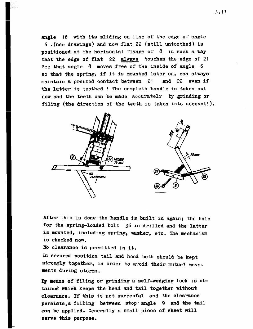
The essential thing is to weld two bushes 5 mutually paral- lel to the flat. 14 . This is achieved by using a simple wel- ding help device which is composed of an angle and two bolts with nuts and washers ( or flats). These bolts are welded
4.5
at the needed pitch to one of the flanges of the angle and now the bushes 5 can be fixed parallel while flat 14 is kept between them and welded. After it is taken out flats 13 will be positioned and welded providing extra strength to the connecting rod.
!I!he nylon bearing bushes fit with a slight oversize into the welded bushes of the connecting rod but the inside measure still will be oversized with regard to the fit over the crank pin. The unroundness of the bushes,caused by the welding procedure, does not affect a smooth function of the bearings which fit around the pin with a clearance of 0.2 - 0.3 mm in radial sense. An axial clearance of appr. 1 to 2 mm is permit- ted and usual.
For lubrication only the top bush is furnished with a lubrica- ting hole which ends up in the groove between the two nylon bearing bushes. At bottom side the nylon bearings will be situated in oil since the cross head is oil-containing.
4.4. Cross head and pump rod guide
!l!hese parts are made of wood so expansion is to be expec%?d due to oil absorption. Generally the rough material is kept in (ex- pired) oil durwg a few days so that the wood will be soaked and expanded if it is machined.

i’ .
4.6
!Che simplest way in making the cross head is to start with drilling the central hole but so that the pump rod (gas pipe) fits into it heavily. Actually there is no need to make this hole through the crosshead. The depth as is stated in the drawings will be sufficient for a proper fixation of the pump-rod.
Now a piece of gaspipe is forced in temporarily which pro- vides a mandrel in order to fixate the rectangular block to the chuck of the lathe-machine. The other end is supported by the centre.
First the outside diameter is turned at the right measure so that a slide fit is obtained in the (inserted) tower pipe. !t!hen the centre is removed and a central hole is drilled and turned carefully at the top of the cross head. !the lathework is done now and the mandrel is removed.
Now the holes for the crosspin are drilled exactly through and perpendicular to the centre line of the cross head. The fit of the cross pin into these holes must be tight; see to it that the wood will not split if the cross pin is hammered in.
!l!he rectangular hole is marked while its position with regard to the cross-pin is taken into account! !I!he hole is made easily by chisel. %he fit of the lower part of the connecting rod over the cross-pin and in the hole is checked. See that the top of the connecting-rod can deflect sufficiently in both directions.
The pump rod is mounted by forcing its ends into the central hole of the cross head. T&e care that its fixation will be done once: the bolt holes are drilled now through the cross head Bnd pumprod in which the countersunk bolts 23 fit without clearance. See that the bolt heads, nuts and bolt- tails do not project from the surface.


4.7
e lower end of the pump-rod is furnished with a thread- stud which is ered into it and welded. For further details see chapter and drawing 6.
e pump rod is ided by the wooden pumprod guide which is situated in the lower end of the tower pipe where it is locked by means of a I/4‘@ (6 mm) bolt (See drawings.)
rod CED slide and rotate in it easily with a clearance of appmx. 0.5 mm.

fi. Rotor
!Chs shape and setting of the blades of this 12-bladed rotor has been desieped especially according to a scientific ap- preach. !Phe blades are defined by the blade-supporta which connect the blades to the inside-and outside-ring. These rings 1 in combination with the spokes, tie flats and hub compose the rotorframe which carries the forces acting on the rotor.
It will be evident, that the rotor is made very accurate in order to obtain a' balanced and smoothly running rotor.
2.1. In- and outside-rings.
With regard to transport it will be attractive to construct the rotor frame in two halves ,which seems to be obtained easily since the hub is partable, but a proper connection of the ring halves must be achieved then! Therefore it is advisable to take the following order of constructing into account.
First the holes for the blade supports are drilled very at-t rate in the flats 4 and 5 according to the measures pro- vided in the drawings.
Then the flata 8 are cut and drilled and these are clamped or spotwelded temporarily to one of the ends of the flats 4 and 5 so that the holes can be taken over by drilling.. Then these connecting flats are bolted to the flat-end con- cerned. Mow the flats (still straight) are laid down in line at the floor and the connecting flat 8 is positioned and welded to the other flat-ends.
One can start hammering the flats 4 and 5 in a circular shape; hut see that the flats 8 are positioned at the inside of the ring halves.

5.2
A half circular line made at the floor by using a rope and a piece of chalk supports the labour in shaping the ring hal- ves.
If both halves are bent they are bolted together which must result in two circular rings in which the position of the blade supports are divided perfectly. It will be evident that the twelve blades will be divided perfectly in the rotor provided that the rings are welded in right position to the spokes 9 which will be done later on.
5.2. BuildinP the rotor frame
First the hub is prefabricated. In the four angles 10 the holes are drilled and the triangular cut-outs are made so that these angles fit over angles 11.
The hub is composed now by the four angles 10, two angles 11 and bolts 14 and is shifted temporarily over the shaft. See that the position of the angles 10 is taken into account (drawings) before welding is started . This welding is just

5.3
done at inside the flanges of angles 10 since in the other places the spokes 9 and tie rods 7 will be positioned end welded there later on.
The clamping angles 12 can also be cut and drilled while the hole positions are taken over to the shaft and these holes are drilled as well (See that the rear-edges of the hub just do not touch the front of the front bearing house).
Now the most important phase in rotor fabrication: how to connect the angles 9 and tierods 7 to the hub so that they will be divided exactly in the rotor frame and run in one plane without "jumping end dancing".
Therefore the entire head construction, bearings end mill- shaft are needed in order to create a support during the construction of the rotorframe . !Che tail is laid down on the floor while the head construction is put in secured position (remove toothed lever), so the mill shaft stands more or less vertical. See that the head is supported sufficiently for a stable position r*hile the shaft can rotate freely.
The hub is mounted to the shaft in its position which must always be maintained in future: the rotor frame is made
on its "own" shaft in order to eliminate unstraightness of the szt. Therefore this original position is marked by two centerpoints (see drawings).
Before startingto weld: do not connect the minus-pole of the welding-equipment with the head, since the current will flow throu& the bearings and they will be spoiled definitely! Prevent this by making this contact with the hub itself!

Now the first angle 9 is positioned with its end behind angle 10 of the hub and just touching the top of angle 11 and is welded perpendicularly to 70. The first tie flat 7 is positioned and welded in a similar way to angle 10 at the front of the hub and its other end is now rnrelded to 9 so that the latter is supported in such position that 9 is perpendicular to the hub-assembly.
Apply a reference by using a case or a chair or something similar in order to take over the position of the tip in radial and axial sense as well of this very first spoke.
Now the shaft is rotated a half revolution and the next
spoke and tieflat are welded in the above mentioned way while the tip position is taken into account.
Be consequent in positioning the angles 9 with regard to its "downward" flange: this is always kept on the right. The connections of the spokes and tieflats with the hub will seem more complicated now since the mutual angle of 60' between the spokes must be obtained. Remember that the inside tip distance of the spokes is almost equal to the spoke length itself. Using one of these angles 9 for rough defining of the tip- distances while spot welding connections are made to the hub.It will be discovered that every set can be corrected easily with regard to this mutual angle.

5.5
If the sets are completed all the mutual tip distances are measured: the average distance is calculated and the sets are corrected. With regard to accuracy it is men- tioned that a final tolerance of 2 30 mm in these distances is acceptable since the sets are rather elastic in this phase. On the other hand the tips of the angles 9 must run in one plane within a small tolerance of appr. 5 mm and this is checked simply by rotating the rotor slowly so that the tip will pass nearby a reference-point.
If necessary: a correction can be carried out yet since the connections are just spot welded: then the welds will be finished and the prefabricated inner- and outer ring can be built in as follows.
First the positions of the rings at spokes 9 ,will be determined by taking measurements from the shaft centre and making chalk marks at the top flange of the spokes. This is done easily by means of a measuring tape which is kept as zero-reference. Of course half the shaft thickness is deducted of the radius to be marked at the poles.
!l%en at both rings 6 chalk marks are made in the right pla- ces between the blade supports concerned (see drawings!). These marks are kept in the middle of the width of the top flange of the spokes during positioning.
First the inside ring is positioned and spot-welded to the spokes, while the positions of the connections of the ring halves (flats 8 are taken into account with regard to the
hub!(Rotor is partable!). Do not weld on the inside of the ineide ring, since flat 6 will be positioned there later on. A check by means of a few rotations of the rotor will detect unroundness or mistakes.
The outside ring is positioned and welded according to the same procedure-Now the z"lats 6 are positioned and welded in order to provide an extra support to the slender tie rods.

The rotorframe is opened and dismantledcarefully in order to finish all the welds. This is carried out easily since the two halves are easy to manipulate. Then the rotor hal- ves are ready for painting (first primer!), provided that the carbon of the welds have been removed thoroughly!'
F; 3 /. l Blade supports
!ihe blade supports provide strong connections of the blades to the rotor frame and both are important with regard to blade setting and carrying over the forces. In practice the major part of the axial forces actuate on the outside ring while the centrifugal forces are taken by the inside ring via the blade supports. Since these last mentioned can be rather considerable the inside ring blade supports are-ma- de from 2 mm sheet iron. For 12 PU 350 one mm-sheet serves the purpose.
In fact the inside and outside blade supports do not differ in the way of fabrick'ion . First the sheets (2x12) are cut and the first one of both sets will be used as a sample for
drilling in order to obtain two sets of twelve equal blade- supports. Then the circular bending lines (see drawings) -- for both supports (do not mix them up!) and the edges can

5.7
be hammered over now (windwheel runs clockwise!).This pro- cedure is really enjoyable: use the bench vice and keep the bending line jus t tangential to the grips of the bench vice and start a uniform hammering. Do not be surprised that the unh ered part cambers too: it provides an.extra rigidity and moreover this shape will be useful for a pro- per fit in the rotor ring. It will be experienced that the holes in the hammered part have been damaged due to the hammering procedure. Therefore these holes are drilled again afterwards in order to obtain an easy bolting of the bla- des to these support later on. After painting the supports, they are mounted to the inside of the rotor rings.
5.4. Blades
The blades till have a 10% circular camber (see drawings) at any cross section, providing efficient airfoils having attractive aerodynamic properties.
Since the blades are cut from sheet it is advisable to apply a stripe of scrap between the blade edges. This because cut- ti by means of hand-shearing tools always cause plastic deformation of one of the cut edges.

5.8
It seems to be simple to camber the entire sheet in the re- quired minimum radius first and cut out the blades afterwards. However in practice it proved that cutting the blades first and then rolling them one by one is easier to be done. The disadvantage of the last system is that the edges of the blades will not be rolled properly due to the existing distance of the rolls in tire rolling machine, but still these edges can be cor- rected by hammering (use a rubber or wooden hammer!). If no rolling machine is available the blades are bent over a pipe (e.g. 4") by hammering which is a more time-consuming process.
Concerning the definition of the blade-holes for the connection to the supports first one of the blades will be used as a sam- ple in order to obtain the demanded equality in blade positions. To obtain this, first a representative set of mounted blade supports is found for which the mutual distance of both rotor - - rings is quite accurate. Then the blade is positioned and clam- ped temporarily in its future position. See that the distance of the blade tip to the shaft centre represents the rotor radius while the width of the blade is de- vided rroperly in the supports.
The hole positiom of the supports are t&en over now to the back of this blade by means of a pencil or scriber aad the, holes can be drilled. Still using this first blade as a sample the holes are taken over to the other eleven blades which result in twelve equal products. is procedure is very essential with regard to the demanded positions of the blades in the rotor and for proper balancing.

@CLAWFIlSOVER U’RFE
n
AN0 OETERMINES PITCHOF HOLES
IN ANGLES 21
--a FuIlPRoD CONNECTION
[‘I’ 1 % AMOUNT OR SIZE DEPEND 134 CIRCUMSTANCES -
St% - NUi - WASHEii
- --..
x!&!F..
7 1 T-sotlf~ 6 l OELIMR 5 1 EXHAUST PIPE L 1 TCPPIPE~.
,3CPlPE P- XC 2 1 f%HPRoD *‘--.- ,950 1 . wRocl~iEm--- -gz ----.7 -

Welding the first two spokes of the
rotor frame (Here the procedure is facilitated by applying a help device).
Rings are perfectly centred and spat welded to the spokes.

6.1
6. Piston pump
Apparently the piston pump seems to be a simple and in- significant part of the total windmill installation, which is situated just beloi ground level. However, in the past experiences have shown that this particular part is most virtually the heart of the entire installation. If not
made properly the entire enterprise must end in a failure. For instance, air leakage, loose pump-rod connections, leaking piston and valves or a complete loose or VVelasticVw suspension of the pump section will cause lots of problems, loss of time and waste of labour and material. In short, do not underrate the fabrication of the pump and its fixation.
6.1 Ime functioning of the pump
Just considering the bottom part of the pump we recognise the piston and the footvalve both having 8 holes and a leather disk on top which covers these holes.
During upward stroke the leather disk (piston valve) of the piston is pressed to the top surface and as a result the water column is moved upwards by the piston. Due to the underpressure created on bottom side of the piston the lea- ther disk of the footvalveis pressed upwards providing a flow through just in upward direction.
During down-ward stroke the actions of both the leather disks reverse:the piston valve opens and the footvalve prevents the freshly sucked water to flow back. Since the water delivery just occurs during the upward stroke, this process is known as single acting. A double acting pump seems to be more attractive; people expect that the output will be double, but that is not true! Of course a double-acting pump will provide a more continuous flow as in every stroke it delivers a certain amount of water. On the other hand the single acting pump delivers the double amount in one stroke only while the result of next stroke is
6.2
zero again. 'Ihis single acting process will cause a more irregular drive, but is preferred since the pump-rod trans- mission is able to carry considerable pulling forces but not the pushing forces occurringduring double acting pump drive.
As far as the irregular drive is concerned a flywheel is needed: the rotor provides a huge flywheel. Still the major disadvantage of the single acting pump driven by windmill is the high starting torque demanded since the entire water CO- lumn causes full pressure on the piston. !tlherefore one will note that the windmill needs some extra strong windgusts in order to pull the piston in top position first after which the rotor is accelerated in rotation during the unloaded downward stroke. Then the windmill picks up a more continuous rotation. To improve this starting feature of the windmill a small but permitted leakage over the piston is applied. Then the windmill is able to pull the piston in top position, while the pressure over the piston is considerably less since the water column remains @Pstanding'~ statically onthe footvalve Such leakage can be created by drilling a hole in a piston which has been equipped with a perfect sealing,but one can imagine that this will lead to a contradiction. Applying a piston without any sealing a leakage is achieved and moreover friction does not occur, so wear and tear in the piston and cylinder combination are reduced as well.
Experiments have shown that pistons made of hard wood (teak, sesam, iroko) have longer life than those made of e.g. aluminium. 'Iherefore, in desigqthe combination of a wooden piston and steel cylinder has been preferred.As far a3 the "permitted " leakage is concerned a nice sliding fit without any clearance of the piston in the cylinder will provide the needed minimum leakage. The desired effect is obtained after the initial wearoccuring during the wrun-inW period.

. 6.3
Due to the irregularity in acceleration of the lifted water column the forces acting on the piston and footvalve appear as "hammer beats" resulting in damage to the moving parts and pump suspension in the long run.
Air vessels at suction- and pressure-side of the pump prevent these sudden impacts since each air-chamber provides a "kind of airspring". Moreover, the water flow is more or less equa- lized at suction- and pressure-side as well allowing the ap- plication of rather narrow suction- and delivery-pipelines. In the designs these air-chambers have been created by spaces enclosed by the severalconcentrically placed cylindrical parts. This central formation of the air-chambers hag the advantage above
excentrically situated air-chambers (by means of T-piece and elbow-connections) since now all the unpredictable forces and jumping of the mass of water and air bulbs are acting in symmetry without causing any sideward vibration.
The pump exists of two main sections:the top- and bottom- section:
top section:
Actually this section is just a big airchamber made from 2mm sheet , partly reinforced by flat iron ribs. The delivery pipe reaches to the bottom, near the cylinder. In the socket of _- this pipe a pump rod guide, furnished with a bronze bush, pro- vides the needed support to the pump-rod. Both the delivery pipe and pump rod are extended by means of standardized screw connections.
bottom-section:
Enclosed by the cylinder and outside-casing the suction air chamber exists. Also this casing is composed of 2mm sheet and some reinforcing flatiron ribs. At the bottom of the cylinder the footvalve arrangement is situated. In the steel cylinder itself the wooden piston, equipped with leather washer and bolted to the pumprod, slides accurately without any play.

6.4
Both the sections are jointed by means of four bolts while the gasket assures a water-sealed connection.
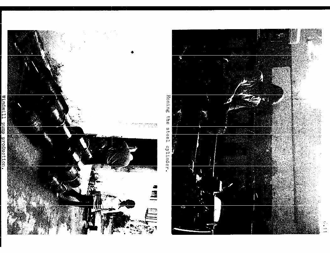
6.2 Preparation of the steel cylinder Preferably the cylinder is made from seamless gas pipe. If not available it is possible to apply "seamedFV - pipe provided that the seam is removed accurately. !l?his is done either by grinding or by means of a simple scraping tool which can be made easily from a piece of suitable metal (hard, e.g.pieceof broken file), which is welded at right angle to the end of the rod. Once shaped by grinding according to the inside cylinder radius, surprisingly good scraping effect is achieved and the removal of the seam is just a matter of a few minutes. The finishing touch is given by some filing and honing.
It will be evident that-causing any unroundness of the cylinder should be avoided during vice-clamping sincethen an inside- nachining on a lathe machine is needed definitely. This might be inconvenient and cause extra complications.
Inside facing of the cylinder by honing is advisable. A simple honing device is made from a cylindrical piece of wood in which three grooves are chiseled at its circumference, 30 that three whet stones have an easy slide in these. A piece of 3/4” gas pipe of approx. one metre length is fitted into the central hole, which has been drilled into the wooden cylinder. TWO
circular sheets are pulled together by three bolts and enclose

6.5
the wooden body and so the whet-stones in longitudinal sense. This set is situated in the centre of the gas-pipe and one of the sheet disks is welded to it to carry the torque. One end of the gas pipe is clamped in the chuck of the lathe machine. The cylinder (to be honed) is slided over the device and the end of the pipe is supported by the tail stock center of the lathe. Hold the cylinder by hand and try to find the most suit- able RPM-number of the lathe for which the whet-stones,as a result of the acting centrifugal forces, serve their purpose best. Move the cylinder to and fro regularly and add some cooling oil from time to time.
Important : See that after completing this procedure the bed and settles of the lathe are cleaned pro- perly from the abrassive grinding particles.
6.3 Footvalve arrangement and pre-machining of the piston
WIO fnrr+ xralvo is rnsdp of a 2 mm steel di=If in which the Y-w _““I -w-w- --- -d--L
large holes in combination with the leather washer allow the w'one-way f'lo~*~ of the water.
The diskchiselledout from the casing flange ;2 will provide the material for the foot valve body. Very accurately the pitch circle (0.6 D) is drawn and the eight hole centres are derived by compass. After accurate center punching the holes are pre- drilled first with a small drill, say 6 mm.

6.6
It is clear that drilling the big holes into this rather thin sheet can be complicated. (Holes become more or less triangu- lar.) However, the same holes should be drilled into the thick wooden block of the piston and at the same pitch. Therefore it is advisable to put the disk on top of the piston block (centred and fixed by means of a 6" bolt) and to drill both the workpieces at once. Do this in a careful manner: see that the tiny ribs in between the holes are not going to crack during the drilling procedure. After this the piston is kept in water again till it is machined to its final shape in a later stage of pump fabrication.(see 6.4.3)
!l!he sharp edges of the holes in the footvalve disk are removed (so that the leather valve will not be damaged in future) and the footvalve disk is positioned and welded to the bottom part of the steel cylinder. See that the nicely honed inside surface of the cylinder is not going to be spoiled due to welding drops and sparks, so cover the inside temporarily or close the valve-
holes. Actually, the cylinder is complete to be built in into
the bottom section of the pump.
6.4.1 The top section
At its bottom part the edge of the casing is made broader in orderto create sufficient surface to press the gasket (if not* the gasket will be cut definitely). It is the best to get the ring 23 made first. Do not weld it yet,but see that it is per- fectly circular and plane. Position it in the casing so that the ring neitherprotrudes nor is sunken down too deep. Check this by rule and give some spot weldings to secure its positi- on.
Stepwise the welding is made now,but very moderately since protruding welding material has to be removed later on (by
filing) in order to achieve a plane gasket flange.
The casing is put on the floor with its bottom facing down- wards. Put the delivery pipe 9 in its centre and slide the 2mm disk 11 over it. Give some spot weldings to connect the

6.7
latter mentioned and take this set out to check the rectangu- larity. Weld the 4 ribs 15 and correct the shape of the sheet iron disk by means of some hammering, Put the arrangement in the casing again and secure it by means of some spot weldings (do not finish the weldings yet). Turn the top section upside down and install the other 4 flats 15 to ensure alignment of delivery pipe in the casing, . Now all the welds are finished air-tight and the top section is ready for the assembly of the pump-rod guide and anchor bolt arra,.nge-
ment which is done in a later stage.
6.4.2 Bottom section
The socket 8 is welded to the disk 11. Then the central bolt 34 and its support flat 17 are composed and welded too. This bottom portion is positioned to the outside casing and secured by means of 8 spot weldings. To be sure to achieve a perfect alignment of bottom casing (so the entire pump) and suction pipe,a pipe is screwed into the socket and the alignment is

6.8
checked and corrected. Then the four outside ribs 15 are posi- tioned and welded and all the weldings are completed.
Put the cylinder into the casing; its bottom is centered by means of the footvalve and its centre bolt. Slide disk 12
over the cylinder and connect them by means of 8 spot wel- dings. Take the set out; position and weld the 4 inside ribs 16 and give some correction by hammering. Then the section is installed again into the casing and connected to it by means of 8 spot weldings first after which final weldings are made stepwise. It will be evident that the air-tight weldings be- tween disk 12 and the outside casing are moderate in orde,? to prevent a great deal of filing there.
6.4.3 !the piston
The wood for the piston (rectangular block) is kept in water for at least one week. This is done in order to allow the wood t 0 rlgrowmr so that the size of the piston, which is given to it by machining, will not increase later resulting in a jamming fit in the steel cylinder. This should be prevented at any price!
Preferably the holes in the pistons are taken over from the footvalve sheet when it is drilled as mentioned earlier.
The block is put on a rod (preferably the pump rod itself) in between two nuts, in order to get it clamped in the chuck of the lathe machine. !Phe outside diameter is turned approx lmm in oversize of the inside diameter of the steel cylinder. Both sides of the piston are faced nicely after which the piston is taken off from the screw rod and final assembling to the pump rod is done. See that the smooth side of the leather washer (piston valve) faces the smoothest plane of the wooden piston. Of course, the burred edges of the steel washers are situated in such way that they do not harm the leather washer a& the wood. Screw the nut and lock it either by means of an extra nut or by applying a locking bolt.

6.9
Final machining to the piston is done now so that it has a nice sliding fit in the steel cylinder.
6.5 Final assembly
First of all the 4 clamping devices and pumprod guide are composed. The piston is slipped into the cylinder and the top section of the pump is situated on the bottom section. See that the outside welds of both the casings are aligned which defines the correct mutual position of Top-and Bottom- section of the pump. Weld the clamping devices to the casing (their position at the circumference are given automatically by the inside joints of the 4 ribs 15 to the bottom portion of the Top section.) Slide the pump rod guide over the pump rod into the pipe
socket which is screwedto the delivery pipe. The presence of the pump rod is essential: now we are sure that the guide is going to be positioned and welded correctly. These welds are made carefully without damaging the screw thread of the socket. The clamping devices are cut open now by hand hacksaw and both the sections as well as the piston are parted and cleaned. In order to prevent corrosion of the pump it is advisable to put some thin tar into the casings, roll them over and over and let the surplus drip out again. Painting of the outside might be ad- visable too (no tar, please!) in order to prolong the life-time of the pump.

6.10
Of course the piston is going to start drying out as long as it is not in its future environment. However, is is advisable to put the assembled piston and leather valve under oil (e.g. ex- pired motor oil) instead of water since the leather should not yet be soaked in water as long as the pump is not installed on the windmill site. (Leather, once soaked in water, becomes brittle and fatigue-sensitive if it has got the opportunity to dry!).
Doing this the oil provides preservation and prevents shrinking
of the pi.-3ton and gives a corrosion protective coating to the cylinder.
The footvalve, piston, gasket and top section are assembled and the 4 bolts are tightened up cross-wise and regularly so that the gasket is compressed nicely and providing a leaka- ge-free connection. Final paint coating is given now.


7.1
7. Installing the windmill
Till so far the following windmill parts are supposed to be prefabricated: tower, headconstruction, moving parts, rotor frame and blades, and the pump section. However, this does not mean that the job has been done. On the contrary: quite a deal of essential steps are to be undertaken yet. First of all the parts are composed partly in order to check the fit. Therefore put the headconstruction on the tower in order to find out whether it rotates smoothly over the tower pipe. Also install the moving parts (mainshaft, crosshead and connecting rod) temporarily and check the functioning. Also check the fit of some blades (at random). Until and unless these checks are confirmed the windmill is ready for transport. One can imagine what inconvenience will be felt on the site if needed corrections should be carried out over there. Another important thing with regard to windmill installation should not be forgotten. Help devices like the jib crane and lifting hook, which are represented in the drawing, are not merely helpful but a must! This from a safety point of view.
The use of the jib crane isreallynecessary for lifting the head construction and rotor both. If this help device is made (see drawing) see that the pulling rope runs nicely in a pulley and cannot run off! The lifting hook is a help device whichprovidesa suitable at- tachment to the head construction which is situated above the point of gravity of the latter. One can imagine what happens if no lifting hook is applied: the head construction tumbles over and nobody will be able to handle it during the procedure of lifting and installing. (See paragraph 7.4).
If all these required precautions have been taken the windmill is ready for transport.
Ihe drawing presents three ways of transport of the windmill in order to reach its destination. See that all the parts are hand-

7.2
led with care and tie them up in order to prevent shifts and mutual movement. It will be evident that for proper transportation some sloth-flags are applied to get the other traffic attended of this remarkable transport.
7.1 Erection of the tower
The holes for the foundation are dug at the desired pitch. Make them of equal depth and wide enough to provide suffi- cient space for the towerleg anchors and to enable the to- wer to shift to a certain extent. The tower is laid in position and a rope is connected to the top portion. Alad- der (or a set ofbamboes)is kept vertically over which the rope is led. Before pulling the tower upright one has to be sure whether the ladder (bamboes) as well as the tower itself cannot fall sidewards. Some extra people can prevent this by guiding and supporting them. After the erection procedure the tower is placed vertically. This is checked by means of a water level gauge which is kept aside the towerpipe ( at top of the towerpipe edge!) Some filling material (e.g. bricks) are wedged under the towerleg angles during the adjustement in vertical sence. Now the desired positimof the centre is checked by means of a rope and plumb-bob, this with regard to the alignment of the tower with the centre of the well or the centre of the tubewell. Again the vertical position is checked and if both positions are satisfactory the towerlegs are
grouted by means of cement and stone- or brick chips.
Unfortunately for this job the application of a simple plumbbob proves to be some- times unreliable due to the
'influence of the wind. How- ever by visual means the centring of the tower can be checked by looking through
eye
help device - with central
hole
the tower pipe along its centre-line.
pump rod guide -
to centre - .-

7.3
!I!he harding-out procedure of the foundation needs at least 5 days,but in the meantime the time-consuming fixation of the pump is carried out. As far as grouting is needed (for pump fixation, washing place etc.) the needed mortar is made available during grouting the towerlegs.
7.2 Installing the headconstruction
NOW the jib crane is going to prove its worth. It is pulled and pushed up aside the tower and finally set on angle 7 of the tower. See that the jib is installed at the "windshadow"- side of the tower, (See drawing) while its two clamping angle- iron arms 4 enclose the tower- pipe in most outward positon.
Now the complete headconstruction without help vane is brought under e2e jib. Ihe lifting hook is bolted to the tail at about I.5 metres distance from the tail hinge. &e head tends to turn towards the tail, since the lock mechanism of the help vane is kept out which makes the entire headconstruction dif- ficult to handle. Arrange a locking device temporarily either by roping the upper tail-beam to the headconstruction or by putting a clamp overthere. Also a pin, stuck through the head and ending up in the upper tail-beaqserves the purpose very well. Lock it
7.4
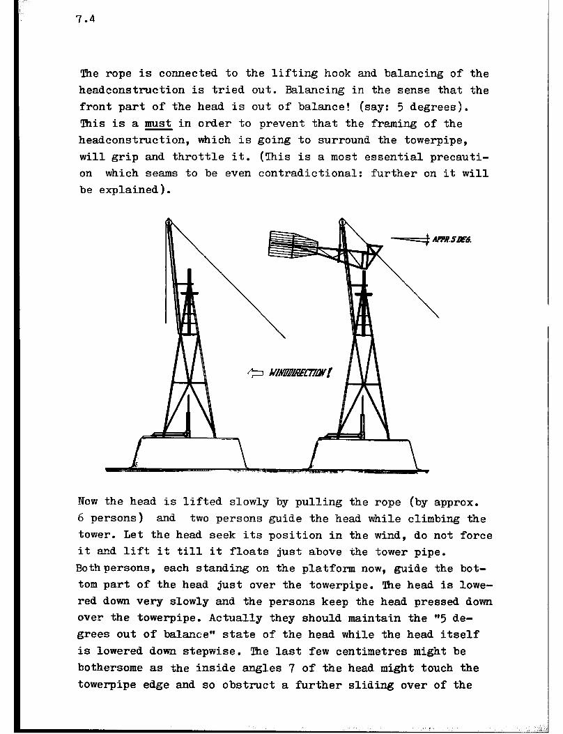
The rope is connected to the lifting hook and balancing of the headconstruction is tried out. Balancing in the sense that the front part of the head is out of balance! (say: 5 degrees). This is a must in order to prevent that the framing of the headconstruction, which is going to surround the towerpipe, will grip and throttle it. (This is a most essential precauti- on which seams to be even contradictional: further on it will be explained).
Now the head is lifted slowly by pulling the rope (by approx. 6 persons) and two persons guide the head while climbing the tower. Let the head seek its position in the wind, do not force it and lift it till it floats just above the tower pipe. Bothpersons, each standing on the platform now, guide the bot- tom part of the head just over the towerpipe. !Ihe head is lowe- red down very slowly and the persons keep the head pressed down over the towerpipe. Actually they should maintain the “5 de- grees out of balancegF state of the head while the head itself is lowered down stepwise. The last few centimetres might be bothersome as the inside angles 7 of the head might touch the towerpipe edge and so obstruct a further sliding over of the

'Ihe rope is lowered down now from the jib crane and it is con- nected to the hub of the rotor frame, but so that the rope pas- ses both the inside - and outside - ring from the back of the rotor! Carefully and slowly the rotor is lifted and two persons guide it while climbing the tower. Extra attention is paid to the extruding shaft which tends to stickinto the lattice of the tower. Finally reaching the level of the platform it is seen that the shaft is positioned on the correct side of the jib crane, since the latter itself will be an obstacle.
7.5
head. If extra attention is paid to a proper centration no problems appear and the head sinks into its final position. Loosen the rope and remove the lifting hook and preparati- ons are undertaken now to install the rotor frame.
7.3 Installing the Rotor
First of all the position of the jib crane should be adjus- ted. Iherefore the jib crane is put in the most upright position. Now the headconstruction is turned 180 degrees so that the front part of the head is touching the jib crane. For security reasons we make a rope connection overthere so that the head on which the rotor, shaft and bearing blocks are going to be bolted, should remain under the pulley of the jib crane. 'Ihis is really necessary as appearing wind might turn the headconstruction suddenly.
The two rotor halves are connected now and the shaft is put into the hub and of course in its original position (the
centre points ! see chapter 5). Ihe hub bolts are tightenedstep- wise as well as securing+ clamping angle irons. Carefully the rotorframe is carried to the tower where it is put in vertical position, standing on one of its six spokes right under the jib crane. Be aware that the extruding shaft points into the lattice of the tower construction and problems will arise during the lifting procedure.

7.6
The entire rotor and shaft are hovering over the head now. With some effort the bearing blocks are positioned above their supports and the rotor is lowered very slowly then. Quickly the bolts are put and nuts are screwed by hand first. The position is secured now and the rope is removed from the rotor and the jib crane is lowered down. Revolve the rotor during some revolutions in order to enable the bearing blocks to set- tle on their supports and tighten the bolts of them finally.
Put the windmill in secured position and bolting of the blades can start. Therefore one person sits on the platform and an- other stands on angle 7 of the tower. Bolts, nuts and the tools can be kept conveniently in a basket which is hung tem- porarily to the platform during this intensive bolting acti- vity. It will be evident that the blades are mounted in cross wise sequence e.g. l-7, 8-2, 3-9, lo-4 etc.
After this the crosshead, assembled with bothconnectionrod and pump rod now, is slided into the towerpipe and the crank bush and central bolt are assembled. See that locking bolt of the P.V.C. - towerpipe insert is removed temporarily in order to allow the crosshead to pass by. Also important is to install the crank bush with its collar facing the crank plane and do not forget to apply the washer in between its bolt head and the bush edge. The crank bolt is tightened up strongljr and of course the locking screw for the P.V.C. - towerpipe insert is re-installed (and should not be forgotten!). Also the wooden pumprodguide is installed on bottom side of the towerpipe and locked with the bolt.
Now the helpvane arrangement is built in and the windmill can be put into the wind enjoying the wind for the first time. .
7.4 Installing the pump
As expressed earlier in chapter 6 the suspension of this very essential part. should not be underrated as many difficulties are felt regarding the alignment and fixation in the well.

7.7
The reciprocating forces, which act on this secticn, can be considerable and of course a minor play in the suspension, either in axial- or in radial sense, will lead to a %oisy dancing and swinging@w performance of the pump. One can imagine what is going to happen then in the long run: play increases to the extent that grouted parts of the suspension come out, bolts and nuts run loose and hammer their way through their counterparts. In short, this is not the way windpower should be utilized and no doubt; such a clumsy performance creates a wrong impression concerning your windmill.
So, better pay a lot of attention to the proper alignment and strong suspension of the pump and delivery pipe in order to prevent the above mentioned malfunctioning.
Though the wells for windmill-sites differ in depth of water table, diameter and structure,at least some prescriptions can be given to obtain suitable suspension:
-In case of centrally situated installation of the windmill above the well it is advisable to apply at least one "bridge construction" which is represented in drawing no. 6. This structure reallyprovides the needed suspension,provided that its legs have been grouted thoroughly in the well casing, Centration at the bottom part of the pump section is obtained either by the tubewell (if applied) or by the application of a similar "bridge construction** which supports the suction pipe to which the pump has been screwed.
In the latter case grouting the bridge into the well casing might be complicated since preferably the bottom part of the pump is situated under the water table in order to make the pump selfpriming and to ensure the desired minimum suction head. !lhis problem is overcome either by grouting the bridge- legs during a period for which the lowest water level exists (dry season, after excessive water removal by another pumping device) or by using an expanding clamp mechanism.

7.8
Provided that the well casing is of proper con- struction the entire pump arrangement can be fixed suitably by means of an expanding clamping device. The latter is composed of 1"gas pipes which are welded at right angle either to the bottom section of the pump or to thesuction pipe. Mutual braces (angle iron) ensure a rigid construc- tion. The clamping arrange- ment is obtained by fitting longthreaded bolts or screw studs into the extruding pipe ends. Tightening their nuts causes the expansion and fixation of the frame. In order to prevent damage to the bricks of the well casing it is necessary to enlarge the bearing surface by means of pieces of angle iron.
Such clamping device proved i.ts worth in combination with the "bridge" construction.
In case of an excentrical position of the windmill no choice is left. Clamps, extended with strong anchors, are grouted in the well casing.

In such cases of pump suspension all forces, acting in vertical sense, should be taken directly by a connect- ion betweenthe pump-section and tower-pipe. !I!his connection is achieved by means of two parallel angle irons of which ends are welded to the halves of the clamps which embrace the tower pipe and delivery pipe.
. . a \ .
7.5Maintena.nce of the windmill
Though the number of moving parts in the windmill are limi- ted yet certain regular check-ups and lubrication services should be undertaken from time to time. Also, in the long run,some moving parts might wear out and are to be replaced then. Fortunately in this design, such parts are cheap in material costs, easy to make and easy to replace. I Due to this the maintenance costs of the windmill are minor and make the application of the windmill attractive.Moreover it is independent of fuel supply. In next paragraph the required maintenance of the windmill is described stepwise.
7.5.1 'Ihe overall structure
Actually corrosion of the steel structure is the greatest enemy of the windmill. If the corrosion problem is tackled in the right way the technical lifetime of the windmill is expected to reach at least 15 years and probably far beyond that figure. !l!herefore it is advisable to have the structure painted tho- roughly by means of at least one primer-coating and two finish coatings (do not forget to chip off the weldingslag). Especially in areas where the air is humid or even: saline (coastal areas) it is advisable to have the best anti-corrosi- ve paint (zinc-based) applied. No doubt, that will be a cost- ly affair but we should realize that it will be paid back in the long run. This is illustrated by the fact that ship- owners are too eager to spend huge amounts of money to get their sea-going vessels protected by means of the rather costly anti-


7.11
- It carries the headconstruction on the edge (this is in axial sense).
- It provides support by its outside to the headconstruc- tion, which encloses it at top- and bottom-part as well. (This in radial sense.)
- Its inside provides the guidance to the crosshead via the contact of the P.V.C.-insert.
No doubt, the “steel to steel" joint of the towerpipe and headconstruction needs some lubrication (grease) from time to time. However as long as the stubborn grease is present no excessive wear is going to occur over there. Also, as long as the P.V.C.-insert remains locked in the tower pipe also the P.V.C.-insert will serve its purpose very persistently,(see 7.5.4)
However,corrosion of the tower as prescribed earlier, has to be taken into account and check-up and remedies should be undertaken,
7.5.3 Headconstruction
Besides its joint to the towerpipe only a few moving parts of this structure need some attention for maintenance. Especial- ly the locks of the security-device should remain free of any play. Ihe functioning of the hinges of the helpvane and tail vane both should be checked from time to time since they might have the tendency either to run loose or to corrode! The first will lead to loose and noisy (so clumsy) joints and the latter lead to a reluctant and hesitating functioning of the mechanism Best remedy is to apply some oil drops there (very moderately) from time to time.
If, unfortunately, the helpvane-lock or the final-lock are worn out better take it out, apply some welding-and reshaping (the

7.12
latter by filling) and get it re-installed properly. There is no need to explain the necessity of a proper functioning storm- security device (see chapter 3).
7.5.4 Moving Parts
It is assumed that the main bearings have been positioned,tig- htened up, and greased and then locked up into their houses. Generally the lubrication is sufficient for millions of revo- lutions and as long as no dust-particles are going to enter this "greasy environment" (in order to form a very destructive grinding paste then) no complications are expected. However one can imagine that in the course of time the grease is 'Volled out" of the bearing and will change its lubrication properties. So, though this is a matter of years, sooner or later new grease should be applied (no oil!) and therefore it will be most con- venient if a greasing-nipple is present at the bearing house. However, if no nipple is there, the bearing house has to be opened now to apply the fresh greasing. In that case be aware that the rotor tends to tumble over if you are going to open the rear bearing house with such disastrous effects as mentioned in chapter 4. Prevent this by roping the rear-end of the mainshaft to angle 2 of the headconstruction.
Generally the nylon (or bronze) bearings of the connecting- rod keep their lubricant very well. Some fresh oil drops from time to time will serve the purpose satisfactorily. The same counts for the wooden cross head and pumprod guides. Properly soaked in oil as they are, they contain the lubricant them- selves and from safety point of view it is the best to keep them in that condition! Generally a**generousfilling up" of the square hole in top of the cross head by means of oil, provides the best guaranteethat these essential wooden parts will maintain their excellent functioning. The appearing play in these parts after some time of functioning might seem to be bother-some, but realize that they have a long way to go before replacement is.really necessary. In short: the wear is accept- able as long as no noisy and clumsy malfunctioning of them oc-

7.13
cur. Then their replacement will be cheap and easy to be car- ried out especially as far as the wooden pumprod guides are concerned. With regard to replacement of the cross head it is advisable to drill completely new holes for the pumprdd/cross- head connection so in the same manner as has been described in chapter 4. It will be evident that in case of replacement of a worn-off cross head the replacement of the P.V.C.-insert is recommended also. Maintain the origional pumprod length.
7.5.5 The Rotor
Besides protection, concerning corrosion, the rotor does not need any maintenance. However in some cases bolts and nuts will run loose due to the alternating character of load on them. A "cracky" noise is the indication for this evil and the best remedy is to check-up all bolt- and nut-connections, es- pecially at the start of the new life of your windmill. In very rare cases some fatigue cracks are going to appear either in the outside blade supports (shearing-fatigue) and/or in the blades somewhere near the outside supports. This is due to poor quality of the sheet iron (mainly its structure) so this is a good reason to apply materials which answer the Stan& ard specifications (for mild steel in this case). If, unfortunately this fatigue occurs, only one remedy exists: get the supports and/or blades replaced by new material and avoid a mispurchase this time. If still doubts remain better go for sheet material which is slightly thicker (1.25 mm for 12 PU 500).
7.5.6 !l!he Piston Pump
Ro doubt, in a good windmill the pump section remains the most bothersome part of it. Besides tne checks of its suspension also checks are to be made with regard to its delivery. Namely, depending on the purity of the lifted water the piston is going to wear sooner or later resulting in a poor delivery which means that it should be replaced then. Replacement just concerns the cheap and simple piston here since the steel cylin- der of the pump-remains the toughest and survives my pistons.

7.14
If this time has come for the change of the piston better re- place the leather valves too. Then guarantee will be there that the newly overhauled pump will serve its purpose for the next period of time without any failure. The span of that time ful- . ly depends on the purity of the water which is pumped from the source. No doubt the presence of sand particles play a signi- ficant role in the life time of the piston and if possible pre- cautions should be undertaken. Iherefore at least, in case of water delivery from a tube well, a proper "washing" procedure is necessary (see chapter 1) otherwise the windmill will do it, with the above mentioned consequence;
7.6 Monitoring of the windmill performance
Though in most of the cases windmills will be put up for their actual purpose (here: water pumping) it might be interesting to yield some data from theirfunctioning For example costbene- fit analysis of it in comparison with those of its VVcompetitors" (diesel pumpset, electric motor pumpsets, waterlifting by bul- locks, or even water lifting by means of human power) may pro- vide information with regard to its feasibility. Of course, this water lifting device depends fully on the wind and will fail it the latter does not supply the required energy. !Phis drawback should be *aken into account before one starts with a wellmesntlarge-scale application of the windmill. Therefore a proper study and monitoring of the "behaviou? of your wind- mill should be undertaken in order to draw right conclusions. W On the other hand the future developments in fuel supply and electrical power supply should be considered as well and cer- tainly net forgotten.
Anyway, collecting data from the windmill is desirable and as far as the technical features of the windmill are concerned the derivation of the delivered water flow versus the occuring windspeedswill be interesting. According to the wind data, valid for the region (see chapter 1) in which the windmill is going to fun&Son, the expected delivery can be estimated.

7.15
No doubt, it will be really interesting and useful to figure out the capacity and prospects of your windmill while knowing that the wind persists blowing even beyond our time.
.

7.16
Chiseling the square hole in the crosshead
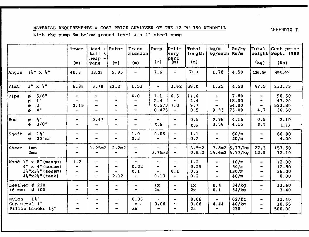
MATERIAL REQUIREMENTS & COST PRICE ANALYSES OF THE 12 PU 350 WINDMILL With the pump 6m below ground level & a 4" steel pump
Alwa?DIX I
*
Total Cost price weight Sept. 1980
(kg) (Rs)
126.56 456.40
Rotor
(ml
Trans mission
Pump t
eli- e=y
Total kg/m ' Rs/kg length kg/each Rs/m
(ml
71.1 1.78 4.50
art (ml (ml r (ml
7.6 -
I
I - I 3.62 38.0 1.25 1 4.50 47.5 1 213.75 1
7.80 18.00 54.00 73.00
1.1 6.5 2.4 - 0.575 7.0 0.475 -
0.6 -
1.0 0.06 - 0.2 - -
2.2m2 - 0.75m2 -
11.6 - 2.4 - 9.7 - 0.5 9.33
90.50 43.20
523.80 4.7 36.50
0.5 2.10 0.4 1.70
0.5 C.96
I I
4.15 0.6 0.56 4.15
66.00 4.00
27.3 157.50 12.5 72.10
12.00 12.50 26.00
8.00
I- I- I- 0.22 0.1 0.1
0.13
10/m SO/m .30/m 40/m
Wood 1" x 8"(nango) 1.2 - 0.25 - 0.2 - 0.2 -
0.06 - \
LX 0.06

Installing a 12 PU 350 head construction
Typical bridge-suspension.

. MATERIAL REQUIREMENTS AND COST PRICE ANALYSES OF THE 12 PU 500 WINDMILL APPEZJDIX Ix With the pump 6 m below ground level and a 6" steel pump (tube well flange6m below ground lev 11 diameter 1,5
Trans- PWP mission steel
PumP
(ml (ml
0.54 - 0.85 - 0.17 -
0.4 4.7 0.9
0.56 0.46
0.77
0.2 - 1.37 0.04
- . ix
0.1 - 0.17
0.3 - lx lx
T Tower Head + Tail & help vane m
Rotor Deli- Total I
W/m ' WW Total very length kg/each Rs/m weight part I (m) I
lost price ept.1980
- Irn) I (no’s) I (ml
41.53 26.00
32.55 18.10 24.30
Angle lb" x lb" Angle l#" x 1s" Angle 2 " x 2 "
41.5 1.78 4 61.2 2.97
1.2 4.47
4.50 73.9 4.50 181.8 4.50 5.4
4.50 0.8 4.50 80 4.50 0.5
7.80/m - 12.30/m 24.3 73.00/m 95.2
105.00/m -
4.15 0.5 4.15 0.8 4.15 1.6
25.00 0.8 90.00 22.3
5.77 97.5 5.77 32.5
10.00 50/m
130.00 - 40.00 - 34.00 - 34.00 -
18.1 13.5 0.48 0.7
7.82 5.28 31.38 0.6 1.25
4.64 50.0 1.50 0.2 2.40
3.60 60.00
2.25
Flat 1" x k" Flat I\" x &" Flat 1%" x 3/8"
0.4 6.5 12.1 7.0 10.2
0.5
2.01 9.33
0.8 0.56 0.74 0.8 0.96
1 0.7 2.22
2.65
3.10 48.80 44.60 52.50
Pipe 518" Pipe 3/4" Pipe 4" Pipe 6 m
Rod 3/8" Rod #" Rod 4"
lx 4x 1/3x
2.10 3.30 6.60
I Shaft 1" ,Shaft 2" 1 I 0.2
1.41 3.95
15.8 5.00
26.90
Sheet Imm-1 x 2.5m Sheet 2mm 1 x 2.5m
68.60 87.50
14.00 10.00 26.00 12.00 13.60
6.80
Wood 1" x 12" (mango) ~\Jc)od 5" x 5" (sesam) Wood 3" x 7" (teak) Wood 45"X 45" (sesam) Leather 4 29 cm
6m1n 6 15cm
1.4

(12 PU 350)
I PVC pipe 3" 1 - - 1 .- 1 0.55 - 1 23/m 1 - 1 12.65
MS T - socket 3" MS Socket 3" MS Flange 3' MS Flange 4"
lx - lx 30 30.00 lx lx 2x a - 16.00 lx - lx 24 - 24.00 2x - 2x 34 - 68.00
Primer 2L 20/L - 40.00 Thinner 2L 21.50/L - 43.00 Paint 4L - 35/L - 140.00
Bolts/nuts/Washers/ Spring/Washers/Springs - - - - 13/kg 10 130.00
Welding rods 100.00 . . . . . . . ,
TOTAL 2987.36 -------- --B-m---

PVC pipe 4"
MS Steel socket 4" MS Steel T socket 4"
Primer Thinner Paint
Bolts/nuts/washer/ springs v*-a~*-3/8"- - tj " 0 %', - 7/0"
I Welding Rods
c -._ -.
i 0.04
--.
0.08 - 62.00 - 16.50 0.04 1Okg 40.00 0.4 16.00
2x - 365/each - 730.00
0.7 - 32.75/m - 23.00
2x - 14/each - lx - SO/each -
4L - 20.00/L - 4L - 21.50/L - 8L - 35.00/L -
13.00/kg 12 I I I 1 13.00/kg 12
28.00 50.00
80.00 86.00
280.00
156.00
TOTAL 5137.70 ------- ---__--