Embed Size (px)
Citation preview

Microfluidics as a functional tool for cell mechanicsSiva A. Vanapalli, Michel H. G. Duits, and Frieder Mugele Citation: Biomicrofluidics 3, 012006 (2009); doi: 10.1063/1.3067820 View online: http://dx.doi.org/10.1063/1.3067820 View Table of Contents: http://bmf.aip.org/resource/1/BIOMGB/v3/i1 Published by the AIP Publishing LLC. Additional information on BiomicrofluidicsJournal Homepage: http://bmf.aip.org/ Journal Information: http://bmf.aip.org/about/about_the_journal Top downloads: http://bmf.aip.org/features/most_downloaded Information for Authors: http://bmf.aip.org/authors
Downloaded 23 Aug 2013 to 35.8.11.2. This article is copyrighted as indicated in the abstract. Reuse of AIP content is subject to the terms at: http://bmf.aip.org/about/rights_and_permissions
Microfluidics as a functional tool for cell mechanicsSiva A. Vanapalli,1,a� Michel H. G. Duits,2 and Frieder Mugele2
1Department of Chemical Engineering, Texas Tech University, Lubbock, Texas 79409, USA2Physics of Complex Fluids, Department of Science & Technology and MESA�Institute of Nanotechnology, University of Twente, P.O. Box 217, 7500 AE Enschede,The Netherlands
�Received 9 December 2008; accepted 15 December 2008; published online 5 January 2009�
Living cells are a fascinating demonstration of nature’s most intricate and well-coordinated micromechanical objects. They crawl, spread, contract, and relax—thus performing a multitude of complex mechanical functions. Alternatively, theyalso respond to physical and chemical cues that lead to remodeling of the cyto-skeleton. To understand this intricate coupling between mechanical properties, me-chanical function and force-induced biochemical signaling requires tools that arecapable of both controlling and manipulating the cell microenvironment and mea-suring the resulting mechanical response. In this review, the power of microfluidicsas a functional tool for research in cell mechanics is highlighted. In particular,current literature is discussed to show that microfluidics powered by soft litho-graphic techniques offers the following capabilities that are of significance forunderstanding the mechanical behavior of cells: �i� Microfluidics enables the cre-ation of in vitro models of physiological environments in which cell mechanics canbe probed. �ii� Microfluidics is an excellent means to deliver physical cues thataffect cell mechanics, such as cell shape, fluid flow, substrate topography, andstiffness. �iii� Microfluidics can also expose cells to chemical cues, such as growthfactors and drugs, which alter their mechanical behavior. Moreover, these chemicalcues can be delivered either at the whole cell or subcellular level. �iv� Microfluidicdevices offer the possibility of measuring the intrinsic mechanical properties ofcells in a high throughput fashion. �v� Finally, microfluidic methods provide ex-quisite control over drop size, generation, and manipulation. As a result, dropletsare being increasingly used to control the physicochemical environment of cellsand as biomimetic analogs of living cells. These powerful attributes of microfluid-ics should further stimulate novel means of investigating the link between physi-cochemical cues and the biomechanical response of cells. Insights from such stud-ies will have implications in areas such as drug delivery, medicine, tissueengineering, and biomedical diagnostics. © 2009 American Institute of Physics.�DOI: 10.1063/1.3067820�
I. INTRODUCTION
Mechanical processes like pushing, pulling, and squeezing play a remarkably significant rolein the biological function of a cell.1,2 For example, such forces turn out to affect biologicalprocesses such as cell growth, division, migration, and death. In addition, mechanical forces at thecellular level impact the function of biological structures ranging from large length scales such astissues to small length scales such as genes. As a result it is not surprising that when living cellsare affected by disease, changes in their mechanical properties also occur. Indeed cell mechanicshas been implicated in a variety of diseases, such as cancer,3–5 malaria,6 sickle cell anemia,7
asthma, and glaucoma.8 For example, Cross et al.5 studied individual cells taken from the tissues
a�Electronic mail: [email protected].
BIOMICROFLUIDICS 3, 012006 �2009�
3, 012006-11932-1058/2009/3�1�/012006/15/$25.00 © 2009 American Institute of Physics
Downloaded 23 Aug 2013 to 35.8.11.2. This article is copyrighted as indicated in the abstract. Reuse of AIP content is subject to the terms at: http://bmf.aip.org/about/rights_and_permissions
of suspected patients with various cancers. From physiology it is suggested that metastatic cancercells must be more deformable than healthy cells, to be able to invade tissue. Consistent with thisnotion, individual metastatic cancer cells were indeed found to have lower Young’s moduli mea-sured via atomic force microscope. Also, in suspended state, cancerous and metastatic cells couldbe distinguished from healthy breast epithelial cells via their resistance to optical stretching.9 Thusthere exists an intimate link between the mechanical properties and the diseased state of livingcells.
From a mechanics perspective it is well known that intracellular forces are generated andsupported via an intracellular framework called the cytoskeleton. This network, containing actinfilaments, microtubules, and intermediate filaments, is dynamic in nature, and is regulated viapolymerization and depolymerization rates, which in turn are controlled via molecular motors andATP.10 This coupling between intracellular mechanics and chemistry appears to be universal.11,12 Itallows cells to respond mechanically to external stresses by activating biochemical signalingcascades and also underlies the possibility to restore the mechanical properties of diseased cells bypharmacological interventions. Thus cellular mechanotransduction studies that involve under-standing and the control of interactions between mechanical forces and biochemical signalingpathways could lead to novel therapeutic strategies to treat diseases.
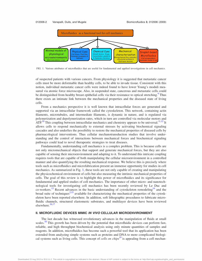
Fundamentally, understanding cell mechanics is a complex problem. This is because cells arenot only micromechanical objects that support and generate mechanical forces, but they are alsocapable of sensing their microenvironment and adapting to it. To understand this intricate couplingrequires tools that are capable of both manipulating the cellular microenvironment in a controlledmanner and also quantifying the resulting mechanical response. We believe this is precisely wheretools such as microfluidics and microfabrication present an immense opportunity for studies in cellmechanics. As summarized in Fig. 1, these tools are not only capable of creating and manipulatingthe physicochemical environment of cells but also measuring the intrinsic mechanical properties ofcells. The goal of this review is to highlight this power of microfluidics and its significance forfundamental and applied studies of cell mechanics. The importance of other micro- and nanotech-nological tools for investigating cell mechanics has been recently reviewed by Le Duc andco-workers.13 Recent advances in the basic understanding of cytoskeleton remodeling14 and thebroad suite of techniques2,15 available for characterizing the mechanical properties of the cytosk-eleton have been reported elsewhere. In addition, soft lithographic procedures to fabricate micro-fluidic channels, structured elastomeric substrates, and multilayer devices have been reviewedelsewhere.16,17
II. MICROFLUIDIC DEVICES MIMIC IN VIVO CELLULAR MICROENVIRONMENT
The last decade has witnessed revolutionary advances in the manipulation of fluids at smallscales.18 This growth has been driven by the potential that microfluidic devices can perform fast,reliable, and high throughput biochemical analysis using only minute quantities of samples andreagents. In addition, microfluidics has become such a powerful tool that its application has beenextended from analyzing simple systems such as proteins and DNA to more complicated biologi-cal systems such as living cells. This concept of cells on chips19 is appealing from a cell mechan-
Microfluidics as a functional tool for cell mechanics
Mechanicalcharacterization
(Biomechanical flow cytometry,μStructured surfaces &Multi-layer devices)
Minimal models ofphysiological
microenvironments(Microvasculature, Lung)
Physical Cues(Cell shape, Fluid flow,Substrate topography &
Stiffness)
Chemical Cues(Growth factors, Drugs,Concentration gradients& Substrate chemistry)
Droplet-basedMicrofluidics(Cell encapsulation,
Biomimetic model of cell)
FIG. 1. Various attributes of microfluidics that are useful for fundamental and applied investigations in cell mechanics.
012006-2 Vanapalli, Duits, and Mugele Biomicrofluidics 3, 012006 �2009�
Downloaded 23 Aug 2013 to 35.8.11.2. This article is copyrighted as indicated in the abstract. Reuse of AIP content is subject to the terms at: http://bmf.aip.org/about/rights_and_permissions
ics point of view, because microfluidic systems can be built that mimic the in vivo environment ofcells, allowing mechanical behavior of cells to be studied under almost physiological conditions,with minimal consumption of reagents.
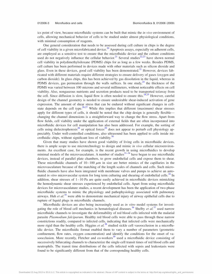
One general consideration that needs to be assessed during cell culture in chips is the degreeof cell viability in a given microfabricated device.20 Apoptosis assays, especially on adherent cells,are employed as a sensitive test to ensure that the microfluidic device and the culture conditionsused do not negatively influence the cellular behavior.21 Several studies22,23 have shown normalcell viability in polydimethylsiloxane �PDMS� chips for as long as a few weeks. Besides PDMS,cell culture has been performed in devices made with other materials such as silicon dioxide andglass. Even in these devices, good cell viability has been demonstrated.21 However, devices fab-ricated with different materials require different strategies to ensure delivery of gases �oxygen andcarbon dioxide�. In glass chips, this has been achieved by gas dissolution in the liquid, whereas inPDMS devices, gas permeation through the walls suffices. In one study,24 the thickness of thePDMS was varied between 100 microns and several millimeters, without noticeable effects on cellviability. Also, nongaseous nutrients and secretion products need to be transported to/away fromthe cell. Since diffusion is slow, liquid flow is often needed to ensure this.24,25 However, carefuldesign of the channel geometry is needed to ensure undesirable shear-induced activation of geneexpression. The amount of shear stress that can be endured without significant changes in cell-state depends on the cell type.26,27 While this implies that different �maximum� shear stressesapply for different types of cells, it should be noted that the chip design is generally flexible—changing the channel dimensions is a straightforward way to change the flow stress. Apart fromflow fields, cell viability under the application of external fields that are often incorporated intomicrofluidic devices for cell manipulation has also been addressed. For example, the sorting ofcells using dielectrophoresis28 or optical forces29 does not appear to perturb cell physiology ap-preciably. Under well-controlled conditions, also ultrasound has been applied to cells inside mi-crofluidic chips, without significant loss of viability.30
Given that many studies have shown good viability of living cells in microfluidic devices,there is ample scope to use microtechnology to design and mimic in vivo cellular microenviron-ments. An excellent case, for example, is the recent growth in using microfluidics to developminimal models of the microvasculature. A number of studies31–34 have begun to use microfluidicdevices, instead of parallel plate chambers, to grow endothelial cells and expose them to shear.These microfluidic channels of 10–100 �m in size are better mimics of the capillaries in themicrovasculature because of the matching of the length scales of channels and cells. Such micro-fluidic channels have also been integrated with membrane valves and pumps to achieve an auto-mated in vitro microvascular system for long term culturing and shearing of endothelial cells.34 Inaddition, shear stresses of 1–10 Pa are quite easily achieved in microfluidic devices mimickingthe hemodynamic shear stresses experienced by endothelial cells. Apart from using microfluidicdevices for microvasculature studies, a recent development has been the application of two-phasemicrofluidic systems to mimic the physiology and pathophysiology associated with pulmonaryairways. Huh et al.35 were able to demonstrate mechanical injury of airway epithelial cells due torupture of liquid plugs in microfluidic channels.
Microfluidic devices are also being increasingly used as in vitro model systems for investi-gating the role of blood cell mechanics in hematological diseases.36 Shelby et al.37 used narrowmicrofluidic channels to investigate the deformability of red blood cells infected with the malarialparasite Plasmodium falciparum. Healthy red blood cells were able to pass through these narrowconstrictions readily, compared to infected cells, indicating that infected cells were mechanicallymore rigid than the healthy cells. Higgins et al.38 studied sickle cell vasoocclusion in a microflu-idic device. The microfluidic format enabled them to vary a number of parameters �geometricconfinement, flow rates, oxygen concentration� and identify the conditions for the onset of va-soocclusion. More recently, Fletcher and co-workers39 used a microfluidic device consisting ofsuccessively bifurcating channels to characterize the single-cell transit times of red blood cells andneutrophils. The transit time distributions of the cells infected with sepsis and leukostasis werefound to be significantly different from that of the corresponding healthy cells.
012006-3 Microfluidics and cells Biomicrofluidics 3, 012006 �2009�
Downloaded 23 Aug 2013 to 35.8.11.2. This article is copyrighted as indicated in the abstract. Reuse of AIP content is subject to the terms at: http://bmf.aip.org/about/rights_and_permissions
III. MICROFLUIDICS AS A MEANS TO DELIVER PHYSICAL CUES TO CELLS
Microfluidics and microfabrication are versatile means of manipulating physical cues thataffect cell mechanical behavior such as fluid flow, substrate topography and stiffness, and cellshape. For example, cells can be easily exposed to laminar shear and extentional flows in micro-fluidic devices.40 More complex flows including pulsatile17,41 and chaotic flows42,43 can also begenerated in microfluidic devices. The capability of producing such a broad range of flow types inmicrochannels opens up new possibilities for studying flow-induced cytoskeleton remodeling,11
particularly for cells that are sensitive to fluid forces such as endothelial cells.Soft lithographic techniques allow varying the topography of substrate with feature size rang-
ing from microns to nanometers.44 Remarkably, cells can sense substrate topography as well asstiffness.45,46 A recent study has shown that the elastic modulus of cells grown on softer substratesis lower than those grown on harder substrates and that cells tend to tune their stiffness to thestiffness of the substrate.47 Cancer cells have also been identified via their growth on soft agargels.4 In certain stem cells it has been demonstrated that their development into highly specializedcells can be steered via the stiffness of the substrate.48 As a result, microfluidic devices should findincreasing application in such studies, as the substrate stiffness of these devices can be easilytuned. For example, the stiffness of substrates fabricated using soft lithography can be varied from�1 kPa to 100 kPa.45,49 Microfluidic strategies also allow cells to be grown in 3D microstructuresthat could be used to study anchorage dependent cells.33,50,51
Apart from the use of microfluidics to control the physical microenvironment of the cell, italso allows control over the shape of individual cells. Patterning techniques such as microcontactprinting52 are well equipped to control the shape of single cells, including introducing anisotropyin shape. The basic principle exploits the affinity of adherent cells to regions where the extracel-lular matrix is present. Although patterning techniques work well for cells on open substrates,coupling them to microfluidic channels requires additional steps including cumbersome alignment.The advantage of coupling microfluidic networks and patterning techniques is that the channelsprovide a conduit for delivery of either physical or chemical cues in a precise manner. Suchfunctionality could be useful in endothelial cell mechanics to address the link between cell mor-phology and flow-induced cytoskeleton remodeling. In this regard, we recently developed a multi-layer device that has the capability to pattern cells inside microchannels53 �see Fig. 2�. Thesedevices were fabricated in a manner similar to membrane valves, except that topographical struc-tures were introduced on the roof of the fluid channel. The working principle of this device isbased on using the deformation of the structured elastomeric membrane �SEM� to mask a certainarea on the microchannel surface and passivate the unmasked area with a blocking agent. Subse-quently extracellular matrix proteins can be introduced that preferentially adsorb in the previouslyprotected area. Thus, depending on the shape of the feature on the SEM, adhesive islands ofvarious shapes can be obtained. Figure 3 shows that this technique can indeed provide goodcontrol over the shape of a cell on a microchannel surface.
IV. MICROFLUIDICS AS A MEANS TO EXPOSE CELLS TO CHEMICAL CUES
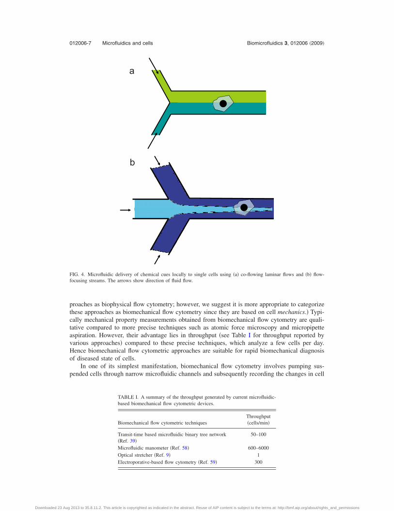
Microfluidics is capable of delivering chemical cues such as growth factors and drugs to livingcells that in turn affect their mechanical behavior. The laminar nature of microfluidic flows pro-vides unique possibilities for stimulating cells chemically. Coflowing streams can be used todeliver chemical cues locally to individual cells �see Fig. 4�a��. Takayama et al.54 were the first toapply this principle and demonstrate selective labeling of mitochondria with different fluorescentdyes in endothelial cells. The laminar interface in such flows can also be controlled with a highdegree of spatiotemoral resolution.55 Local chemical stimuli have also been delivered using mi-crofluidic flow-focusing as shown in Fig. 4�b�.56 Gradients in concentration of chemical cuesincluding extracellular matrix proteins on a substrate can also be easily set up using microfluidiclaminar flows. Motivated by studies on chemotaxis, several groups have reported a variety ofmicrofluidic networks that are capable of generating simple to complex chemical gradients.57
012006-4 Vanapalli, Duits, and Mugele Biomicrofluidics 3, 012006 �2009�
Downloaded 23 Aug 2013 to 35.8.11.2. This article is copyrighted as indicated in the abstract. Reuse of AIP content is subject to the terms at: http://bmf.aip.org/about/rights_and_permissions
V. MICROFLUIDIC TOOLS TO CHARACTERIZE THE MECHANICAL PROPERTIES OFCELLS
So far we have discussed how microfluidics allows regulating the physicochemical environ-ment of cells. We now discuss microfluidic strategies that have been developed to characterizecellular mechanical properties. In particular, biomechanical flow cytometry is well suited foranalyzing suspended cells and microstructured elastomeric surfaces and multi-layer devices aresuitable for characterizing the mechanical behavior of adherent cells. Below we discuss these toolsin detail.
Biomechanical flow cytometry: Recently, several groups9,39,58–60 have demonstrated microflu-idic strategies to screen suspended cells mechanically in microchannels. Akin to conventional flowcytometry where cells are selectively detected based on fluorescence, these recent methods detectcells mechanically in microfluidic devices by exploiting characteristics that are linked to theirindividual mechanical properties. Such approaches therefore fall under the category of biome-chanical flow cytometry. �Recently Fletcher and co-workers collectively referred to these ap-
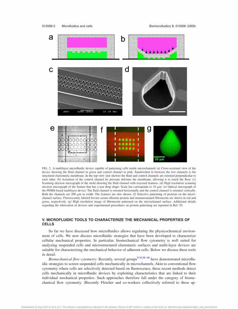
FIG. 2. A multilayer microfluidic device capable of patterning cells inside microchannels �a� Cross-sectional view of thedevice showing the fluid channel in green and control channel in pink. Sandwiched in between the two channels is thestructured elastomeric membrane. In the top view �not shown� the fluid and control channels are oriented perpendicular toeach other. �b� Actuation of the control channel by pressure deforms the membrane, allowing it to touch the floor. �c�Scanning electron micrograph of the mold showing the fluid channel with recessed features. �d� High resolution scanningelectron micrograph of the feature that has a tear drop shape. Scale bar corresponds to 10 �m. �e� Optical micrograph ofthe PDMS-based multilayer device. The fluid channel is oriented horizontally and the control channel is oriented vertically.Both the channels are 200 �m in width. The features are also shown. �f� Selective patterning of proteins on the micro-channel surface. Fluorescently labeled bovine serum albumin protein and immunostained fibronectin are shown in red andgreen, respectively. �g� High resolution image of fibronectin patterned on the microchannel surface. Additional detailsregarding the fabrication of devices and experimental procedures on protein patterning are reported in Ref. 53.
012006-5 Microfluidics and cells Biomicrofluidics 3, 012006 �2009�
Downloaded 23 Aug 2013 to 35.8.11.2. This article is copyrighted as indicated in the abstract. Reuse of AIP content is subject to the terms at: http://bmf.aip.org/about/rights_and_permissions
a
b
c
d
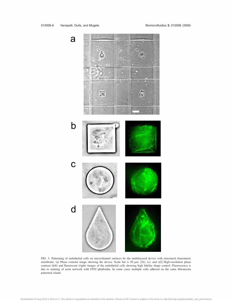
FIG. 3. Patterning of endothelial cells on microchannel surfaces by the multilayered device with structured elastomericmembrane. �a� Phase contrast image showing the device. Scale bar is 50 �m. ��b�, �c�, and �d�� High-resolution phasecontrast �left� and fluorescent �right� images of the endothelial cells showing high fidelity shape control. Fluorescence isdue to staining of actin network with FITC-phalloidin. In some cases multiple cells adhered on the same fibronectinpatterned island.
012006-6 Vanapalli, Duits, and Mugele Biomicrofluidics 3, 012006 �2009�
Downloaded 23 Aug 2013 to 35.8.11.2. This article is copyrighted as indicated in the abstract. Reuse of AIP content is subject to the terms at: http://bmf.aip.org/about/rights_and_permissions
proaches as biophysical flow cytometry; however, we suggest it is more appropriate to categorizethese approaches as biomechanical flow cytometry since they are based on cell mechanics.� Typi-cally mechanical property measurements obtained from biomechanical flow cytometry are quali-tative compared to more precise techniques such as atomic force microscopy and micropipetteaspiration. However, their advantage lies in throughput �see Table I for throughput reported byvarious approaches� compared to these precise techniques, which analyze a few cells per day.Hence biomechanical flow cytometric approaches are suitable for rapid biomechanical diagnosisof diseased state of cells.
In one of its simplest manifestation, biomechanical flow cytometry involves pumping sus-pended cells through narrow microfluidic channels and subsequently recording the changes in cell
a
b
FIG. 4. Microfluidic delivery of chemical cues locally to single cells using �a� co-flowing laminar flows and �b� flow-focusing streams. The arrows show direction of fluid flow.
TABLE I. A summary of the throughput generated by current microfluidic-based biomechanical flow cytometric devices.
Biomechanical flow cytometric techniquesThroughput�cells/min�
Transit-time based microfluidic binary tree network�Ref. 39�
50–100
Microfluidic manometer �Ref. 58� 600–6000Optical stretcher �Ref. 9� 1Electroporative-based flow cytometry �Ref. 59� 300
012006-7 Microfluidics and cells Biomicrofluidics 3, 012006 �2009�
Downloaded 23 Aug 2013 to 35.8.11.2. This article is copyrighted as indicated in the abstract. Reuse of AIP content is subject to the terms at: http://bmf.aip.org/about/rights_and_permissions
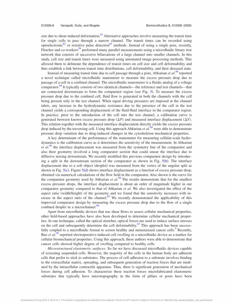
size due to shear-induced deformation.61 Alternative approaches involve measuring the transit timefor single cells to pass through a narrow channel. The transit times can be recorded usingoptoelectronic62 or resistive pulse detection63 methods. Instead of using a single pore, recently,Fletcher and co-workers39 performed many parallel measurements using a microfluidic binary treenetwork that consists of successive bifurcations of a large channel into smaller channels. In thisstudy, cell size and transit times were measured using automated image processing methods. Thisallowed them to delineate the dependence of transit times on cell size and cell deformability andthus establish a link between transit time distributions, cell deformability, and their diseased state.
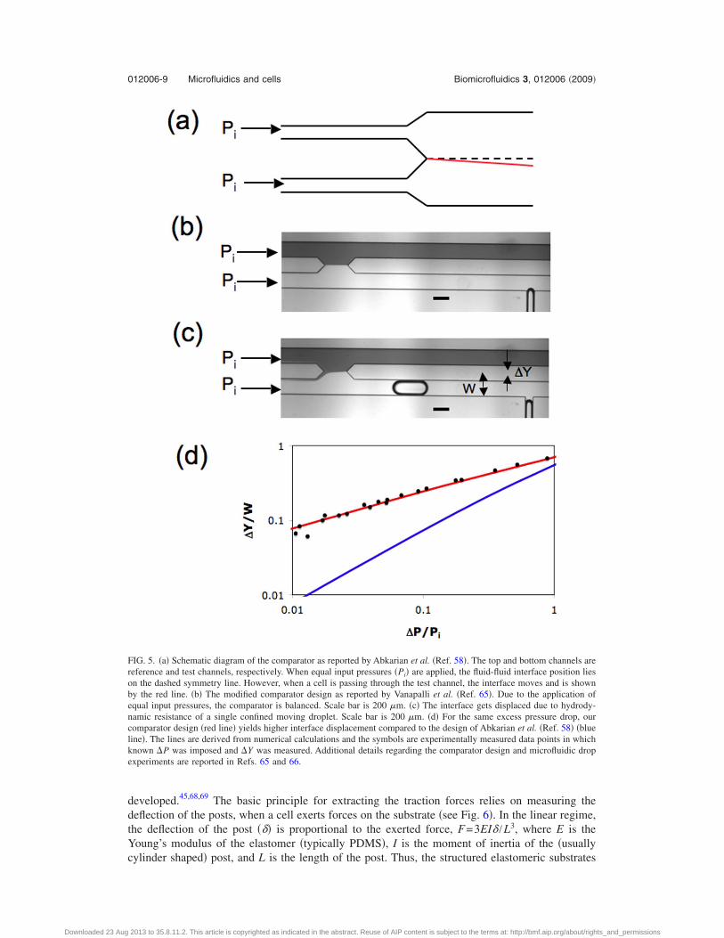
Instead of measuring transit time due to cell passage through a pore, Abkarian et al.58 reporteda novel technique called microfluidic manometer to measure the excess pressure drop due topassage of a cell in a confined channel. The microfluidic manometer is a fluidic analog of a voltagecomparator.64 It typically consists of two identical channels—the reference and test channels—thatare connected downstream to form the comparator region �see Fig. 5�. To measure the excesspressure drop due to the confined cell, fluid flow is generated in both the channels with the cellbeing present only in the test channel. When equal driving pressures are imposed at the channelinlets, any increase in the hydrodynamic resistance due to the presence of the cell in the testchannel yields a corresponding displacement of the fluid-fluid interface in the comparator region.In practice, prior to the introduction of the cell into the test channel, a calibration curve isgenerated between known excess pressure drop ��P� and measured interface displacement ��Y�.This relation together with the measured interface displacement directly yields the excess pressuredrop induced by the traversing cell. Using this approach Abkarian et al.58 were able to demonstratepressure drop variation due to drug-induced changes in the cytoskeleton mechanical properties.
A key determinant of the performance of the manometer for measuring cellular-scale hydro-dynamics is the calibration curve as it determines the sensitivity of the measurement. In Abkarianet al.58 the interface displacement was measured from the symmetry line of the comparator andalso their geometry involved a long comparator section that could smear the interface due todiffusive mixing downstream. We recently modified this previous comparator design by introduc-ing a split in the downstream section of the comparator as shown in Fig. 5�b�. The interfacedisplacement due to a soft object �droplet� was measured from the vertex of the angular split asshown in Fig. 5�c�. Figure 5�d� shows interface displacement as a function of excess pressure drop,obtained via numerical calculations of the flow field in the comparator. Also shown is the curve forthe comparator geometry used by Abkarian et al.58 The results demonstrate that for the smallestexcess pressure drops, the interface displacement is about an order of magnitude higher in ourcomparator geometry compared to that of Abkarian et al. We also investigated the effect of theaspect ratio �width/height� of the geometry and we found that the sensitivity increases with in-crease in the aspect ratio of the channel.65 We recently demonstrated the applicability of thisimproved comparator design by measuring the excess pressure drop due to the flow of a singleconfined droplet in a microchannel.66
Apart from microfluidic devices that use shear flows to assess cellular mechanical properties,other field-based approaches have also been developed to determine cellular mechanical proper-ties. In one technique, called the optical stretcher, optical forces are used to induce surface stresseson the cell and subsequently determine the cell deformability.67 This approach has been success-fully coupled to a microfluidic format to screen healthy and metastasized cancer cells.9 Recently,Bao et al.59 reported electroporative-induced cell swelling in a microfluidic device as a marker forcellular biomechanical properties. Using this approach, these authors were able to demonstrate thatcancer cells showed higher degree of swelling compared to healthy cells.
Microstructured elastomeric surfaces: So far we have discussed microfluidic devices capableof screening suspended cells. However, the majority of the cells in the human body are adherentcells that prefer to stick to substrates. The process of cell adhesion to a substrate involves bindingto the extracellular matrix, spreading, and subsequent generation of traction forces that are medi-ated by the intracellular contractile apparatus. Thus, there is significant generation of mechanicalforces during cell adhesion. To characterize these traction forces microfabricated elastomericsubstrates that typically have microtopography in the form of pillars or posts have been
012006-8 Vanapalli, Duits, and Mugele Biomicrofluidics 3, 012006 �2009�
Downloaded 23 Aug 2013 to 35.8.11.2. This article is copyrighted as indicated in the abstract. Reuse of AIP content is subject to the terms at: http://bmf.aip.org/about/rights_and_permissions
developed.45,68,69 The basic principle for extracting the traction forces relies on measuring thedeflection of the posts, when a cell exerts forces on the substrate �see Fig. 6�. In the linear regime,the deflection of the post ��� is proportional to the exerted force, F=3EI� /L3, where E is theYoung’s modulus of the elastomer �typically PDMS�, I is the moment of inertia of the �usuallycylinder shaped� post, and L is the length of the post. Thus, the structured elastomeric substrates
FIG. 5. �a� Schematic diagram of the comparator as reported by Abkarian et al. �Ref. 58�. The top and bottom channels arereference and test channels, respectively. When equal input pressures �Pi� are applied, the fluid-fluid interface position lieson the dashed symmetry line. However, when a cell is passing through the test channel, the interface moves and is shownby the red line. �b� The modified comparator design as reported by Vanapalli et al. �Ref. 65�. Due to the application ofequal input pressures, the comparator is balanced. Scale bar is 200 �m. �c� The interface gets displaced due to hydrody-namic resistance of a single confined moving droplet. Scale bar is 200 �m. �d� For the same excess pressure drop, ourcomparator design �red line� yields higher interface displacement compared to the design of Abkarian et al. �Ref. 58� �blueline�. The lines are derived from numerical calculations and the symbols are experimentally measured data points in whichknown �P was imposed and �Y was measured. Additional details regarding the comparator design and microfluidic dropexperiments are reported in Refs. 65 and 66.
012006-9 Microfluidics and cells Biomicrofluidics 3, 012006 �2009�
Downloaded 23 Aug 2013 to 35.8.11.2. This article is copyrighted as indicated in the abstract. Reuse of AIP content is subject to the terms at: http://bmf.aip.org/about/rights_and_permissions
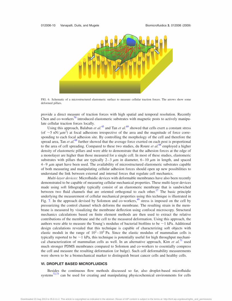
provide a direct measure of traction forces with high spatial and temporal resolution. RecentlyChen and co-workers70 introduced elastomeric substrates with magnetic posts to actively manipu-late cellular traction forces locally.
Using this approach, Balaban et al.45 and Tan et al.69 showed that cells exert a constant stress�of �5 nN /�m2� at focal adhesions irrespective of the area and the magnitude of force corre-sponding to each focal adhesion site. By controlling the morphology of the cell and therefore thespread area, Tan et al.69 further showed that the average force exerted on each post is proportionalto the area of cell spreading. Compared to these two studies, du Roure et al.68 employed a higherdensity of elastomeric pillars and were able to demonstrate that the adhesion forces at the edge ofa monolayer are higher than those measured for a single cell. In most of these studies, elastomericsubstrates with pillars that are typically 2–3 �m in diameter, 6–10 �m in length, and spaced4–9 �m apart have been used. The availability of microstructured elastomeric substrates capableof both measuring and manipulating cellular adhesion forces should open up new possibilities tounderstand the link between external and internal forces that regulate cell mechanics.
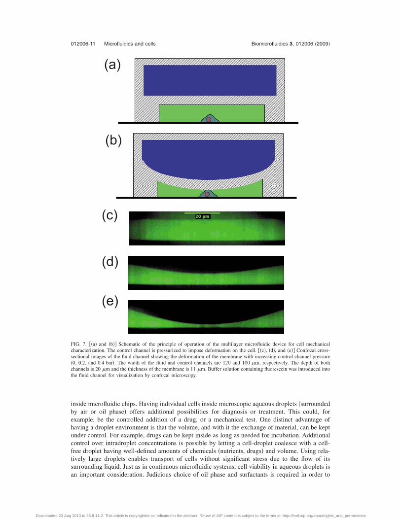
Multi-layer devices: Microfluidic devices with deformable membranes have also been recentlydemonstrated to be capable of measuring cellular mechanical properties. These multi-layer devicesmade using soft lithography typically consist of an elastomeric membrane that is sandwichedbetween two fluid channels that are oriented orthogonal to each other.17 The basic principleunderlying the measurement of cellular mechanical properties using this technique is illustrated inFig. 7. In the approach devised by Solomon and co-workers,49 stress is imposed on the cell bypressurizing the control channel which deforms the membrane. The resulting strain in the mem-brane is measured by visualizing the membrane deflection using confocal microscopy. Structuralmechanics calculations based on finite element methods are then used to extract the relativecontributions of the membrane and the cell to the measured deformation. Using this approach, theauthors were able to measure the Young’s modulus of bacterial biofilms to be �1 kPa. Additionaldesign calculations revealed that this technique is capable of characterizing soft objects withelastic moduli in the range of 102–105 Pa. Since the elastic modulus of mammalian cells istypically reported to be �1 kPa, this technique is potentially useful for high throughput mechani-cal characterization of mammalian cells as well. In an alternative approach, Kim et al.71 usedmuch stronger PDMS membranes compared to Solomon and co-workers to essentially compressthe cell and measure the resulting deformation �or bulge�. Such cell deformability measurementswere shown to be a biomechanical marker to distinguish breast cancer cells and healthy cells.
VI. DROPLET BASED MICROFLUIDICS
Besides the continuous flow methods discussed so far, also droplet-based microfluidicsystems72,73 can be used for creating and manipulating physicochemical environments for cells
FIG. 6. Schematic of a microstructured elastomeric surface to measure cellular traction forces. The arrows show somedeformed pillars.
012006-10 Vanapalli, Duits, and Mugele Biomicrofluidics 3, 012006 �2009�
Downloaded 23 Aug 2013 to 35.8.11.2. This article is copyrighted as indicated in the abstract. Reuse of AIP content is subject to the terms at: http://bmf.aip.org/about/rights_and_permissions
inside microfluidic chips. Having individual cells inside microscopic aqueous droplets �surroundedby air or oil phase� offers additional possibilities for diagnosis or treatment. This could, forexample, be the controlled addition of a drug, or a mechanical test. One distinct advantage ofhaving a droplet environment is that the volume, and with it the exchange of material, can be keptunder control. For example, drugs can be kept inside as long as needed for incubation. Additionalcontrol over intradroplet concentrations is possible by letting a cell-droplet coalesce with a cell-free droplet having well-defined amounts of chemicals �nutrients, drugs� and volume. Using rela-tively large droplets enables transport of cells without significant stress due to the flow of itssurrounding liquid. Just as in continuous microfluidic systems, cell viability in aqueous droplets isan important consideration. Judicious choice of oil phase and surfactants is required in order to
(a)
(b)
(c)
(d)
(e)
FIG. 7. ��a� and �b�� Schematic of the principle of operation of the multilayer microfluidic device for cell mechanicalcharacterization. The control channel is pressurized to impose deformation on the cell. ��c�, �d�, and �e�� Confocal cross-sectional images of the fluid channel showing the deformation of the membrane with increasing control channel pressure�0, 0.2, and 0.4 bar�. The width of the fluid and control channels are 120 and 100 �m, respectively. The depth of bothchannels is 20 �m and the thickness of the membrane is 11 �m. Buffer solution containing fluorescein was introduced intothe fluid channel for visualization by confocal microscopy.
012006-11 Microfluidics and cells Biomicrofluidics 3, 012006 �2009�
Downloaded 23 Aug 2013 to 35.8.11.2. This article is copyrighted as indicated in the abstract. Reuse of AIP content is subject to the terms at: http://bmf.aip.org/about/rights_and_permissions
ensure cell viability. Fluorocarbon oils combined with fluorosurfactants have been shown to ex-hibit good biocompatibility and also induce less swelling of PDMS-based microfluidic devices.74
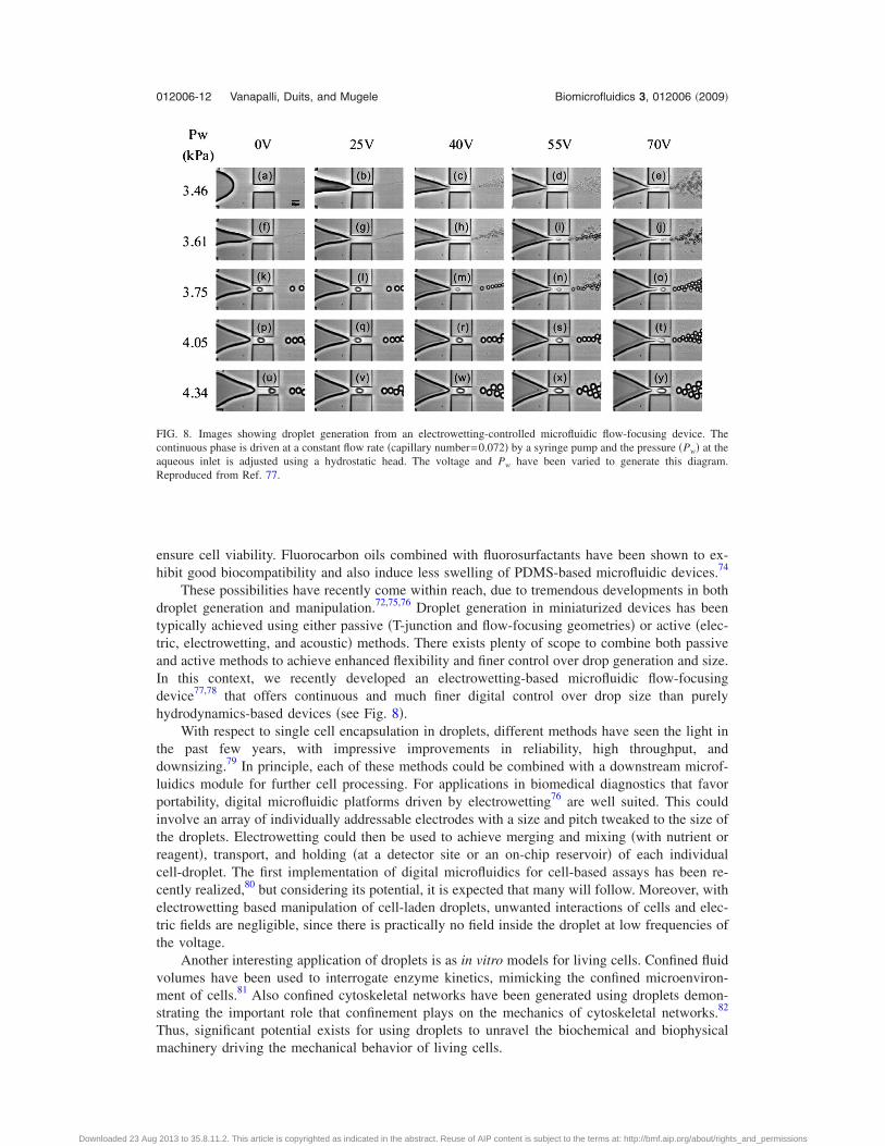
These possibilities have recently come within reach, due to tremendous developments in bothdroplet generation and manipulation.72,75,76 Droplet generation in miniaturized devices has beentypically achieved using either passive �T-junction and flow-focusing geometries� or active �elec-tric, electrowetting, and acoustic� methods. There exists plenty of scope to combine both passiveand active methods to achieve enhanced flexibility and finer control over drop generation and size.In this context, we recently developed an electrowetting-based microfluidic flow-focusingdevice77,78 that offers continuous and much finer digital control over drop size than purelyhydrodynamics-based devices �see Fig. 8�.
With respect to single cell encapsulation in droplets, different methods have seen the light inthe past few years, with impressive improvements in reliability, high throughput, anddownsizing.79 In principle, each of these methods could be combined with a downstream microf-luidics module for further cell processing. For applications in biomedical diagnostics that favorportability, digital microfluidic platforms driven by electrowetting76 are well suited. This couldinvolve an array of individually addressable electrodes with a size and pitch tweaked to the size ofthe droplets. Electrowetting could then be used to achieve merging and mixing �with nutrient orreagent�, transport, and holding �at a detector site or an on-chip reservoir� of each individualcell-droplet. The first implementation of digital microfluidics for cell-based assays has been re-cently realized,80 but considering its potential, it is expected that many will follow. Moreover, withelectrowetting based manipulation of cell-laden droplets, unwanted interactions of cells and elec-tric fields are negligible, since there is practically no field inside the droplet at low frequencies ofthe voltage.
Another interesting application of droplets is as in vitro models for living cells. Confined fluidvolumes have been used to interrogate enzyme kinetics, mimicking the confined microenviron-ment of cells.81 Also confined cytoskeletal networks have been generated using droplets demon-strating the important role that confinement plays on the mechanics of cytoskeletal networks.82
Thus, significant potential exists for using droplets to unravel the biochemical and biophysicalmachinery driving the mechanical behavior of living cells.
FIG. 8. Images showing droplet generation from an electrowetting-controlled microfluidic flow-focusing device. Thecontinuous phase is driven at a constant flow rate �capillary number=0.072� by a syringe pump and the pressure �Pw� at theaqueous inlet is adjusted using a hydrostatic head. The voltage and Pw have been varied to generate this diagram.Reproduced from Ref. 77.
012006-12 Vanapalli, Duits, and Mugele Biomicrofluidics 3, 012006 �2009�
Downloaded 23 Aug 2013 to 35.8.11.2. This article is copyrighted as indicated in the abstract. Reuse of AIP content is subject to the terms at: http://bmf.aip.org/about/rights_and_permissions
VII. CONCLUSIONS
Living cells are complex and dynamic systems. Understanding the coupling between the sheerbiological complexity and the cellular mechanical behavior requires tools capable of probing andmanipulating living cells. In this review, we have highlighted the importance of microfluidics as anenabling tool for fundamental investigations in cell mechanical behavior. While the current studiesprimarily make use of relatively simple microfluidic channels, the design flexibility of microflu-idics and the degree of control of both chemical and physical parameters will allow for analyzingthe cells’ response in unparalleled detail under conditions that will reflect more and more aspectsof the complexity of life. Physical models—theoretical and numerical—will have to be developedto model the cell mechanical behavior and to interpret quantitatively the information that becomesavailable from such experiments. For example, there is a need for quantitative modeling to extractmembrane and cytoskeleton mechanical properties from micofluidic manometer measurements. Inturn, numerical models can be used to optimize the design of dedicated microfluidic devices forextracting specific properties. Given the easy optical access, the full spectrum of optical-microscopy-based techniques for analyzing intracellular processes such as signaling pathways isreadily combined with microfluidics and thereby provides access to the regulatory network behindthe cell’s mechanical response. Simultaneously efforts need to be pursued to integrate establishedrheometric methods such as atomic force microscopy, particle-tracking microrheology, and mag-netic twisting cytometry into microfluidic devices in order to extract more specific mechanicalinformation. Insights from such combined studies may lead to therapeutic strategies for thecontrol and prevention of diseases and the development of miniaturized devices for biomedicaldiagnostics.
ACKNOWLEDGMENTS
We acknowledge the support from the Cell Stress Program at the University of Twente. We aregrateful to Dirk van den Ende for performing the numerical calculations reported in Fig. 5 andMichael J. Solomon from the University of Michigan for providing the preprint on the multilayermicrofluidic device for mechanical characterization of soft matter. S. A. V. thanks the Texas TechUniversity start-up funds for supporting this research.
1 C. Zhu, G. Bao, and N. Wang, Annu. Rev. Biomed. Eng. 2, 189 �2000�; G. Bao and S. Suresh, Nature Mater. 2, 715�2003�.
2 S. Kasas and G. Dietler, Pfluegers Arch. Eur. J. Physiol. 456, 13 �2008�.3 S. Suresh, Acta Biomater. 3, 413 �2007�.4 D. E. Discher, E. P. Janmey, and Y. L. Wang, Science 310, 1139 �2005�.5 S. E. Cross, Y. S. Jin, J. Rao, and J. K. Gimzewski, Nat. Nanotechnol. 2, 780 �2007�.6 G. Y. H. Lee and C. T. Lim, Trends Biotechnol. 25, 111 �2007�.7 G. B. Nash, C. S. Johnson, and H. J. Meiselman, Blood 63, 73 �1984�.8 D. E. Ingber, Ann. Med. 35, 564 �2003�.9 J. Guck, S. Schinkinger, B. Lincoln, F. Wottawah, S. Ebert, M. Romeyke, D. Lenz, H. M. Erickson, R. Ananthakrishnan,D. Mitchell, J. Kas, S. Ulvick, and C. Bilby, Biophys. J. 88, 3689 �2005�.
10 T. D. Pollard and G. G. Borisy, Cell 112, 453 �2003�; A. R. Bausch and K. Kroy, Nat. Phys. 2, 231 �2006�.11 P. F. Davies, Physiol. Rev. 75, 519 �1995�.12 A. S. French, Annu. Rev. Physiol. 54, 135 �1992�; P. G. Gillespie and R. G. Walker, Nature �London� 413, 194 �2001�;
O. P. Hamill and B. Martinac, Physiol. Rev. 81, 685 �2001�; P. A. Watson, FASEB J. 5, 2013 �1991�; N. Wang, J. P.Butler, and D. E. Ingber, Science 260, 1124 �1993�.
13 S. Kumar and P. R. LeDuc, Exp. Mech. 2007�; P. R. LeDuc and R. M. Bellin, Ann. Biomed. Eng. 34, 102 �2006�.14 P. Bursac, G. Lenormand, B. Fabry, M. Oliver, D. A. Weitz, V. Viasnoff, J. P. Butler, and J. J. Fredberg, Nature Mater.
4, 557 �2005�; B. D. Hoffman, G. Massiera, K. M. Van Citters, and J. C. Crocker, Proc. Natl. Acad. Sci. U.S.A. 103,10259 �2006�; K. E. Kasza, A. C. Rowat, J. Y. Liu, T. E. Angelini, C. P. Brangwynne, G. H. Koenderink, and D. A.Weitz, Curr. Opin. Cell Biol. 19, 101 �2007�; X. Trepat, L. H. Deng, S. S. An, D. Navajas, D. J. Tschumperlin, W. T.Gerthoffer, J. P. Butler, and J. J. Fredberg, Nature �London� 447, 592 �2007�; D. E. Ingber, J. Cell. Sci. 116, 1397�2003�; C. Sultan, D. Stamenovic, and D. E. Ingber, Ann. Biomed. Eng. 32, 520 �2004�.
15 K. J. Van Vliet, G. Bao, and S. Suresh, Acta Mater. 51, 5881 �2003�; T. P. Lele, J. E. Sero, B. D. Matthews, S. Kumar,S. Xia, M. Montoya-Zavala, T. Polte, D. Overby, N. Wang, and D. E. Ingber, Methods Cell Biol. 83, 443 �2007�.
16 D. C. Duffy, J. C. McDonald, O. J. A. Schueller, and G. M. Whitesides, Anal. Chem. 70, 4974 �1998�; Y. N. Xia and G.M. Whitesides, Annu. Rev. Mater. Sci. 28, 153 �1998�.
17 M. A. Unger, H. P. Chou, T. Thorsen, A. Scherer, and S. R. Quake, Science 288, 113 �2000�.18 G. M. Whitesides, Nature �London� 442, 368 �2006�; T. M. Squires and S. R. Quake, Rev. Mod. Phys. 77, 977 �2005�;
H. A. Stone, A. D. Stroock, and A. Ajdari, Annu. Rev. Fluid Mech. 36, 381 �2004�.
012006-13 Microfluidics and cells Biomicrofluidics 3, 012006 �2009�
Downloaded 23 Aug 2013 to 35.8.11.2. This article is copyrighted as indicated in the abstract. Reuse of AIP content is subject to the terms at: http://bmf.aip.org/about/rights_and_permissions
19 J. El-Ali, P. K. Sorger, and K. F. Jensen, Nature �London� 442, 403 �2006�; H. Andersson and A. van den Berg, Sens.Actuators B 92, 315 �2003�.
20 L. Kim, Y. C. Toh, J. Voldman, H. Yu, Lab Chip 7, 681 �2007�.21 F. Wolbers, P. ter Braak, S. Le Gac, R. Luttge, H. Andersson, I. Vermes, and A. van den Berg, Electrophoresis 27, 5073
�2006�.22 R. Davidsson, A. Boketoft, J. Bristulf, K. Kotarsky, B. Olde, C. Owman, M. Bengtsson, T. Laurell, and J. Emneus, Anal.
Chem. 76, 4715 �2004�.23 A. W. Blau and C. M. Ziegler, J. Biochem. Biophys. Methods 50, 15 �2001�; J. N. Lee, X. Jiang, D. Ryan, and G. M.
Whitesides, Langmuir 20, 11684 �2004�; A. Prokop, Z. Prokop, D. Schaffer, E. Kozlov, J. Wikswo, D. Cliffel, and F.Baudenbacher, Biomed. Microdevices 6, 325 �2004�; A. Tourovskaia, X. Figueroa-Masot, and A. Folch, Lab Chip 5, 14�2005�; R. Gomez-Sjoberg, A. A. Leyrat, D. M. Pirone, C. S. Chen, and S. R. Quake, Anal. Chem. 79, 8557 �2007�; N.Futai, W. Gu, J. W. Song, and S. Takayama, Lab Chip 6, 149 �2006�.
24 J. Komen, F. Wolbers, H. R. Franke, H. Andersson, I. Vermes, and A. van den Berg, Biomed. Microdevices 10, 727�2008�.
25 H. M. Yu, I. Meyvantsson, I. A. Shkel, and D. J. Beebe, Lab Chip 5, 1089 �2005�; P. J. Hung, P. J. Lee, P. Sabounchi,R. Lin, and L. P. Lee, Biotechnol. Bioeng. 89, 1 �2005�.
26 Y. S. Li, J. H. Haga, and S. Chien, J. Biomech. 38, 1949 �2005�.27 Z. R. Healy, N. H. Lee, X. Q. Gao, M. B. Goldring, P. Talalay, T. W. Kensler, and K. Konstantopoulos, Proc. Natl. Acad.
Sci. U.S.A. 102, 14010 �2005�.28 J. Voldman, M. Gray, M. Toner, and M. Schmidt, Anal. Chem. 74, 3984 �2002�.29 M. M. Wang, E. Tu, D. E. Raymond, J. M. Yang, H. C. Zhang, N. Hagen, B. Dees, E. M. Mercer, A. H. Forster, I. Kariv,
P. J. Marchand, and W. F. Butler, Nat. Biotechnol. 23, 83 �2005�.30 J. Hultstrom, O. Manneberg, K. Dopf, H. M. Hertz, H. Brismar, and M. Wiklund, Ultrasound Med. Biol. 33, 145 �2007�;
H. Li, J. R. Friend, and L. Y. Yeo, Biomaterials 28, 4098 �2007�.31 B. L. Gray, D. K. Lieu, S. D. Collins, R. L. Smith, and A. I. Barakat, Biomed. Microdevices 4, 9 �2002�.32 M. D. Frame and I. H. Sarelius, Microcirculation �Philadelphia� 7, 419 �2000�; G. Cinamon and R. Alon, J. Immunol.
Methods 273, 53 �2003�; M. D. S. Frame, G. B. Chapman, Y. Makino, and I. H. Sarelius, Biorheology 35, 245 �1998�;U. Y. Schaff, M. M. Q. Xing, K. K. Lin, N. Pan, N. L. Jeon, and S. I. Simon, Lab Chip 7, 448 �2007�; Y. Tanaka, Y.Kikukawa, K. Sato, Y. Sugh, and T. Kitamori, Anal. Sci. 23, 261 �2007�; E. W. K. Young, A. R. Wheeler, and C. A.Simmons, Lab Chip 7, 1759 �2007�; C. J. Ku, T. D. Oblak, and D. M. Spence, Anal. Chem. 80, 7543 �2008�; K. Liu,R. Pitchimani, D. Dang, K. Bayer, T. Harrington, and D. Pappas, Langmuir 24, 5955 �2008�; A. Shamloo, N. Ma, M. M.Poo, L. L. Sohn, and S. C. Heilshorn, Lab Chip 8, 1292 �2008�.
33 J. T. Borenstein, H. Terai, K. R. King, E. J. Weinberg, M. R. Kaazempur-Mofrad, and J. P. Vacanti, Biomed. Microde-vices 4, 167 �2002�.
34 J. W. Song, W. Gu, N. Futai, K. A. Warner, J. E. Nor, and S. Takayama, Anal. Chem. 77, 3993 �2005�.35 D. Huh, H. Fujioka, Y. C. Tung, N. Futai, R. Paine, J. B. Grotberg, and S. Takayama, Proc. Natl. Acad. Sci. U.S.A. 104,
18886 �2007�.36 M. Antia, T. Herricks, and P. K. Rathod, Cell. Microbiol. 10, 1968 �2008�.37 J. P. Shelby, J. White, K. Ganesan, P. K. Rathod, and D. T. Chiu, Proc. Natl. Acad. Sci. U.S.A. 100, 14618 �2003�.38 J. M. Higgins, D. T. Eddington, S. N. Bhatia, and L. Mahadevan, Proc. Natl. Acad. Sci. U.S.A. 104, 20496 �2007�.39 M. J. Rosenbluth, W. A. Lam, and D. A. Fletcher, Lab Chip 8, 1062 �2008�.40 X. Y. Zhu, L. Y. Chu, B. H. Chueh, M. W. Shen, B. Hazarika, N. Phadke, and S. Takayama, Analyst �Cambridge, U.K.�
129, 1026 �2004�; J. Atencia and D. J. Beebe, Lab Chip 6, 567 �2006�; S. D. Hudson, F. R. Phelan, M. D. Handler, J.T. Cabral, K. B. Migler, and E. J. Amis, Appl. Phys. Lett. 85, 335 �2004�; J. S. Lee, R. Dylla-Spears, N. P. Teclemariam,and S. J. Muller, Appl. Phys. Lett. 90, 074103 �2007�.
41 L. Yobas, K. C. Tang, S. E. Yong, and E. K. Z. Ong, Lab Chip 8, 660 �2008�; W. Gu, X. Y. Zhu, N. Futai, B. S. Cho,and S. Takayama, Proc. Natl. Acad. Sci. U.S.A. 101, 15861 �2004�.
42 A. D. Stroock, S. K. W. Dertinger, A. Ajdari, I. Mezic, H. A. Stone, and G. M. Whitesides, Science 295, 647 �2002�.43 A. Groisman and V. Steinberg, Nature �London� 410, 905 �2001�.44 X. M. Zhao, Y. N. Xia, and G. M. Whitesides, J. Mater. Chem. 7, 1069 �1997�.45 N. Q. Balaban, U. S. Schwarz, D. Riveline, P. Goichberg, G. Tzur, I. Sabanay, D. Mahalu, S. Safran, A. Bershadsky, L.
Addadi, and B. Geiger, Nat. Cell Biol. 3, 466 �2001�.46 I. B. Bischofs and U. S. Schwarz, Proc. Natl. Acad. Sci. U.S.A. 100, 9274 �2003�.47 J. Solon, I. Levental, K. Sengupta, P. C. Georges, and P. A. Janmey, Biophys. J. 93, 4453 �2007�.48 A. J. Engler, S. Sen, H. L. Sweeney, and D. E. Discher, Cell 126, 677 �2006�.49 D. N. Hohne, J. G. Younger, and M. J. Solomon, “Flexible microfluidic device for mechanical property characterization
of soft viscoelastic solids such as bacterial biofilms,” Langmuir�submitted�.50 L. G. Griffith and M. A. Swartz, Nat. Rev. Mol. Cell Biol. 7, 211 �2006�.51 S. R. Khetani and S. N. Bhatia, Nat. Biotechnol. 26, 120 �2008�.52 R. S. Kane, S. Takayama, E. Ostuni, D. E. Ingber, and G. M. Whitesides, Biomaterials 20, 2363 �1999�.53 S. A. Vanapalli, D. Wijnperle, A. van den Berg, F. Mugele, and M. H. G. Duits, “Programmable structured elastomeric
membranes as a multifunctional microfluidic tool,” Lab Chip �submitted�.54 S. Takayama, E. Ostuni, P. R. LeDuc, K. Naruse, D. E. Ingber, and G. M. Whitesides, Nature �London� 411, 1016
�2001�.55 B. Kuczenski, P. R. LeDuc, and W. C. Messner, Lab Chip 7, 647 �2007�.56 F. Wang, H. Wang, J. Wang, H. Y. Wang, P. L. Rummel, S. V. Garimella, and C. Lu, Biotechnol. Bioeng. 100, 150
�2008�.57 S. K. W. Dertinger, D. T. Chiu, N. L. Jeon, and G. M. Whitesides, Anal. Chem. 73, 1240 �2001�; D. Irimia, D. A. Geba,
and M. Toner, Anal. Chem. 78, 3472 �2006�; K. Campbell and A. Groisman, Lab Chip 7, 264 �2007�.58 M. Abkarian, M. Faivre, and H. A. Stone, Proc. Natl. Acad. Sci. U.S.A. 103, 538 �2006�.59 N. Bao, Y. H. Zhan, and C. Lu, Anal. Chem. 80, 7714 �2008�.
012006-14 Vanapalli, Duits, and Mugele Biomicrofluidics 3, 012006 �2009�
Downloaded 23 Aug 2013 to 35.8.11.2. This article is copyrighted as indicated in the abstract. Reuse of AIP content is subject to the terms at: http://bmf.aip.org/about/rights_and_permissions
60 A. Drochon, Med. Eng. Phys. 27, 157 �2005�; W. G. Lee, H. Bang, H. Yun, J. Lee, J. Park, J. K. Kim, S. Chung, S. Cho,C. Chung, D. C. Han, and J. K. Chang, Lab Chip 7, 516 �2007�.
61 N. Korin, A. Bransky, and U. Dinnar, J. Biomech. 40, 2088 �2007�; S. C. Gifford, M. G. Frank, J. Derganc, C. Gabel,R. H. Austin, T. Yoshida, and M. W. Bitensky, Biophys. J. 84, 623 �2003�.
62 H. Kiesewetter, U. Dauer, P. Teitel, H. Schmidschonbein, and R. Trapp, Biorheology 19, 737 �1982�.63 R. S. Frank and R. M. Hochmuth, J. Biomech. 109, 103 �1987�; R. S. Frank and M. A. Tsai, J. Biomech. 112, 277
�1990�.64 A. Groisman, M. Enzelberger, and S. R. Quake, Science 300, 955 �2003�.65 S. A. Vanapalli, D. van den Ende, M. H. G. Duits, and F. Mugele, Appl. Phys. Lett. 90, 114109 �2007�.66 S. A. Vanapalli, A. G. Banpurkar, D. van den Ende, M. H. G. Duits, and F. Mugele, “Hydrodynamic resistance of single
confined moving drops in rectangular microchannels” Lab Chip67 J. Guck, R. Ananthakrishnan, H. Mahmood, T. J. Moon, C. C. Cunningham, and J. Kas, Biophys. J. 81, 767 �2001�.68 O. du Roure, A. Saez, A. Buguin, R. H. Austin, P. Chavrier, P. Siberzan, and B. Ladoux, Proc. Natl. Acad. Sci. U.S.A.
102, 2390 �2005�.69 J. L. Tan, J. Tien, D. M. Pirone, D. S. Gray, K. Bhadriraju, and C. S. Chen, Proc. Natl. Acad. Sci. U.S.A. 100, 1484
�2003�.70 N. Sniadecki, A. Anguelouch, M. T. Yang, C. M. Lamb, Z. Liu, S. B. Kirschner, Y. Liu, D. H. Reich, and C. S. Chen,
Proc. Natl. Acad. Sci. U.S.A. 104, 14553 �2007�.71 Y. C. Kim, S. J. Park, and J. K. Park, Ann. Phys. 133, 1432 �2008�.72 S. Y. Teh, R. Lin, L. H. Hung, and A. P. Lee, Lab Chip 8, 198 �2008�; G. F. Christopher and S. L. Anna, J. Phys. D 40,
R319 �2007�.73 H. Song, D. L. Chen, and R. F. Ismagilov, Angew. Chem., Int. Ed. 45, 7336 �2006�.74 S. L. Roach, H. Song, and R. F. Ismagilov, Anal. Chem. 77, 785 �2005�; C. Holtze, A. C. Rowat, J. J. Agresti, J. B.
Hutchison, F. E. Angile, C. H. Schmitz, S. Koester, H. Duan, K. J. Humphry, R. A. Scanga, J. S. Johnson, D. Pisignano,and D. A. Weitz, Lab Chip 8, 1632 �2008�.
75 F. Mugele and J. C. Baret, J. Phys.: Condens. Matter 17, R705 �2005�.76 R. B. Fair, Microfluid. Nanofluid. 3, 245 �2007�.77 H. Gu, F. Malloggi, S. A. Vanapalli, and F. Mugele, Appl. Phys. Lett. 93, 183507 �2008�.78 F. Malloggi, S. A. Vanapalli, H. Gu, D. van den Ende, and F. Mugele, J. Phys.: Condens. Matter 19, 462101 �2007�.79 J. F. Edd, D. Di Carlo, K. J. Humphry, S. Koster, D. Irimia, D. A. Weitz, and M. Toner, Lab Chip 8, 1262 �2008�; M.
Chabert and J. L. Viovy, Proc. Natl. Acad. Sci. U.S.A. 105, 3191 �2008�; M. Y. He, J. S. Edgar, G. D. M. Jeffries, R. M.Lorenz, J. P. Shelby, and D. T. Chiu, Anal. Chem. 77, 1539–1544 �2005�.
80 I. Barbuloviv-Nad, H. Yang, P. S. Park, and A. R. Wheeler, Lab Chip 8, 519 �2008�.81 Y. Rondelez, G. Tresset, K. V. Tabata, H. Arata, H. Fujita, S. Takeuchi, and H. Noji, Nat. Biotechnol. 23, 361 �2005�; S.
Y. Jung, Y. Liu, and C. P. Collier, Langmuir 24, 4439 �2008�; H. Song and R. F. Ismagilov, J. Am. Chem. Soc. 125,14613 �2003�.
82 M. M. A. E. Claessens, R. Tharmann, K. Kroy, and A. R. Bausch, Nat. Phys. 2, 186 �2006�.
012006-15 Microfluidics and cells Biomicrofluidics 3, 012006 �2009�
Downloaded 23 Aug 2013 to 35.8.11.2. This article is copyrighted as indicated in the abstract. Reuse of AIP content is subject to the terms at: http://bmf.aip.org/about/rights_and_permissions