Embed Size (px)
Citation preview
The Next Generation of Ionics® Solutions
Micromax™ 7000
Homeowner’s ManualPuronics Reverse Osmosis System
System Tested and Certified by the Water Quality Association(WQA) against NSF/ANSI Standard 58 for the reduction of Cysts,Lead, Pentavalent Arsenic, Cadmium, Hexavalent Chromium,Trivalent Chromium, Selenium, Nitrites/Nitrates and TotalDissolved Solids (TDS) and against NSF/ANSI Standard 42 for theaesthetic reduction of Chlorine Taste and Odor Particulates.
Puronics Water Systems, Inc.
5775 Las Positas Rd., Livermore, California 94551-7819 USA(800) 339-8780www.puronics.com
© Copyright 2011. Puronics Water Systems, Inc. All rights reserved. S2-12/11
IMPORTANTthis booklet contains your owner Limited Warranty Card. make sure this Warranty Card isfilled out by your Dealer and returned to puronics Water systems, inc. within 30 days ofinstallation to assure proper warranty registration.
Questions about your warranty registration may be answered by writing to:
Warranty Registration Dept.c/o Puronics Water Systems, Inc.
5775 Las Positas RoadLivermore, CA 94551
You can also register your warranty online at www.puronics.com.
Your Puronics® Dealer is . . .
© Copyright 2011 puroniCs Water systems, inC.2
Congratulationspuronics® welcomes you to a new, carefree way of life with filtered water. you can take prideand satisfaction knowing that you own the very best.
We are proud you have selected the puronics® ro system for your home. your soundjudgment is supported by the wide acceptance received for these systems throughout theworld. more and more quality conscious homeowners are purchasing puronics® roequipment because of its’ superior performance and premium quality workmanship.
the following pages of this booklet will introduce you to your new puronics® ro system byexplaining operation, care and maintenance.
at puronics®, we not only care for your water . . . we care for your family.
Puronics® Water Systems, Inc.
© Copyright 2011 puroniCs Water systems, inC.3
Puronics Water Systems, Inc.5775 Las Positas RoadLivermore, CA 94551(800) 339-8780
www.puronics.com
© Copyright 2011 puroniCs Water systems, inC.4
NotIceS & SafetY INformatIoN
• these filters are not water purifiers. Do not use with water that is microbiologically unsafe or of unknown
quality without adequate disinfection before or after the system. systems certified for Cyst reduction
may be used on disinfected waters that may contain filterable Cysts.
• this unit is not designed to filter sulfur (rotten egg odor). use of carbon filters to treat sulfur may
intensify taste/odor problems.
• please comply with all state and local regulations regarding the installation of water treatment devices.
• the contaminants or other substances reduced by the water filter device are not necessarily in your water.
• Do not install this system in direct sunlight or in an area where it may be exposed to harsh chemicals or
may be subjected to being dropped, knocked over, and struck by moving equipment or any other items
that may cause damage.
• Do not install this system near any source of heat. excessive heat can cause housing failure and water
damage to surrounding area.
• Do not install this system on the “hot” water line. Limit incoming water temperature to 37.8°C (100°F).
Failure to limit incoming water temperature may result in housing failure and filter damage.
• this system must be protected against freezing, which can cause cracking of the filter and water damage
to surrounding area.
• pre and post filters must be replaced annually. membrane filters must be replaced at least every 5 years.
Failure to replace these filters as recommended may result in housing failure and water damage to
surrounding area.
• this system has a maximum pressure rating of 100 psi, if at any time your pressure may exceed 100 psi a
pressure regulator must be installed before the filter, if any time. it is recommended that the pressure
regulator be set at 75 psi (517 kpa) or less. this will guard against the pressure exceeding the maximum
rating at any time and damage to the system, which may result in housing failure and water damage to
surrounding area.

1 This system has been tested for the treatment of water containing pentavalent arsenic (also known as As(V), As(+5) or arsenate) at concentrations of 0.050 mg/L or less. This system reduces pentavalent arsenic, but may not remove other forms of arsenic. This system is to be used on watersupplies containing a detectable free chlorine residual at the system inlet or on water supplies that have been demonstrated to contain only pentavalent arsenic. Treatment with chloramines (combined chlorine) is not sufficient to ensure complete conversion of trivalent arsenic to pentavalentarsenic. Please see Arsenic Fact Sheet for further information.
2 This system is acceptable for treatment of influent concentrations of no more than 27 mg/ nitrate and 3 mg/L nitrite in combination measured as N and is certified for nitrate/nitrate reduction only for water supplies with a pressure of 280 kPa (40 psig) or greater.
3 Units are not certified on water supplies with pressure less than 40 psi (280kPa). A booster pump is strongly recommended.
4 Efficiency rating means the percentage of the influent water to the system that is available to the user as reverse osmosis treated water under operating conditions that approximate typical daily usage.
5 Recovery rate means the percentage of the influent water to the membrane portion of the system that is available to the user as reverse osmosis treated water when the system is operated without a storage tank or when the storage tank is bypassed.
Puronics® Reverse Osmosis Water Filtration SystemModel: Micromax™ 7000
with Filter Cartridge W-PN-1001 and Membrane Cartridge W-PN-1002
This filtration system has been tested and certified according toNSF/ANSI Standard 42 & 58 by WQA for the reduction ofsubstances listed below, as verified and substantiated by test data.The concentration of the indicated substances in the water enteringthe system was reduced to a concentration less than or equal tothe permissable limit for leaving the system, as specified inNSF/ANSI Standards 42 & 58. Please see warranty insert formanufacturer's limited warranty. Please see installation instructionsfor internal operation and maintenance requirements.
Performance Data Sheet
Efficiency Rate: 19.0%4 Recovery Rate: 30.6%5 Daily Production Rate: 35 Gallons per DayOperating Temperature: Min 40°F / 4°C - Max 100°F / 38°C Operating Pressure: 40-100 psi (276-690 kPa)Laboratory Test Conditions: pH: 6.5 – 8.5 Water Temperature: 72°F / 23°C - 75°F / 24°C Actual performance may vary with local water conditions.Do not use with water that is microbiologically unsafe or of unknown water quality without adequate disinfection before or afterthe system. Systems certified for cyst reduction may be used on disinfected waters that may contain filterable cysts.
Arsenic (Pentavalent)1 0.05 +/- 10% 0.01 mg 80.0% 89.7% 95.4%Cadmium 0.03 +/- 10% 0.0005 mg 83.3% 96.1% 99.1%Chromium (Trivalent) 0.30 +/- 10% 0.05 mg 99.8% 99.9%Chromium (Hexavalent) 0.30 +/- 10% 0.05 mg 83.3% 81.0% 98.9%Lead 0.15 +/- 10% 0.010 mg 93.3% 98.7% 99.6%Nitrate plus Nitrite2 30.0 +/- 10% 10.0 mg 63.3% 63.3% 63.3%Selenium 0.10 +/- 10% 0.05 mg 99.0% 99.0%Total Dissolved Solids 750 +/- 40 187 75.0% 96.6% 97.5%Reduction Requirements:
Cysts Minimum 50,000 2,500 99.95% 99.95% 99.95%oocysts/liter
NSF/ANSI Standard 42 Aesthetic Effects
NSF/ANSI Standard 58 Health Effects
Taste & Odor,Aesthetic Chlorine 2 mg 1 mg 50% 94.8% 97.4%
Particulate Class III > 10,000 particles 1,500 particles(5 um to < 15 um) per ml per ml 85% 98.0% 99.7%
ActualAveragePercentReduction
ActualMinimumPercentReduction
US EPA Maximum PermissibleWater Concentration/
% Reduction
Influent ChallengeConcentration(mg./liter
unless specified)Substance
Arsenic Fact SheetArsenic (As) is a naturally occurring contaminant found in many ground waters. It generally occurs in two forms (valences oroxidations states): pentavalent arsenic (also known as As(V), As(+5), or arsenate) and trivalent arsenic (also known as As(III),As (+3), or arsenite.) In natural ground water, arsenic may exist as trivalent arsenic, pentavalent arsenic, or a combinationof both. Although both forms of arsenic are potentially harmful to human health, trivalent arsenic is considered more harmfulthan pentavalent arsenic. More information about arsenic and its toxicity can be found on the U.S. Environmental ProtectionAgency website at http:www.epa.gov/safewater/arsenic.html.
Trivalent arsenic is generally more difficult to remove from drinking water than pentavalent arsenic. Trivalent arsenic can beconverted to pentavalent arsenic in the presence of an effective oxidant such as free chlorine.
The arsenic in water containing detectable free chlorine or that has been treated with another effective oxidant will be in thepentavalent arsenic form. Treatment with chloramine (combined chlorine) is not sufficient to ensure complete conversion oftrivalent arsenic to pentavalent arsenic.
Consumers using public water supplies can contact their utility to verify whether free chlorine treatment chemicals are beingused. Private water supplies and waters that do not have detectable free chlorine residuals should be analyzed to determinethe form(s) of arsenic present and the potential need for oxidation of trivalent arsenic to pentavalent arsenic.
Arsenic does not generally impart color, taste, or smell to water, therefore, it can only be detected by a chemical analyticaltest. Public water supplies are required to monitor treated water for total arsenic (trivalent arsenic plus pentavalent arsenic)and the results are available to the public from the utility. Consumers using private water sources will need to makearrangements for testing. A total arsenic test usually costs about $15-$30 and it is recommended a certified laboratory conducttest. Local health departments or environmental protection agencies can help provide consumers with a list of certifiedlaboratories. Some laboratories may also be able to analyze specifically for (speciate) the forms of arsenic present in a watersample if requested and ordering information.
Water treatment systems are tested under laboratory conditions and found to reduce either 0.30 mg/L or 0.050 mg/L (refer tothe product listing for influent tested levels) in the test water to less than 0/0.010 mg/L, under standard testing conditions.Actual performance of the system may vary depending on specific water quality conditions at the consumer’s installation.Following installation of this system, the consumer should have the treated water tested for total arsenic to verify arsenicreduction is being achieved and the system is functioning properly.
The pentavalent arsenic removal component of this system must be replaced at the end of its’ useful life.Replacement component(s) can be purchased from the original source of this system (retailer or distributor), from other sourcesof this treatment system, or directly from the manufacturer. Refer to the installation and operation manual of you water treatmentdevice to obtain replacement frequency and ordering information.
© Copyright 2011 puroniCs Water systems, inC.5

Teflon® Tape
Red Tube
4’ of 1/4” White TubeV
Quick ConnectLocking Tabs
MembraneFilter(red)
PreFilter(green)
PostFilter(green)
Manifold
Shroud
Drain FittingW
RO System
reQUIreD tooLS & materIaLS
• tape measure • utility Knife• phillips head screwdriver • 1/8” and 7/32” Drill Bits• adjustable Wrench • Center punch• File • safety glasses• pencil • masking tape• pan or Bucket • Compression Cap (Optional – for Kitchen Spray Hose Connector)
PacKaGe coNteNtS
© Copyright 2011 puroniCs Water systems, inC.6
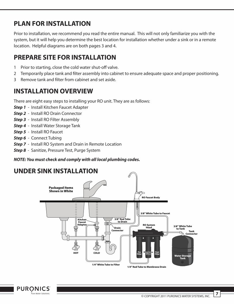
PLaN for INStaLLatIoNprior to installation, we recommend you read the entire manual. this will not only familiarize you with thesystem, but it will help you determine the best location for installation whether under a sink or in a remotelocation. helpful diagrams are on both pages 3 and 4.
PrePare SIte for INStaLLatIoN1 prior to starting, close the cold water shut-off valve.2 temporarily place tank and filter assembly into cabinet to ensure adequate space and proper positioning.3 remove tank and filter from cabinet and set aside.
INStaLLatIoN oVerVIeWthere are eight easy steps to installing your ro unit. they are as follows:Step 1 - install Kitchen Faucet adapterStep 2 - install ro Drain ConnectorStep 3 - install ro Filter assemblyStep 4 - install Water storage tankStep 5 - install ro FaucetStep 6 - Connect tubing Step 7 - install ro system and Drain in remote LocationStep 8 - sanitize, pressure test, purge system
NOTE: You must check and comply with all local plumbing codes.
UNDer SINK INStaLLatIoN
3/8” Red Tubeto Drain
1/4” Red Tube to Membrane Drain
MembraneMembraneFilterFilter
MembraneFilter
PreFilter
PostFilter
© Copyright 2011 puroniCs Water systems, inC.7
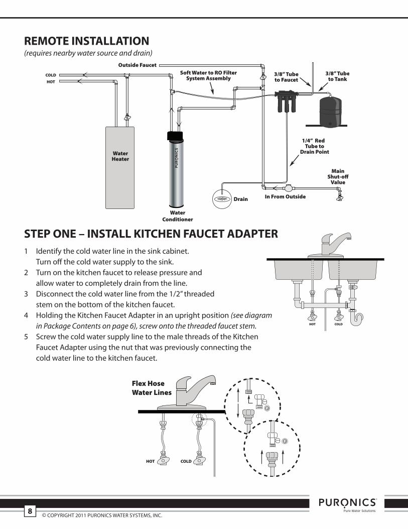
remote INStaLLatIoN(requires nearby water source and drain)
SteP oNe – INStaLL KItcHeN faUcet aDaPter1 identify the cold water line in the sink cabinet.
turn off the cold water supply to the sink. 2 turn on the kitchen faucet to release pressure and
allow water to completely drain from the line.3 Disconnect the cold water line from the 1/2” threaded
stem on the bottom of the kitchen faucet.4 holding the Kitchen Faucet adapter in an upright position (see diagram
in Package Contents on page 6), screw onto the threaded faucet stem.5 screw the cold water supply line to the male threads of the Kitchen
Faucet adapter using the nut that was previously connecting the cold water line to the kitchen faucet.
3/8” 3/8”
WaterConditioner
© Copyright 2011 puroniCs Water systems, inC.8
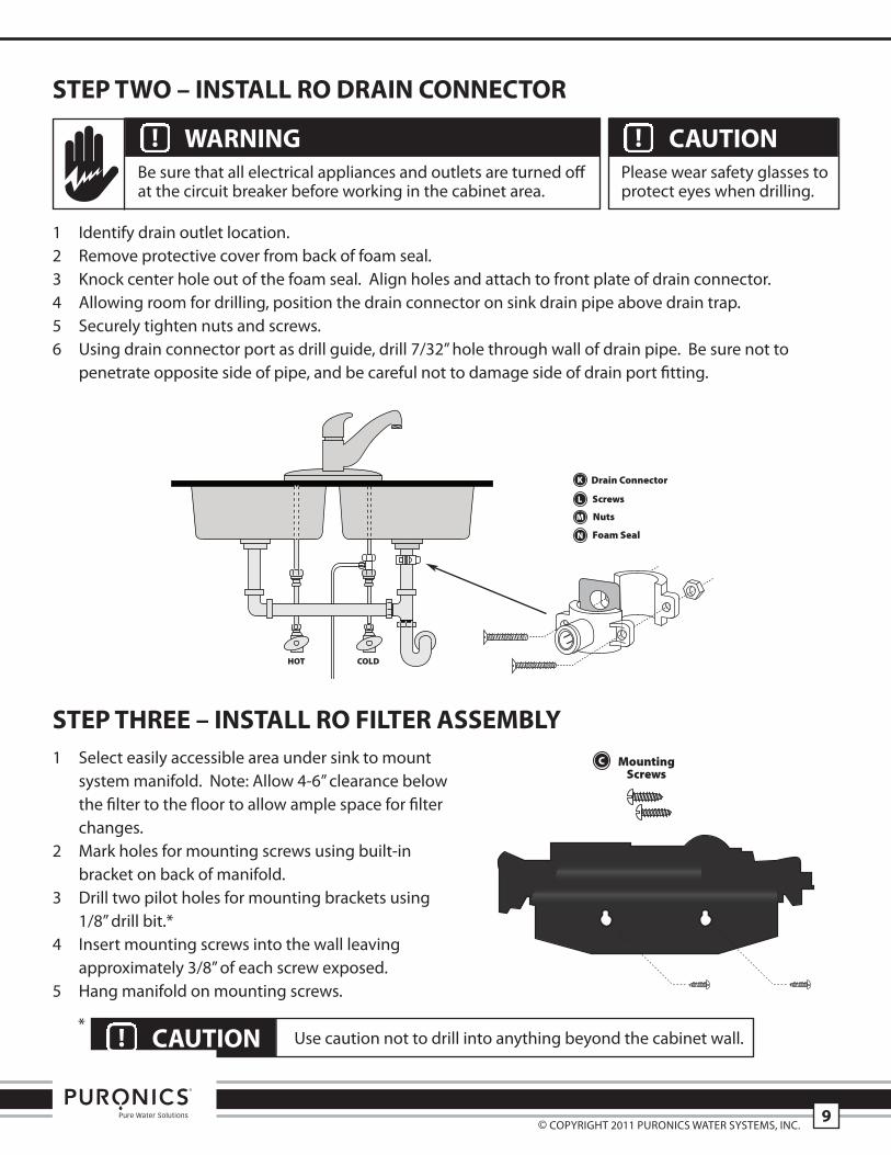
SteP tWo – INStaLL ro DraIN coNNector
1 identify drain outlet location.2 remove protective cover from back of foam seal.3 Knock center hole out of the foam seal. align holes and attach to front plate of drain connector.4 allowing room for drilling, position the drain connector on sink drain pipe above drain trap.5 securely tighten nuts and screws.6 using drain connector port as drill guide, drill 7/32” hole through wall of drain pipe. Be sure not to
penetrate opposite side of pipe, and be careful not to damage side of drain port fitting.
SteP tHree – INStaLL ro fILter aSSemBLY1 select easily accessible area under sink to mount
system manifold. note: allow 4-6” clearance belowthe filter to the floor to allow ample space for filterchanges.
2 mark holes for mounting screws using built-inbracket on back of manifold.
3 Drill two pilot holes for mounting brackets using1/8” drill bit.*
4 insert mounting screws into the wall leavingapproximately 3/8” of each screw exposed.
5 hang manifold on mounting screws.
WarNING Be sure that all electrical appliances and outlets are turned offat the circuit breaker before working in the cabinet area.
! caUtIoN please wear safety glasses toprotect eyes when drilling.
!
caUtIoN! use caution not to drill into anything beyond the cabinet wall.*
© Copyright 2011 puroniCs Water systems, inC.9
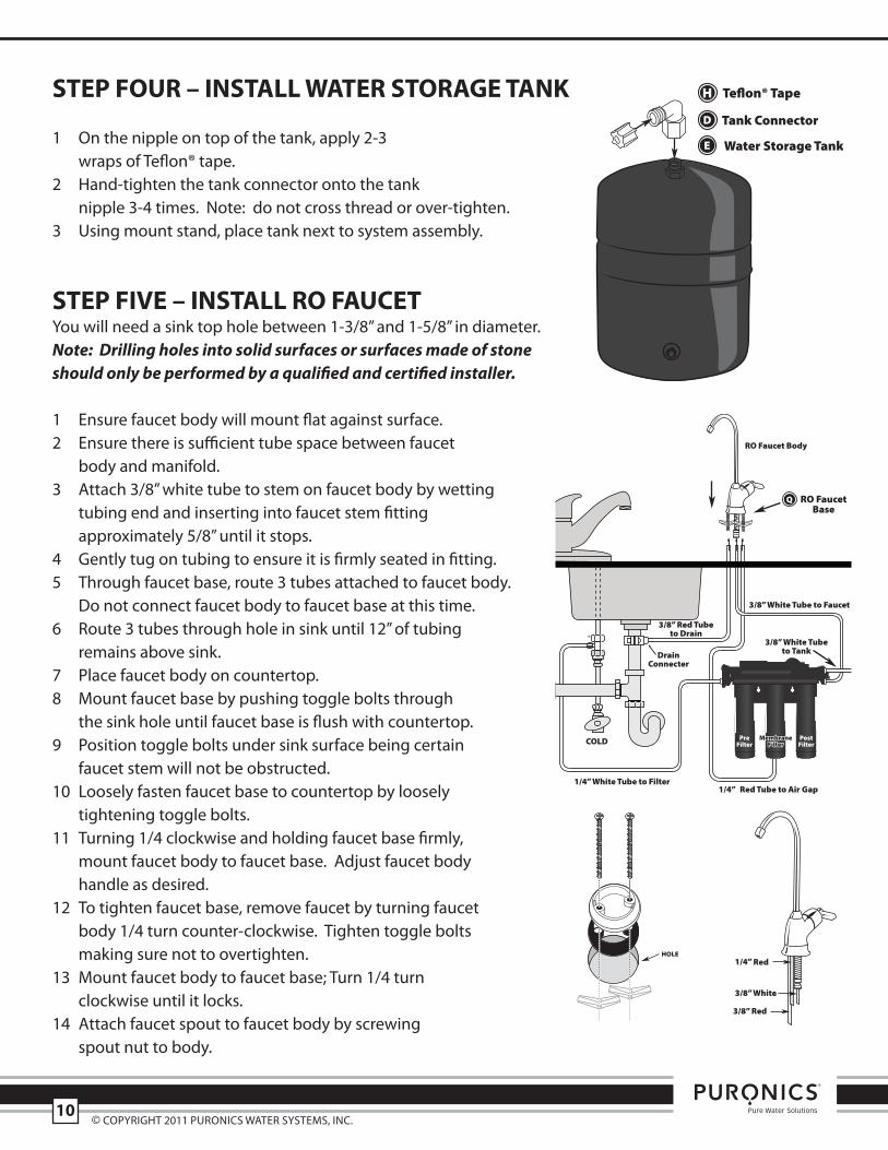
SteP foUr – INStaLL Water StoraGe taNK
1 on the nipple on top of the tank, apply 2-3 wraps of teflon® tape.
2 hand-tighten the tank connector onto the tank nipple 3-4 times. note: do not cross thread or over-tighten.
3 using mount stand, place tank next to system assembly.
SteP fIVe – INStaLL ro faUcetyou will need a sink top hole between 1-3/8” and 1-5/8” in diameter. Note: Drilling holes into solid surfaces or surfaces made of stoneshould only be performed by a qualified and certified installer.
1 ensure faucet body will mount flat against surface.2 ensure there is sufficient tube space between faucet
body and manifold. 3 attach 3/8” white tube to stem on faucet body by wetting
tubing end and inserting into faucet stem fitting approximately 5/8” until it stops.
4 gently tug on tubing to ensure it is firmly seated in fitting.5 through faucet base, route 3 tubes attached to faucet body.
Do not connect faucet body to faucet base at this time.6 route 3 tubes through hole in sink until 12” of tubing
remains above sink.7 place faucet body on countertop.8 mount faucet base by pushing toggle bolts through
the sink hole until faucet base is flush with countertop. 9 position toggle bolts under sink surface being certain
faucet stem will not be obstructed. 10 Loosely fasten faucet base to countertop by loosely
tightening toggle bolts.11 turning 1/4 clockwise and holding faucet base firmly,
mount faucet body to faucet base. adjust faucet body handle as desired.
12 to tighten faucet base, remove faucet by turning faucet body 1/4 turn counter-clockwise. tighten toggle bolts making sure not to overtighten.
13 mount faucet body to faucet base; turn 1/4 turn clockwise until it locks.
14 attach faucet spout to faucet body by screwing spout nut to body.
3/8” White Tube to Faucet
3/8” Red Tubeto Drain
3/8” White Tubeto Tank
3/8” White
3/8” Red
MembraneMembraneFilterFilter
MembraneFilter
PreFilter
PostFilter
H Teflon® Tape
© Copyright 2011 puroniCs Water systems, inC.10
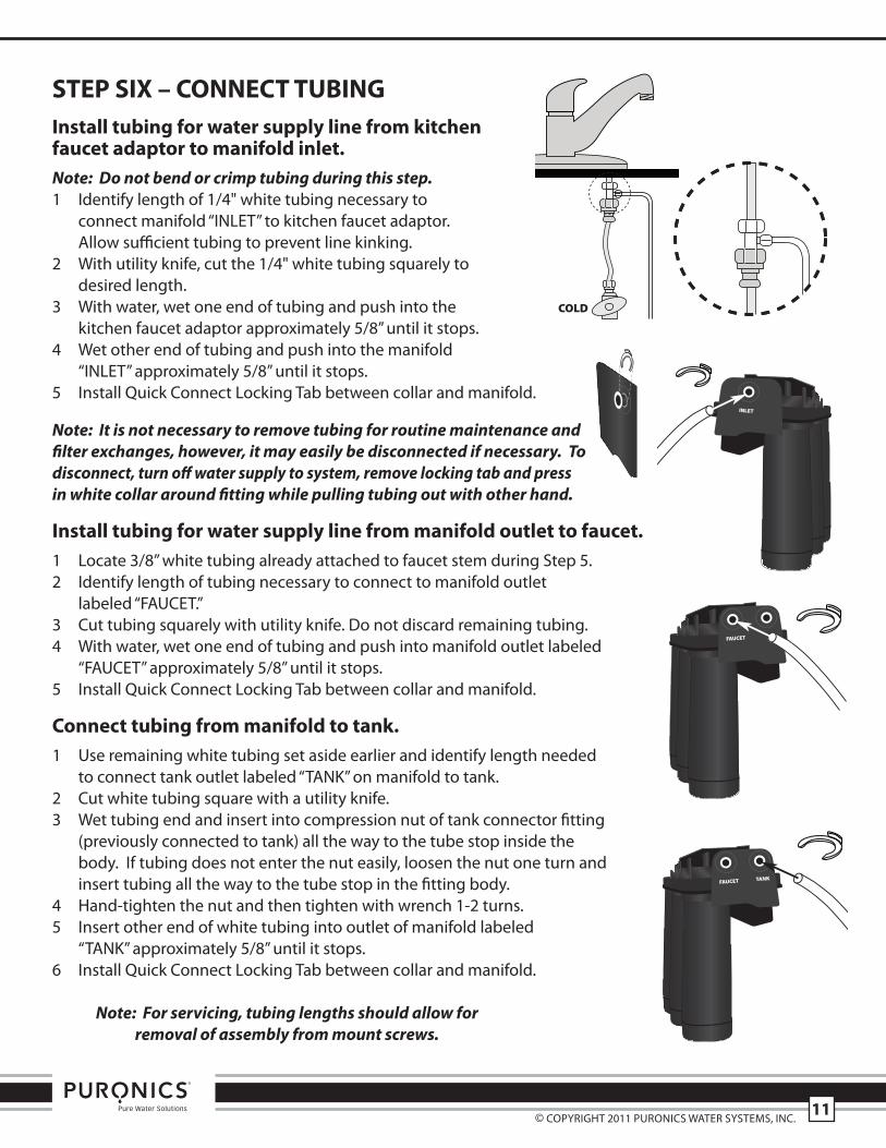
INLET
SteP SIX – coNNect tUBINGInstall tubing for water supply line from kitchenfaucet adaptor to manifold inlet.Note: Do not bend or crimp tubing during this step.1 identify length of 1/4" white tubing necessary to
connect manifold “inLet” to kitchen faucet adaptor. allow sufficient tubing to prevent line kinking.
2 With utility knife, cut the 1/4" white tubing squarely to desired length.
3 With water, wet one end of tubing and push into the kitchen faucet adaptor approximately 5/8” until it stops.
4 Wet other end of tubing and push into the manifold “inLet” approximately 5/8” until it stops.
5 install Quick Connect Locking tab between collar and manifold.
Note: It is not necessary to remove tubing for routine maintenance andfilter exchanges, however, it may easily be disconnected if necessary. Todisconnect, turn off water supply to system, remove locking tab and pressin white collar around fitting while pulling tubing out with other hand.
Install tubing for water supply line from manifold outlet to faucet.1 Locate 3/8” white tubing already attached to faucet stem during step 5. 2 identify length of tubing necessary to connect to manifold outlet
labeled “FauCet.”3 Cut tubing squarely with utility knife. Do not discard remaining tubing.4 With water, wet one end of tubing and push into manifold outlet labeled
“FauCet” approximately 5/8” until it stops. 5 install Quick Connect Locking tab between collar and manifold.
connect tubing from manifold to tank.1 use remaining white tubing set aside earlier and identify length needed
to connect tank outlet labeled “tanK” on manifold to tank.2 Cut white tubing square with a utility knife. 3 Wet tubing end and insert into compression nut of tank connector fitting
(previously connected to tank) all the way to the tube stop inside thebody. if tubing does not enter the nut easily, loosen the nut one turn andinsert tubing all the way to the tube stop in the fitting body.
4 hand-tighten the nut and then tighten with wrench 1-2 turns.5 insert other end of white tubing into outlet of manifold labeled
“tanK” approximately 5/8” until it stops.6 install Quick Connect Locking tab between collar and manifold.
Note: For servicing, tubing lengths should allow for removal of assembly from mount screws.
FAUCET
FAUCET TANK
© Copyright 2011 puroniCs Water systems, inC.11
MembraneMembraneFilterFilter
MembraneFilter
PreFilter
PostFilter
1/4” White Tube to Filter
3/8” Red Tubeto Drain
3/8” White Tubeto Tank
3/8” White Tube to Faucet
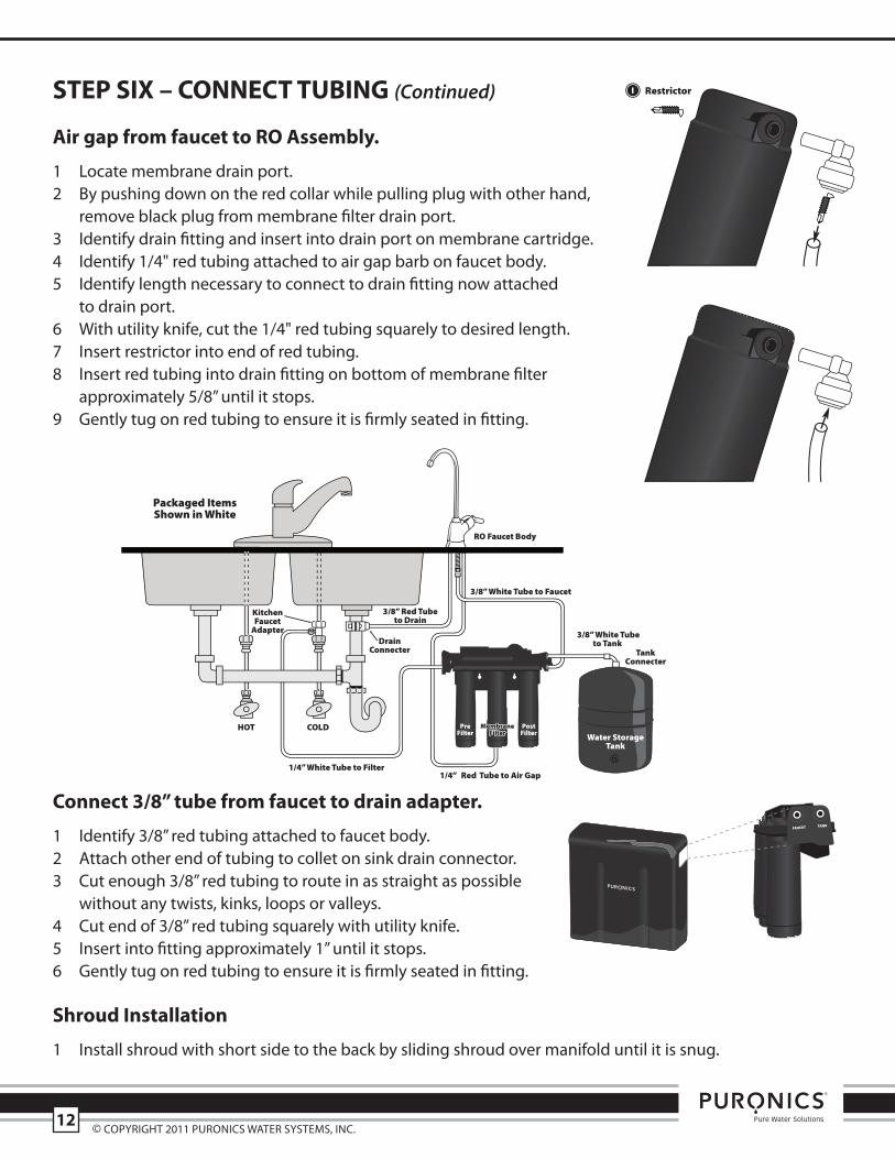
SteP SIX – coNNect tUBING (Continued)
air gap from faucet to ro assembly.
1 Locate membrane drain port.2 By pushing down on the red collar while pulling plug with other hand,
remove black plug from membrane filter drain port.3 identify drain fitting and insert into drain port on membrane cartridge.4 identify 1/4" red tubing attached to air gap barb on faucet body.5 identify length necessary to connect to drain fitting now attached
to drain port.6 With utility knife, cut the 1/4" red tubing squarely to desired length.7 insert restrictor into end of red tubing.8 insert red tubing into drain fitting on bottom of membrane filter
approximately 5/8” until it stops.9 gently tug on red tubing to ensure it is firmly seated in fitting.
connect 3/8” tube from faucet to drain adapter.
1 identify 3/8” red tubing attached to faucet body.2 attach other end of tubing to collet on sink drain connector.3 Cut enough 3/8” red tubing to route in as straight as possible
without any twists, kinks, loops or valleys.4 Cut end of 3/8” red tubing squarely with utility knife.5 insert into fitting approximately 1” until it stops.6 gently tug on red tubing to ensure it is firmly seated in fitting.
Shroud Installation
1 install shroud with short side to the back by sliding shroud over manifold until it is snug.
© Copyright 2011 puroniCs Water systems, inC.12
FAUCET TANK
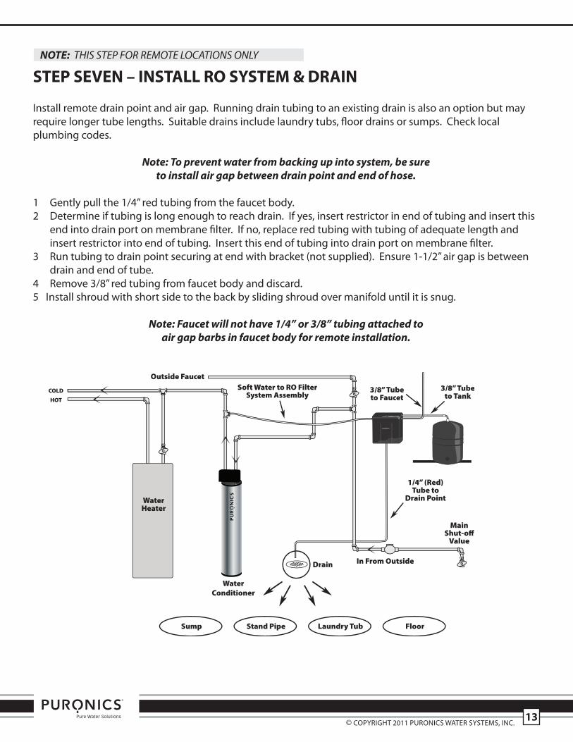
NOTE: THIS STEP FOR REMOTE LOCATIONS ONLY
SteP SeVeN – INStaLL ro SYStem & DraIN
install remote drain point and air gap. running drain tubing to an existing drain is also an option but mayrequire longer tube lengths. suitable drains include laundry tubs, floor drains or sumps. Check localplumbing codes.
Note: To prevent water from backing up into system, be sureto install air gap between drain point and end of hose.
1 gently pull the 1/4” red tubing from the faucet body.2 Determine if tubing is long enough to reach drain. if yes, insert restrictor in end of tubing and insert this
end into drain port on membrane filter. if no, replace red tubing with tubing of adequate length andinsert restrictor into end of tubing. insert this end of tubing into drain port on membrane filter.
3 run tubing to drain point securing at end with bracket (not supplied). ensure 1-1/2” air gap is betweendrain and end of tube.
4 remove 3/8” red tubing from faucet body and discard.5 install shroud with short side to the back by sliding shroud over manifold until it is snug.
Note: Faucet will not have 1/4” or 3/8” tubing attached toair gap barbs in faucet body for remote installation.
3/8” Tubeto Faucet
WaterConditioner
3/8”
© Copyright 2011 puroniCs Water systems, inC.13

SteP eIGHt – SaNItIZe, teSt & PUrGe
Sanitize
Note: Sanitization is recommended immediately after RO Filter System installation and anyinner-part servicing. The person sanitizing should have clean hands during this process.
1 shut off water supply to ro system.2 open faucet. if tank is not empty, allow to drain until empty. 3 With included eyedropper and household bleach (5.25%),
disconnect white tubing from tank by unscrewing nut fromtank connector fitting. Note: Bleach needs to be handledaccording to manufacturer’s instructions.
4 add 3ml bleach into open end of tank white tubing. 5 reconnect tank and white tubing to tank connector fitting.6 sanitization will be completed during the following pressure
test and purge.
Important: Bleach must be completely removed from systembefore drinking water. See Purge instructions below.
Pressure testImportant: Complete sanitization prior to pressure test.
1 open cold water supply valve to ro Filter system.2 to purge air from the plumbing system, open kitchen faucet. Close faucet when water runs smooth.3 Confirm ro faucet is closed.4 Within approximately 2 hours, pressure will start to build in the ro Filter system. Carefully inspect all
connections and fittings while this pressure buildup occurs. 5 Check for leaks. if leaks are found, fix by ensuring all tubing is cut squarely and fully inserted. also confirm
there are no scratches, dents or notches at tubing end. if there are, squarely cut 1” off and re-insert.
Note: When RO Filter System is first pressurized, water may project from faucet air gap hole until air is passed from RO Filter System.
Purge
1 open ro faucet and let water flow through system for 24 hours. Note: Flow rate will be slow during this time.
2 Close ro faucet after purge is complete.
Note: Your RO Filter System is ready for use when purge is complete, however, you will not have filteredwater immediately. It takes 1 – 3 hours to completely fill the tank. The flow rate will be less than yourkitchen faucet. Water will run to the drain while the RO Filter System is filtering water – even when not inuse. This is normal. Water going to drain will stop automatically when tank is at capacity.
© Copyright 2011 puroniCs Water systems, inC.14
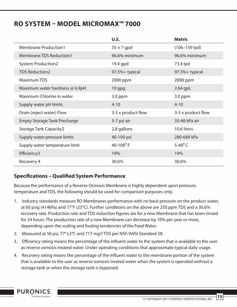
ro SYStem – moDeL mIcromaX™ 7000
U.S. metric
membrane production1 35 ± 7 gpd (106–159 lpd)
membrane tDs reduction1 96.6% minimum 96.6% minimum
system production2 19.4 gpd 73.4 lpd
tDs reduction2 97.5%+ typical 97.5%+ typical
maximum tDs 2000 ppm 2000 ppm
maximum water hardness @ 6.9ph 10 gpg 2.64 gpL
maximum Chlorine in water 3.0 ppm 3.0 ppm
supply water ph limits 4-10 4-10
Drain (reject water) Flow 3-5 x product flow 3-5 x product flow
empty storage tank precharge 5-7 psi air 35-48 kpa air
storage tank Capacity2 2.8 gallons 10.6 liters
supply water pressure limits 40-100 psi 280-689 kpa
supply water temperature limit 40-100⁰ F 5-40⁰ C
efficiency3 19% 19%
recovery 4 30.6% 30.6%
Specifications – Qualified System Performance
Because the performance of a reverse osmosis membrane is highly dependent upon pressure,temperature and tDs, the following should be used for comparison purposes only.
1. industry standards measure ro membranes performance with no back pressure on the product water,at 60 psig (414kpa) and 77°F (25°C). Further conditions on the above are 250 ppm tDs and a 30.6%recovery rate. production rate and tDs reduction figures are for a new membrane that has been rinsedfor 24 hours. the production rate of a new membrane can decrease by 10% per year or more,depending upon the scaling and fouling tendencies of the Feed Water.
2. measured at 50 psi, 77°±2°F, and 717 mg/l tDs per nsF/ansi standard 58.
3. efficiency rating means the percentage of the influent water to the system that is available to the useras reverse osmosis treated water. under operating conditions that approximate typical daily usage.
4. recovery rating means the percentage of the influent water to the membrane portion of the systemthat is available to the user as reverse osmosis treated water when the system is operated without astorage tank or when the storage tank is bypassed.
© Copyright 2011 puroniCs Water systems, inC.15
Non-potable Water Sources:
Do not attempt to use this product to make safe drinking water from non-potable water sources. Do not usethe system on microbiologically unsafe water, or water of unknown quality without adequate disinfectionbefore or after the system. this system is certified for cyst reduction and may be used on disinfected waterthat may contain filterable cysts.
arsenic reduction:
this system shall only be used for arsenic reduction on chlorinated water supplies containing detectableresidual free chlorine at the system inlet. Water systems using an inline chlorinator should provide a oneminute chlorine contact time before the reverse osmosis system.
Nitrate/Nitrite test Kit:
this system is acceptable for treatment of influent concentrations of no more than 27mg/L nitrate and3mg/L nitrite in combination measured as n. it is certified for nitrate/nitrite reduction only for water supplieswith a pressure of 280 kpa (40 psig) or greater. this system is supplied with a nitrate/nitrite test kit. productwater should be monitored periodically according to the instructions provided with the test kit.
Installations in the commonwealth of massachusetts:
the Commonwealth of massachusetts requires installation be performed by a licensed plumber and do notpermit the use of saddle valves. plumbing code 248--Cmr of the Commonwealth of massachusetts must befollowed in these cases.
Product Water testing:
the reverse osmosis system contains a replaceable membrane cartridge critical for the effective reductionof total dissolved solids (tDs).
replacement of the reverse osmosis membrane cartridge:
the reverse osmosis system contains a replaceable membrane cartridge critical to the efficiency of thesystem. membrane replacement is often based on your local water quality and usage. only replace thereverse osmosis membrane with a part approved for use in your reverse osmosis system.
© Copyright 2011 puroniCs Water systems, inC.16
SYStem maINteNaNce
easy change™ Prefilter/Postfilter
the pre-filter and post-filters are replaceable activated carbon cartridges located in stages 1 and 3. it isrecommended replacing these cartridges at least every 12 months (2,500 gallon capacity). you may need toreplace more often with high water usage or high sediment level. replacing these cartridges timely willprotect the ro membrane from high levels of chlorine and/or sediment. as these filters build up withsediment, you may notice slower water output.
easy change™ ro membrane cartridge
the ro cartridge is located in stage 2. this membrane is a tightly wound membrane which reduces thedissolved solids and organic matter. Cartridge life depends on ph and supply water hardness. higher phshortens membrane life by causing pin-hole leaks. if ph is higher than 8.0, cartridge life may be as short as6 months. if ph is under 7.5, cartridge life may last up to 3-5 years. When output water quality andproduction rate decrease, it is time to replace the membrane cartridge.
Flow rate and output are determined by 3 factors:1 incoming water temperature2 total dissolved solids (tDs) present in supply water3 incoming water pressure
Lower temperatures are directly proportional to slower flow rate. all membranes are tested at 77°F.incoming water temperature should not exceed 100°F. the ro Filter system should also not be installed in alocation susceptible to freezing.
the more tDs in the supply water, greater filter time is required. incoming tDs should not exceed 2000 ppm.
higher water pressure enables a higher flow rate. pressure must be above 40 psi for proper systemoperation. you may consider installing a permeate pump or booster pump if your pressure is below 40 psi.
© Copyright 2011 puroniCs Water systems, inC.17
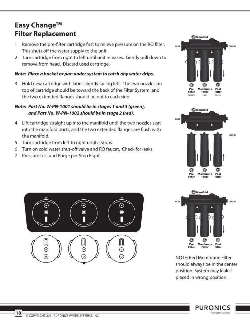
easy changetm
filter replacement1 remove the pre-filter cartridge first to relieve pressure on the ro filter.
this shuts off the water supply to the unit.2 turn cartridge from right to left until unit releases. gently pull down to
remove from head. Discard used cartridge.
Note: Place a bucket or pan under system to catch any water drips.
3 hold new cartridge with label slightly facing left. the two nozzles ontop of cartridge should be toward the back of the Filter system, andthe two extended flanges should be out to each side.
Note: Part No. W-PN-1001 should be in stages 1 and 3 (green), and Part No. W-PN-1002 should be in stage 2 (red).
4 Lift cartridge straight up into the manifold until the two nozzles seatinto the manifold ports, and the two extended flanges are flush withthe manifold.
5 turn cartridge from left to right until it stops.6 turn on cold water shut-off valve and ro faucet. Check for leaks. 7 pressure test and purge per step eight.
MembraneFilter(red)
PreFilter(green)
PostFilter(green)
Manifold
INLET OUTLET
MembraneFilter
PreFilter
PostFilter
Manifold
INLET
OUTLET
MembraneFilter
PreFilter
PostFilter
Manifold
INLET OUTLET
© Copyright 2011 puroniCs Water systems, inC.18
note: red membrane Filtershould always be in the centerposition. system may leak ifplaced in wrong position.
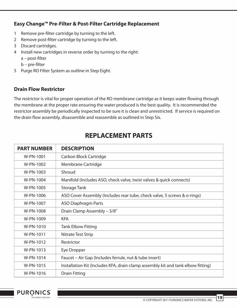
easy change™ Pre-filter & Post-filter cartridge replacement
1 remove pre-filter cartridge by turning to the left.2 remove post-filter cartridge by turning to the left.3 Discard cartridges.4 install new cartridges in reverse order by turning to the right:
a – post-filterb – pre-filter
5 purge ro Filter system as outline in step eight.
Drain flow restrictor
the restrictor is vital for proper operation of the ro membrane cartridge as it keeps water flowing throughthe membrane at the proper rate ensuring the water produced is the best quality. it is recommended therestrictor assembly be periodically inspected to be sure it is clean and unrestricted. if service is required onthe drain flow assembly, disassemble and reassemble as outlined in step six.
rePLacemeNt PartS
Part NUmBer DeScrIPtIoNW-pn-1001 Carbon Block Cartridge
W-pn-1002 membrane Cartridge
W-pn-1003 shroud
W-pn-1004 manifold (includes aso, check valve, twist valves & quick connects)
W-pn-1005 storage tank
W-pn-1006 aso Cover assembly (includes rear tube, check valve, 5 screws & o-rings)
W-pn-1007 aso Diaphragm parts
W-pn-1008 Drain Clamp assembly – 3/8”
W-pn-1009 KFa
W-pn-1010 tank elbow Fitting
W-pn-1011 nitrate test strip
W-pn-1012 restrictor
W-pn-1013 eye Dropper
W-pn-1014 Faucet – air gap (includes ferrule, nut & tube insert)
W-pn-1015 installation Kit (includes KFa, drain clamp assembly kit and tank elbow fitting)
W-pn-1016 Drain Fitting
© Copyright 2011 puroniCs Water systems, inC.19
Puronics Water Systems, Inc.5775 Las Positas RoadLivermore, CA 94551(800) 339-8780www.puronics.com
System Tested and Certified by the Water Quality Association (WQA) against NSF/ANSI Standard58 for the reduction of Cysts, Lead, Pentavalent Arsenic, Cadmium, Hexavalent Chromium,Trivalent Chromium, Selenium, Nitrites/Nitrates and Total Dissolved Solids (TDS) and againstNSF/ANSI Standard 42 for the aesthetic reduction of Chlorine Taste and Odor and Particulates.