Embed Size (px)
Citation preview

Micromotor of Less Than 1 mm3 Volume for In Vivo Medical Procedures
Brett Watson James FriendMonash University
Dept. of Mechanical EngineeringMicro/Nanophysics Research Laboratory
Clayton, Victoria, 3800, [email protected]
Leslie Yeo
Abstract
The body’s stress response to surgery has been citedas a primary cause of post-operative morbidity and hasprompted growth in minimally invasive surgical techniques.The future of such techniques lies in the use of in vivo proce-dures, but is currently limited by the availability of motorswith a volume of less than 1 mm3.
In response to this we present a piezoelectric ultra-sonic resonant micromotor with a volume of approximately0.75 mm3. The motor has a novel helically cut stator thatcouples axial and torsional resonant frequencies, excited bya lead zirconate titanate element 0.03 mm3 in volume. Themotor performance reaches a start-up torque of 47 nNm andno load angular velocity of 830 rad/s. This gives the motora power density of 18.4 kW/m3. This performance is on theorder necessary to propel a swimming microbot in small hu-man arteries.
1. Introduction
The body’s stress response to surgery has been cited asa primary cause of post-operative morbidity and compli-cations during post-operative care [14], which has led re-searchers to search for methods to reduce the stress causedby major surgical traumas [14],[3]. A successful methodhas been the use of minimally invasive surgery (MIS),which has been shown to reduce the stress caused by majorprocedures, and has led to new techniques in every special-ity of surgical medicine [6].
Currently, catheters and endoscopes are the instrumentsmost widely used during MIS. The instruments are intro-duced to the body by the surgeon, and require a high levelof skill to control [8]. Despite the advances made and suc-cesses achieved with these instruments, in many circum-stances MIS is not considered to be better than traditional
cut and sew techniques. In such circumstances, current min-imally invasive techniques are seen to lead to a loss of dex-terity, feel and a compromised view of the procedure, evenin the most complex and expensive systems [9].
To rectify this, research is being carried out on systemsthat will permit procedures to be conducted on the micro-scale using remotely operated micro-robots (microbots).Medical procedures using these devices will require onlya small, or possibly no, incision in the body and will per-mit in vivo techniques to be used. The ultimate aim ofsuch in vivo microbots is to carry out complex tasks includ-ing observation, sampling, drug delivery and surgical pro-cedures within the cardiovascular, digestive and lymphaticsystems [2].
To work effectively inside the human body, these mi-crobots must be sub-millimetre in size, be able to moverapidly and accurately and conduct procedures with lowpower consumption. One of the major obstacles to real-ising such designs is the availability of a practical micro-motor with a volume of less than 1 mm3 to act as a drivesystem. Numerous methods have been proposed to realisethe goal of a motor with a volume of less than 1 mm3, themost successful of which include electrostatic [20], elec-tromagnetic [12] and piezoelectric ultrasonic resonant [13]designs. If we examine the driving force used as the basisof design of these motors (electrostatic force, electromag-netic force and the converse piezoelectric effect), we candemonstrate that piezoelectric ultrasonic resonant motorshave favourable scaling characteristics [18], high torque lowspeed outputs and simple construction, leading to the bestpotential for use as a practical micro-motor.
Some small scale piezoelectric ultrasonic resonant mo-tors have been produced [13, 19], but due to a range ofshortcomings common to current piezoelectric ultrasonicresonant designs, a rotational motor with a volume of sig-nificantly less than 1 mm3 has not been achieved. Suchshortcomings include the fragility of the motor due to thestator being fabricated from a piezoelectric ceramic, the in-
2009 Third International Conference on Quantum, Nano and Micro Technologies
978-0-7695-3524-1/09 $25.00 © 2009 IEEE
DOI 10.1109/ICQNM.2009.14
81
Authorized licensed use limited to: Monash University. Downloaded on September 8, 2009 at 23:46 from IEEE Xplore. Restrictions apply.
creased motor complexity arising from requiring multipleelectrical input signals and difficulties in fabrication. Witha novel stator design, we have been able to simplify cur-rent piezoelectric ultrasonic resonant actuators, overcomingmany of these shortcomings.
2. Basis of Operation
Piezoelectric ultrasonic resonant motors make use of thedisplacement associated with the excitation of a resonantmode or coupled modes within the motor stator. The care-fully selected modes result in an elliptical cyclic motion atthe point of contact between the stator and rotor (the sta-tor tip). In conjunction with a friction coupling [16], thisensures a larger angular displacement is imparted on therotor during one half of the vibration cycle, resulting in anet angular displacement after a complete cycle. The reso-nant mode(s) of the stator are excited by a harmonic load-ing from a piezoelectric element, arising from the conversepiezoelectric effect.
Research to date has focussed on the use of coupled or-thogonal bending modes to elicit elliptical motion at thestator tip [13, 19]. In general, bending modes are excitedthrough the application of two electrical driving signals to astator fabricated from a piezoelectric material. This resultsin the shortcomings outlined in Section 1.
For the motor design detailed in this paper, we use cou-pled axial and torsional resonant modes in place of the or-thogonal bending modes. The coupled axial and torsionalmodes are to be excited by a lead zirconate titanate (PZT)piezoelectric element external to the stator. Fig. 1 demon-strates how the combination of the coupled mode shapesand the phase difference between the axial and torsionalcomponents, produces the desired elliptical motion at thestator tip. This methodology allows us to simplify the over-all motor which has the following benefits:
• Reduced complexity – By coupling the axial and tor-sional resonant modes through the stator geometry, only onedriving signal is required to run the motor.
• More robust – The piezoelectric element in the designis not part of the stator. This reduce the proportion of themotor that is fabricated from a piezoelectric ceramic, im-proving the robustness of the design.
• Improved fabrication – The piezoelectric element re-quired is only a simple rectangular prism, making for eas-ier fabrication. Other parts are fabricated by laser micro-machining, a method common in micro-stent and surgicalimplant fabrication.
t=0 t=T/4 t=T/2 t=T
Elliptical path of the stator tip
t=3T/4
Figure 1. The axial and torsional resonantmodes are coupled through the introductionof helical cuts to the stator. The coupledmodes result in the elliptical stator tip motionas shown for one complete vibration cycle.Note: t is time and T is period.
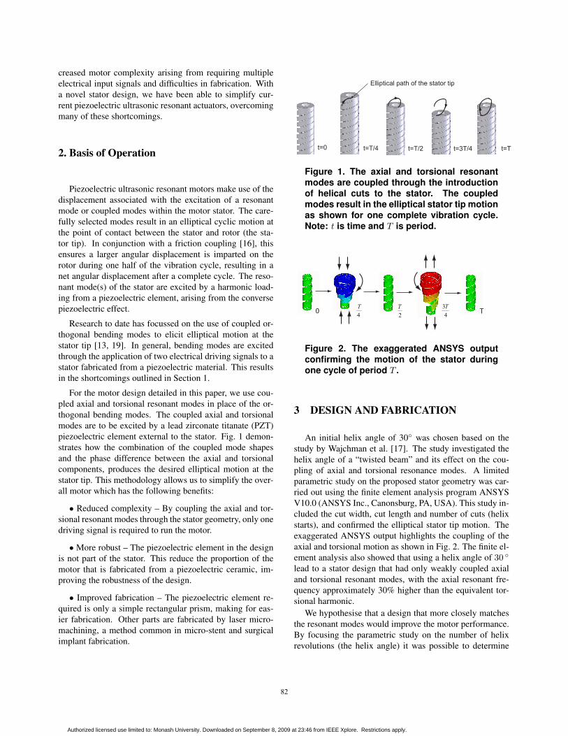
0
4T
2T
43T
T
Figure 2. The exaggerated ANSYS outputconfirming the motion of the stator duringone cycle of period T .
3 DESIGN AND FABRICATION
An initial helix angle of 30 was chosen based on thestudy by Wajchman et al. [17]. The study investigated thehelix angle of a “twisted beam” and its effect on the cou-pling of axial and torsional resonance modes. A limitedparametric study on the proposed stator geometry was car-ried out using the finite element analysis program ANSYSV10.0 (ANSYS Inc., Canonsburg, PA, USA). This study in-cluded the cut width, cut length and number of cuts (helixstarts), and confirmed the elliptical stator tip motion. Theexaggerated ANSYS output highlights the coupling of theaxial and torsional motion as shown in Fig. 2. The finite el-ement analysis also showed that using a helix angle of 30
lead to a stator design that had only weakly coupled axialand torsional resonant modes, with the axial resonant fre-quency approximately 30% higher than the equivalent tor-sional harmonic.
We hypothesise that a design that more closely matchesthe resonant modes would improve the motor performance.By focusing the parametric study on the number of helixrevolutions (the helix angle) it was possible to determine
82
Authorized licensed use limited to: Monash University. Downloaded on September 8, 2009 at 23:46 from IEEE Xplore. Restrictions apply.

0
1
2
3
4
5
6
0 200 400 600 800
Resonant Frequency (kHz)
Num
ber o
f Hel
ix R
evol
utio
ns
1st Torsional Mode 1st Axial Mode2nd Torsional Mode 2nd Axial Mode3rd Torsional Mode 3rd Axial Mode
Figure 3. The axial and torsional resonantfrequencies for the first three harmonics fora stator with three helical cuts and vary-ing helix revolutions. The intersection ofthe curves identifies a stator geometry thatclosely matches the axial and torsional reso-nances.
stator geometries that more closely matched the axial andtorsional resonant frequencies. Fig 3 is an extract from thisstudy, demonstrating how the axial and torsional resonantfrequencies vary with the number of revolutions in the heli-cal cut. The intersection of the curves identifies a geometrythat closely matches the torsional and axial resonant fre-quencies.
From the study, a stator geometry using 3.5 helix revo-lutions and three identical helical cuts was selected; Fig. 4details the geometry dimensions. The motor prototype wasfabricated from a 304 stainless steel tube with the helicalcuts laser cut at equal circumferential spacing (fabricatedby Laser Micromachining Solutions, Macquarie University,NSW, Aust.). A magnetic preload was used as part of thefriction coupling, and was measured to be 53 µN. The reso-nant modes were excited by a 0.25 mm x 0.25 mm x 0.5 mmlead zirconate titanate (PZT) element (C203, Fuji Ceramics,Tokyo, Japan). The motor setup is shown in Fig. 5. The mo-tor was trialled for each of the finite element model derivedaxial/torsional coupled resonant frequencies using a band-width of 5% to allow for manufacturing tolerances. Themotor demonstrated bi-directional operation with clockwiserotation at the third harmonic, 732 kHz and counterclock-wise rotation at the second harmonic, 526 kHz.
To confirm the study results, the ANSYS model was val-idated using a modified version of the method outlined byFriend et al. [4]. To experimentally determine the reso-nant modes, this method compares laser doppler vibrom-eter (LDV) measured displacement spectra at six points onthe stator tip. With sensible application, this method allowsthe resonant modes to be classified directly from these spec-
Object Dimension (μm) Base Tube
Inside Diameter 200 Outside Diameter 241
Length 985 Helical Cut
Width 28 Pitch 440
Length 880
Figure 4. The stator geometry chosen toclosely match the axial and torsional reso-nant frequencies while ensuring the overallvolume remained less than 0.25 mm3.
Solid
Wor
ks E
duca
tiona
l Lic
ense
Inst
ruct
iona
l Use
Onl
y
Ø0.4mm magnet
Ø0.5mm stainlesssteel ball
Helically cutstator
PZT element
Ø0.4mm magnet
Figure 5. The motor set-up included the heli-cally cut 240 µm diameter stator, a 0.5 mm di-ameter stainless ball as the rotor, a 0.25 mmx 0.25 mm x 0.5 mm PZT element, and two0.4 mm diameter magnets to provide preload,resulting in a motor with a volume of lessthan 1 mm3.
tra. These results are then compared with those produced byANSYS. Fig. 6 shows the recorded spectra and comparableANSYS results for a stator with five helix rotations and twocuts.
4 Results
Motor performance was determined using the methodby Nakamura et al. [15]. Rotor motion was recorded us-ing a laser doppler velocimeter (Canon LV-20Z, Kiyohara-Kogyodanchi, Utsunomiya-shi, Tochigi-ken, Japan). Amaximum clockwise angular velocity of 830 rad/s(7,925 rpm) was recorded at an input of 20 Vp−p and732 kHz. Based on the curve in Fig. 7, the average clock-
83
Authorized licensed use limited to: Monash University. Downloaded on September 8, 2009 at 23:46 from IEEE Xplore. Restrictions apply.

0
0.25
0.5
0.75
1
0 250 500 750 1000
Frequency (kHz)
Net
Dis
plac
emen
t (nm
) 4094
99
170
288336
36
106117
178 287 345
YZ
YY
XY YXXX
XZ
Y
XZ
YYXY
XXYXYZ
XZ
(b)
(a)
(c)
Figure 6. Finite element analysis validationthrough the comparison of stator resonantfrequencies obtained from (a) LDV recordeddisplacement spectra and (b) ANSYS calcu-lated frequencies using the measurement po-sitions detailed in (c) for a stator with five he-lix revolutions and two helical cuts.
wise start-up torque was 47 nNm with a peak of 51 nNm anda minimum of 39.8 nNm. The fitted exponential curve is de-rived from the standard curve for a piezoelectric ultrasonicmotor [15]. The average braking torque was calculated tobe 17.8 nNm. A maximum counterclockwise angular ve-locity of 1600 rad/s (15,280 rpm) at 32.1 Vp-p and 526 kHzwas recorded; however, the inconsistent nature of the op-eration prevented the measurement of the complete motorperformance.
5 Discussion
The reported motor demonstrated bidirectional oper-ation, however, counterclockwise motion was unreliablewhen compared with clockwise operation. When makinguse of two sequential torsional modes to obtain bidirectionalmotion, as is the case here, we expect the clockwise direc-tion to be superior due to the tendency of the stator to “un-curl” in that direction during extension of the stator. This isa result of the helical geometries used in the design and willbenefit the performance of the motor through an increasedtangential displacement for each cycle. By matching the
−=Ω
−00745.01789
t
e
−=Ω
02.01789 t
7890 =Ω rad/s
0
250
500
750
1000
0 50 100 150
Time (ms)
Angu
lar V
eloc
ity (r
ad/s
)
Figure 7. The angular velocity vs. time curve,as derived by the method in [15], for an ap-plied step voltage of 20 Vp−p, preload of 53 µNand an operating frequency of 732 kHz. Thefitted curve is average obtained across allruns as recorded by the points.
desired operational frequencies of the motor to the resonantmode of the piezoelectric element we will ensure the max-imum motor performance, which will enable a consistentbi-directional operation to be achieved. Further researchinto the exact geometry mechanisms driving the changes inthe axial/torsional resonant frequencies is required to realisethe successful matching of piezoelectric and stator resonantmodes.
We now give an example of how such a motor may beused for in vivo medical procedures. We examine a “swim-ming microbot” that uses an E.coli-like flagella as a meansof propulsion. Such microbots have been highlighted ashaving great potential for use in in vivo medical proceduresdue to the low Reynolds number propulsion system [1]. Weuse Higdon’s model for flagellar propulsion [11], to deter-mine the average power required for swimming in small hu-man arteries:
P = 6πµAU2η−10 K
where blood has a viscosity of approximately µ =0.004 Pa-s [7]; A, is the radius of the swimming microbot which weassume to be approximately the size of the motor, 150 µm,K is the Stokes’ law correction for a prolate spheroid,2.7 [10], and η−1
0 = 200 from Higdon’s results. For use-ful operation, the device should at least swim as fast as theblood flow, in the case of the right central retinal artery—a suitable example of a location both difficult to reach byother means and presumably one where this device wouldbe used—U ≈ 6.0 cm/s [5], giving a required input powerof 24 µW.
The average power output of the motor is approximately
84
Authorized licensed use limited to: Monash University. Downloaded on September 8, 2009 at 23:46 from IEEE Xplore. Restrictions apply.
(φmaxTmax)/4 = 9.75 µW, where φmax is the maximumclockwise velocity and Tmax is the average start-up torque.Although this power is smaller than what is required, it ispotentially not out of reach of such a device.
6 Conclusion and Future Work
We have demonstrated a motor with potential applica-tions in in vivo medical procedures. The novel stator designcoupling axial and torsional resonant modes simplifies cur-rent piezoelectric ultrasonic resonant designs and results ina motor volume of less than 1 mm3. The motor has a peaktorque of 51 nNm and a maximum rotational velocity inexcess of 15,000 rpm. The motor performance was theoret-ically shown to be significant enough to propel a swimmingmicrobot in the human body.
Future work on this design will focus on two areas; im-proved performance and reliability, and applications. To im-prove the performance of the motor, further research will beconducted to develop an analytical model of the motor. Thismodel will act as a design tool to allow the axial and tor-sional stator resonances to be more closely matched to thethickness resonance of the piezoelectric element. This is ex-pected to improve the motor performce and produce stablebi-directional operation. Research will also be conductedinto creating a more reliable and compact rotor/preload ar-rangement, ensuring the motor is ready to be used in a rangeof applications. Of a main interest in application trials willbe to trial the motor in conjucntion with a flagella propul-sion system, confirming the throetical prediction outlined inSection 5.
References
[1] B. Behkam and M. Sitti. Design methodology forbiomimetic propulsion of miniature swimming robots.ASME Journal of Dynamic Systems and Measurement Con-trol, 128:36–43, 2006.
[2] F. Cepolina, B. Challacombe, and R. Michelini. Trends inrobotic surgery. Journal of Endourology, 19(8):940–951,2005.
[3] J. Desborough. The stress response to trauma and surgery.British Journal of Anaesthesia, 85(1):109–117, 2000.
[4] J. Friend, K. Nakamura, and S. Ueha. A torsional transducerthrough in-plane shearing of paired planar piezoelectric el-ements. IEEE Transactions on Ultrasonics, Ferroelectrics,and Frequency Control, 51(7):870–877, 2004.
[5] G. Fuchsjger-Mayrl, K. Polak, A. Luksch, E. Polska,G. Dorner, G. Rainer, H.-G. Eichler, and L. Schmetterer.Retinal blood flow and systemic blood pressure in healthyyoung subjects. Graefe’s Archive for Clinical and Experi-mental Ophthalmology, 239(9):673–677, 2001.
[6] K. Fuschs. Minimally invasive surgery. Endoscopy, 34:154–159, 2002.
[7] J. Galduroza, H. Antunesb, and R. Santos. Gender- and age-related variations in blood viscosity in normal volunteers: Astudy of the effects of extract of allium sativum and ginkgobiloba. Phytomedicine, 14:447–451, 2007.
[8] Y. Haga and M. Esashi. Biomedical microsystems for min-imally invasive diagnosis and treatment. Proceedings of theIEEE, 92(1):98–114, 2004.
[9] E. Hanly and M. Talamini. Robotic abdominal surgery. TheAmerican Journal of Surgery, 188:19S–26S, October 2004.
[10] J. Happel and H.Brenner. Low Reynolds Number Hydrody-namics. Prentice Hall, Englewood Cliffs, NJ, 1965.
[11] J. Higdon. The hydrodynamics of flagellar propulsion: He-lical waves. Journal of Fluid Mechanics, 94:331–351, 1978.
[12] K. Hori, T. Miyagawa, and K. Ito. Development of ultra-small sized servo actuator with brushless DC motor, plan-etary gear drive and optical rotary encoder. InternationalJournal of the Japan Society for Precision Engineering,31:1–5, 1997.
[13] T. Kanda, A. Makino, L. Suzumori, T. Morita, and M. Kuro-sawa. A cylindrical micro ultrasonic motor using a micro-machined bulk piezoelectric transducer. In IEEE Ultrason-ics Symposium, 2004.
[14] H. Kehlet and D. W. Wilmore. Fast-track surgery. BritishJournal of Surgery, 92(1):3–4, 2005.
[15] M. Nakamura, K.and Kurosawa and S. Ueha. Characteristicsof a hybrid transducer-type ultrasonic motor. IEEE Transac-tions on Ultrasonics, Ferroelectrics, and Frequency Control,38(3):6, 1991.
[16] K. Uchino. Piezoelectric ultrasonic motors: Overview.Smart Material Structures, 7:273–285, 1998.
[17] D. Wajchman, D. Liu, J. Friend, and L. Yeo. An ultrasonicpiezoelectric motor utilising a non-circular cross sectionedtwisted beam. IEEE Transactions on Ultrasonics, Ferro-electrics and Frequency Control, 55(4):832–840, 2008.
[18] Z. Wang. Nanopiezotronics. Advanced Materials, 19:889–892, 2007.
[19] H. Zhang, S. Dong, S. Zhang, T. Wang, Z. Zhang, andL. Fan. Ultrasonic micro-motor using miniature piezoelec-tric tube with diameter of 1.0 mm. Ultrasonics, 44:e603–e606, 2006.
[20] W. Zhang, G. Meng, and H. Li. Electrostatic micromotorand its reliability. Microelectronics Reliability, 45:1230–1242, 2005.
85
Authorized licensed use limited to: Monash University. Downloaded on September 8, 2009 at 23:46 from IEEE Xplore. Restrictions apply.

![Dual-Fuel-Driven Bactericidal Micromotor · [21, 22]. Because of the environmentally friendly nature of the magnesium-based micromotor, it has been demon-strated that they have potentials](https://img.pdfslide.net/doc/110x75/5bdb866709d3f2bc1c8c0d17/dual-fuel-driven-bactericidal-micromotor-21-22-because-of-the-environmentally.jpg)