Embed Size (px)
Citation preview

Micropile Wall Supporting a Complex Environmental Excavation
Matthew Janes, M.E.Sc., P.Eng., Isherwood Associates
Abstract: Case 1 (non‐reticulated) micropiles are commonly used to stabilise earth for bearing
applications. They may also be effectively used as a shoring solution. In Victoria BC a complex
environmental clean‐up problem was solved using a capped, Case 1 micropile wall. The site was
bordered by a major thoroughfare with a buried high voltage power duct on the uphill side and a salmon
bearing stream within a municipal park on the downhill side. Mineral oil coolant had leaked from the
duct and contaminated the soils beneath the road way and were now leaching into the stream. BC
Hydro required a clean‐up of the embankment soils, a leachate collection system to capture pollutants
until an alternate power supply to the city could be completed (permitting de‐commissioning of the
leaking duct) and a cut off wall to prevent future contamination of the stream. The site was further
complicated by overhead power and communication lines within the construction footprint. Excavation
depths of up to 4.5 m were required (14.8 ft) to the planned contaminant depth, with the real risk of
chasing product deeper. A Case 1 micropile wall was installed within the narrow construction easement
between the duct and the overhead power lines. A double row of 8 m long vertical injection anchors
were installed on 400 mm c/c spacing. A single row of raked (1H:2V) micropiles were incorporated with
a reinforced concrete pile cap. Excavation of the micropile face to 4.5 m depth was easily conducted
with effective soil arching between the micropiles. The space between the micropiles allowed for free
flow of groundwater and leachate into a gravel and geotextile leachate collection system that was
constructed on the face of the micropile wall. Behind the leachate collection system a mechanically
stabilised earth embankment was installed with a ‘living wall façade’. A living wall façade incorporates
buried live roots and organics to form a living wall facing on the finished exposed face. The back side of
the mechanically stabilised earth structure, adjacent to the leachate collection system, was constructed
with a low strength concrete wall formed in 1 m lifts. The geogrid used in the mechanically stabilised
earth wall was anchored into the low strength concrete wall. This provided an impermeable wall behind
the leachate collection system, ensuring contaminants would not find their way to the stream and a
future shoring wall (in the opposite direction) for future removal of the BC Hydro duct, roadway and
contaminated soils beneath which is planned over the coming 2‐3 years.
Introduction
In Victoria, British Columbia, a complex environmental clean‐up problem was solved using a capped,
Case 1 micropile wall. The ravine site was bordered by a major thoroughfare with a buried 300 kV
power duct on the uphill side and a salmon bearing stream within a municipal park on the downhill side.
Mineral oil coolant had leaked from the duct contaminating the soils beneath the road way and were
now leaching into the stream. BC Hydro, the project owner, required a low impact clean‐up of the soils
and restoration of the lands to a state that was harmonious with the existing park environment. A
previous clean‐up using a shotcrete wall had failed to provide a final product that met with public
approval. BC Hydro was tasked with removal of the contaminated soils without disruption of the
roadway, the existing duct or the salmon bearing stream. This limited equipment choices, methods and
schedule.
The embankment clean up required removal of contaminated soils, installation of a leachate collection
system to capture pollutants until an alternative power supply to the city could be completed
(permitting de‐commissioning of the leaking duct) and a cut off wall to prevent future contamination of
the stream. The site was further complicated by overhead power and communication lines within the
construction footprint. Excavation depths of up to 4.5 m (14.8 ft) were required to reach the proven
base of the contaminant, with the real risk of chasing product deeper. Of particular importance to BC
Hydro was the restoration of the slope to a naturally vegetated state that would not be disturbed during
future remediation of the roadway and replacement of the duct.
The proposed design called for a Case 1 injection anchor micropile wall to be installed within the narrow
construction easement between the duct and the overhead power lines. Small installation equipment
was needed to prevent damage to the existing ravine and minimise impact. Following top down
excavation of the embankment, a drainage wall, impermeable wall and a mechanically stabilised earth
slope was planned. The façade of the mechanically stabilised earth wall was designed as a ‘living shoring
face’ or ‘living earth wall.’ This design was conducted by others, but is shown and referenced for its
remarkable success in meeting the owner’s objectives.
Geotechnical
In typical fashion for environmental sites, copious soils borings were conducted, all logged by a biologist,
with no regard to geotechnical information. The 34 borings did not include geotechnical tests for
strength, grain size distribution, water content or Atterberg limits. Soils consisted of granular and
roadway compacted fills to 1 m depth, overlying native soils of firm silts with some clay to a depth of 4.3
to 4.5 m. This formation is described as blocky and brown to grey, indicating weathering within the
upper layers. Beneath the silt lay soft grey clay through to the depth of glacial till at 12 or more meters
(40 ft.).
Past experience in the Victoria, BC area would indicate the upper silts are unsaturated and provide SPT
blow counts on the order of 10 to 17/300mm (12”). It was anticipated the lower grey clays would
provide the following properties: SPT blows of 6 to 8/300 mm, shear vanes strength of 25 to 30 kPa (4
psi) with remolded strength of 10 to 16 kPa (2 psi), Liquid limit 40+%, Plastic limit 16‐18% and water
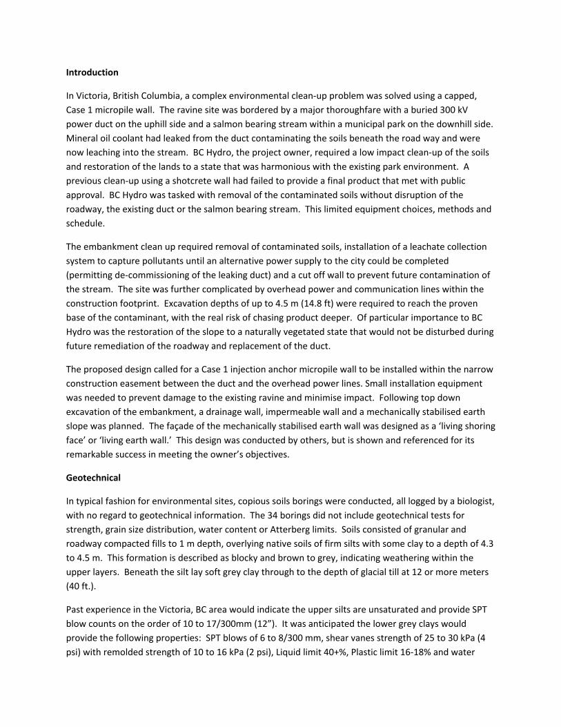
content 30+%. CPT results may indicate a Qt of 8 Bar. Typically the clays are slightly over consolidated
within the upper zones but within a few meters depth the OCR reduces to 1.0.
Figure 1. Geotechnical cross section from the Environmental Investigation
Design
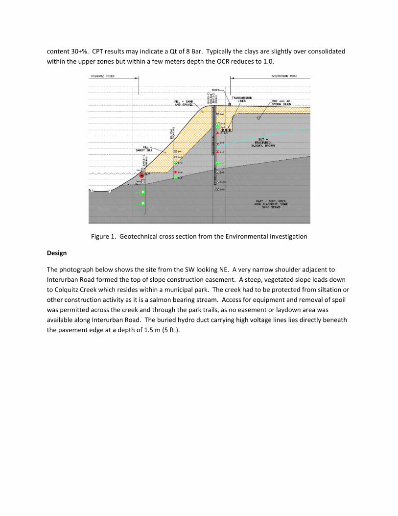
The photograph below shows the site from the SW looking NE. A very narrow shoulder adjacent to
Interurban Road formed the top of slope construction easement. A steep, vegetated slope leads down
to Colquitz Creek which resides within a municipal park. The creek had to be protected from siltation or
other construction activity as it is a salmon bearing stream. Access for equipment and removal of spoil
was permitted across the creek and through the park trails, as no easement or laydown area was
available along Interurban Road. The buried hydro duct carrying high voltage lines lies directly beneath
the pavement edge at a depth of 1.5 m (5 ft.).
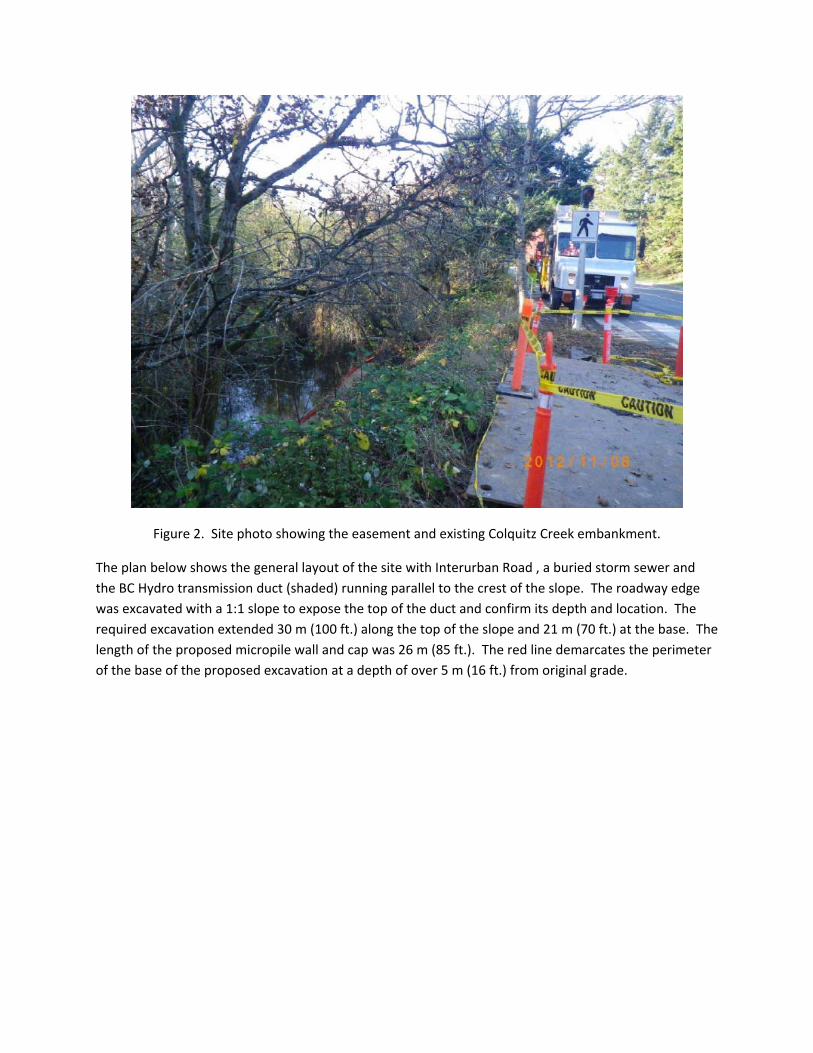
Figure 2. Site photo showing the easement and existing Colquitz Creek embankment.
The plan below shows the general layout of the site with Interurban Road , a buried storm sewer and
the BC Hydro transmission duct (shaded) running parallel to the crest of the slope. The roadway edge
was excavated with a 1:1 slope to expose the top of the duct and confirm its depth and location. The
required excavation extended 30 m (100 ft.) along the top of the slope and 21 m (70 ft.) at the base. The
length of the proposed micropile wall and cap was 26 m (85 ft.). The red line demarcates the perimeter
of the base of the proposed excavation at a depth of over 5 m (16 ft.) from original grade.
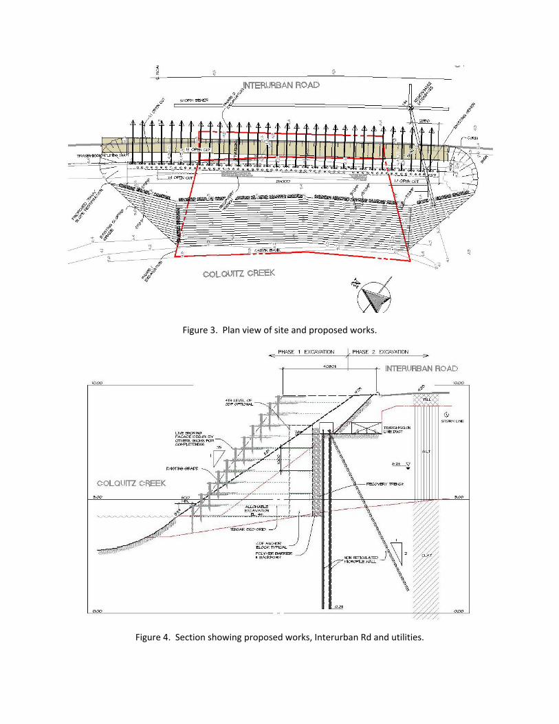
Figure 3. Plan view of site and proposed works.
Figure 4. Section showing proposed works, Interurban Rd and utilities.

The section above shows the overall easement with the original and final slopes, and the original 1:1
excavation which exposed the BC Hydro duct. This cut located the duct, permitted inspection and
ensured the contractor maintained the required 1000 mm (3 ft.) clearance between the edge of the duct
and micropile installation. The drawing shows the double row of vertical micropiles spaced 400 mm
(16”) c/c along the wall and 300 mm (12”) front to back. Every 800 mm (32”) a raked micropile, at
1H:2V, was drilled. The concrete cap encapsulated the micropile heads and created a truss structure.
The section shows the Control Density Fill (weak concrete or CDF) wall, leachate collection system
(recovery trench) and aquitard barrier. The CDF wall was tied into the geotextile of the reinforced earth
slope and façade. Note the phase 1 and phase 2 excavation zones. By creating more real estate (with a
steeper final slope) BC Hydro will later be able to excavate the roadway and existing high voltage duct
while relying upon the reinforced slope and CDF face as shoring with no disturbance to the restored
Colquitz Creek bank.
Finally the section shows the living wall façade which consists of a slope dressed with willow saplings
and other organic structures to generate a stable slope face which blends with the native foliage. The
façade is built up in layers and relies upon a deep root network to ensure a stabilised face as steep as 3V
to 1H.
As with all environmental projects the risk of excavation beyond the specified design depth was
probable. Thus the design assumed excavation to a meter below design depth (6.0 m or 20 ft.) without
need to augment the original wall design. This extended the excavation into the base soft grey clays.
The anticipated reduction in available passive toe resistance and low soil strength resulted in increased
pile lengths, moments and shears and drove the high density of micropiles.
The double row of micropiles may be designed classically using composite design in bending and shear,
assuming a low strength material acting in shear between the micropiles and the micropile steel acting
as compression and tension members. Essentially, the soil is are relied upon to keep the compression
and tension steel apart and the pile cap and bond length along the pile toes are relied upon to dissipate
the bending stresses.
FLAC Analysis
The proposed design was modeled using FLAC 3D. A 1 m (3 ft.) section of the wall was modeled
(emulating a 2D analysis), with individual micropile elements. This allows review of the assumption of
soil arching between the micropiles. In addition micropile axial load and bending moment is provided.
The FLAC predictions of micropile axial force and bending moment are provided in Figures 5 and 6
below.
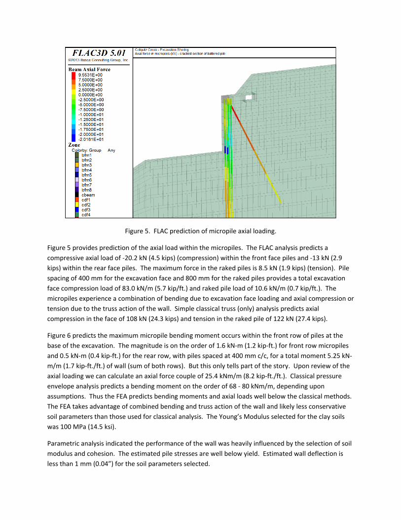
Figure 5. FLAC prediction of micropile axial loading.
Figure 5 provides prediction of the axial load within the micropiles. The FLAC analysis predicts a
compressive axial load of ‐20.2 kN (4.5 kips) (compression) within the front face piles and ‐13 kN (2.9
kips) within the rear face piles. The maximum force in the raked piles is 8.5 kN (1.9 kips) (tension). Pile
spacing of 400 mm for the excavation face and 800 mm for the raked piles provides a total excavation
face compression load of 83.0 kN/m (5.7 kip/ft.) and raked pile load of 10.6 kN/m (0.7 kip/ft.). The
micropiles experience a combination of bending due to excavation face loading and axial compression or
tension due to the truss action of the wall. Simple classical truss (only) analysis predicts axial
compression in the face of 108 kN (24.3 kips) and tension in the raked pile of 122 kN (27.4 kips).
Figure 6 predicts the maximum micropile bending moment occurs within the front row of piles at the
base of the excavation. The magnitude is on the order of 1.6 kN‐m (1.2 kip‐ft.) for front row micropiles
and 0.5 kN‐m (0.4 kip‐ft.) for the rear row, with piles spaced at 400 mm c/c, for a total moment 5.25 kN‐
m/m (1.7 kip‐ft./ft.) of wall (sum of both rows). But this only tells part of the story. Upon review of the
axial loading we can calculate an axial force couple of 25.4 kNm/m (8.2 kip‐ft./ft.). Classical pressure
envelope analysis predicts a bending moment on the order of 68 ‐ 80 kNm/m, depending upon
assumptions. Thus the FEA predicts bending moments and axial loads well below the classical methods.
The FEA takes advantage of combined bending and truss action of the wall and likely less conservative
soil parameters than those used for classical analysis. The Young’s Modulus selected for the clay soils
was 100 MPa (14.5 ksi).
Parametric analysis indicated the performance of the wall was heavily influenced by the selection of soil
modulus and cohesion. The estimated pile stresses are well below yield. Estimated wall deflection is
less than 1 mm (0.04”) for the soil parameters selected.
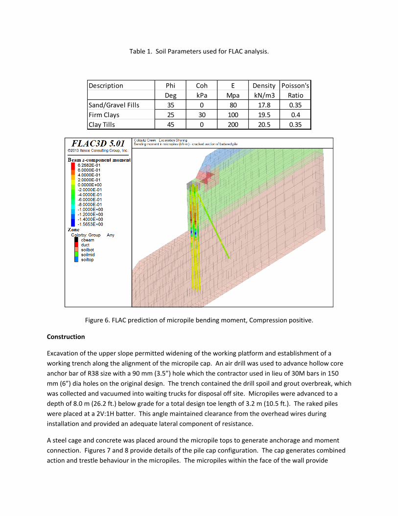
Table 1. Soil Parameters used for FLAC analysis.
Figure 6. FLAC prediction of micropile bending moment, Compression positive.
Construction
Excavation of the upper slope permitted widening of the working platform and establishment of a
working trench along the alignment of the micropile cap. An air drill was used to advance hollow core
anchor bar of R38 size with a 90 mm (3.5”) hole which the contractor used in lieu of 30M bars in 150
mm (6”) dia holes on the original design. The trench contained the drill spoil and grout overbreak, which
was collected and vacuumed into waiting trucks for disposal off site. Micropiles were advanced to a
depth of 8.0 m (26.2 ft.) below grade for a total design toe length of 3.2 m (10.5 ft.). The raked piles
were placed at a 2V:1H batter. This angle maintained clearance from the overhead wires during
installation and provided an adequate lateral component of resistance.
A steel cage and concrete was placed around the micropile tops to generate anchorage and moment
connection. Figures 7 and 8 provide details of the pile cap configuration. The cap generates combined
action and trestle behaviour in the micropiles. The micropiles within the face of the wall provide
Description Phi Coh E Density Poisson's
Deg kPa Mpa kN/m3 Ratio
Sand/Gravel Fills 35 0 80 17.8 0.35
Firm Clays 25 30 100 19.5 0.4
Clay Tills 45 0 200 20.5 0.35
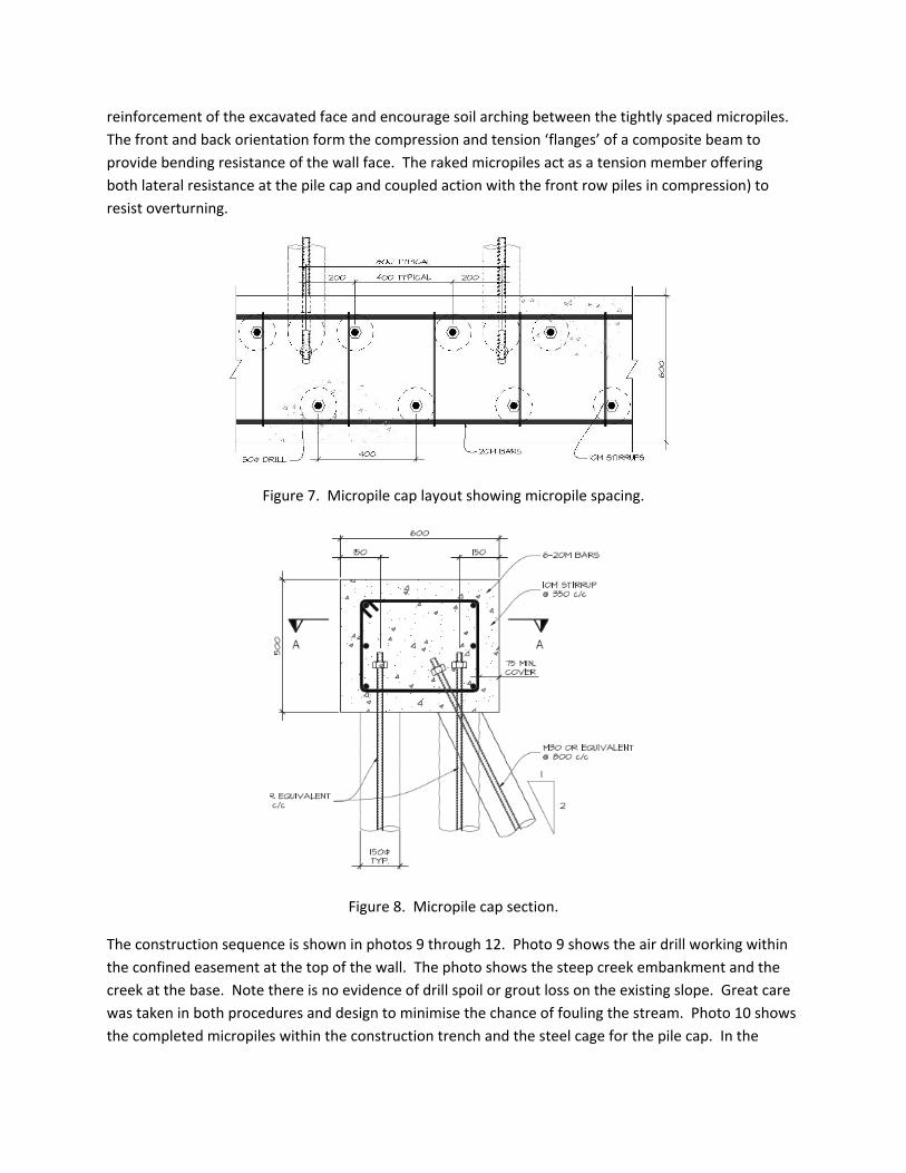
reinforcement of the excavated face and encourage soil arching between the tightly spaced micropiles.
The front and back orientation form the compression and tension ‘flanges’ of a composite beam to
provide bending resistance of the wall face. The raked micropiles act as a tension member offering
both lateral resistance at the pile cap and coupled action with the front row piles in compression) to
resist overturning.
Figure 7. Micropile cap layout showing micropile spacing.
Figure 8. Micropile cap section.
The construction sequence is shown in photos 9 through 12. Photo 9 shows the air drill working within
the confined easement at the top of the wall. The photo shows the steep creek embankment and the
creek at the base. Note there is no evidence of drill spoil or grout loss on the existing slope. Great care
was taken in both procedures and design to minimise the chance of fouling the stream. Photo 10 shows
the completed micropiles within the construction trench and the steel cage for the pile cap. In the
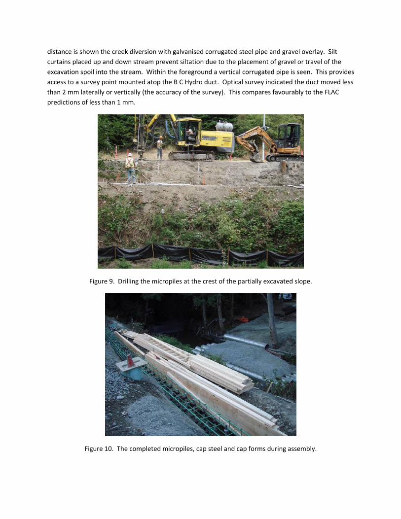
distance is shown the creek diversion with galvanised corrugated steel pipe and gravel overlay. Silt
curtains placed up and down stream prevent siltation due to the placement of gravel or travel of the
excavation spoil into the stream. Within the foreground a vertical corrugated pipe is seen. This provides
access to a survey point mounted atop the B C Hydro duct. Optical survey indicated the duct moved less
than 2 mm laterally or vertically (the accuracy of the survey). This compares favourably to the FLAC
predictions of less than 1 mm.
Figure 9. Drilling the micropiles at the crest of the partially excavated slope.
Figure 10. The completed micropiles, cap steel and cap forms during assembly.
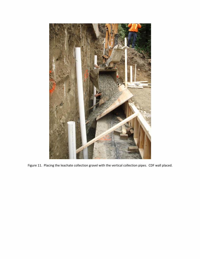
Figure 11. Placing the leachate collection gravel with the vertical collection pipes. CDF wall placed.
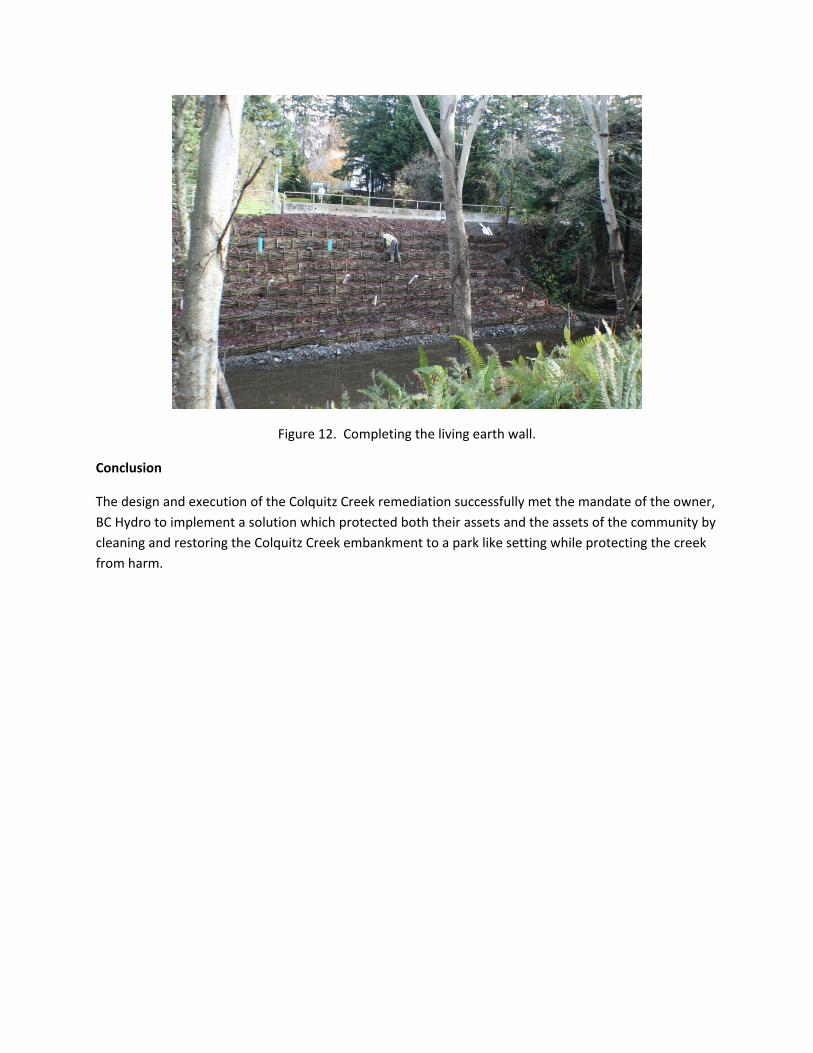
Figure 12. Completing the living earth wall.
Conclusion
The design and execution of the Colquitz Creek remediation successfully met the mandate of the owner,
BC Hydro to implement a solution which protected both their assets and the assets of the community by
cleaning and restoring the Colquitz Creek embankment to a park like setting while protecting the creek
from harm.