Embed Size (px)
Citation preview
Products Solutions Services
Operating InstructionsMicropilot FMR20HARTFree space radar
BA01578F/00/EN/01.1671325113

2 Endress+Hauser
1.
Order code:
Ext. ord. cd.:
Ser. no.:
www.endress.com/deviceviewer Endress+Hauser Operations App
XXXXXXXXXXXX
XXXXX-XXXXXX
XXX.XXXX.XX
Serial number
2.
3.
A0023555
Table of contents
Endress+Hauser 3
Table of contents
1 Document information . . . . . . . . . . . . . . 51.1 Symbols for certain types of information . . . . . . 51.2 Safety symbols . . . . . . . . . . . . . . . . . . . . . . . . . 51.3 Symbols in graphics . . . . . . . . . . . . . . . . . . . . . 5
2 Terms and abbreviations . . . . . . . . . . . . 6
3 Basic safety instructions . . . . . . . . . . . . 73.1 Requirements for personnel . . . . . . . . . . . . . . . 73.2 Designated use . . . . . . . . . . . . . . . . . . . . . . . . 73.3 Workplace safety . . . . . . . . . . . . . . . . . . . . . . . 83.4 Operational safety . . . . . . . . . . . . . . . . . . . . . . 83.5 Product safety . . . . . . . . . . . . . . . . . . . . . . . . . 8
3.5.1 CE mark . . . . . . . . . . . . . . . . . . . . . . . 8
4 Registered trademarks . . . . . . . . . . . . . . 8
5 Supplementary documentation . . . . . 105.1 Standard documentation . . . . . . . . . . . . . . . . 105.2 Supplementary documentation . . . . . . . . . . . . 105.3 Safety Instructions (XA) . . . . . . . . . . . . . . . . . 10
6 Product description . . . . . . . . . . . . . . . . 116.1 Product design . . . . . . . . . . . . . . . . . . . . . . . . 11
6.1.1 Micropilot FMR20 . . . . . . . . . . . . . . . 11
7 Incoming acceptance and productidentification . . . . . . . . . . . . . . . . . . . . . 12
7.1 Incoming acceptance . . . . . . . . . . . . . . . . . . . 127.2 Product identification . . . . . . . . . . . . . . . . . . . 13
8 Installation . . . . . . . . . . . . . . . . . . . . . . . 148.1 Installation conditions . . . . . . . . . . . . . . . . . . 14
8.1.1 Installation types . . . . . . . . . . . . . . . . 148.1.2 Nozzle installation . . . . . . . . . . . . . . . 148.1.3 Orientation . . . . . . . . . . . . . . . . . . . . 158.1.4 Alignment . . . . . . . . . . . . . . . . . . . . 158.1.5 Beam angle . . . . . . . . . . . . . . . . . . . . 168.1.6 Measurement in plastic vessels . . . . . 178.1.7 Weather protection cover . . . . . . . . . 178.1.8 Free-field measurement with
flooding protection tube . . . . . . . . . . 188.1.9 Installation with mounting bracket,
adjustable . . . . . . . . . . . . . . . . . . . . . 198.1.10 Cantilever installation, with pivot . . . . 198.1.11 Post-installation check . . . . . . . . . . . 19
9 Electrical connection . . . . . . . . . . . . . . 209.1 Cable assignment . . . . . . . . . . . . . . . . . . . . . . 209.2 Supply voltage . . . . . . . . . . . . . . . . . . . . . . . . 20
9.3 Connection . . . . . . . . . . . . . . . . . . . . . . . . . . 219.3.1 FMR20, 4 to 20 mA HART . . . . . . . . . 219.3.2 FMR20 with RIA15 . . . . . . . . . . . . . . 229.3.3 FMR20, RIA15 with installed HART
communication resistor module . . . . . 239.4 Post-connection check . . . . . . . . . . . . . . . . . . 23
10 Operability . . . . . . . . . . . . . . . . . . . . . . . . 2410.1 Operating concept . . . . . . . . . . . . . . . . . . . . . 2410.2 Via Bluetooth® wireless technology . . . . . . . . 2410.3 Via HART protocol . . . . . . . . . . . . . . . . . . . . . 24
11 Commissioning and operation . . . . . . 2511.1 Installation and function check . . . . . . . . . . . . 2511.2 Operation and settings via SmartBlue (app) . . 2511.3 System integration via HART protocol . . . . . . . 30
11.3.1 Overview of the Device DescriptionFiles (DD) . . . . . . . . . . . . . . . . . . . . . 30
11.3.2 Measured variables via HARTprotocol . . . . . . . . . . . . . . . . . . . . . . 30
11.4 Operation and settings via RIA15 . . . . . . . . . . 3111.4.1 Operating functions . . . . . . . . . . . . . . 3111.4.2 Operating modes . . . . . . . . . . . . . . . . 3211.4.3 Operating matrix . . . . . . . . . . . . . . . . 32
11.5 Configuring level measurement via operatingsoftware . . . . . . . . . . . . . . . . . . . . . . . . . . . . 3411.5.1 Displaying level value as % . . . . . . . . . 35
11.6 Configuring Flow measurement via operatingsoftware . . . . . . . . . . . . . . . . . . . . . . . . . . . . 3611.6.1 Installation conditions for Flow
measurement . . . . . . . . . . . . . . . . . . 3611.6.2 Configuring Flow measurement . . . . . 36
11.7 Data access - Security . . . . . . . . . . . . . . . . . . . 3911.7.1 Software locking via access code in
FieldCare / DeviceCare . . . . . . . . . . . . 3911.7.2 Unlocking via FieldCare /
DeviceCare . . . . . . . . . . . . . . . . . . . . 3911.7.3 Software locking via access code in
SmartBlue . . . . . . . . . . . . . . . . . . . . . 3911.7.4 Unlocking via SmartBlue . . . . . . . . . . 3911.7.5 Bluetooth® wireless technology . . . . . 3911.7.6 Locking RIA15 . . . . . . . . . . . . . . . . . 40
12 Diagnostics and troubleshooting . . . 4112.1 General trouble shooting . . . . . . . . . . . . . . . . 4112.2 General errors . . . . . . . . . . . . . . . . . . . . . . . . 4112.3 Diagnostic event . . . . . . . . . . . . . . . . . . . . . . 42
12.3.1 Diagnostic event in the operatingtool . . . . . . . . . . . . . . . . . . . . . . . . . . 42
12.3.2 Diagnostic event in the RIA15 . . . . . . 4212.4 List of diagnostic events . . . . . . . . . . . . . . . . . 4212.5 Overview of information events . . . . . . . . . . . 43

Table of contents
4 Endress+Hauser
13 Maintenance . . . . . . . . . . . . . . . . . . . . . . 4313.1 Exterior cleaning . . . . . . . . . . . . . . . . . . . . . . 4313.2 Seals . . . . . . . . . . . . . . . . . . . . . . . . . . . . . . . 43
14 Repair . . . . . . . . . . . . . . . . . . . . . . . . . . . . 4414.1 General notes . . . . . . . . . . . . . . . . . . . . . . . . 44
14.1.1 Repair concept . . . . . . . . . . . . . . . . . 4414.1.2 Replacing a device . . . . . . . . . . . . . . . 4414.1.3 Return . . . . . . . . . . . . . . . . . . . . . . . 4414.1.4 Disposal . . . . . . . . . . . . . . . . . . . . . . 44
15 Accessories . . . . . . . . . . . . . . . . . . . . . . . 4515.1 Overview . . . . . . . . . . . . . . . . . . . . . . . . . . . . 45
16 Operating menu . . . . . . . . . . . . . . . . . . . 5016.1 Overview operating menue (SmartBlue) . . . . . 5016.2 Overview of operating menu (FieldCare /
DeviceCare) . . . . . . . . . . . . . . . . . . . . . . . . . . 5416.3 "Setup" menu . . . . . . . . . . . . . . . . . . . . . . . . . 58
16.3.1 "Advanced setup" submenu . . . . . . . . . 6116.3.2 "Communication" submenu . . . . . . . . . 71
16.4 "Diagnostics" submenu . . . . . . . . . . . . . . . . . . 7516.4.1 "Device information" submenu . . . . . . 7716.4.2 "Simulation" submenu . . . . . . . . . . . . 79
Index . . . . . . . . . . . . . . . . . . . . . . . . . . . . . . . . . . 80

Micropilot FMR20 HART Document information
Endress+Hauser 5
1 Document information
1.1 Symbols for certain types of information
Symbol Meaning
PermittedProcedures, processes or actions that are permitted.
PreferredProcedures, processes or actions that are preferred.
ForbiddenProcedures, processes or actions that are forbidden.
TipIndicates additional information.
Reference to documentation
Reference to page
Reference to graphic
, …, Series of steps
Result of a step
Help in the event of a problem
Visual inspection
1.2 Safety symbols
Symbol Meaning
DANGER
DANGER!This symbol alerts you to a dangerous situation. Failure to avoid this situation willresult in serious or fatal injury.
WARNING
WARNING!This symbol alerts you to a dangerous situation. Failure to avoid this situation canresult in serious or fatal injury.
CAUTION
CAUTION!This symbol alerts you to a dangerous situation. Failure to avoid this situation canresult in minor or medium injury.
NOTICE
NOTE!This symbol contains information on procedures and other facts which do not result inpersonal injury.
1.3 Symbols in graphics
Symbol Meaning
1, 2, 3 ... Item numbers
, …, Series of steps
A, B, C, ... Views
A-A, B-B, C-C, ... Sections

Terms and abbreviations Micropilot FMR20 HART
6 Endress+Hauser
Symbol Meaning
-Hazardous areaIndicates a hazardous area.
.Safe area (non-hazardous area)Indicates the non-hazardous area.
2 Terms and abbreviationsTerm/abbreviation Explanation
BA Document type "Operating Instructions"
KA Document type "Brief Operating Instructions"
TI Technical Information
SD Document type "Special Documentation"
XA Document type "Safety Instructions"
PN Nominal pressure
MWP Maximum Working PressureThe MWP can also be found on the nameplate.
ToF Time of Flight
FieldCare Scalable software tool for device configuration and integrated plant asset managementsolutions
DeviceCare Universal configuration software for Endress+Hauser HART, PROFIBUS, FOUNDATIONFieldbus and Ethernet field devices
DTM Device Type Manager
DD Device Description for HART communication protocol
DK Relative dielectric constant εr
Operating tool The term "operating tool" is used in place of the following operating software:• SmartBlue (app), for operation using an Android or iOS smartphone or tablet.• FieldCare / DeviceCare, for operation via HART communication and PC
BD Blocking Distance; no signals are analyzed within the BD.
Micropilot FMR20 HART Basic safety instructions
Endress+Hauser 7
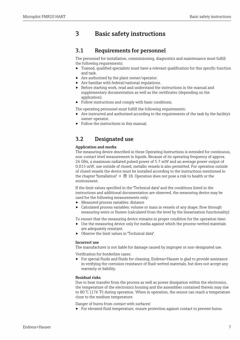
3 Basic safety instructions
3.1 Requirements for personnelThe personnel for installation, commissioning, diagnostics and maintenance must fulfillthe following requirements:‣ Trained, qualified specialists must have a relevant qualification for this specific function
and task.‣ Are authorized by the plant owner/operator.‣ Are familiar with federal/national regulations.‣ Before starting work, read and understand the instructions in the manual and
supplementary documentation as well as the certificates (depending on theapplication).
‣ Follow instructions and comply with basic conditions.
The operating personnel must fulfill the following requirements:‣ Are instructed and authorized according to the requirements of the task by the facility's
owner-operator.‣ Follow the instructions in this manual.
3.2 Designated useApplication and mediaThe measuring device described in these Operating Instructions is intended for continuous,non-contact level measurement in liquids. Because of its operating frequency of approx.26 GHz, a maximum radiated pulsed power of 5.7 mW and an average power output of0.015 mW, use outside of closed, metallic vessels is also permitted. For operation outsideof closed vessels the device must be installed according to the instructions mentioned inthe chapter "Installation" → 18. Operation does not pose a risk to health or theenvironment.
If the limit values specified in the "Technical data" and the conditions listed in theinstructions and additional documentation are observed, the measuring device may beused for the following measurements only:‣ Measured process variables: distance‣ Calculated process variables: volume or mass in vessels of any shape; flow through
measuring weirs or flumes (calculated from the level by the linearization functionality)
To ensure that the measuring device remains in proper condition for the operation time:‣ Use the measuring device only for media against which the process-wetted materials
are adequately resistant.‣ Observe the limit values in "Technical data".
Incorrect useThe manufacturer is not liable for damage caused by improper or non-designated use.
Verification for borderline cases:‣ For special fluids and fluids for cleaning, Endress+Hauser is glad to provide assistance
in verifying the corrosion resistance of fluid-wetted materials, but does not accept anywarranty or liability.
Residual risksDue to heat transfer from the process as well as power dissipation within the electronics,the temperature of the electronics housing and the assemblies contained therein may riseto 80 °C (176 °F) during operation. When in operation, the sensor can reach a temperatureclose to the medium temperature.
Danger of burns from contact with surfaces!‣ For elevated fluid temperature, ensure protection against contact to prevent burns.
Registered trademarks Micropilot FMR20 HART
8 Endress+Hauser
3.3 Workplace safetyFor work on and with the device:‣ Wear the required personal protective equipment according to federal/national
regulations.
3.4 Operational safetyRisk of injury.‣ Operate the device in proper technical condition and fail-safe condition only.‣ The operator is responsible for interference-free operation of the device.
Conversions to the deviceUnauthorized modifications to the device are not permitted and can lead to unforeseeabledangers.‣ If, despite this, modifications are required, consult with the manufacturer.
RepairTo ensure continued operational safety and reliability,‣ Carry out repairs on the device only if they are expressly permitted.‣ Observe federal/national regulations pertaining to repair of an electrical device.‣ Use original spare parts and accessories from the manufacturer only.
Hazardous areaTo eliminate a danger for persons or for the facility when the device is used in thehazardous area (e.g. explosion protection, pressure vessel safety):‣ Based on the nameplate, check whether the ordered device is permitted for the
intended use in the hazardous area.‣ Observe the specifications in the separate supplementary documentation that is an
integral part of these Instructions.
3.5 Product safetyThis measuring device is designed in accordance with good engineering practice to meetstate-of-the-art safety requirements, has been tested, and left the factory in a condition inwhich it is safe to operate. It meets general safety standards and legal requirements.
3.5.1 CE markThe measuring system meets the legal requirements of the applicable EC guidelines. Theseare listed in the corresponding EC Declaration of Conformity together with the standardsapplied.
Endress+Hauser confirms successful testing of the device by affixing to it the CE mark.
4 Registered trademarks
Registered trademark of the FieldComm Group, Austin, USA
The Bluetooth® word mark and logos are registered trademarks owned by the BluetoothSIG, Inc. and any use of such marks by Endress+Hauser is under license. Other trademarksand trade names are those of their respective owners.”

Micropilot FMR20 HART Registered trademarks
Endress+Hauser 9
Apple®Apple, the Apple logo, iPhone, and iPod touch are trademarks of Apple Inc., registered inthe U.S. and other countries. App Store is a service mark of Apple Inc.
Android®Android, Google Play and the Google Play logo are trademarks of Google Inc.

Supplementary documentation Micropilot FMR20 HART
10 Endress+Hauser
5 Supplementary documentationThe following document types are available in the Download Area of the Endress+HauserInternet site: www.endress.com → Download:
5.1 Standard documentation
Device Document type Document code
FMR20 Brief Operating Instructions KA01248F
Device Document type Document code
FMR20 Technical Information TI01267F
5.2 Supplementary documentation
Device Document type Document code
RIA15 Technical Information TI01043K
Operating Instructions BA01170K
5.3 Safety Instructions (XA)Depending on the approval, the following Safety Instructions (XA) are supplied with thedevice. They are an integral part of the Operating Instructions.
Feature 020 "Power Supply; Output" Approval Available for
A 1), P 2)
BA ATEX: II 1 G Ex ia IIC T4 Ga XA01443F
BB ATEX: II 1/2 G Ex ia IIC T4 Ga/Gb
IA IEC: Ex ia IIC T4 Ga
IB IEC: Ex ia IIC T4 Ga/Gb
CB CSA C/US IS CI.I Div.1 Gr.A-D, AEx ia / Ex ia T4 XA01445F
1) 2-Draht; 4-20 mA HART2) 2-Draht; 4-20 mA HART /Bluetooth®
The nameplate indicates the Safety Instructions (XA) that are relevant to the device.

Micropilot FMR20 HART Product description
Endress+Hauser 11
6 Product description
6.1 Product design
6.1.1 Micropilot FMR20
B
1
8
2
3
4 5
6
7
18
9
9
2
3
4 5
6
7
A
A0028416
1 Design of the Micropilot FMR20 (26 GHz)
A FMR20 with 40 mm antennaB FMR20 with 80 mm antenna1 Sensor housing2 Seal3 Process connection rear side4 Cable gland5 Pipe adapter6 O-ring7 Counter nut8 Design ring9 Process connection front side

Incoming acceptance and product identification Micropilot FMR20 HART
12 Endress+Hauser
7 Incoming acceptance and productidentification
7.1 Incoming acceptance
A0028673
DELIVERY NOTE
1 = 2
A0022480
Are the order codes on the delivery note (1)and the product sticker (2) identical?
A0029100
A0028673
A0029071
Are the goods undamaged?
A0028673DELIVERY NOTE
Ext. ord. cd.:
Order code:
Ser. no.:
T max:p
DeviceID:
Date:
FW ex works
Mat.:
: Dev.Rev.:
Ta:
if modificationsee sep. label
X =
MWP:
A0029102
Do the nameplate data match the orderinginformation on the delivery note?
A0028673
A0022494
Is the DVD with the operating tool present?If required (see nameplate): Are the safetyinstructions (XA) present?
If one of these conditions is not satisfied, contact your Endress+Hauser Sales Center.
Micropilot FMR20 HART Incoming acceptance and product identification
Endress+Hauser 13
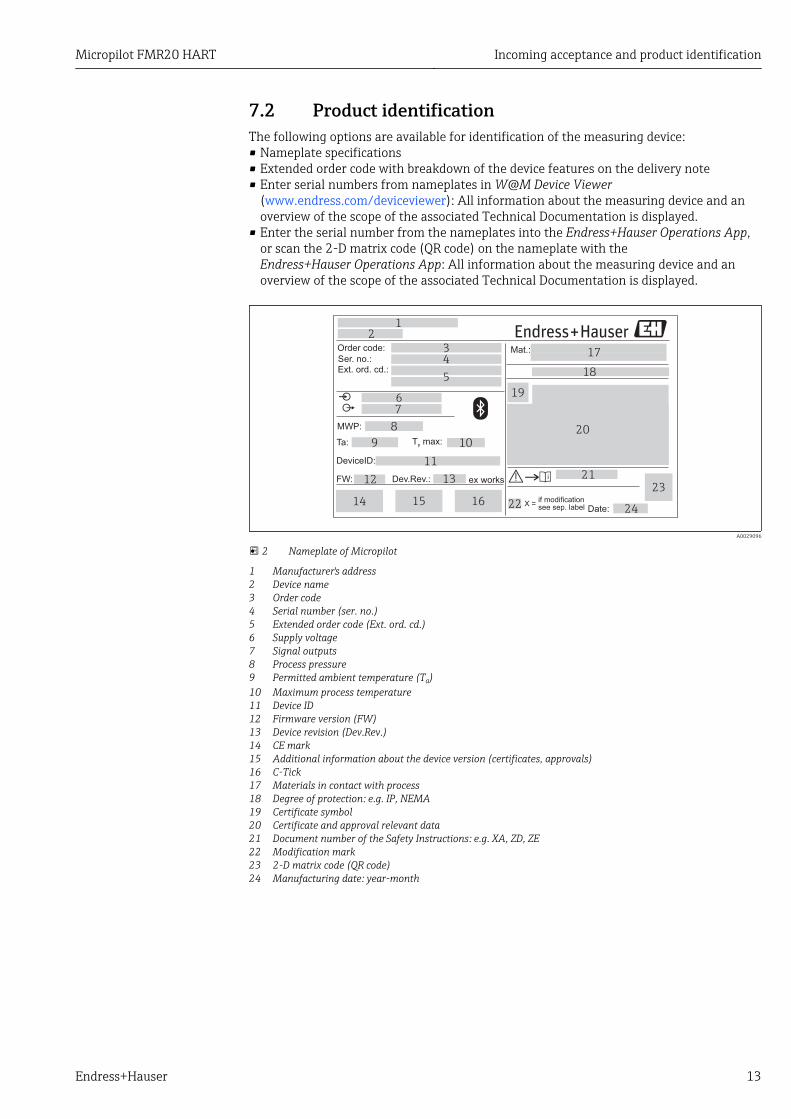
7.2 Product identificationThe following options are available for identification of the measuring device:• Nameplate specifications• Extended order code with breakdown of the device features on the delivery note• Enter serial numbers from nameplates in W@M Device Viewer
(www.endress.com/deviceviewer): All information about the measuring device and anoverview of the scope of the associated Technical Documentation is displayed.
• Enter the serial number from the nameplates into the Endress+Hauser Operations App,or scan the 2-D matrix code (QR code) on the nameplate with theEndress+Hauser Operations App: All information about the measuring device and anoverview of the scope of the associated Technical Documentation is displayed.
12
11
8
7
6
2
1
3
4
5
19
20
18
15 16
13
17
1424
Ext. ord. cd.:
Order code:
Ser. no.:
T max:p
DeviceID:
Date:
FW ex works
Mat.:
: Dev.Rev.:
10Ta:
if modificationsee sep. label
X =
MWP:
23
21
22
9
A0029096
2 Nameplate of Micropilot
1 Manufacturer's address2 Device name3 Order code4 Serial number (ser. no.)5 Extended order code (Ext. ord. cd.)6 Supply voltage7 Signal outputs8 Process pressure9 Permitted ambient temperature (Ta)10 Maximum process temperature11 Device ID12 Firmware version (FW)13 Device revision (Dev.Rev.)14 CE mark15 Additional information about the device version (certificates, approvals)16 C-Tick17 Materials in contact with process18 Degree of protection: e.g. IP, NEMA19 Certificate symbol20 Certificate and approval relevant data21 Document number of the Safety Instructions: e.g. XA, ZD, ZE22 Modification mark23 2-D matrix code (QR code)24 Manufacturing date: year-month
Installation Micropilot FMR20 HART
14 Endress+Hauser
8 Installation
8.1 Installation conditions
8.1.1 Installation types
B C DA
A0030605
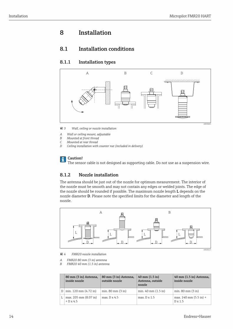
3 Wall, ceiling or nozzle installation
A Wall or ceiling mount, adjustableB Mounted at front threadC Mounted at rear threadD Ceiling installation with counter nut (included in delivery)
Caution!The sensor cable is not designed as supporting cable. Do not use as a suspension wire.
8.1.2 Nozzle installationThe antenna should be just out of the nozzle for optimum measurement. The interior ofthe nozzle must be smooth and may not contain any edges or welded joints. The edge ofthe nozzle should be rounded if possible. The maximum nozzle length L depends on thenozzle diameter D. Please note the specified limits for the diameter and length of thenozzle.
BA
L
D
L
D
L
D
L
D
A0028413
4 FMR20 nozzle installation
A FMR20 80 mm (3 in) antennaB FMR20 40 mm (1.5 in) antenna
80 mm (3 in) Antenna,inside nozzle
80 mm (3 in) Antenna,outside nozzle
40 mm (1.5 in)Antenna, outsidenozzle
40 mm (1.5 in) Antenna,inside nozzle
D min. 120 mm (4.72 in) min. 80 mm (3 in) min. 40 mm (1.5 in) min. 80 mm (3 in)
L max. 205 mm (8.07 in)+ D x 4.5
max. D x 4.5 max. D x 1.5 max. 140 mm (5.5 in) +D x 1.5

Micropilot FMR20 HART Installation
Endress+Hauser 15
8.1.3 Orientation
1
4
1/6D
BD
2 3
D
A0028410
5 Tank installation position
• If possible install the sensor so that its lower edge projects into the vessel.• Do not install the sensor in the middle of the tank (2). We recommend leaving a distance
(1) between the sensor and the tank wall measuring 1/6 of the tank diameter.Recommended distance A wall - nozzle outer edge: ~ 1/6 of the tank diameter D.However, the device must not under any circumstances be mounted closer than15 cm (5.91 in) to the tank wall.
• Avoid measurements through the filling curtain (3).• Avoid equipment (4) such as limit switches, temperature sensors, baffles, heating coils
etc.• Multiple devices can be operated in one tank without influencing each other.• No signals are analyzed within the Blocking distance. It can therefore be used to
suppress interference signals (e.g. the effects of condensate) close to the antenna.By default an automatic Blocking distance of at least 0.1 m (0.33 ft) is preset. However itcan be manually overwritten (even 0 m (0 ft) is allowed.Automatic calculation:Blocking distance = Empty calibration - Full calibration - 0.2 m (0.656 ft).The Blocking distance parameter is recalculated according to this formula every time anew value is entered into the Empty calibration parameter or Full calibrationparameter.If this calculation results in a value <0.1 m (0.33 ft), the blocking distance of0.1 m (0.33 ft) is used instead.
8.1.4 Alignment• Align the antenna vertically to the product surface.• Align the eyelet with the mounting eye as well as possible towards the tank wall.

Installation Micropilot FMR20 HART
16 Endress+Hauser
90°
90°
90°
90°
90°
A0028927
6 Sensor alignment when mounting in tank
8.1.5 Beam angle
a
D
W
a_
2W = 2 x D x tan
A0029053-EN
7 Relationship between beam angle α, distance D and beamwidth diameter W
The beam angle is defined as the angle α at which the power density of the radar wavesreaches half the value of the maximum power density (3dB width). Microwaves are alsoemitted outside the signal beam and can be reflected off interfering installations.
Beam diameter W as a function of beam angle α and measuring distance D.
FMR20
Antenna size 40 mm (1.5 in) 80 mm (3 in)
Beam angle α 30° 12°
Distance (D) Beamwidth diameter W
3 m (9.8 ft) 1.61 m (5.28 ft) 0.63 m (2.1 ft)
5 m (16.4 ft) 2.68 m (8.79 ft) 1.05 m (3.45 ft)
10 m (33 ft) 5.36 m (17.59 ft) 2.1 m (6.9 ft)
15 m (49 ft) 3.15 m (10.34 ft)
20 m (66 ft) 4.2 m (13.79 ft)

Micropilot FMR20 HART Installation
Endress+Hauser 17
8.1.6 Measurement in plastic vesselsIf the outer wall of the vessel is made of a non-conductive material (e.g. GFR) microwavescan also be reflected off interfering installations outside of the vessel (e.g. metallicpipes (1), ladders (2), grates (3), ...). Therefore there should be no such interferinginstallations in the signal beam. For more information, please contact Endress+Hauser.
2
31
A0029540
8 Measurement in a plastic vessel
8.1.7 Weather protection coverFor outdoor use, the use of a weather protection cover(1) is recommended
1
A0031277
9 Weather protection cover, e.g with 40 mm (1.5") antenna
The sensor is not completely covered in the case of the 40 mm (1.5 in) antenna or the80 mm (3 in) antenna.
The weather protection cover is available as an accessory. → 45

Installation Micropilot FMR20 HART
18 Endress+Hauser
8.1.8 Free-field measurement with flooding protection tubeThe flooding protection tube guarantees a definitive analysis of the maximum level even inthe event that the sensor is completely flooded.
In free-field installations and / or in applications where there is a risk of flooding, it isrecommended to use a flooding protection tube
13
4
1
2
3
4
2
A0031093
10 Function of flooding protection tube
1 Air pocket2 O-ring (EPDM) seal3 Blocking distance4 Max. Level
The flooding protection tube is available as an accessory. → 45
The tube is screwed directly onto the sensor and seals off the system by means of an O-ring (2) making it air-tight. In the event of flooding, the air pocket (1) that develops in thetube ensures a definitive detection of the maximum level (4) directly at the end of thetube. Due to the fact that the Blocking distance (3) is inside the tube, multiple echoes arenot analyzed.
Configuring the blocking distance when using the flooding protection tube
‣ Navigate to: Main menu → Setup → Advanced setup → Blocking distance Enter 100 mm (4 in).

Micropilot FMR20 HART Installation
Endress+Hauser 19
8.1.9 Installation with mounting bracket, adjustable
A0030606
11 Installation with mounting bracket, adjustable
• Wall or ceiling installation is possible.• Using the mounting bracket, position the antenna so that it is perpendicular to the
product surface.
NOTICEThere is no conductive connection between the mounting bracket and transmitterhousing.Risk of electrostatic charge.‣ Integrate the mounting bracket in the local potential equalization system.
The mounting bracket is available as an accessory. → 45
8.1.10 Cantilever installation, with pivot
A B C
A0028412
12 Cantilever installation, with pivot
A Installation with cantilever and wall bracketB Installation with cantilever and mounting frameC The cantilever can be turned (e.g. in order to position the sensor over the center of the channel, for example)
The cantilever, wall bracket and mounting frame are available as accessories.→ 45
8.1.11 Post-installation check
Is the device undamaged (visual inspection)?
Is the device adequately protected from wet conditions and direct sunlight?
Is the device properly secured?
Electrical connection Micropilot FMR20 HART
20 Endress+Hauser
9 Electrical connection
9.1 Cable assignment
-+1 2
A0028954
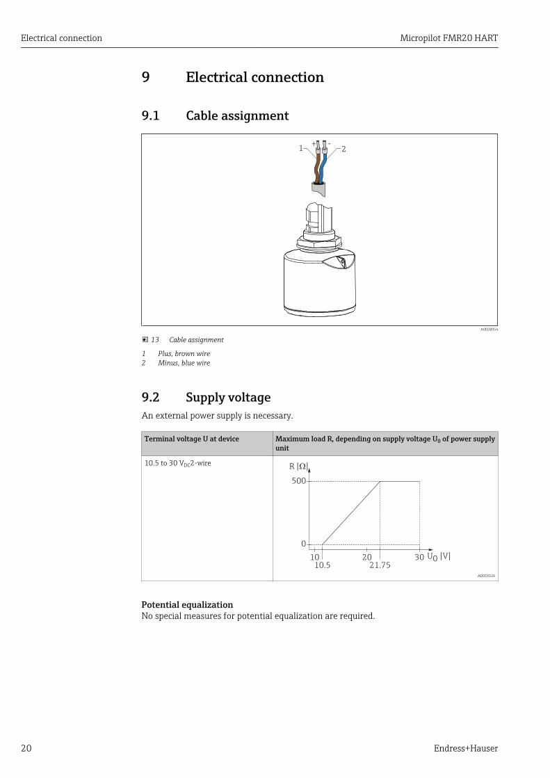
13 Cable assignment
1 Plus, brown wire2 Minus, blue wire
9.2 Supply voltageAn external power supply is necessary.
Terminal voltage U at device Maximum load R, depending on supply voltage U0 of power supplyunit
10.5 to 30 VDC2-wire R [ ]W
U0 [V]1010.5 21.75
20 30
0
500
A0029226
Potential equalizationNo special measures for potential equalization are required.

Micropilot FMR20 HART Electrical connection
Endress+Hauser 21
In the case of a device for the hazardous area, please comply with the safety instructions inthe separate "Safety Instructions" (XA, ZD) document.
Various power supply units can be ordered from Endress+Hauser: see "Accessories"section → 48
Battery operation
The sensor's Bluetooth® wireless technology communication can be disabled toincrease the operating life of the battery.
→ 39
9.3 Connection
9.3.1 FMR20, 4 to 20 mA HART
Circuit diagram / Description
FMR20 connection with HARTcommunication, voltage source and4 to 20 mA display
2
3
Y+ +
- -I
1
mA
A0028908
14 FMR20 block diagram, HART
1 Micropilot FMR202 HART resistance3 Power supply
The HART communication resistor of 250 Ω in the signal line is always necessary inthe case of a low-impedance power supply.
The voltage drop to be taken into account is:Max. 6 V with 250 Ω communication resistor
Electrical connection Micropilot FMR20 HART
22 Endress+Hauser
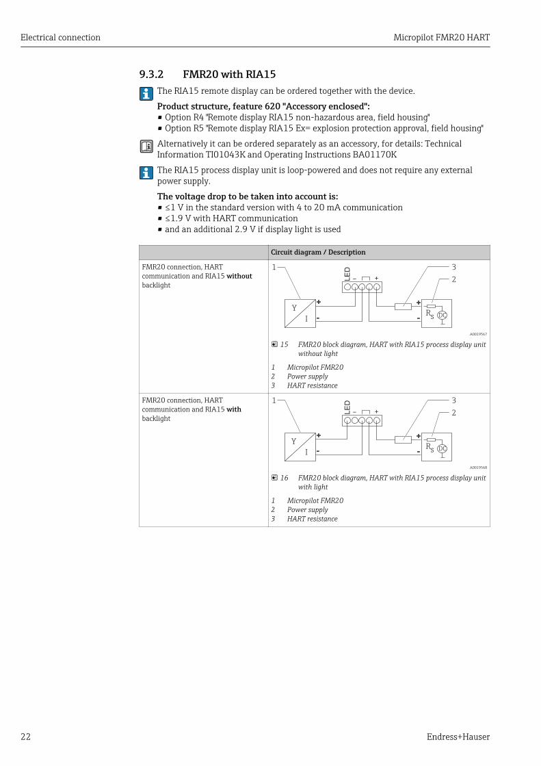
9.3.2 FMR20 with RIA15The RIA15 remote display can be ordered together with the device.
Product structure, feature 620 "Accessory enclosed":• Option R4 "Remote display RIA15 non-hazardous area, field housing"• Option R5 "Remote display RIA15 Ex= explosion protection approval, field housing"
Alternatively it can be ordered separately as an accessory, for details: TechnicalInformation TI01043K and Operating Instructions BA01170K
The RIA15 process display unit is loop-powered and does not require any externalpower supply.
The voltage drop to be taken into account is:• ≤1 V in the standard version with 4 to 20 mA communication• ≤1.9 V with HART communication• and an additional 2.9 V if display light is used
Circuit diagram / Description
FMR20 connection, HARTcommunication and RIA15 withoutbacklight
Y
IR
s DC
1
2
3
LE
D
- +
A0019567
15 FMR20 block diagram, HART with RIA15 process display unitwithout light
1 Micropilot FMR202 Power supply3 HART resistance
FMR20 connection, HARTcommunication and RIA15 withbacklight
Y
IR
s DC
1
2
3
LE
D
- +
A0019568
16 FMR20 block diagram, HART with RIA15 process display unitwith light
1 Micropilot FMR202 Power supply3 HART resistance

Micropilot FMR20 HART Electrical connection
Endress+Hauser 23
9.3.3 FMR20, RIA15 with installed HART communication resistormodule
The HART communication module for installation in the RIA15 can be orderedtogether with the device.
Product structure, feature 620 "Accessory enclosed":• Option R6 "HART communication resistor hazardous / non-hazardous area"• The voltage drop to be taken into account is max. 7 VAlternatively it can be ordered separately as an accessory, for details: TechnicalInformation TI01043K and Operating Instructions BA01170K
Circuit diagram / Description
FMR20 connection and RIA15 withoutbacklight
1
LE
D
- +
32
Y
IR
s DC
A0020839
17 FMR20 block diagram, RIA15 without light, HARTcommunication resistor module
1 HART communication resistor module2 Micropilot FMR203 Power supply
FMR20 connection and RIA15 withbacklight
1
32
Y
IR
s DC
LE
D- +
A0020840
18 FMR20 block diagram, RIA15 with light, HARTcommunication resistor module
1 HART communication resistor module2 Micropilot FMR203 Power supply
9.4 Post-connection check
Is the device or cable undamaged (visual check)?
Do the cables have adequate strain relief?
Are the cable glands mounted and firmly tightened?
Does the supply voltage match the specifications on the nameplate?
No reverse polarity, is terminal assignment correct?
Has the voltage drop across the process display unit and communication resistor been taken into account?
Operability Micropilot FMR20 HART
24 Endress+Hauser
10 Operability
10.1 Operating concept• 4 to 20 mA, HART• Menu guidance with brief explanations of the individual parameter functions in the
operating tool• Optional: SmartBlue (app) via Bluetooth® wireless technology
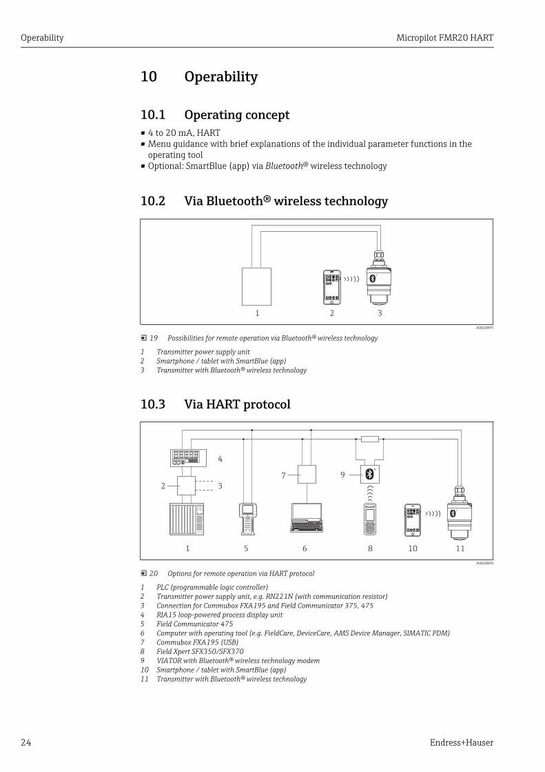
10.2 Via Bluetooth® wireless technology
1 2 3
A0028895
19 Possibilities for remote operation via Bluetooth® wireless technology
1 Transmitter power supply unit2 Smartphone / tablet with SmartBlue (app)3 Transmitter with Bluetooth® wireless technology
10.3 Via HART protocol
1
4
5
7 9
6 8 10 11
2 3
ESC
E+
A0028894
20 Options for remote operation via HART protocol
1 PLC (programmable logic controller)2 Transmitter power supply unit, e.g. RN221N (with communication resistor)3 Connection for Commubox FXA195 and Field Communicator 375, 4754 RIA15 loop-powered process display unit5 Field Communicator 4756 Computer with operating tool (e.g. FieldCare, DeviceCare, AMS Device Manager, SIMATIC PDM)7 Commubox FXA195 (USB)8 Field Xpert SFX350/SFX3709 VIATOR with Bluetooth® wireless technology modem10 Smartphone / tablet with SmartBlue (app)11 Transmitter with Bluetooth® wireless technology

Micropilot FMR20 HART Commissioning and operation
Endress+Hauser 25
11 Commissioning and operation
11.1 Installation and function checkMake sure that all final checks have been completed before you start up your measuringpoint.
11.2 Operation and settings via SmartBlue (app)SmartBlue is available as download for Android devices from the Google Play Store and foriOS devices from the iTunes Store.
If you scan the QR code, you will be brought directly to the app:
A0031189-EN
21 Download Links
System requirements• iOS devices: iPhone 4S or higher from iOS9.0; iPad2 or higher from iOS9.0; iPod Touch
5. Generation or higher from iOS9.0• Android devices: from Android 4.4 KitKat and Bluetooth® 4.0
1. Download and install SmartBlue
2. Start SmartBlue
A0029747

Commissioning and operation Micropilot FMR20 HART
26 Endress+Hauser
3. Select device from livelist. All available devices are displayed.
EH_FMRx0_0123456
A0029502
22 Livelist
4. Perform login
admin
EH_FMRx0_0123456
A0029503
23 Login
5. Enter user name -> admin
6. Enter initial password -> device serial number
7. Change the password after logging in for the first time
Micropilot FMR20 HART Commissioning and operation
Endress+Hauser 27
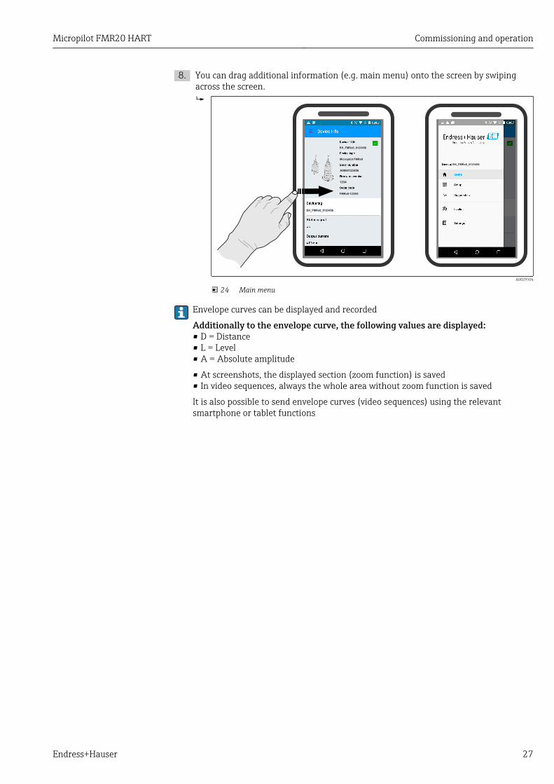
8. You can drag additional information (e.g. main menu) onto the screen by swipingacross the screen.
EH_FMRx0_0123456
EH_FMRx0_0123456
Micropilot FMRx0
FMRx0-1234/0
EH_FMRx0_0123456
1234
A0000123456
A0029504
24 Main menu
Envelope curves can be displayed and recorded
Additionally to the envelope curve, the following values are displayed:• D = Distance• L = Level• A = Absolute amplitude
• At screenshots, the displayed section (zoom function) is saved• In video sequences, always the whole area without zoom function is saved
It is also possible to send envelope curves (video sequences) using the relevantsmartphone or tablet functions

Commissioning and operation Micropilot FMR20 HART
28 Endress+Hauser
1
2
3
4
6
5
A0000123456
0123456x x
A0029486
25 Android view
1 Record video2 Create screenshot3 Start / stop video recording4 Send video5 Navigate to mapping menu6 Move time on time axis

Micropilot FMR20 HART Commissioning and operation
Endress+Hauser 29
5
1
2
3
6
x x
Envelope Curve Map Curve Weighting Curve
4
0123456
A0000123456
A0029487
26 iOS view
1 Record video2 Create screenshot3 Send video4 Navigate to mapping menu5 Start / stop video recording6 Move time on time axis

Commissioning and operation Micropilot FMR20 HART
30 Endress+Hauser
11.3 System integration via HART protocol
11.3.1 Overview of the Device Description Files (DD)
Manufacturer ID 17 (0x11)
Device type ID 44 (0x112c)
HART specification 7.0
DD files Information and files under:• www.endress.com• www.hartcomm.org
11.3.2 Measured variables via HART protocolThe following measured values are assigned to the HART variables:
HART variable Measured value
Primary variable (PV) Level linearized (PV)
Secondary variable (SV) Distance (SV)
Tertiary variable (TV) Relative echo amplitude (TV)
Quaternary variable (QV) Temperature (QV)

Micropilot FMR20 HART Commissioning and operation
Endress+Hauser 31
11.4 Operation and settings via RIA15
1
2
3
4
5
6
7
8
A0017719
27 Display and operating elements of the process display unit
1 Symbol: operating menu disabled2 Symbol: error3 Symbol: warning4 Symbol: HART communication active5 Operating keys "-", "+", "E"6 14-segment display for unit/TAG7 Bar graph with indicators for under range and over range8 5-digit 7-segment display for measured value, digit height 17 mm (0.67 in)
The device is operated using three operating keys on the front of the housing. The devicesetup can be disabled with a 4-digit user code. If the setup is disabled, a padlock symbolappears on the display when an operating parameter is selected.
A0017716
Enter key; calling up the operating menu, confirming the option/setting parameters in theoperating menu
A0017715
Selecting and setting/changing values in the operating menu; pressing the '-' and '+' keyssimultaneously takes the user back up a menu level. The configured value is not saved.
A0017714
11.4.1 Operating functionsThe operating functions of the process display unit are divided into the following menus.The individual parameters and settings are described in the "Commissioning" section.
If the operating menu is disabled by means of a user code, the individual menus andparameters can be displayed but not changed. To change a parameter, the user codemust be entered. As the display unit can only display digits in the 7-segment displayand not alphanumeric characters, the procedure for number parameters is different tothat for text parameters. If the operating position contains only numbers asparameters, the operating position is displayed in the 14-segment display and theconfigured parameter is displayed in the 7-segment display. To edit, press the 'E'-button followed by the user code. If the operating position contains text parameters,only the operating position is initially displayed in the 14-segment display. If the 'E'button is pressed again, the configured parameter is displayed in the 14-segmentdisplay. To edit, press the '+' button followed by the user code.
Setup (SETUP) Basic device settings
Diagnostics (DIAG) Device information, display of error messages
Expert (EXPRT) Expert settings for device setup. The Expert menu is protected from editing by an accesscode (default 0000).
Commissioning and operation Micropilot FMR20 HART
32 Endress+Hauser
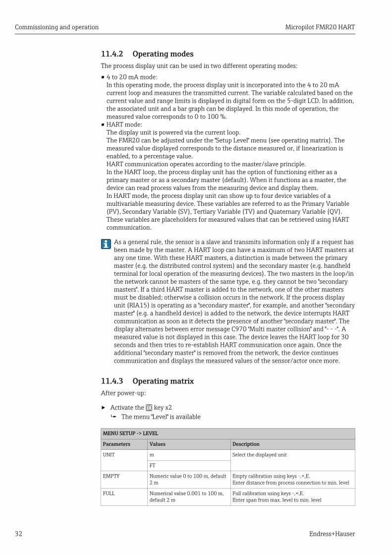
11.4.2 Operating modesThe process display unit can be used in two different operating modes:
• 4 to 20 mA mode:In this operating mode, the process display unit is incorporated into the 4 to 20 mAcurrent loop and measures the transmitted current. The variable calculated based on thecurrent value and range limits is displayed in digital form on the 5-digit LCD. In addition,the associated unit and a bar graph can be displayed. In this mode of operation, themeasured value corresponds to 0 to 100 %.
• HART mode:The display unit is powered via the current loop.The FMR20 can be adjusted under the "Setup Level" menu (see operating matrix). Themeasured value displayed corresponds to the distance measured or, if linearization isenabled, to a percentage value.HART communication operates according to the master/slave principle.In the HART loop, the process display unit has the option of functioning either as aprimary master or as a secondary master (default). When it functions as a master, thedevice can read process values from the measuring device and display them.In HART mode, the process display unit can show up to four device variables of amultivariable measuring device. These variables are referred to as the Primary Variable(PV), Secondary Variable (SV), Tertiary Variable (TV) and Quaternary Variable (QV).These variables are placeholders for measured values that can be retrieved using HARTcommunication.
As a general rule, the sensor is a slave and transmits information only if a request hasbeen made by the master. A HART loop can have a maximum of two HART masters atany one time. With these HART masters, a distinction is made between the primarymaster (e.g. the distributed control system) and the secondary master (e.g. handheldterminal for local operation of the measuring devices). The two masters in the loop/inthe network cannot be masters of the same type, e.g. they cannot be two "secondarymasters". If a third HART master is added to the network, one of the other mastersmust be disabled; otherwise a collision occurs in the network. If the process displayunit (RIA15) is operating as a "secondary master", for example, and another "secondarymaster" (e.g. a handheld device) is added to the network, the device interrupts HARTcommunication as soon as it detects the presence of another "secondary master". Thedisplay alternates between error message C970 "Multi master collision" and "- - -". Ameasured value is not displayed in this case. The device leaves the HART loop for 30seconds and then tries to re-establish HART communication once again. Once theadditional "secondary master" is removed from the network, the device continuescommunication and displays the measured values of the sensor/actor once more.
11.4.3 Operating matrixAfter power-up:
‣ Activate the key x2 The menu "Level" is available
MENU SETUP -> LEVEL
Parameters Values Description
UNIT m Select the displayed unit
FT
EMPTY Numeric value 0 to 100 m, default2 m
Empty calibration using keys -,+,E.Enter distance from process connection to min. level
FULL Numerical value 0.001 to 100 m,default 2 m
Full calibration using keys -,+,E.Enter span from max. level to min. level
Micropilot FMR20 HART Commissioning and operation
Endress+Hauser 33
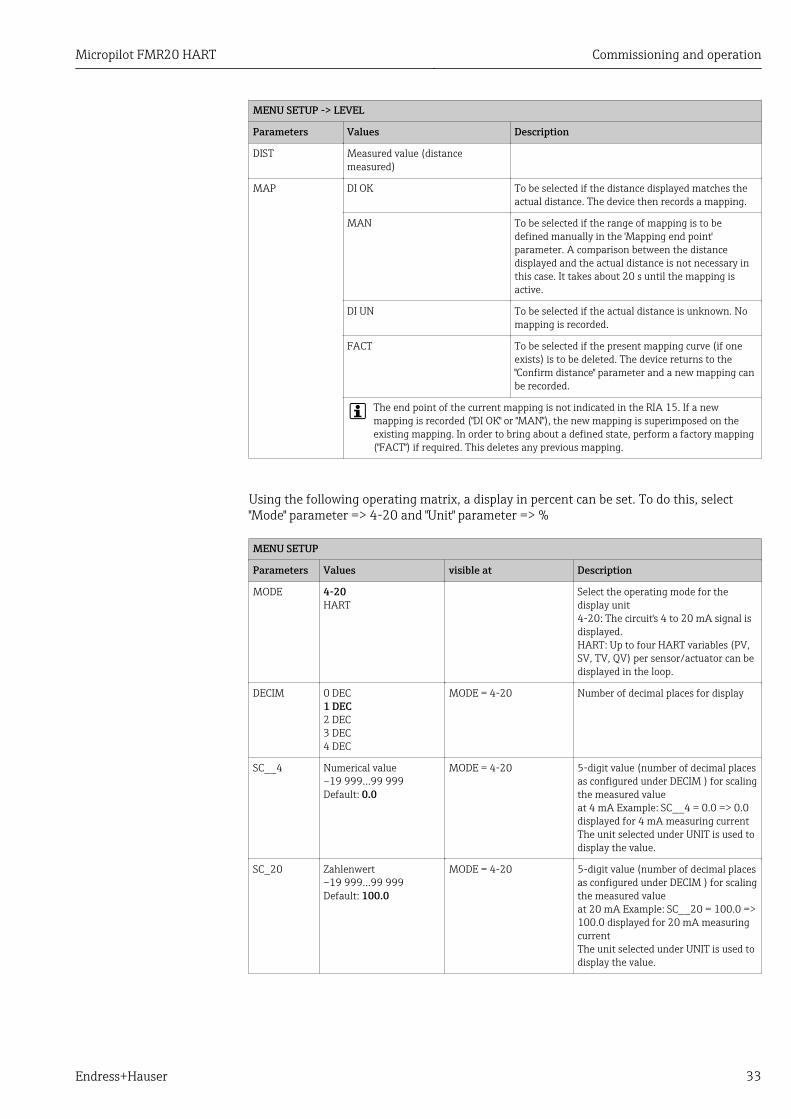
MENU SETUP -> LEVEL
Parameters Values Description
DIST Measured value (distancemeasured)
MAP DI OK To be selected if the distance displayed matches theactual distance. The device then records a mapping.
MAN To be selected if the range of mapping is to bedefined manually in the 'Mapping end point'parameter. A comparison between the distancedisplayed and the actual distance is not necessary inthis case. It takes about 20 s until the mapping isactive.
DI UN To be selected if the actual distance is unknown. Nomapping is recorded.
FACT To be selected if the present mapping curve (if oneexists) is to be deleted. The device returns to the"Confirm distance" parameter and a new mapping canbe recorded.
The end point of the current mapping is not indicated in the RIA 15. If a newmapping is recorded ("DI OK" or "MAN"), the new mapping is superimposed on theexisting mapping. In order to bring about a defined state, perform a factory mapping("FACT") if required. This deletes any previous mapping.
Using the following operating matrix, a display in percent can be set. To do this, select"Mode" parameter => 4-20 and "Unit" parameter => %
MENU SETUP
Parameters Values visible at Description
MODE 4-20HART
Select the operating mode for thedisplay unit4-20: The circuit's 4 to 20 mA signal isdisplayed.HART: Up to four HART variables (PV,SV, TV, QV) per sensor/actuator can bedisplayed in the loop.
DECIM 0 DEC1 DEC2 DEC3 DEC4 DEC
MODE = 4-20 Number of decimal places for display
SC__4 Numerical value–19 999…99 999Default: 0.0
MODE = 4-20 5-digit value (number of decimal placesas configured under DECIM ) for scalingthe measured valueat 4 mA Example: SC__4 = 0.0 => 0.0displayed for 4 mA measuring currentThe unit selected under UNIT is used todisplay the value.
SC_20 Zahlenwert–19 999…99 999Default: 100.0
MODE = 4-20 5-digit value (number of decimal placesas configured under DECIM ) for scalingthe measured valueat 20 mA Example: SC__20 = 100.0 =>100.0 displayed for 20 mA measuringcurrentThe unit selected under UNIT is used todisplay the value.

Commissioning and operation Micropilot FMR20 HART
34 Endress+Hauser
MENU SETUP
Parameters Values visible at Description
UNIT %°C°FKUSER
MODE = 4-20 Use this function to select the unit fordisplaying the value. If "USER" isselected, a user-defined unit can beentered in the TEXT parameter.
TEXT Customized text, 5-digit MODE = 4-20 User-defined unit, only visible if the"USER" option has been selected underUNIT.
Any additional settings such as linearizations must be made using FieldCare,DeviceCare or SmartBlue.
Additional information is available in the RIA15 Operating Instructions BA01170K.
11.5 Configuring level measurement via operatingsoftware
RBD
100%
0%
D
L
FE
A0028417
28 Configuration parameters for level measurement in liquids
R Reference point of measurementD DistanceL LevelE Empty calibration (= zero point)F Full calibration (= span)BD Blocking distance
1. Navigate to: Setup → Device tag Enter device tag
2. Navigate to: Setup → Distance unit Select unit of length for distance calculation
3. Navigate to: Setup → Empty calibration Specify empty distance E (distance from reference point R to minimum level)
4. Navigate to: Setup → Full calibration Specify full distance F (span: max. level - min. level)
5. Navigate to: Setup → Distance Shows the distance D that is currently measured from the reference point (lower
edge of flange / last thread of the sensor) to the level

Micropilot FMR20 HART Commissioning and operation
Endress+Hauser 35
6. Navigate to: Setup → Level Shows the level L measured
7. Navigate to: Setup → Signal quality Displays the signal quality of the analyzed level echo
8. Navigate to: Setup → Confirm distance Compare the distance displayed with the actual value to start recording an
interference echo map
9. Navigate to: Setup → Mapping end point This parameter determines the distance up to which the new mapping is to be
recorded
10. Navigate to: Setup → Present mapping Displays the distance up to which a mapping has already been recorded
11.5.1 Displaying level value as %In combination Full calibration with Empty calibration and given 4 to 20 mA output signal,the level value for 4 mA (=Empty) and the level value for 20 mA (=Full) can be determineddirectly in the unit of length used.
The Full calibration can be used to calculate a standardized signal proportionate to thelevel e.g. 0 to 100 % level. The two basic values of 0 % and 100 % can in turn be assigneddirectly to the analog output values 4 mA and 20 mA.
X Level in m Y Output signal as %
X1 0.00 m (0.00 ft) Y1 0 %
X2 Value F (=Full) Y2 100 %
Configuration using DeviceCare or FieldCare1. Navigate to: Setup → Advanced setup
Select table as the linearization type
2. Call up the linearization table
3. X1 = Specify level value in m / ft for 0 %
4. X2 = X1 = Specify level value in m / ft for 100 %
5. Confirm table as the linearization type
Configuration using SmartBlue1. Navigate to: Main menu → Setup → Advanced setup → Linearization type
Select table as the linearization type
2. Select linearization table
3. X1 = Specify level value in m / ft for 0 %
4. X2 = Specify level value in m / ft for 100 %
5. Activate linearization table

Commissioning and operation Micropilot FMR20 HART
36 Endress+Hauser
11.6 Configuring Flow measurement via operatingsoftware
11.6.1 Installation conditions for Flow measurement• In order to realize a flow measurement, a channel or a weir is required• Place the sensor in the middle of the channel or weir• Align the sensor perpendicular to the water surface• Use a weather protection cover to protect the device against sunlight and rain• We recommend the use of the accessories "flooding protection tube"
D
Q
A0028414
29 Configuration parameters for flow measurement in liquids
D DistanceQ Flow of weirs or flumes (from the level by linearization calculated)
11.6.2 Configuring Flow measurement
E
D
L
A0030325
30 Sample: Khafagi Venturi flume
E Empty calibrationD DistanceL Level

Micropilot FMR20 HART Commissioning and operation
Endress+Hauser 37
E
D
L
A0030326
31 Sample: Notch weir
E Empty calibrationD DistanceL Level
1. Navigate to: Setup → Device tag Enter device tag.
2. Navigate to: Setup → Distance unit Select unit of length for distance calculation.
3. Navigate to: Setup → Empty calibration Specify empty distance E (distance from reference point R to minimum level)
At flumes the zero point is the bottom at the narrowest point.
4. Navigate to: Setup → Full calibration Specify full distance F (span: max. level - min. level)
5. Navigate to: Setup → Distance Shows the distance D that is currently measured from the reference point (lower
edge of sensor) to the level.
6. Navigate to: Setup → Level Shows the level L measured.
7. Navigate to: Setup → Signal quality Displays the signal quality of the analyzed level echo.
8. Navigate to: Setup → Confirm distance Compare the distance displayed with the actual value to start recording an
interference echo map.
9. Navigate to: Setup → Mapping end point This parameter determines the distance up to which the new mapping is to be
recorded.
10. Navigate to: Setup → Present mapping Displays the distance up to which a mapping has already been recorded.
Linearization via DeviceCare / FieldCare1. Select Linearization Table
2. Start QH Program
3. Save calculated data and then write to the device

Commissioning and operation Micropilot FMR20 HART
38 Endress+Hauser
Linearization via SmartBlue1. Navigate to: Setup → Advanced setup
Linearization table
2. Select unit for lenght
3. Select unit displayed after linearization
4. Linearization type Select table
5. Select table mode "manuel"
6. Manually insert value pairs (maximum of 32) into table. Table has to be in mode"diasabled"
7. Enable table

Micropilot FMR20 HART Commissioning and operation
Endress+Hauser 39
11.7 Data access - Security
11.7.1 Software locking via access code in FieldCare / DeviceCareThe configuration data can be write-protected using an access code (software locking).
‣ Navigate to: Setup → Advanced setup → Administration → Define access code →Confirm access code
The entered code must be different from "0000" and the last release code.
Once the access code has been defined, write-protected devices can be switched tomaintenance mode only if the access code is entered in the Enter access code parameter.If the factory setting is not changed or if 0000 is entered, the device is in maintenancemode and its configuration data are therefore not write-protected and can be changed atany time.
11.7.2 Unlocking via FieldCare / DeviceCare‣ Navigate to: Setup → Advanced setup → Enter access code
11.7.3 Software locking via access code in SmartBlueThe configuration data can be write-protected using an access code (software locking).
‣ Navigate to: Setup → Advanced setup → Administration → Administration1 → Defineaccess code → Confirm access code
The entered code must be different from "0000" and the last release code.
Once the access code has been defined, write-protected devices can be switched tomaintenance mode only if the access code is entered in the Enter access code parameter.If the factory setting is not changed or if 0000 is entered, the device is in maintenancemode and its configuration data are therefore not write-protected and can be changed atany time.
11.7.4 Unlocking via SmartBlue‣ Navigate to: Setup → Advanced setup → Zugriffsrechte Bediensoftware → Enter access
code
11.7.5 Bluetooth® wireless technologySignal transmission via Bluetooth® wireless technology is done by an ecryptionmethod tested by the Fraunhofer-Institut (Third Party).• Without the SmartBlue App, the device is not visible via Bluetooth® wireless technology• Only one point-to-point connection between one sensor and one smartphone or tablet is
established.• The Bluetooth® wireless technology interface can be deactivated in SmartBlue, FieldCare
and DeviceCare
Deactivate Bluetooth® wireless technology interface
‣ Navigate to: Setup → Communication → Bluetooth configuration → Bluetooth mode Switch off Bluetooth® wireless technology interface. "Off" position disables remote
access via app
Commissioning and operation Micropilot FMR20 HART
40 Endress+Hauser
Re-activate Bluetooth® wireless technology interfaceIf Bluetooth® wireless technology interface was disabled, it can be re-activated anytime viaFieldCare / DeviceCare
‣ Navigate to: Setup → Communication → Bluetooth configuration → Bluetooth mode Switch on Bluetooth® wireless technology interface. "On" position enables remote
access via app
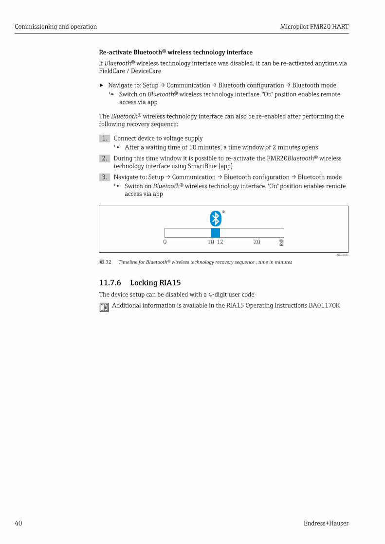
The Bluetooth® wireless technology interface can also be re-enabled after performing thefollowing recovery sequence:
1. Connect device to voltage supply After a waiting time of 10 minutes, a time window of 2 minutes opens
2. During this time window it is possible to re-activate the FMR20Bluetooth® wirelesstechnology interface using SmartBlue (app)
3. Navigate to: Setup → Communication → Bluetooth configuration → Bluetooth mode Switch on Bluetooth® wireless technology interface. "On" position enables remote
access via app
10 120 20 6
A0028411
32 Timeline for Bluetooth® wireless technology recovery sequence , time in minutes
11.7.6 Locking RIA15The device setup can be disabled with a 4-digit user code
Additional information is available in the RIA15 Operating Instructions BA01170K
Micropilot FMR20 HART Diagnostics and troubleshooting
Endress+Hauser 41
12 Diagnostics and troubleshooting
12.1 General trouble shooting
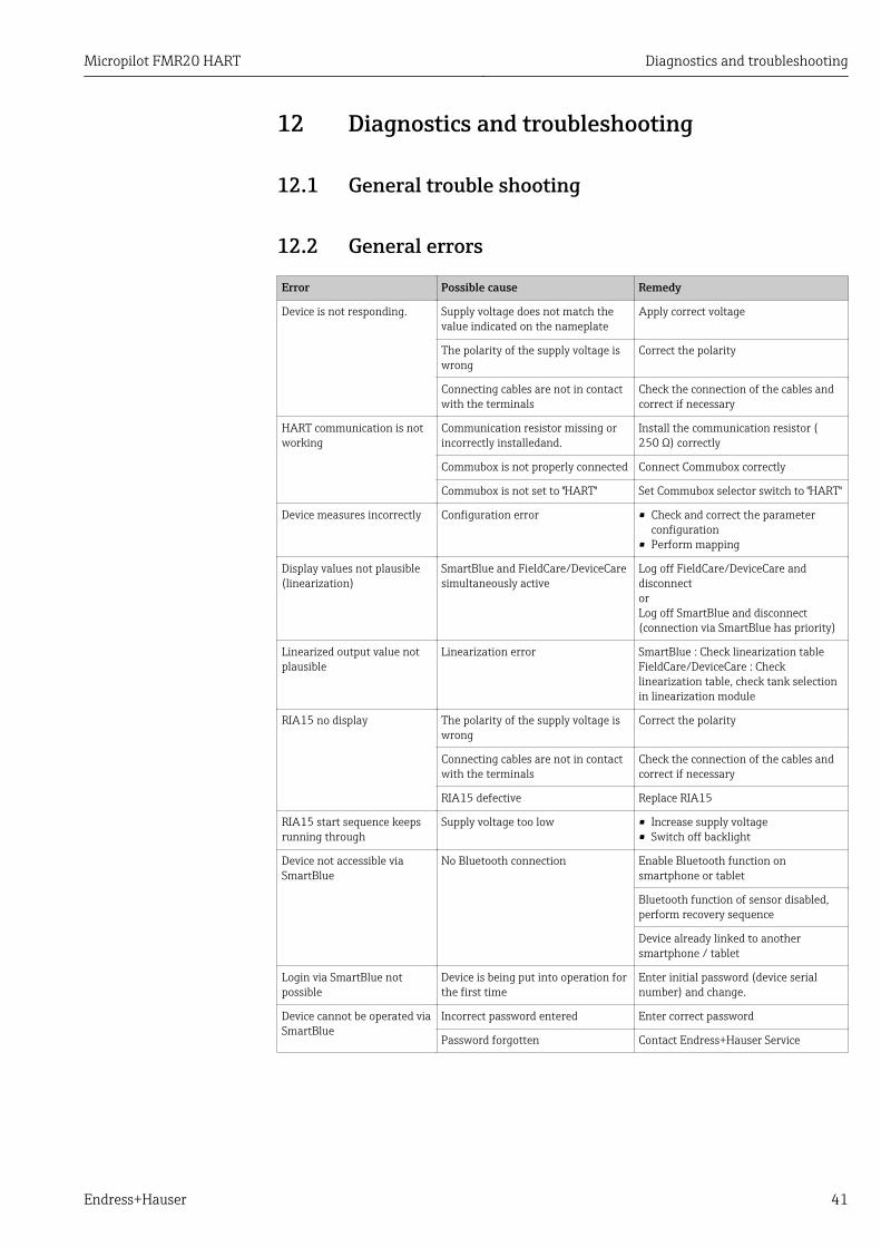
12.2 General errors
Error Possible cause Remedy
Device is not responding. Supply voltage does not match thevalue indicated on the nameplate
Apply correct voltage
The polarity of the supply voltage iswrong
Correct the polarity
Connecting cables are not in contactwith the terminals
Check the connection of the cables andcorrect if necessary
HART communication is notworking
Communication resistor missing orincorrectly installedand.
Install the communication resistor (250 Ω) correctly
Commubox is not properly connected Connect Commubox correctly
Commubox is not set to "HART" Set Commubox selector switch to "HART"
Device measures incorrectly Configuration error • Check and correct the parameterconfiguration
• Perform mapping
Display values not plausible(linearization)
SmartBlue and FieldCare/DeviceCaresimultaneously active
Log off FieldCare/DeviceCare anddisconnectorLog off SmartBlue and disconnect(connection via SmartBlue has priority)
Linearized output value notplausible
Linearization error SmartBlue : Check linearization tableFieldCare/DeviceCare : Checklinearization table, check tank selectionin linearization module
RIA15 no display The polarity of the supply voltage iswrong
Correct the polarity
Connecting cables are not in contactwith the terminals
Check the connection of the cables andcorrect if necessary
RIA15 defective Replace RIA15
RIA15 start sequence keepsrunning through
Supply voltage too low • Increase supply voltage• Switch off backlight
Device not accessible viaSmartBlue
No Bluetooth connection Enable Bluetooth function onsmartphone or tablet
Bluetooth function of sensor disabled,perform recovery sequence
Device already linked to anothersmartphone / tablet
Login via SmartBlue notpossible
Device is being put into operation forthe first time
Enter initial password (device serialnumber) and change.
Device cannot be operated viaSmartBlue
Incorrect password entered Enter correct password
Password forgotten Contact Endress+Hauser Service
Diagnostics and troubleshooting Micropilot FMR20 HART
42 Endress+Hauser
12.3 Diagnostic event
12.3.1 Diagnostic event in the operating toolIf a diagnostic event is present in the device, the status signal appears in the top left statusin the operating tool along with the corresponding symbol for event level in accordancewith NAMUR NE 107:
• Failure (F)• Function check (C)• Out of specification (S)• Maintenance required (M)
Calling up remedy information1. Navigate to the Diagnostics menu.
In the Actual diagnostics parameter, the diagnostic event is shown with eventtext
2. On the right in the display range, hover the cursor over the Actual diagnosticsparameter. A tool tip with remedy information for the diagnostic event appears
12.3.2 Diagnostic event in the RIA15In RIA15 a diagnostic event of FMR20 is not directly displayed. On RIA15 the error F911 isdisplayed only when the FMR20 issues an alarm.
Display the FMR20 diagnostic event in RIA151. Navigate to: DIAG/TERR
2. press
3. press
4. press
5. press 3x
6. press The diagnostic event from FMR20 appears on the RIA15 display
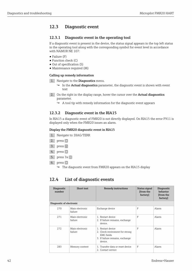
12.4 List of diagnostic events
Diagnosticnumber
Short text Remedy instructions Status signal[from thefactory]
Diagnosticbehavior[from thefactory]
Diagnostic of electronic
270 Main electronicfailure
Exchange device F Alarm
271 Main electronicfailure
1. Restart device2. If failure remains, exchange
device.
F Alarm
272 Main electronicfailure
1. Restart device2. Check enviroment for strong
EMC fields3. If failure remains, exchange
device.
F Alarm
283 Memory content 1. Transfer data or reset device2. Contact service
F Alarm

Micropilot FMR20 HART Maintenance
Endress+Hauser 43
Diagnosticnumber
Short text Remedy instructions Status signal[from thefactory]
Diagnosticbehavior[from thefactory]
Diagnostic of configuration
410 Data transfer 1. Check connection2. Retry data transfer
F Alarm
411 Up-/download active Up-/download active, please wait C Warning
435 Linearization Check linearization table F Alarm
438 Dataset 1. Check data set file2. Check device configuration3. Up- and download new
configuration
M Warning
441 Current output 1 1. Check process2. Check current output settings
S Warning
491 Current output 1simulation
Deactivate simulation C Warning
585 Simulation distance Deactivate simulation C Warning
586 Record map Recording of mappingplease wait
C Warning
Diagnostic of process
801 Energy too low Increase supply voltage S Warning
825 Operatingtemperature
1. Check ambient temperature2. Check process temperature
S Warning
941 Echo lost Check parameter 'Evaluationsensitivity'
S Warning
941 Echo lost F Alarm
12.5 Overview of information events
Info number Info name
I1000 --------(Device ok)
13 MaintenanceNo special maintenance work is required.
13.1 Exterior cleaningWhen cleaning the exterior, always use cleaning agents that do not attack the devicesurfaces or the seals.
13.2 SealsThe process seals of the sensor (at the process connection) should be replaced periodically.The interval between changes depends on the frequency of the cleaning cycles, thecleaning temperature and the medium temperature.

Repair Micropilot FMR20 HART
44 Endress+Hauser
14 Repair
14.1 General notes
14.1.1 Repair conceptThe Endress+Hauser repair concept is devised in such a way that repairs can only becarried out through device replacement.
14.1.2 Replacing a deviceAfter the device has been replaced, parameters can be loaded onto the device once againvia FieldCare/DeviceCare.
Condition: The configuration of the old device must have been saved using FieldCare/DeviceCare.
You can continue to measure without performing a new calibration. Only interference echosuppression may need to be carried out once again.
14.1.3 ReturnThe measuring device must be returned if the wrong device has been ordered or delivered.As an ISO-certified company and also due to legal regulations, Endress+Hauser is obligedto follow certain procedures when handling any returned products that have been incontact with medium. To ensure safe, swift and professional device returns, please refer tothe procedure and conditions for returning devices provided on the Endress+Hauserwebsite at http://www.endress.com/support/return-material
14.1.4 DisposalWhen disposing, separate and recycle the device components based on the materials.

Micropilot FMR20 HART Accessories
Endress+Hauser 45
15 Accessories
15.1 Overview
Device-specific accessories
Accessories Description Order number
Weather protectioncover
Material: PVDF
The sensor is not completely covered.
52025686Product structure, feature 620"Accessory enclosed", option R1"Weather protection cover"
Securing nut G1-1/2 Suitable for use with devices with G 1-1/2and MNPT 1-1/2 process connection.Material: PC
52014146
Securing nut G2 Suitable for use with devices with G 2 andMNPT 2 process connection at front.Material: PC
52000598
Flooding protectiontube40 mm (1.5 in)Antenne
Material: metallized PBT-PC 71325090Product structure, feature 620"Accessory enclosed", option R7"Flooding protection tube, metallizedPBT-PC suitable for 40 mm (1.5 in)antenna with G1-1/2 processconnection on front
Flooding protectiontube80 mm (3 in) antenna
Material: metallized PBT-PC 71327051Product structure, feature 620"Accessory enclosed", option R8"Flooding protection tube, metallizedPBT-PC suitable for 80 mm (3 in)antenna
Mounting bracket,adjustable
Consists of:• Mounting bracket: 316L (1.4404)• Angle bracket: 316L (1.4404)• Screws: A4• Retaining rings: A4
71325079Product structure, feature 620"Accessory enclosed", option R3"Mounting bracket, adjustable, 316L"
Angle bracket for wallmount
Suitable for G 1-1/2 and MNPT 1-1/2process connectionMaterial: 316Ti (1.4571)
942669-0000
Suitable for G 2 and MNPT 2 processconnectionMaterial: 316Ti (1.4571)
942669-0001
Ceiling mountingbracket
Material: 316L (1.4404) 71093130Product structure, feature 620"Accessory enclosed", option R2"Ceiling mounting bracket, 316L"
RIA15 in the fieldhousing
Remote display RIA15 non-hazardous Product structure, feature 620"Accessory enclosed", option R4"Remote display RIA15 non-hazardousarea, field housing"
Remote display RIA15 hazardous Product structure, feature 620"Accessory enclosed", option R5"Remote display RIA15 Ex= explosionprotection approval, field housing"
HART communicationresistor
HART communication resistor,hazardous / non-hazardous area, for use withRIA15
Product structure, feature 620"Accessory enclosed", option R6 "HARTcommunication resistor hazardous /non-hazardous area"
Accessories Micropilot FMR20 HART
46 Endress+Hauser
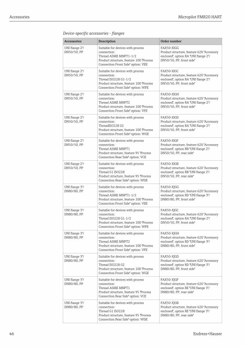
Device-specific accessories - flanges
Accessories Description Order number
UNI flange 2"/DN50/50, PP
Suitable for devices with processconnection:Thread ASME MNPT1-1/2Product structure, feature 100 "ProcessConnection Front Side" option: VEE
FAX50-XIGGProduct structure, feature 620 "Accessoryenclosed", option RA "UNI flange 2"/DN50/50, PP, front side"
UNI flange 2"/DN50/50, PP
Suitable for devices with processconnection:Thread ISO228 G1-1/2Product structure, feature 100 "ProcessConnection Front Side" option: WFE
FAX50-XIGCProduct structure, feature 620 "Accessoryenclosed", option RA "UNI flange 2"/DN50/50, PP, front side"
UNI flange 2"/DN50/50, PP
Suitable for devices with processconnection:Thread ASME MNPT2Product structure, feature 100 "ProcessConnection Front Side" option: VFE
FAX50-XIGHProduct structure, feature 620 "Accessoryenclosed", option RA "UNI flange 2"/DN50/50, PP, front side"
UNI flange 2"/DN50/50, PP
Suitable for devices with processconnection:ThreadISO228 G2Product structure, feature 100 "ProcessConnection Front Side" option: WGE
FAX50-XIGDProduct structure, feature 620 "Accessoryenclosed", option RA "UNI flange 2"/DN50/50, PP, front side"
UNI flange 2"/DN50/50, PP
Suitable for devices with processconnection:Thread ASME MNPT1Product structure, feature 95 "ProcessConnection Rear Side" option: VCE
FAX50-XIGFProduct structure, feature 620 "Accessoryenclosed", option RB "UNI flange 2"/DN50/50, PP, rear side"
UNI flange 2"/DN50/50, PP
Suitable for devices with processconnection:Thread G1 ISO228Product structure, feature 95 "ProcessConnection Rear Side" option: WDE
FAX50-XIGBProduct structure, feature 620 "Accessoryenclosed", option RB "UNI flange 2"/DN50/50, PP, rear side"
UNI flange 3"/DN80/80, PP
Suitable for devices with processconnection:Thread ASME MNPT1-1/2Product structure, feature 100 "ProcessConnection Front Side" option: VEE
FAX50-XJGGProduct structure, feature 620 "Accessoryenclosed", option RD "UNI flange 3"/DN80/80, PP, front side"
UNI flange 3"/DN80/80, PP
Suitable for devices with processconnection:Thread ISO228 G1-1/2Product structure, feature 100 "ProcessConnection Front Side" option: WFE
FAX50-XJGCProduct structure, feature 620 "Accessoryenclosed", option RA "UNI flange 2"/DN50/50, PP, front side"
UNI flange 3"/DN80/80, PP
Suitable for devices with processconnection:Thread ASME MNPT2Product structure, feature 100 "ProcessConnection Front Side" option: VFE
FAX50-XJGHProduct structure, feature 620 "Accessoryenclosed", option RD "UNI flange 3"/DN80/80, PP, front side"
UNI flange 3"/DN80/80, PP
Suitable for devices with processconnection:Thread ISO228 G2Product structure, feature 100 "ProcessConnection Front Side" option: WGE
FAX50-XJGDProduct structure, feature 620 "Accessoryenclosed", option RD "UNI flange 3"/DN80/80, PP, front side"
UNI flange 3"/DN80/80, PP
Suitable for devices with processconnection:Thread ASME MNPT1Product structure, feature 95 "ProcessConnection Rear Side" option: VCE
FAX50-XJGFProduct structure, feature 620 "Accessoryenclosed", option RE "UNI flange 3"/DN80/80, PP, rear side"
UNI flange 3"/DN80/80, PP
Suitable for devices with processconnection:Thread G1 ISO228Product structure, feature 95 "ProcessConnection Rear Side" option: WDE
FAX50-XJGBProduct structure, feature 620 "Accessoryenclosed", option RE "UNI flange 3"/DN80/80, PP, rear side"

Micropilot FMR20 HART Accessories
Endress+Hauser 47
Accessories Description Order number
UNI flange 4"/DN100/100,PP
Suitable for devices with processconnection:Thread ASME MNPT1-1/2Product structure, feature 100 "ProcessConnection Front Side" option: VEE
FAX50-XKGGProduct structure, feature 620 "Accessoryenclosed", option RG "UNI flange 4"/DN100/100,PP, front side"
UNI flange 4"/DN100/100,PP
Suitable for devices with processconnection:Thread ISO228 G1-1/2Product structure, feature 100 "ProcessConnection Front Side" option: WFE
FAX50-XKGCProduct structure, feature 620 "Accessoryenclosed", option RG "UNI flange 4"/DN100/100,PP, front side"
UNI flange 4"/DN100/100,PP
Suitable for devices with processconnection:Thread ASME MNPT2Product structure, feature 100 "ProcessConnection Front Side" option: VFE
FAX50-XKGHProduct structure, feature 620 "Accessoryenclosed", option RG "UNI flange 4"/DN100/100,PP, front side"
UNI flange 4"/DN100/100,PP
Suitable for devices with processconnection:Thread ISO228 G2Product structure, feature 100 "ProcessConnection Front Side" option: WGE
FAX50-XKGDProduct structure, feature 620 "Accessoryenclosed", option RG "UNI flange 4"/DN100/100,PP, front side"
UNI flange 4"/DN100/100, PP
Suitable for devices with processconnection:Thread ASME MNPT1Product structure, feature 95 "ProcessConnection Rear Side" option: VCE
FAX50-XKGFProduct structure, feature 620 "Accessoryenclosed", option RH "UNI flange 4"/DN100/100,PP, rear side"
UNI flange 4"/DN100/100, PP
Suitable for devices with processconnection:Thread G1 ISO228Product structure, feature 95 "ProcessConnection Rear Side" option: WDE
FAX50-XKGBProduct structure, feature 620 "Accessoryenclosed", option RH "UNI flange 4"/DN100/100,PP, rear side"
Flanges Material: miscellaneous For details, see TechnicalInformation TI00426F
Device-specific accessories - cantilever pivotally
Zubehör Beschreibung Bestellnummer
Cantilever with pivot, sensor processconnection on rear G 1 or MNPT 1
Length:585 mm (23 in)
• Steel, hot-dip galvanized:919790-0000
• 316Ti (1.4571): 919790-0001
Length:1 085 mm (42.7 in)
• Steel, hot-dip galvanized:919790-0002
• 316Ti (1.4571): 919790-0003
Cantilever with pivot, sensor processconnection on front G 1 -1/2 or MNPT1-1/2
Length:585 mm (23 in)
• Steel, hot-dip galvanized: 52014131• 316Ti (1.4571): 52014132
Length:1 085 mm (42.7 in)
• Steel, hot-dip galvanized: 52014133• 316Ti (1.4571): 52014134
Cantilever, sensor process connection onfront G 2 or MNPT 2
Length:585 mm (23 in)
• Steel, hot-dip galvanized: 52014135• 316Ti (1.4571): 52014136
Length:1 085 mm (42.7 in)
• Steel, hot-dip galvanized: 52014137• 316Ti (1.4571): 52014138
Mounting stand for cantilever with pivot Height:700 mm (27.6 in)
• Steel, galvanized: 919791-0000• 316Ti (1.4571): 919791-0001
Height:1 400 mm (55.1 in)
• Steel, galvanized: 919791-0002• 316Ti (1.4571): 919791-0003
Wall bracket for cantilever with pivot • Steel, galvanized: 919792-0000• 316Ti (1.4571): 919792-0001

Accessories Micropilot FMR20 HART
48 Endress+Hauser
Communication-specific accessories
Accessories Description Reference
CommuboxFXA195 HART
For intrinsically safe HART communication withFieldCare / DeviceCare via USB interface. For details, see Technical
Information TI00404F
HART LoopConverter HMX50
Is used to evaluate and convert dynamic HART processvariables to analog current signals or limit values. For details, see Technical
Information TI00429Fand OperatingInstructions BA00371F
Order number: 71063562
WirelessHARTadapter SWA70
Is used for the wireless connection of field devices.The WirelessHART adapter can be easily integrated intofield devices and existing infrastructures, offers dataprotection and transmission safety and can be operatedin parallel with other wireless networks.
For details, seeOperating InstructionsBA00061S
Fieldgate FXA320 Gateway for remote monitoring of field devices with4 to 20 mA and digital output signal For details, see Technical
Information TI00025Sand OperatingInstructions BA00053S
Fieldgate FXA520HART
Gateway for remote monitoring of field devices withHART / 4 to 20 mA and digital output signal For details, see Technical
Information TI00025Sand OperatingInstructions BA00051S
Field Xpert SFX350 Field Xpert SFX350 is a mobile computer forcommissioning and maintenance. It enables efficientdevice configuration and diagnostics for HART andFOUNDATION Fieldbus devices in non-hzardous areas.
For details, seeOperating InstructionsBA01202S
Field Xpert SFX370 Field Xpert SFX370 is a mobile computer forcommissioning and maintenance. It enables efficientdevice configuration and diagnostics for HART andFOUNDATION Fieldbus devices in non-hazardous areasand hazardous areas.
For details, seeOperating InstructionsBA01202S
Service-specific accessories
Accessories Description Reference
FieldCare /DeviceCare
FDT-based plant asset management tool from Endress+Hauser.It can configure all smart field units in your system and helpsyou manage them. By using the status information, it is also asimple but effective way of checking their status and condition.
For details, seeOperatingInstructionsBA00027S andBA00059S
System components
Accessories Description Reference
Memograph Mgraphic datamanager
The Memograph M graphic data manager providesinformation on all the relevant process variables.Measured values are recorded safely, limit values aremonitored and measuring points analyzed. The data arestored in the 256 MB internal memory and also on anSD card or USB stick.
For details, see TechnicalInformation TI01180R andOperating InstructionsBA01338R
RNS221 Supply unit for powering two 2-wire measuring devices.Bidirectional communication is possible via the HARTcommunication jacks.
For details, see TechnicalInformation TI00081R andBrief Operating InstructionsKA00110R
RN221N Active barrier with power supply for safe separation of4...20 mA current circuits Bi-directional HART®-communication is possible using the built-incommunication sockets (with resistance R=250 Ω)
For details, see TechnicalInformation TI073R andOperating InstructionsBA202R

Micropilot FMR20 HART Accessories
Endress+Hauser 49
Accessories Description Reference
RMA42 Digital process transmitter for monitoring andvisualizing analog measured values For details, see Technical
Information TI00150R andOperating InstructionsBA00287R
RIA452 Digital process meter RIA452 in panel mountedhousing for monitoring and displaying analog measuredvalues with pump control and batch functions and flowcalculation
For details, see TechnicalInformation TI113R andOperating InstructionsBA00254R
HAW562 Surge arrester for DIN rail according to IEC 60715, usedto protect electronic components from being destroyedby overvoltage
For details, see TechnicalInformation TI01012K

Operating menu Micropilot FMR20 HART
50 Endress+Hauser
16 Operating menu
16.1 Overview operating menue (SmartBlue)
Navigation Operating menu
Main menu
‣ Setup → 58
‣ Basic setup
Device tag → 58
Distance unit → 58
Empty calibration → 58
Full calibration → 58
Distance → 59
Level → 59
Signal quality → 59
‣ Mapping
Confirm distance → 60
Mapping end point → 60
Present mapping → 60
‣ Advanced setup → 61
‣ Access status tooling
Access status tooling → 61
Enter access code → 61
‣ Advanced settings
Evaluation sensitivity → 61
Changing velocity → 62

Micropilot FMR20 HART Operating menu
Endress+Hauser 51
First Echo sensitivity → 62
Output mode → 62
Blocking distance → 63
Level correction → 63
Evaluation distance → 63
‣ Safety settings → 65
Delay time echo lost → 65
Diagnostics echo lost → 65
‣ Current output → 66
Output current → 66
Damping output → 66
Turn down → 66
4 mA value → 67
20 mA value → 67
Trim → 67
Trim value high → 68
Trim value low → 68
‣ Administration → 69
‣ Administration 1
Define access code → 69
Confirm access code → 69
Device reset → 69
‣ Administration 2
Free field special → 70

Operating menu Micropilot FMR20 HART
52 Endress+Hauser
‣ Linearization table
Distance unit → 58
Linearization type → 64
Level linearized → 64
‣ Communication → 71
‣ HART configuration
HART short tag → 71
HART address → 71
No. of preambles → 71
‣ HART info
Device type → 71
Device revision → 72
Device ID → 72
HART revision → 72
HART descriptor → 72
HART message → 72
Hardware revision → 73
Software revision → 73
HART date code → 73
‣ Hart output
Level linearized (PV) → 73
Distance (SV) → 73

Micropilot FMR20 HART Operating menu
Endress+Hauser 53
Relative echo amplitude (TV) → 74
Temperature (QV) → 74
‣ Bluetooth configuration → 74
Bluetooth mode → 74
‣ Diagnostics → 75
‣ Diagnostics → 75
Actual diagnostics → 75
Previous diagnostics → 75
Delete previous diagnostic → 75
Signal quality → 59
‣ Device information → 77
Device name → 77
Firmware version → 77
Extended order code 1 → 77
Extended order code 2 → 77
Extended order code 3 → 77
Order code → 78
Serial number → 78
ENP version → 78
‣ Simulation → 79
Simulation → 79
Value current output 1 → 79
Process variable value → 79

Operating menu Micropilot FMR20 HART
54 Endress+Hauser
16.2 Overview of operating menu (FieldCare / DeviceCare)
Navigation Operating menu
Main menu
‣ Setup
Device tag
Distance unit
Empty calibration
Full calibration
Distance
Level
Signal quality
Confirm distance
Mapping end point
Present mapping
‣ Advanced setup
Access status tooling
Enter access code
Evaluation sensitivity
Changing velocity
First Echo sensitivity
Output mode
Blocking distance
Level correction
Evaluation distance
Linearization type

Micropilot FMR20 HART Operating menu
Endress+Hauser 55
Level linearized
‣ Safety settings
Delay time echo lost
Diagnostics echo lost
‣ Current output
Output current
Damping output
Turn down
4 mA value
20 mA value
Trim
Trim value high
Trim value low
‣ Administration
Define access code
Confirm access code
Device reset
Free field special
‣ Communication
HART short tag
HART address
No. of preambles
Device type
Device revision
Device ID

Operating menu Micropilot FMR20 HART
56 Endress+Hauser
HART revision
HART descriptor
HART message
Hardware revision
Software revision
HART date code
Level linearized (PV)
Distance (SV)
Relative echo amplitude (TV)
Temperature (QV)
‣ Bluetooth configuration
Bluetooth mode
‣ Diagnostics
Actual diagnostics
Previous diagnostics
Delete previous diagnostic
Signal quality
‣ Device information
Device name
Firmware version
Extended order code 1
Extended order code 2
Extended order code 3
Order code

Micropilot FMR20 HART Operating menu
Endress+Hauser 57
Serial number
ENP version
‣ Simulation
Simulation
Value current output 1
Process variable value

Operating menu Micropilot FMR20 HART
58 Endress+Hauser
16.3 "Setup" menu• : Indicates how to navigate to the parameter using operating tools• : Indicates parameters that can be locked via the access code.
Navigation Setup
Device tag
Navigation Setup → Device tag
Description Enter a unique name for the measuring point to identify the device quickly within theplant.
Factory setting EH_FMR20_####### (last 7 digits of the device serial number)
Distance unit
Navigation Setup → Distance unit
Description Used for the basic calibration (Empty / Full).
Selection SI unitsm
US unitsft
Factory setting m
Empty calibration
Navigation Setup → Empty calibr.
Description Distance between process connection and minimum level (0%).
User entry 0.0 to 20 m
Factory setting Depending on antenna design
Full calibration
Navigation Setup → Full calibr.
Description Distance between minimum level (0%) and maximum level (100%).

Micropilot FMR20 HART Operating menu
Endress+Hauser 59
User entry 0.0 to 20 m
Factory setting Depending on antenna design
Distance
Navigation Setup → Distance
Description Displays the current measured distance D from the reference point (lower edge of theflange / last thread of the sensor) to the level.
User interface 0.0 to 20 m
Level
Navigation Setup → Level
Description Displays the measured level L (before linearization). The unit is defined in the 'Distanceunit' parameter (factory setting = m).
User interface –99 999.9 to 200 000.0 m
Factory setting 0.0 m
Signal quality
Navigation Setup → Signal quality
Description Displays the signal quality of the level echo. Meaning of the display options - Strong: Theevaluated echo exceeds the threshold by at least 10 dB. - Medium: The evaluated echoexceeds the threshold by at least 5 dB. - Weak: The evaluated echo exceeds the thresholdby less than 5 dB. - No signal: The device does not find an usable echo. The signal qualityindicated in this parameter always refers to the currently evaluated echo, either the levelecho or the tank bottom echo. In case of a lost echo ('Signal quality' = No signal) the devicegenerates the following error message: 'Diagnostic echo lost' = Warning (factory setting) orAlarm, if the other option has been selected in 'Diagnostic echo lost'.
User interface • Strong• Medium• Weak• No signal
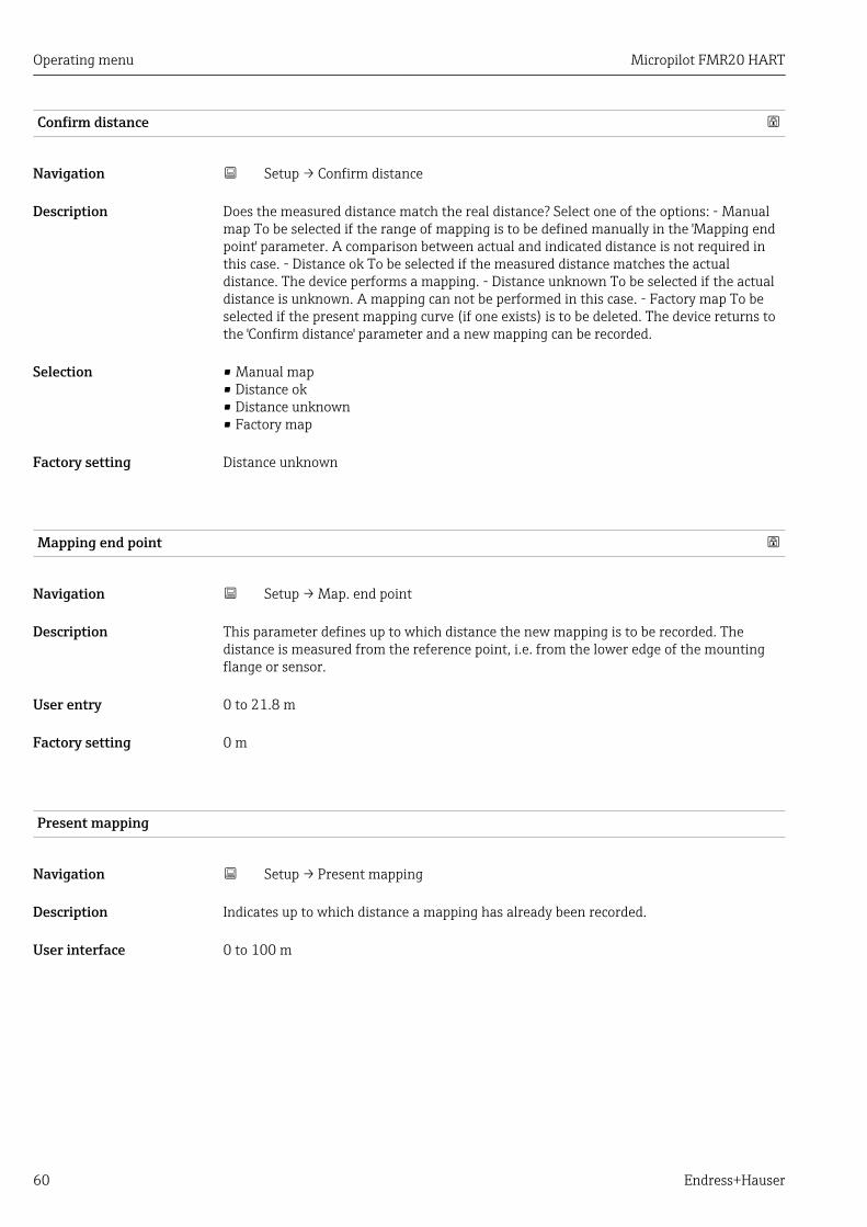
Operating menu Micropilot FMR20 HART
60 Endress+Hauser
Confirm distance
Navigation Setup → Confirm distance
Description Does the measured distance match the real distance? Select one of the options: - Manualmap To be selected if the range of mapping is to be defined manually in the 'Mapping endpoint' parameter. A comparison between actual and indicated distance is not required inthis case. - Distance ok To be selected if the measured distance matches the actualdistance. The device performs a mapping. - Distance unknown To be selected if the actualdistance is unknown. A mapping can not be performed in this case. - Factory map To beselected if the present mapping curve (if one exists) is to be deleted. The device returns tothe 'Confirm distance' parameter and a new mapping can be recorded.
Selection • Manual map• Distance ok• Distance unknown• Factory map
Factory setting Distance unknown
Mapping end point
Navigation Setup → Map. end point
Description This parameter defines up to which distance the new mapping is to be recorded. Thedistance is measured from the reference point, i.e. from the lower edge of the mountingflange or sensor.
User entry 0 to 21.8 m
Factory setting 0 m
Present mapping
Navigation Setup → Present mapping
Description Indicates up to which distance a mapping has already been recorded.
User interface 0 to 100 m
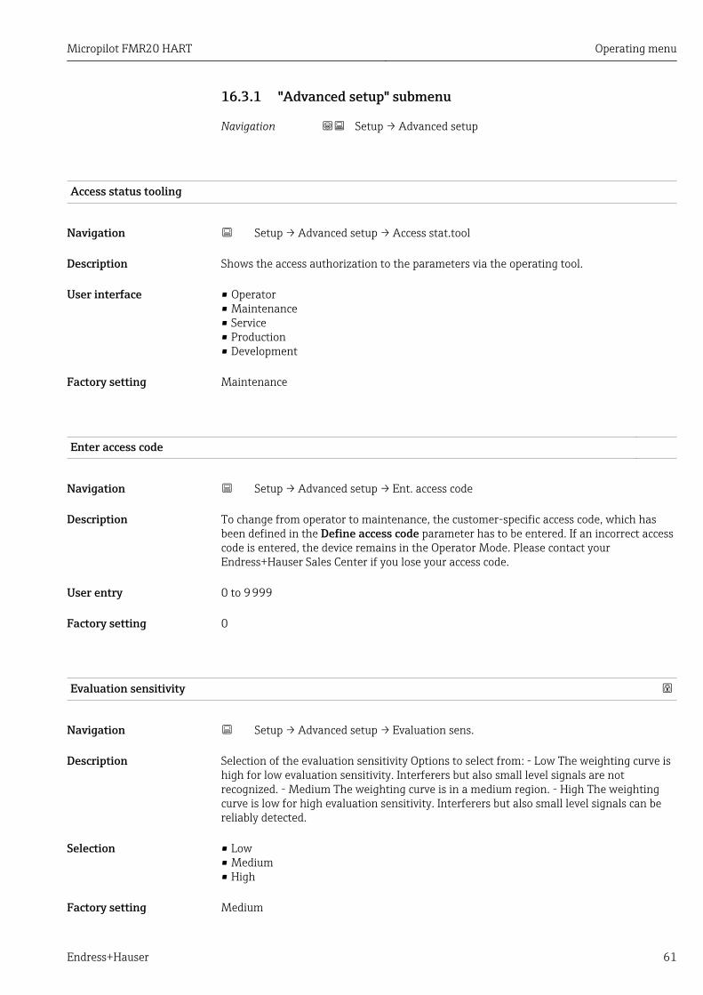
Micropilot FMR20 HART Operating menu
Endress+Hauser 61
16.3.1 "Advanced setup" submenu
Navigation Setup → Advanced setup
Access status tooling
Navigation Setup → Advanced setup → Access stat.tool
Description Shows the access authorization to the parameters via the operating tool.
User interface • Operator• Maintenance• Service• Production• Development
Factory setting Maintenance
Enter access code
Navigation Setup → Advanced setup → Ent. access code
Description To change from operator to maintenance, the customer-specific access code, which hasbeen defined in the Define access code parameter has to be entered. If an incorrect accesscode is entered, the device remains in the Operator Mode. Please contact yourEndress+Hauser Sales Center if you lose your access code.
User entry 0 to 9 999
Factory setting 0
Evaluation sensitivity
Navigation Setup → Advanced setup → Evaluation sens.
Description Selection of the evaluation sensitivity Options to select from: - Low The weighting curve ishigh for low evaluation sensitivity. Interferers but also small level signals are notrecognized. - Medium The weighting curve is in a medium region. - High The weightingcurve is low for high evaluation sensitivity. Interferers but also small level signals can bereliably detected.
Selection • Low• Medium• High
Factory setting Medium

Operating menu Micropilot FMR20 HART
62 Endress+Hauser
Changing velocity
Navigation Setup → Advanced setup → Changing vel.
Description Selection of the expected draining or filling speed of the measured level.
Selection • Slow <10 cm (0,4 in)/min• Standard <1 m (40 in)/min• Fast >1 m (40 in)/min• No filter / test
Factory setting Standard <1 m (40 in)/min
First Echo sensitivity
Navigation Setup → Advanced setup → First Echo sens.
Description This parameter describes the band for First Echo evaluation. Is measured / calculateddown from the peak of the current level echo. Options to select from: - Low The band forthe first echo evaluation is very narrow. The evaluation stays longer at the found echorespectively does not jump to the next Echo or distortion signal. - Medium The band forthe first echo evaluation has an average width. - High The band for the first echoevaluation is broad. The evaluation jumps earlier to the next echo or distortion signal.
Selection • Low• Medium• High
Factory setting Medium
Output mode
Navigation Setup → Advanced setup → Output mode
Description Select output mode between: Ullage = The remaining space in the tank or silo is indicated.or Level linearized = The level is indicated (more precisely: the linearized value if alinearization has been activated).
Selection • Ullage• Level linearized
Factory setting Level linearized

Micropilot FMR20 HART Operating menu
Endress+Hauser 63
Blocking distance
Navigation Setup → Advanced setup → Blocking dist.
Description Specify blocking distance (BD). No signals are evaluated within the blocking distance.Therefore, BD can be used to suppress interference signals in the vicinity of the antenna.Note: The measuring range should not overlap with the blocking distance.
User entry 0.0 to 20 m
Factory setting By default an automatic Blocking distance of at least 0.1 m (0.33 ft) is preset. However itcan be manually overwritten (even 0 m (0 ft) is allowed.Automatic calculation of the Blocking distance = Empty calibration - Full calibration -0.2 m (0.656 ft).The Blocking distance parameter is recalculated according to this formula every time anew value is entered into the Empty calibration parameter or Full calibration parameter.If this calculation results in a value <0.1 m (0.33 ft), the blocking distance of0.1 m (0.33 ft) is used instead.
Level correction
Navigation Setup → Advanced setup → Level correction
Description The measured level is corrected by this value to compensate for a constant level error.Level correction > 0: The level is increased by this value. Level correction < 0: The level isdecreased by this value.
User entry –25 to 25 m
Factory setting 0.0 m
Evaluation distance
Navigation Setup → Advanced setup → Evaluation dist.
Description Extended signal search area. Is generally greater than the empty distance. If the signal isfound below the empty distance, '0' (empty) is indicated as measured value. Only forsignals, detected below the 'Evaluation distance', the error 'Echo Lost' is issued. e.g. flowmeasurement in overflow weirs.
User entry 0 to 21.8 m
Factory setting 21.8 m

Operating menu Micropilot FMR20 HART
64 Endress+Hauser
Linearization type
Navigation Setup → Advanced setup → Lineariz. type
Description Linearization typesMeaning of the options:• None:
The level is transmitted in the level unit without linearization.• Table:
The relationship between the measured level L and the output value(volume/flow/weight) is given by a linearization table consisting of up to 32 pairs of values "level -volume" or "level - flow"or "level - weight", respectively.
• Remark:To create / modify a linearization table please open the linearization module in DTM
Selection • None• Table
Factory setting None
Level linearized
Navigation Setup → Advanced setup → Level linearized
Description Currently measured level.
User interface Signed floating-point number

Micropilot FMR20 HART Operating menu
Endress+Hauser 65
"Safety settings" submenu
Navigation Setup → Advanced setup → Safety sett.
Delay time echo lost
Navigation Setup → Advanced setup → Safety sett. → Delay echo lost
Description Define the delay time in the case of an echo loss. After an echo loss, the device waits forthe time specified in this parameter before reacting as specified in the Diagnostic echo lostparameter. This helps to avoid interruptions of the measurement by short-terminterferences.
User entry 0 to 600 s
Factory setting 300 s
Diagnostics echo lost
Navigation Setup → Advanced setup → Safety sett. → Diagn. echo lost
Description At this parameter it can be set if in case of a lost echo a warning or an alarm is issued.
Selection • Warning• Alarm
Factory setting Warning

Operating menu Micropilot FMR20 HART
66 Endress+Hauser
"Current output" submenu
Navigation Setup → Advanced setup → Curr.output
Output current
Navigation Setup → Advanced setup → Curr.output → Output curr.
Description Shows the actual calculated value of the output current.
User interface 3.59 to 22.5 mA
Damping output
Navigation Setup → Advanced setup → Curr.output → Damping out.
Description Define time constant τ for the damping of the output current. Fluctuations of themeasured value affect the output current with an exponential delay, the time constant τ ofwhich is defined in this parameter. With a small time constant the output reactsimmediately to changes of the measrued value. With a big time constant the reaction ofthe output is more delayed. For τ = 0 there is no damping.
User entry 0.0 to 300 s
Factory setting 1.0 s
Turn down
Navigation Setup → Advanced setup → Curr.output → Turn down
Description Using the turn down functionality it is possible to map a section of the measuring range tothe total range of the output current (4-20mA). The section is defined by the '4 mA value'and '20 mA value' parameters. Without the turn down, the complete measuring range (0to 100%) is mapped to the current output (4 to 20mA).
Selection • Off• On
Factory setting Off

Micropilot FMR20 HART Operating menu
Endress+Hauser 67
4 mA value
Navigation Setup → Advanced setup → Curr.output → 4 mA value
Description Value for 4-mA at 'Turn down parameter' = On Using the turn down functionality it ispossible to map a section of the measuring range to the total range of the output current(4-20mA). The section is defined by the '4 mA value' and '20 mA value' parameters.Without the turn down, the complete measuring range (0 to 100%) is mapped to thecurrent output (4 to 20mA). Note: If '20 mA value' is smaller than '4 mA value', the currentoutput is inverted, which means that an increase of the process variable results in adecrease of the output current.
User entry Signed floating-point number
Factory setting 0 m
20 mA value
Navigation Setup → Advanced setup → Curr.output → 20 mA value
Description Value for 20-mA at 'Turn down' parameter = On Using the turn down functionality it ispossible to map a section of the measuring range to the total range of the output current(4-20mA). The section is defined by the '4 mA value' and '20 mA value' parameters.Without the turn down, the complete measuring range (0 to 100%) is mapped to thecurrent output (4 to 20mA). Note: If '20 mA value' is smaller than '4 mA value', the currentoutput is inverted, which means that an increase of the process variable results in adecrease of the output current.
User entry Signed floating-point number
Factory setting 20 m
Trim
Navigation Setup → Advanced setup → Curr.output → Trim
Description Select action for the recalibration of the current output. The trim can be used tocompensate a drift of the current output (which might be caused by very long cables or bya connected Ex barrier, for example). Steps of the trim: 1. Select 'Trim' = 4 mA. 2. Measurethe output current with a gauged multimeter. If it is not equal to 4 mA: Enter measuredvalue in the 'Trim value low' parameter. 3. Select 'Trim' = 20 mA. 4. Measure the outputcurrent with a gauged multimeter. If it is not equal to 20 mA: Enter the measured currentinto the 'Trim value high' parameter. 5. Select 'Trim' = Calculate. The device calculates thenew scaling of the output current and stores it in the RAM.

Operating menu Micropilot FMR20 HART
68 Endress+Hauser
Selection • Off• 4 mA• 20 mA• Calculate• Reset
Factory setting Off
Trim value high
Navigation Setup → Advanced setup → Curr.output → Trim value high
Description Enter upper measured value for the trim (around 20 mA). After this value has beenentered: Select 'Trim' = Calculate. This initiates the recalibration of the current output.
User entry 18.0 to 22.0 mA
Factory setting 20.0 mA
Trim value low
Navigation Setup → Advanced setup → Curr.output → Trim value low
Description Enter lower measured value for the trim (around 4 mA). After this value has been entered:Select 'Trim' = Calculate. This initiates the recalibration of the current output.
User entry 3.0 to 5.0 mA
Factory setting 4.0 mA
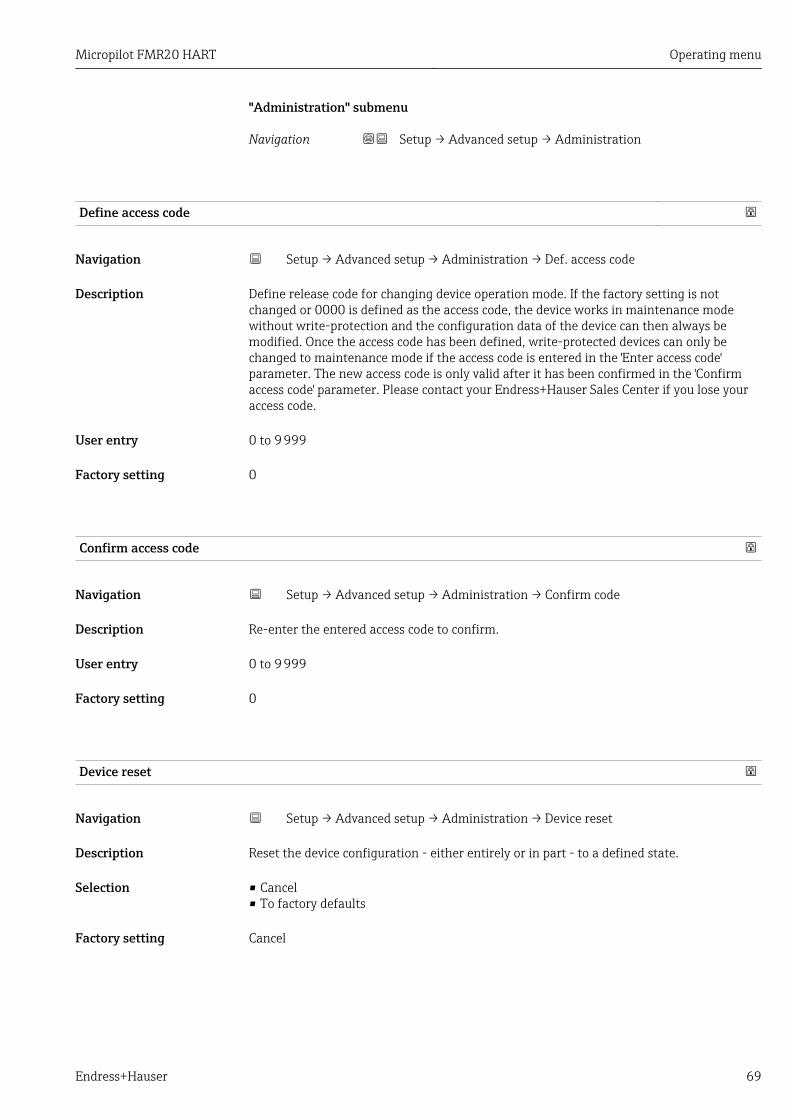
Micropilot FMR20 HART Operating menu
Endress+Hauser 69
"Administration" submenu
Navigation Setup → Advanced setup → Administration
Define access code
Navigation Setup → Advanced setup → Administration → Def. access code
Description Define release code for changing device operation mode. If the factory setting is notchanged or 0000 is defined as the access code, the device works in maintenance modewithout write-protection and the configuration data of the device can then always bemodified. Once the access code has been defined, write-protected devices can only bechanged to maintenance mode if the access code is entered in the 'Enter access code'parameter. The new access code is only valid after it has been confirmed in the 'Confirmaccess code' parameter. Please contact your Endress+Hauser Sales Center if you lose youraccess code.
User entry 0 to 9 999
Factory setting 0
Confirm access code
Navigation Setup → Advanced setup → Administration → Confirm code
Description Re-enter the entered access code to confirm.
User entry 0 to 9 999
Factory setting 0
Device reset
Navigation Setup → Advanced setup → Administration → Device reset
Description Reset the device configuration - either entirely or in part - to a defined state.
Selection • Cancel• To factory defaults
Factory setting Cancel

Operating menu Micropilot FMR20 HART
70 Endress+Hauser
Free field special
Navigation Setup → Advanced setup → Administration → Free field spec.
Description Switch the free field option on or off. This parameter can be switched on for free fieldapplications (e.g. below bridges). Caution: The customer map (if one exists) is reset to thefactory map!.
Selection • Off• On
Factory setting Off

Micropilot FMR20 HART Operating menu
Endress+Hauser 71
16.3.2 "Communication" submenu
Navigation Setup → Communication
HART short tag
Navigation Setup → Communication → HART short tag
Description Short description of the measuring point
User entry Max. 8 characters: A ... Z, 0 ... 9 and some special characters (for example, punctuationmarks, @,%)
Factory setting SHORTTAG
HART address
Navigation Setup → Communication → HART address
User entry 0 to 63
Factory setting 0
No. of preambles
Navigation Setup → Communication → No. of preambles
Description Defines the number o preambles in the HART telegram.
User entry 5 to 20
Factory setting 5
Device type
Navigation Setup → Communication → Device type
Description Shows the device type with which the measuring device is registered with the HARTCommunication Foundation.
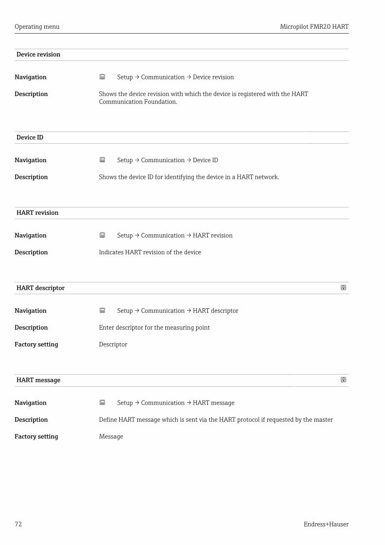
Operating menu Micropilot FMR20 HART
72 Endress+Hauser
Device revision
Navigation Setup → Communication → Device revision
Description Shows the device revision with which the device is registered with the HARTCommunication Foundation.
Device ID
Navigation Setup → Communication → Device ID
Description Shows the device ID for identifying the device in a HART network.
HART revision
Navigation Setup → Communication → HART revision
Description Indicates HART revision of the device
HART descriptor
Navigation Setup → Communication → HART descriptor
Description Enter descriptor for the measuring point
Factory setting Descriptor
HART message
Navigation Setup → Communication → HART message
Description Define HART message which is sent via the HART protocol if requested by the master
Factory setting Message

Micropilot FMR20 HART Operating menu
Endress+Hauser 73
Hardware revision
Navigation Setup → Communication → Hardware rev.
Description Indicates hardware revision of the device
Software revision
Navigation Setup → Communication → Software rev.
Description Indicates software revision of the device
HART date code
Navigation Setup → Communication → HART date code
Description Enter date of the last configuration change
Additional information Date format: YYYY-MM-DD
Level linearized (PV)
Navigation Setup → Communication → Level lin. (PV)
Description Displays linearized level
User interface Signed floating-point number
Factory setting 0 m
Additional information The unit is defined by the Unit after linearization parameter
Distance (SV)
Navigation Setup → Communication → Distance (SV)
User interface Signed floating-point number
Factory setting 0 m

Operating menu Micropilot FMR20 HART
74 Endress+Hauser
Relative echo amplitude (TV)
Navigation Setup → Communication → Rel.echoampl(TV)
User interface Signed floating-point number
Factory setting 0 dB
Temperature (QV)
Navigation Setup → Communication → Temperature (QV)
User interface Signed floating-point number
Factory setting –273.15 °C
"Bluetooth configuration" submenu
Navigation Setup → Communication → Bluetooth conf.
Bluetooth mode
Navigation Setup → Communication → Bluetooth conf. → Bluetooth mode
Description Enable or disable Bluetooth function.. Remark: Switching to position 'Off' will disableremote access via the app with immediate effect. To re-establish a Bluetooth connectionvia the app: Please follow the advices in the manual.
Selection • Off• On
Factory setting On
Micropilot FMR20 HART Operating menu
Endress+Hauser 75
16.4 "Diagnostics" submenu
Navigation Diagnostics
Actual diagnostics
Navigation Diagnostics → Actual diagnos.
Description Displays current diagnostic message. If several messages are active at the same time, themessages with the highest priority is displayed.
Previous diagnostics
Navigation Diagnostics → Prev.diagnostics
Description Displays the last diagnostic message, with its diagnostic information, which has beenactive before the current message. The condition displayed may still apply.
Delete previous diagnostic
Navigation Diagnostics → Del. prev. diag.
Description Delete previous diagnostic message? It is possible that the diagnostic message remainsvalid.
Selection • No• Yes
Factory setting No
Signal quality
Navigation Diagnostics → Signal quality
Description Displays the signal quality of the level echo. Meaning of the display options - Strong: Theevaluated echo exceeds the threshold by at least 10 dB. - Medium: The evaluated echoexceeds the threshold by at least 5 dB. - Weak: The evaluated echo exceeds the thresholdby less than 5 dB. - No signal: The device does not find an usable echo. The signal qualityindicated in this parameter always refers to the currently evaluated echo, either the levelecho or the tank bottom echo. In case of a lost echo ('Signal quality' = No signal) the devicegenerates the following error message: 'Diagnostic echo lost' = Warning (factory setting) orAlarm, if the other option has been selected in 'Diagnostic echo lost'.

Operating menu Micropilot FMR20 HART
76 Endress+Hauser
User interface • Strong• Medium• Weak• No signal

Micropilot FMR20 HART Operating menu
Endress+Hauser 77
16.4.1 "Device information" submenu
Navigation Diagnostics → Device info
Device name
Navigation Diagnostics → Device info → Device name
Description Shows the name of the transmitter.
Factory setting Micropilot FMR20
Firmware version
Navigation Diagnostics → Device info → Firmware version
Description Shows the device firmware version installed.
Extended order code 1
Navigation Diagnostics → Device info → Ext. order cd. 1
Description Shows the 1st part of the extended order code.
Extended order code 2
Navigation Diagnostics → Device info → Ext. order cd. 2
Description Shows the 2nd part of the extended order code.
Extended order code 3
Navigation Diagnostics → Device info → Ext. order cd. 3
Description Shows the 3rd part of the extended order code.

Operating menu Micropilot FMR20 HART
78 Endress+Hauser
Order code
Navigation Diagnostics → Device info → Order code
Description Shows the device order code.
Serial number
Navigation Diagnostics → Device info → Serial number
Description Shows the serial number of the measuring device.
ENP version
Navigation Diagnostics → Device info → ENP version
Description Shows the version of the electronic nameplate (ENP).

Micropilot FMR20 HART Operating menu
Endress+Hauser 79
16.4.2 "Simulation" submenu
Navigation Diagnostics → Simulation
Simulation
Navigation Diagnostics → Simulation → Simulation
Description Select process variable to be simulated. The Simulation is used to simulate specificmeasuring values or other conditions. This helps to check the correct configuration of thedevice and connected control units.
Selection • Off• Current output• Distance
Factory setting Off
Value current output
Navigation Diagnostics → Simulation → Value curr.out 1
Description Defines the value of the simulated output current.
User entry 3.59 to 22.5 mA
Factory setting 3.59 mA
Process variable value
Navigation Diagnostics → Simulation → Proc. var. value
Description Value of the simulated process variable. Downstream measured value processing and thesignal output use this simulation value. In this way, users can verify whether themeasuring device has been configured correctly.
User entry 0 to 21.8 m
Factory setting 0 m

Index
80 Endress+Hauser
Index
0 … 94 mA value (Parameter) . . . . . . . . . . . . . . . . . . . . . . 6720 mA value (Parameter) . . . . . . . . . . . . . . . . . . . . . 67
AAccess status tooling (Parameter) . . . . . . . . . . . . . . . 61Accessories
Communication-specific . . . . . . . . . . . . . . . . . . . . 48Device-specific . . . . . . . . . . . . . . . . . . . . . . . . . . . 45
flange . . . . . . . . . . . . . . . . . . . . . . . . . . . . . . . 46Device-specific accessories - cantilever pivotally . . . 47Overview . . . . . . . . . . . . . . . . . . . . . . . . . . . . . . . 45Service-specific . . . . . . . . . . . . . . . . . . . . . . . . . . . 48System components . . . . . . . . . . . . . . . . . . . . . . . 48
Actual diagnostics (Parameter) . . . . . . . . . . . . . . . . . 75Administration (Submenu) . . . . . . . . . . . . . . . . . . . . 69Advanced setup (Submenu) . . . . . . . . . . . . . . . . . . . . 61Application . . . . . . . . . . . . . . . . . . . . . . . . . . . . . . . . . 7
BBlocking distance (Parameter) . . . . . . . . . . . . . . . . . . 63Bluetooth configuration (Submenu) . . . . . . . . . . . . . . 74Bluetooth mode (Parameter) . . . . . . . . . . . . . . . . . . . 74Bluetooth® wireless technology . . . . . . . . . . . . . . . . . 24
CChanging velocity (Parameter) . . . . . . . . . . . . . . . . . . 62Cleaning . . . . . . . . . . . . . . . . . . . . . . . . . . . . . . . . . . 43Communication (Submenu) . . . . . . . . . . . . . . . . . . . . 71Configuration of a flow measurement . . . . . . . . . . . . 36Configuration of a level measurement . . . . . . . . . . . . 34Configuring flow measurement . . . . . . . . . . . . . . . . . 36Configuring level measurement . . . . . . . . . . . . . . . . . 34Confirm access code (Parameter) . . . . . . . . . . . . . . . . 69Confirm distance (Parameter) . . . . . . . . . . . . . . . . . . 60Current output (Submenu) . . . . . . . . . . . . . . . . . . . . . 66
DDamping output (Parameter) . . . . . . . . . . . . . . . . . . . 66DD . . . . . . . . . . . . . . . . . . . . . . . . . . . . . . . . . . . . . . 30Define access code (Parameter) . . . . . . . . . . . . . . . . . 69Delay time echo lost (Parameter) . . . . . . . . . . . . . . . . 65Delete previous diagnostic (Parameter) . . . . . . . . . . . 75Designated use . . . . . . . . . . . . . . . . . . . . . . . . . . . . . . 7Device description files . . . . . . . . . . . . . . . . . . . . . . . 30Device ID (Parameter) . . . . . . . . . . . . . . . . . . . . . . . . 72Device information (Submenu) . . . . . . . . . . . . . . . . . . 77Device name (Parameter) . . . . . . . . . . . . . . . . . . . . . 77Device replacement . . . . . . . . . . . . . . . . . . . . . . . . . . 44Device reset (Parameter) . . . . . . . . . . . . . . . . . . . . . . 69Device revision (Parameter) . . . . . . . . . . . . . . . . . . . . 72Device tag (Parameter) . . . . . . . . . . . . . . . . . . . . . . . 58Device type (Parameter) . . . . . . . . . . . . . . . . . . . . . . 71Diagnostic event
In the operating tool . . . . . . . . . . . . . . . . . . . . . . . 42Diagnostic event in the RIA15 . . . . . . . . . . . . . . . . . . 42Diagnostics (Submenu) . . . . . . . . . . . . . . . . . . . . . . . 75
Diagnostics echo lost (Parameter) . . . . . . . . . . . . . . . 65Disposal . . . . . . . . . . . . . . . . . . . . . . . . . . . . . . . . . . 44Distance (Parameter) . . . . . . . . . . . . . . . . . . . . . . . . . 59Distance (SV) (Parameter) . . . . . . . . . . . . . . . . . . . . . 73Distance unit (Parameter) . . . . . . . . . . . . . . . . . . . . . 58
EEmpty calibration (Parameter) . . . . . . . . . . . . . . . . . . 58ENP version (Parameter) . . . . . . . . . . . . . . . . . . . . . . 78Enter access code (Parameter) . . . . . . . . . . . . . . . . . . 61Evaluation distance (Parameter) . . . . . . . . . . . . . . . . 63Evaluation sensitivity (Parameter) . . . . . . . . . . . . . . . 61Extended order code 1 (Parameter) . . . . . . . . . . . . . . 77Extended order code 2 (Parameter) . . . . . . . . . . . . . . 77Extended order code 3 (Parameter) . . . . . . . . . . . . . . 77Exterior cleaning . . . . . . . . . . . . . . . . . . . . . . . . . . . . 43
FField of application
Residual risks . . . . . . . . . . . . . . . . . . . . . . . . . . . . . 7Firmware version (Parameter) . . . . . . . . . . . . . . . . . . 77First Echo sensitivity (Parameter) . . . . . . . . . . . . . . . 62Free field special (Parameter) . . . . . . . . . . . . . . . . . . 70Full calibration (Parameter) . . . . . . . . . . . . . . . . . . . . 58FV (HART variable) . . . . . . . . . . . . . . . . . . . . . . . . . . 30
HHardware revision (Parameter) . . . . . . . . . . . . . . . . . 73HART address (Parameter) . . . . . . . . . . . . . . . . . . . . 71HART date code (Parameter) . . . . . . . . . . . . . . . . . . . 73HART descriptor (Parameter) . . . . . . . . . . . . . . . . . . . 72HART integration . . . . . . . . . . . . . . . . . . . . . . . . . . . 30HART message (Parameter) . . . . . . . . . . . . . . . . . . . . 72HART protocol . . . . . . . . . . . . . . . . . . . . . . . . . . . . . 24HART revision (Parameter) . . . . . . . . . . . . . . . . . . . . 72HART short tag (Parameter) . . . . . . . . . . . . . . . . . . . 71HART variables . . . . . . . . . . . . . . . . . . . . . . . . . . . . . 30
LLevel (Parameter) . . . . . . . . . . . . . . . . . . . . . . . . . . . 59Level correction (Parameter) . . . . . . . . . . . . . . . . . . . 63Level linearized (Parameter) . . . . . . . . . . . . . . . . . . . 64Level linearized (PV) (Parameter) . . . . . . . . . . . . . . . 73Linearization type (Parameter) . . . . . . . . . . . . . . . . . 64
MMaintenance . . . . . . . . . . . . . . . . . . . . . . . . . . . . . . . 43Mapping end point (Parameter) . . . . . . . . . . . . . . . . . 60Media . . . . . . . . . . . . . . . . . . . . . . . . . . . . . . . . . . . . . 7Menu
Setup . . . . . . . . . . . . . . . . . . . . . . . . . . . . . . . . . . 58
NNo. of preambles (Parameter) . . . . . . . . . . . . . . . . . . 71
OOperational safety . . . . . . . . . . . . . . . . . . . . . . . . . . . . 8
Index
Endress+Hauser 81
Order code (Parameter) . . . . . . . . . . . . . . . . . . . . . . . 78Output current (Parameter) . . . . . . . . . . . . . . . . . . . . 66Output mode (Parameter) . . . . . . . . . . . . . . . . . . . . . 62
PPost-connection check . . . . . . . . . . . . . . . . . . . . . . . . 23Present mapping (Parameter) . . . . . . . . . . . . . . . . . . 60Previous diagnostics (Parameter) . . . . . . . . . . . . . . . . 75Process variable value (Parameter) . . . . . . . . . . . . . . . 79Product safety . . . . . . . . . . . . . . . . . . . . . . . . . . . . . . . 8PV (HART variable) . . . . . . . . . . . . . . . . . . . . . . . . . . 30
RRelative echo amplitude (TV) (Parameter) . . . . . . . . . 74Repair concept . . . . . . . . . . . . . . . . . . . . . . . . . . . . . 44Replacing a device . . . . . . . . . . . . . . . . . . . . . . . . . . . 44Requirements for personnel . . . . . . . . . . . . . . . . . . . . . 7Return . . . . . . . . . . . . . . . . . . . . . . . . . . . . . . . . . . . 44
SSafety instructions
Basic . . . . . . . . . . . . . . . . . . . . . . . . . . . . . . . . . . . 7Safety Instructions (XA) . . . . . . . . . . . . . . . . . . . . . . . 10Safety settings (Submenu) . . . . . . . . . . . . . . . . . . . . . 65Serial number (Parameter) . . . . . . . . . . . . . . . . . . . . 78Setup (Menu) . . . . . . . . . . . . . . . . . . . . . . . . . . . . . . 58Signal quality (Parameter) . . . . . . . . . . . . . . . . . . 59, 75Simulation (Parameter) . . . . . . . . . . . . . . . . . . . . . . . 79Simulation (Submenu) . . . . . . . . . . . . . . . . . . . . . . . . 79Software revision (Parameter) . . . . . . . . . . . . . . . . . . 73Submenu
Administration . . . . . . . . . . . . . . . . . . . . . . . . . . . 69Advanced setup . . . . . . . . . . . . . . . . . . . . . . . . . . 61Bluetooth configuration . . . . . . . . . . . . . . . . . . . . 74Communication . . . . . . . . . . . . . . . . . . . . . . . . . . 71Current output . . . . . . . . . . . . . . . . . . . . . . . . . . . 66Device information . . . . . . . . . . . . . . . . . . . . . . . . 77Diagnostics . . . . . . . . . . . . . . . . . . . . . . . . . . . . . 75Safety settings . . . . . . . . . . . . . . . . . . . . . . . . . . . 65Simulation . . . . . . . . . . . . . . . . . . . . . . . . . . . . . . 79
SV (HART variable) . . . . . . . . . . . . . . . . . . . . . . . . . . 30System components . . . . . . . . . . . . . . . . . . . . . . . . . . 48
TTemperature (QV) (Parameter) . . . . . . . . . . . . . . . . . 74Trim (Parameter) . . . . . . . . . . . . . . . . . . . . . . . . . . . 67Trim value high (Parameter) . . . . . . . . . . . . . . . . . . . 68Trim value low (Parameter) . . . . . . . . . . . . . . . . . . . . 68Troubleshooting . . . . . . . . . . . . . . . . . . . . . . . . . . . . 41Turn down (Parameter) . . . . . . . . . . . . . . . . . . . . . . . 66TV (HART variable) . . . . . . . . . . . . . . . . . . . . . . . . . . 30
UUse of the measuring devices
Borderline cases . . . . . . . . . . . . . . . . . . . . . . . . . . . 7Incorrect use . . . . . . . . . . . . . . . . . . . . . . . . . . . . . 7
Using measuring devicesee Designated use
VValue current output 1 (Parameter) . . . . . . . . . . . . . . 79
WWorkplace safety . . . . . . . . . . . . . . . . . . . . . . . . . . . . 8


www.addresses.endress.com