Embed Size (px)
Citation preview
Microscale Hydrogen Diffusion Flames
V.R. Lecoustre, P.B. SunderlandDept. of Fire Protection Engineering,
University of Maryland,College Park, MD 20742, USA
B.H. ChaoDept. of Mechanical Engineering,
University of Hawaii,Honolulu, HI 96822, USA
R.L. AxelbaumDept. of Energy, Environmental and Chemical Engineering,
Washington University,St. Louis, MO 63130, USA
Submitted to: 33rd Combustion Symposium (Beijing)
Submission Date: January 10, 2010
Corresponding Author:Peter B. SunderlandDept. of Fire Protection EngineeringUniversity of Maryland3104 J.M. Patterson BuildingCollege Park MD 20742 USAtel (301) 405-3095fax (301) [email protected]
Colloquium: Laminar Flames
Alternate Colloquium: Reaction Kinetics
Total length: Using method 1
Word equivalent: 5327 (Total); limit 5800Main text: 3277References: 297Table 1: 46Table 2: 129Figures: 1581, as follows. Figure 1: 291; Figure 2: 320; Figure 3: 173; Figure 4: 314; Figure 5: 314; Figure 6: 169.
Affirmation to pay color reproduction charges if applicable: affirmed.
1
Abstract
Microscale hydrogen diffusion flames were studied experimentally and numerically. The
experiments involved laminar jet diffusion flames with hydrogen discharging downward from
stainless steel micro-tube burners with inside diameters of 0.15 mm. At their quenching limits
these flames had heat release rates of 0.46 and 0.25 W (hydrogen flow rates of 3.9 and 2.1 g/s)
in air and oxygen, respectively. These are apparently the weakest flames ever observed. Because
the flames were primarily diffusion controlled and hemispherical, they were modeled
numerically as spherical diffusion flames with detailed chemistry and transport. The modeling
results confirmed the measured quenching limits, identified these as being due to kinetic
extinction, and revealed high rates of reactant leakage near extinction. Different combustion
regimes were investigated by varying the hydrogen flow rate and spherical burner size, and the
main reactions contributing to the heat release rate were identified. The numerical study exhibits
the existence of a premixed flame regime as predicted by Liñán’s analysis of counterflow
diffusion flames.
Keywords: Kinetic extinction; laminar diffusion flames; oxygen-enhanced combustion;
quenching limits.
1. Introduction
This study is motivated by an a concern of fire hazards associated with small leaks in hydrogen
systems and the use of microcombustors for power generation. Butler et al. [1] examined the fire
hazards of small hydrogen leaks. They observed quenching limits of diffusion flames on small
tube burners and found the quenching mass flow rates for hydrogen to be about an order of
magnitude lower than those for methane and propane. At the quenching limits the flame height
was comparable to the quenching distance for premixed hydrogen flames, in agreement with
2
other studies [2,3]. Significantly smaller quenching limits for hydrogen were observed for
leaking compression fittings as well [1]. These hazards are now acknowledged in an SAE
recommended practice [4], which requires that hydrogen vehicles not have localized leaks in
excess of the measured quenching limits of Ref. [1].
Quenching limits are caused by kinetic extinction, which occurs at high scalar dissipation
rates (low Damköhler numbers) and may occur without external losses (i.e., losses other than
chemical enthalpy loss). Kinetic extinction phenomena affect the anchoring and stability of
practical flames and have been the subject of many studies, e.g., Refs. [5-7]. This is contrary to
radiative extinction [8], which occurs at high Damköhler numbers because of excessive radiative
heat loss and to date has only been conclusively observed in microgravity. Note that an increase
in flow rate decreases scalar dissipation rates in spherical diffusion flames but increases them in
spherical diffusion flames.
Microcombustors have potential advantages over batteries in terms of power generation
per unit volume and energy storage per unit mass [9]. Recent developments in micro-electro-
mechanical systems (MEMS) have enabled microcombustors with dimensions on the order of
1 mm [9]. The ability to burn weak but stable flames is important in the design of
microcombustors and it also may allow flames to serve as permanent pilots, thereby replacing
electric ignitors.
Several studies have examined flames that are among the weakest ever observed. Ronney
et al. [10] observed the burning of microgravity premixed flame balls during the STS-83 Space
Shuttle mission, with heat release rates as low as 0.5 – 1 W. Weak propane flames anchored on a
0.1 mm tube were found to have heat release rates as low as 1 W [2]. Nakamura et al. [3]
numerically predicted the existence of methane diffusion flames as weak as 0.5 W. The weakest
3
flame to date was reported by Butler et al. [1], which was a gas jet flame fueled by hydrogen
flowing downward into air from a micro-tube with inside diameter of 0.15 mm. This flame had a
heat release rate of 0.49 W and is further considered below.
Thus motivated, the objectives of this work are to experimentally observe microscale
hydrogen flames at their quenching limits in air and in oxygen, and to numerically investigate the
flame structure of spherical microflames to understand the mechanism of extinction in these
flames. The numerical code developed is a one-dimensional spherical code with detailed
chemistry and transport.
2. Experimental Methods and Results
The experiments involved two hydrogen diffusion flames, one burning in quiescent air and the
other in nearly quiescent oxygen. The burner was a stainless steel hypodermic tube with an
inside diameter of 0.15 mm and an outside diameter of 0.30 mm. Tests with platinum tubes of
similar dimensions had nearly identical quenching limits, ruling out significant effects of surface
reactions. The hydrogen jets issued downward. Horizontal and upward-flowing orientations also
were studied and quenching limits were only slightly higher [1]. Hydrogen flow rates were
measured with a rotameter. A pure oxygen ambient was obtained by placing the burner tip
40 mm above a 100 mm diameter supply of O2 flowing upward at 20 mm/s through a plenum
and a ceramic honeycomb flow straightener. There was no measurable change in the quenching
limit with changes in oxygen velocity.
The flames were not visible and hence were detected with a thermocouple 1 cm above the
burner tip. After ignition, the hydrogen flow rate was reduced slowly until each flame was
extinguished at its quenching limit. The images were recorded with a Nikon D100 camera at
4
ISO 200, f/1.4, and a shutter time of 30 s with room lights off. Additional experimental details
can be found in Butler et al. [1].
Color images of the two hydrogen flames at their quenching limits are shown in Fig. 1.
The test conditions for these flames are given in Table 1. The word “WE” on a U.S. dime is
included at flame scale to show that the flames are smaller than the smallest letters on U.S. coins.
The flames are hazy, suggesting distributed reaction zones rather than thin flame sheets.
The heat release rates associated with the mass flow rates are provided in Table 1. These
were obtained by assuming complete combustion of hydrogen and a lower heating value of
LHV = 120 kJ/g. Also included in Table 1 are the Reynolds, Froude, and Peclet numbers:
Re = u d / ; Fr = u2 / g d ; and Pe = ReD (lD / d) Sc , (1)
where u is the mean hydrogen velocity in the burner, d is the burner inside diameter, is
kinematic viscosity, g is the acceleration of gravity, lD is a characteristic diffusion length scale,
and Sc is the Schmidt number. Here lD is taken as 1 mm, and Sc is taken as 0.204 and 0.22 for
H2/air and H2/O2 flames, respectively [11]. The viscosity in Eq. (1) pertains to hydrogen at
laboratory pressure and temperature.
3. Numerical Methods
Although the flames are gas jets, their images (Fig. 1) suggest spherical symmetry near the
burner axis. The relatively high Froude numbers in Table 1 indicate that momentum dominates
over buoyancy in these two flames, while the low Peclet numbers indicate that diffusion
dominates over momentum. Nakamura et al. [3] numerically studied methane gas jet diffusion
flames on burners with diameters less than 1 mm and found the flames to be nearly
hemispherical for Pe < 5. Han et al. [12] observed and predicted the shapes of small hydrocarbon
jet flames, which they found to be only slightly affected by buoyancy and nearly hemispherical
5
owing to the comparable importance of streamwise diffusion and convection. Matta et al. [2]
reached similar conclusions for small propane flames. Cheng et al. [13] found that microjet
hydrogen diffusion flames with hydrogen issuing from tubes of 0.2 and 0.48 mm were
hemispherical near extinction.
The goal of the numerical effort is to understand the underlying mechanism for extinction
in micro-diffusion flames. Owing to this and the near spherical nature of the flames in Fig. 1, the
numerical modeling here is for spherically symmetric systems. The solver employed was
modified from the PREMIX [14] code. It solves conservation of mass, species, and energy at
steady state. The flow is assumed to be isobaric and laminar. Conventional finite difference
techniques with non-uniform mesh spacing were adopted to discretize the conservation
equations. The equations were then solved using Sandia TWOPNT [15], which adopts a
modified damped Newton’s method to solve boundary value problems. The diffusive and
convective terms were expressed by central and upwind difference formulas, respectively.
Chemical reaction rates, thermodynamic properties, and transport properties were evaluated by
CHEMKIN and the TRANSPORT library [16,17]. The hydrogen/oxygen/nitrogen chemistry was
extracted from GRI-Mech 3.0 [18], and included 67 reactions and 18 species. The key reactions
considered are listed in Table 2.
The boundary conditions were those of an adiabatic porous spherical burner [8,19]. The
inner boundary was assumed adiabatic in that a heat balance there equates conductive heating
from the gas with an increase in sensible enthalpy of hydrogen that was initially at 300 K. At the
burner surface, for each species mass diffusion is balanced with convective transport and, for H2,
with inflow. The outer boundary had a radius of 150 cm, a temperature of 300 K, and a
composition of either air or O2. For most of the flames considered here this simulated an infinite
6
boundary. Adaptive mesh point addition was used to ensure that the solution was grid
independent. Radiative heat losses were neglected because effects of radiation are small for
hydrogen flames, particularly extremely small ones [20].
Quenching limits were defined as the extinction states of the steady state flames. Each
flaming solution obtained from a specified hydrogen flow rate was used as the starting condition
for a new simulation with a decreased mass flow rate. Extinction was identified when a solution
showed no significant rise of temperature.
The local scalar dissipation rate was obtained from
χ = 2 α (dZ / dr)2 , (2)
where r is radius and α and Z are the local thermal diffusivity and mixture fraction. The mixture
fraction is defined as
, (3)
where Y is the local mass fraction, M is atomic weight, and each subscript denotes the element
considered. Local equivalence ratio was evaluated from
= (1 / Zst – 1) / (1 / Z – 1) , (4)
where the stoichiometric mixture fraction Zst is 0.029 for H2/air and 0.13 for H2/O2. The peak
temperature, Tf, with its radius, rf, and scalar dissipation rate χf, are used to denote flame
properties, although the present flames have broadened reaction zones. The local chemical heat
release rate, Qc, was determined by summing over all reactions, and was integrated over the
entire domain to obtain the total chemical heat release rate.
7
4. Numerical Results
Numerical investigations of quenching limits were performed for comparison with the
experimental results. These used a burner radius of 75 μm to match the radius of the
experimental burner. Numerical quenching limits were found to have hydrogen flow rates of
3.65 and 2.67 μg/s (i.e., heat release rates of 0.44 W and 0.32 W based on the lower heating
value of H2) for the H2/air and H2/O2 flames, respectively. The total heat release rates obtained by
numerical integration of Qc were about 3% lower than these values. The numerical quenching
limits are in reasonable agreement with the measurements of Table 1.
Details of the predicted H2/air flame just above the quenching limit are shown in Fig. 2 in
solid curves. This flame has a peak temperature of 1290 K, is located within 1.2 μm of the
burner, and has significant penetration of O2 to the burner surface. Conditions are fuel lean
across the entire domain, in agreement with Ref. [13], and = 0.05 at the peak temperature. The
main reaction contributing to the heat release rate is R84 (H2+OH→H+H2O). The next largest
contributors are R35, R46, and R45 (see Table 2), which involve H radical consumption and HO2
chemistry. There is also one significant endothermic reaction, the chain branching reaction R38,
which is the most important chain branching reaction for hydrogen combustion [23].
The possibility that the extensive leakage of oxygen in this flame arises from interference
from the burner was investigated by considering (in dashed curves in Fig. 2) the quenching limit
of a flame stabilized by a burner with radius of 1 μm. This yields YH2 = 1 and T = 300 K at the
burner surface because the high flow velocities prevent O2 from reaching the burner.
Nevertheless, extensive O2 penetration into the reaction region occurs. Comparing the two flames
reveals that the larger burner truncates the flame below a radius of 75 μm, but has little effect
elsewhere. Values of Tf, rf, and χf are similar for both flames. The small flames induce high Qc,
8
whose peaks increase from 3800 to 8000 W/cm3, when the burner is reduced from 75 μm to
1 μm. Reactions R46 and R35 have the highest peaks, but they occur at such small radii that R84
remains the dominant contributor to overall heat release. These high peaks involve the
consumption of H radical close to the burner, which are produced at greater radii, indicating the
importance of backward diffusion for H.
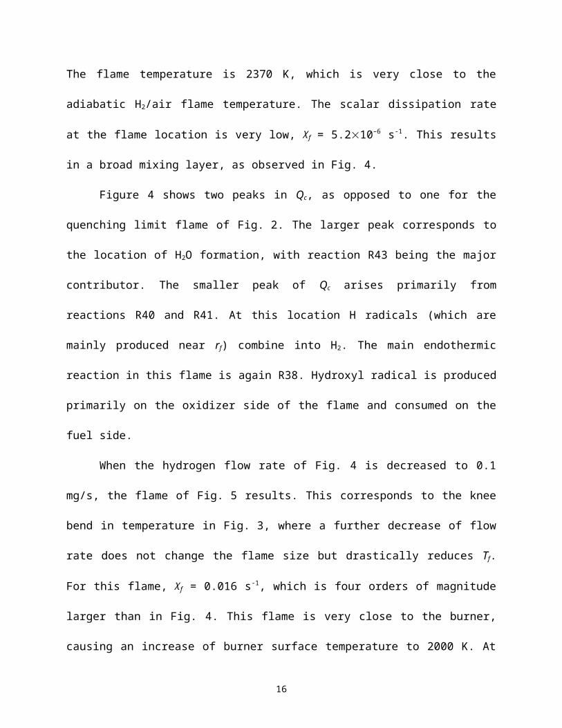
The impact of the H2 flow rate and burner radius were studied for many H2/air flames
near and above their quenching limits. Their effects on peak temperature and its location are
summarized in Fig. 3. At the highest hydrogen flow rates Tf and rf are independent of burner
diameter for all the burners considered. For the three larger burners, as flow rate decreases the
burner’s presence increases rf and reduces Tf and quenching occurs when rf approaches the
burner such that the reaction region attaches to the burner. For the smallest burner the burner
diameter has no effect on rf or Tf even at its quenching limit. Extinction is observed at a peak
temperature of about 1300 K regardless of burner diameter. Except near the quenching limits,
Fig. 3 shows that flame radius scales with 1.1, where is the mass flow rate.
Figure 3 suggests different behavior at high and low hydrogen flow rates. Typical flame
behavior at high flows is considered in Fig. 4, where the highest flow rate (10 mg/s) and the
largest burner (rb = 3.175 mm) in Fig. 3 is examined. This is a canonical diffusion flame with its
reaction region detached from the burner. Although there is some penetration of H2 and O2 across
the flame, the amount is small and at the burner surface YO2 = 0. The equivalence ratio at the
peak temperature is 0.65. The flame temperature is 2370 K, which is very close to the adiabatic
H2/air flame temperature. The scalar dissipation rate at the flame location is very low, χf =
5.210–6 s-1. This results in a broad mixing layer, as observed in Fig. 4.
9
Figure 4 shows two peaks in Qc, as opposed to one for the quenching limit flame of
Fig. 2. The larger peak corresponds to the location of H2O formation, with reaction R43 being
the major contributor. The smaller peak of Qc arises primarily from reactions R40 and R41. At
this location H radicals (which are mainly produced near rf) combine into H2. The main
endothermic reaction in this flame is again R38. Hydroxyl radical is produced primarily on the
oxidizer side of the flame and consumed on the fuel side.
When the hydrogen flow rate of Fig. 4 is decreased to 0.1 mg/s, the flame of Fig. 5
results. This corresponds to the knee bend in temperature in Fig. 3, where a further decrease of
flow rate does not change the flame size but drastically reduces Tf. For this flame, χf = 0.016 s-1,
which is four orders of magnitude larger than in Fig. 4. This flame is very close to the burner,
causing an increase of burner surface temperature to 2000 K. At the burner surface YO2 = 0.03.
The equivalence ratio at the peak temperature is 0.1. There exists only one peak on the Qc curve,
located near the burner, which is associated with R84 (OH+H2→H+H2O).
As flow rate decreases, rf and Tf generally decrease, as shown in Fig. 3, while χf increases.
Mills and Matalon [21] considered adiabatic spherical diffusion flames and found that Da ~ 2,
where Da is the reduced Damköhler number, defined as transport time divided by chemical time.
In spherical flames, decreasing the mass flow rate decreases the transport time until it is
comparable to the chemical time. A further decrease then causes kinetic extinction [22]. A
representation of transport time is χf – 1, such that
Da ~ χf – 1 exp ( –Ea / Ru Tf ) , (5)
where Ea is the activation energy and Ru the universal gas constant. Comparing Eq. (5) with that
of Ref. [21] yields χf ~ –2 , which explains the predicted χf near extinction for the flames of Figs.
2 and 4.
10
Further insight into the quenching limits is available from Fig. 6, which considers again
the conditions of Fig. 3. The upper branch of this curve begins at low χf (i.e., high ) where the
peak temperature is independent of χf and is close to the adiabatic flame temperature of
hydrogen, 2370 K. A decrease of leads to an increase in dissipation rate. This in turn yields a
reduction in Tf owing to leakage of hydrogen through the flame.
Further increases in χf then lead to the interference of the burner with the flame for the
three larger burners. Although each of the curves looks like the upper and middle branches of an
S-shaped ignition-extinction curve, each is actually the upper branch combined with burner
interference. For the smallest burners, quenching occurs at the turning point of the S-curve,
indicating the kinetic extinction of a typical diffusion flame. Figure 6 shows that the quenching
limit is slightly lower for the 1 m burner than for the 75 m burner.
It is interesting to note that Fig. 2 exhibits the existence of a premixed flame regime in a
diffusion flame, as identified by Liñán [22]. This regime occurs when significant fuel or oxidizer
is present in the reaction region and leaks through the flame. The reaction rate becomes
controlled by the deficient reactant and the flame behaves like a propagating premixed flame.
While theoretically possible, a diffusion flame burning in the premixed flame regime had not
been observed before because it is in the physically unrealistic middle branch of the S curve. By
reducing the hydrogen flow rate from the flame shown in Fig. 4, the flame radius decreases and
eventually the reaction region reaches the burner as in Fig. 5. A further reduction in the hydrogen
flow rate then leads to abundant oxygen in the reaction region and excess oxygen at the burner
surface. The flame becomes leaner and cooler, but maintains the same location. The deviation
from typical diffusion flames shown in Figs. 3 and 6 indicates the transition to the premixed
flame regime instead of extinction. Extinction occurs when the flame temperature falls below
11
about 1300 K. The spherical flame of Fig. 2 demonstrates that the Liñán premixed flame regime
can indeed exist in a diffusion flame.
5. Conclusions
Quenching limits of hydrogen microflames were observed in air and oxygen. The flames were
simulated using a steady-state spherical flame code with detailed chemistry and transport and
without radiative losses. In the model hydrogen is supplied in a configuration that resembles an
adiabatic porous sphere burner. The main conclusions are as follows:
1. The measured quenching limits involve hydrogen jets flowing at 3.9 μg/s for the
H2/air flames and 2.1 μg/s for the H2/O2 flames, corresponding to heat release rates of
0.46 and 0.25 W, respectively. The H2/O2 flames are believed to be the weakest flames
ever observed. Numerical predictions of the quenching limits are in reasonable agreement
with the experiments.
2. Near quenching, high rates of O2 penetration to the fuel side are predicted, with
equivalence ratios at the peak temperature of 0.05 – 0.1.
3. The numerical results yield the upper branch of S curves, confirming that the
quenching limits are kinetic extinction events. These flames extinguish when χf reaches 1
s-1 (H2/air) and 2 s-1 (H2/O2), which is six orders of magnitude higher than in flames far
from the quenching limit. For burners with radii greater than 0.3 mm, quenching is
promoted when the burner prevents the flame from moving inward.
4. Large flames have low dissipation rates and a double peak in local heat release rate.
Flames with high scalar dissipation rate have a single peak in local heat release rate.
Hydroperoxy radical (HO2) chemistry is important in these flames.
12
5. Through the interference of the burner, the premixed flame regime of a diffusion
flame, introduced by Liñán, can physically exist.
Acknowledgments
This work was co-funded by NASA (D.P. Stocker, grant monitor) and by NIST (J. Yang, grant
monitor). The authors thank C.W. Moran and M.S. Butler for their assistance with the
experiments.
References
[1] M.S. Butler, C.W. Moran, P.B. Sunderland, R.L. Axelbaum, Int. J. Hydrogen Energy 34 (2009) 5174-5182.
[2] L.M. Matta, Y. Neumeier, B. Lemon, B.T. Zinn, Proc. Combust. Inst. 29 (2002) 933-939.
[3] Y. Nakamura, H Yamashita, K Saito, Combust. Theo. Model. 10 (2006) 927-938.
[4] SAEJ2579, Recommended practice for general fuel cell vehicle safety, a surface vehicle recommended practice. Detroit, MI: SAE International; January, 2009.
[5] R. Chen, R.L. Axelbaum, Combust. Flame 142 (2005) 62-71.
[6] H.Y. Wang, W.H. Chen, C.K. Law, Combust. Flame 148 (2007) 100-116.
[7] F.A. Williams, Fire Safety J. 3 (1981) 163-175.
[8] K.J. Santa, B.H. Chao, P.B. Sunderland, D.L. Urban, D.P. Stocker, R.L. Axelbaum, Combust. Flame 151 (2007) 665–675.
[9] A.C. Fernandez-Pello, Proc. Combust. Inst. 29 (2002) 883-899.
[10] P.D. Ronney, M.S. Wu, H.G Pearlman, K.J. Weiland, AIAA J. 36 (1998) 1361-1368.
[11] B.J. Lee, S.H. Chung, Combust. Flame 109 (1997) 163-172.
[12] H. Han, S. Venkatesh, K. Saito, J. Heat Transfer 116 (1994) 954-959.
[13] T.S. Cheng, Y.C. Chao, C.Y. Wu, Y.H. Li, Y. Nakamura, K.Y. Lee, T. Yuan, T.S. Leu, Proc. Combust. Inst. 30 (2005) 2489-2497.
[14] R.J. Kee, J.F. Grcar, M.D. Smooke, J.A. Miller, E. Meeks, Premix: A FORTRAN Program for Modeling Steady Laminar One-Dimensional Premixed Flames, Report No. SAND85-8240, Sandia National Laboratories, 1987.
13
[15] J.F. Grcar, The Twopnt program for boundary value problems, Report No. SAND91-8230, Sandia National Laboratories, 1991.
[16] R.J. Kee, F.M. Rupley, E. Meeks, J.A. Miller, Chemkin-III: a Fortran chemical kinetics package for the analysis of gas-phase chemical and plasma kinetics, Report No. SAND96-8216, Sandia National Laboratories, 1996.
[17] R.J. Kee, G. Dixon-Lewis, J. Warnatz, M.E. Coltrin, J.A. Miller, H.K. Moffat, A Fortran Computer Code Package for the Evaluation of Gas-Phase Multicomponent Transport Properties, Report No. SAND86-8246, Sandia National Laboratories, 1988.
[18] G.P. Smith, D.M. Golden, M. Frenklach, N.W. Moriarty, B. Eiteneer, M. Goldenberg, C.T. Bowman, R.K. Hanson, S. Song, W.C. Gardiner, V. Lissianski, Z. Qin, available at http://www.me.berkeley.edu/gri_mech/.
[19] K.J. Santa, Z. Sun, B.H. Chao, P.B. Sunderland, R.L. Axelbaum, D.L. Urban, D.P. Stocker, Combust. Theory Model. 11 (2007) 639-652.
[20] T.S. Cheng, C.Y. Wu, C.P. Chen, Y.H. Li, Y.C. Chao, T. Yuan, T.S. Leu, Combust. Flame 146 (2006) 268-282.
[21] K. Mills, M. Matalon, Combust. Sci. Tech. 129 (1997) 295-319.
[22] A. Liñán, Acta Astronaut. 1 (1974) 1007–1039.
[23] H.-Y. Shih, Int. J. Hydrogen Energy 34 (2009) 4005-4013.
14
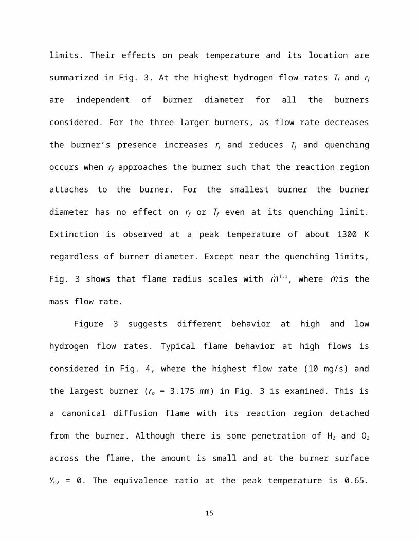
Table 1Experimental quenching limits
OxidizerH2
μg/sH2 . LHV
Wu
m/s
Re Fr Pe
Air 3.9 0.46 2.5 3.96 65 5.3O2 2.1 0.25 1.4 2.13 36 3.0
Table 2Selected H2-O2 reactions included in the simulations, from GRI Mech. 3.0 [18]
No. Reaction No. ReactionR1 2O+M → O2+M R43 H+OH+M→ H2O+MR2 O+H+M → OH+M R44 H+HO2 → O+H2OR3 O+H2 → H+OH R45 H+HO2 → O2+H2
R4 O+HO2 → OH+O2 R46 H+HO2 → 2OHR5 O+H2O2 → OH+HO2 R47 H+H2O2 → HO2+H2
R33 H+O2+M → HO2+M R48 H+H2O2 → OH+H2OR34 H+2O2 → HO2+O2 R84 OH+H2 → H+H2OR35 H+O2+H2O →
HO2+H2OR85R86
2OH+M → H2O2+M2OH → O+H2O
R36 H+O2+N2 → HO2+N2 R87 OH+HO2 → O2+H2OR38 H+O2 → O+OH R88 OH+H2O2 → HO2+H2OR39 2H+M → H2+M R89 OH+H2O2 → HO2+H2OR40 2H+H2 → 2H2 R115 2HO2 → O2+H2O2
R41 2H+H2O → H2+H2O R116 2HO2 → O2+H2O2
15
0.5 mm
WE
Fig. 1. Images of hydrogen flames at their quenching limits burning in air (left) and O2 (right). The tube inside and outside diameters are 0.15 and 0.30 mm. Camera exposures are ISO 200, f/1.4, 30 s. The word WE from a U.S. dime is shown at the same scale as the flames. Original in color.
16
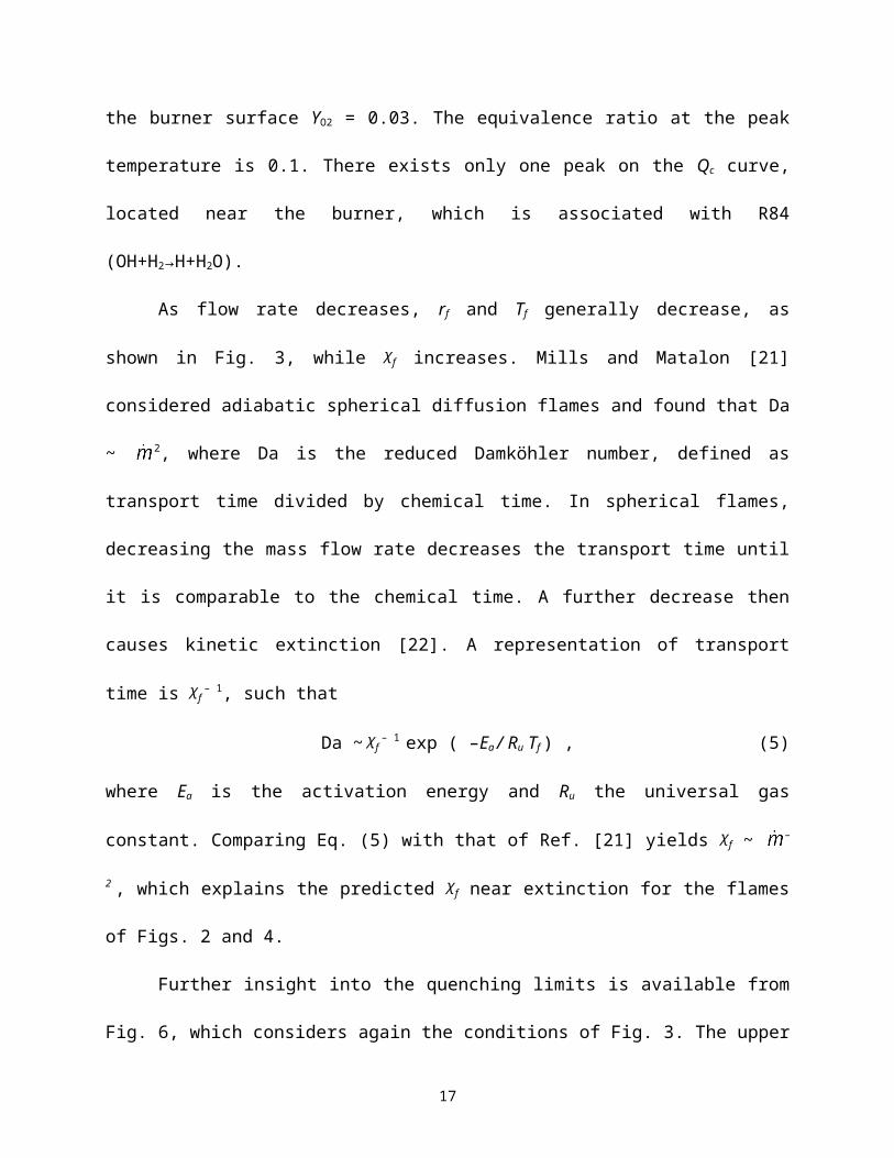
Fig. 2. Species mass fractions (top) and temperature and local heat release rates (bottom) for H2/air flames near their quenching limits. Burner radii, H2, and χf are 75 μm, 3.65 μg/s, and 0.98 s-1 (solid curves) and 1 μm, 3.49 μg/s, and 1.18 s-1 (dashed curves).
mH2 (mg/s)
T f(K)
r f(cm)
10-3 10-2 10-1 100 1011000
1500
2000
2500
10-2
10-1
100
101
102
3.175 mm
75 m1 m
300 m1 m
75 m
3.175 mm
300 m
T
r
.
Fig. 3. Predicted H2/air peak temperature and its radius versus hydrogen flow rate for four burner radii.
17
r (m)
T(K)
Q(W/cm3 )
0 100 200 300 4000
500
1000
1500
0
2000
4000
T
QCR35
R84
R38 R3
R46
R45
rb = 75 m
R36
R35R46
1500 4000Yi
10-6
10-5
10-4
10-3
10-2
10-1
100
H2
O2
O
H2O
OH
HO2
H
H2O2
rb=75 m
10-6
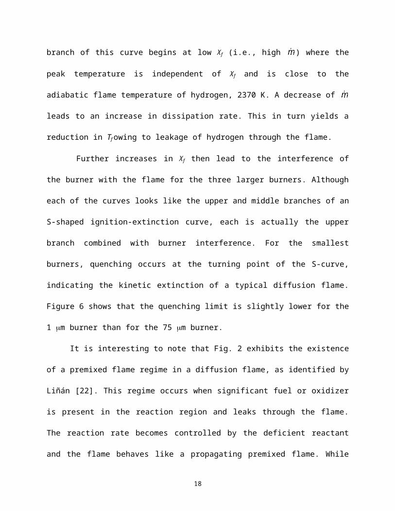
Fig. 4. Species mass fractions (top) and temperature and local heat release rates (bottom) for a large H2/air flame. Burner radii, H2 , and χf are 3.175 mm, 10 mg/s, and 5.2x10⁻⁶ s-1.
18
Yi
10-6
10-5
10-4
10-3
10-2
10-1
100
H2 O2
O
H2O
OH
H
10-6
r (cm)
T(K)
Q(W/cm3 )
0 10 20 30 40 500
500
1000
1500
2000
2500
-0.005
0
0.005
0.01
0.015
0.02T
QC
R85R84
R38
R87
R43
R86
R89R41R35
2500 0.02
Fig. 5. Species mass fractions (top) and temperature and local heat release rates (bottom) for an H2/air flame near its quenching limit. Burner radii, H2 , and χf are 3.175 mm, 0.1 mg/s, and 0.016 s-1.
f (s-1)
T f(K)
10-6 10-5 10-4 10-3 10-2 10-1 100 1011000
1500
2000
2500
3.175 mm
75 m
1 m
300 m
Fig. 6. Predicted H2/air peak temperature versus scalar dissipation rate for four burner radii.
19
Yi
10-6
10-5
10-4
10-3
10-2
10-1
100
H2
O2
O
H2O
OH
HO2
H
Burnersurface
10-6
r (m)
T(K)
Q(W/cm3 )
3000 3500 4000 45000
500
1000
1500
2000
2500
-50
0
50
100
150
200
T
QC
R35
R84
R38
R3R86
R43
Burnersurface
2500 200
Figure Captions
Fig. 1. Images of hydrogen flames at their quenching limits burning in air (left) and O2 (right). The tube inside and outside diameters are 0.15 and 0.30 mm. Camera exposures are ISO 200, f/1.4, 30 s. The word WE from a U.S. dime is shown at the same scale as the flames. Original in color.
Fig. 2. Species mass fractions (top) and temperature and local heat release rates (bottom) for H2/air flames near their quenching limits. Burner radii, H2, and χf are 75 μm, 3.65 μg/s, and 0.98 s-1 (solid curves) and 1 μm, 3.49 μg/s, and 1.18 s-1 (dashed curves).
Fig. 3. Predicted H2/air peak temperature and its radius versus hydrogen flow rate for four burner radii.
Fig. 4. Species mass fractions (top) and temperature and local heat release rates (bottom) for a large H2/air flame. Burner radii, H2 , and χf are 3.175 mm, 10 mg/s, and 5.2x10⁻⁶ s-1.
Fig. 5. Species mass fractions (top) and temperature and local heat release rates (bottom) for an H2/air flame near its quenching limit. Burner radii, H2 , and χf are 3.175 mm, 0.1 mg/s, and 0.016 s-1.
Fig. 6. Predicted H2/air peak temperature versus scalar dissipation rate for four burner radii.
20

![ANALYSIS OF JET FLAMES AND UNIGNITED JETS FROM … of Jet Flames... · Previous work performed by Sandia on unintended releases of hydrogen [1-3] focused on these high-momentum large-scale](https://img.pdfslide.net/doc/110x75/6060626fde80bb7e1c52d9e0/analysis-of-jet-flames-and-unignited-jets-from-of-jet-flames-previous-work.jpg)


![Acceleration of laminar hydrogen/oxygen flames in a tube and ...eprints.whiterose.ac.uk/127613/1/2018 Hydrogen Jour.pdf4 In contrast, many experimental [10-17] and numerical studies](https://img.pdfslide.net/doc/110x75/60f81b16fbfe56776659d381/acceleration-of-laminar-hydrogenoxygen-flames-in-a-tube-and-hydrogen-jourpdf.jpg)