Embed Size (px)
Citation preview

Last Update: January 2017
Front cover
Microsoft Storage Spaces Direct (S2D) Deployment Guide
Microsoft Software Defined Storage solution based on Windows Server 2016
Microsoft Software Defined Storage using Lenovo rack-based servers
Designed for Enterprise MSPs/CSPs, and HPC
High performing, high availability and scale out solution with growth potential
David Feisthammel
Daniel Lu
David Ye
Michael Miller

2 Microsoft Storage Spaces Direct (S2D) Deployment Guide
Abstract
As the high demand for storage continues to accelerate for enterprises in recent years, Lenovo® and Microsoft have teamed up to craft a software-defined storage solution leveraging the advanced feature set of Windows Server 2016 and the flexibility of the Lenovo System x3650 M5 rack server and RackSwitch™ G8272 switch.
This solution provides a solid foundation for customers looking to consolidate both storage and compute capabilities on a single hardware platform, or for those enterprises that wish to have distinct storage and compute environments. In both situations, this solution provides outstanding performance, high availability protection and effortless scale out growth potential to accommodate evolving business needs.
This deployment guide provides insight to the setup of this environment and guides the reader through a set of well-proven procedures leading to readiness of this solution for production use. This guide is based on Storage Spaces Direct as implemented in Windows Server 2016 RTM (Release to Manufacturing).
Contents
Storage Spaces Direct Solution Overview . . . . . . . . . . . . . . . . . . . . . . . . . . . . . . . . . . . . . . . 3Solution configuration. . . . . . . . . . . . . . . . . . . . . . . . . . . . . . . . . . . . . . . . . . . . . . . . . . . . . . . 6Overview of the installation tasks. . . . . . . . . . . . . . . . . . . . . . . . . . . . . . . . . . . . . . . . . . . . . 10Configure the physical network switches . . . . . . . . . . . . . . . . . . . . . . . . . . . . . . . . . . . . . . . 10Prepare the servers and storage . . . . . . . . . . . . . . . . . . . . . . . . . . . . . . . . . . . . . . . . . . . . . 13Install Windows Server 2016 . . . . . . . . . . . . . . . . . . . . . . . . . . . . . . . . . . . . . . . . . . . . . . . . 14Install Windows Server roles and features. . . . . . . . . . . . . . . . . . . . . . . . . . . . . . . . . . . . . . 15Configure the operating system . . . . . . . . . . . . . . . . . . . . . . . . . . . . . . . . . . . . . . . . . . . . . . 15Configure networking parameters . . . . . . . . . . . . . . . . . . . . . . . . . . . . . . . . . . . . . . . . . . . . 16Create the Failover Cluster . . . . . . . . . . . . . . . . . . . . . . . . . . . . . . . . . . . . . . . . . . . . . . . . . 20Enable and configure Storage Spaces Direct . . . . . . . . . . . . . . . . . . . . . . . . . . . . . . . . . . . 23Summary . . . . . . . . . . . . . . . . . . . . . . . . . . . . . . . . . . . . . . . . . . . . . . . . . . . . . . . . . . . . . . . 28Lenovo Professional Services . . . . . . . . . . . . . . . . . . . . . . . . . . . . . . . . . . . . . . . . . . . . . . . 29Appendix: Bill of Materials for hyperconverged solution . . . . . . . . . . . . . . . . . . . . . . . . . . . 29Change history . . . . . . . . . . . . . . . . . . . . . . . . . . . . . . . . . . . . . . . . . . . . . . . . . . . . . . . . . . . 30Authors. . . . . . . . . . . . . . . . . . . . . . . . . . . . . . . . . . . . . . . . . . . . . . . . . . . . . . . . . . . . . . . . . 31Notices . . . . . . . . . . . . . . . . . . . . . . . . . . . . . . . . . . . . . . . . . . . . . . . . . . . . . . . . . . . . . . . . . 33Trademarks . . . . . . . . . . . . . . . . . . . . . . . . . . . . . . . . . . . . . . . . . . . . . . . . . . . . . . . . . . . . . 34
Do you have the latest version? Check whether you have the latest version of this document by clicking the Check for Updates button on the front page of the PDF. Pressing this button will take you to a web page that will tell you if you are reading the latest version of the document and give you a link to the latest if needed. While you’re there, you can also sign up to get notified via email whenever we make an update.

Storage Spaces Direct Solution Overview
The initial offering of software-defined storage (SDS) in Windows Server 2012 was called “Storage Spaces.” The next iteration of this solution has been introduced in Windows Server 2016 under the name Storage Spaces Direct (S2D), and continues the concept of collecting a pool of affordable drives to form a large usable and shareable storage repository. In Windows Server 2016, the solution expands to encompass support for both SATA and SAS drives, including NVMe disk devices, that reside internally in the server.
Figure 1 shows an overview of the Storage Spaces Direct stack.
Figure 1 Storage Spaces Direct stack
When discussing high performance and shareable storage pools, many IT professionals think of expensive SAN infrastructure. Thanks to the evolution of disk and virtualization technology, as well as ongoing advancements in network throughput, the realization of having an economical, highly redundant and high performance storage subsystem is now present.
Key considerations of S2D are as follows:
� S2D capacity and storage growth
Leveraging the 14x 3.5” drive bays of the x3650 M5 and high-capacity drives such as the 4 TB drives in this solution, each server node is itself a JBOD (just a bunch of disks)
© Copyright Lenovo 2017. All rights reserved. 3

repository. As demand for storage and/or compute resources grows, additional x3650 M5 systems are added into the environment to provide the necessary storage expansion.
� S2D performance
Using a combination of solid-state drives (SSDs) and regular hard disk drives (HDDs) as the building blocks of the storage volume, an effective method for storage tiering is available. Faster-performing SSDs act as a cache repository to the capacity tier, which is placed on traditional HDDs in this solution. Data is striped across multiple drives, thus allowing for very fast retrieval from multiple read points.
At the physical network layer, 10GbE links are employed today. However, in the future, additional throughput needs can be satisfied by using higher bandwidth adapters. For now, the dual 10 GbE network paths that contain both Windows Server operating system and storage replication traffic are more than sufficient to support the workloads and show no indication of bandwidth saturation.
� S2D resilience
Traditional disk subsystem protection relies on RAID storage controllers. In S2D, high availability of the data is achieved using a non-RAID adapter and adopting redundancy measures provided by Windows Server 2016 itself. The storage can be configured as simple spaces, mirror spaces, or parity spaces.
– Simple spaces: Stripes data across a set of pool disks, and is not resilient to any disk failures. Suitable for high performance workloads where resiliency is either not necessary, or is provided by the application.
– Mirror spaces: Stripes and mirrors data across a set of pool disks, supporting a two-way or three-way mirror, which are respectively resilient to single disk, or double disk failures. Suitable for the majority of workloads, in both clustered and non-clustered deployments.
– Parity spaces: Stripes data across a set of pool disks, with a single disk write block used to store parity information, and is resilient to a single disk failure. Suitable for large block append-style workloads, such as archiving, in non-clustered deployments.
� S2D use cases
The importance of having a SAN in the enterprise space as the high-performance and high-resilience storage platform is changing. The S2D solution is a direct replacement for this role. Whether the primary function of the environment is to provide Windows applications or a Hyper-V virtual machine farm, S2D can be configured as the principal storage provider to these environments. Another use for S2D is as a repository for backup or archival of VHD(X) files. Wherever a shared volume is applicable for use, S2D can be the new solution to support this function.
S2D supports two general deployment scenarios, which have been called disaggregated and hyperconverged. Microsoft sometimes uses the term “converged” to describe the disaggregated deployment scenario. Both scenarios provide storage for Hyper-V, specifically focusing on Hyper-V Infrastructure as a Service (IaaS) for service providers and enterprises.
In the disaggregated approach, the environment is separated into compute and storage components. An independent pool of servers running Hyper-V acts to provide the CPU and memory resources (the “compute” component) for the running of VMs that reside on the storage environment. The “storage” component is built using S2D and Scale-Out File Server (SOFS) to provide an independently scalable storage repository for the running of VMs and applications. This method, as illustrated in Figure 2 on page 5, allows for the independent scaling and expanding of the compute farm (Hyper-V) and the storage farm (S2D).
4 Microsoft Storage Spaces Direct (S2D) Deployment Guide

Figure 2 Disaggregated configuration - nodes do not run Hyper-V
For the hyperconverged approach, there is no separation between the resource pools for compute and storage. Instead, each server node provides hardware resources to support the running of VMs under Hyper-V, as well as the allocation of its internal storage to contribute to the S2D storage repository.
Figure 3 on page 6 demonstrates this all-in-one configuration for a four-node hyperconverged solution. When it comes to growth, each additional node added to the environment will mean both compute and storage resources are increased together. Perhaps workload metrics dictate that a specific resource increase is sufficient to cure a bottleneck (e.g., CPU resources). Nevertheless, any scaling will mean the addition of both compute and storage resources. This is a fundamental limitation for all hyperconverged solutions.
5

Figure 3 Hyperconverged configuration - nodes provide shared storage and Hyper-V hosting
Solution configuration
The primary difference between configuring the two deployment scenarios is that no vSwitch creation is necessary in the disaggregated solution, since the S2D cluster is used only for the storage component and does not host VMs. This document specifically addresses the deployment of a Storage Spaces Direct hyperconverged solution. If a disaggregated solution is preferred, it is a simple matter of skipping a few configuration steps, which will be highlighted along the way.
The following components and information are relevant to the test environment used to develop this guide. This solution consists of two key components, a high-throughput network infrastructure and a storage-dense high-performance server farm.
In this solution, the networking component consists of a pair of Lenovo RackSwitch G8272 switches, which are connected to each node via 10GbE Direct Attach Copper (DAC) cables. In addition to the Mellanox ConnectX-4 NICs described in this document, Lenovo also supports Chelsio T520-LL-CR dual-port 10GbE network cards that use the iWARP protocol. This Chelsio NIC can be ordered via the CORE special-bid process as Lenovo part number 46W0609. Contact your local Lenovo client representative for more information. Although the body of this document details the steps required to configure the Mellanox cards, it is a simple matter to substitute Chelsio NICs in the solution.
6 Microsoft Storage Spaces Direct (S2D) Deployment Guide

The server/storage farm is built using four Lenovo System x3650 M5 servers equipped with multiple storage devices. Supoprted storage devices include HDD, SSD, and NVMe media types, although Microsoft currently advises against configuring a solution using all three media types. A four-node cluster is the minimum configuration required to harness the failover capability of losing any two nodes.
Figure 4 shows high-level details of the configuration. The four server/storage nodes and two switches take up a combined total of 10 rack units of space.
Figure 4 Solution rack configuration using System x3650 M5 systems
Figure 5 on page 8 shows the layout of the drives. There are 14x 3.5” drives in the server, 12 at the front of the server and two at the rear of the server. Four are 800 GB SSD devices, while the remaining ten drives are 4 TB SATA HDDs. These 14 drives form the tiered storage pool of S2D and are connected to the N2215 SAS HBA. Two 2.5” drive bays at the rear of the server contain a pair of 600 GB SAS HDDs that are mirrored (RAID-1) for the boot drive and connected to the ServeRAID™ M1215 SAS RAID adapter.
One of the requirements for this solution is that a non-RAID storage controller is used for the S2D data volume. Note that using a RAID storage controller set to pass-through mode is not supported at the time of this writing. The ServeRAID adapter is required for high availability of the operating system and is not used by S2D for its storage repository.
The use of RAID controllers: Microsoft does not support any RAID controller attached to the storage devices used by S2D, regardless of a controller’s ability to support “pass-through” or JBOD mode. As a result, the N2215 SAS HBA is used in this solution. The ServeRAID M1215 controller is used only for the pair of mirrored (RAID-1) boot drives and has nothing to do with S2D.
Networking: Two Lenovo RackSwitch G8272 switches, each containing:
� 48 ports at 10Gbps SFP+� 4 ports at 40Gbps QSFP+
Compute: Four Lenovo System x3650 M5 servers, each containing:
� Two Intel Xeon E5-2680 v4 processors� 256 GB memory� One quad-port 1GbE adapter (not used in solution)� One dual-port 10GbE Mellanox ConnectX-4 PCIe adapter
with RoCE support
Storage in each x3650 M5 server:
� Twelve 3.5” HDD at front� Two 3.5” HDD + Two 2.5” HDD at rear� ServeRAID M1215 SAS RAID adapter� N2215 SAS HBA (LSI SAS3008 12 Gbps)
7

Figure 5 x3650 M5 storage subsystem
Network wiring of this solution is straight-forward, with each server being connected to each switch to enhance availability. Each system contains a dual-port 10 GbE Mellanox ConnectX-4 adapter to handle operating system traffic and storage communications.
Figure 6 Server to switch network connectivity
To allow for redundant network links in the event of a network port or external switch failure, the recommendation calls for the connection from Port 1 on the Mellanox adapter to be joined to a port on the first G8272 switch (“S2DSwitch1”), plus a connection from Port 2 on the same Mellanox adapter to be linked to an available port on the second G8272 switch (“S2DSwitch2”). This cabling construct is illustrated in Figure 6. Defining an Inter-Switch Link (ISL) ensures failover capabilities on the switches.
The last construction on the network subsystem is to leverage the virtual network capabilities of Hyper-V on each host to create a SET-enabled team from both 10 GbE ports on the Mellanox adapter. From this a virtual switch (vSwitch) is defined and logical network adapters
8 Microsoft Storage Spaces Direct (S2D) Deployment Guide

(vNICs) are created to facilitate the operating system and storage traffic. Note that for the disaggregated solution, the SET team, vSwitch, and vNICs are not created.
Also, for the disaggregated solution, the servers are configured with 128 GB of memory, rather than 256 GB, and the CPU has 10 cores instead of 14 cores. The higher-end specifications of the hyperconverged solution are to account for the dual functions of compute and storage that each server node will take on, whereas in the disaggregated solution, there is a separation of duties, with one server farm dedicated to Hyper-V hosting and a second devoted to S2D.
9

Overview of the installation tasks
This document specifically addresses the deployment of a Storage Spaces Direct hyperconverged solution. Although nearly all configuration steps presented apply to the disaggregated solution as well, there are a few differences between these two solutions. We have included notes regarding steps that do not apply to the disaggregated solution. These notes are also included as comments in PowerShell scripts.
A number of tasks need to be performed in order to configure this solution. If completed in a stepwise fashion, this is not a difficult endeavor. The high-level steps described in the remaining sections of the paper are as follows:
1. “Configure the physical network switches” on page 10
2. “Prepare the servers and storage” on page 13
3. “Install Windows Server 2016” on page 14
4. “Install Windows Server roles and features” on page 15
5. “Configure the operating system” on page 15
6. “Configure networking parameters” on page 16
7. “Create the Failover Cluster” on page 20
8. “Enable and configure Storage Spaces Direct” on page 23
Configure the physical network switches
Like Windows Server 2012 R2, Windows Server 2016 includes a feature called SMB Direct, which supports the use of network adapters that have the Remote Direct Memory Access (RDMA) capability. Network adapters that support RDMA can function at full speed with very low latency, while using very little CPU. For workloads such as Hyper-V or Microsoft SQL Server, this enables a remote file server to resemble local storage.
SMB Direct provides the following benefits:
� Increased throughput: Leverages the full throughput of high speed networks where the network adapters coordinate the transfer of large amounts of data at line speed.
� Low latency: Provides extremely fast responses to network requests and, as a result, makes remote file storage feel as if it is directly attached block storage.
� Low CPU utilization: Uses fewer CPU cycles when transferring data over the network, which leaves more power available to server applications, including Hyper-V.
Leveraging the benefits of SMB Direct comes down to a few simple principles. First, using hardware that supports SMB Direct and RDMA is critical. Use the Bill of Materials found in “Appendix: Bill of Materials for hyperconverged solution” on page 29 as a guide. This solution utilizes a pair of Lenovo RackSwitch G8272 10/40 Gigabit Ethernet switches and a dual-port 10GbE Mellanox ConnectX-4 PCIe adapter for each node.
Redundant physical network connections are a best practice for resiliency as well as bandwidth aggregation. This is a simple matter of connecting each node to each switch. In our solution, Port 1 of each Mellanox adapter is connected to the Switch 1 and Port 2 of each Mellanox adapter is connected to Switch 2, as shown in Figure 7 on page 11.
10 Microsoft Storage Spaces Direct (S2D) Deployment Guide

Figure 7 Switch to node cabling
As a final bit of network cabling, we configure an Inter-Switch Link (ISL) between our pair of switches to support the redundant node-to-switch cabling described above. To do this, we need redundant high-throughput connectivity between the switches, so we connect Ports 53 and 54 on each switch to each other using a pair of 40Gbps QSFP+ cables. Note that these connections are not shown in Figure 7.
In order to leverage the SMB Direct benefits listed above, a set of cascading requirements must be met. Using RDMA over Converged Ethernet (RoCE) requires a lossless fabric, which is typically not provided by standard TCP/IP Ethernet network infrastructure, since the TCP protocol is designed as a “best-effort” transport protocol. Datacenter Bridging (DCB) is a set of enhancements to IP Ethernet, which is designed to eliminate loss due to queue overflow, as well as to allocate bandwidth between various traffic types.
To sort out priorities and provide lossless performance for certain traffic types, DCB relies on Priority Flow Control (PFC). Rather than using the typical Global Pause method of standard Ethernet, PFC specifies individual pause parameters for eight separate priority classes. Since the priority class data is contained within the VLAN tag of any given traffic, VLAN tagging is also a requirement for RoCE and, therefore SMB Direct.
Once the network cabling is done, it's time to begin configuring the switches. These configuration commands need to be executed on both switches. We start by enabling Converged Enhanced Ethernet (CEE), which automatically enables Priority-Based Flow Control (PFC) for all Priority 3 traffic on all ports. Enabling CEE also automatically configures Enhanced Transmission Selection (ETS) so that at least 50% of the total bandwidth is always
Switch 2
Switch 1
Node 1
Node 2
Node 3
Node 4
11

available for our storage (PGID 1) traffic. These automatic default configurations are suitable for our solution. The commands are listed in Example 1.
Example 1 Enable CEE on the switch
enableconfigure terminalcee enable
After enabling CEE, we configure the vLANs. Although we could use multiple vLANs for different types of network traffic (storage, client, management, cluster heartbeat, Live Migration, etc.), the simplest choice is to use a single vLAN (12) to carry all our SMB Direct solution traffic. Employing 10GbE links makes this a viable scenario. Enabling vLAN tagging is important in this solution, since RDMA requires it.
Example 2 Establish vLAN for all solution traffic
vlan 12name SMBexitinterface port 1-4,53-54switchport mode trunkswitchport trunk allowed vlan add 12exit
For redundancy, we configure an ISL between a pair of 40GbE ports on each switch. We use the last two ports, 53 and 54, for this purpose. Physically, each port is connected to the same port on the other switch using a 40Gbps QSFP+ cable. Configuring the ISL is a simple matter of joining the two ports into a port trunk group. See Example 3.
Example 3 Configure an ISL between switches for resiliency
interface port 53-54pvid 4094switchport mode trunklacp mode activelacp key 100exit
Once we've got the configuration complete on the switch, we need to copy the running configuration to the startup configuration. Otherwise, our configuration changes would be lost once the switch is reset or reboots. This is achieved using the write command, Example 4.
Example 4 Use the write command to copy the running configuration to startup
write
Repeat the entire set of commands above (Example 1 on page 12 through Example 4) on the other switch, defining the same vLAN and port trunk on that switch. Since we are using the same ports on both switches for identical purposes, the commands that are run on each switch are identical. Remember to commit the configuration changes on both switches using the write command.
Note: If the solution uses another switch model or switch vendor’s equipment, other than the RackSwitch G8272, it is essential to perform the equivalent command sets for the switches. The commands themselves may differ from what is stated above but it is imperative that the same functions are executed on the switches to ensure proper operation of this solution.
12 Microsoft Storage Spaces Direct (S2D) Deployment Guide

Prepare the servers and storage
In this section, we describe updating firmware and drivers, and configuring the RAID subsystem for the boot drive in the server nodes.
Firmware and drivers
Best practices dictate that with a new server deployment, the first task is to review the system firmware and drivers relevant to the incoming operating system. If the system has the latest firmware and drivers installed it will expedite tech support calls, and may reduce the need for such calls. Lenovo has a useful tool for this important task called UpdateXpress.
https://support.lenovo.com/us/en/documents/lnvo-xpress
UpdateXpress can be utilized in two ways:
� The first option allows the system administrator to download and install the tool on the target server, perform a verification to identify any firmware and drivers that need attention, download the update packages from the Lenovo web site, and then proceed with the updates.
� The second method lets the server owner download the new packages to a local network share or repository and then install the updates during a maintenance window.
This flexibility in the tool grants full control to the server owner and ensures that these important updates are performed at a convenient time.
Windows Server 2016 contains all the drivers necessary for this solution with the exception of the Mellanox ConnectX-4 driver, which was updated by Mellanox after the final Release to Manufacturing (RTM) build of the OS was released. To obtain the latest CX-4 driver, visit:
http://www.mellanox.com/page/products_dyn?product_family=32&mtag=windows_driver
In addition, it is recommended to install the Lenovo IMM2 PBI mailbox driver. Although this is actually a null driver and is not required for the solution, installing this driver removes the “bang” from the Unknown device in the Windows Device Manager. You can find the driver here:
https://www-945.ibm.com/support/fixcentral/systemx/selectFixes?parent=Lenovo%2BSystem%2Bx3650%2BM5&product=ibm/systemx/8871&&platform=Windows+2012+R2&function=all#IMMPBI
Physical storage subsystem
Follow these steps to configure a RAID-1 array for the operating system:
1. Power on the server to review the drive subsystem in preparation for the installation of the operating system.
2. During the system boot process, press the F1 key to initiate the UEFI menu screen, Figure 8. Traverse to System Settings, Storage, and then access the ServeRAID M1215 controller.
13

Figure 8 UEFI main menu
3. Create a RAID-1 pool from the two 2.5” HDDs installed at the rear of the system.
Leave the remaining 12 drives (four 800 GB SSDs and ten 4 TB HDDs) that are connected to the N2215 SAS HBA as unconfigured. They will be managed directly by the operating system when the time comes to creating the storage pool.
Install Windows Server 2016
You can install Windows from a variety of sources:
� Remote ISO media mount via the IMM� Bootable USB media with the installation content� Installation DVD
System x® servers, including the x3650 M5, feature an Integrated Management Module (IMM) to provide remote out-of-band management, including remote control and remote media.
Select the source that is appropriate for your situation. The following steps describe the installation:
1. With the method of Windows deployment selected, power the server on to begin the installation process.
2. Select the appropriate language pack, correct input device, and the geography, then select the desired OS edition (GUI or Core components only).
3. Select the RAID-1 array connected to the ServeRAID M1215 controller as the target to install Windows (you might need to scroll through a list of available drives).
4. Follow the prompts to complete the installation of the OS.
Windows Server 2016 contains all the drivers necessary for this solution with the exception of the Mellanox ConnectX-4 driver, which was updated by Mellanox after the final Release to Manufacturing (RTM) build of the OS was released. To obtain the latest CX-4 driver, visit:
http://www.mellanox.com/page/products_dyn?product_family=32&mtag=windows_driver
14 Microsoft Storage Spaces Direct (S2D) Deployment Guide

In addition, it is recommended to install the Lenovo IMM2 PBI mailbox driver. Although this is actually a null driver and is not required for the solution, installing this driver removes the “bang” from the Unknown device in the Windows Device Manager. You can find the driver here:
https://www-945.ibm.com/support/fixcentral/systemx/selectFixes?parent=Lenovo%2BSystem%2Bx3650%2BM5&product=ibm/systemx/8871&&platform=Windows+2012+R2&function=all#IMMPBI
Install Windows Server roles and features
Several Windows Server roles and features are used by this solution. It makes sense to install them all at the same time, then perform specific configuration tasks later. To make this installation quick and easy, use the following PowerShell script, Example 5 on page 15.
Example 5 PowerShell script to install necessary server roles and features
Install-WindowsFeature -Name File-ServicesInstall-WindowsFeature -Name Failover-Clustering -IncludeManagementToolsInstall-WindowsFeature -Name Hyper-V -IncludeManagementTools -Restart
Note that it is a good idea to install the Hyper-V role on all nodes even if you plan to implement the disaggregated solution. Although you may not regularly use the storage cluster to host VMs, if the Hyper-V role is installed, you will have the option to deploy an occasional VM if the need arises.
Once the roles and features have been installed and the nodes are back online, operating system configuration can begin.
Configure the operating system
Next, we configure the operating system, including Windows Update, AD Domain join, and internal drive verification.
To ensure that the latest fixes and patches are applied to the operating system, perform updating of the Windows Server components via Windows Update. It is a good idea to reboot each node after the final update is applied to ensure that all updates have been fully installed, regardless what Windows Update indicates.
Upon completing the Windows Update process, join each server node to the Windows Active Directory Domain. Use the following PowerShell command to accomplish this task.
Example 6 PowerShell command to add system to an Active Directory Domain
Add-Computer -DomainName <DomainName> -Reboot
From this point onward, when working with cluster services be sure to log onto the systems with a Domain account and not the local Administrator account. Ensure that a Domain account is part of the local Administrators Security Group, as shown in Figure 9.
15

Figure 9 Group membership of the Administrator account
Verify that the internal drives are online, by going to Server Manager > Tools > Computer Management > Disk Management. If any are offline, select the drive, right-click it, and click Online. Alternatively, PowerShell can be used to bring all 14 drives in each host online with a single command.
Example 7 PowerShell command to bring all 14 drives online
Get-Disk | ? FriendlyName -Like *ATA* | Set-Disk -IsOffline $False
Since all systems have been joined to the domain, we can execute the PowerShell command remotely on the other hosts while logged in as a Domain Administrator. To do this, use the command shown in Example 8.
Example 8 PowerShell command to bring drives online in remote systems
Invoke-Command -ComputerName S2D02, S2D03, S2D04 -ScriptBlock {Get-Disk | ? FriendlyName -Like *ATA* | Set-Disk -IsOffline $False}
Configure networking parameters
Now that the required Windows Server roles and features have been installed, we turn our attention to some network configuration details.
For the Mellanox NICs used in this solution, we need to enable Data Center Bridging (DCB), which is required for RDMA. Then we create a policy to establish network Quality of Service (QoS) to ensure that the Software Defined Storage system has enough bandwidth to communicate between the nodes, ensuring resiliency and performance. We also need to disable regular Flow Control (Global Pause) on the Mellanox adapters, since Priority Flow Control (PFC) and Global Pause cannot operate together on the same interface.
To make all these changes quickly and consistently, we again use a PowerShell script, as shown in Example 9 on page 17.
16 Microsoft Storage Spaces Direct (S2D) Deployment Guide

Example 9 PowerShell script to configure required network parameters on servers
# Enable Data Center Bridging (required for RDMA)Install-WindowsFeature -Name Data-Center-Bridging# Configure a QoS policy for SMB-DirectNew-NetQosPolicy "SMB" -NetDirectPortMatchCondition 445 -PriorityValue8021Action 3# Turn on Flow Control for SMBEnable-NetQosFlowControl -Priority 3# Make sure flow control is off for other trafficDisable-NetQosFlowControl -Priority 0,1,2,4,5,6,7# Apply a Quality of Service (QoS) policy to the target adaptersEnable-NetAdapterQos -Name "Mellanox 1","Mellanox 2"# Give SMB Direct a minimum bandwidth of 50%New-NetQosTrafficClass "SMB" -Priority 3 -BandwidthPercentage 50 -Algorithm ETS# Disable Flow Control on physical adaptersSet-NetAdapterAdvancedProperty -Name "Mellanox 1" -RegistryKeyword "*FlowControl" -RegistryValue 0Set-NetAdapterAdvancedProperty -Name "Mellanox 2" -RegistryKeyword "*FlowControl" -RegistryValue 0
For an S2D hyperconverged solution, we deploy a SET-enabled Hyper-V switch and add RDMA-enabled host virtual NICs to it for use by Hyper-V. Since many switches won't pass traffic class information on untagged vLAN traffic, we need to make sure that the vNICs using RDMA are on vLANs.
To keep this hyperconverged solution as simple as possible and since we are using dual-port 10GbE NICs, we will pass all traffic on vLAN 12. If you need to segment your network traffic more, for example to isolate VM Live Migration traffic, you can use additional vLANs.
Example 10 shows the PowerShell script that can be used to perform the SET configuration, enable RDMA, and assign vLANs to the vNICs. These steps are necessary only for configuring a hyperconverged solution. For a disaggregated solution these steps can be skipped since Hyper-V is not enabled on the S2D storage nodes.
Example 10 PowerShell script to create a SET-enabled vSwitch in hyperconverged solution
# Create a SET-enabled vSwitch supporting multiple uplinks provided by the Mellanox adapterNew-VMSwitch -Name S2DSwitch -NetAdapterName "Mellanox 1", "Mellanox 2" -EnableEmbeddedTeaming $true -AllowManagementOS $false# Add host vNICs to the vSwitch just createdAdd-VMNetworkAdapter -SwitchName S2DSwitch -Name SMB1 -ManagementOSAdd-VMNetworkAdapter -SwitchName S2DSwitch -Name SMB2 -ManagementOS# Enable RDMA on the vNICs just createdEnable-NetAdapterRDMA -Name "vEthernet (SMB1)","vEthernet (SMB2)"# Assign the vNICs to a vLANSet-VMNetworkAdapterVlan -VMNetworkAdapterName SMB1 -VlanId 12 -Access –ManagementOSSet-VMNetworkAdapterVlan -VMNetworkAdapterName SMB2 -VlanId 12 -Access –ManagementOS
Now that all network interfaces have been created (including the vNICs required by a hyperconverged deployment if necessary), IP address configuration can be completed, as follows:
1. Configure a static IP address for the operating system or public facing interface on the SMB1 vNIC (for example, 10.10.10.x). Configure default gateway and DNS server settings as appropriate for your environment.
Note: If using Chelsio NICs, the configuration steps shown in Example 9 are not necessary.
17

2. Configure a static IP address on the SMB2 vNIC, using a different subnet if desired (for example, 10.10.11.x). Again, configure default gateway and DNS server settings as appropriate for your environment.
3. Perform a ping command from each interface to the corresponding server nodes in this environment to confirm that all connections are functioning properly. Both interfaces on each node should be able to communicate with both interfaces on all other nodes.
Of course, PowerShell can be used to make IP address assignments if desired. Example 11 shows the commands used to specify a static IP address and DNS server assignment for Node 1 in our environemnt. Make sure to change the IP addresses and subnet masks (prefix length) to appropriate values for your environment.
Example 11 PowerShell commands used to configure the SMB vNIC interfaces on Node 1
Set-NetIPInterface -InterfaceAlias "vEthernet (SMB1)" -Dhcp DisabledNew-NetIPAddress -InterfaceAlias "vEthernet (SMB1)" -IPAddress 10.10.10.11 -PrefixLength 24Set-DnsClientServerAddress -InterfaceAlias "vEthernet (SMB1)" -ServerAddresses 10.10.10.1Set-NetIPInterface -InterfaceAlias "vEthernet (SMB2)" -Dhcp DisabledNew-NetIPAddress -InterfaceAlias "vEthernet (SMB2)" -IPAddress 10.10.11.11 -PrefixLength 24Set-DnsClientServerAddress -InterfaceAlias "vEthernet (SMB2)" -ServerAddresses 10.10.10.1
It's a good idea to disable any network interfaces that won't be used for the solution before creating the Failover Cluster. This includes IBM USB Remote NDIS Network device. The only interfaces that will be used in this solution are the SMB1 and SMB2 vNICs.
Figure 10 shows the network connections. The top two connections (in blue box) represent the two physical ports on the Mellanox adapter and must remain enabled. The next connection (in red box) represents the IBM USB Remote NDIS Network device, which can be disabled. Finally, the bottom two connections (in the green box) are the SMB Direct vNICs that will be used for all solution network traffic. There may be additional network interfaces listed, such as those for multiple Broadcom NetXtreme Gigabit Ethernet NICs. These should be disabled as well.
Figure 10 Windows network connections
Since RDMA is so critical to the performance of the final solution, it’s a good idea to make sure each piece of the configuration is correct as we move through the steps. We can’t look for RDMA traffic yet, but we can verify that the vNICs (in a hyperconverged solution) have RDMA enabled. Example 12 on page 18 shows the PowerShell command we use for this purpose and Figure 11 on page 19 shows the output of that command in our environment.
Example 12 PowerShell command to verify that RDMA is enabled on the vNICs just created
Get-NetAdapterRdma | ? Name -Like *SMB* | ft Name, Enabled
18 Microsoft Storage Spaces Direct (S2D) Deployment Guide

Figure 11 PowerShell command verifies that RDMA is enabled on a pair of vNICs
Using Virtual Machine Queue
For the 10GbE Mellanox adapters in our solution, the operating system automatically enables dynamic VMQ and RSS, which improve network performance and throughput to the VMs. VMQ is a scaling network technology for Hyper-V switch that improves network throughput by distributing processing of network traffic for multiple VMs among multiple processors. When VMQ is enabled, a dedicated queue is established on the physical NIC for each vNIC that has requested a queue. As packets arrive for a vNIC, the physical NIC places them in that vNIC's queue. These queues are managed by the system's processors.
Although not strictly necessary, it is a best practice to assign base and maximum processors for VMQ queues on each server in order to ensure maximum efficiency of queue management. Although the concept is straight forward, there are a few things to keep in mind when determining proper processor assignment. First, only physical processors are used to manage VMQ queues. Therefore, if Hyper-Threading (HT) Technology is enabled, only the even-numbered processors are considered viable. Next, since processor 0 is assigned to many internal tasks, it is best not to assign queues to this particular processor.
Before configuring VMQ queue management, execute a couple of PowerShell commands to gather in-formation. We need to know if HT is enabled and how many processors are available. You can issue a WMI query for this, comparing the “NumberOfCores” field to the “NumberOfLogicalProcessors” field. As an alternative, issue the Get-NetAdapterRSS command to see a list of viable processors (remember not to use Processor 0:0/0) as shown in Example 13.
Example 13 PowerShell commands used to determine processors available for VMQ queues
# Check for Hyper-Threading (if there are twice as many logical procs as number of cores, HT is enabled)Get-WmiObject -Class win32_processor | ft -Property NumberOfCores, NumberOfLogicalProcessors -AutoSize# Check procs available for queues (check the RssProcessorArray field)Get-NetAdapterRSS
Once you have this information, it's a simple math problem. We have a pair of 14-core CPUs in each host, providing 28 processors total, or 56 logical processors, including Hyper-Threading. Excluding processor 0 and eliminating all odd-numbered processors leaves us with 27 processors to assign. Given the dual-port Mellanox adapter, this means we can assign 13 processors to one port and 14 processors to the other. This results in the following processor assignment:
Mellanox 1: procs 2, 4, 6, 8, 10, 12, 14, 16, 18, 20, 22, 24, 26, 28Mellanox 2: procs 30, 32, 34, 46, 38, 40, 42, 44, 46, 48, 50, 52, 54
Use the following PowerShell script to define the base (starting) processor as well as how many processors to use for managing VMQ queues on each physical NIC consumed by the vSwitch (in our solution, the two Mellanox ports.)
Example 14 PowerShell script to assign processors for VMQ queue management
# Configure the base and maximum processors to use for VMQ queuesSet-NetAdapterVmq -Name "Mellanox 1" -BaseProcessorNumber 2 -MaxProcessors 14
19

Set-NetAdapterVmq -Name "Mellanox 2" -BaseProcessorNumber 30 -MaxProcessors 13# Check VMQ queuesGet-NetAdapterVmqQueue
Now that we’ve got the networking internals configured for one system, we use PowerShell remote execution to replicate this configuration to the other three hosts. Example 15 shows the PowerShell commands, this time without comments. These commands are for configuring a hyperconverged solution using Mellanox NICs. If Chelsio NICs are being used, eliminate the first 9 steps. If configuring a disaggregated solution, eliminate the last 9 steps.
Example 15 PowerShell remote execution script to configure networking on remaining hosts
Invoke-Command -ComputerName S2D02, S2D03, S2D04 -ScriptBlock {Install-WindowsFeature -Name Data-Center-BridgingNew-NetQosPolicy "SMB" -NetDirectPortMatchCondition 445 -PriorityValue8021Action 3Enable-NetQosFlowControl -Priority 3Disable-NetQosFlowControl -Priority 0,1,2,4,5,6,7Enable-NetAdapterQos -Name "Mellanox 1","Mellanox 2"New-NetQosTrafficClass "SMB" -Priority 3 -BandwidthPercentage 50 -Algorithm ETSSet-NetAdapterAdvancedProperty -Name "Mellanox 1" -RegistryKeyword "*FlowControl" -RegistryValue 0Set-NetAdapterAdvancedProperty -Name "Mellanox 2" -RegistryKeyword "*FlowControl" -RegistryValue 0New-VMSwitch –Name S2DSwitch –NetAdapterName "Mellanox 1", "Mellanox 2" -EnableEmbeddedTeaming $true -AllowManagementOS $falseAdd-VMNetworkAdapter –SwitchName S2DSwitch –Name SMB1 –ManagementOSAdd-VMNetworkAdapter –SwitchName S2DSwitch –Name SMB2 –ManagementOSEnable-NetAdapterRDMA -Name “vEthernet (SMB1)”,“vEthernet (SMB2)”Set-VMNetworkAdapterVlan -VMNetworkAdapterName SMB1 -VlanId 12 -Access –ManagementOSSet-VMNetworkAdapterVlan -VMNetworkAdapterName SMB2 -VlanId 12 -Access –ManagementOSSet-NetAdapterVmq -Name "Mellanox 1" -BaseProcessorNumber 2 -MaxProcessors 14Set-NetAdapterVmq -Name "Mellanox 2" -BaseProcessorNumber 30 -MaxProcessors 13}
The final piece of preparing the infrastructure for S2D is to create the Failover Cluster.
Create the Failover Cluster
Before creating the Failover Cluster we need to validate the components that are necessary to form the cluster. As an alternative to using the GUI, the following PowerShell commands can be used to test and create the Failover Cluster, Example 16.
Example 16 PowerShell commands to test and create a failover cluster
Test-Cluster -Node S2D01,S2D02,S2D03,S2D04 -Include "Storage Spaces Direct",Inventory,Network,"System Configuration"New-Cluster -Name S2DCluster -Node S2D01,S2D02,S2D03,S2D04 -NoStorage
Once the cluster is built, you can also use PowerShell to query the health status of the cluster storage.
Example 17 PowerShell command to check the status of cluster storage
Get-StorageSubSystem S2DCluster
The default behavior of Failover Cluster creation is to set aside the non-public facing subnet (configured on the SMB2 vNIC) as a cluster heartbeat network. When 1 GbE was the standard, this made perfect sense. However, since we are using 10 GbE in this solution, we
20 Microsoft Storage Spaces Direct (S2D) Deployment Guide
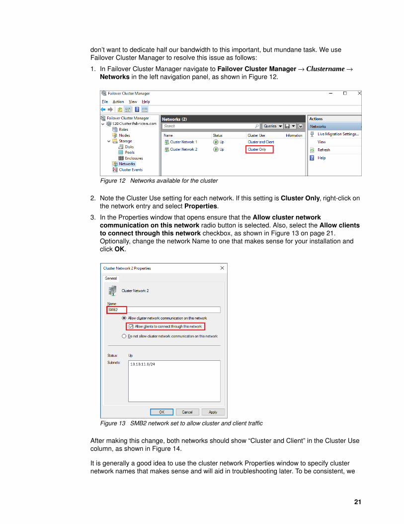
don’t want to dedicate half our bandwidth to this important, but mundane task. We use Failover Cluster Manager to resolve this issue as follows:
1. In Failover Cluster Manager navigate to Failover Cluster Manager → Clustername → Networks in the left navigation panel, as shown in Figure 12.
Figure 12 Networks available for the cluster
2. Note the Cluster Use setting for each network. If this setting is Cluster Only, right-click on the network entry and select Properties.
3. In the Properties window that opens ensure that the Allow cluster network communication on this network radio button is selected. Also, select the Allow clients to connect through this network checkbox, as shown in Figure 13 on page 21. Optionally, change the network Name to one that makes sense for your installation and click OK.
Figure 13 SMB2 network set to allow cluster and client traffic
After making this change, both networks should show “Cluster and Client” in the Cluster Use column, as shown in Figure 14.
It is generally a good idea to use the cluster network Properties window to specify cluster network names that makes sense and will aid in troubleshooting later. To be consistent, we
21

name our cluster networks after the vNICs that carry the traffic for each, as shown in Figure 14.
Figure 14 Cluster networks shown with names to match the vNICs that carry their traffic
It is also possible to accomplish the cluster network role and name changes using PowerShell. Example 18 provides a script to do this.
Example 18 PowerShell script to change names and roles of cluster networks
# Update the cluster networks that were created by default# First, look at what's thereGet-ClusterNetwork | ft Name, Role, Address# Change the cluster network names so they're consistent with the individual nodes(Get-ClusterNetwork -Name "Cluster Network 1").Name = "SMB1"(Get-ClusterNetwork -Name "Cluster Network 2").Name = "SMB2"# Enable Client traffic on the second cluster network(Get-ClusterNetwork -Name "SMB2").Role = 3# Check to make sure the cluster network names and roles are set properlyGet-ClusterNetwork | ft Name, Role, Address
Figure 15 shows output of the PowerShell commands to display the initial cluster network parameters, modify the cluster network names, enable client traffic on the second cluster network, and check to make sure cluster network names and roles are set properly.
Figure 15 PowerShell output showing cluster network renaming and results
22 Microsoft Storage Spaces Direct (S2D) Deployment Guide

You can also verify the cluster network changes by viewing them in Failover Cluster Manager by navigating to Failover Cluster Manager → Clustername → Networks in the left navigation panel.
Cluster file share witness
It is recommended to create a cluster file share witness. The cluster file share witness quorum configuration enables the 4-node cluster to withstand up to two node failures.
For information on how to create a cluster file share witness, read the Microsoft article, Configuring a File Share Witness on a Scale-Out File Server, available at:
https://blogs.msdn.microsoft.com/clustering/2014/03/31/configuring-a-file-share-witness-on-a-scale-out-file-server/
Note: Make sure the file share for the cluster file share witness has the proper permissions for the cluster name object as in the example shown in Figure 16.
Figure 16 Security tab of the Permissions screen
Once the cluster is operational and the file share witness has been established, it is time to enable and configure the Storage Spaces Direct feature.
Enable and configure Storage Spaces Direct
Once the failover cluster has been created, run the PowerShell command in Example 19 to enable S2D on the cluster.
Example 19 PowerShell command to enable Storage Spaces Direct
Enable-ClusterStorageSpacesDirect –CimSession S2DCluster -PoolFriendlyName S2DPool
This PowerShell command will do the following automatically:
1. Create a single storage pool that has a name as specified by the -PoolFriendlyName parameter
23

2. Configure S2D cache tier using the highest performance storage devices available, such as NVMe or SSD
3. Create two storage tiers, one called “Capacity” and the other called “Performance.”
Take a moment to run a few PowerShell commands at this point to verify that all is as expected. First, run the command shown in Example 20. The results should be similar to those in our environment, shown in Figure 17 on page 24.
Example 20 PowerShell command to check S2D storage tiers
Get-StorageTier | ft FriendlyName, ResiliencySettingName
Figure 17 PowerShell query showing resiliency settings for storage tiers
At this point we can also check to make sure RDMA is working. We provide two suggested approaches for this. First, Figure 18 shows a simple netstat command that can be used to verify that listeners are in place on port 445 (in the yellow boxes). This is the port typically used for SMB and the port specified when we created the network QoS policy for SMB in Example 9 on page 17.
Figure 18 The netstat command can be used to confirm listeners configured for port 445
The second method for verifying that RDMA is configured and working properly is to use PerfMon to create an RDMA monitor. To do this, following these steps:
1. At the PowerShell or Command prompt, type perfmon and press Enter.
2. In the Performance Monitor window that opens, select Performance Monitor in the left pane and click the green plus sign (“+”) at the top of the right pane.
Note: You may notice that during process of enabling S2D, the process pauses for an extended period with the message “Waiting until physical disks are claimed...” In our testing we saw this delay at roughly 24-28%, which lasted anywhere from 20 minutes to over an hour. This is a known issue that is being worked by Microsoft. This pause does not affect S2D configuration or performance once complete.
24 Microsoft Storage Spaces Direct (S2D) Deployment Guide

Figure 19 Initial Performance Monitor window before configuration
3. In the Add Counters window that opens, select RDMA Activity in the upper left pane. In the Instances of selected object area in the lower left, choose the instances that represent your vNICs (for our environment, these are “Hyper-V Virtual Ethernet Adapter #2” and “Hyper-V Virtual Ethernet Adapter #3”). Once the instances are selected, click the Add button to move them to the Added counters pane on the right. Click OK.
Figure 20 The Add counters window for Performance Monitor
4. Back in the Performance Monitor window, click the drop-down icon to the left of the green plus sign and choose Report.
25

Figure 21 Choose the “Report” format
5. This should show a report of RDMA activity for your vNICs. Here you can view key performance metrics for RDMA connections in your environment, as shown in Figure 22 on page 26.
Figure 22 Key RDMA performance metrics
Create virtual disks
After the S2D cluster is created, create virtual disks or volumes based on your performance requirements. There are three common volume types for general deployments:
� Mirror� Parity� Multi-Resilient
Table 1 shows the volume types supported by Storage Spaces Direct and several characteristics of each.
26 Microsoft Storage Spaces Direct (S2D) Deployment Guide

Table 1 Summary of characteristics associated with common storage volume types
Use the PowerShell commands in Example 21 on page 27 through Example 23 on page 27 to create and configure the virtual disks. Choose any or all types of volumes shown, adjusting the volume names and sizes to suit your needs. This solution yields a total pool size of about 146TB to be consumed by the volumes you create. However, the amount of pool space consumed by each volume will depend on which Storage Tier is used. For example, the commands below create three volumes that consume a total of 88TB from the pool.
Create a mirror volume using the commands in Example 21 on page 27.
Example 21 PowerShell command to create a new mirror volume
New-Volume -StoragePoolFriendlyName S2DPool -FriendlyName "Mirror" -FileSystem CSVFS_ReFS -StorageTierfriendlyNames Performance -StorageTierSizes 6TB
Create a Parity Volume using the commands in Example 22.
Example 22 PowerShell command to create a new parity volume
New-Volume -StoragePoolFriendlyName S2DPool -FriendlyName "Parity" -FileSystem CSVFS_ReFS -StorageTierfriendlyNames Capacity -StorageTierSizes 24TB
Create a Multi-Resilient Volume using the commands in Example 23.
Example 23 PowerShell command to create a new multi-resilient volume
New-Volume -StoragePoolFriendlyName S2DPool -FriendlyName "Resilient" -FileSystem CSVFS_ReFS -StorageTierfriendlyNames Performance, Capacity -StorageTierSizes 2TB, 8TB
Once S2D installation is complete and volumes have been created, the final step is to verify that there is fault tolerance in this storage environment. Example 24 shows the PowerShell command to verify the fault tolerance of the S2D storage pool and Figure 23 shows the output of that command in our environment.
To query the storage pool use the command in Example 24.
Example 24 PowerShell command to determine S2D storage pool fault tolerance
Get-StoragePool –FriendlyName S2DPool | FL FriendlyName, Size, FaultDomainAwarenessDefault
Mirror Parity Multi-resilient
Optimized for Performance Efficiency Balanced performance and efficiency
Use case All data is hot All data is cold Mix of hot and cold data
Storage efficiency Least (33%) Most (50+%) Medium (~50%)
File system ReFS or NTFS ReFS or NTFS ReFS only
Minimum nodes 3 4 4
27
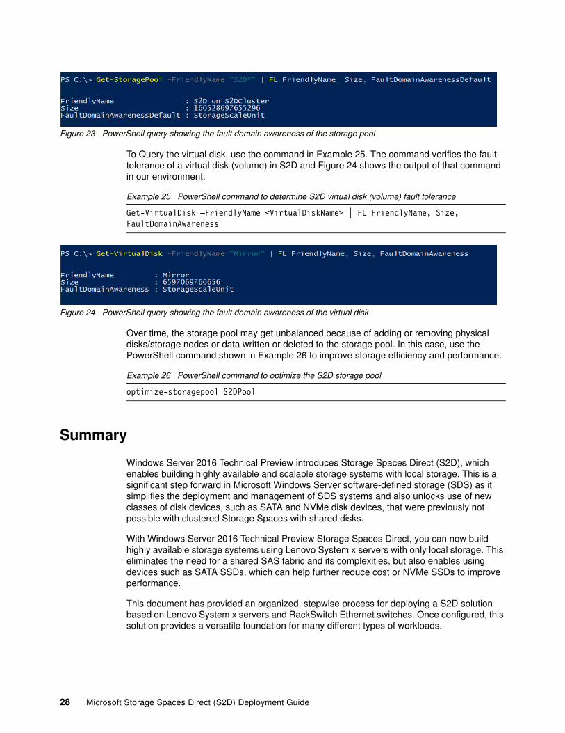
Figure 23 PowerShell query showing the fault domain awareness of the storage pool
To Query the virtual disk, use the command in Example 25. The command verifies the fault tolerance of a virtual disk (volume) in S2D and Figure 24 shows the output of that command in our environment.
Example 25 PowerShell command to determine S2D virtual disk (volume) fault tolerance
Get-VirtualDisk –FriendlyName <VirtualDiskName> | FL FriendlyName, Size, FaultDomainAwareness
Figure 24 PowerShell query showing the fault domain awareness of the virtual disk
Over time, the storage pool may get unbalanced because of adding or removing physical disks/storage nodes or data written or deleted to the storage pool. In this case, use the PowerShell command shown in Example 26 to improve storage efficiency and performance.
Example 26 PowerShell command to optimize the S2D storage pool
optimize-storagepool S2DPool
Summary
Windows Server 2016 Technical Preview introduces Storage Spaces Direct (S2D), which enables building highly available and scalable storage systems with local storage. This is a significant step forward in Microsoft Windows Server software-defined storage (SDS) as it simplifies the deployment and management of SDS systems and also unlocks use of new classes of disk devices, such as SATA and NVMe disk devices, that were previously not possible with clustered Storage Spaces with shared disks.
With Windows Server 2016 Technical Preview Storage Spaces Direct, you can now build highly available storage systems using Lenovo System x servers with only local storage. This eliminates the need for a shared SAS fabric and its complexities, but also enables using devices such as SATA SSDs, which can help further reduce cost or NVMe SSDs to improve performance.
This document has provided an organized, stepwise process for deploying a S2D solution based on Lenovo System x servers and RackSwitch Ethernet switches. Once configured, this solution provides a versatile foundation for many different types of workloads.
28 Microsoft Storage Spaces Direct (S2D) Deployment Guide

Lenovo Professional Services
Lenovo offers an extensive range of solutions, from the simple OS-only laden product to much more complex solutions running cluster and cloud technologies. For customers looking for assistance in the form of design, deploy or migrate, Lenovo Professional Services is your go-to partner.
Our worldwide team of IT Specialists and IT Architects can help customers scope and size the right solutions to meet their requirements, and then accelerate the implementation of the solution with our on-site and remote services. For customers also looking to elevate their own skill sets, our Technology Trainers can craft services that encompass solution deployment plus skills transfer, all in a single affordable package.
To inquire about our extensive service offerings and solicit information on how we can assist in your new Storage Spaces Direct implementation, please contact us at [email protected].
For more information about our service portfolio, please see our website:
http://shop.lenovo.com/us/en/systems/services/?menu-id=services
Appendix: Bill of Materials for hyperconverged solution
Table 2 lists the components of the S2D hyperconverged solution.
Table 2 Hyperconverged solution components
Part number Description Quantity
8871AC1 Server1: Lenovo System x3650 M5 4
A5EW System x 900W High Efficiency Platinum AC Power Supply 8
A483 Populate and Boot From Rear Drives 4
A5EY System Documentation and Software-US English 4
A5FV System x Enterprise Slides Kit 4
A5FX System x Enterprise 2U Cable Management Arm (CMA) 4
A5VH 4TB 7.2K 6Gbps NL SATA 3.5" G2HS HDD 40
AT9E S3710 800GB SATA 3.5" MLC HS Enterprise SSD 16
A5EA System x3650 M5 Planar 4
A5B7 16GB TruDDR4™ Memory (2Rx4, 1.2V) PC4-17000 CL15 2133MHz LP RDIMM 64
ASQA System x3650 M5 Rear 2x 2.5" HDD Label (Independent RAID-Riser1) 4
A5FH System x3650 M5 Agency Label GBM 4
ASQB System x3650 M5 Rear 2x 3.5" HDD Label 4
A5FM System x3650 M5 System Level Code 4
A2HP Configuration ID 01 8
A5FT System x3650 M5 Power Paddle Card 4
29

Change history
Changes in the 9 January 2017 update:
� Added detail regarding solution configuration if using Chelsio NICs� Added PowerShell commands for IP address assignment� Moved network interface disablement section to make more logical sense� Updated Figure 2 on page 5 and Figure 3 on page 6� Fixed reference to Intel v3 processors in Figure 4 on page 7� Updated cluster network rename section and figure� Removed Bill of Materials for disaggregated solution
9206 No Preload Specify 4
A5G1 System x3650 M5 EIA Plate 4
3U Bracket for Mellanox ConnectX-4 10 GbE Adapter 4
A5FC System x3650 M5 WW Packaging 4
A5V5 System x3650 M5 Right EIA for Storage Dense Model 4
ATET Intel Xeon Processor E5-2680 v4 14C 2.4GHz 35MB 2400MHz 120W 4
ATFJ Addl Intel Xeon Processor E5-2680 v4 14C 2.4GHz 35MB Cache 2400MHz 120W 4
5977 Select Storage devices - no configured RAID required 4
A5GH System x3650 M5 Rear 2x 2.5" HDD Kit (Independent RAID) 4
A5GE x3650 M5 12x 3.5" HS HDD Assembly Kit 4
A3YY N2215 SAS/SATA HBA 4
A45W ServeRAID M1215 SAS/SATA Controller 4
A5FF System x3650 M5 12x 3.5" Base without Power Supply 4
AT8A 600GB 10K 12Gbps SAS 2.5" G3HS HDD (AT8A) 8
A5GL System x3650 M5 Rear 2x 3.5" HDD Kit (Cascaded) 4
01GR250 Mellanox ConnectX-4 LX 10/25 GbE Dual-Port Adapter 4
5374CM1 HIPO: Configuration Instruction 4
A5M2 ServeRAID M1215 SAS/SATA Controller Upgrade Placement 4
A2HP Configuration ID 01 4
A2JX Controller 01 4
5374CM1 HIPO: Configuration Instruction 4
A2HP Configuration ID 01 4
A46U N2215 SAS/SATA HBA Placement 4
A2JY Controller 02 4
67568HG Lenovo services1: 3 Year Onsite Repair 24x7 4 Hour Response 4
Part number Description Quantity
30 Microsoft Storage Spaces Direct (S2D) Deployment Guide

Changes in the 16 September 2016 update:
� Updated process based on Windows Server 2016 RTM� Added background detail around Microsoft S2D� Added driver details for Mellanox CX-4 adapter� Added notes specific to hyperconverged vs. disaggregated deployment� Removed GUI-based Failover Cluster configuration steps (use PowerShell!)� Added step to ensure both cluster networks are available for SMB traffic to clients� Fixed issues with a couple of graphics� Updated both BOMs: the servers now use Intel Xeon E5 2600 v4 processors
Changes in the 14 July 2016 update:
� Configuration process reordered for efficiency� Added steps to configure VMQ queues� Updated and added graphics� Added various PowerShell cmdlets to aid in configuration� Fixed various typos
Changes in the 3 June 2016 update:
� Updated to list setup instructions using Windows Server 2016 TP5� Added DCB settings for each host� Updated the Bills of Material
Authors
This paper was produced by the following team of specialists:
Dave Feisthammel is a Senior Solutions Architect working at the Lenovo Center for Microsoft Technologies in Kirkland, Washington. He has over 25 years of experience in the IT field, including four years as an IBM client and 15 years working for IBM. His areas of expertise include systems management, as well as virtualization, storage, and cloud technologies.
Daniel Lu is a Senior IT Architect with Lenovo Professional Services in Kirkland, Washington. He has worked closely with the Lenovo team in Kirkland on the Microsoft Storage Space Direct solution for the past two years. His other areas of expertise include virtualization, hyper-converged and systems management.
David Ye is a Senior Solutions Architect and has been working at Lenovo Center for Microsoft Technologies for 15 years. He started his career at IBM as a Worldwide Windows Level 3 Support Engineer. In this role, he helped customers solve complex problems and was involved in many critical customer support cases. He is now a Senior Solutions Architect in the System x Enterprise Solutions Technical Services group, where he works with customers on Proof of Concepts, solution sizing, performance optimization, and solution reviews. His areas of expertise are Windows Server, SAN Storage, Virtualization, and Microsoft Exchange Server.
Michael Miller is a Windows Engineer with the Lenovo Server Lab in Kirkland, Washington. Mike has 35 years in the IT industry, primarily in client/server support and development roles. The last 10 years have been focused on Windows server operating systems and server-level hardware, particularly on operating system/hardware compatibility, advanced Windows features, and Windows test functions.
31

At Lenovo Press, we bring together experts to produce technical publications around topics of importance to you, providing information and best practices for using Lenovo products and solutions to solve IT challenges.
See a list of our most recent publications at the Lenovo Press web site:
http://lenovopress.com
32 Microsoft Storage Spaces Direct (S2D) Deployment Guide

Notices
Lenovo may not offer the products, services, or features discussed in this document in all countries. Consult your local Lenovo representative for information on the products and services currently available in your area. Any reference to a Lenovo product, program, or service is not intended to state or imply that only that Lenovo product, program, or service may be used. Any functionally equivalent product, program, or service that does not infringe any Lenovo intellectual property right may be used instead. However, it is the user's responsibility to evaluate and verify the operation of any other product, program, or service.
Lenovo may have patents or pending patent applications covering subject matter described in this document. The furnishing of this document does not give you any license to these patents. You can send license inquiries, in writing, to:
Lenovo (United States), Inc.1009 Think Place - Building OneMorrisville, NC 27560U.S.A.Attention: Lenovo Director of Licensing
LENOVO PROVIDES THIS PUBLICATION “AS IS” WITHOUT WARRANTY OF ANY KIND, EITHER EXPRESS OR IMPLIED, INCLUDING, BUT NOT LIMITED TO, THE IMPLIED WARRANTIES OF NON-INFRINGEMENT, MERCHANTABILITY OR FITNESS FOR A PARTICULAR PURPOSE. Some jurisdictions do not allow disclaimer of express or implied warranties in certain transactions, therefore, this statement may not apply to you.
This information could include technical inaccuracies or typographical errors. Changes are periodically made to the information herein; these changes will be incorporated in new editions of the publication. Lenovo may make improvements and/or changes in the product(s) and/or the program(s) described in this publication at any time without notice.
The products described in this document are not intended for use in implantation or other life support applications where malfunction may result in injury or death to persons. The information contained in this document does not affect or change Lenovo product specifications or warranties. Nothing in this document shall operate as an express or implied license or indemnity under the intellectual property rights of Lenovo or third parties. All information contained in this document was obtained in specific environments and is presented as an illustration. The result obtained in other operating environments may vary.
Lenovo may use or distribute any of the information you supply in any way it believes appropriate without incurring any obligation to you.
Any references in this publication to non-Lenovo Web sites are provided for convenience only and do not in any manner serve as an endorsement of those Web sites. The materials at those Web sites are not part of the materials for this Lenovo product, and use of those Web sites is at your own risk.
Any performance data contained herein was determined in a controlled environment. Therefore, the result obtained in other operating environments may vary significantly. Some measurements may have been made on development-level systems and there is no guarantee that these measurements will be the same on generally available systems. Furthermore, some measurements may have been estimated through extrapolation. Actual results may vary. Users of this document should verify the applicable data for their specific environment.
© Copyright Lenovo 2017. All rights reserved.Note to U.S. Government Users Restricted Rights -- Use, duplication or disclosure restricted by Global Services Administration (GSA) ADP Schedule Contract 33

This document LP0064 was created or updated on January 9, 2017.
Send us your comments via the Rate & Provide Feedback form found athttp://lenovopress.com/lp0064
Trademarks
Lenovo, the Lenovo logo, and For Those Who Do are trademarks or registered trademarks of Lenovo in the United States, other countries, or both. These and other Lenovo trademarked terms are marked on their first occurrence in this information with the appropriate symbol (® or ™), indicating US registered or common law trademarks owned by Lenovo at the time this information was published. Such trademarks may also be registered or common law trademarks in other countries. A current list of Lenovo trademarks is available on the Web at http://www.lenovo.com/legal/copytrade.html.
The following terms are trademarks of Lenovo in the United States, other countries, or both:
Lenovo®RackSwitch™Lenovo(logo)®
ServeRAID™System x®TruDDR4™
vNIC™
The following terms are trademarks of other companies:
Intel, Xeon, and the Intel logo are trademarks or registered trademarks of Intel Corporation or its subsidiaries in the United States and other countries.
Active Directory, Hyper-V, Microsoft, SQL Server, Windows, Windows Server, and the Windows logo are trademarks of Microsoft Corporation in the United States, other countries, or both.
Other company, product, or service names may be trademarks or service marks of others.
34 Microsoft Storage Spaces Direct (S2D) Deployment Guide


![Fujitsu Storage Spaces Direct · PDF fileStorage Spaces Direct – S2D Fujitsu Server PRIMERGY Platform Date: November 13, 2015 Page 2 of 62 product name] Table of Contents](https://img.pdfslide.net/doc/110x75/5a789ea67f8b9a8c428e239c/fujitsu-storage-spaces-direct-spaces-direct-s2d-fujitsu-server-primergy-platform.jpg)