Embed Size (px)
Citation preview
Specifications
Model:XK-524462-7.4V
Approved:Chunxi Zhou
Sales: Ivy Yu
Datasheet: XK-524462-7.4V1.Scope: This document describes the product specifications of rechargeable lithium ion polymer battery produced by Greenway..
2. P/N: XK-524462-7.4V
3. Parameters Index:
3.1 Parameters:
cut-off voltage, after charging with standard method.
Discharge: 0.2C to 5.5V
measure the capacity as item 4.
AC1KHz
charge-discharge cycle with standard method, then
charge to
Note: if the battery is in series, the internal resistance of PTC will change according to the temperature.
4. Performance Testing and Inspection• 4.1 Standard Testing Environment
Unless otherwise noticed, the testing should be done within month time from delivery,and the charging-recharging time should be less than 5
times. The testing conditions are as follows: Ambient Temperature: 25 ± 0.5
Ambient Humidity: 65 ± 20%
• 4.2 The Requirement of Measurements and Instrumentations
(1) The measurements and instrumentations should be approved by qualified institute.
(2) The accuracy of the size instrument is not more than 0.01mm.
(3) The accuracy of multimeter is not less than 0.5% while measure the voltage, the internal resistance mustn’t less than 10KΩ.
(4) The principal of the internal resistance is 1KHz LCR, the accuracy is 0.2%.
(5) The internal resistance is changeable; it varies according to the temperature and the charging mode. And it is relevant to the PTC and the
length and the Capacity of the drawing line.
(6) The current accuracy of the battery test system is more than ±0.1%, is obarically accuracy is ±0.5%, timer accuracy is less than ±0.1%.(7) The accuracy of the temperature meter is less than ±0.5.
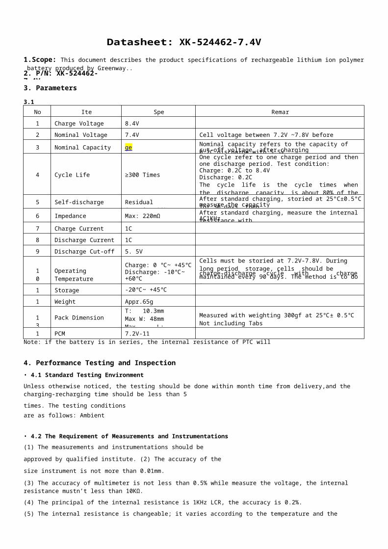
No. Item Spec Remark
1 Charge Voltage Max. 8.4V
2 Nominal Voltage 7.4V Cell voltage between 7.2V ~7.8V before shipping
3 Nominal Capacity ≥ 1400 [email protected] Nominal capacity refers to the capacity of 0.2C discharge with 5.5V
4 Cycle Life ≥300 Times
One cycle refer to one charge period and then one discharge period. Test condition:Charge: 0.2C to 8.4V
The cycle life is the cycle times when the discharge capacity is about 80% of the rated capacity.
5 Self-discharge Residual Capacity>90% After standard charging, storied at 25°C±0.5°C for 30 days, then
6 Impedance Max: 220mΩ After standard charging, measure the internal resistance with
7 Charge Current Max. 1C
8 Discharge Current Max. 1C
9 Discharge Cut-off Voltage 5. 5V
10 Operating TemperatureCharge: 0 ~ +45Discharge: -10~ +60
Cells must be storied at 7.2V-7.8V. During long period storage, cells should be maintained every 90 days. The method is to do a
7.4—7.8V.11 Storage Temperature -20~ +45
12 Weight Appr.65g
13 Pack DimensionT: 10.3mm Max W: 48mm Max L: 64.5mm Max
Measured with weighting 300gf at 25± 0.5 Not including Tabs
14 PCM 7.2V-11
• 4.3 Visual Inspection
Any visual inspection defects will affect the electronic characteristics, such as leakage, flaw, are not inexistence.
• 4.4 Charge/Discharge Methods and Test Conditions
Standard CC: 0.2C
Constant Current Charging at 0.2C to8.4V.
Quick charging time: 2 hours
Notes: The maximum charging voltage should not be more than 8.4V, and the PCM voltage designed on PCB board should not more then 9V.
• 4.5 Mechanical Characteristics
after 3 hours.
• 4.6 Safety Testing
40±2 and the relative humidity is 90%~95% .
• 4.7 Temperature Testing
capacity.
NO. Item Testing Condition and Method Standard
1 High TemperaturePut the charged battery into the high temperature box for 2 hours at55±2. And discharge the battery at 0.5C current until the voltageis 5.5V.
Discharge 90 percent of the original
2 Low TemperaturePut the charged battery into the low temperature box for 16 hours to24 hours at -10±2. And then discharge the battery at 0.1C until the voltage is 5.5V
Discharge more than45percent of the original capacity.
NO. Item Testing Condition and Method Standard
1 Over-charge Charge is conducted for 8 hours while the invariable voltage is 9V. No deformation and leakage
2 Short-circuit The charged battery is short-circuited for 1 hour at 100 mΩ. No explode or fire
3 Heat ShockPut the battery into the heat box, the temperature is rising to 120±2 at the rate of (5±2)/min and maintain for 10 minutes. Thencool down to room temperature at the rate of 5±2/min.
No explode or fire
4 Humidity and HeatPut the charged battery into box for 48 hours, the temperature is No smoke or explode
NO. Item Testing Condition and Method Standard
1 Vibration Testing
After standard charging, fixed the cell to vibration table and subjected to vibration cycling that the frequency is to be varied at the rate of 1Hz per minutes between 10Hz and 55Hz, the excursion of the vibration is 0.38mm. The cell shall be vibrated for 30 minutes fro three axis of XYZ axes.
No leakage. Left Capacity≥90%,
2 Fall Down Testing Drop the cell from 1meter height onto the concrete ground twice. No explore, no fire and no leakage
NO. Item Testing Condition and Method
1 Charging Current Quick CC: 1C
2 Standard Charging Constant Voltage Charging at 8.4V to cut-off current≤0.01C
3 Quick Charging Constant Voltage Charging at 8.4V to cut-off current≤0.01C
4 Standard Discharge Constant discharge at 1C to cut-off voltage of5.5V.
5 Charging Time Standard charging time: 6 hours
6 Temperature &HumidityStandard charging: 0~ 45 45~85% RHQuick charging: 10 ~ 45 45~85%RHStandard discharging: -10~ 60 45~85% RH
7 Open Voltage 7.2~7.8V (Before shipping)
• 4.8Electricity Maintenance
the original capacity.
5.Storage and Others• 5.1 Long Period Storage
Should the batteries have been stored for 3 months and stay unused, and then it is advisable to transfer them to a dry and cool place. Voltage at
storage should be between 7.2V and 7.8V and the storage conditions followed as item 4.1.
• 5.2 Any matters that this specification does not cover should be conferred between the customer and Greenway.
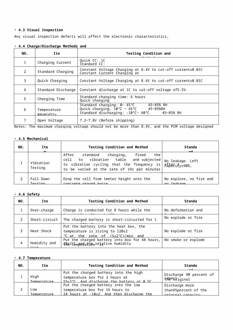
6. Mechanical Drawings:6.1 Assembly Diagram(not in scale)
PCM+PP
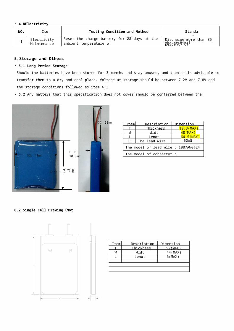
6.2 Single Cell Drawing(Not in scale)
Item Description Dimension (mm)T Thickness 52(MAX)W Width 44(MAX)L Length 6(MAX)
TC
Item Description Dimension (mm)T Thickness 10.3(MAX)W Width 48(MAX)L Length 64.5(MAX)
L1 The lead wire length 50±5
The model of lead wire : 1007AWG#24
The model of connector :
NO. Item Testing Condition and Method Standard
1 ElectricityMaintenance
Reset the charge battery for 28 days at the ambient temperature of25±0.5. And then discharge the battery until the voltage is ended.
Discharge more than 85 percent of
宽 度 :48mm
长 度 : 64 .5 m m
厚 度 :10.3mm
线长:50mm
Handling Precaution and Guide line for Lithium-Ion Polymer Rechargeable Batteries
This document of ‘handling precautions and guideline for rechargeable batteries’ shall be applied to the battery cells manufactured by Greenway.
It is advisable to contact Greenway in advance if and when the customer needs other applications of operating conditions than those described in this
document. Additional experimentation may be required to verify performance and safety under such condition. Greenway will take no responsibility
for any accident when the cell is used under other condition. Greenway will inform, in a written form, the customers of improvement(s) regarding
proper use and handling of the cell, if it is deemed necessary.
1. Charging1. 1Charging Current:
Charging current should be less than maximum charge current specified in the Specification Approval Sheet.
1.2 Charging Voltage:Charging voltage should be less than the maximum nominal voltage 8.4V, and the charging voltage upper limited is 8.60V(single pack).
1.3 Charging Temperature:
The cell should be charged within the range specified in this Specification Approval Sheet.
1.4 Notes:
Since charging with constant current or constant voltage, reverse charging is prohibited. In case of the cell is connected improperly, the cell
cannot be charged. Simultaneously, the reverse charging may cause damaging to the cell which may lead to degradation of cell performance and
damage the cell safety, and could cause heat generation or leakage.
2. Discharging Current:The cell shall be discharged at less than the maximum discharge current specified in the Specification Approval Sheet. High discharging
current may reduce the discharging capacity significantly or cause over-heat.
3. Discharging TemperatureDischarging Temperature should be within the range specified in this Specification Approval Sheet.
4.Over-DischargeOver-discharging will cause cell low-performance and function loss. The cell would be in a over-discharged state by its self-discharge
characteristic. In order to prevent over-discharging, the cell shall be charged periodically to maintain between 7.2V and 7.8V.
5. Protective Circuit Module (PCM)5.1 The cell / battery pack shall be with a PCM that can protect cell / battery pack properly. PCM shall have functions of
Overcharge prevention
Over-discharge prevention
Over current prevention to maintain safety and prevent significant deterioration of cell performance. The over current can occur by external
short circuit.
5.2 Overcharge Protection
Overcharging prevention function shall stop charging if any cell of the battery pack reaches 8.60V.
5.3 Over-discharge Protection
Over-discharging protection function shall monitor the voltage of every cell in the pack, and work to avoid further drop in the cell voltage of
10V or less.
6. StorageCells should be stored in proper temperature specified in datasheet.
7. Notice!
7.1 Handling of Cells:
Avoid any short-circuit; it will cause the pole hot and lost electronic functions.
Soft packing is very damaged by sharp edge parts such as needles and knives. Avoid cells touch with sharp edge part, when handling
and storage.
Beside the poles is the sealed edge. Don’t bend or fold dealing edge, for it is a sensitive part.
Don’t open the folding edge on both sides of the cells.
Don’t bend the tabs, for the tabs are not so stubborn.
Avoid mechanical shock to the cells.
Don’t put the cells into the heater, washing machine or high-voltage container.
Don’t use the charger without any safety guarantee, and recommend you use specified charger.
You should immediately stop charging, as cell is overheating, delivery any smell, changed color, distortion etc.
Before Children use batteries, adults should explain the usage first.
Before use batteries, please read the handling guideline carefully and fully understand.
Away from the static-electronic field, while using, charging and storing cells.
Don’t put the cells together with metal conductors such as chains, barrette, bolt into the pocket or stored them together.
Don’t use metal conductor to shortcut the positive and negative poles.
Don’t mis-assemble the positive pole with the negative one.
7.2 Notice for Designing Battery Pack
7.2.1 Package Design① Battery pack should have sufficient strength and battery should be protected from mechanical shock.② No sharp edge components should be inside the pack containing the battery.
7.2.2 PCM Design① The overcharge threshold voltage should not be exceed 8.5V (single pack)② The over-discharge threshold voltage should not be lower than 4.80V (single pack)③ The PCM should have short protection built inside.
7.3 Notices for Assembling Battery Pack
7.3.1 Tab Connection① Ultrasonic welding or spot welding is recommended to connect battery with PCM or other parts.② If apply manual solder method to connect tab with PCM, below notice is very important to ensure battery performance.
a.
b.
c.
d.
e.
The solder iron should be temperature controlled and ESD safe.Soldering temperature should not exceed 350.
Soldering time should not be longer than 3 seconds
Keep battery tab cold down before next time soldering.Directly heat cell body is strictly prohibited. Battery should be damaged by heat above approx. 60
7.3.2 Cell Fixing① The battery should be fixed to the battery pack by its large surface area.② No sharp edge at the assembling position.③ No cell movement in the battery pack should be allowed.
8.Others
8.1 The disassembling may generate internal shout circuit in the cell, which may cause gassing, firing, or other problem.
8.2 Prohibition Of Disposing Cells of Fire
Never incinerate or dispose the cells of fire, for these may cause burning of the cells.
8.3 The cells should never be soaked with liquids such as water, drinks or oil.
8.4 Prohibit using the cells mixed with different manufactories. Prohibit using new cells mixed with old ones.
Special Notice: Keep the cells in half-charged state, which is keeping them fully charged or completely discharged. Storing the cells in cool and dry place
Appendix
1. Electrical Characteristics
DET1
REL1
DET2
REL2
DET3
DS
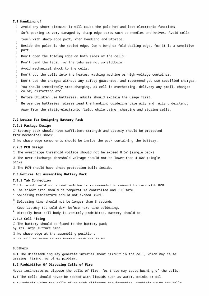
2. BOM of PCB
No. Location Part name Specification Pack type Q’ty Maker/Remark
1 U1
Battery
Protection
Ic
S-8232AUFT 8Pin-TSSOP 1SII,
Or equivalent
2 U2Silicon
MOSFET6876 TSOP-8 1 FDS
3R1, R2, R3,
R4,Resistance SMD 1KΩ±5% 0603 4
SKYWELL
Or equivalent
4 R5 Resistance SMD 4.7MΩ±5% 0603 1SKYWELL
Or equivalent
5
C1,C2,
C3,C4, Capacitance SMD 0.1uF/50V 0603 4SKYWELL
Or equivalent
6 C5 Capacitance SMD 2.250V 0603 1SKYWELL
Or equivalent
7 PCB PCB 46.8mm×5±0.2×0.6m m
0.3mm ±
0.15mm
1 ASSUN/FR4
Item Symbol Content Criterion
Over Charge Protection
V Over charge detection voltage 4.30±0.025V*2
tCU Over charge detection delay time 0.96s to 1.4s
V Over charge release voltage 4.10±0.05V*2
Over Discharge Protection
V Over discharge detection voltage 2.40±0.08V*2tDL Over discharge detection delay time 115ms-173ms
V Over discharge release voltage 3.0±0.1V*2
Over Current Protection
V Over current detection voltage 0.2±0.015V
IDP Over current detection current 3~5A
Tiov1 Over current detection delay time 7.2ms to 11ms
Release condition Cut load
Short Protection
Detection Condition Exterior short circuit
Release condition Cut short circuit
Tiov2 Shot circuit detection delay time 220-380Us
Interior Resistance R Main loop electrify resistance VC=8.4V,RDS
≤60Mω
Current Consumption IDD Current consume in normal operation 7µA Typ. 14.0µA Max
0V battery charging function Unavailable
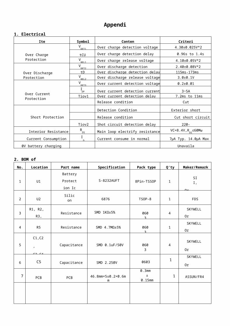
3. Application Circuit
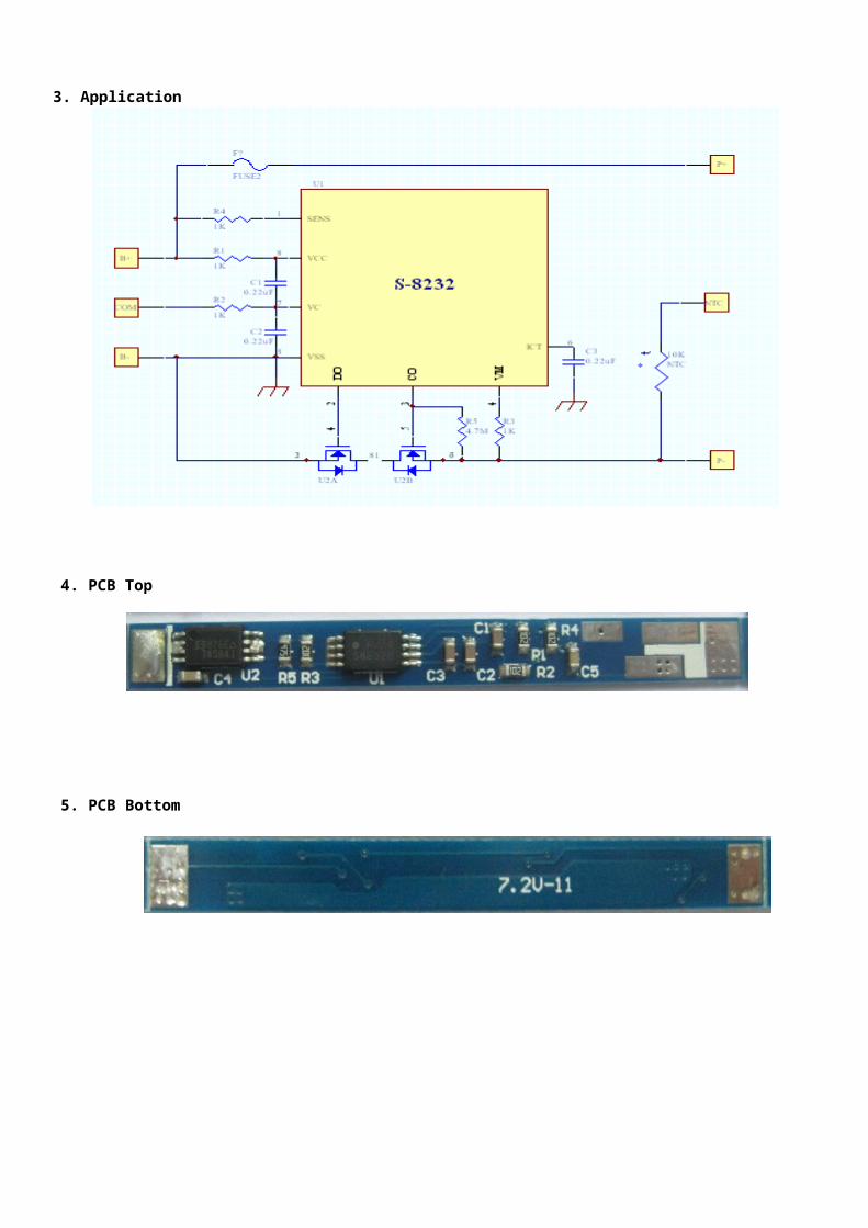
4. PCB Top Layer
5. PCB Bottom Layer

6. Absolute Maximum Ratings:Parameter Rating Unit
Operating Temperature Range -30~+70
Operating Humidity Range Less than 85% RH %RH
Storage Temperature Range -45~+85
Storage Humidity Range Less than 85% RH %RH
Voltage Between Terminals Of P+ and P- 20.0 V
Voltage Between Terminals Of B+ and B- 20.0 V

Copyright Reserved @ 2007 Shenzhen Xingke Professional Li-ion Battery Co., Ltd. Page 11 of 11