Embed Size (px)
Citation preview
Draft AIS-118/D4June 2012
DRAFT
AUTOMOTIVE INDUSTRY STANDARD
Automotive Vehicles - Safety Glazing Materials for
Motor Vehicles - Method of Test andRequirements
ARAI
Page 1 of 73

REL E AS E S
1. AIS 118 - D1: 22.06.2010
2. AIS118 – D2 : 20.12.2010
3. AIS 118 – D3: 24.05.2011
4. AIS 118 – D4: 20.06.2012
5. AIS118 – F :
• Nil• Nil
Draft AIS-118/D4June 2012
Page 2 of 73
Draft AIS-118/D4June 2012
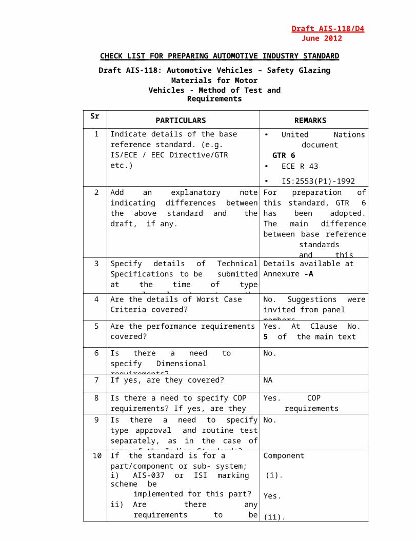
C HECK L I S T FOR PREP A RING A U TOMOT I VE I N D U S T RY ST A ND A RD
Draft AIS-118: Automotive Vehicles – Safety Glazing Materials for MotorVehicles - Method of Test and Requirements
Sr. No. PARTICULARS REMARKS
1 Indicate details of the base reference standard. (e.g. IS/ECE / EEC Directive/GTR etc.)
• United Nations documentGTR 6
• ECE R 43
• IS:2553(P1)-1992
• IS:2553(P2)-1992
2 Add an explanatory note indicating differences between the above standard and the draft, if any.
For preparation of this standard, GTR 6 has been adopted. The main difference between base reference standards and this standard is that some additional tests have been added to make in-line with GTR 6.
3 Specify details of Technical Specifications to be submitted at the time of type approval relevant to the requirements of this standard covered.
Details available at Annexure -A
4 Are the details of Worst Case Criteria covered? No. Suggestions were invited from panel members.
5 Are the performance requirements covered? Yes. At Clause No. 5 of the main text
6 Is there a need to specify Dimensional requirements?
No.
7 If yes, are they covered? NA
8 Is there a need to specify COP requirements? If yes, are they covered?
Yes. COP requirements are covered.
9 Is there a need to specify type approval and routine test separately, as in the case of some of the Indian Standards?If yes, are they covered?
No.
10 If the standard is for a part/component or sub- system;i) AIS-037 or ISI marking scheme be
implemented for this part?ii) Are there any requirements to be
covered for this part when fitted on the vehicle?
If yes, has a separate standard been prepared?
Component
(i). Yes.
(ii). No.
NAPage 3 of 73

Draft AIS-118/D4June 2012
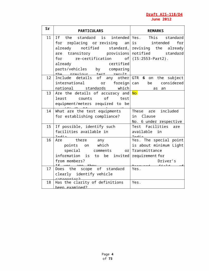
Sr. No. PARTICULARS REMARKS
11 If the standard is intended for replacing or revising an already notified standard, are transitory provisions for re-certification of already certified parts/vehicles by comparing the previous test result, certain additional test, etc. required?
If yes, are they included?
Yes. This standard is intended for revising the already notified standard (IS:2553-Part2).
Yes. Additional Tests have been covered in Transitional Provision (Clause No. 12.0).
12 Include details of any other international or foreign national standards which could be considered as alternate standard.
GTR 6 on the subject can be considered as an alternate standard.
13 Are the details of accuracy and least counts of test equipment/meters required to be specified? If yes, have they been included?
No.
14 What are the test equipments for establishing compliance?
These are included in ClauseNo. 6 under respective Test(s).
15 If possible, identify such facilities available inIndia.
Test Facilities are available inIndia.
16 Are there any points on which special comments or information is to be invited from members?If yes, are they identified?
Yes. The special point is about minimum Light Transmittance requirement for Driver’s Rearward Field of Vision (refer Clause No. 5.1.1.2)
17 Does the scope of standard clearly identify vehicle categories?
Yes.
18 Has the clarity of definitions been examined? Yes.
Page 4 of 73
INTRODUCTION
Draft AIS-118/D4June 2012
The Government of India felt the need for a permanent agency to expedite the publication of standards and development of test facilities in parallel when the work on the preparation of the standards is going on, as the development of improved safety critical parts can be undertaken only after the publication of the standard and commissioning of test facilities. To this end, Ministry of Surface Transport (MOST) has constituted a permanent Automotive Industry Standard Committee (AISC) vide order No. RT-11028/11/97-MVL dated September 15, 1997. The standards prepared by AISC will be approved by the permanent CMVR Technical Standing Committee (CTSC). After approval, the Automotive Research Association of India, (ARAI), Pune, being the secretariat of the AIS Committee, has published this standard. For better dissemination of this information ARAI may publish this document on their web site.
In the Contemporary Automotive Industries, various types of Safety Glazing materials are being used globally. Therefore it is a critical safety component which is widely intended for Windscreens of wheeled vehicles.
While formulating this standard, considerable assistance has been taken from the following National and International standards/Regulations:-
IS: 2553 (Part1) - 1990: Safety Glass Specification (General Purpose)
IS: 2553 (Part2) – 1990: Safety Glass Specification (For RoadTransport).
ECE R43 : Uniform Provisions for Concerning the Approval of Safety Glazing Materials and their Installation on Vehicles.
GTR No. 6 : Safety Glazing Materials for Motor Vehicles and Motor Vehicle Equipments.
The Composition of Panel and AIS Committee responsible for preparation of this standard has been given at Annex B and Annex C respectively (To be included).
Page 5 of 73

Draft AIS-118/D4June 2012
Automotive Vehicles - Safety Glazing Materials forMotor Vehicles- Method of Test and Requirements
1. PURPOSE
1.1 This regulation specifies the requirements for Safety Glazing intended for installation in motor vehicles as original equipment or as replacement parts. Its purpose is:
a) To reduce the danger of bodily injury as far as possible in the event of shattering of a vehicle window;
b) To ensure that vehicle windows are sufficiently resistant to the incidents likely to occur in normal traffic, and to atmospheric and temperature conditions, chemical action, combustion and abrasion;
c) To ensure that windscreens are sufficiently transparent to ensure driver visibility and to allow the driver to see the road clearly enough to be able to brake and stop the vehicle in the event of windscreen shattering;
d) To minimize the possibility of occupants being thrown through vehicle windows in collisions.
1.2 SCOPE
This regulation applies to safety glazing intended for installation as windscreens, window panes on Category 1 M, and 2 N and L category (with bodywork at least partially covering the driver) vehicles as defined in Special Resolution No. 1 (S.R.1) AIS 053 concerning the Classification of vehicles Co mmo n Definitions of Vehicle Categor ies, Masses and D ime ns ions , to the exclusion ho wever of glazing for lighting and light-signaling devices and instrument panels, plastic windows of soft top vehicles and of bullet resistant glazing. In the case of double windows, each pane is considered a separate item of glazing.
2. REFERENCES
2.1 The following Standards/Regulations were referred while preparing this standard:
2.1.1 United Nations document ECE/TRANS/WP.29/AC.3/9 & ECE/TRANS/WP29/1047. These documents are the GTR text for Safety Glazing.
2.1.2 ECE R43 - Uniform Provisions for Concerning the Approval of SafetyGlazing Materials and their Installation on Vehicles.
Page 6 of 73
Draft AIS-118/D4June 2012
2.1.3 GTR No. 6 – Safety Glazing Materials for Motor Vehicles and MotorVehicles Equipments.
2.1.4 IS:2553 (Part2): 1990 – Safety Glass Specifications (Road Transport)
2.1.5 IS:2553 (Part1): 1990 – Safety Glass Specifications (GeneralPurpose)
2.1.6 ISO 6549:1999 - Road vehicles -- Procedure for H- and R-point determination
2.1.7 ISO 4130:1978 - Road vehicles -- Three-dimensional reference system and fiducial marks -- Definitions
3. DEFINITIONS
3.1 Bullet resistant glazing means glazing constructed so as to be resistant to firearms.
3.2 Design glass outline means the design maximum unobstructed vehicle aperture designated to be glazed, before the glazing is installed or mounted, including all trims, but excluding obscuration bands.
3.3 Glazing means, for purposes of this standard, the following materials.
3.3.1 Double-glazed unit means an assembly of two panes permanently assembled in manufacture and separated by a gap.
3.3.1.1 Symmetrical double-glazed unit means a double-glazed unit where the two component panes are identical (e.g., both toughened glass).
3.3.1.2 Asymmetrical double-glazed unit means a double-glazed unit where the two component panes are not identical (e.g., one is toughened glass and the other is laminated glass).
3.3.2 Double window means an assembly of two individual panes separately installed within the same opening in the vehicle.
3.3.3 Glass-plastics mean glazing consisting of any glazing material which comprises one layer of glass and one or more layers of plastic in which a plastic surface of the product faces the inner side.
3.3.4 Interlayer: means any material designed to be used to hold together the component layers of laminated-glass.
Page 7 of 73
Draft AIS-118/D4June 2012
3.3.5 Laminated-glass: means glazing consisting of two or more layers of glass held together by one or more inter-layers of plastic material.
3.3.6 Glazing faced with plastics: means a glass pane either toughened- glass or laminated-glass with a layer of plastic on the inner side.
3.3.7 Uniform Toughened Glass: means glazing consisting of a single layer of glass which has been subjected to special treatment to increase its mechanical strength and to condition its fragmentation after shattering.
3.3.8 Plastic Glazing is a glazing material that contains as an essential ingredient one or more organic polymeric substances of large molecular weight, is solid in its finished state and, at some stage in its manufacture of processing into finished articles, can be shaped by flow;
3.3.8.1 Rigid Plastic Glazing means a plastic glazing material which does not deflect vertically more than 50mm in the flexibility test.
3.3.8.2 Flexible Plastic Glazing means a plastic glazing material which deflects vertically more than 50mm in the flexibility test.
3.4 Glazing Requisite for Driver Visibility:
3.4.1 G l azing r e q uisite for t h e dr i v e r 's for w a rd fie l d of vision : means all the glazing forward of a plane passing through the driver's "R" point and perpendicular to the longitudinal median plane of the vehicle, through which the driver can, is able to view the road when driving or manoeuvring the vehicle.
3.4.2 G l azing re q uisi t e for t h e dri v er's r e arward field of vision : means all glazing rearward of a plane passing through the driver's "R" point and perpendicular to the longitudinal median plane of the vehicle, through which the driver can, is able to view the road when driving or manoeuvring the vehicle.
3.5 Height of segment "h": means the maximum distance, measured at right angles to the glazing, separating the inner surface of the glazing from a plane passing through the ends of the glazing.(see 7.2, Figure 1)
3.6 Inner side: means the side of glazing which is facing towards the passenger/driver compartment when the material is mounted in the vehicle.
3.7 Nominal thickness: means the manufacturer's design thickness with a tolerance of ± (n x 0.2 mm) where n equals the number of glass layers in the glazing.
3.8 Opaque obscuration: means any area of the glazing preventing light transmission, including any screen-printed area, whether solid or dot-
printed, but excluding any shade band.
3.9 Optical Deviation means the angle between the true and the apparent direction of a point viewed through the windscreen, the magnitude of the angle being a function of the angle of incidence of the line of sight, the thickness and inclination of the windscreen, and the radius ofcurvature "r" at the point of incidence.
Page 8 of 73
Draft AIS-118/D4June 2012
3.10 Optical Distortion means an optical defect in a windscreen that changes the appearance of an object viewed through the windscreen.
3.11 Outer side means the side of glazing which is facing away from the passenger/ driver compartment when the material is mounted in the vehicle.
3.12 Pane means any single piece of glazing other than a windscreen.
3.12.1 Curved pane means a pane with a height of segment "h" (see 7.2)greater than 10 mm per linear meter.
3.12.2 Flat pane means a pane with a height of segment "h" (see 7.2) equal to or less than 10 mm per linear meter.
3.13 Reference Points
3.13.1 Eye-Point means the "O" Point.
3.13.2 "H" Point means the pivot centre of the torso and thigh of the 3 DH machine installed in the vehicle seat. The 3 DH machine corresponds to that described in ISO Standard 6549. The coordinates of the H point are determined in relation to the fiducial marks defined by the vehicle manufacturer, according to the three-dimensional system corresponding to ISO Standard 4130.
3.13.3 "O" Point means the point located 625 mm above the "R" Point of the driver's seat in the vertical plane parallel to the longitudinal median plane of the vehicle for which the windscreen is intended, passing through the axis of the steering wheel.
3.13.4 "R" Point or seating reference point means the position of the H-point with the driver's seat in the design driving position as defined by the vehicle manufacturer.
3.13.5 Design seat-back angle means the angle between the vertical line through the R point and the torso line defined by the vehicle manufacturer.
3.14 Radius of curvature "r" means the smallest radius of arc of the glazing as measured in the most curved area.
3.15 Regular light transmittance means light transmittance measured perpendicularly to the glazing.
Page 9 of 73
Draft AIS-118/D4June 2012
3.16 Sample means a specially prepared piece of glazing representative of a finished product or a piece cut from a finished product.
3.17 Secondary image means a spurious or ghost image, in addition to the bright primary image, usually seen at night when the object being viewed is very bright in relation to its surroundings, for example, the headlights of an approaching vehicle.
3.18 Secondary image separation means the angular distance between the position of the primary and secondary images.
3.19 Shade band means any area of the glazing with a reduced light transmittance, excluding any opaque obscuration.
3.20 Test piece means a sample or a finished product of glazing.
3.21 Transparent area of the windscreen means the glazing area contained within the design glass outline, excluding any allowed opaque obscuration (see 7.1.3.4.), but including any shade band.
3.22 Windscreen means the glazing in front of the driver through which the driver views the road ahead.
3.22.1 Inclination angle of a windscreen means the angle included between a vertical line and a straight line passing through the top and bottom edges of the inner side of the windscreen, when both lines are contained in the vertical plane through the longitudinal axis of the vehicle.
3.23 Type of safety glazing material means a glazing not exhibiting any essential differences, with respect, in particular, to the principal and secondary characteristics;
3.23.1 Although a change in the principal characteristics implies that the product is of a new type, it is recognized that in certain cases a change in shape and dimension does not necessarily require a complete set of tests to be carried out. For certain of the tests prescribed in the individual annexes, glazings may be grouped if it is evident that they have similar principal characteristics;
3.23.2 Types of glazing exhibiting differences only as regards their secondary characteristics may be deemed to be of the same type; certain tests may however be carried out on samples of such glazings if the performanceof those tests is explicitly stipulated in the test condition.
Page 10 of 73
Draft AIS-118/D4June 2012
4 General Requirements
4.1 Markings
4.1.1 General Requirements for Markings.
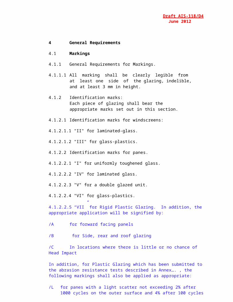
4.1.1.1 All marking shall be clearly legible from at least one side of the glazing, indelible, and at least 3 mm in height.
4.1.2 Identification marks:Each piece of glazing shall bear the appropriate marks set out in this section.
4.1.2.1 Identification marks for windscreens:
4.1.2.1.1 "II" for laminated-glass.
4.1.2.1.2 "III" for glass-plastics.
4.1.2.2 Identification marks for panes.
4.1.2.2.1 "I" for uniformly toughened glass.
4.1.2.2.2 "IV" for laminated glass.
4.1.2.2.3 "V" for a double glazed unit.
4.1.2.2.4 "VI" for glass-plastics.
4.1.2.2.5 “VII” for Rigid Plastic Glazing. In addition, the appropriate application will be signified by:
/A for forward facing panels
/B for Side, rear and roof glazing
/C In locations where there is little or no chance of Head Impact
In addition, for Plastic Glazing which has been submitted to the abrasion resistance tests described in Annex…. , the following markings shall also be applied as appropriate:
/L for panes with a light scatter not exceeding 2% after 1000 cycles on the outer surface and 4% after 100 cycles on the inner surface (See Annex…
/M for panes with a light scatter not exceeding 10% after 500 cycles on the outer surface and 4% after 100 cycles on the inner surface.(See Annex…
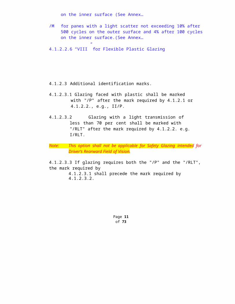
4.1.2.2.6 “VIII” for Flexible Plastic Glazing
4.1.2.3 Additional identification marks.
4.1.2.3.1 Glazing faced with plastic shall be marked with "/P" after the mark required by 4.1.2.1 or 4.1.2.2., e.g., II/P.
4.1.2.3.2 Glazing with a light transmission of less than 70 per cent shall be marked with "/RLT" after the mark required by 4.1.2.2. e.g. I/RLT.
Note: This option shall not be applicable for Safety Glazing intended forDriver’s Rearward Field of Vision.
4.1.2.3.3 If glazing requires both the "/P" and the "/RLT", the mark required by4.1.2.3.1 shall precede the mark required by 4.1.2.3.2.
Page 11 of 73
Draft AIS-118/D4June 2012
4.2 P articu lar P rovisions
4.2.1 Installation
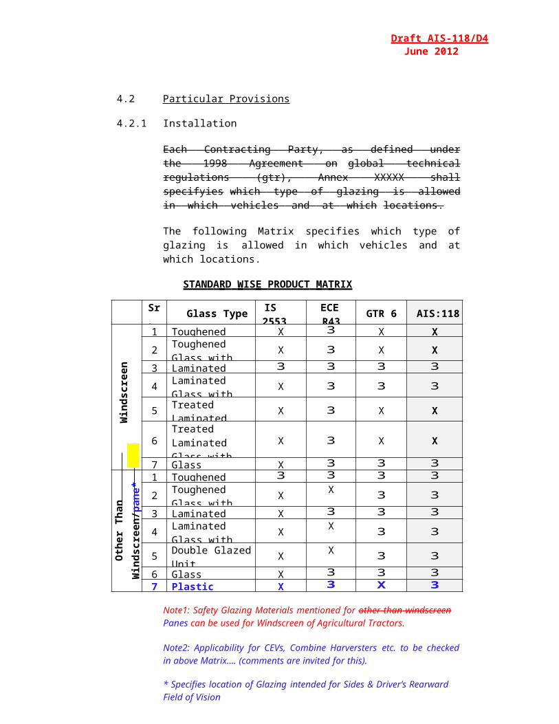
Each Con tr acting P arty , as d efin ed under the 199 8 A greemen t on global technical regulations (gtr), A nnex X XXXX shall specify ies w hich ty pe of glazing is al lowed in which v ehicles an d at which locations.
The following Matrix specifies which type of glazing is allowed in which vehicles and at which locations.
STANDA RD WIS E PRODUCT MA TRIX
Sr. No. Glass Type IS 2553
(P1 & 2)ECE R43 GTR 6 AIS:118
Win
dscr
een
1 Toughened Glass X 3 X X
2 Toughened Glass with Plastic face X 3 X X
3 Laminated Glass 3 3 3 3
4 Laminated Glass with Plastic face X 3 3 3
5 Treated LaminatedGlass X 3 X X
6Treated Laminated Glass with Plastic face
X 3 X X
7 Glass Plastics X 3 3 3
Oth
er T
han
Win
dscr
een/
pane
*
1 Toughened Glass 3 3 3 3
2 Toughened Glass with Plastic face X X 3 3
3 Laminated Glass X 3 3 3
4 Laminated Glass with Plastic face X X 3 3
5 Double GlazedUnit X X 3 3
6 Glass Plastics X 3 3 37 Plastic Glazing X 3 X 3
Note1: Safety Glazing Materials mentioned for oth er tha n winds cr een Panes can be used for Windscreen of Agricultural Tractors.
Note2: Applicability for CEVs, Combine Harversters etc. to be checked in above Matrix…. (comments are invited for this).
* Specifies location of Glazing intended for Sides & Driver’s Rearward Field of Vision
Page 12 of 73
Draft AIS-118/D4June 2012
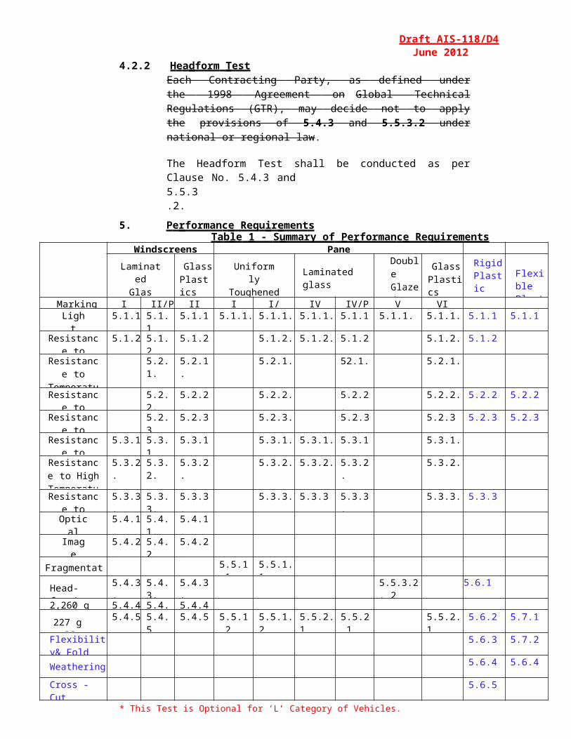
4.2.2 Hea dform TestEa ch C on tra ct ing P ar ty, as def ined under th e 1998 A greemen t o n G lo bal Te chn ical Regu lations (G TR), may decid e not to apply the prov is io ns of 5.4.3 and 5.5.3.2 under nation al or region al law.
The Headform Test shall be conducted as per Clause No. 5.4.3 and5.5.3.2.
5. Pe rformanc e Requ ir ementsTab le 1 - S ummary of Pe rformanc e Req uirements
Windscreens Panes
LaminatedGlass
GlassPlastics
UniformlyToughened Glass Laminated glass
Double Glazed Unit 1/
GlassPlastics
Rigid Plastic
Flexible Plastic
Marking II II/P III I I/P IV IV/P V VILight
Transmittance5.1.1. 5.1.1. 5.1.1. 5.1.1. 5.1.1. 5.1.1. 5.1.1. 5.1.1. 5.1.1. 5.1.1 5.1.1
Resistance toAbrasion
5.1.2. 5.1.2. 5.1.2. 5.1.2. 5.1.2. 5.1.2. 5.1.2. 5.1.2
Resistance to Temperature
Changes
5.2.1. 5.2.1. 5.2.1. 52.1. 5.2.1.
Resistance toFire
5.2.2. 5.2.2. 5.2.2. 5.2.2. 5.2.2. 5.2.2 5.2.2
Resistance toChemicals
5.2.3 5.2.3. 5.2.3. 5.2.3 5.2.3 5.2.3 5.2.3
Resistance toRadiation
5.3.1. 5.3.1. 5.3.1. 5.3.1. 5.3.1. 5.3.1. 5.3.1.
Resistance to High
Temperature
5.3.2. 5.3.2. 5.3.2. 5.3.2. 5.3.2. 5.3.2. 5.3.2.
Resistance toHumidity
5.3.3. 5.3.3. 5.3.3. 5.3.3. 5.3.3 5.3.3. 5.3.3. 5.3.3
OpticalDistortion
5.4.1. 5.4.1. 5.4.1.
ImageSeparation
5.4.2. 5.4.2. 5.4.2.
Fragmentation 5.5.1.1. 5.5.1.1.
Head-form* 5.4.3. 5.4.3. 5.4.3. 5.5.3.2. 2/
5.6.1
2,260 g Ball 5.4.4. 5.4.4. 5.4.4.
227 g Ball 5.4.5. 5.4.5. 5.4.5. 5.5.1.2. 5.5.1.2. 5.5.2.1. 5.5.2.1.
5.5.2.1 5.6.2 5.7.1
Flexibility& Fold
5.6.3 5.7.2
Weathering 5.6.4 5.6.4
Cross - Cut 5.6.5
* This Test is Optional for ‘L’ Category of Vehicles.1 / Each component pane shall satisfy the appropriate tests for the type of glazing.
Page 13 of 73
Requ ire men ts app lic able to A ll Gla zi ng
Draft AIS-118/D4June 2012
5.1.1 Ligh t Transm ittance T es t
5.1.1.1 When tested in accordance with 6.11, the regular light transmittance of glazing requisite for the Driver's Forward Field of Vision shall not be less than 70%.
5.1.1.2 When tested in accordance with 6.11., the regular light transmittance of glazing requisite for the Driver's Rearward Field of Vision may shall not be less than 70%, if not forbidd en by the nation al legis latio n or regulat io n of Con tract ing P ar ty . (Comments are required for this Clause)
5.1.1.3 Test Pieces
5.1.1.3.1 Three test pieces shall be tested and each shall meet the requirements.
5.1.1.3.2 The test pieces shall be as described in 6.11.3.
5.1.2 Tes t of Resis tance to Ab ra sion
5.1.2.1 Except as provided in 5.1.2.2., when tested in accordance with 6.6. for1,000 cycles, light scatter shall not exceed 2%.
5.1.2.2 For glazing faced with plastic, when tested on the inner side in accordance with 6.6. for 100 cycles, light scatter shall not exceed 4%.
5.1.2.3 For Rigid Plastic glazing, when tested in accordance with 6.6 for 1000, 500 or 100 cycles to measure abrasion of the surface of the product.
5.1.2.3.1 In case of Rigid Plastics of CLASS L, the abrasion test shall be considered to have given a satisfactory result if the total light scatter after abrasion does not exceed 2% after 1000 cycles on the outer surface of the test sample and 4% after 100 cycles on the inner surface of the test sample.
5.1.2.3.2 In case of Rigid Plastics of CLASS M, the abrasion test shall be considered to have given a satisfactory result if the total light scatter after abrasion does not exceed 10% after 500 cycles on the outer surface of the test sample and 4% after 100 cycles on the inner surface of the test sample.
5.1.2.4 Test Pieces
5.1.2.4.1 Three test pieces shall be tested and each shall meet the requirements.
5.1.2.4.2 The test pieces shall be as described in 6.6.3.
5.2 Requ ire men ts app lic able to all gl azin g faced with plas ti c
5.2.1 Tes t of Resi st ance to Te mperature Ch anges
5.2.1.1 When tested in accordance with 6.10. the test pieces shall not show any evidence of cracking, clouding, separation of layers or apparent deterioration.
5.2.1.2 Test Pieces
5.2.1.2.1 Two test pieces shall be tested and each shall meet the requirements.
5.2.1.2.2 The test pieces shall be as described in 6.10.2.
Page 14 of 73
Draft AIS-118/D4 June 2012
5.2.2 Tes t of Resi st ance to Fir e
5.2.2.1 When tested in accordance with 6.14, the rate of burning shall not exceed 90 mm/min.
5.2.2.2 Test Pieces
5.2.2.2.1 Five test pieces shall be tested and each shall meet the requirements.
5.2.2.2.2 The test pieces shall be as described in 6.14.
5.2.3 Tes t of Resi st ance to Ch em icals
5.2.3.1 When tested in accordance with 6.15. the test piece shall not exhibit any softening, tackiness, crazing, or apparent loss of transparency.
5.2.3.2 Test Pieces
5.2.3.2.1 Four test pieces per chemical shall be tested and at least three shall meet the requirements.
5.2.3.2.2 The test pieces shall be as described in 6.15.
5.3 Re q u i re m e n ts a pp l ic a b le to a ll la m in at e d- g l a ss a nd a l l g l a z ing f a ced with plastics, Glass Plastics
5.3.1 Tes t of Resi st ance to Rad ia tion
5.3.1.1 When tested in accordance with 6.8., the total light transmittance when measured pursuant to paragraph 6.11. shall not fall below 95% of the original value before irradiation and for glazing required to have a minimum light transmittance of 70 %, shall not fall below 70 %.
5.3.1.2 Test Pieces
5.3.1.2.1 Three test pieces shall be tested and each shall meet the requirements.
5.3.1.2.2 The test pieces shall be as described in 6.8.3.
5.3.2 Tes t of Resi st ance to High Temper ature
5.3.2.1 When tested in accordance with 6.7, no significant change, e.g. whitening, bubbles, or delamination, excepting surface cracks, shall form more than 15 mm from an uncut edge or 25 mm from a cut edge of the test piece or sample or more than 10 mm away from any crackswhich may occur during the test.
Page 15 of 73
Draft AIS-118/D4June 2012
5.3.2.2 Test Pieces
5.3.2.2.1 Three test pieces shall be tested and each shall meet the requirements.
5.3.2.2.2 The test pieces shall be as described in 6.7.2.
5.3.3 Tes t of Resi st ance to Humidity
5.3.3.1 When tested in accordance with 6.9, at the time specified in 6.9.1.4 or6.9.1.5, as appropriate, no significant change, e.g., whitening, bubbles, or delamination, excepting surface cracks, shall be observed more than10 mm from the uncut edges and more than 15 mm from the cut edges.
5.3.3.2 Additionally, for Plastic Glazing, the light transmittance does not fall to less than 95% of the pre-test value and additionally to no less than 70% for any window required for driver visibility.
5.3.3.3 For Plastic Glazing: After testing , the test pieces shall be stored for atleast 48h at a temperature of 23 ± 2°C and a relative humidity of 50 ± 5% and then subjected to the 227g ball drop test described under 6.16
5.3.3.2 Test Pieces
5.3.3.2.1 Three test pieces shall be tested and each shall meet the requirements.
5.3.3.2.2 The test pieces shall be as described in 6.9.2.
5.4 Requ ire men ts app lic able to W in dscre ens
5.4.1 Opt ical Dis to rtion Test
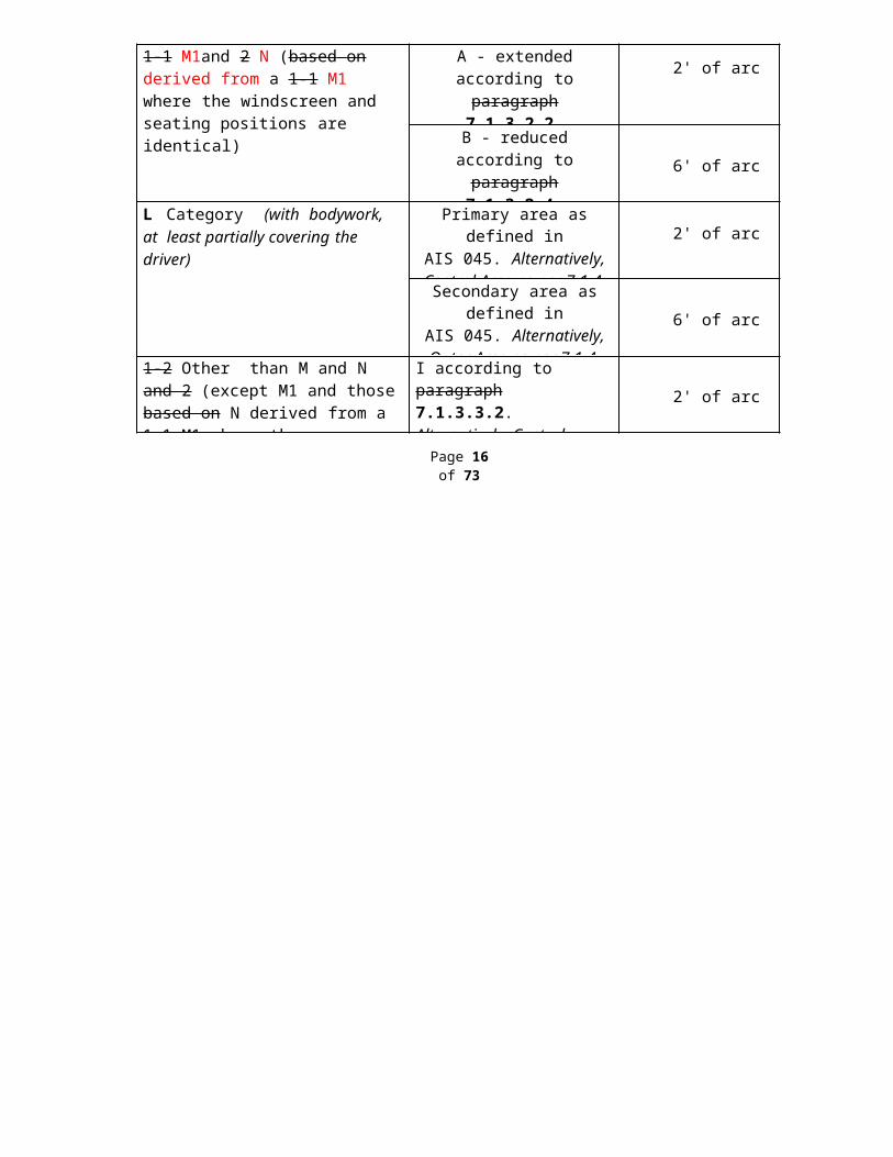
When tested in accordance with 6.12 optical distortion shall not exceed the values given below for each zone or test area.
Vehicle Category Zone or Test Area Maximum values ofOptical Distortion
1-1 M1and 2 N (based on derived from a 1-1 M1 where the windscreen and seating positions are identical)
A - extended according to p ar agraph 7.1.3.2.2.
Alternatively, Central Area as per 7.1.4.
2' of arc
B - reduced according to p ar agraph 7.1.3.2.4.
Alternatively, Outer Area as per 7.1.4.
6' of arc
L Category (with bodywork, at least partially covering the driver)
Primary area as defined inAIS 045. Alternatively,
Central Area as per 7.1.4.2' of arc
Secondary area as defined inAIS 045. Alternatively,
Outer Area as per 7.1.4. 6' of arc
1-2 Other than M and N and 2 (except M1 and those b ased on N derived from a 1-1 M1 where the windscreen and seating position are identical)
I according to paragraph7.1.3.3.2.Alternatively, Central Area as per 7.1.4.
2' of arc
Page 16 of 73
Draft AIS-118/D4June 2012
5.4.1.1 No measurements shall be made in a peripheral area 25 mm inboard of the design glass outline and of any opaque obscuration, provided that it does not impinge into the extended zone A or zone I.
5.4.1.2 In the case of split windscreens, no measurements shall be made in a strip 35 mm from the edge of the windscreen which is adjacent to the dividing pillar.
5.4.1.3 A maximum value of 6' of arc is permitted for all portions of Zone I or Zone A in a peripheral area 100 mm inboard of the design glass outline.
5.4.1.4 Test Pieces
5.4.1.4.1 Four windscreens shall be tested and each shall meet the requirements.
5.4.1.5 Alternate Test Method
Alternate Test Procedure of Optical Distortion Test as per Clause No.5.5.3 of IS: 2553(P2)-1992 shall be also accepted.
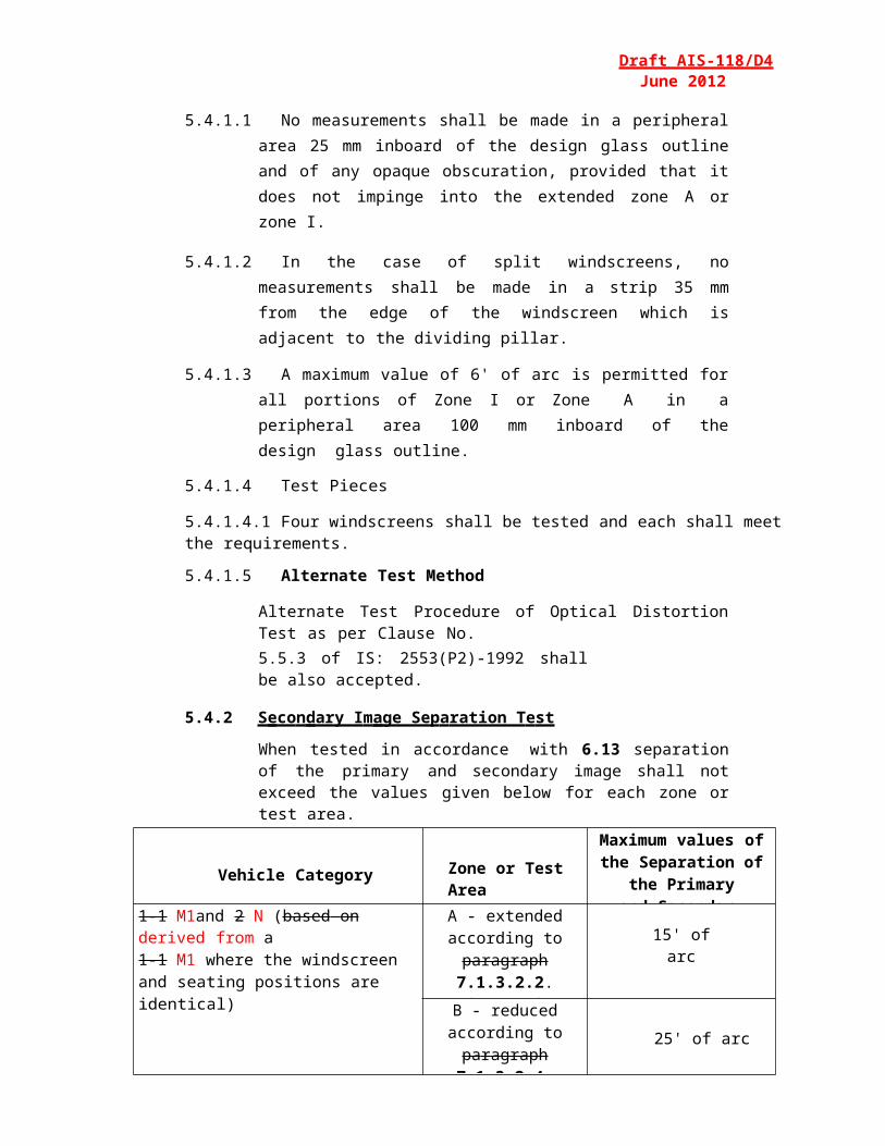
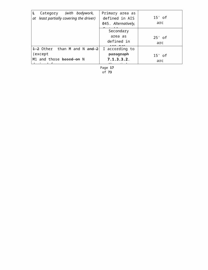
5.4.2 S e co n dary I m age Sep a ration T e st
When tested in accordance with 6.13 separation of the primary and secondary image shall not exceed the values given below for each zone or test area.
Vehicle Category Zone or Test Area
Maximum values of the Separation of the
Primaryand Secondary images
1-1 M1and 2 N (based on derived from a1-1 M1 where the windscreen and seating positions are identical)
A - extended according to
paragraph 7.1.3.2.2. Alternatively, Central
Area as per 7.1.4.
15' of arc
B - reduced according to par agraph 7.1.3.2.4.
Alternatively, Outer Area as per 7.1.4.
25' of arc
L Category (with bodywork, at least partially covering the driver)
Primary area as defined in AIS 045.
Alternatively, Central Area as per 7.1.4.
15' of arc
Secondary area as defined in AIS 045. Alternatively, Outer Area as per 7.1.4.
25' of arc
1-2 Other than M and N and 2 (exceptM1 and those b ased on N derived from a1-1 M1 where the windscreen and seating position are identical)
I according to paragraph 7.1.3.3.2.
Alternatively, Central Area as per 7.1.4.
15' of arc
Page 17 of 73

−5
−0
Draft AIS-118/D4June 2012
5.4.2.1 No measurements shall be made in a peripheral area 25 mm inboard of the design glass outline and of any opaque obscuration, provided that it does not impinge into the extended zone A or zone I.
5.4.2.2 In the case of split windscreens, no measurements shall be made in a strip 35 mm from the edge of the glass pane which is to be adjacent to the dividing pillar.
5.4.2.3 A maximum value of 25' of arc is permitted for all portions of Zone I or Zone A in a peripheral area 100 mm inboard of the design glass outline.
5.4.2.4 Test pieces
5.4.2.4.1 Four windscreens shall be tested and each shall meet the requirements.
5.4.2.5 Alternate Test MethodAlternate test procedure of Secondary Image Separation Test as perClause No. 5.5.2 of IS: 2553(P2)-1992 shall be also accepted.
5.4.3 Head-form Test1 on Windscreens
When tested in accordance with 6.5, at the drop height of 1.5 m +0 mm
(for tests on actual windscreen as per 6.5.3) or 4.0 m +25 mm (for tests
on flat test pieces2 as per 6.5.2), the windscreen shall meet the following requirements:
5.4.3.1 The windscreen shall break displaying numerous circular cracks centred approximately on the point of impact, the cracks nearest to the point of impact being not more than 80 mm from it.
5.4.3.2 The layers of glass shall remain adhering to the interlayer. One or more partial separations from the interlayer with a distance of less than4 mm in breadth, on either side of the crack, are allowed outside a circle of 60 mm diameter centred on the point of impact.
5.4.3.3 On the Impact Side:
5.4.3.3.1 The interlayer shall not be laid bare over an area of more than 20 cm2.
5.4.3.3.2 A tear in the interlayer up to a length of 35 mm is allowed.
‘1’ – this test is not applicable for vehicle of ‘L’ category.‘2’ – Test conducted as per 6.5.2 shall also be acceptable for the compliance to 5.4.3.
Page 18 of 73
−0
Draft AIS-118/D4June 2012
5.4.3.4 Test Pieces
5.4.3.4.1 Eight windscreens shall be tested and at least Seven shall meet the requirements. Or;
5.4.3.4.2 Eight flat test pieces specified at 6.5.5.1 shall be tested and at leastSeven shall meet the requirements.
5.4.4 2,26 0 g Ball Test
When tested in accordance with 6.4., at the drop height of 4 m +25 mm,the ball shall not pass through the glazing within five seconds after the moment of impact.
5.4.4.1 Test Pieces
5.4.4.1.1 Twelve test pieces shall be tested and at least Eleven shall meet the requirements.
5.4.4.1.2 The test pieces shall be as described in 6.4.4.
5.4.5 227 g Ball Test
When tested in accordance with 6.3, at the temperature and drop height specified in 6.3.3.4, the test piece shall meet the following requirements:
5.4.5.1 The ball does not pass through the test piece.
5.4.5.2 The test piece does not break into separate pieces.
5.4.5.3 Tears in the interlayer are allowed provided that the ball does not pass through the test piece.
5.4.5.4 If the interlayer is not torn, the mass of fragments detached from the side of the glass opposite to the point of impact shall not exceed the applicable values specified in 6.3.3.4.
5.4.5.5 Test Pieces
5.4.5.5.1 Ten test pieces shall be tested at each of the specified temperatures and at least Eight of each ten shall meet the requirements.
5.4.5.5.2 The test pieces shall be as described in 6.3.4.
Page 19 of 73

Draft AIS-118/D4June 2012
5.5 Requ ire men ts app lic able to P anes
5.5.1 Requ ire men ts app licable only to Unifor mly Toughen ed Glass Panes
5.5.1.1 Fragmentation Test
When tested in accordance with 6.2, at the points specified in 6.2.2.2, uniformly toughened glass shall fragment as follows:
5.5.1.1.1 The number of fragments in any 5 cm x 5 cm square shall not be less than 40.
5.5.1.1.2 For the purposes of this requirement, a fragment extending across at least one side of a square shall count as half a fragment.
5.5.1.1.3 When a fragment extends beyond the excluded area only the part of the fragment falling outside of the area shall be assessed.
5.5.1.1.4 Fragments of an area exceeding 3 cm2 shall not be allowed except in the parts defined in 6.2.2.3.
5.5.1.1.5 No fragment longer than 100 mm in length shall be allowed except in the areas defined in 6.2.2.3. provided that:
5.5.1.1.5.1 Fragment ends do not converge to a point.
5.5.1.1.5.2 If they extend to the edge of the pane they do not form an angle of more than 45° to it.
5.5.1.1.6 Test Pieces
5.5.1.1.6.1 Four panes shall be tested from each point of impact and at least Three shall meet the requirements.
5.5.1.2 227 g Ball Test
When tested in accordance with 6.3., at the drop height specified in6.3.3.2, the test piece shall not break.
5.5.1.2.1 Test Pieces
5.5.1.2.1.1 Six test pieces shall be tested and at least Five shall meet the requirements.
5.5.1.2.1.2 The test pieces shall be as described in 6.3.4.
Page 20 of 73

−5
Draft AIS-118/D4June 2012
5.5.2 Req u ir e m e n ts ap p li c able only to L a m in a ted- G la s s and Gl a s s- P l as ti c P an es
5.5.2.1 227 g Ball Test
When tested in accordance with 6.3., at the drop height specified in6.3.3.3, the test piece shall meet the following requirements:
5.5.2.1.1 The ball shall not pass through the test piece.
5.5.2.1.2 The laminate shall not break into separate pieces.
5.5.2.1.3 At the point immediately opposite the point if impact, small fragments of glass may leave the specimen, but the small area thus affected shall expose less than 645 mm² of reinforcing or strengthening material, the surface of which shall always be well covered with tiny particles of tightly adhering glass. Total separation of glass from the reinforcing or strengthening material shall not exceed 1935 mm² on either side. Spalling of the outer glass surface opposite the point of impact and adjacent to the area of impact is not to be considered a failure.
5.5.2.1.4 Test Pieces
5.5.2.1.4.1 Eight test pieces shall be tested and at least Six shall meet the requirements.
5.5.2.1.4.2 The test pieces shall be as described in 6.3.4.
5.5.3 Requ ire men ts app lic able only to Doub le-G lazed Units
5.5.3.1 Individual components
Each component pane forming the double-glazed unit shall be separately subjected to the requirements set out in 6. as appropriate for that type of glazing.
5.5.3.2 Head-form Test
When tested in accordance with 6.5 at a drop height of1.50 m +0 mm,the test pieces shall meet following requirements:
5.5.3.2.1 A double-glazed unit consisting of two uniformly toughened-glass panes shall break.
Page 21 of 73
Draft AIS-118/D4June 2012
5.5.3.2.2 A double-glazed unit consisting of laminated-glass panes and/or glass- plastics panes shall meet the following requirements:
5.5.3.2.2.1 The two components of the test piece yield and break, displaying numerous circular cracks centred approximately on the point of impact;
5.5.3.2.2.2 Tears in the interlayer(s) are allowed provided that the head-form does not pass through the test piece;
5.5.3.2.2.3 No fragment larger than 10 cm2 becomes detached from the interlayer.
5.5.3.2.3 A double-glazed unit consisting of a uniformly toughened-glass pane and of a laminated-glass pane or glass-plastics pane shall meet the following requirements:
5.5.3.2.3.1 The uniformly toughened glass pane breaks;
5.5.3.2.3.2 The laminated-glass pane or glass-plastics pane:
5.5.3.2.3.2.1 Yields and breaks, displaying numerous circular cracks centred approximately on the point of impact;
5.5.3.2.3.2.2 Tears in the interlayer(s) are allowed provided that the head-form does not pass through the test piece;
5.5.3.2.3.2.3 No fragment larger than 10 cm2 becomes detached from the interlayer.
5.5.3.2.4 Test Pieces
5.5.3.2.4.1 Twelve test pieces shall be tested and at least Eleven shall meet the requirements.
5.5.3.2.4.2 The test pieces shall be as described in 6.5.5.1.
5.5.3.2.4.3 In the case of an asymmetrical double-glazed unit, six tests shall be carried out on one side and six tests on the other side.
Page 22 of 73
Draft AIS-118/D4June 2012
5.6 Requirements Specific to Rigid Plastic Glazing
5.6.1 Headform Test:
5.6.1.1 The method used shall be that described in 6.16
5.6.1.2 Six flat test pieces (1170 x 570 +0/-2 mm) or six complete parts shall be subjected to testing.
5.6.1.3 For Panes like Partitions and separating windows which have impact probability (Classification VII/A) the drop height shall be 3m. The HIC Value has to be measured.
5.6.1.4 For Panes like Side Windows and back windows which have reduced impact possibilities (Classification VII/B) the drop height shall be 1.5m. The HIC Value is also to be measured.
5.6.1.5 For Panes which do not have contact possibilities as well as for small windows in vehicles and for all windows in trailers (Classification VII/C) there will be no headform testing. A small window is a window into which a 150mm diameter circle cannot be scribed.
5.6.1.6 The test shall be deemed to have given a satisfactory result if the following conditions are fulfilled.
5.6.1.7 The test piece or sample is not penetrated nor shall it break into fully separate large pieces.
5.6.1.8 The HIC Value is less than 1000.
5.6.2 Mechanical Strength Test - 227g Ball
5.6.2.1 The method used shall be that described in 6.3
5.6.2.2 Ten Flat Square pieces (300 +10/-0 mm) or ten substantially flat finished parts shall be subjected to testing.
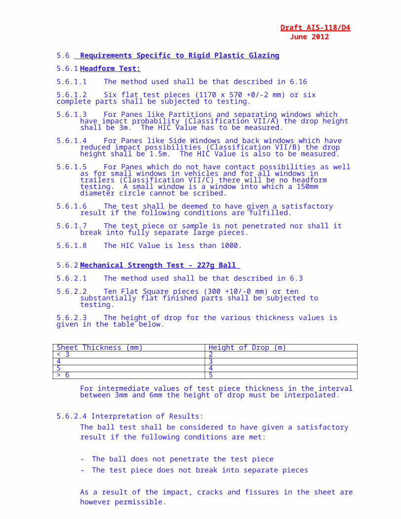
5.6.2.3 The height of drop for the various thickness values is given in the table below.
Sheet Thickness (mm) Height of Drop (m)< 3 24 35 4> 6 5
For intermediate values of test piece thickness in the interval between 3mm and 6mm the height of drop must be interpolated.
5.6.2.4 Interpretation of Results:The ball test shall be considered to have given a satisfactory result if the following conditions are met:
- The ball does not penetrate the test piece- The test piece does not break into separate pieces
As a result of the impact, cracks and fissures in the sheet are however permissible.
5.6.2.5 227g ball test at -18° ± 2°C
5.6.2.5.1To minimize the temperature change of the test piece, the test shall be performed within 30 seconds of the removal of the test piece from the conditioning appliance.
5.6.2.5.2 The test method shall be as per 6.3, except that the test temperature is -18° ± 2°C.
5.6.2.5.3 Interpretation of results to be as per 5.6.2.4
5.6.3 Flexibility & Fold Test
5.6.3.1 One flat test piece measuring 300mm x 25mm shall be subjected to testing.
5.6.3.2 The method used shall be that mentioned in 6.17
5.6.3.3 Interpretation of results:For a test piece or sample to be considered rigid, the vertical deflection of the test piece shall be less than or equal to 50mm after 60 seconds.
5.6.4 Weathering
5.6.4.1 The test method shall be that mentioned in 6.18. The total Ultraviolet radiant exposure with the long arc xenon lamp shall be 500 MJ/m2. . During irradiation, the test pieces shall be exposed to water spray in continuous cycles. During a cycle of 120 minutes, the test pieces are exposed to light without water spray for 102 minutes, and to light with water spray for 18 minutes.
5.6.4.2 Other methods giving equivalent results shall be allowed.
5.6.4.3 Number of test piecesThree flat pieces 130 x 40mm cut from a flat sheet sample shall be subjected to testing.
5.6.4.4 Interpretation of Results:
5.6.4.4.1 The resistance to the simulated weathering shall be considered to have given a satisfactory result if:
5.6.4.4.2 The light transmittance measured in accordance with 6.1 does not fall below 95% of the pre-weathering value. Additionally, for windows which are required for driver visibility, the value shall not fall below 70%.
5.6.4.4.3 No bubbles or other visible decompositions, discolourations, milkiness or crazing shall occur during weathering.
5.6.4.4.4 A set of test pieces or samples submitted for approval shall be considered satisfactory from the point of view of the resistance to simulated weathering if one of the following conditions is met:
5.6.4.4.5 All test pieces have given a satisfactory result
5.6.4.4.6 One test piece having given an unsatisfactory result, a further series of tests carried out on a new set of test pieces or samples gives satisfactory results.

5.6.5 Cross-cut
5.6.5.1 The method used shall be that mentioned in 6.19
5.6.5.2 The cross-cut test shall be carried out on one of the test pieces from 5.6.4
5.6.5.3 Interpretation of Results
5.6.5.3.1 The cross-cut test shall be considered to have given a satisfactory result if:
5.6.5.3.2 The cross-cut value Gt1 is met.
5.6.5.3.3 The test piece shall be considered satisfactory from the point of view of approval if one of the following conditions is met.
5.6.5.3.4 The test has given satisfactory results
5.6.5.3.5 The test having given an unsatisfactory result, a further test carried out on another remaining test piece from test 5.6.4 gives satisfactory results.
5.7 Requirements Specific to Flexible Plastic Glazing
5.7.1 227 g ball Test at 20 ± 5°C
5.7.1.1 Ten flat square pieces (300 +10/-0 mm) shall be subjected to testing.
5.7.1.2 The test method used shall be that prescribed in 6.3
5.7.1.3 The height of drop is 2m for all thicknesses.
5.7.1.4 Interpretation of Results:The ball test shall be considered to have given a satisfactory result if the ball does not penetrate the test piece
5.7.1.5 227g ball test at -18° ± 2°C
5.7.1.5.1 To minimize the temperature change of the test piece, the test shall be performed within 30 seconds of the removal of the test piece from the conditioning appliance.
5.7.1.5.2 The test method shall be as per 6.3, except that the test temperature is -18° ± 2°C.
5.7.1.5.3 Interpretation of results to be as per 5.7.1.4
5.7.2 Flexibility test and Fold Test
5.7.2.1 One flat test piece measuring 300mm x 25mm shall be subjected to testing.
5.7.2.2 The method used shall be that mentioned in 6.17.
5.7.2.3 Interpretation of results:For a test piece or sample to be considered flexible, the vertical deflection of the test piece shall be more than 50mm after 60 seconds.
10 seconds after a 180° folding, the material must not show any fracture or damage at the point of bending,
6 TEST CONDITIONS AND PROCEDURES
6.1 Test Conditio ns
Unless specified otherwise, the test conditions shall be as follows:
6.1.1 Temperature: 20 ± 5°C.
6.1.2 Pressure: 860 to 1060 mbar.
6.1.3 Relative humidity: 60 ± 20%
6.2 Fragmentation Test
6.2.1 Apparatus
6.2.1.1 To obtain fragmentation, a spring-loaded centre punch or a hammer of75 g ± 5g, each with a point having a radius of curvature of0.2 ± 0.05 mm, shall be used.
6.2.2 Procedure
6.2.2.1 The test piece to be tested shall not be rigidly secured; it may however be fastened on an identical test piece by means of adhesive tape applied all round the edge.
6.2.2.2 One test shall be carried out at each of the prescribed point of impact.
6.2.2.3 Fragmentation shall not be checked in a strip 2 cm wide round the edge of the samples, this strip representing the frame of the glass, nor within a radius of 7.5 cm from the point of impact.
6.2.2.4 Examination of the fragmentation pattern shall start within 10 seconds and shall be completed within 3 minutes after the impact.
6.2.3 Points of impact for uniformly toughened glass panes
They are as follows, and represented in 7.2, Figures 2(a), 2(b) and 2(c).
6.2.3.1 Point 1: in the Geometric Centre of the Glass.
6.2.3.2 Point 2: for curved glass panes only; this point shall be selected on the largest median in that part of the pane where the radius of curvature "r" of the glazing is less than 200 mm.
Page 23 of 73
Draft AIS-118/D4June 2012
6.2.3.3 Test Pieces
6.2.3.3.1 E ight p an es Four panes for each point of impact.
This is in line with Informal document GRSG-97-1.
6.3 227 g Ball Test
6.3.1 Apparatus
6.3.1.1 Solid, smooth, hardened-steel ball with a mass of 227 g ± 2 g and a diameter of approximately 38mm.
6.3.1.2 Means for dropping the ball freely from the height in 6.3.3., or a means for giving the ball a velocity equivalent to that obtained by the free fall. When a device to project the ball is used, the tolerance on velocity shall be ± 1 per cent of the velocity equivalent to that obtained by the free fall.
6.3.1.3 Supporting fixture, such as that shown in Figure 1, composed of steel frames, with machined borders 15 mm wide, fitting one over the other and faced with rubber gaskets 3 mm thick and 15 mm wide and of hardness 50 ± 10 International Rubber Hardness Degree (IRHD).
The lower frame rests on a steel box 150 mm high. The test piece is held in place by the upper frame, the mass of which is 3 kg. The supporting frame is welded onto a sheet of steel 12 mm thick resting on the floor with an interposed sheet of rubber 3 mm thick and of hardness 50 ± 10 IRHD.
Figure 1: Suppo rt fo r Ball T ests
Page 24 of 73
− 0
− 0
Draft AIS-118/D4June 2012
6.3.2 Procedure
6.3.2.1 Condition the test piece at the temperature specified in 6.1.1 for at least four hours immediately preceding the test. In the case of laminated- glass and glass plastic windscreens the temperatures will be as specified in 6.3.3.4.
6.3.2.2 Place the test piece in the fixture described in 6.3 .2.3 6.3.1.3. The plane of the test piece shall be perpendicular, within 3°, to the incident direction of the ball. In the case of flexible plastic glazing, the test piece shall be clamped to the support.
6.3.2.3 The point of impact shall be within 25 mm of the centre of the supported area for a drop height less than or equal to 6 m, and within50 mm of the centre of the supported area for a drop height greater than 6 m.
6.3.2.4 The ball shall strike the outer face of the test piece.
(Note: Glass / Plastic Glazing M a n u f a c t u r e r t o prov ide mark ing o f inner & outer surface on cut pieces.)
6.3.2.5 The ball shall make only one impact.
6.3.3 Drop Height
6.3.3.1 The drop height shall be measured from the under-face of the ball to the upper face of the test piece.
6.3.3.2 For Uniformly Toughened Glass Panes, the drop height shall be2.0 m +5 mm.
6.3.3.3 For Laminated-Glass and Glass-Plastic Panes, the drop height shall be
9 m + 25− 0 mm.
6.3.3.4 For laminated-glass and glass-plastic windscreens, the drop height and the mass of the detached fragments shall be as indicated in the following table, where e equals the nominal thickness of the specimen being tested. A tolerance of + 25 mm is allowed in the height of fall.
6.3.3.5 For Plastic Glazing, the height of drop for the various thickness values of the outer compartment of the window is given in the table below.
Page 25 of 73
Draft AIS-118/D4June 2012
Outer Sheet Thickness (mm) Height of Drop (m)< 3 24 35 4
> 6 5
For intermediate values of test-piece thickness in the interval between 3mm and 6mm the height of drop must be interpolated.
For all Glazing excluding Plastic glazing, ten test pieces shall be tested at a temperature of +40 ± 2°C and ten at a temperature of -20 ± 2°C.
NominalThickness
of Test Pieces
(mm)
+40 ± 2°C -20 ± 2°CHeight of
Fall
(m)
Maximum permitted
mass of the fragments
(g)
Height ofFall
(m)
Maximum permitted
mass of the fragments
(g)e ≤ 4.5
4.5 < e ≤ 5.55.5 < e ≤ 6.5
e > 6.5
9999
12152025
8.58.58.58.5
12152025
For Plastic Glazing, the 227g ball test at -18 ± 2°C is to be done using the procedure described above.
6.3.4 Test Pieces
6.3.4.1 The test pieces shall be flat samples measuring 300 mm x 300 mm, specially made or cut from the flattest part of a windscreen or pane.
6.3.4.2 Test pieces can alternatively be finished products Finished Products may alternatively be used as test pieces which tha t ma y shall be supported over the apparatus described in 6.3.1.
6.3.4.3 If the test pieces are curved, care should be taken to ensure adequate contact with the support.
6.4 2,2 6 0 g Ball T e st
6.4.1 Apparatus
6.4.1.1 Solid hardened-steel ball with a mass of 2,260 g ± 20 g.
6.4.1.2 Means for dropping the ball freely from the height specified in 6.4.2.7.
or means for giving the ball a velocity equivalent to that obtained by the free fall.When a device to project the ball is used, the tolerance on velocity shall be ± 1 per cent of the velocity equivalent to that obtained by the free fall.
6.4.1.3 The supporting fixture shall be as shown in Figure 1 and identical with that described in 6.3.1.3.
Page 26 of 73
− 0
Draft AIS-118/D4June 2012
6.4.2 Procedure
6.4.2.1 Condition the test piece at the temperature specified in 6.1.1 for at least four hours immediately preceding the test.
6.4.2.2 Place the test piece in the supporting fixture. The plane of the test piece shall be perpendicular within 3°, to the incident direction of the ball.
6.4.2.3 In the case of glass-plastics glazing the test piece shall be clamped to the support. All other glazing shall not be clamped.
6.4.2.4 The point of impact shall be within 25 mm of the geometric centre of the test piece.
6.4.2.5 The ball shall strike the inner face of the test piece.
6.4.2.6 The ball shall make only one impact.
6.4.3 Drop Height
6.4.3.1 The drop height shall be measured from the under face of the ball to the upper face of the test piece.
6.4.3.2 The drop height shall be 4.0 m +5 mm.
6.4.4 Test Pieces
6.4.4.1 The test pieces shall be flat samples measuring 300 mm x 300 mm, specially made or cut from the flattest part of a windscreen.
6.4.4.2 Finished products may alternatively be used as test pieces which shall be supported over the apparatus described in 6.3.1.
6.4.4.3 If the test pieces are curved, care should be taken to ensure adequate contact with the support.
Page 27 of 73
Draft AIS-118/D4June 2012
6.5 Head-fo r m T e st
6.5.1 Apparatus
6.5.1.1 Head-form
6.5.1.1.1 Spherical or semi-spherical head-form made of laminated hardwood covered with replaceable felt and with or without a crossbeam made of wood. There is a neck shaped intermediate piece between the spherical part and the crossbeam and a mounting rod on the other side of the crossbeam.
F igure 2: He ad-f or m
6.5.1.1.2 The dimensions shall be in accordance with Figure 2.
6.5.1.1.3 The total mass of the head-form shall be 10 ± 0.2 kg.
6.5.1.2 Means for dropping the head-form freely from a height to be specified, or means for giving the head-form a velocity equivalent to that obtained by the free fall. When a device to project the head-form is used, the tolerance on velocity shall be ± 1% of the velocity equivalent to that obtained by the free fall.
6.5.1.3 Supporting fixture, as shown in Figure 3, for testing Flat Test Pieces.The fixture is composed of two steel frames, with machined borders50 mm wide, fitting one over the other and faced with rubber gaskets 3 mm thick and 15 ± 1 mm wide and of hardness 70 ± 10 IRHD.
Page 28 of 73
Draft AIS-118/D4June 2012
The upper frame is held pressed against the lower frame by at least eight bolts. The torque on the bolts shall ensure that the movement of the test piece during the test will not exceed 2 mm.
Figure 3: Head-for m test support for F lat Sa mp les
6.5.1.4 Supporting fixture for Windscreens:
The support shall consist of a rigid piece corresponding to the shape of the windscreen so that the head-form strikes the inner face of the windscreen. It has an interposed strip of rubber of hardness 70 ± 10IRHD, thickness 3 mm and width 15 mm. The support shall rest on a rigid stand with an interposed sheet of rubber of hardness 70 ± 10IRHD and thickness 3 mm.
1 / The minimum recommended torque for M20 is 30 N-m.
6.5.2 Procedure for Tests on Flat Test Pieces.
6.5.2.1 Condition the test piece at the temperature specified in 6.1.1 for at least four hours immediately preceding the test.
Page 29 of 73
−5
−2
Draft AIS-118/D4June 2012
6.5.2.2 Fix the test piece in the supporting frame described in 6.5.1.3.
6.5.2.3 The plane of the test piece shall be perpendicular within 3°, to the incident direction of the head-form.
6.5.2.4 The head-form shall strike the test piece within 40 mm of its geometric centre on its inner face.
6.5.2.5 The head-form shall make only one impact.
6.5.2.6 The impact surface of the felt cover shall be replaced after each successive 12 tests.
6.5.3 Procedure for Tests on Windscreens
6.5.3.1 Condition the test piece at the temperature specified in 6.1.1 for at least four hours immediately preceding the test.
6.5.3.2 Place the windscreen freely on a supporting fixture as described in6.5.1.4.
6.5.3.3 The plane of the windscreen shall be perpendicular within 3°, to the incident direction of the head-form.
6.5.3.4 The head-form shall strike the windscreen within 40 mm of its geometric centre on its inner face.
6.5.3.5 The head-form shall make only one impact.
6.5.3.6 The impact surface of the felt cover shall be replaced after each successive 12 tests.
6.5.4 Drop Height
6.5.4.1 The drop height shall be measured from the under-face of the head- form to the upper face of the test piece.
6.5.4.2 It shall be 1.5 m +0 mm for tests conducted on Windscreens and onflat samples for double glazed units.
6.5.5 Test Pieces
6.5.5.1 The test pieces according to 6.5.2 shall be flat samples measuring
1,100 mm x 500 mm +10 mm.
6.5.5.2 The test pieces according to 6.5.3 shall be windscreens.
Page 30 of 73
6.6 Test of R esistan ce to Abrasion
Draft AIS-118/D4June 2012
6.6.1 Apparatus
6.6.1.1 Abrading instrument as shown in Figure 4 2/ and consisting of:
6.6.1.1.1 A horizontal turntable, with centre clamp, which revolves counter- clockwise at 65 to 75 rev/min.
6.6.1.1.2 Two weighted parallel arms each carrying a special abrasive wheel freely rotating on a ball-bearing horizontal spindle; each wheel rests on the test specimen under the pressure exerted by a mass of 500 g.
6.6.1.1.3 The turntable of the abrading instrument shall rotate regularly; substantially in one plane (the deviation from this plane shall not be greater than ± 0.05 mm at a distance of 1.6 mm from the turntable periphery).
6.6.1.1.4 The wheels shall be mounted in such a way that when they are in contact with the rotating test piece they rotate in opposite directions so as to exert, twice during each rotation of the test piece, a compressive and abrasive action along curved lines over an annular area of about 30 cm2.
Figure 4: Di a g ram of A brading Inst ru m e n t
6.6.1.2 Abrasive wheels 3 /, each 45 to 50 mm in diameter and 12.5 mm thick, composed of a special finely-screened abrasive embedded in amedium hard rubber.
2 / An example of a suitable abrading instrument is that supplied by Teledyne Taber(United States of America).3 / An example of suitable abrasive wheels are is those that can may be obtained fromTeledyne Taber (United States of America).
Page 31 of 73
Draft AIS-118/D4June 2012
6.6.1.2.1 The wheels shall have a hardness of 72 ± 5 IRHD, as measured at four points equally spaced on the centerline of the abrading surface, the pressure being applied vertically along a diameter of the wheel and the readings being taken 10 seconds after full application of the pressure.
6.6.1.2.2 The abrasive wheels shall be prepared for use by very slow rotation against a sheet of flat glass to ensure that their surface is completely even.
6.6.1.3 Light source consisting of an incandescent lamp with its filament contained within a parallelepiped measuring 1.5 mm x 1.5 mm x 3 mm. The voltage at the lamp filament shall be such that the color temperature is 2,856 ± 50 K. This voltage shall be stabilized within± 1/1000.
6.6.1.4 Optical system consisting of a lens with a focal length (f) of at least500 mm and corrected for chromatic aberrations.
6.6.1.4.1 The full aperture of the lens shall not exceed f/20.
6.6.1.4.2 The distance between the lens and the light source shall be adjusted in order to obtain a light beam which is substantially parallel.
6.6.1.4.3 A diaphragm shall be inserted to limit the diameter of the light beam to 7 ± 1 mm. This diaphragm shall be situated at a distance of100 ± 50 mm from the lens on the side remote from the light source.
6.6.1.5 Equipment for measuring scattered light (Figure 5), consisting of a photoelectric cell with an integrating sphere 200 to 250 mm in diameter. The sphere shall be equipped with entrance and exit ports for the light. The entrance port shall be circular and have a diameter at least twice that of the light beam. The exit port of the sphere shall be provided with either a light trap or a reflectance standard, according to the procedure described in 6.6.2.6. The light trap shall absorb all the light when no test piece is inserted in the light beam.
6.6.1.5.1 The axis of the light beam shall pass through the centre of the entrance and exit ports. The diameter b of the light-exit port shall be equal to 2a tan 4°, where a is the diameter of the sphere. The photoelectric cell shall be mounted in such a way that it cannot b e reach ed by the light coming directly from the entrance port or fromthe reflectance standard does not reach the cell.
Page 32 of 73
Draft AIS-118/D4June 2012
6.6.1.5.2 The surfaces of the interior of the integrating sphere and the reflectance standard shall be of substantially equal reflectance and shall be matte and non-selective.
6.6.1.5.3 The output of the photoelectric cell shall be linear within ± 2 per cent over the range of luminous intensities used. The design of the instrument shall be such that there is no galvanometer deflection when the sphere is dark.
6.6.1.5.4 The whole apparatus shall be checked at regular intervals by means of calibration standards of defined haze.
F igure 5: Ha z e m e ter
6.6.2 Procedure
6.6.2.1 The abrasion test shall be carried out on that surface of the test piece which represents the outer side of the glass pane and also on the inner side if of plastics material.
6.6.2.2 Immediately before and after the abrasion, clean the test pieces in the following manner:(a). Wipe with a linen cloth under clean running water; (b). Rinse with distilled or demineralised water;(c). Blow dry with oxygen or nitrogen;(d). Remove possible traces of water by dabbing softly with a damp
linen cloth. If necessary, dry by pressing lightly between two linen cloths.
Any treatment with ultrasonic equipment is prohibited.
Page 33 of 73
d
Draft AIS-118/D4June 2012
6.6.2.3 After cleaning, the test pieces shall be handled only by their edges and shall be stored to prevent damage to, or contamination of, their surfaces.
6.6.2.4 Recondition the test pieces as specified in 6.1 for a minimum time of48 hours.
6.6.2.5 Immediately place the test piece against the entrance port of the integrating sphere. The angle between the normal (perpendicular) to the surface of the test piece and the axis of the light beam shall not exceed 8°.
6.6.2.6 Take Four readings as indicated in the following Table:
Reading With TestPiece
With LightTrap
With Reflectance Standard
Quantity Represented
T1 No No Yes Incident light
T2 Yes No Yes Total Light Transmitted byTest Piece
T3 No Yes No Light Scattered byInstrument
T4 Yes Yes No Light Scattered byInstrument and Test Piece
6.6.2.7 Repeat readings for T1, T2, T3 and T4 with other specified positions of the test piece to determine uniformity.
6.6.2.8 Calculate the Total Transmittance .
6.6.2.9 Calculate the Diffuse Transmittance Td as follows:
T = T4 − T3 (T2 / T1
)T1 − T3
6.6.2.10 Calculate the Percentage Haze, or Light, or Both, Scattered, as follows:
6.6.2.11 Haze, or light or both, Scattered, = x 100%
6.6.2.12 Measure the initial haze of the test piece at a minimum of four equally spaced points in the unabraded area in accordance with the formula above. Average the results for each test piece. In lieu of the four measurements, an average value may be obtained by rotating the pieceuniformly at 3 rev/sec or more.
Page 34 of 73
Draft AIS-118/D4June 2012
6.6.2.13 For each type of safety glazing, carry out three tests with the same load. Use the haze as a measure of the subsurface abrasion, after the test piece has been subjected to the abrasion test.
6.6.2.14 Measure the light scattered by the abraded track at a minimum of four equally spaced points along the track in accordance with the formula above. Average the results for each test piece. In lieu of the four measurements, an average value may be obtained by rotating the piece uniformly at 3 rev/sec or more.
6.6.3 Test Pieces
6.6.3.1 The test pieces shall be flat samples (Square) measuring 100 mm x 100 mm having both surfaces substantially plane and parallel and having a fixing hole 6 +0.2 / -0 mm in diameter drilled in the center, if necessary – Text available in ECE R43).
6.7 Te s t of Res is tance to High Tempe r ature
6.7.1 Procedure
6.7.1.1 Heat to 100 °C.
6.7.1.2 Maintain this temperature for a period of two hours, and then allow the test pieces to cool to the temperature at 20°±5°C.
6.7.1.3 If the test piece has both external surfaces of inorganic material, the test may be carried out by immersing the test piece vertically in boiling water for the specified period of time, care being taken to avoid undue thermal shock.
6.7.2 Test Pieces
6.7.2.1 The test pieces shall be flat samples measuring 300 mm x 300 mm, which have been specially made or cut from the flattest part of three windscreens or three panes, as the case may be, one edge of whichcorresponds to the upper edge of the glazing.
6.7.2.2 Alternate Test MethodAlternate Test Procedure of Boil Test as per Clause No. 5.3.4 ofIS: 2553(P1)- 1990 shall be also accepted.
Page 35 of 73
Draft AIS-118/D4June 2012
6.8 Te s t of Res i s t ance to Ra d i a tion
6.8.1 Apparatus
6.8.1.1 Radiation source consisting of a medium-pressure mercury-vapour arc lamp with a tubular quartz bulb of ozone-free type; the bulb axis shall be vertical. The nominal dimensions of the lamp shall be 360 mm in length by 9.5 mm in diameter. The arc length shall be 300 ± 4 mm. The lamp shall be operated at 750 ± 50 W.
Any other source of radiation which produces the same effect as the lamp specified above may be used. To check that the effects of another source are the same, a comparison shall be made by measuring the amount of energy emitted within a wavelength range of 300 to 450 nanometers, all other wavelengths being removed by the use of suitable filters.
6.8.1.2 Power-supply transformer and capacitor capable of supplying to the lamp specified in 6.8.1.1 a starting peak voltage of 1,100 V minimum and an operating voltage of 500 ± 50 V.
6.8.1.3 Device for mounting and rotating the test pieces at 1 to 5 rev/min about the centrally located radiation source in order to ensure even exposure.
6.8.2 Procedure
6.8.2.1 Check the regular light transmittance, determined according to 6.11, of three test pieces before exposure. Protect a portion of each test piece from the radiation, and then place the test pieces in the test apparatus230 mm from and parallel lengthwise to the lamp axis. Maintain the temperature of the test pieces at 45 ± 5 °C throughout the test.
6.8.2.2 That face of the test piece which would constitute the outer face of the glazing shall face the lamp.
6.8.2.3 The exposure time shall be 100 hours. Each test piece shall be subjected to radiation such that the radiation on each point of the test piece produces on the interlayer the same effect as that which would be produced by solar radiation of 1,400 W/m2 for 100 hours.
6.8.2.4 After exposure, measure the regular light transmittance again in the exposed area of each test piece.
Page 36 of 73
Draft AIS-118/D4June 2012
6.8.3 Test Pieces
6.8.3.1 The test pieces shall be flat samples measuring 76 mm x 300 mm or300 mm x 300 mm, which have been specially made or cut from three windscreens or three panes, as the case may be, one edge of which corresponds to the upper edge of the glazing.
6.9 Te s t of Res i s t ance to Humidity
6.9.1 Procedure
6.9.1.1 Keep samples in a vertical position for two weeks in a closed container in which the temperature is maintained at 50 ± 2 °C and the relative humidity at 95 ± 4%.
6.9.1.2 If several test pieces are tested at the same time, spacing shall be provided between them.
6.9.1.3 Precautions shall be taken to prevent condensate from the walls or ceiling of the test chamber from falling on the test pieces.
6.9.1.4 Before assessment, laminated-glass test pieces shall have been maintained for two hours in the conditions specified in 6.1.
6.9.1.5 Before assessment, test pieces of glass faced with plastic and of glass- plastics shall have been maintained for 48 hours in the conditions specified in 6.1.
6.9.2 Test Pieces
6.9.2.1 The test pieces shall be samples measuring 300 mm x 300 mm, which have been specially made or cut from three windscreens or three panes, as the case may be. One edge at least shall correspond to an edge of theglazing.
Page 37 of 73
Draft AIS-118/D4June 2012
6.10 Te s t of Res i s t ance to T e mperature C h anges
6.10.1 Procedure
6.10.1.1 Test pieces shall be placed in an enclosure at a temperature of-40°C ± 5°C for a period of 6 hours; they shall then be placed in the open air at a temperature of 23°C ± 2°C for one hour or until temperature equilibrium has been reached by the test pieces.
NOTE - Components tested at -20 ± 5 °C shall be acceptable, as an alternate.
6.10.1.2 Test pieces shall then be placed in circulating air at a temperature of+72°C ± 2 °C for 3 hours.
6.10.1.3 After being placed again in the open air at +23°C ± 2 °C and cooled to that temperature, the test pieces shall be examined.
6.10.2 Test Pieces
6.10.2.1 The test pieces shall be flat samples measuring 300 mm x 300 mm, which have been specially made or cut from three windscreens or panes, as the case may be.
6.11 Ligh t Transm ittance T es t
6.11.1 Apparatus
6.11.1.1 Light source consisting of an incandescent lamp with its filament contained within a parallelepiped measuring 1.5 mm x 1.5 mm x3 mm. The voltage at the lamp filament shall be such that the color temperature is 2,856 ± 50 K. This voltage shall be stabilized within± 1/1,000.
6.11.1.2 Optical system consisting of a lens with a focal length (f ) of at least500 mm.
6.11.1.2.1 The full aperture of the lens shall not exceed f/20.
6.11.1.2.2 The distance between the lens and the light source shall be adjusted in order to obtain a light beam which is parallel.
6.11.1.2.3 A diaphragm shall be inserted to limit the diameter of the light beam to7 ± 1 mm. This diaphragm shall be situated at a distance of100 ± 50 mm from the lens on the side remote from the light source. The point of measurement shall be taken at the centre of the light beam.
Page 38 of 73
Draft AIS-118/D4June 2012
6.11.1.3 Measuring Equipment:
6.11.1.3.1 The receiver shall have a relative spectral sensitivity in substantial agreement with the relative spectral luminous efficiency for the ICI 4/ standard photometric observer for photocopy vision. The sensitive surface of the receiver shall be covered with a diffusing medium and shall have at least twice the cross-section of the light beam emitted by the optical system. If an integrating sphere is used, the aperture of the sphere shall have a cross-sectional area at least twice that of the parallel portion of the beam.
6.11.1.3.2 The linearity of the receiver and the associated indicating instrument shall be within 2% of the effective part of the scale.
6.11.1.3.3 The receiver shall be centered on the axis of the light beam.
4 / International Commission on Illumination
6.11.2 Procedure:-
6.11.2.1 The sensitivity of the measuring system shall be adjusted in such a way that the instrument indicating the response of the receiver indicates100 divisions when the safety glazing material is not inserted in the light path. When no light is falling on the receiver, the instrument shall read zero.
6.11.2.2 Place the glazing at a distance from the receiver equal to five times the diameter of the receiver. Insert the glazing between the diaphragm and the receiver and adjust its orientation in such a way that the angle of incidence of the light beam is equal to 0 ± 5°. The regular light transmittance shall be measured on the glazing, and for every point measured the number of divisions, n, shown on the indicating instrument, shall be read. The regular transmittance tr is equal to n/100.
6.11.3 Test Pieces
6.11.3.1 Test pieces shall be either flat samples or finished products.
6.11.3.2 In the case of windscreens the test area shall be as defined in 7.1.3.4.
6.12 Optical Distortion Test
6.12.1 ApparatusThe apparatus shall comprise the following items, arranged as shown in Figure 6
Page 39 of 73
Draft AIS-118/D4June 2012
Figure 6: Arrang e m en t o f t he appa r a tus for the Optical Distortion T e st
6.12.1.1 Projector with a high-intensity point light source.
6.12.1.1.1 The projector shall have the following characteristics:
6.12.1.1.1.1 Focal length at least 90 mm.6.12.1.1.1.2 Aperture 1/2.5
6.12.1.1.1.3 150 W quartz halogen lamp (if used without a filter).
6.12.1.1.1.4 250 W quartz halogen lamp (if a green filter is used).
6.12.1.1.1.4.1 The projector is shown schematically in Figure 7. A diaphragm of 8 mm in diameter is positioned 10 mm from the front lens.
Figur e 7: Optical arrangement o f th e Pro jecto r
6.12.1.2 Slides (rasters) consisting, for example, of an array of bright circular shapes on a dark background (see Figure 8). The slides shall be of sufficiently high quality and contrast to enable measurement to be carried out with an error of less than 5 per cent.
Page 40 of 73
Draft AIS-118/D4June 2012
In the absence of the glazing to be examined, the dimensions of the circular shapes shall be such that when the circular shapes are projected they form an array of circles of diameter:D = where = 4 mm (Figures 6 and 9).
F igure 8: E n lar g ed sec t i o n of the Sli d e
Figure 9: Diagram m atic represe n t a tion of O p t ical D istort i on
Notes: , i.e. the optical distortion in the direction M-M'. = MC, i.e. the distance between two straight lines parallel to the direction
of vision and passing through the points M and M'.
6.12.1.3 Support stand, permitting vertical and horizontal scanning, rotation of the windscreen, and mounting of the windscreen at a full range of installation angles of inclination.
6.12.1.4 Checking template for measuring changes in dimensions. A suitable design is shown in Figure 10.
Page 41 of 73
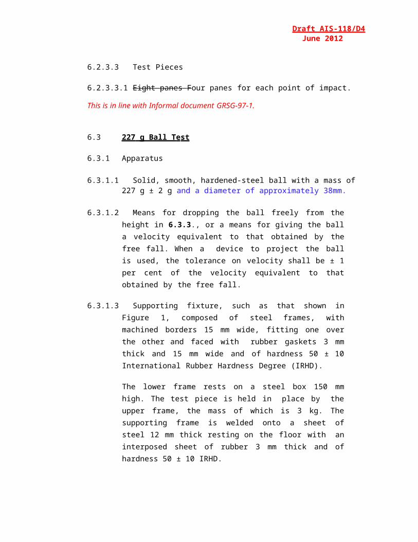
Figure 10: D esig n for a Suitable Checkin g Te mp late
Draft AIS-118/D4June 2012
6.12.2 Procedure
6.12.2.1 General
6.12.2.1.1 Mount the windscreen on the support stand at the designed angle of inclination.
6.12.2.1.2 Project the test image through the area being examined.6.12.2.1.3 Rotate the windscreen or move it either horizontally or vertically in
order to examine the whole of the specified area.
6.12.2.1.4 The distance shall be 4 mm.
6.12.2.1.5 The projection axis in the horizontal plane shall be maintained approximately normal to the trace of the windscreen in that plane.
6.12.2.2 Calculate the value of A (Figure 10) from the limit value for the change in deviation and the value of R2, the distance from the windscreen to the display screen:
The relationship between the change in diameter of the projected image and the change in angular deviation is given by:
∆α = ∆d0.29 × R2
Where:is in mm, A is in mm, is in minutes of arc, is in minutes of arc, R2 is in m.
Page 42 of 73
Draft AIS-118/D4June 2012
6.12.3 Expression of Results: Evaluate the Optical Distortion of the windscreen by measuring at any point of the surface and in all directions in order to find max.
6.12.4 Alternative Method: A strioscopic technique is permitted as an alternative to the projection techniques, provided that the accuracy of the measurements given in 6.12.2.2 is maintained.
6.12.5 Test Pieces
6.12.5.1 The test pieces shall be windscreens.
6.13 Secondary Image Separation test
6.13.1 Target Test
6.13.1.1 Apparatus
6.13.1.1.1 This method involves viewing an illuminated target through the windscreen. The target may be designed in such a way that the test can be carri ed out it is possible to carry out test on a simple 'go-no go' basis.
6.13.1.1.2 The target shall be of one of the following types:
6.13.1.1.2.1 an illuminated 'ring' target whose outer diameter, D, subtends an angle of minutes of arc at a point situated at ‘x’ meter [Figure 11 (a)] or
6.13.1.1.2.2 an illuminated 'ring and spot' target whose dimensions are such that the distance, D, from a point on the edge of the spot to the nearest point on the inside of the circle subtends an angle of minutes of arcat a point situated at ‘x’ metres [Figure 11 (b)], where:
is the limit value of Secondary-Image Separation,‘x’ is the distance from windscreen to the target (not less than 7 m),
D is given by the formula: D = x. tan(η )
6.13.1.1.3 The illuminated target consists of a light box, 300 mm x 300 mm x 150 mm.
Page 43 of 73
Draft AIS-118/D4June 2012
6.13.1.2 Procedure
6.13.1.2.1 Mount the windscreen at the angle of inclination on a suitable stand in such a way that the observation is carried out in the horizontal plane passing through the centre of the target.
6.13.1.2.2 The light box shall be viewed, in a dark or semi-dark room, through each part of the area being examined, in order to detect the presence of any secondary image associated with the illuminated target.
6.13.1.2.3 Rotate the windscreen as necessary to ensure that the correct direction of view is maintained. A monocular may be used for viewing.
6.13.1.3 Expression of results. Determine whether:
6.13.1.3.1 When target (a) [Figure 11 (a)] is used, the primary and secondary Images of the circle separate, i.e. whether the limit value of is exceeded, or
6.13.1.3.2 When target (b) [Figure 11 (b)] is used, the secondary image of the spot shifts beyond the point of tangency with the inside edge of the circle, i.e. whether the limit value of is exceeded.
F ig ure 11: Di mens ions of tar gets
6.13.2 Alternative Collimation-Telescope Test
6.13.2.1 Apparatus
6.13.2.1.1 The apparatus comprises a collimator and a telescope and may be set up in accordance with Figure 12. However, any equivalent optical system may be used.
Page 44 of 73
6.13.2.2 Procedure
Draft AIS-118/D4June 2012
6.13.2.2.1 The collimation telescope forms at infinity the image of a polar co- ordinate system with a bright point at its centre (Figure 13).
6.13.2.2.2 In the focal plane of the observation telescope, a small opaque spot with a diameter slightly larger than that of the projected bright point isplaced on the optical axis, thus obscuring the bright point.
6.13.2.2.3 When a test piece which exhibits a secondary image is placed between the telescope and the collimator, a second, less bright point appears at a certain distance from the centre of the polar co-ordinate system. The secondary-image separation can be read out as the distance between the points seen through the observation telescope (Figure 13).
6.13.2.2.4 The distance between the dark spot and the bright point at the centre of the polar co-ordinate system represents the optical deviation.
6.13.2.3 Expression of Results. The windscreen shall first be examined by a simple scanning technique to establish the area giving the strongest secondary image.That area shall then be examined by the collimator-telescope system at the appropriate angle of incidence. The maximum secondary-image separation shall be measured.
6.13.3 The direction of observation in the horizontal plane shall be maintained approximately normal to the trace of the windscreen in that plane.
Figure 12: Apparatus for Col li mat ion- Tel es cope T est
Page 45 of 73
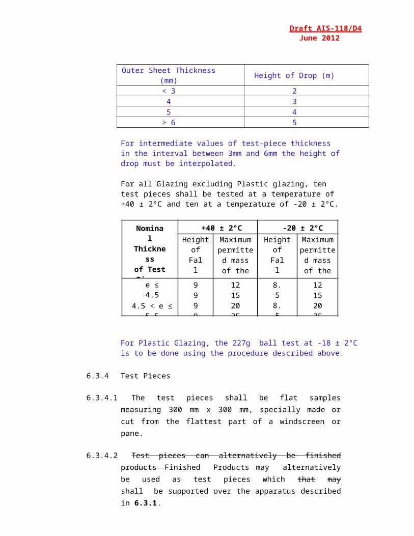
Draft AIS-118/D4June 2012
F igure 13: Ex a m pl e o f observat i on b y t he Coll i m ation-Telescope T e st Method
6.13.4 Test Pieces
6.13.4.1 The test pieces shall be windscreens.
6.14 Fire Resistance Test
6.14.1 Apparatus
6.14.1.1 Combustion Chamber
6.14.1.1.1 The combustion chamber is illustrated by Figure 14, having the dimensions given in Figure 15.
6.14.1.1.2 The combustion chamber is constructed of stainless steel.
6.14.1.1.3 The front of the chamber contains a flame-resistant observation window, which may cover the entire front and which can be constructed as an access panel.
6.14.1.1.4 The bottom of the chamber has vent holes, and the top has a vent slot all around.
Page 46 of 73
Draft AIS-118/D4June 2012
Figure 14: Ex a m pl e of C o m bustion Ch a m b e r with S a m p l e H o l d e r and D rip Pan
F i g ure 15: E x a m pl e o f C o m bustion Ch a m b e r
6.14.1.1.5 The combustion chamber is placed on four feet, 10 mm high. The chamber may have a hole at one end for the introduction of the sample holder containing the sample; in the opposite end, a hole is provided for the gas-supply line. Melted material is caught in a pan (Figure 16) which is placed on the bottom of the chamber between vent holeswithout covering any vent-hole area.
Page 47 of 73

F igu re 1 6: Ty pical D rip Pan
Draft AIS-118/D4June 2012
6.14.1.2 Sample Holder
6.14.1.2.1 The sample holder consists of two U-shaped metal plates or frames of corrosion proof material. Dimensions are given in Figure 17.
Figure 17: E xa mp le of Samp le Hold er
6.14.1.2.2 The lower plate is equipped with pins and the upper one with corresponding holes, in order to ensure a consistent holding of the sample. The pins also serve as measuring points at the beginning and end of the burning distance.
6.14.1.2.3 A support shall be provided in the form of heat-resistant wires0.25 mm in diameter spanning the frame at 25 mm intervals over the bottom U-shaped frame (Figure 18).
Page 48 of 73
Draft AIS-118/D4June 2012
Figure 18: Exa mple of section of lower U-frame Design for wire S upport Facility
6.14.1.2.4 The plane of the lower side of samples shall be 178 mm above the floor plate. The distance of the front edge of the sample holder from the end of the chamber shall be 22 mm; the distance of the longitudinal sides of the sample holder from the sides of the chamber shall be 50 mm (all inside dimensions). (Figures 14 and 15.)
6.14.1.3 Gas burner- The small ignition source is provided by a Bunsen burner having an inside diameter of 9.5 mm. It is so located in the test cabinet that the centre of its nozzle is 19 mm below the centre of the bottom edge of the open end of the sample (Figure 15).
6.14.1.4 Test gas- The gas supplied to the burner shall have a calorific value of about 38 MJ/m3 (for example natural gas).
6.14.1.5 Metal comb, at least 110 mm in length, with seven or eight smooth rounded teeth per 25 mm.
6.14.1.6 Stop-watch, accurate to 0.5 seconds.
6.14.1.7 Fume Cupboard
6.14.1.7.1 The combustion chamber may be placed in a fume-cupboard assembly provided that the latter internal volume is at least 20 times, but not more than 110 times greater than the volume of the combustion chamber and provided that no single height, width, or length dimension of the fume cupboard is greater than 2.5 times either of the other two dimensions.
6.14.1.7.2 Before the test, the vertical velocity of the air through the fume cupboard shall be measured 100 mm forward of and to the rear of the ultimate site of the combustion chamber.
Page 49 of 73
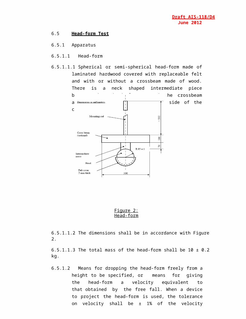
Draft AIS-118/D4June 2012
It shall be between 0.10 and 0.30 m/s in order to avoid possible discomfort to the operator from combustion products. It is possible to use a fume cupboard with natural ventilation and an appropriate air velocity.
6.14.2 Procedure
6.14.2.1 Conditioning. The samples shall be conditioned for at least 24 hours, but not more than 7 days, at a temperature of 20 ± 5 °C and a relative humidity of 60 ± 20 per cent and shall be maintained under these conditions until immediately prior to testing.
6.14.2.2 Place samples with napped or tufted surfaces on a flat surface, and comb twice against the nap using the comb (see 6.14.1.5.).
6.14.2.3 So place the sample in the sample holder (see 6.14.1.2.1.) that the inner side faces downwards, towards the flame.
6.14.2.4 Adjust the gas flame to a height of 38 mm using the mark in the chamber, the air intake of the burner being closed. The flame shall burn for at least one minute, for stabilization, before the first test is started.
6.14.2.5 Push the sample holder into the combustion chamber so that the end of the sample is exposed to the flame, and after 15 seconds cut off the gas flow.
6.14.2.6 Measurement of burning time starts at the moment when the foot of the flame passes the first measuring point. Observe the flame propagation on the side (upper or lower) whichever burns faster.
6.14.2.7 Measurement of burning time is completed when the flame has come to the last measuring point or when the flame is extinguished before reaching that point. If the flame does not reach the last measuring point, measure the burnt distance up to the point where the flame was extinguished. Burnt distance is the part of the sample destroyed, on the surface or inside, by burning.
6.14.2.8 If the sample does not ignite or does not continue burning after the burner has been extinguished, or the flame goes out before reaching the first measuring point, so that no burning time is measured, note in thetest report that the burning rate is 0 mm/min.
Page 50 of 73
Draft AIS-118/D4June 2012
6.14.2.9 When running a series of tests or performing repeat tests, make sure before starting a test that the temperature of the combustion chamber and sample holder does not exceed 30 ° C.
6.14.2.10 Calculation:
The burning rate B, in millimeters per minute, is given by the formula ;
where:‘s’ is the burnt distance, in millimeters,‘t’ is the time in seconds, taken to burn the distances.
6.14.3 Test Pieces
6.14.3.1 Shape and Dimensions
6.14.3.1.1 The shape and dimensions of samples are given in Figure 19. The thickness of the sample corresponds to the thickness of the product to be tested. It shall not be more than 13 mm. When sample-taking so permits, the sample shall have a constant section over its entire length.
F i g ure 1 9: Sa m p le
6.14.3.1.2 When the shape and dimensions of a product do not permit taking a sample of the given size, the following minimum dimensions shall be observed:
(a) For samples having a width of 3 to 60 mm, the length shall be356 mm. In this case the material is tested over the product width;
Page 51 of 73
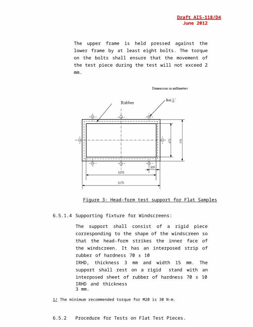
Draft AIS-118/D4June 2012
(b) For samples having a width of 60 to 100 mm, the length shall be at least 138 mm. In this case the potential burning distance corresponds to the length of the sample, the measurement starting at the first measuring point;
(c) Samples less than 60 mm wide and less than 356 mm long, and samples 60 to 100 mm wide and less than 138 mm long, cannot be tested according to the present method, nor can samples less than 3 mm wide.
6.14.3.2 Sampling
6.14.3.2.1 Five samples shall be taken from the material under test. In materials having burning rates differing according to the direction of the material (this being established by preliminary tests) the five samples shall be taken and be placed in the test apparatus in such a way that the highest burning rate will be measured.
6.14.3.2.2 When the material is supplied in set widths, a length of at least500 mm covering the entire width shall be cut. From the piece so cut, the samples shall be taken at not less than 100 mm from the edge of the material and at points equidistant from each other.
6.14.3.2.3 Samples shall be taken in the same way from finished products when the shape of the product so permits. If the thickness of the product is over 13 mm it shall be reduced to 13 mm by a mechanical process applied to the side which does not face the passenger compartment.
6.14.3.2.4 Composite materials shall be tested as if they were homogeneous.
6.14.3.2.5 In the case of materials comprising superimposed layers of different composition which are not composite materials, all the layers of material included within a depth of 13 mm from the surface facing towards the passenger compartment shall be tested individually.
6.15 Te s t of Res i s t ance to C h e m icals
6.15.1 Chemicals used for the test
6.15.1.1 Non-abrasive soap solution: 1% by mass of potassium oleate in deionized water;
Page 52 of 73

Draft AIS-118/D4June 2012
6.15.1.2 Window-cleaning solution: an aqueous solution of isopropanol and dipropylene glycol monomethyl ether in concentration between 5 and10% by mass each and ammonium hydroxide in concentration between1 and 5 per cent by mass;
6.15.1.3 Undiluted denatured alcohol: 1 part by volume methyl alcohol in 10 parts by volume ethyl alcohol;
Petrol or equivalent reference petrol: a mixture of 50 per cent by volume toluene, 30 per cent by volume 2, 2, 4-trimethylpentane, 15 per cent by volume 2, 4, 4-trimethyl-1- pentene and 5% by volume ethyl alcohol;
N.B: The composition of the petrol used shall be recorded in the test report.
6.15.1.4 Reference kerosene: a mixture of 50% by volume n-octane and 50 %by volume n-decane.
6.15.2 Procedure
6.15.2.1 Immersion Test
6.15.2.1.1 Test pieces shall be tested with each of the chemicals specified in6.15.1 above, using a new test piece for each test and each cleaning product.
6.15.2.1.2 Before each test, test pieces shall be cleaned according to the manufacturer's instruction, and then conditioned for 48 hours at the conditions specified in 6.1. These conditions shall be maintained throughout the tests.
6.15.2.1.3 The test pieces shall be completely immersed in the test fluid and held for one minute, then removed and immediately wiped dry with a clean absorbent cotton cloth.
6.15.2.2 Test Procedure Under Load – Applicable only for Rigid Plastic Glazing
6.15.2.2.1 The test specimen shall be simply supported as a horizontal level arm between a fixed supporting edge at one end in such a way that the entire width will rest on a cutting edge (fulcrum) which is 51mm from the fixed end support. A load shall be suspended from the free end of the test specimen at a distance of 102mm from the fulcrum as shown in the below figure.
6.15.2.2.2 The load mass shall be 28.7 t2 g where t is the thickness in mm of the test specimen. The resulting stress on the outer fiber of the test specimen is approximately 6.9Mpa.Eg: For a 3mm thick test specimen placed horizontally between a downward fixed edge and an upward fulcrum edge separated by 51mm the applied downward load at 102mm from the fulcrum is to be 258g.
6.15.2.2.3 While the test specimen is stressed, one of the prescribed chemicals shall be applied to the top surface of the test specimen above the fulcrum point. The chemical shall be applied with a soft, 13mm wide brush, wetted before each stroke. Ten individual strokes at 1S intervals across the width of the test specimen, avoiding the end and edges, shall be required. (See below figure)
6.15.3 Test Pieces
6.15.3.1 The test pieces shall be flat samples measuring 180 mm x 25 mm.
Page 53 of 73
Draft AIS-118/D4June 2012
6.16 Headform test with Deceleration Measurement for Plastic Glazing
6.16.1 Apparatus
In the case of headform tests with simultaneous determination of HIC-values the drop body is the phantom head as shown in Figure 20. The total mass of the phantom head should be 10.0 +0.2 /-0.0 kg.
In the middle of the base plate (24), the triaxial mounting block (26) is mounted in the center of gravity to receive the acceleration gauges (27). The acceleration gauges should be arranged vertically to each other.
The basin (18) and cover (19) situated under the baseplate (24) share, to a great extent, the elastic properties of the human skull. The elastic properties of the phantom head on impact are determined by the hardness and thickness of the intermediate ring (13) and the basin.
Figure 20
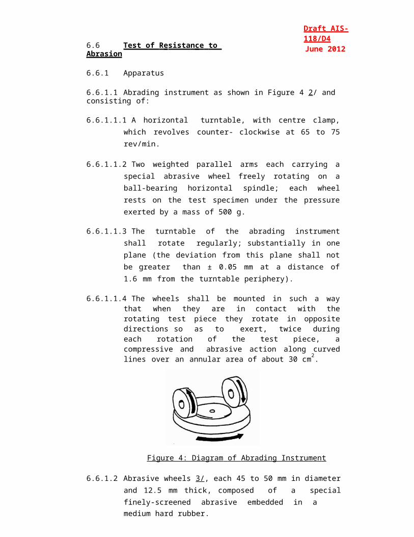
List of Pieces for the 10Kg headform concerning Figure 20
Position No.
Number of Pieces
Standard Notation Material Remarks
1 1 Magnetic Holding Device
Steel DIN 17100
2 1 Vibration Damper Rubber / Steel Diameter: 50mmThickness: 30mmThread: M10
3 4 HF Connector BNC - -4 1 Hexagonal Nut DIN
985- -
5 6 Disc DN 125 - -6 3 Transition piece - -7 6 Cylinder Screw DIN
912- -
8 3 Hexagonal Nut - -9 3 Disc Steel DIN 17100 Hole Diameter: 8mm
Outer Diameter: 35mmThickness: 1.5mm
10 3 Rubber Ring Rubber, hardness 60 IRHD
Hole Diameter: 8mmOuter Diameter: 30mmThickness: 10mm
11 1 Damping Ring Packing with Paper Hole Diameter: 120mmOuter Diameter: 199mmThickness: 0.5mm
12 - - - -13 1 Intermediate Ring Butadiene Rubber,
Hardness IRHD about 80
Hole Diameter: 129mmOuter Diameter: 192mmThickness: 4mm
14 3 Guide Tube Polytetrafluoroethylene (PTFE)
Inner Diameter: 8mmOuter Diameter: 10mmLength: 40mm
15 3 Hexagonal Nut - -16 3 Threaded Bolt DIN 976 - -17 3 Screwed Insert Cast Alloy DIN 1709-
GD-CuZn 37Pb-
18 1 Basin Polyamide 12 -19 1 Cover Butadiene Rubber Thickness: 6mm
Rib on one side20 1 Guide Bush Steel DIN 17100 -21 4 Counter Sunk Screw - -22 1 Damping Disc Packing with paper Diameter: 65mm
Thickness: 0.5mm
23 - - - -24 1 Base Plate Steel DIN 17100 -25 1 Set Screw with
Hexagonal SocketClass of Strength 45H -
26 1 Triaxial Mounting Block
- -
27 3 Acceleration Guage - -28 1 Wood Component Hornbeam, glued in
layers-
29 1 Cover Plate Alloy (AlMg5) -30 1 Protective Cap Polyamide 12 -
6.16.2 Adjustment and Calibration:
To perform the headform test, the phantom head is fixed to the cross-arm of the guide system (Figure 21) and moved to the required drop height by means of a lifting device. During the headform test, the cross arm with the phantom head is released. After passing the height adjustable light barrier the phantom head is released from the cross-arm, the cross-arm’s fall is dampened and the phantom head falls onto the sample.
No impulse may be given to the phantom head by the drop appliance or by the measuring cable, so that it is accelerated only by gravity and falls vertically.
Figure 21
6.16.2.1 Measuring device which allows to determine HIC-values with the headform described under 6.16.1.
6.16.2.2 Equipment to Calibrate the phantom head
The drop appliance must allow drop heights between 50mm and 254mm to be adjusted exactly to within 1mm. A guide system is not necessary for these small drop heights.
A steel impact plate which is made of steel is 600 x 600mm in size and atleast 50mm thick. The impact surface must be polished.
Surface Roughness Rmax = 1µm, flatness tolerance t = 0.05mm.
6.16.2.3 Calibration and adjustment of the phantom head
Before each test series and no later than each 50 tests within a series, the phantom head must be calibrated and adjusted if necessary.
The impact plate must be clean and dry and during the test must lie non-positively on a concrete base.
The phantom head is allowed to hit the impact plate vertically. The drop heights (measured from the lowest point of the phantom head to the surface of the impact plate) are 50, 100, 150 and 254mm. The deceleration curves should be recorded.
The greatest deceleration az from the various drop heights on the z-axis must lie within the limits given in the table.
Drop Height (mm) Greatest deceleration az as a multiple of acceleration due to gravity g
50 64 ± 5100 107 ± 5150 150 ± 7254 222 ± 12
The deceleration curves should be based on a unimodal vibration. The deceleration curve of the drop height of 254mm must run atleast 1.2ms and at most 1.5ms over 100g.
If the requirements given above are not met, the elastic properties of the phantom head must be adjusted by varying the thickness of the intermediate ring (13) in the base plate (24). The rubber rings (10) under the hexagon nuts (8) should not be brittle or cracked.
The cover (19) of the impact surface and the intermediate ring (13) should always be replaced immediately if damaged, especially when the phantom head can no longer be adjusted.
6.16.2.4 Supporting Fixture for testing flat test pieces as shown in figure 22, for testing flat test pieces. The fixture is composed of two steel frames, with machined borders 50mm wide, fitting one over the other and faced with rubber gaskets about 3mm thick and 15 ± 1mm wide and of hardness 70 IRHD. The upper frame is held pressed against the lower frame by at least 8 bolts.
6.16.3 Test Conditions:
Temperature : 20 ± 5°CPressure : 860 to 1060 mbarRelative Humidity : 60 ± 20%
6.16.4 Tests on complete panes (used for a drop height between 1.5m and 3m). Place the pane freely on a support with an interposed strip of rubber of hardness 70 IRHD and thickness of about 3mm.
The Pane shall be clamped to the supporting structure by means of appropriate devices. The surface of the pane shall be substantially perpendicular to the incident direction of the headform weight. The headform weight shall strike the pane at a point within 40mm of its geometric center on that face which represents the inward face of the plastic pane when the latter is mounted on the vehicle, and shall be allowed to make only one impact.
Starting from a selected initial drop height, the drop heights should be raised by 0.5m respectively in each further experiment. The deceleration curves occurring on impact on the sample for ax, ay and az should be recorded according to time t.
After the headform test, it should be checked whether a glazing edge has moved more than 2mm in the mount and whether the requirement for the point of impact was met. The acceleration components ax and ay should be smaller for vertical impact than 0.1 az.
Figure 22
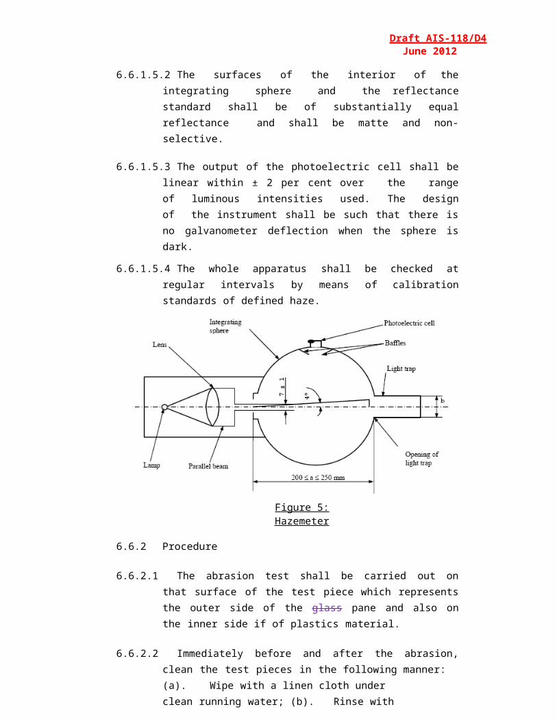
6.16.5 Evaluation
The deceleration curves should be evaluated as follows:
The resulting deceleration ares(t) in the center of gravity according to equation (1) from the measured deceleration curves ax(t), ay(t) and az(t) is to be compounded as multiples of the acceleration due to gravity.
The time for which a deceleration of 80g with ares is continually exceeded and the greatest deceleration of ares should be determined. The HIC-Value should be calculated as a measurement of the danger of blunt skull-brain-injuries using the following equation (2).
The integral limits t1 and t2 should be selected in such a way that the integral takes a maximum value.
6.17 Flexibility Test and Fold Test:
Scope:
With this test has to be found out whether a plastic is to be classed into the categories of rigid or flexible plastics.
Test Method:
From the material of the nominal thickness a rectangular flat sample 300mm long and 25mm wide is cut out and horizontally clamped into a clamping device in such a way that 275mm of the length of the sample freely extend over the holding device. This free end shall be supported horizontally by an appropriate device until the test begins. Sixty seconds after removal of this support, the vertical deviation of the free end is indicated in mm. If this deviation exceeds 50mm a 180° fold test is performed subsequently. The sample is folded concisely, after that it is folded round 0.5mm thick piece of sheet metal in such a way that it tightly contacts it on both sides.
Test Conditions:
Temperature: 20 ± 2°CRelative Humidity: 60 ± 5%
Requirements:
The vertical deviation must be more than 50mm for flexible plastics, and 10 seconds after a 180° - folding, the material must not show any fracture-like damages at the point of buckling (Figure 23).
6.18 Weathering
6.18.1 Apparatus
6.18.1.1 Long-Arc Xenon LampThe exposure apparatus (1) shall utilize a long-arc xenon lamp as the source of irradiation, but other methods giving the required level of ultraviolet radiant exposure shall be allowed. The long-arc xenon lamp is advantageous in that it can, when correctly filtered and maintained, yield a spectrum most closely approximating that of natural sunlight. To this end, the quartz xenon burner tube shall be fitted with suitable borosilicate glass optical filter(s) (2). The xenon lamps employed shall be operated, from a suitable 50 or 60 Hz power supply suitable reactance transformers and electrical equipment.
Figure 23
6.18.1.2 The exposing apparatus shall include equipment necessary for measuring and/or controlling the following:
- Irradiance- Black Standard Temperature- Water Spray- Operating schedule or cycle
The exposure apparatus shall be made from inert materials which do not contaminate the water employed in the test.
Irradiance shall be measured at the test specimen surface and shall be controlled according to the recommendations of the exposure apparatus manufacturer.
Total Ultraviolet Radiant Exposure (1) (Joules / per Square meter) shall be measured or computed and shall be considered the primary measure of test specimen exposure.
6.18.1.3 Test Specimens:The dimensions of the test specimen shall normally be those specified in the appropriate test method for the property or properties to be measured after exposure.
The number of control and test specimens for each test condition or exposure stage shall be determined, in addition to those required for visual evaluations by the number required by the test methods.
It is recommended that visual evaluations be conducted on the largest test specimens being tested.
6.18.1.4 Procedure:Measure according to 6.1, the luminous transmittance of the test specimen(s) to be measured. Measure according to 6.6, the resistance of abrasion of the surface(s) of the control specimen(s). The face of each test specimen, which would represent the surface glazed to the exterior of the road vehicle, shall face the lamp. Other exposure conditions shall be as follows.
6.18.1.4.1 The irradiance shall not vary more than ±10% over the whole test specimen area.
6.18.1.4.2 At appropriate intervals, clean lamp filters by washing with detergent and water. Xenon-arc filters shall be replaced according to the recommendations of the equipment manufacturer.
6.18.1.4.3 The temperature within the exposure apparatus during the dry portion of the cycle shall be controlled by circulation of sufficient air to maintain a constant black standard temperature.
In the Xenon arc exposure apparatus, this temperature shall be 70 ± 3°C as indicated by a black standard thermometer or equivalent.
The black panel thermometer shall be mounted in the test specimen rack and readings shall be taken at the point where maximum heat is developed due to
light exposure.
6.18.1.4.4 The relative humidity within the exposure apparatus shall be controlled at 50 ± 5% during the dry portions of the cycle.
6.18.1.4.5 The deionized water used in the spray cycle shall contain less than 1ppm silicon dioxide solids and shall leave no permanent deposit or residue on the test specimens which would interfere with subsequent measurements.
6.18.1.4.6 The pH of the water shall be between 6.0 and 8.0, and the conductivity shall be less than 5 microsiemens.
6.18.1.4.7 The temperature of water in the line where it enters the exposure apparatus shall be the ambient water temperature.
6.18.1.4.8 The water shall strike the test specimens, in the form of a fine spray in sufficient volume to wet the test specimens uniformly, immediately upon impact.
Water spray will be directed only against the test specimen surface facing the light source. No recirculation of the spray water or immersion of the test specimens in the water shall be permitted.
6.18.1.4.9 The test specimens shall be rotated about the arc in order to provide uniform distribution of the light. All positions in the exposure apparatus shall be filled with test specimens or surrogates to ensure that a uniform temperature distribution is maintained. Test specimens shall be held in frames with backs exposed to the cabinet environment. However, reflections from cabinet walls shall not be permitted to strike the back surface of specimens. If necessary, samples may be backed to block such reflections so long as free circulation of air at the specimen surface is not impeded.
6.18.1.4.10 The exposure apparatus shall be operated to provide continuous light and intermittent water spray in 2h cycles. Each 2h cycle shall be divided into periods during which the test specimens are exposed to light without water spray for 102 minutes and to light with water spray for 18 minutes.
6.18.1.5 Evaluation:After exposure, the test specimens may be cleaned, if necessary, by a practice recommended by their manufacturer to remove any residues present.
Evaluate the exposed test specimens visually with respect to the following properties.
- Bubbles- Colour- Haze- Noticeable decomposition
Measure the luminous transmittance of the exposed specimens.
6.18.1.6 Expression of Results:Report visual evaluations of exposed test specimens, comparing the appearance of each with that of the unexposed control.
The luminous transmittance measured must not differ from the original tests on unexposed samples by more than 5%.
(1) Total Ultraviolet is considered to be all radiation of wavelength less than 400nm.
6.19 Cross-cut test
6.19.1 Scope:The test gives a simple method to determine the adhesion of coatings to the subsurface. The brittleness and other strength characteristics can be evaluated.
6.19.2 Apparatus:Cutting tool with 6 blades set at 1mm apart. A magnifying glass with an enlargement of 2x to examine the cross-cut specimen (Figure 24)
6.19.3 Test MethodCut through the coating onto the subsurface a pattern with 6 cuts and perpendicular to this another one so that a grid with 25 squares arises (grid-cut).
Figure 24 – Tool with six blades
The cutting tool should be drawn steadily with a speed of 2 to 5cm/s so that the cuts reach the subsurface but do not penetrate too deeply.
The Cutting is conducted in such a way that the two leading heads at the edge of the apparatus touch the surface uniformly. After the test, the cuts are examined with a magnifying glass to check that they reach the subsurface. The test is carried out atleast at two different positions of the specimen. After the cuts have been produced, they are brushed five times with slight pressure in both diagonal directions with a hand brush with polyamide bristles.
6.19.4 Interpretation of Results:
The grid cuts are examined with a magnifying glass. If the cut edges are perfectly smooth and if no part of the coating is detached, then it will be given a cross-cut value of Gt0. If there are small fragments detached at the intersection of the cuts and if the exposed area amounts to about 5% of the grid area the cut value is Gt1.
Larger areas of detachment will be graded in the range Gt2 to Gt5.
Cut Value Grade Exposed area of the grid areaGt2 Between 5 and 15%Gt3 Between 15 and 35%Gt4 Between 35 and 65%Gt5 Higher than 65%
7 PO S ITI ON OF P O I NTS
7.1 Annex 7.1 . Procedures for determining test areas on windscreens of Category 1-1 M1and 2 N (based on derived from a 1-1 M1 where the windscreen and seating positions are identical) vehicles in relation to the "V" Points and Category 1-2 M and N and 2 (except M1 and those based on N derived from a 1-1 M1 where the windscreen and seating position are identical) vehicles in relation to the "O" point.
7.1.1 Position of the "V" points
7.1.1.1 The position of the "V" points in relation to the "R" point as indicated by the X Y and Z co-ordinates in the three-dimensional reference system, are shown in Tables 1 and 2.
7.1.1.2 Table 1 gives the basic co-ordinates for a design seat-back angle of25°. The positive direction of the co-ordinates is shown in this annex, Figure 3.
Tab le 1
"V" Point A b c(d)
V1
V2
68 mm
68 mm
-5 mm
-5 mm
665 mm
589 mm
7.1.1.3 Correction for Design Seat-Back Angles other than 25°.
7.1.1.3.1 Table 2 shows the further corrections to be made to the X and Z co- ordinates of each "V" point when the design seat-back angle is not25°. The positive direction of the co-ordinates is shown in this annex,Figure 3.
Page 54 of 73
Draft AIS-118/D4June 2012
Tab le 2Seat-back Angle (in
°)
Horizontal co-ordinates
X
Verticalco-ordinates
Z
Seat-back angle (in °)
Horizontal co-ordinates
X
Verticalco-ordinates
Z56789
10111213141516171819202122
- 186 mm- 177 mm- 167 mm- 157 mm- 147 mm- 137 mm- 128 mm- 118 mm- 109 mm- 99 mm- 90 mm- 81 mm- 72 mm- 62 mm- 53 mm- 44 mm- 35 mm- 26 mm
28 mm27 mm27 mm27 mm26 mm25 mm24 mm23 mm22 mm21 mm20 mm18 mm17 mm15 mm13 mm11 mm9 mm7 mm
232425262728293031323334353637383940
- 18 mm- 9 mm
0 mm9 mm
17 mm26 mm34 mm43 mm51 mm59 mm67 mm76 mm84 mm92 mm
100 mm108 mm115 mm123 mm
5 mm3 mm0 mm
- 3 mm- 5 mm- 8 mm- 11 mm- 14 mm- 18 mm- 21 mm- 24 mm- 28 mm- 32 mm- 35 mm- 39 mm- 43 mm- 48 mm- 52 mm
7.1.2 Position of the "O" Point
7.1.2.1 The eye-point "O" is the point located 625 mm above the R-point in the vertical plane parallel to the longitudinal median plane of the vehicle for which the windscreen is intended, passing through the axis of the steering wheel.
7.1.3 Test Areas
7.1.3.1 The test areas shall be determined as follows:
7.1.3.2 For Optical Distortion and Image Separation Measurement:In case of Category 1-1 M1and 2 N (based on derived from a 1-1 M1 where the windscreen and seating positions are identical) vehicles according to paragraph 7.1.3.2.
In case of Category 1-2 M and N an d 2 (except those bas ed on M1 and N category derived from a 1- 1 M1 where the windscreen andseating position are identical) vehicles according to parag raph.
Page 55 of 73
Draft AIS-118/D4June 2012
7.1.3.2.1 For the measurement of the Light Transmittance in the transparent area of the windscreen according to 7.1.3.4.
7.1.3.3 Determination of two test areas for Category 1-1 M1and 2 N (bas ed on derived from a 1-1 M1 where the windscreen and seating positions are identical) vehicles using the "V" points.
7.1.3.3.1 “Test area A” is the area on the outer surface of the windscreen bounded by the following four planes extending forward from the "V" points [see Figure 1 and 2(c)]:
a) A plane parallel to the Y axis passing through V1 and inclined upwards at 3° from the X axis (plane 1);
b) A plane parallel to the Y axis passing through V2 and inclined downwards at 1° from the X axis (plane 2);
c) A vertical plane passing through V1 and V2 and inclined at 13° °to th e l eft o f the ax is in t he cas e of l eft-hand driv e vehicles and to the right of the X axis in the case of right- hand drive vehicles and central drive vehicles (plane 3);
d) A vertical plane passing through V1 and V2 and inclined at 20° to th e rig ht of the X ax is in the case of left-h and drive v ehi cles an d to the left of the X axis in the case of right-hand drive vehicles and 13° to the right of the X axis in the case of central drive vehicles (plane 4).
7.1.3.3.2 The "extended test area A" is Zone A, extended to the median plane of the vehicle, and in the corresponding part of the windscreen symmetrical to it about the longitudinal median plane of the vehicle, and also in the reduced test area B according to 7.1.3.2.4.
7.1.3.3.3 “Test area B” is the area of the outer surface of the windscreen bounded by the intersection of the following four planes (see Fig. 2):a) A plane inclined upward from the X axis at 7°, passing through
V1 and parallel to the Y axis (plane 5);b) A plane inclined downward from the X axis at 5°, passing
through V2 and parallel to the Y axis (plane 6);c) A vertical plane passing through V1 and V2 and forming an
angle of 17° to the right of the X axis in the case of right-hand drive vehicles (plane 7);
d) A plane symmetrical with respect to the plane 7 in relation to thelongitudinal median plane of the vehicle (plane 8).
Page 56 of 73
Draft AIS-118/D4June 2012
7.1.3.3.4 The "reduced test area B" is test area B with the exclusion of the following areas 5/ (see Figures 2 and 3):
7.1.3.3.4.1 The test area A defined under 7.1.3.2.1, extended according to7.1.3.2.2;
5 / But taking into account the fact that the datum points as defined under paragraph 7.1.3.2.5. shall be located in the transparent area.
7.1.3.3.4.2 At the discretion of the vehicle manufacturer, one of the two following paragraphs may apply:
7.1.3.3.4.2.1 Any opaque obscuration bounded downwards by plane 1 and laterally by plane 4 and its symmetrical in relation to the longitudinal median plane of the vehicle (plane 4');
7.1.3.3.4.2.2 Any opaque obscuration bounded downwards by plane 1, provided it is inscribed in an area 300 mm wide centered on the longitudinal median plane of the vehicle, and provided the opaque obscuration below the plane 5 trace is inscribed in an area limited laterally by the traces of planes passing by the limits of a 150 mm wide segment 6 / and parallel respectively to the traces of planes 4 and 4';
7.1.3.3.4.3 Any opaque obscuration bounded by the intersection of the outer surface of the windscreen:
a) With a plane inclined downwards from the X axis at 4°, passing through V2, and parallel to the Y axis (plane 9);
b) With plane 6;c) With planes 7 and 8 or the edge of the outer surface of the
windscreen if the intersection of plane 6 with plane 7 (plane 6 with plane 8) does not cross the outer surface of the windscreen;
7.1.3.3.4.4 Any opaque obscuration bounded by the intersection of the outer surface of the windscreen:
a) With a horizontal plane passing through V1 (plane 10);b) With plane 3 7/;c) With plane 7 8/ or the edge of the outer surface of the
windscreen if the intersection of plane 6 with plane 7 (plane 6 with plane 8) does not cross the outer surface of the windscreen;
d) With plane 9;
Page 57 of 73
Draft AIS-118/D4June 2012
7.1.3.3.4.5 Any opaque band situated within planes P3/P7 and P5/P10 respectively that does not extend by more than 25 mm from the edge of the design glass outline.
7.1.3.3.4.6 An area within 25 mm from the edge of the outer surface of the windscreen or from any opaque obscuration. This area shall not impinge on the extended test area A.
6 / Measured on the outer surface of the windscreen and on the trace of plane 1.7 / For the other side of the windscreen, with a symmetrical plane with respect to plane 3 in relation to the longitudinal median plane of the vehicle.8 / 7 for the other side of the windscreen, with plane 8
7.1.3.3.5 Definition of the datum points (see Figure 3)
The datum points are points situated at the intersection with the outer surface of the windscreen of lines radiating forward from the V points:
7.1.3.3.5.1 upper vertical datum point forward of V1 and 7° above the horizontal(Pr1);
7.1.3.3.5.2 lower vertical datum point forward of V2 and 5° below the horizontal(Pr2);
7.1.3.3.5.3 horizontal datum point forward of V1 and 17° to the right (Pr3);
7.1.3.3.5.4 Three additional datum points symmetrical to the points defined under7.1.3.2.5.1 to 7.1.3.2.5.3. in relation to the longitudinal median plane of the vehicle (respectively Pr'1, Pr'2, Pr'3).
Page 58 of 73
Draft AIS-118/D4June 2012
Figure 1: Te st ar ea "A"
(E x a m p le of a Righ t - h a n d S t e e ring Control Vehic l e)
Page 59 of 73
Draft AIS-118/D4June 2012
Figure 2(a): Red u ced T est Area "B" (Ex a m p l e of a Right-Hand S t eering Control Ve h icl e ) Upper obscura t i on a r ea as def i n e d in 7.1.3 . 2.4.2.2 .
Page 60 of 73
Draft AIS-118/D4June 2012
F igure 2(b): Red u ced test a r e a "B" (exa mp le of a Right-Han d S teering Control Vehicle)
Upper O bscuration Area as def ined in 7.1.3.2 .4.2.1.
Page 61 of 73
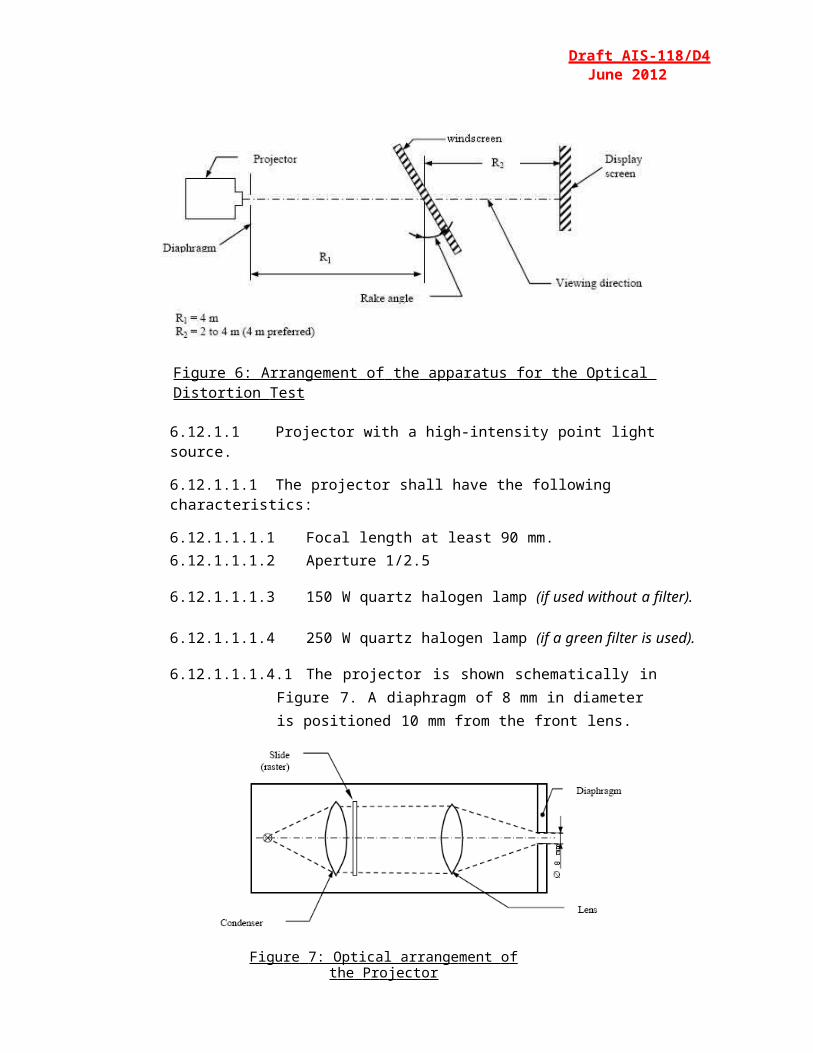
Draft AIS-118/D4June 2012
F i gure 2(c) : Test area “a” (Ex a m p le of C e n t r a l Ste e ring Co n t r o l V e hicle)
CL : trace of the longitudinal median plane of the vehicle andPi : trace of the relevant plane (see text)
Page 62 of 73
Draft AIS-118/D4June 2012
F igure 2 (d) – Cen tral A rea and O uter A rea o f the Windscreen.
Page 63 of 73
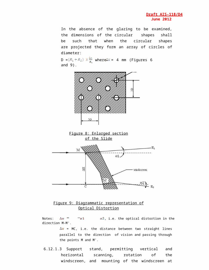
Draft AIS-118/D4June 2012
Figure 3: Deter min ation o f the D atu m P oin ts
(Exa m p le of a Right-Hand Steering Control Ve h i cle)
7.1.3.4 Determination of the Test Areas for Category M and N and 2 (except those b as ed on M1 and N derived from a 1-1 M1 where the windscreen and seating position are identical) Vehicles using the "O" Point.
7.1.3.4.1 The straight line OQ which is the horizontal straight line passing through the eye point "O" and perpendicular to the median longitudinal plane of the vehicle.
7.1.3.4.2 Zone I is the zone determined by the intersection of the windscreen with the four planes defined below:
P1 a vertical plane passing through 0 and forming an angle of 15° to the l eft right of the median longitudinal plane of the vehicle;
P2 a vertical plane symmetrical to P1 about the median longitudinal plane of the vehicle.
If this is not possible (in the absence of a symmetrical median longitudinal plane, for instance) P2 shall be the plane symmetrical to P1 about the longitudinal plane of the vehicle passing through pointO.
Page 64 of 73
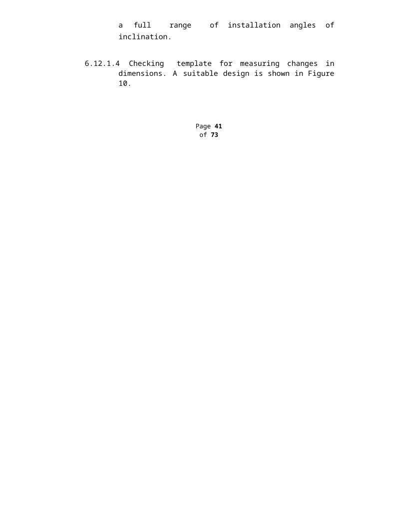
Draft AIS-118/D4June 2012
P3 a plane passing through a transverse horizontal line (line OQ)containing O and forming an angle of 10° above the horizontal plane;
P4 a plane passing through a transverse horizontal line (line OQ)containing O and forming an angle of 8° below the horizontal plane;
Figure 4: D e te r m i n ation of Zone I
7.1.3.5 Determination of the test area for light transmittance for all vehicle categories
The test area for light transmittance is the transparent area, excluding any opaque obscuration and any shade band. For practical reasons relating to the method of mounting and means of installation, it is accepted that a windscreen may incorporate an obscuration band which extends by not more than 25 mm from the edge of the design glass outline.Additional opaque obscuration is also allowed in limited areas where it is intended that a sensing device, e.g. a rain-drop detector or rear view mirror, will be bonded to the inner side of the windscreen. The allowed areas where such devices may be applied are defined in 7.1.3.2.4 ofthis annex.
Page 65 of 73
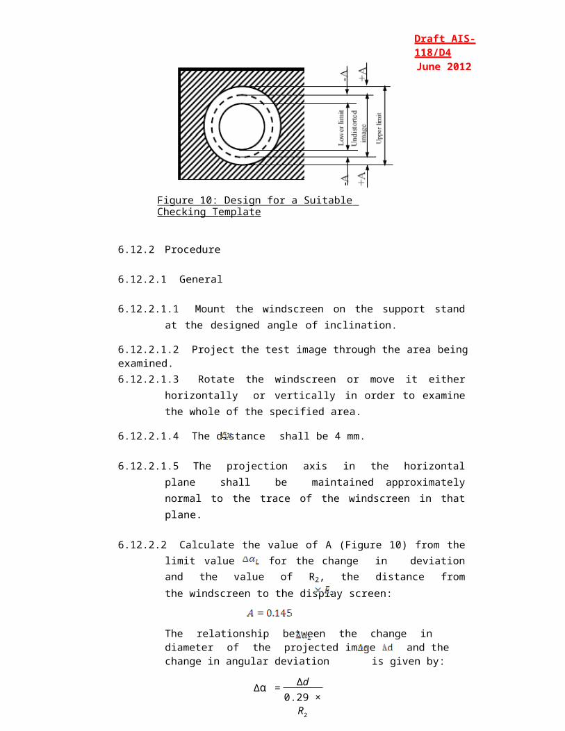
Draft AIS-118/D4June 2012
7.1.4 Central Area and Outer Area of Wind Screen
That part of the windscreen through which the principal afield of view is obtained [see fig 2 (d)] is called the central area of windscreen. It is also called primary vision area of the windscreen. The remaining area is considered outer area.
7.2 Meas ur e m e nt of the h e ight of se g m ent and posit i on of the po i nts of i m p a ct
h = h1 + h2
F igu re 1 : D eter min at ion of the Heigh t of Seg men t " h"
In the case of glazing having a simple curvature, the height of segment will be equal to: h1 maximum.
In the case of glazing having a double curvature, the height of segment will be equal to: h1 maximum + h2 maximum.
2(a) Flat Glass Pane
Page 66 of 73
Draft AIS-118/D4June 2012
2(b) Flat Glass Pane
2(c) Curved Glass Pane
F igure 2: P res cr ibed po ints of i mp act for Uniformly To ughened Glas s Pan es
Page 67 of 73
Draft AIS-118/D4June 2012
8 APPLI C A T ION F O R TYPE APPRO V AL OF S AFETY GL A Z I NG
8.1 Information to be submitted at the time of applying for Type Approval of Safety Glazing shall be as given in Annex A.
8.2 The application shall be accompanied with requisite number of samples and/or test pieces.
Annex A
Sr. No. Description Information to be submitted
A.1 Name and Address of theManufacturer
A.2 Manufacturing Plant and Address
A.3 Part Number or Unique Identification mark
A.4Intended use(windscreen/rear windscreen/window pane)
A.5 Designed thickness of glazing with tolerance
A.6
Type of Glazing (laminated / uniformly toughened / Glass plastic / Glazing Faced with plastic / in case of double glazed – Symmetrical or Asymmetrical/ Plastic –Rigid / Plastic - Flexible)
A.7 Designed Angle of Inclination in case of windscreen.
A.8Drawing of the safety glazing in triplicate indicating relevant dimensions and location for marking,
A.9Description of Glazing(Clear+Clear, Clear +Green, with shade band) etc.
A.10 Range of angle of inclination
Page 68 of 73
9 C ONFORMITY OF PR OD UC TION (COP)
Draft AIS-118/D4June 2012
9.1 The Requirements of COP shall be as specified in Clause No. 10.
9.2 Normal Frequency of COP shall be 2 years.
9.3 In case a Type approval as per AIS 037 has already been granted as per IS 2553 (part 2) 1992, the same shall be extended as per this standard provided the requirements laid down in Clause 12.3 are complied with.
10 ACCEPT A NCE TESTS (CONF O R M ITY OF P R O D U C TI O N TEST S )
10.1 Following Tests shall be done at a frequency of once in Two years.
Test
Windscreens Panes
LaminatedGlass
GlassPlastics
Uniformly Toughened
Glass
LaminatedGlass
Double Glazed unit 1/
GlassPlastics
Marking II II/P III I I/P IV IV/P V VI
LightTransmittance 5.1.1. 5.1.1. 5.1.1. 5.1.1. 5.1.1. 5.1.1. 5.1.1. 5.1.1. 5.1.1.
Resistance to High
Temperature/ Boil Test
5.3.2. 5.3.2. 5.3.2. 5.3.2. 5.3.2. 5.3.2. 5.3.2.
OpticalDistortion 5.4.1. 5.4.1. 5.4.1.
Secondary Image
Separation5.4.2. 5.4.2. 5.4.2.
Fragmentation 5.5.1.1. 5.5.1.1.
Head-formTest 5.4.3. 5.4.3. 5.4.3. 5.5.3.2.
2,260 g Ball 5.4.4. 5.4.4. 5.4.4.
1 / Each component pane shall satisfy the appropriate tests for the type of glazing.
Page 69 of 73
11 EX TENSION OF A PPR OVALS
Draft AIS-118/D4June 2012
11.1 Every modification pertaining to the information, even if the changes are not technical in nature declared in accordance with Annex A shall be intimated by the manufacturer to the Testing Agency.If the changes are in parameters not related to the provisions, no further action need be taken.If the changes are in parameters related to the provisions, the testing agency, which has issued the certificate of compliance, shall then consider, whether,
11.1.1 the safety glazing with the changed specifications still complies with provisions, or
11.1.2 Any further verification is required to establish compliance,
11.2 For considering whether testing is required or not, guidelines given in11.5 (Criteria for Extension of Approval) shall be used.
11.3 In case of 11.1.2, tests for only those parameters which are affected by the modifications need be carried out.
11.4 In case of fulfillment of criterion of 11.1.1 or after results of further verification as per 11.1.2 are satisfactory, the approval of compliance shall be extended for the changes carried out.
11.5 Criteria for Extension of ApprovalThe Criteria shall be as agreed between the testing agency and applicant or manufacturer.
Sr. No. Parameter / Criteria Whether verification is
required.1 Change in Type of Glazing from: -
1.1 Laminated to Glass plastic / GlazingFaced with plastic / Double glazed All Tests Required.
1.2Uniformly toughened glass to Glass plastic / Glazing Faced with plastic / Double glazed
Fragmentation Test
2Change in shape of Windscreen Glazing or Uniformly Toughened Window panes retaining the thickness same.
No Verification required.
Page 70 of 73
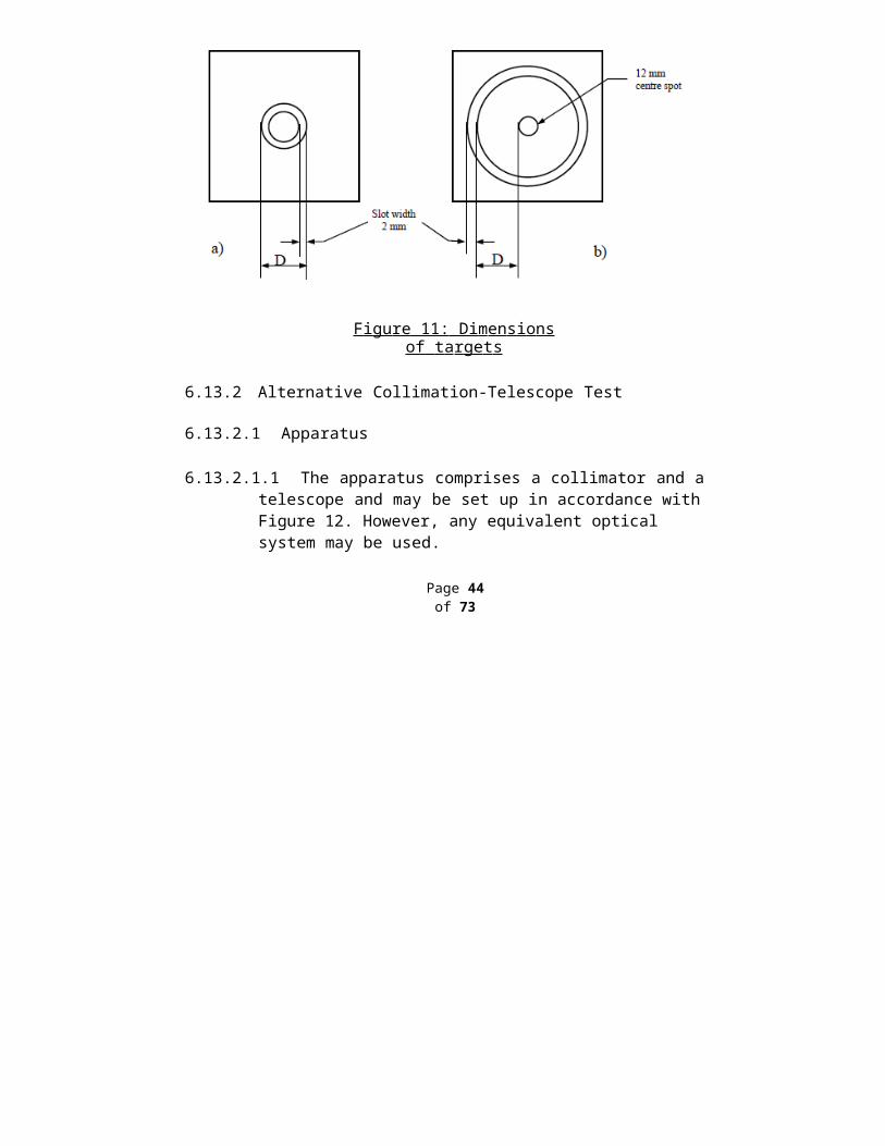
Draft AIS-118/D4June 2012
Sr. No. Parameter / Criteria Whether verification is
required.3 Change in Nominal Thickness of Windscreen:-
3.1 If the thickness is within the tolerance No Verification Required.
3.2 Increase in Thickness
Optical Distortion, Secondary Image and Light
Transmission Tests are Required
3.3 Decrease in thickness All tests are required.
4 Change in Rake Angle in case of windscreen
Optical Distortion, Secondary Image separation and Light Transmission tests
are Required.
5Change in location of the ‘R’ / ‘H’ / ‘O’ point w.r.t windscreen as mounted on vehicle.
In case the areas referred to in 5.4.1 and 5.4.2 are reduced
maintaining the overall boundaries same, no tests are
required.In case the boundaries are
shifted and / or area is increased, optical distortion
and secondary image separation tests need to be
carries out.6 Change in test area in case the earlier approval is based on fig 2 (d):-
6.1 Increase in Area
In case the boundaries are shifted and / or area is
increased, optical distortion and secondary image
separation tests need to be carries out.
6.2 Decrease in Area
If area is reduced maintaining the overall boundaries same,
no tests are required.
7 Change in Colour combination i.e. Cl+Cl or Cl + Green etc
Light Transmission, Optical Distortion and Secondary Image separation Test are
Required.
11.6 The Criterion for Extension of approvals in case of Glass plastic / Glazing Faced with plastic / double glazed shall be as agreed betweenthe manufacturer and Test Agency.
Page 71 of 73
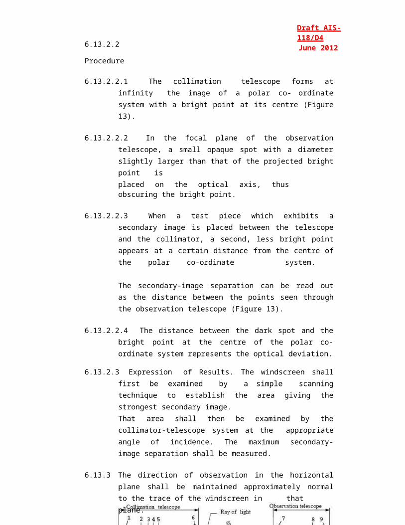
Draft AIS-118/D4June 2012
12.0 T R ANSIT I ON A L P R OVISI O NS
12.1 At the request of the applicant, Type Approvals for compliance to AIS: 118/20XX, shall be granted by test agencies from (date) Such Type Approvals shall be deemed to be compliance to IS 2553 (Part 2)/1992. (Date to be filled up based on date of adoption by CMVR TSC).
12.2 At the request of applicant, Type Approval to the compliance to IS2553 (Part 2)/1992 shall be granted up to the notified date of implementation of AIS: 118/20XX.
12.3 Type approvals issued for compliance to IS 2553 (Part 2)/1992 shall be extended to approval of AIS:118/ 20XX, subject to satisfactory compliance of the following:
12.3.1 In case of Double glazed units, Glass Plastics and Glazing faced with plastics, all tests specified in this standard.
12.3.2 In case of windscreen and Window Panes made of Laminated Glass: -
12.3.2.1 O ptical distortion t es t, in case the earli er resu lts do no t satis fy the require ments of this stan dard. [Since alternate method as per IS:2553- (Part 2/1992) has been adopted in AIS:118].
12.3.2.2 2,260 g ball test. [Since as per AIS: 118, No. of samples required are12 Nos. as compared to 06 Nos. as per IS: 2553-(Part 2/1992].
12.3.2.3 Resistance to Abrasion
12.3.2.4 Test for Resistance to Humidity
12.3.3 In case of Window Panes made of Uniformly Toughened Glass: -
12.3.3.1 Fragmentation test (for Curved Panes only).
Page 72 of 73
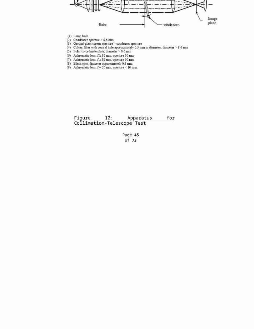
Draft AIS-118/D4June 2012
ANN E X B (See Introduction)
COMPOSITION OF PANEL ON SAFETY GLAZING*
(To be included)
A N N E X C (See Introduction)
COMMITTEE COMPOSITION Automotive Industry Standards Committee
(To be included)
Page 73 of 73