Embed Size (px)
Citation preview
G. Madhusudhan Reddy et al
Indian Society for Non-Destructive Testing Hyderabad Chapter
Proc. National Seminar on Non-Destructive Evaluation Dec. 7 - 9, 2006, Hyderabad
Microstructure, Residual Stress Distribution and Mechanical Properties of
Friction-Stir AA 6061 Aluminium Alloy Weldments
G. Madhusudhan Reddy1, P. Mastanaiah2, C.V.S. Murthy2 , T.Mohandas1 and N. Viswanathan2
1. Defence Metallurgical Research Laboratory, Hyderabad - 500 058, India 2. Defence Research Development Laboratory, Hyderabad -500 058, India
e-mail: [email protected]
Abstract Modern structural concepts demand reductions in both the weight as well as the cost of the production and fabrication of materials. Therefore welding processes have proven more attractive, and programs have been set up to study their potential. Friction stir welding (FSW) a solid state welding process is currently considered to be most prospective welding processes. It is generally believed that residual stresses are low in friction stir welds due to low temperature solid-state process of FSW. However, compared to more compliant clamps used for weld joint alignment in conventional fusion welding processes, the rigid clamping used in FSW exerts a much higher restraint on the welded plates. These restraints impede the contraction of the weld nugget and heat affected zone during cooling, thereby resulting in generation of residual stresses. It is well known that it is necessary to minimize or eliminate residual stresses so as to overcome assembly related problems during the in service stage. Microstructure, residual stress distribution across the weldments and mechanical properties were studied in the as-welded, post weld aging (PWA) and post weld solution treatment and aged (PWSTA) conditions. Optical microscopy revealed that the elongated pancake microstructure of the base material transformed into dynamically recrystalized microstructure of considerably smaller grain size in the weld nugget. Micro hardness measurements and tensile tests showed that the thermo-mechanically affected region is the weakest region of the weld. The weld joint exhibited reduced strength and ductility as compared to base material. The experimental results indicated that the parent material condition has a significant effect on residual stresses, weld macrostructure and mechanical properties of joints. Results also indicate that the transverse residual stress distribution profiles across the weld region are asymmetric with respect to weld centreline, with the largest residual stress gradients occurring on the advancing side of the weld. Within the region inside the shoulder diameter, residual stress is entirely compressive. Residual stress distribution across the weldment after PWSTA treatment is uniform thought the weldment and the sign of stresses are tensile in nature. Key words: Friction-stir welding, residual stresses, microstructure, hardness, and mechanical properties 1. Introduction There is an increasing need for low distortion aluminum alloys in sheet and plate form in the fabrication industry, such as ship panels, bridge decks and other transportation applications such as train and airplane components. Large extrusion presses and rolling mills are employed for these parts, with resultant high production costs. Extrusion has a limitation with respect to size and capacity. Therefore, sound welding methods are necessary to fabricate large Al alloy sheet and plate. Among aluminum alloys aluminum–magnesium–
Microstructure, Residual Stress Distribution
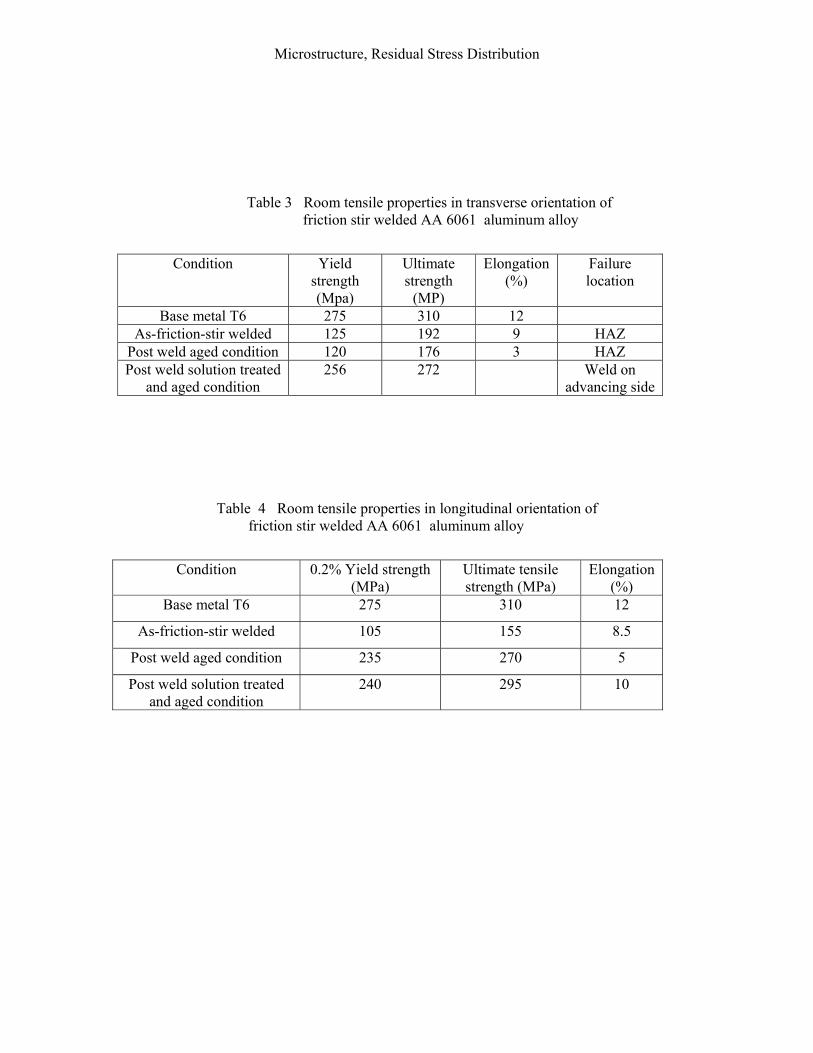
silicon (Al-Mg-Si) heat treatable wrought alloys, although of only medium strength, appears to have weldability advantage over high strength aluminum alloys. For this reason Al-Mg-Si alloys are widely used for structural components in welded assemblies. However, Al-Mg-Si alloys (6xxx series) are crack sensitive when they are fusion welded without filler metal [1]. If 6xxx series aluminum alloys are welded employing matching filler or filler from 5xxx series, cracking occurs in the partially melted zone (PMZ) as the weld zone solidifies first compared to the liquid phases in the PMZ. To circumvent this cracking problem these alloys are welded with 4xxx, which possess high fluidity and exhibit lowest melting point. However, when such fillers are employed the weld zone doesn’t respond to post weld aging, as sufficient magnesium is not present for the precipitation of Mg2Si, which is the main strengthening phase. However, these welds may respond to solution treatment and aging (STA). The degree of response to STA is dependent on the extent of dilution with the parent metal [2]. Thus, usage of 4xxx filler in general does not satisfy the property requirements. Fusion welding of precipitation hardenable aluminum alloys produces a fusion zone consisting of an cast coarse microstructure with solute gradients near the dendrite boundaries [3]. In addition, strengthening precipitates are dissolved during fusion welding when welded in STA condition. These microstructural changes often lead to a significant deterioration of strength in the weld. Post weld aging to restore mechanical properties is not effective because of solute loss in the matrix introduced by the solute segregation. Solution treatment and aging are needed to effectively improve the weld properties, but post weld solution treatment was assumed to be impractical for many applications of welded components. Solid state welding processes can offer a solution to the problems encountered in fusion welding of aluminum alloys. Friction-stir (FS) welding does not produce as-cast coarse microstructure and solute segregation in the welds because it is a solid state processes [4]. The benefits that stand out most are welding of difficult-to-weld aluminum alloys, better retention of base material properties, fewer weld defects, better dimensional stability of the welded structure. Although the weld material remains in the solid state throughout the joining process, It is exposed to a high temperature excursion [5-6] and experiences high levels of deformation [7], leading to significant modification of the microstructure and mechanical properties [8-9] coupled with development of considerable levels of residual stress [10]. Investigations of durability characteristics are underway. A significant potential contributor to the durability behaviour of FSW joints and surrounding material, however, will be the magnitude and distribution of residual stress imparted by the FSW process. An understanding on the mechanisms associated with microstructure and residual stress development and their influence on mechanical properties is important to optimize the mechanical properties. The aim of the present work is to make a detailed assessment of the microstructure, residual stress distribution and mechanical properties of AA 6061-T6 friction stir weldments. 2. Experimental details The parent metal used in the present study was 6.5 mm thick 6061-T6 aluminum alloy plate, whose chemical composition and mechanical properties provided in Table 1. The samples 150 X 75 mm were longitudinally but welded using 3-axis CIMTRIX make computer numerical controlled milling machine with FANUC controller (Fig.1). Specially designed tool made of tool steel has frustrum shaped probe with threads (Fig. 2) used in this study. The welding tool dimensions and welding parameters are listed in Table 2.
G. Madhusudhan Reddy et al
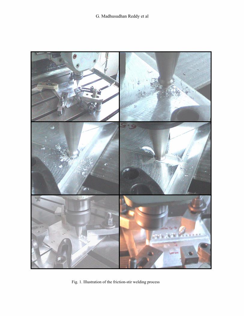
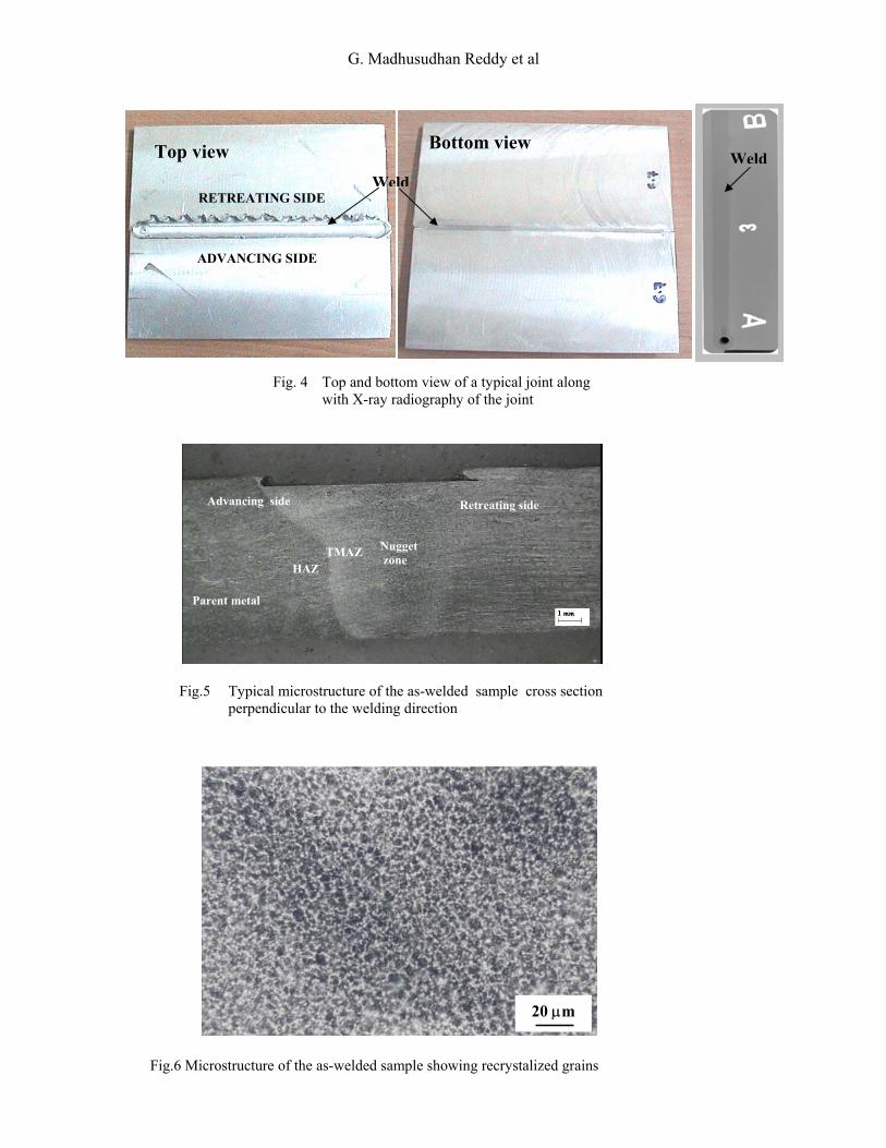
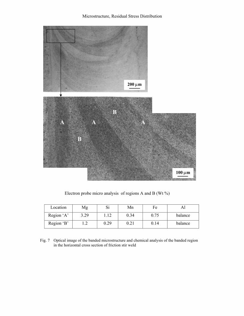
The residual stresses were measured by X-ray diffraction. The X-ray technique measures stresses indirectly by measuring the surface strain, which is indicated by the position of a diffraction peak for crystal planes, oriented at various angles to the surfaces of a specimen [11]. Residual stresses were measured using peak shift sin 2 ψ technique with CrKα radiation. The X-ray stress system and the measurement setup are shown in Fig. 3. For computation of the stresses from the measured strain data, appropriate X-ray elastic constants were used. The Oxide layer present on the surface was mostly removed by electrolytically followed by electrochemical polishing. The microstructures of different sections of the weld were examined after conventional metallographic sample preparation techniques and after etching with Keller’s reagent. Tensile specimens were extracted from longitudinal and transverse section of the weld. The specimen geometry conformed to ASTM E8 (25 mm gauge length). Testing was carried out on Instron 1185 universal testing machine at a crosshead speed of 1mm/minute. Hardness tests were carried out using Vickers hardness tester. The micro-hardness was measured at intervals of 0.5 mm across the weldments. The micro-hardness measurements were carried out mid section on thickness. Bend testing was carried out on face and root side as per ASTM E190 standard 3. Results and discussion 3.1 Inspection of FSW joint Top and bottom view of a typical joint along with X-ray radiography of the joint are shown in Fig. 4., it is clearly seen that a sound joint was obtained. 3.2 Optical metallography Fig. 5 Shows the macrostructure of the as-friction stir weld. The overall macrostructure is consistent with the observations in the literature [12-15]. The stirred zone, i.e., the weld nugget or dynamically recrystalized zone, approximately coincides with the shape of the tool and contains fine, equiaxed grains. On both sides of the stir zone are thermo-mechanically affected zone (TMZ), which contain highly deformed grains from the stirring action. The macrograph shows the lack of symmetry along the centerline of the weld. The advancing side (the edge of the weld where direction of tool rotation is the same as the travel) of the weld nugget is typically sharp and readily discernable; whereas the retreating side (the direction of tool rotation is opposite to the travel) of the weld nugget is much more diffuse. This is due to the torsion (due to rotating motion of the tool) and the circumventing (due to the translation motion of the tool) velocity fields having opposite directions on the advancing side, whereas these velocities have the same direction on the retreating side. The fine recrystallized zone at the weld nugget is due to heavy plastic deformation followed by dynamic recrystallization due to thermo-mechanical processing (Fig.6). Fig. 7 Show the banded structure in the as-friction weld. It can be seen that the weld exhibit two discernable bands, the bands are arbitrarily labeled as bands A and B, with band A being the dark etching band. Electron probe micro-analysis (EPMA) of these regions of A and B are shown in Fig.7. EPMA results demonstrate that dark region contain higher concentration of Si, Mn, Fe and Mg than the surrounding material. The composition trends are consistent with identification of the particles typical to those in 6XXX series aluminum alloys [16]. To determine the effect of

Microstructure, Residual Stress Distribution
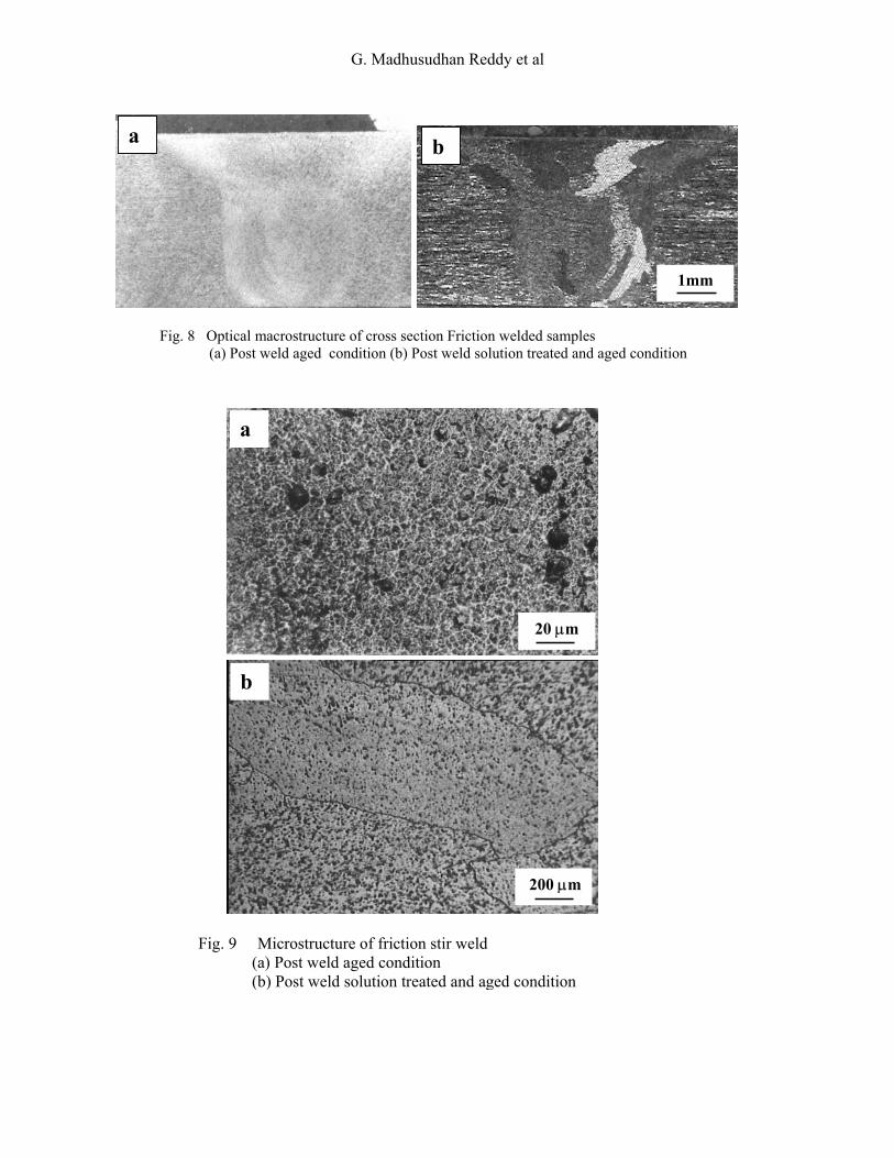
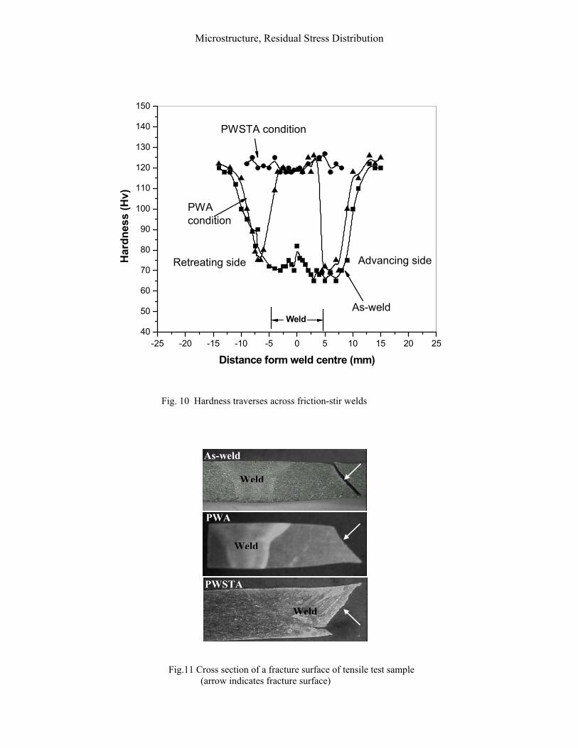
this variation on material properties, micro-hardness tests were performed across then banded microstructure. Hardness data indicates that hardness is higher in zone ‘A’ (110Hv) than that measured in zone ‘B’ (65Hv). Macro and microstructure of cross-section of the joint after heat treatment are shown in Fig. 8. As expected, post weld aging (PWA) of the friction stir weld does not alter the grain structure in the stir zone. Grain coarsening occurred after STA (compare Fig. 6 and Fig. 9). The fine grains in the weld zone in the as-welded condition are not stable during solution treatment, which results in undesirable coarsened grain structure. This is in tune with published literature [17]. The instability of the grains in the weld zone is largely due to the imbalance between thermodynamic driving forces for the grain growth and the pining forces impeding grain boundary migration [18-19] .The pinning force decreases during solution heat treatment because of the dissolution of precipitate during treatment. As pinning forces decrease, the balance mentioned above breaks down and the grains coarsened. 3.3 Mechanical Properties Friction stir welding results in significant microstructural evolution within and around the nugget zone. This leads to substantial change in weld mechanical properties. 3.3.1 Hardness: Micro-hardness traverses across the weld joint in the as-welded and post weld heat treated condition are shown in Fig. 10. The micro-hardness measurements were carried out mid section on thickness. The observed hardness profiles were comparable to those in the published literature [13-15]. The as-welded hardness of the stir zone is considerably is considerably lower than that of the parent metal. The advancing side showed a slightly wider softened region than the retreating side. An abrupt change in hardness between parent metal and HAZ is evident, this occurs at a distance of 7 mm from the weld center. In general hardness depends on the precipitate distribution rather than grain size. It is likely that low hardness in the stir zone can be attributed to dissolution of the precipitate during FS welding. This can be explained based on the published data on temperature distribution within the stir zone of AA 6XXX aluminum alloys [20-21]. Stir zone temperature ranges from 450oC- 480oC. In AA 6061 aluminum alloy, these temperatures are sufficient to dissolve all precipitates and cooling rate after welding is sufficiently rapid to retain alloying elements in saturated solid solution. The heat affected zone is understandably wide because of high thermal conductivity of the base metal. At a distance of about 7.5 mm (advancing side) and 6 mm (retreating side) from the weld center the hardness dips to a minimum value about 62Hv and 70Hv for advancing and retreating side respectively. This gives a clear indication that as a result of the frictional heat during welding the age hardened parent metal has been overaged. The softening in the HAZ is usually explained based on coarsening of the metastable phases due to temperature rise during welding as a result of frictional heat. The width of soft zone depends on peak temperature and thermal cycle duration. Retention of the weld region above the solvus temperature for prolonged period results in considerable softening. The precipitation sequences for aluminum alloys are well established in literature [22]. Loss of hardness in the HAZ could be due to the dissolution or coarsening of Mg2Si phase, the main strengthening phase in Al-Mg-Si alloys. The width of softened region on advancing side is more compared to retreating side due to high heat input on the on advancing side because of greater relative velocity between the tool and the work piece.
G. Madhusudhan Reddy et al
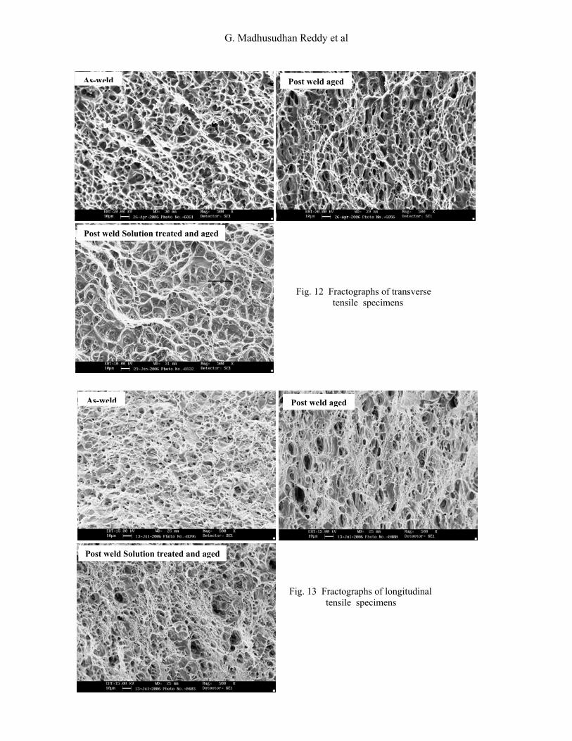
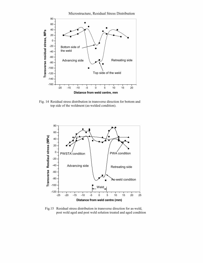
Hardness profile of the post weld heat treated conditions are presented in Fig. 10. Post weld aging treatment increased the hardness at the interface of the joint. As expected, aging of the as-friction stir weld does not alter the grain structure in the nugget region. Aging treatment reduces the dislocation density in the stir region and results in fine precipitates [23]. This fine precipitation more than compensates for any loss in hardness due to reduction in dislocation density and raises the hardness of the nugget region. The peak hardness of PWA weld was close to that in the PWSTA weld. Post weld solution treatment and aging raises hardness homogenously to about 120Hv. The increase in hardness is due to the re-precipitation of the precipitates throughout the weld. Aging does not improve the hardness of the soft HAZ region adjacent to the thermo mechanical zone. This behaviour could be due to coarsening of precipitates. 3.3.2 Tensile tests Transverse orientation: Tensile property data on transverse tensile specimens are presented in Table 3. The strength and ductility in the as-welded condition are lower than the parent metal in T6 condition. Post weld aging did not result in improvement in strength while, post weld STA improved the strength. However, the strength in this condition is lower that the parent metal in the T6 condition. Post weld treatment led to reduction in ductility. The ductility in post weld aged condition is the lowest. PWSTA produced a considerable increase in yield and ultimate tensile strength of the joint compared to as-welded condition. A remarkable decrease of the ductility of the PWSTA weld could be due to a higher concentration of fine hardening Mg2Si particles during aging treatment. Failure in both as-welded and post heat-treated conditions were shear fractures (Fig.11). Shear fractures are typical in rectangular cross sectional test specimens. In the as-welded and PWA conditions failure location was in the HAZ. The fracture position in tensile specimens coincided with minimum hardness position (which is as expected), whereas in PWSTA condition, tensile fracture position on the advancing side of weld zone. This could be attributed to the presence of precipitate free zone beside grain boundaries and coarsening equiaxed grain structures in the weld. The loss of ductility in PWA condition may be a result of the age hardening of the nugget, which results in a high resistance to deformation, and of the over-aged precipitation state in the HAZ, which causes localization of deformation in the later. Fractography of tensile samples revealed that samples failed in ductile mode (Fig.12). Longitudinal orientation: Tensile property data on longitudinal tensile specimens are presented in Table 4. It is observed that strength and ductility of the weld, which constitutes of entirely weld nugget are lower than those of starting parent metal. Low strength could be attributed to dissolution of strengthening precipitates. Post weld aging improved strength at the expense of ductility. Post weld STA restored the strength and ductility to nearly equal to that of the parent metal. Fractography of tensile samples revealed that the samples failed in ductile mode (Fig. 13) 3.4 Residual stresses Residual stress distributions across the friction stir welds in the as-welded condition on top side and root side are presented in Fig.14.The observed residual stress magnitudes are lower than yield strength of the parent metal. Residual stress exhibited an ‘M’ like distribution across the weld. Fig. 14 reveals that maximum tensile stresses were located 7 mm away from the weld centerline. Compressive residual stresses were noticed in the weld region and
Microstructure, Residual Stress Distribution
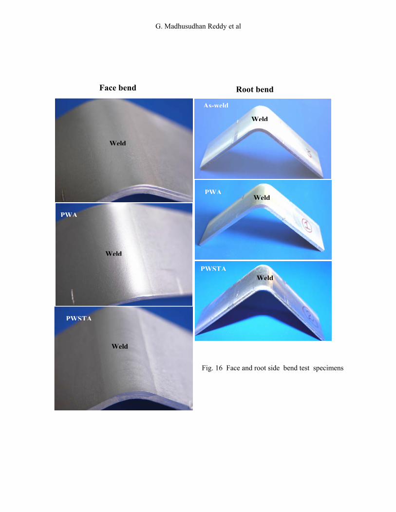
unaffected parent metal. Asymmetry in residual stress profile was observed within the weld zone with stress being higher on the advancing side. This asymmetry is consistent with published literature of higher stresses on the advancing side [24]. Higher residual stress gradient in this region could be related to higher thermal gradients on the advancing side resulting in the observed asymmetry on the measured residual stresses. The distance between the two peaks of residual stress distribution corresponds to the tool shoulder diameter. The width of the ‘M” is low on root side residual stress distribution (Fig. 14) which corresponds to the shape of the tool which is wider at the top because of the shoulder. During friction stir welding heat is assumed to be produced mainly through the friction between the tool shoulder and work piece surface [25]. Therefore heat is no longer concentrated to a narrow zone, but rather generated throughout a broad band having the width of the tool shoulder diameter, Therefore the steep temperatures gradients are not expected to be in the center of the weld, but at the edges of the shoulder. This area is characterized by highest tangential speeds of the tool and, therefore, also by the highest heat production rates. The last regions to contract are, therefore, the ones at a certain distance from the weld center directly under the tool shoulder edge. Two maximum in the residual stress curve in the tensile region are expected at these two points (Fig. 14 ). As outlined in literature [26-27], friction stir weld is obtained by rotational extrusion of material around the tool and pin within a transverse region that is approximately bounded by the shoulder diameter at the crown and the pin diameter at the root, forming what may be called an extrusion zone. Consolidation of the FSW material is achieved within the extrusion zone through downward forces exerted by the tool shoulder. Due to the deformation constraint provided by the relatively cold material along each side of the extrusion zone, heating of the extruded material will result in thermal expansion that cannot be accommodated by the surrounding material. Thus, the extruded material experiences compressive stresses. As the extrusion zone is deforming plastically, the material outside of the extrusion zone remains elastic. Thus after cooling, the elastic material surrounding the extrusion zone will be attempt to return to its initial configuration. Sine plastically deformed material within the extrusion zone will try to retain its permanent deformation, the resulting incompatibility between these two states results in tensile stresses in the HAZ region and compressive zone in the weld zone. Residual stress distribution of the post weld heat treated welds are presented in Fig.15. After post weld aging treatment, the stresses are very localized in the HAZ, which also explains the low elongation in this condition. Residual stress distribution across the weldment after PWSTA treatment is uniform thought the weldment. The average stress is around 45 MPa. Volume difference between matrix and precipitates results in transformation stress/strain. However stress/strain will be relaxed during aging treatment. 3.5 Bend Tests Root and face bend tests were used as an important tool to understand about the ductility and toughness of friction stir welds. As-friction stir weld, PWA and PWSTA weld samples passed 900 bend test (Fig. 16)
G. Madhusudhan Reddy et al
4. Conclusions Friction stir welding of alloy AA 6060-T6 resulted in a dynamically recrystalized zone, TMAZ and HAZ. A softened region has clearly occurred in the friction stir welded joints of the 6061-T6 alloy, due to dissolution of strengthening precipitates. PWSTA results in coarsening of the grains in the weld zone In the as- friction weld and PWA condition tensile failure location is in the HAZ. PWSTA has significant effect on the fracture location of the joint. In this condition tensile fracture location was on advancing side of the weld zone. PWSTA treatment produced a considerable increase in the yield and ultimate tensile strength of the joint. A remarkable decrease of the ductility response after T6 treatment was observed. Hardness profile across the weld was not consistent with grain size observed. This was because the hardness profiles in the age hardnable aluminum alloy depened strongly on the precipitate distribution rather than on the grain size. The tensile strength of the joint is lower than that of the parent metal. The as-weld and post weld heat treated samples did not fail in bend test. The transverse residual stresses exhibit an ‘M’ like curve with maximum lying at a distance corresponding to the edge of the tool shoulder. The stress distribution trends follow similar to hardness distribution trends across the weld Acknowledgement The authors would like to thank Director, Defence Metallurgical Research Laboratory, Hyderabad and Director Defence Research Development Laboratory, Hyderabad for their continued encouragement and permission to publish this work. Financial assistance from Defence Research Development Organization (DRDO) is gratefully acknowledged
References
1. Cam G., Dos Santos J.F., and Kocak M., “Laser and electron beam weldability of Al-alloys:
literature review”, GKSS Report 97/E/25, IIW Document IX-1896-98, GKSS Research Centre, Geesthacht, 1997.
2. Madhusudhan Reddy G., Sammaiah P., Murthy C.V.S., and Mohandas T., “Influence of
welding techniques on microstructure and mechanical properties of AA 6061 (Al-Mg-Si) gas tungsten arc welds”, Proceeding of National Conference on “Processing of Metals”, January 31-Februaruy 01, PSG College of Technology, Coimbature, India, Invited paper No.2, 33-46, 2002
3. Kou S., “Welding metallurgy and weldability of high strength aluminum alloys”, Welding
research Council, Bulletin 320, 1986, Newyork. 4. Thomas W.M., Nicholas E.D., Needham J.C., Murch M.G., Temple-Smith P., and Dawes
C.J., “ Friction stir butt welding”, International Patent Application No. PCT/GB92/02203; GB patent Application No. 9125978.8, 1991; US Patent No. 5460317, 1995.
5. Chen C.M., and Kovacevic R., “Finite element modeling of friction stir welding-thermal and
thermo-mechanical analysis”, Machine Tools & Manufacture, 43, 1319-1326, 2003.
Microstructure, Residual Stress Distribution
6. Song M., Kovacevic R., “Thermal modeling of friction stir welding in a moving coordinate and its validation”, International Journal of Machine Tool and Manufacturing , 43(6), 605-615, 2003.
7. Ying Li., Murr L.E., and McClure J.C., “Flow visualization and residual microstructure
associated with the friction-stir welding of 2024 aluminum to 6061 aluminum”, Materials Science and Engineering A , A271, 213-223, 1999.
8. Fonda R.W., Bingert J,F., Colligan K.J., “Development of grain structure during friction stir
welding”, Scripta Materialia, 51, 243-248, 2004.
9. Su J.Q., Nelson T.W., Mishra R., Mahoney M., “Microstructural investigation of friction stir welded 7050-T651 aluminum”, Acta Materialia, 51 (3), 713-729, 2003.
10. Peel M., Steuwer A., Preuss M., Withers P.J., “Microstructure, mechanical properties and
residual stresses as a function of welding speed in AA 5083 friction stir welds, 51(160, 4791-4801, 2003.
11. James M.R., and Cohen J.B., “ The measurement of residual stresses by X-ray diffraction
technique”, Treatise on Materials Science and Technology, H. Herman (ed.), Academic Press, NY, 19A, 1-62, 1980.
12. Liu G., Murr L.E., Niou C.S., McClure J.C., and Vega F.R., “Microstructural aspects of the
friction–stir welding of 6061-T6 aluminium’, Scripta Materialia, 37 (3), 355-361, 1997.
13. Huijie Liu, Fujii H., Maeda M., and Nogi, “Tensile properties and fracture locations of friction--stir welded joints of 6061-T6 aluminum alloy”, Journal of Materials Science Letters, 22, 1061-1063, 2003
14. Lee W.B., Yeon Y.M., and Jung S.B., “Evaluation of the microstructure and mechanical
properties of friction stir welded 6005 aluminium alloy, Materials Science and Technology, 19, 1513-1518, November 2003.
15. Somasekharan A.C and Murr L.E., “Microstructures in friction-stir welded dissimilar
magnesium alloys and magnesium alloys to 6061-T6 aluminum alloy”, Materials Characterization, 52, 49-64, 2004.
16. Hatch J.E., “Aluminum: Properties and Physical Metallurgy”, Aluminum Association, Inc.,
Published by ASM, Materials Park, Ohio, 1984.
17. Krishnan K.N., “ The effect of post weld heat treatment on the properties of 6061 friction stir welded joints”, Journal of Materials Science, 37, 473-480, 2002.
18. Charit I., Mishra R.S., Mahoney M.W., Scripta Materialia, 47, 631-636, 2002
19. Feng J.C., Chen Y.C., and Liu H.J., “Effects of post-weld heat treatment on microstructure
and mechanical properties of friction welded joints of 2219-O aluminum alloy”, Materials Science and Technology, 22(1), 86-90, 2006.
20. Mahoney M.W., Rhodes C.G., Flintoff J.G., Spurling R.A., and Bingel W.H., “Properties of
friction-stir welded 7075 T651 aluminum”, Metallurgical and Materials Transactions A, 29A, 1955-1964, July 1998.
G. Madhusudhan Reddy et al
21. Rhodes C.G., Mahoney M.W., Bingel W.H., Spurling R.A., and Bampton C.C., “ Effects of friction stir welding on microstructure of 7075 aluminum”, Scripta Materialia, 36(1), 69-75, 1997.
22. Mondolfo L.F., Aluminum Alloys: Structure and Properties, Butterworths, 644-651, 1976 23. Yutaka S., Sato, Hiroyuki Kokawa, Masatoshi Enomoto, Shigetoshi Jogan, and Takenori
Hashimoto, “Precipitation sequence in friction stir weld of 6063 aluminum during aging”, Metallurgical and Materials Transactions A, 30A, 3125-3130, December 1999.
24. Lima E.B.F., Wegener J., Dalle Donne C., Goerigk G., Wroblewski T., Buslaps T., Pyzalla
A.R., and Reimers W., “Dependence of the microstructure, residual stresses and texture of AA 6013 friction stir welds on the welding process”, Z. Metallkd, 94, 908-915, 2003.
25. Gould J.E., Lienert T.J., Feng Z., SAE Trans., Journal of Materials & Manufacturing, 107,
1093-1099, 1998.
26. Xu S., Deng X., Reynolds A.P., and Seidel T.U., “ Finite element simulation of material flow in friction stir welding”, Science and Technology of Welding and Joining”, 6(3), 191-193, 2001.
27. Liming K.E., Xing L.I., and Indacochea J.E., “Material flow patterns and cavity model in
friction-stir welding of aluminum alloys”, Metallurgical and Materials Transactions B, 35B, 153-160, February 2004.
Table 1 Chemical composition and mechanical properties of AA 6061-T6 aluminium alloy
Chemical composition (wt%)
Mechanical properties
0.2% Yield strength (MPa) Ultimate tensile strength (MPa) Elongation (%)
275 310 12
Table 2 Tool size and welding parameters used in experiments
Tool Size Welding parameters
Shoulder diameter (mm)
Pin diameter (mm)
Pin length (mm)
Rotation speed, (rev min-1)
Travel speed (mm min-1)
10 5 6.4 800 15
Si Fe Cu Mn Mg Cr Zn
0.66 0.25 0.31 0.08 0.99 0.16 0.01
Microstructure, Residual Stress Distribution
Table 3 Room tensile properties in transverse orientation of friction stir welded AA 6061 aluminum alloy
Condition Yield strength (Mpa)
Ultimate strength
(MP)
Elongation (%)
Failure location
Base metal T6 275 310 12 As-friction-stir welded 125 192 9 HAZ
Post weld aged condition 120 176 3 HAZ Post weld solution treated
and aged condition 256 272 Weld on
advancing side
Table 4 Room tensile properties in longitudinal orientation of friction stir welded AA 6061 aluminum alloy
Condition 0.2% Yield strength (MPa)
Ultimate tensile strength (MPa)
Elongation (%)
Base metal T6 275 310 12
As-friction-stir welded 105 155 8.5
Post weld aged condition 235 270 5
Post weld solution treated and aged condition
240 295 10
G. Madhusudhan Reddy et al
Fig. 1. Illustration of the friction-stir welding process
Microstructure, Residual Stress Distribution
TOOL SHOULDER
THREADED TOOL PIN
Fig. 2 Friction-stir welding tool geometry
Fig. 3 X -ray residual stress analyzer
G. Madhusudhan Reddy et al
ADVANCING SIDE
RETREATING SIDE Weld
Top view Bottom view Weld
Fig. 4 Top and bottom view of a typical joint along with X-ray radiography of the joint
Fig.5 Typical microstructure of the as-welded sample cross section perpendicular to the welding direction
Retreating side
Nugget zone
Advancing side
TMAZ HAZ
Parent metal
Fig.6 Microstructure of the as-welded sample showing recrystalized grains
20 µm
Microstructure, Residual Stress Distribution
Location Mg Si Mn Fe Al
Region ‘A’ 3.29 1.12 0.34 0.75 balance
Region ‘B’ 1.2 0.29 0.21 0.14 balance
200 µm
100 µm
A A A
B
B
Electron probe micro analysis of regions A and B (Wt %)
Fig. 7 Optical image of the banded microstructure and chemical analysis of the banded region in the horizontal cross section of friction stir weld
G. Madhusudhan Reddy et al
Fig. 9 Microstructure of friction stir weld (a) Post weld aged condition
(b) Post weld solution treated and aged condition
200 µm
b
20 µm
a
Fig. 8 Optical macrostructure of cross section Friction welded samples (a) Post weld aged condition (b) Post weld solution treated and aged condition
a
1mm
b
Microstructure, Residual Stress Distribution
-25 -20 -15 -10 -5 0 5 10 15 20 2540
50
60
70
80
90
100
110
120
130
140
150
Har
dnes
s (H
v)
Distance form weld centre (mm)
As-weld
PWA condition
PWSTA condition
Weld
Advancing sideRetreating side
Weld
PWA
Weld
PWSTA
Weld
As-weld
Fig.11 Cross section of a fracture surface of tensile test sample (arrow indicates fracture surface)
Fig. 10 Hardness traverses across friction-stir welds
G. Madhusudhan Reddy et al
Fig. 12 Fractographs of transverse tensile specimens
As-weld Post weld aged
Post weld Solution treated and aged
As-weld Post weld aged
Post weld Solution treated and aged
Fig. 13 Fractographs of longitudinal tensile specimens
Microstructure, Residual Stress Distribution
-20 -15 -10 -5 0 5 10 15 20-160
-140
-120
-100
-80
-60
-40
-20
0
20
40
60
80
Bottom side of the weld
Tran
sver
se re
sidu
al s
tres
s, M
Pa
Distance from weld centre, mm
Top side of the weld
Advancing side Retreating side
Fig. 14 Residual stress distribution in transverse direction for bottom and top side of the weldment (as-welded condition).
-25 -20 -15 -10 -5 0 5 10 15 20 25-120
-100
-80
-60
-40
-20
0
20
40
60
80
Tran
sver
se R
esdi
aul s
tres
s (M
Pa)
Distance from weld centre (mm)
As-weld condition
PWA conditionPWSTA condition
Weld
Advancing side Retreating side
Fig.15 Residual stress distribution in transverse direction for as-weld, post weld aged and post weld solution treated and aged condition
G. Madhusudhan Reddy et al
As-weld
Fig. 16 Face and root side bend test specimens
Weld
Face bend Root bend
Weld
As-weld
Weld
PWSTA
WeldPWSTA
PWA
Weld
WeldPWA


![Prediction of welding residual stresses using machine ... · characterise the distribution of residual stresses in structural welds [6, 7]. With the development of residual stress](https://img.pdfslide.net/doc/110x75/5fa3f63f3be93a3412525cc3/prediction-of-welding-residual-stresses-using-machine-characterise-the-distribution.jpg)


![[Prof] Determination of Residual Stresses by X-Ray Diffraction](https://img.pdfslide.net/doc/110x75/55cf9a54550346d033a13e5d/prof-determination-of-residual-stresses-by-x-ray-diffraction.jpg)