Embed Size (px)
Citation preview
Page 1 Specifications subject to change without notice
MicroVue and MicroVue Commander User Manual
Users’ Manual
Version 1.7 8 April 2010
Cobham Surveillance
Domo Products 11 Manor Court, Barnes Wallis Road, Segensworth,
Hampshire, PO15 5TH, England
T: +44 (0)1489 566 750 F: +44 (0)1489 880 538
2
1 Table of Contents
1 Table of Contents .......................................................................................... 2
2 List of Figures ................................................................................................ 3
3 List of Tables ................................................................................................. 3
4 Change History .............................................................................................. 4
5 About this Manual .......................................................................................... 5
6 Introduction.................................................................................................... 6
7 Warranty and Support ................................................................................... 8
7.1 Warranty Cover ............................................................................................... 8
8 Safety.............................................................................................................. 9
8.1 Safe Operating Procedures ............................................................................. 9
8.2 EMC Approvals ................................................................................................ 9
9 Getting Started and Basic Operation ......................................................... 10
9.1 Which Model do I have? ................................................................................ 10
9.2 Basic operation .............................................................................................. 14
10 Advanced Operation .................................................................................... 24
10.1 Advanced Functions of the Touch Screen Controller .................................. 25
10.2 Advanced Functions of the ClearCam Control Page ................................... 28
10.3 Using the External Antenna Function. ........................................................ 29
10.4 Using the Monitor Input Function. ............................................................... 30
10.5 Controlling Other domo Devices from the MicroVue. .................................. 30
10.6 Using the optional NDT Recorder. .............................................................. 31
10.7 Using the optional micro-video discrete viewer. .......................................... 32
10.8 Connecting the PC Controller ..................................................................... 32
10.9 Upgrading the MicroVue Receiver Software ............................................... 39
10.10 Upgrading the MicroVue Control Software .................................................. 41
11 Fault Finding ................................................................................................ 47
11.1 MicroVue .................................................................................................... 47
11.2 Touch screen .............................................................................................. 47
11.3 RF and Audio / Video ................................................................................. 48
11.4 Commander link ......................................................................................... 49
12 Connector Pin Outs ..................................................................................... 50
12.1 Power: 4-pin 1B LEMO Socket ................................................................... 50
12.2 RS232 PC Control: 3-pin 0B LEMO Socket ................................................ 50
12.3 RS232 External Control: 3-pin 0B LEMO Socket ........................................ 50
12.4 Chaining: 6-pin 0B LEMO Socket ............................................................... 50
12.5 RS232 Data - 3-pin 0B LEMO Socket ......................................................... 51
12.6 Umbilical Video and PTZ - 7-pin Mini DIN ................................................... 51
13 Control Protocols ........................................................................................ 52
13.1 RS232 Control – General Principles ........................................................... 52
13.2 Packet Structure Sending (from PC) ........................................................... 52
13.3 Packet Structure Reply (from controlled device) ......................................... 53
13.4 Receiver Command List ............................................................................. 54
14 Default Configurations ................................................................................ 57
3
2 List of Figures
Figure 1 Front view of the MicroVue lid ......................................................... 12
Figure 2 Top view of the MicroVue base ....................................................... 12
Figure 3 Rear view of MicroVue with external connector cabinet ................ 13
Figure 4 Top view of the MicroVue Commander base (no DVR) ................. 13
Figure 5 Lid of the domo MicroVue with LCD and OSD function ................ 16
Figure 6 The MicroVue ‘Main status screen’ ................................................. 17
Figure 7 Commander PTZ camera control panel ......................................... 19
Figure 8 Received video with OSD on Channel A ........................................ 21
Figure 9 The MicroVue principle screens ...................................................... 25
Figure 10 ClearCam status and control page ................................................ 28
Figure 11 Receiver PC control application ..................................................... 34
Figure 12 Back panel connectors. ................................................................. 39
Figure 12 Tera Term New Connection. .......................................................... 40
Figure 13 Tera Term serial port setup detail. ................................................ 40
Figure 14 Tera Term send file detail. .............................................................. 41
Figure 15 Back panel connectors. ................................................................. 42
Figure 16 Tera Term New Connection. ......................................................... 42
Figure 17 TeraTerm Serial Port Set-up Details .............................................. 43
Figure 18 D586 bootloader initialisation ......................................................... 43
Figure 19 D586 bootloader communication ................................................... 44
Figure 20 D586 bootloader communication showing erase procedure ........ 44
Figure 21 TeraTerm Send File Details ........................................................... 45
Figure 22 TeraTerm showing downloading code to D586 ............................ 45
Figure 23 D586 bootloader communication showing Programming Flash .. 46
3 List of Tables
Table 1 MicroVue product codes .................................................................... 10
Table 2 MicroVue Commander product codes .............................................. 11
Table 3 LED colour codes ............................................................................... 15
Table 4 Main status screen ............................................................................. 17
Table 5 MicroVue Commander switch panel functions ................................. 19
Table 6 Receiver menu structure ................................................................... 26
Table 7 ClearCam status screen .................................................................... 28
Table 8 ClearCam sleep modes ..................................................................... 29
Table 9 Transmitter menu structure ............................................................... 30
4
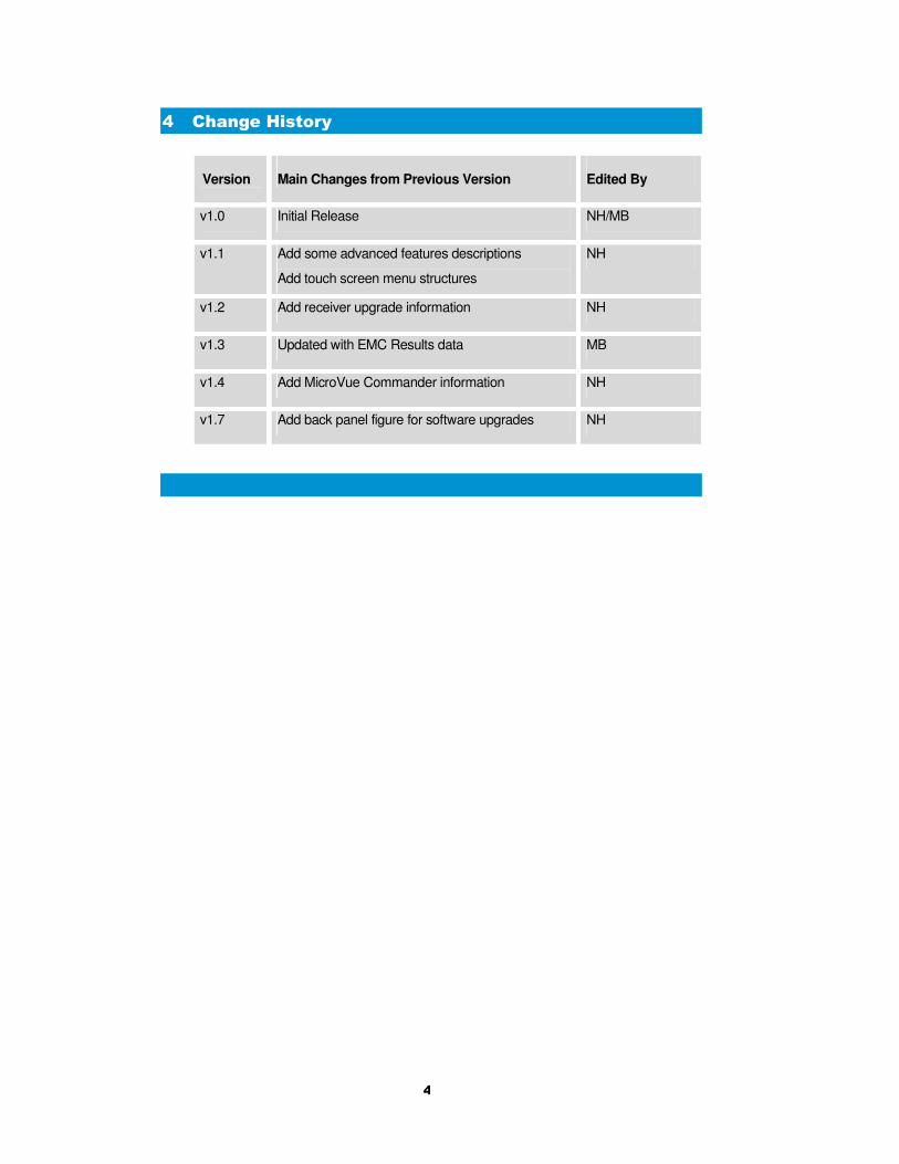
4 Change History
Version
Main Changes from Previous Version
Edited By
v1.0 Initial Release NH/MB
v1.1 Add some advanced features descriptions
Add touch screen menu structures
NH
v1.2 Add receiver upgrade information NH
v1.3 Updated with EMC Results data MB
v1.4 Add MicroVue Commander information NH
v1.7 Add back panel figure for software upgrades NH
5
5 About this Manual
This manual describes the operation of the domo MicroVue. The
manual is divided into three main sections.
• Getting started and basic operation
This section describes to users how to deploy and use a domo
MicroVue unit.
• Advanced operation
This section describes the operation of the system in more detail,
concentrating particularly on advanced use of the touch screen
controller, use the optional recorder and umbilical micro-viewer options.
• Technical reference
This section provides technical specification and control protocol data
and will be of interest to those integrating the MicroVue into larger
systems.
6
6 Introduction
The domo MicroVue is a tactical digital video receiver and is part of the
domo SOLO4 and SOLO2 product family. The SOLO4 and SOLO2
product range enables the user to build wireless digital microwave video
systems. The domo SOLO4 and SOLO2 products have been designed
to provide rugged point-to-point links for high quality full frame rate
video, and audio, even in non line of sight and urban environments.
Existing analogue systems suffer from impairments such as video noise,
loss of colour information and poor image quality when line of sight
cannot be maintained, and solutions based on wireless internet
standards and PC platforms deliver poor quality video.
The domo SOLO4 and SOLO2 system is a digital system that uses the
COFDM modulation technique, which effectively eliminates the
problems caused by multipath and reflections.
The SOLO product range allows law enforcement, surveillance and
emergency service communities to now receive the highest quality
video images, in real time, direct from personnel, buildings and vehicles.
The domo SOLO2 system employs the DVB-T 2K carrier COFDM
technology.
The domo SOLO4 system employs a revolutionary narrow band
2.5MHz COFDM technology which demonstrates better propagation for
longer range links, and extra bandwidth efficiency. The domo SOLO4
system can also be upgraded to include a 1.2MHz COFDM modulation
and MPEG4 compression for excellent range performance.
The MicroVue is a brieface receiver / recorder package for tactical video
surveillance operations. Additionally, the MicroVue can be used as a
remote video receiver for UAV and UGV applications. The MicroVue
combines a domo SOLO Receiver with two diversity down converters
and two antennas into one rapidly deployable briefcase kit.
The MicroVue Commander is a basic MicroVue brieface receiver with
added PTZ camera control and Telemetry transmitter. This is used in
conjunction with the ClearCam deployable periscope camera to provide
a complete rapid deployment surveillance link.
A 8.4’’ colour LCD screen is mounted in the lid. The MicroVue is
supplied with comprehensive touch screen control panel for control and
setup. The MicroVue is supplied with AC, DC and internal battery
power. For unusual installations the internal antennas and down
converters can be bypassed and external antennas and down
converters fitted.
As standard the domo MicroVue is supplied without a recorder, but can
optionally be fitted with the NDT200 recorder, other recorders are
available on request. An optional MicroViewing screen connected by
umbilical is also available as an option.
The domo narrow bandwidth modulation offers unprecedented
spectrum efficiency, while also increasing the system sensitivity and
therefore range.
7
The MicroVue has comprehensive On Screen Display diagnostic
capability to show link quality and spectrum and is equipped with video,
two voice and data channels. Security of transmission is ensured by the
use of Standard ABS encryption or for greater security the optional
AES128- or 256-bit encryption algorithms.
Features:
• Comprehensive Demodulation 8 / 7 / 6 / 2.5 and 1.25MHz
(optional)
• Maximum Ratio Combining antenna diversity for fade and
multipath elimination.
• Lid mounted antennas.
• 8.4’’ colour monitor in lid.
• AC, DC, internal battery operation.
• Batteries recharged internally.
• Recorder playback on lid monitor.
• Comprehensive On Screen Display (OSD) diagnostics for link
analysis, including spectrum analyser.
• 5.5” touch screen in base for device configuration.
• Headphone output.
• Internal AES 128 or 256 encryption.
• Optional NDT Recorder with playback to lid mounted monitor.
• Optional discrete micro-video viewer on umbilical.
• Commander: PTZ camera control
IMPORTANT NOTE
The SOLO4 MicroVue has been specifically designed for government security and law
enforcement users, the equipment will tune across frequencies that are only available to
licensed government users. Non-government users should employ the equipment
restricted to the license exempt bands only typically 1.389 to 1.399GHz and 2.400 to
2.483GHz.
8
7 Warranty and Support
7.1 Warranty Cover
domo offers a 12 month standard product warranty. During this period,
should the customer encounter a fault with the equipment we
recommend the following course of action:
• Check the support section of the website for information on that product and any software/firmware upgrades. If fault persists;
• Call our support line and report the fault. If fault persists and you are informed to return the product please obtain an RMA number from the domo support department, and ship the equipment with the RMA number displayed and a description of the fault. Please email the support section the airway bill/consignment number for tracking purposes.
• If you have extended warranty provisions then domo will send an immediate advance replacement to you. Under most circumstances this must be returned once the fault item is repaired.
Depending on the nature of the fault domo endeavor to repair the
equipment and return it to the customer within 14 days of the item
arriving at our workshops.
Obviously it is impossible to cater for all types of faults and to manage
100% replacement part availability, and delays are sometimes
inevitable. This is why domo recommend that its customers take out an
extended warranty (which includes advanced replacement of faulty
items), and/or hold a basic level of spare parts, which can be held by
domo on the customer’s behalf.
Please contact domo for details of packages that can be tailored to meet
your individual needs, whether they are service availability, technical
training, local geographic support or dedicated spares holdings.

9
8 Safety
8.1 Safe Operating Procedures
• Ensure that the power supply arrangements are adequate to meet the stated requirements of the product.
• Caution: When using the DC input ensure the DC supply is capable of 12V at 8A.
• Caution: The MicroVue is not provided with a mains ON / OFF switch, so when operating on mains supply, ensure that the mains supply socket is easily accessible to the user.
• Caution: Risk of explosion if battery is replaced by an inappropriate type. Battery replacement can only be undertaken by domo personnel who will also ensure safe battery disposal.
• Operate within the environmental limits specified for the product.
• Do not subject the indoor equipment to splashing or dripping liquids.
• Only authorized, trained personnel should open the product. There are no functions that required the User to gain access to the interior of the product.
• The unit is designed only to be operated with the Lid open and front storage pouch removed, to ensure adequate airflow.
• The MicroVue with the lid up, should not be exposed to prolonged rain fall, this will cause damage.
8.2 EMC Approvals
Tested in accordance to EN60950-1:2001

10
9 Getting Started and Basic Operation
9.1 Which Model do I have?
Each unit in the domo SOLO4 and SOLO2 product range is marked
with two panels. These panels can be found below the cable bag in the
base of the unit.
• Product Code Panel. Give product code and manufacturers
information.
• CE and Serial Number Panel. Gives CE mark and product
serial number.
The domo product code can be referenced in the table below.
Table 1 MicroVue product codes
Product Code Product Accompanying items
SOL4MIV-034047 MicroVue Tactical
Receiver
340 to 470MHz
Cables:
Control Cable (3 way lemo to 9
way DType) 3m
External Control (3way Lemo
to 3 way lemo) 3m
Audio Cable (phono)
Video Cable (BNC)
DC Power 2m
CD with operating software
and manual
SOL4MIV-057067 MicroVue Tactical
Receiver
575 to 675MHz
As above
SOL4MIV-115140 MicroVue Tactical
Receiver
1.15 to 1.4GHz
As above
SOL4MIV-228255 MicroVue Tactical
Receiver
2.28 to 2.55GHz
As above
MICROVDVR Compact HDD DVR
Recorder Option
None Required
domo SOL4MIV-228255 S-Band
Made in the UK
11
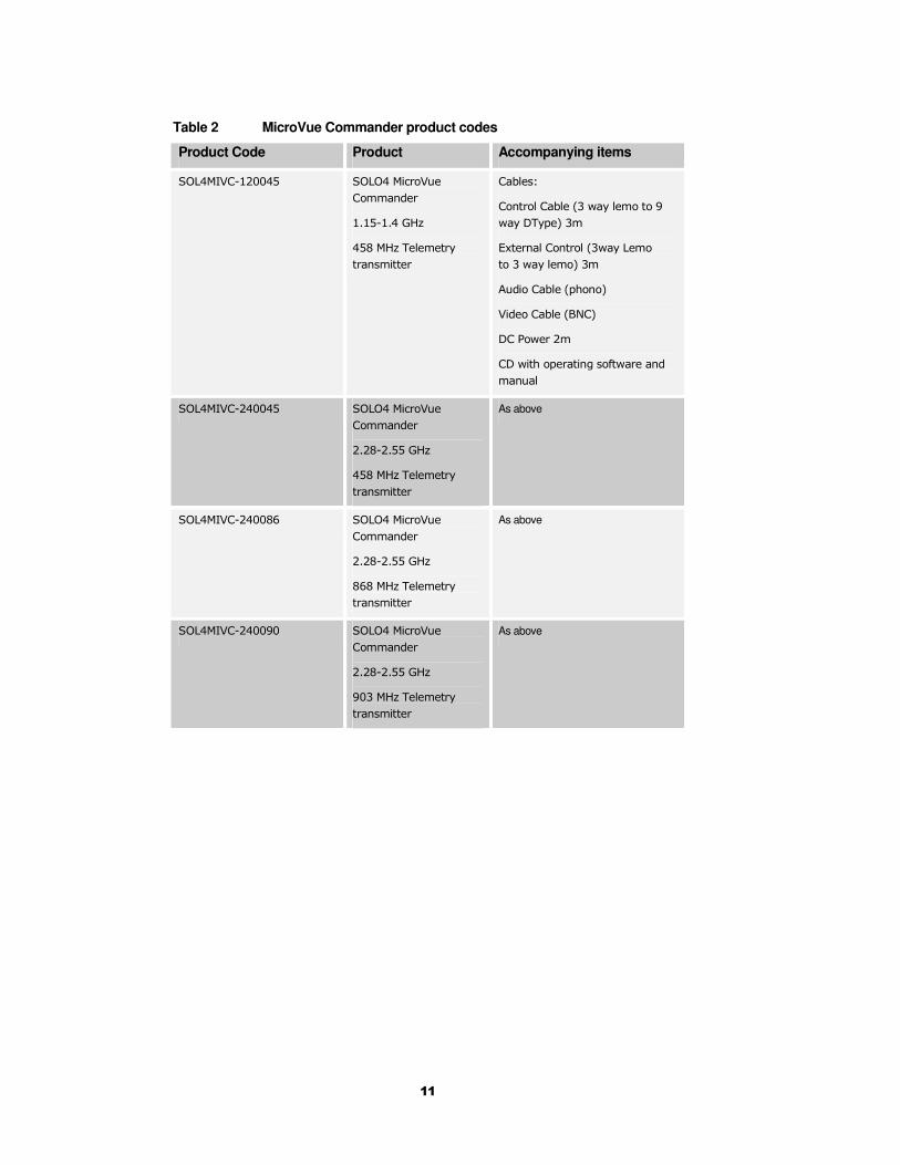
Table 2 MicroVue Commander product codes
Product Code Product Accompanying items
SOL4MIVC-120045 SOLO4 MicroVue
Commander
1.15-1.4 GHz
458 MHz Telemetry
transmitter
Cables:
Control Cable (3 way lemo to 9
way DType) 3m
External Control (3way Lemo
to 3 way lemo) 3m
Audio Cable (phono)
Video Cable (BNC)
DC Power 2m
CD with operating software and
manual
SOL4MIVC-240045 SOLO4 MicroVue
Commander
2.28-2.55 GHz
458 MHz Telemetry
transmitter
As above
SOL4MIVC-240086 SOLO4 MicroVue
Commander
2.28-2.55 GHz
868 MHz Telemetry
transmitter
As above
SOL4MIVC-240090 SOLO4 MicroVue
Commander
2.28-2.55 GHz
903 MHz Telemetry
transmitter
As above
12
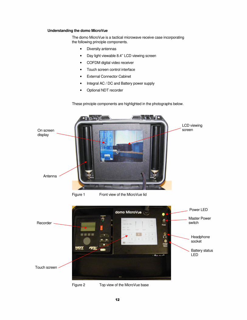
Understanding the domo MicroVue
The domo MicroVue is a tactical microwave receive case incorporating
the following principle components.
• Diversity antennas
• Day light viewable 8.4’’ LCD viewing screen
• COFDM digital video receiver
• Touch screen control interface
• External Connector Cabinet
• Integral AC / DC and Battery power supply
• Optional NDT recorder
These principle components are highlighted in the photographs below.
Figure 1 Front view of the MicroVue lid
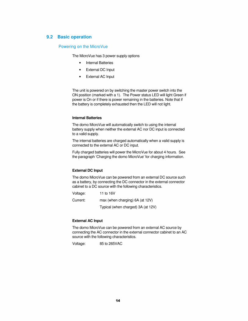
Figure 2 Top view of the MicroVue base
Antenna
On screen display
LCD viewing screen
Power LED
Battery status LED
Headphone socket
Master Power switch
Touch screen
Recorder

13
Figure 3 Rear view of MicroVue with external connector cabinet
The MicroVue Commander includes all of the basic MicroVue
functionality, with the addition of
• a PTZ control panel in the base of the unit, used for controlling the remote periscope camera
• a telemetry transmitter and antenna in the lid, used for sending the camera control commands.
Figure 4 Top view of the MicroVue Commander base (no DVR)
PC Control Connector for MicroVue
Connector to control external domo devices
Audio in
Audio out
External Viewer / PTZ connector
Down-converter inputs
Video in Video out
Chaining
Data
DC power input
AC power input
PTZ control panel
14
9.2 Basic operation
Powering on the MicroVue
The MicroVue has 3 power supply options
• Internal Batteries
• External DC Input
• External AC Input
The unit is powered on by switching the master power switch into the
ON position (marked with a 1). The Power status LED will light Green if
power is On or if there is power remaining in the batteries. Note that if
the battery is completely exhausted then the LED will not light.
Internal Batteries
The domo MicroVue will automatically switch to using the internal
battery supply when neither the external AC nor DC input is connected
to a valid supply.
The internal batteries are charged automatically when a valid supply is
connected to the external AC or DC input.
Fully charged batteries will power the MicroVue for about 4 hours. See
the paragraph ‘Charging the domo MicroVue’ for charging information.
External DC Input
The domo MicroVue can be powered from an external DC source such
as a battery, by connecting the DC connector in the external connector
cabinet to a DC source with the following characteristics.
Voltage: 11 to 16V
Current: max (when charging) 6A (at 12V)
Typical (when charged) 3A (at 12V)
External AC Input
The domo MicroVue can be powered from an external AC source by
connecting the AC connector in the external connector cabinet to an AC
source with the following characteristics.
Voltage: 85 to 265VAC
15
Status LEDs
The status LED’s indicate the battery and power status, as outlined in
the table below.
Table 3 LED colour codes
LED Meaning
Power = green The unit is running.
Power = off The unit is switched off or the battery is completely
exhausted.
Power = flashing
green
The batteries are flat and the unit will shut down
shortly.
Battery status =
solid green The batteries are fully charged.
Battery Status =
red
The batteries are being fast charged by an external
source.
Battery Status =
orange Batteries are being preconditioned before fast charge.
Charging the domo MicroVue
The domo MicroVue internal batteries are automatically charged when
the MicroVue is connected to an external AC or DC source.
The time required to fully charge the batteries from fully flat is as follows.
Charging when MicroVue powered off: Approximately 1.5 hours
Charging when MicroVue powered on: Approximately 3 hours
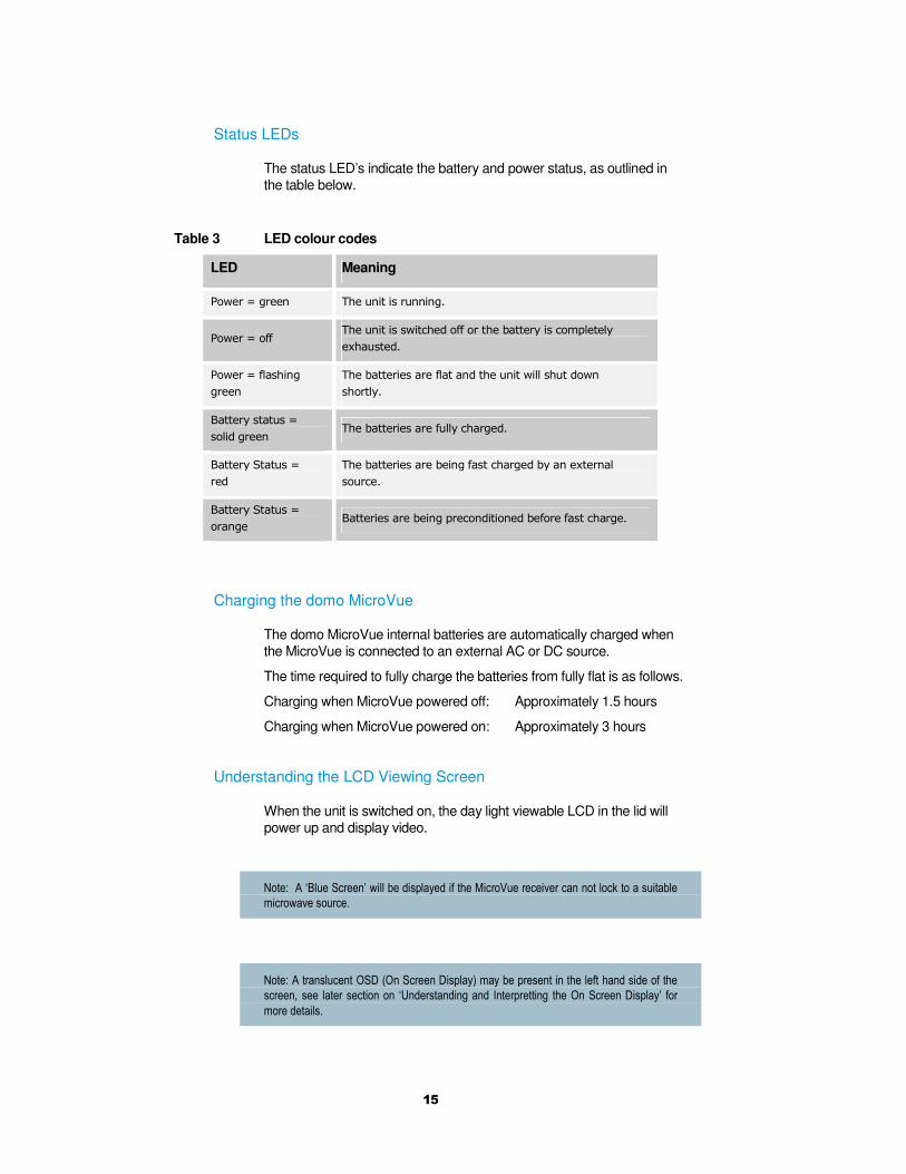
Understanding the LCD Viewing Screen
When the unit is switched on, the day light viewable LCD in the lid will
power up and display video.
Note: A ‘Blue Screen’ will be displayed if the MicroVue receiver can not lock to a suitable
microwave source.
Note: A translucent OSD (On Screen Display) may be present in the left hand side of the
screen, see later section on ‘Understanding and Interpretting the On Screen Display’ for
more details.
16
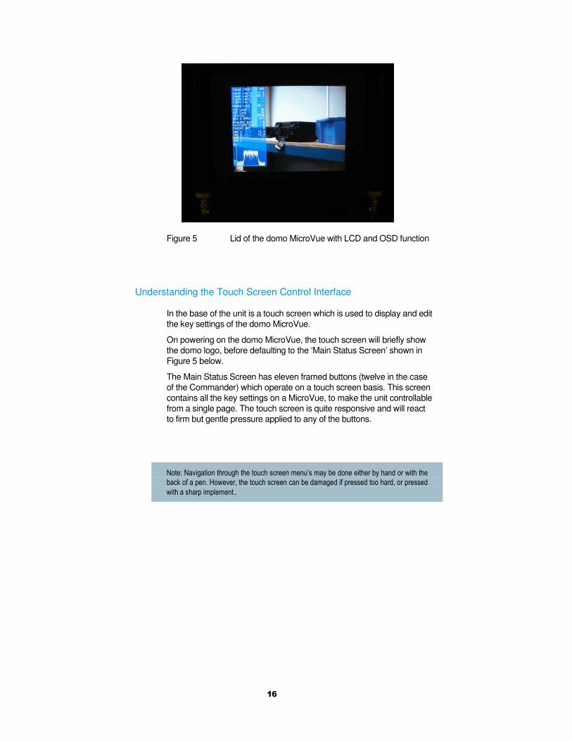
Figure 5 Lid of the domo MicroVue with LCD and OSD function
Understanding the Touch Screen Control Interface
In the base of the unit is a touch screen which is used to display and edit
the key settings of the domo MicroVue.
On powering on the domo MicroVue, the touch screen will briefly show
the domo logo, before defaulting to the ‘Main Status Screen’ shown in
Figure 5 below.
The Main Status Screen has eleven framed buttons (twelve in the case
of the Commander) which operate on a touch screen basis. This screen
contains all the key settings on a MicroVue, to make the unit controllable
from a single page. The touch screen is quite responsive and will react
to firm but gentle pressure applied to any of the buttons.
Note: Navigation through the touch screen menu’s may be done either by hand or with the
back of a pen. However, the touch screen can be damaged if pressed too hard, or pressed
with a sharp implement..
17
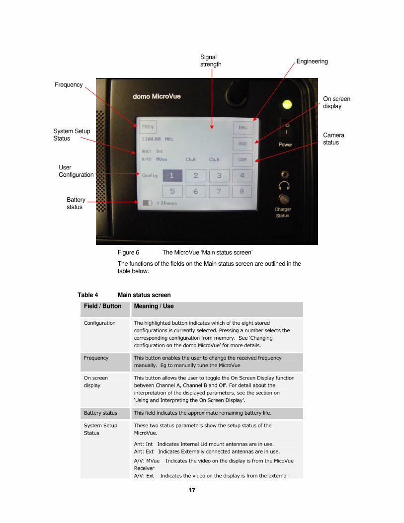
Figure 6 The MicroVue ‘Main status screen’
The functions of the fields on the Main status screen are outlined in the
table below.
Table 4 Main status screen
Field / Button Meaning / Use
Configuration The highlighted button indicates which of the eight stored
configurations is currently selected. Pressing a number selects the
corresponding configuration from memory. See ‘Changing
configuration on the domo MicroVue’ for more details.
Frequency This button enables the user to change the received frequency
manually. Eg to manually tune the MicroVue
On screen
display
This button allows the user to toggle the On Screen Display function
between Channel A, Channel B and Off. For detail about the
interpretation of the displayed parameters, see the section on
‘Using and Interpreting the On Screen Display’.
Battery status This field indicates the approximate remaining battery life.
System Setup
Status
These two status parameters show the setup status of the
MicroVue.
Ant: Int Indicates Internal Lid mount antennas are in use.
Ant: Ext Indicates Externally connected antennas are in use.
A/V: MVue Indicates the video on the display is from the MicoVue
Receiver
A/V: Ext Indicates the video on the display is from the external
User Configuration
Frequency
System Setup Status
Signal strength Engineering
On screen display
Battery status
Camera status
18
input
Engineering This button takes the user to the unit’s comprehensive setup
menu’s. See the ‘Advanced Operation’ section for further details.
Camera status (Commander only) This button accesses the camera status page.
See Figure 10 and Table 7.
Changing Configuration on the domo MicroVue
To simplify the operation of the domo MicroVue, users can pre-program
eight ‘User Configurations’. In their simplest form these can be thought
of in the traditional sense as eight frequency channels. However, the
User Configurations actually store all the parameters of the MicroVue
and not just its frequency.
The default User Configurations with which the unit is shipped are
described in the ‘Default Configurations’ section at the end of the user
guide.
Typically, each User Configuration is pre-programmed with a different
receive frequency. The user can then select the required frequency by
pressing one of the appropriate ‘Config’ buttons on the main touch
screen, labeled 1 to 8.
The currently loaded User Configuration is shown in black inverse text
on the main screen. In the case of Figure 5, this will be config 2.
See the advanced section of the user guide for more information on how
to edit the parameters inside the user configurations.
Tuning the domo MicroVue manually
Pressing the ‘Frequency’ button allows the user to manually tune the
received frequency of the domo MicroVue.
Users can select an appropriate frequency by pressing on the numbers
in the numeric key pad. Frequency must be entered in MHz.
Errors can be deleted using the ‘Clear’ button.
When the correct frequency is keyed in, it can be applied by pressing
the ‘Enter’ key.
The ‘Back’ key returns the user to the ‘Main Status Screen’ without
saving any changes.
Deploying and Operating the domo MicroVue
The domo MicroVue is a tactical digital video receiver, and the following
guidelines should be employed when using the equipment.
• The MicroVue should be operated with the lid up and the
internal antennas vertical for best performance.
• The Telemetry transmit antenna should be attached to the
outside of the MicroVue Commander lid (Commander
only).
19
• The front storage pouch should be removed when the unit is
switched on, to prevent obstruction of the fan.
• An open unit with the lid up should not be exposed to prolonged
rain fall, as this will cause damage.
• Depending on the RF environment (line of sight or non line of
sight) and the power of the transmitter (100mW or 1W), the
MicroVue will operate at a range typically 300m to 1km from the
target transmitter.
• If the MicroVue is being operated inside a building or vehicle,
better results may be achieved by using the external antenna
function and deploying the antennas to the outside of the
building or vehicle.
• To prevent damage to the MicroVue, it should not be operated
too close (within 5m typically, further if the transmitter is greater
than 1W in power) of the transmitter.
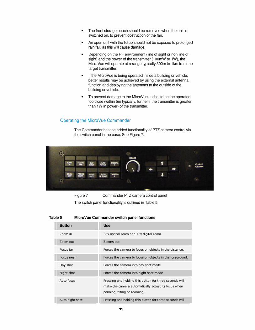
Operating the MicroVue Commander
The Commander has the added functionality of PTZ camera control via
the switch panel in the base. See Figure 7.
Figure 7 Commander PTZ camera control panel
The switch panel functionality is outlined in Table 5.
Table 5 MicroVue Commander switch panel functions
Button Use
Zoom in 36x optical zoom and 12x digital zoom.
Zoom out Zooms out
Focus far Forces the camera to focus on objects in the distance.
Focus near Forces the camera to focus on objects in the foreground.
Day shot Forces the camera into day shot mode
Night shot Forces the camera into night shot mode
Auto focus Pressing and holding this button for three seconds will
make the camera automatically adjust its focus when
panning, tilting or zooming.
Auto night shot Pressing and holding this button for three seconds will

20
make the camera automatically switch to night shot
mode when light levels fall.
Camera 1 Selects video from camera input 1 on ClearCam.
Camera 2 Selects video from camera input 2 on ClearCam.
Speed Sets the speed at which the unit pans and tilts. Note: If
the speed is turned to zero, no panning or tilting will
result.
Pan (left-right) arrows Moves camera through 400° panning range .
Tilt (up-down) arrows Moves camera through +20° to -40° tilt range.
Control address Hex switch to select a specific ClearCam to control (see
paragraph below).
As shown in Figure 7, the Commander base panel contains a
CONTROL ADDRESS rotary hex switch.
This potentially gives the user the ability to control up to 15 remote
ClearCam units from one MicroVue.
To do so, the Channel number of the Commander can be changed to
match that of the target ClearCam unit. Only that ClearCam will then
respond to the PTZ commands sent by the Commander.
By default, this feature is disabled and all ClearCam units are set to
Channel 15. Hence, the Commander has to be set to Channel 15 for
the PTZ to work.
Before switching on, make sure that the telemetry transmit antenna
has been screwed into the top of the Commander lid.
Using and Interpreting the On Screen Display (OSD)
The MicroVue On Screen Display (OSD) tool is an extremely useful tool
for system set-up and diagnostic.
The OSD facility will ‘burn’ diagnostic data onto the video output for test
and set-up purposes. Pressing the OSD button will enable this facility
and a diagnostic screen will appear in the video as shown below.
The OSD function has three settings.
Press OSD button once to display OSD for antenna channel A.
Press OSD button again to display OSD for antenna channel B.
Press OSD button again to switch off OSD function.

21
Figure 8 Received video with OSD on Channel A
The displayed diagnostic data includes a spectrum display, signal to
noise data, input power level and frequency. The received spectrum
display is useful when checking for interference signals, the SNR
indicated signal quality. For more information on use of this facility a
domo training course is recommended.
When setting a domo system up the OSD should be used in the
following way.
Check Channel is Clear
With the transmitter OFF, check that the channel is empty of
interference signals, this is confirmed by ensuring that the reported
power in the channel is at –99dBm and that the spectrum is shown as a
rounded dome with no obvious spikes or tones.
Check Quality of Link
Switch on the transmitter and confirm that SNR is 6 or greater and that
power level is at least –92dBm or greater. This represents
approximately a 5dB margin. Failure of the link will occur when the
power level reaches –97dBm or the SNR reaches 3dB.
External Connections on the domo MicroVue
The rear equipment cabinet of the domo MicroVue incorporates a
number of external connections, as shown in
Figure 3.
• Video Out, for external viewing of receiver video.
• Video In, for viewing an external video source and using the
MicroVue as a monitor.
• Audio Out, for connecting external speakers.
• Audio In, for monitoring an external audio source using the
MicroVue head phone socket.
• PC Control, for connecting to an external control device (PC),
allowing the user to remote control the MicroVue with the
current SOLO Control Application.
• Ext Control, for connecting to another domo device and using
the MicroVue as a controller.

22
• Chaining out, with digital clock and data. See Advanced
operation section.
• Data, for data output and receiver software upgrading.
• PTZ, for connecting the external micro-video monitoring screen.
See Advanced operation section.
• UHF In A and B, for connecting external antennas. See
Advanced operation section.
Connecting Composite Video Out
Connect the video output lead to the BNC connector labelled ‘Video Out’
on the MicroVue to the chosen video display device.
Connector Signal
Video BNC 75 ohm composite video output, PAL or
NTSC software selectable at the
transmitter
Typically the video display device will be a high quality monitor.
Connecting Composite Video Input
Connect the video input lead to the BNC connector labelled ‘Video In’ on
the MicroVue to the chosen video source device.
Connector Signal
Video BNC 75 ohm composite video source, PAL or
NTSC software selectable
Typically the video source will be a small colour or black and white CCD
camera. This feature is useful when the operation of a camera can be
verified prior to installation on site.
Connecting Audio Output
Connect the audio output lead to the phono connectors labelled
‘L Audio Out R’ on the MicroVue to the chosen audio monitoring device.
Connector Signal
Audio Phono Plugs Line level, +7dBu clip level, low
impedance source (20 ohm)
Typically the audio output device will be monitoring speakers.
23
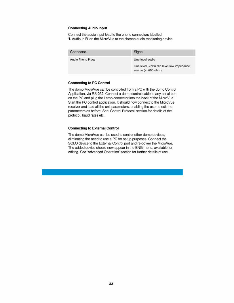
Connecting Audio Input
Connect the audio input lead to the phono connectors labelled
‘L Audio In R’ on the MicroVue to the chosen audio monitoring device.
Connector Signal
Audio Phono Plugs Line level audio
Line level -2dBu clip level low impedance
source (< 600 ohm)
Connecting to PC Control
The domo MicroVue can be controlled from a PC with the domo Control
Application, via RS-232. Connect a domo control cable to any serial port
on the PC and plug the Lemo connector into the back of the MicroVue.
Start the PC control application. It should now connect to the MicroVue
receiver and load all the unit parameters, enabling the user to edit the
parameters as before. See ‘Control Protocol’ section for details of the
protocol, baud rates etc.
Connecting to External Control
The domo MicroVue can be used to control other domo devices,
eliminating the need to use a PC for setup purposes. Connect the
SOLO device to the External Control port and re-power the MicroVue.
The added device should now appear in the ENG menu, available for
editing. See ‘Advanced Operation’ section for further details of use.
24
10 Advanced Operation
The following section should be read by users concerned with the more
advanced operation of the domo MicroVue. Topics covered include:
• Advanced Functions of the Touch Screen Controller.
• Advanced features of the ClearCam control page.
• Using the External Antenna Function.
• Using the Monitor Input Function.
• Controlling other domo devices from the MicroVue.
• Using the optional NDT Recorder.
• Using the optional micro-video discrete viewer.
• Connecting the PC Controller.
• Upgrading the MicroVue receiver software.

25
10.1 Advanced Functions of the Touch Screen Controller
Touch Screen Controller Menu Tree
The menu structure of the MicroVue touch screen controller is shown
below. Only the principle menu screens are shown.
Main Status Screen
Engineering Screen
System Setup Screen
Figure 9 The MicroVue principle screens
MicroVue Receiver menu
26
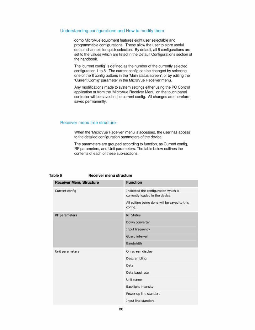
Understanding configurations and How to modify them
domo MicroVue equipment features eight user selectable and
programmable configurations. These allow the user to store useful
default channels for quick selection. By default, all 8 configurations are
set to the values which are listed in the Default Configurations section of
the handbook.
The ‘current config’ is defined as the number of the currently selected
configuration 1 to 8. The current config can be changed by selecting
one of the 8 config buttons in the ‘Main status screen’, or by editing the
‘Current Config’ parameter in the MicroVue Receiver menu.
Any modifications made to system settings either using the PC Control
application or from the ‘MicroVue Receiver Menu’ on the touch panel
controller will be saved in the current config. All changes are therefore
saved permanently.
Receiver menu tree structure
When the ‘MicroVue Receiver’ menu is accessed, the user has access
to the detailed configuration parameters of the device.
The parameters are grouped according to function, as Current config,
RF parameters, and Unit parameters. The table below outlines the
contents of each of these sub-sections.
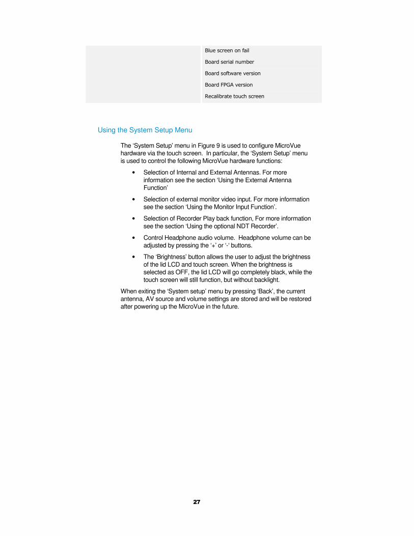
Table 6 Receiver menu structure
Receiver Menu Structure Function
Current config Indicated the configuration which is
currently loaded in the device.
All editing being done will be saved to this
config.
RF parameters RF Status
Down converter
Input frequency
Guard interval
Bandwidth
Unit parameters On screen display
Descrambling
Data
Data baud rate
Unit name
Backlight intensity
Power up line standard
Input line standard
27
Blue screen on fail
Board serial number
Board software version
Board FPGA version
Recalibrate touch screen
Using the System Setup Menu
The ‘System Setup’ menu in Figure 9 is used to configure MicroVue
hardware via the touch screen. In particular, the ‘System Setup’ menu
is used to control the following MicroVue hardware functions:
• Selection of Internal and External Antennas. For more
information see the section ‘Using the External Antenna
Function’
• Selection of external monitor video input. For more information
see the section ‘Using the Monitor Input Function’.
• Selection of Recorder Play back function, For more information
see the section ‘Using the optional NDT Recorder’.
• Control Headphone audio volume. Headphone volume can be
adjusted by pressing the ‘+’ or ‘-‘ buttons.
• The ‘Brightness’ button allows the user to adjust the brightness
of the lid LCD and touch screen. When the brightness is
selected as OFF, the lid LCD will go completely black, while the
touch screen will still function, but without backlight.
When exiting the ‘System setup’ menu by pressing ‘Back’, the current
antenna, AV source and volume settings are stored and will be restored
after powering up the MicroVue in the future.
28
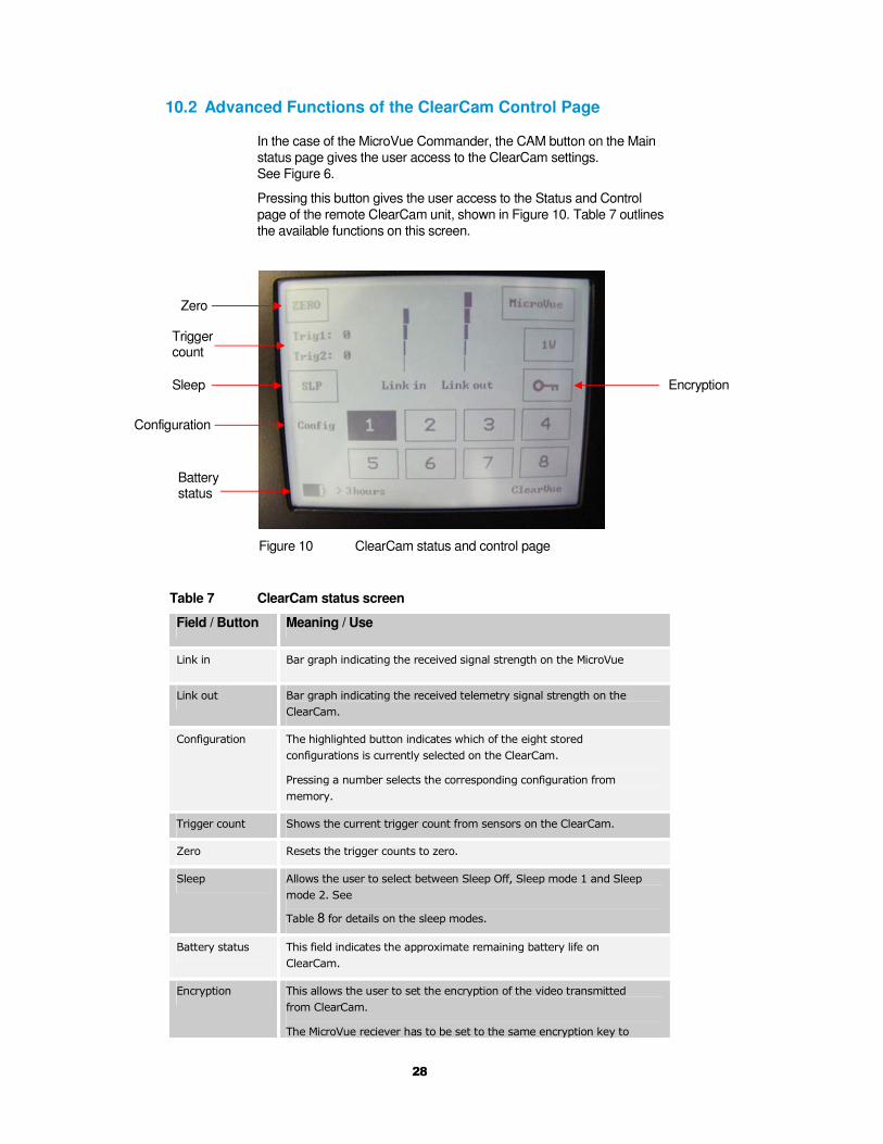
10.2 Advanced Functions of the ClearCam Control Page
In the case of the MicroVue Commander, the CAM button on the Main
status page gives the user access to the ClearCam settings.
See Figure 6.
Pressing this button gives the user access to the Status and Control
page of the remote ClearCam unit, shown in Figure 10. Table 7 outlines
the available functions on this screen.
Figure 10 ClearCam status and control page
Table 7 ClearCam status screen
Field / Button Meaning / Use
Link in Bar graph indicating the received signal strength on the MicroVue
Link out Bar graph indicating the received telemetry signal strength on the
ClearCam.
Configuration The highlighted button indicates which of the eight stored
configurations is currently selected on the ClearCam.
Pressing a number selects the corresponding configuration from
memory.
Trigger count Shows the current trigger count from sensors on the ClearCam.
Zero Resets the trigger counts to zero.
Sleep Allows the user to select between Sleep Off, Sleep mode 1 and Sleep
mode 2. See
Table 8 for details on the sleep modes.
Battery status This field indicates the approximate remaining battery life on
ClearCam.
Encryption This allows the user to set the encryption of the video transmitted
from ClearCam.
The MicroVue reciever has to be set to the same encryption key to
Configuration
Trigger count
Sleep
Zero
Battery status
Encryption
29
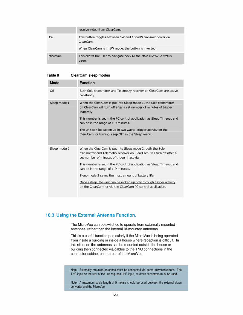
receive video from ClearCam.
1W This button toggles between 1W and 100mW transmit power on
ClearCam.
When ClearCam is in 1W mode, the button is inverted.
MicroVue This allows the user to navigate back to the Main MicroVue status
page.
Table 8 ClearCam sleep modes
Mode Function
Off Both Solo transmitter and Telemetry receiver on ClearCam are active
constantly.
Sleep mode 1 When the ClearCam is put into Sleep mode 1, the Solo transmitter
on ClearCam will turn off after a set number of minutes of trigger
inactivity.
This number is set in the PC control application as Sleep Timeout and
can be in the range of 1-9 minutes.
The unit can be woken up in two ways: Trigger activity on the
ClearCam, or turning sleep OFF in the Sleep menu.
Sleep mode 2 When the ClearCam is put into Sleep mode 2, both the Solo
transmitter and Telemetry receiver on ClearCam will turn off after a
set number of minutes of trigger inactivity.
This number is set in the PC control application as Sleep Timeout and
can be in the range of 1-9 minutes.
Sleep mode 2 saves the most amount of battery life.
Once asleep, the unit can be woken up only through trigger activity
on the ClearCam, or via the ClearCam PC control application.
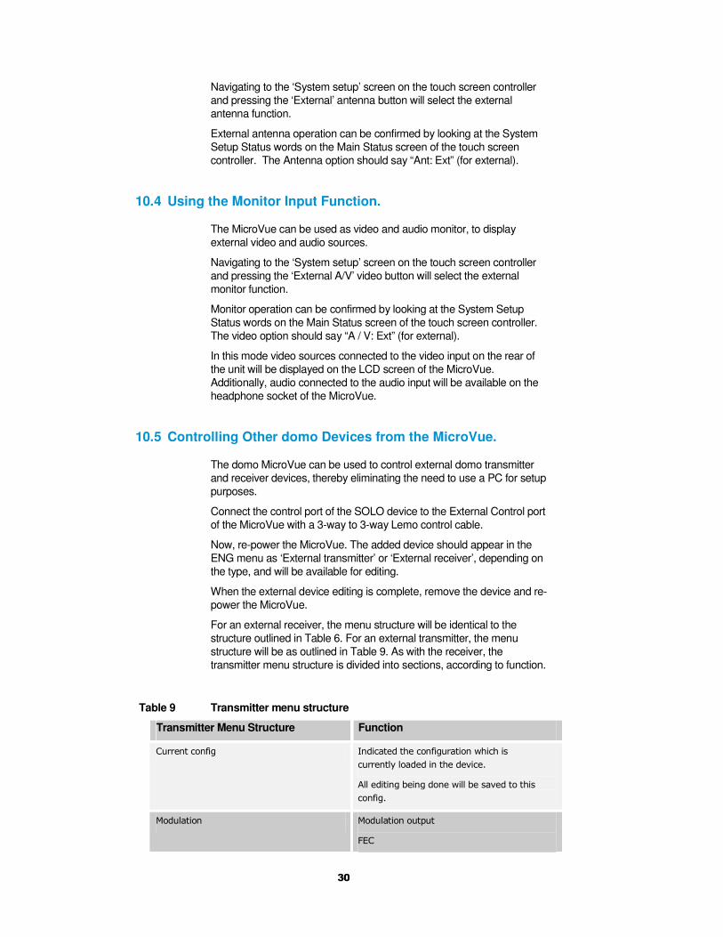
10.3 Using the External Antenna Function.
The MicroVue can be switched to operate from externally mounted
antennas, rather than the internal lid-mounted antennas.
This is a useful function particularly if the MicroVue is being operated
from inside a building or inside a house where reception is difficult. In
this situation the antennas can be mounted outside the house or
building then connected via cables to the TNC connections in the
connector cabinet on the rear of the MicroVue.
Note: Externally mounted antennas must be connected via domo downconverters. The
TNC input on the rear of the unit requires UHF input, so down converters must be used.
Note: A maximum cable length of 5 meters should be used between the external down
converter and the MicroVue.
30
Navigating to the ‘System setup’ screen on the touch screen controller
and pressing the ‘External’ antenna button will select the external
antenna function.
External antenna operation can be confirmed by looking at the System
Setup Status words on the Main Status screen of the touch screen
controller. The Antenna option should say “Ant: Ext” (for external).
10.4 Using the Monitor Input Function.
The MicroVue can be used as video and audio monitor, to display
external video and audio sources.
Navigating to the ‘System setup’ screen on the touch screen controller
and pressing the ‘External A/V’ video button will select the external
monitor function.
Monitor operation can be confirmed by looking at the System Setup
Status words on the Main Status screen of the touch screen controller.
The video option should say “A / V: Ext” (for external).
In this mode video sources connected to the video input on the rear of
the unit will be displayed on the LCD screen of the MicroVue.
Additionally, audio connected to the audio input will be available on the
headphone socket of the MicroVue.
10.5 Controlling Other domo Devices from the MicroVue.
The domo MicroVue can be used to control external domo transmitter
and receiver devices, thereby eliminating the need to use a PC for setup
purposes.
Connect the control port of the SOLO device to the External Control port
of the MicroVue with a 3-way to 3-way Lemo control cable.
Now, re-power the MicroVue. The added device should appear in the
ENG menu as ‘External transmitter’ or ‘External receiver’, depending on
the type, and will be available for editing.
When the external device editing is complete, remove the device and re-
power the MicroVue.
For an external receiver, the menu structure will be identical to the
structure outlined in Table 6. For an external transmitter, the menu
structure will be as outlined in Table 9. As with the receiver, the
transmitter menu structure is divided into sections, according to function.
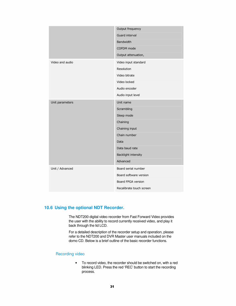
Table 9 Transmitter menu structure
Transmitter Menu Structure Function
Current config Indicated the configuration which is
currently loaded in the device.
All editing being done will be saved to this
config.
Modulation Modulation output
FEC
31
Output frequency
Guard interval
Bandwidth
COFDM mode
Output attenuation,
Video and audio Video input standard
Resolution
Video bitrate
Video locked
Audio encoder
Audio input level
Unit parameters Unit name
Scrambling
Sleep mode
Chaining
Chaining input
Chain number
Data
Data baud rate
Backlight intensity
Advanced
Unit / Advanced Board serial number
Board software version
Board FPGA version
Recalibrate touch screen
10.6 Using the optional NDT Recorder.
The NDT200 digital video recorder from Fast Forward Video provides
the user with the ability to record currently received video, and play it
back through the lid LCD.
For a detailed description of the recorder setup and operation, please
refer to the NDT200 and DVR Master user manuals included on the
domo CD. Below is a brief outline of the basic recorder functions.
Recording video
• To record video, the recorder should be switched on, with a red
blinking LED. Press the red ‘REC’ button to start the recording
process.
32
Playing back video
• Press the LIST soft button to list all the recorded clips currently
on the hard drive.
• Either LOAD ALL CLIPS, or scroll down with the circular “iPod
style” button to the desired clip and press LOAD.
• Press EXIT to go to the main display screen.
• Now press Play to start playback.
• The DVR will stop playing at the end of the loaded clip(s) if
Loop Playback is off, or continue from the first frame if Loop
Playback is on.
Offloading and Deleting video
• The NDT200 comes with application software called the DVR
Master. This allows the user to set up the device, and also to
access the DVR hard drive.
• Begin by following the installation instructions in the NDT200
DVR Master User’s Manual. (This step is omitted
subsequently).
• Connect the DVR to the PC with the supplied USB cable, and
switch on the DVR. Open the DVR Master application.
• Switch to the DISK tab. Click the ‘Access hard drive using USB’
box to connect the PC to the DVR via USB.
• Now files can be downloaded to the PC using Windows
Explorer.
• When the download is complete, untick the ‘Access hard drive
using USB’ box. Video can now be deleted with the ‘Delete All
Video (Format)’ button. Always use the DVR Master software to
delete unwanted video.
10.7 Using the optional micro-video discrete viewer.
Plug the micro-video discrete viewer into its back panel connector and
flick the power switch on the micro viewer to On.
Video will be displayed on the screen. The brightness can be adjusted
with the wheel at the side of the unit.
After a certain period of inactivity, the micro viewer will go to sleep. Bring
the unit out of sleep by touching the PTZ joystick.
Currently, the PTZ option is not yet supported.
10.8 Connecting the PC Controller
Advanced control of the MicroVue system is available by using the PC
control applications. This can be achieved by connecting a PC RS-232
port to the 3 pin Lemo control port

33
Selection of device to control
The MicroVue receiver is controlled by the solo_rx_ctrl.exe application
available on the CD delivered with the product. Should the user want to
control the MicroVue receiver with the PC, simply connect the PC to the
PC Control input of the MicroVue and open the Control Application.
Should an external transmitter or receiver be currently plugged into the
External Control port of the MicroVue, and the user has navigated into
the ‘External Receiver’ or ‘External Transmitter’ menu structure on the
touch screen, connecting the PC Control Application at this stage will
cause this current device to be edited by the PC application.
Note that exact file names may change as software version information is a part of domo
file names.
Connecting to the PC
Installation of the control program is as simple as copying it from the CD
to a suitable location on the PC. No install shield routine is launched.
Note that the controllers generate their own log and initialisation files, so
it is best to create a dedicated directory for these applications, perhaps
with links to the applications from the desktop of the PC.
Use the supplied cables to connect the chosen COM port(s) of the PC
to unit(s) to be configured.
Launch each application in turn by double clicking or using the run
command.
Connection with a SOLO product should be automatic, but the user can
force selection of the correct COM port using the drop down, followed by
the “Connect” button.
Errors such as the following may appear during the connection process
if the PC is unable to automatically ascertain which unit is connected to
which COM port.
• Error attempting to read invalid address
• Error has occurred during polling, polling has been disabled
For both controllers, changes can be made to the unit configuration
using the drop down and data entry fields.
Changes are only applied to the unit when the “Apply” button is clicked.
Current values, as running in the unit, can be read using the “Refresh”
button.
Parameters that are status information only appear in greyed in the
application.
Further engineering and configuration controls can be found within the
“Options” and “File” drop down menus in the application title bars.

34
Figure 11 Receiver PC control application
Note: The terminology DVB-T refers to the 8,7,6MHz wide bandwidth modulation
employed in the SOLO2 products. The SOLO4 product is also capable of DVB-T, but this
mode is not recommended for normal operation
Narrowband / DVB-T
The MicroVue is capable of receiving transmission in 6/7/8MHz wide
DVB-T OFDM only. The SOLO4 receiver is capable of receiving
transmissions in Narrowband and DVB-T. For receiving the
transmissions from a SOLO2 transmitter the ‘DVB-T’ radio button
should be selected. For receiving the transmissions from a SOLO4
transmitter the ‘Narrowband’ radio button should be selected.
When the ‘Narrowband’ radio button is selected, then the ‘Narrowband’
column of parameters will become highlighted, and can be set.
If the ‘DVB-T’ radio button is selected, then the ‘DVB-T’ column of
parameters will become highlighted, and can be set.
Input Frequency
The receive frequency can be changed by entering the new desired
frequency in this field.
35
Down converter LO
This field allows definition of the local oscillator frequency in the
connected downconverters.
For domo supplied downconverters, this should be set as follows:
• 1880MHz for S band transmissions (2.28 to 2.55GHz)
• 1700MHz for L band transmissions (1.15 to 1.4GHz).
Down converter LO side
This field allows definition of the local oscillator side.
For domo supplied downconverters, this should be set as follows:
• LOW for S band transmissions (2.28 to 2.55GHz)
• HIGH for L band transmissions (2.28 to 2.55GHz)
OFDM Bandwidth
This field displays the width of the received OFDM signal and should be
set to 2.5MHz for normal SOLO4 system operation, and should be set
to 8MHz for normal SOLO2 system operation.
OFDM Guard Interval
In this field the user selects the guard interval which matches the
transmitter. For SOLO4 systems typically a guard interval of 1/16 is
used, however on very long range transmissions a guard interval of 1/8
may be employed. For SOLO4 systems typically a guard interval of
1/32 is used, however on very long range transmissions a guard interval
of 1/8 may be employed.
OFDM Mode (Status Only)
This field displays the COFDM constellation that is being demodulated
at the receiver. In normal operation this will match that selected at the
transmitter.
OFDM FEC (Status Only)
This field displays the COFDM FEC (Forward Error Correction) that is
being demodulated at the receiver. In normal operation this will match
that selected at the transmitter.
Input SNR (Status Only)
For each IF input, the SNR (Signal to Noise Ratio) is reported. Values in
the order of 18dB to 22dB represent strong received signals, whilst
values in the order of 5dB represent poor received signals which will
likely give rise to decoding errors.
36
BER Pre Viterbi (Status Only)
This figure is for engineering use and gives a representation of the error
rate prior to the error correction techniques having been applied in the
receiver.
BER Post Viterbi (Status Only)
This figure gives a measure of the bit error rate after error correction
techniques have been applied in the receiver. Any numbers greater than
0 in this field indicate the presence of un-correctable errors in the
received stream, and thus picture glitching and audio artefacts will
occur.
Input Level (Status Only)
This figure indicates the received signal level at the two receiver inputs.
Normal Operation will occur when the input level is between –15 and –
90 dBm. Signals greater than –15 may be too powerful and cause
damage. Signal less than –90dBm may be too weak and cause picture
loss (typical link failure will occur between –95 and –99dBm).
Demod Lock Status (Status Only)
This indicates whether the demodulators are successfully locked to the
RF signal.
Data
With this ON / OFF control the user can select whether the receiver
extracts any data component that may be in the transmitted stream.
Such data components are presented at the receiver DATA output port.
Note that current SOLO transmitter products do not physically feature a reciprocal RS232
level DATA input
Data Baud Rate (Status Only)
This field reports the baud rate of any RS232 serial data component that
is present and selected in the stream.
Input Line Standard (Status Only)
This field reports the line standard that is currently being, or last was,
decoded.
37
Power Up Line Standard
Using this field the user can select what line standard of video the
receiver will output (PAL / NTSC) when the receiver is first powered on
and before it has locked to an incoming RF signal.
NTSC Mode
With this control, when running in 525 line mode, the user can select
whether the NTSC composite output video has a 7.5 IRE pedestal
applied.
Blue Screen on Fail
When the link fails, the user can select between a blue field video output
(YES), and a freeze frame (NO) with this option.
Unit Name
This field allows the user to enter an identifier for the service that they
wish to receive. This must match that selected at the transmitter for the
service to be decoded. The unit name can be constructed of any eight
ASCII characters.
Descrambling
If the AES scrambling option has been purchased for the SOLO system
in use, then it is possible to encrypt the link. Descrambling must also be
enabled at the receiver by selecting AES128 or AES256 in the
descrambling field. At this point the user will need to ensure that the
correct key is in use at the receiver and this is done by selecting
Options / Write AES Key in the receiver controller.
The key is a 128bit value for AES128 and a 256bit value for AES256,
and is entered as 32 or 64 ASCII hexadecimal characters (0...F).
Decoder Lock Status (Status Only)
This field reports whether the video decoder is successfully locked to the
incoming digital bit stream.
Current Config
This field allows the user to select which of the 8 memory configs the
receiver is operating in. The receiver has 8 stored configurations and
the user can move between them by setting the appropriate number in
this field. Changes made to other settings by the user will automatically
be stored in the configuration number indicated by this field.
38
Serial Number (Status Only)
This status information is the electronic serial number of the transmitter
PCB. This number can be exchanged with domo to purchase extra
licensable features, such as upgrades to support AES decryption.
Software Version (Status Only)
This status information describes the version of the software running in
the SOLO transmitter product.
FPGA Version (Status Only)
This information is for domo engineering use only.
Chaining
Chaining allows multiple services to be sent via one RF link. A receiver
may be connected to a transmitter to form a chaining or relay link. To
allow this, the chaining interfaces provided on the first receiver must be
connected to the second transmitter. Three modes of operation are
supported - no chaining (default), chaining mode, and relay mode. The
chaining mode allows two services (remote and local) to be combined.
The relay mode allows just the remote service to be transmitted turning
off the local service.
For chaining mode to operate correctly, the second unit in the chain
must operate at twice the transmit data rate from the first. If the first unit
is operating in QPSK rate 2/3 the second unit must operate in 16QAM
rate 2/3. If the first unit is operating in QPSK rate 1/3 the second unit
must operate in QPSK rate 2/3. The units must have different chaining
numbers selected, and the different unit names. For the relay mode to
operate correctly the second unit must have the transmit rate greater or
equal to the first unit.
Chaining is a licensable feature.
Options
Write License Code – open a further password protected box for
entering license codes for the activation of licensable features (e.g. AES
descrambling) in the receiver. Contact domo for support in applying
new licenses as required.
Write AES Key – opens a dialogue box for entering a 128bit AES
descrambling key, as 32 ASCII hexadecimal characters (0…F), or a
256bit AES descrambling key, as two 32 ASCII hexadecimal character
fields.
Change RS232 address – prompts the user to change the units RS232
address, which can be useful when connecting multiple units together
via a multi drop RS485 bus for control purposes.
Engineering – password protected access to further diagnostic tools.
Timeouts – password protected access to change timeouts used during
the serial communications between the unit and the controller.
39
Polling Enabled – selecting this option makes the control application
automatically refresh the data presented to the user every few seconds.
This can be useful when performing experiments to check transmission
performance, but can be disruptive when making configuration changes
if “All parameters” is selected from the Polling Options (see below)
Polling Options – presents the user with a choice of receiver
parameters to poll, and a frequency at which to do so. Further, selecting
a check box allows the polled parameters to be written to file.
Copy Config – allows the user to copy a stored configuration into
another selected configuration.
Restore Defaults – restores factory default settings in the receiver.
File
Change Logfile – opens a standard Windows file save dialogue box
which allows the user to change the path and name of the log file
generated by the application.
Exit – exits the SOLO receiver control application
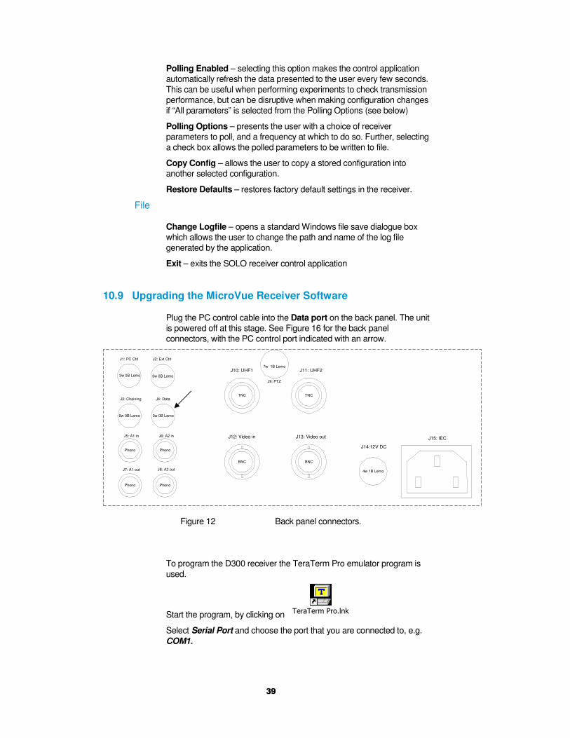
10.9 Upgrading the MicroVue Receiver Software
Plug the PC control cable into the Data port on the back panel. The unit
is powered off at this stage. See Figure 16 for the back panel
connectors, with the PC control port indicated with an arrow.
J14:12V DC
4w 1B Lemo
J12: Video in
BNC
J13: Video out
BNC
J10: UHF1
TNC
J11: UHF2
TNC
J1: PC Ctrl
3w 0B Lemo
J2: Ext Ctrl
3w 0B Lemo
J3: Chaining
6w 0B Lemo
J4: Data
3w 0B Lemo
Phono
J5: A1 in
Phono
J6: A2 in
Phono
J8: A2 out
Phono
J7: A1 out
J9: PTZ
7w 1B Lemo
J15: IEC
Figure 12 Back panel connectors.
To program the D300 receiver the TeraTerm Pro emulator program is
used.
Start the program, by clicking on TeraTerm Pro.lnk
Select Serial Port and choose the port that you are connected to, e.g.
COM1.
40
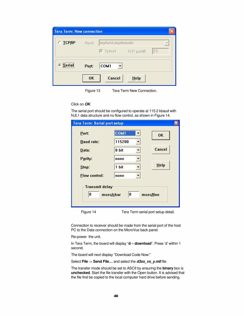
Figure 13 Tera Term New Connection.
Click on OK.
The serial port should be configured to operate at 115.2 kbaud with
N,8,1 data structure and no flow control, as shown in Figure 14.
Figure 14 Tera Term serial port setup detail.
Connection to receiver should be made from the serial port of the host
PC to the Data connection on the MicroVue back panel.
Re-power the unit.
In Tera Term, the board will display “d – download”. Press ‘d’ within 1
second.
The board will next display “Download Code Now:”
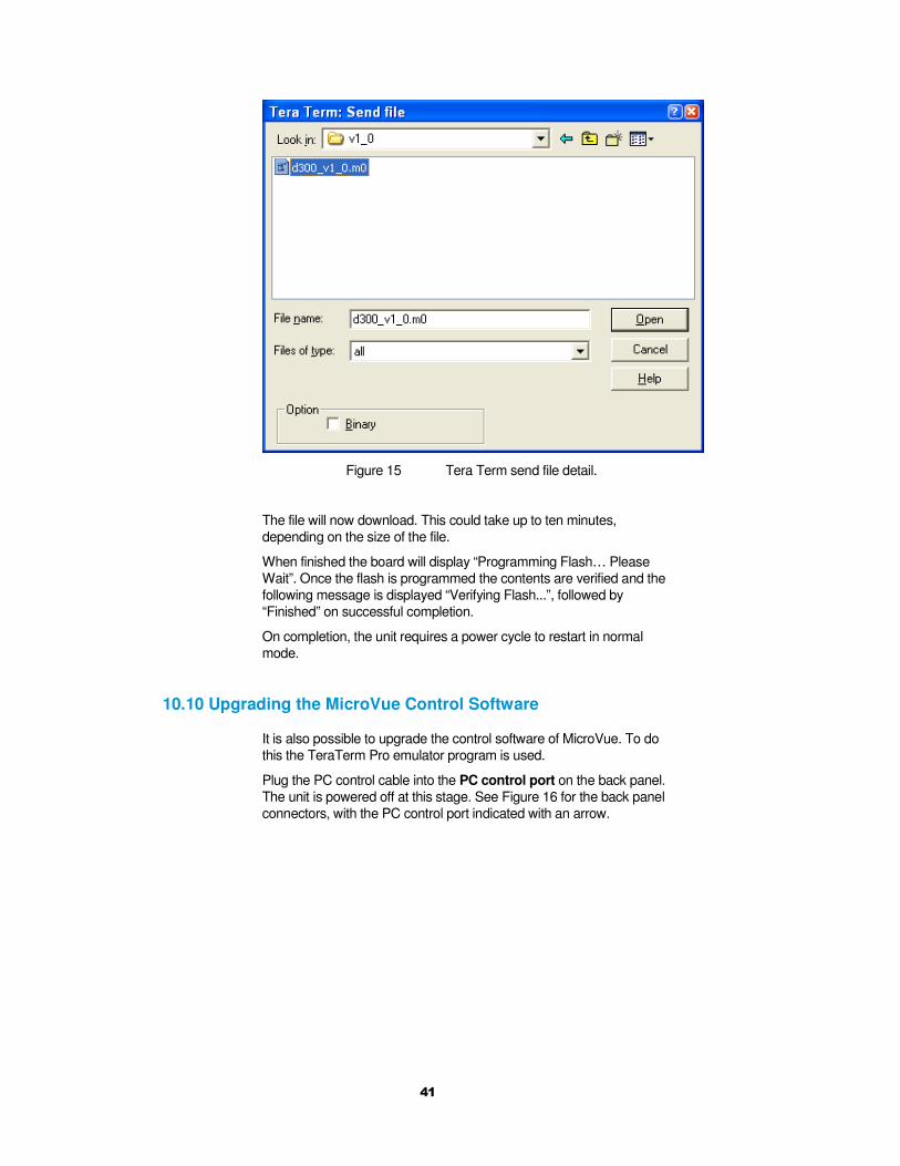
Select File -> Send File… and select the d3xx_vx_y.m0 file
The transfer mode should be set to ASCII by ensuring the binary box is
unchecked. Start the file transfer with the Open button. It is advised that
the file first be copied to the local computer hard drive before sending.
41
Figure 15 Tera Term send file detail.
The file will now download. This could take up to ten minutes,
depending on the size of the file.
When finished the board will display “Programming Flash… Please
Wait”. Once the flash is programmed the contents are verified and the
following message is displayed “Verifying Flash...”, followed by
“Finished” on successful completion.
On completion, the unit requires a power cycle to restart in normal
mode.
10.10 Upgrading the MicroVue Control Software
It is also possible to upgrade the control software of MicroVue. To do
this the TeraTerm Pro emulator program is used.
Plug the PC control cable into the PC control port on the back panel.
The unit is powered off at this stage. See Figure 16 for the back panel
connectors, with the PC control port indicated with an arrow.

42
J14:12V DC
4w 1B Lemo
J12: Video in
BNC
J13: Video out
BNC
J10: UHF1
TNC
J11: UHF2
TNC
J1: PC Ctrl
3w 0B Lemo
J2: Ext Ctrl
3w 0B Lemo
J3: Chaining
6w 0B Lemo
J4: Data
3w 0B Lemo
Phono
J5: A1 in
Phono
J6: A2 in
Phono
J8: A2 out
Phono
J7: A1 out
J9: PTZ
7w 1B Lemo
J15: IEC
Figure 16 Back panel connectors.
Start the program, by clicking on TeraTerm Pro.lnk
Select Serial Port and choose the port that you are connected to, e.g.
COM1
Figure 17 Tera Term New Connection.
Click on OK.
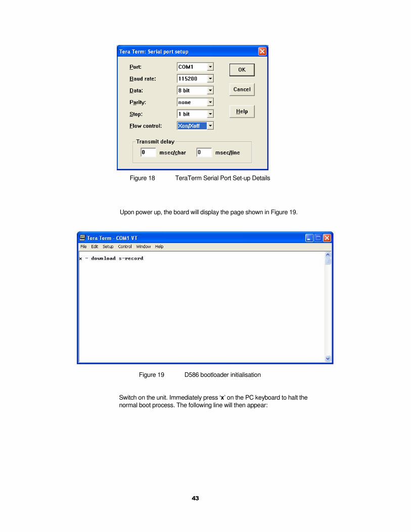
The serial port should be configured to operate at 115.2 kbaud with
N,8,1 as data structure and Xon / Xoff flow control. See Figure 18 for the
TeraTerm setup.
43
Figure 18 TeraTerm Serial Port Set-up Details
Upon power up, the board will display the page shown in Figure 19.
Figure 19 D586 bootloader initialisation
Switch on the unit. Immediately press ‘x’ on the PC keyboard to halt the
normal boot process. The following line will then appear:
44
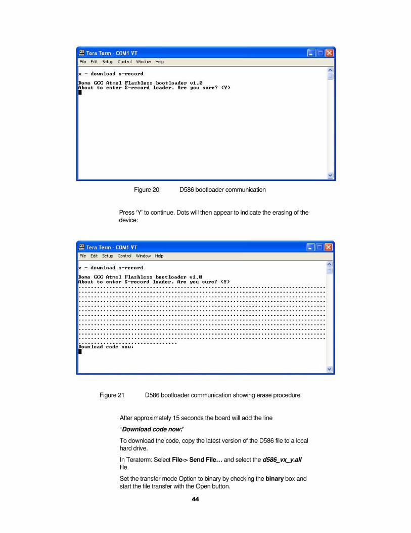
Figure 20 D586 bootloader communication
Press ‘Y’ to continue. Dots will then appear to indicate the erasing of the
device:
Figure 21 D586 bootloader communication showing erase procedure
After approximately 15 seconds the board will add the line
“Download code now:”
To download the code, copy the latest version of the D586 file to a local
hard drive.
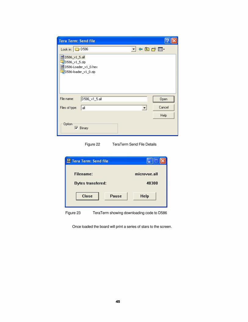
In Teraterm: Select File-> Send File… and select the d586_vx_y.all
file.
Set the transfer mode Option to binary by checking the binary box and
start the file transfer with the Open button.
45
Figure 22 TeraTerm Send File Details
Figure 23 TeraTerm showing downloading code to D586
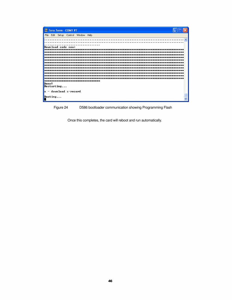
Once loaded the board will print a series of stars to the screen.
46
Figure 24 D586 bootloader communication showing Programming Flash
Once this completes, the card will reboot and run automatically.
47
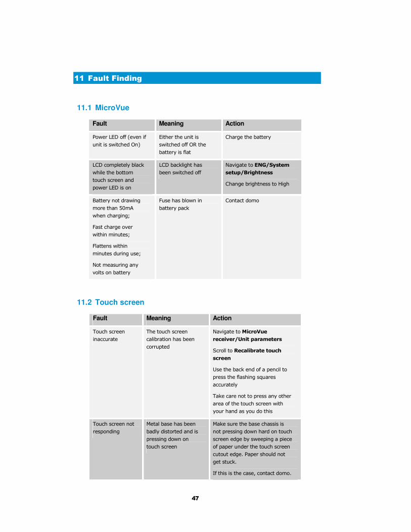
11 Fault Finding
11.1 MicroVue
Fault Meaning Action
Power LED off (even if
unit is switched On)
Either the unit is
switched off OR the
battery is flat
Charge the battery
LCD completely black
while the bottom
touch screen and
power LED is on
LCD backlight has
been switched off
Navigate to ENG/System
setup/Brightness
Change brightness to High
Battery not drawing
more than 50mA
when charging;
Fast charge over
within minutes;
Flattens within
minutes during use;
Not measuring any
volts on battery
Fuse has blown in
battery pack
Contact domo
11.2 Touch screen
Fault Meaning Action
Touch screen
inaccurate
The touch screen
calibration has been
corrupted
Navigate to MicroVue
receiver/Unit parameters
Scroll to Recalibrate touch
screen
Use the back end of a pencil to
press the flashing squares
accurately
Take care not to press any other
area of the touch screen with
your hand as you do this
Touch screen not
responding
Metal base has been
badly distorted and is
pressing down on
touch screen
Make sure the base chassis is
not pressing down hard on touch
screen edge by sweeping a piece
of paper under the touch screen
cutout edge. Paper should not
get stuck.
If this is the case, contact domo.
48
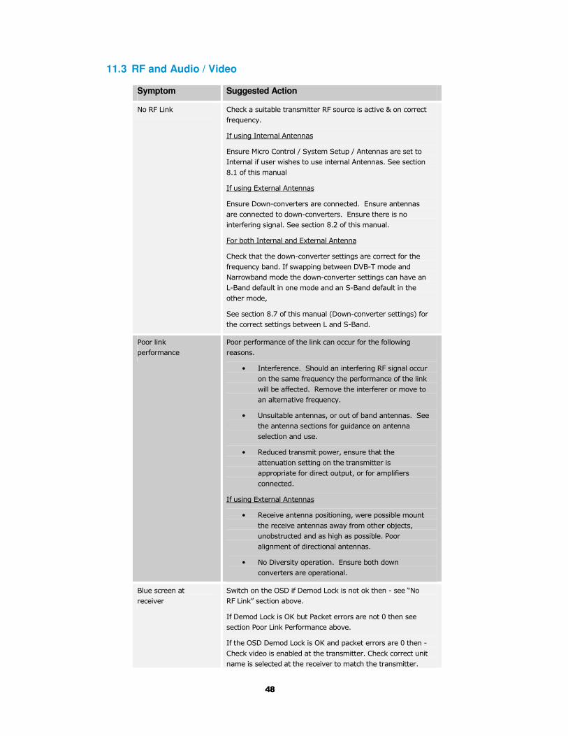
11.3 RF and Audio / Video
Symptom Suggested Action
No RF Link Check a suitable transmitter RF source is active & on correct
frequency.
If using Internal Antennas
Ensure Micro Control / System Setup / Antennas are set to
Internal if user wishes to use internal Antennas. See section
8.1 of this manual
If using External Antennas
Ensure Down-converters are connected. Ensure antennas
are connected to down-converters. Ensure there is no
interfering signal. See section 8.2 of this manual.
For both Internal and External Antenna
Check that the down-converter settings are correct for the
frequency band. If swapping between DVB-T mode and
Narrowband mode the down-converter settings can have an
L-Band default in one mode and an S-Band default in the
other mode,
See section 8.7 of this manual (Down-converter settings) for
the correct settings between L and S-Band.
Poor link
performance
Poor performance of the link can occur for the following
reasons.
• Interference. Should an interfering RF signal occur
on the same frequency the performance of the link
will be affected. Remove the interferer or move to
an alternative frequency.
• Unsuitable antennas, or out of band antennas. See
the antenna sections for guidance on antenna
selection and use.
• Reduced transmit power, ensure that the
attenuation setting on the transmitter is
appropriate for direct output, or for amplifiers
connected.
If using External Antennas
• Receive antenna positioning, were possible mount
the receive antennas away from other objects,
unobstructed and as high as possible. Poor
alignment of directional antennas.
• No Diversity operation. Ensure both down
converters are operational.
Blue screen at
receiver
Switch on the OSD if Demod Lock is not ok then - see “No
RF Link” section above.
If Demod Lock is OK but Packet errors are not 0 then see
section Poor Link Performance above.
If the OSD Demod Lock is OK and packet errors are 0 then -
Check video is enabled at the transmitter. Check correct unit
name is selected at the receiver to match the transmitter.
49
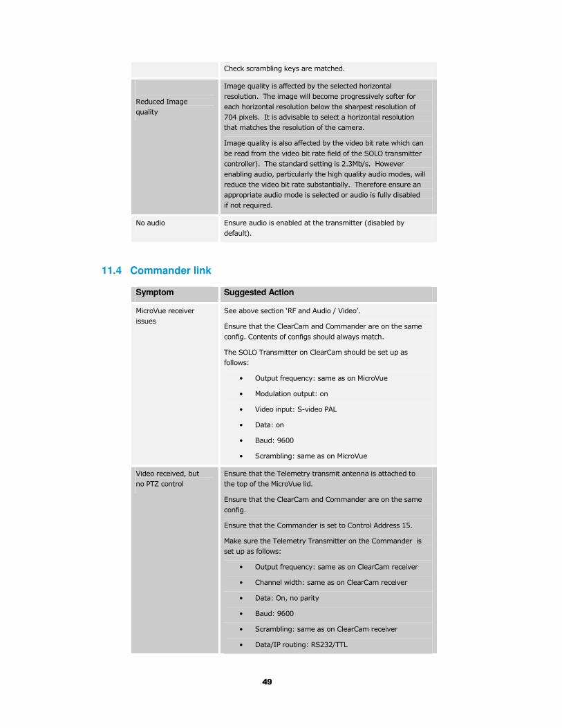
Check scrambling keys are matched.
Reduced Image
quality
Image quality is affected by the selected horizontal
resolution. The image will become progressively softer for
each horizontal resolution below the sharpest resolution of
704 pixels. It is advisable to select a horizontal resolution
that matches the resolution of the camera.
Image quality is also affected by the video bit rate which can
be read from the video bit rate field of the SOLO transmitter
controller). The standard setting is 2.3Mb/s. However
enabling audio, particularly the high quality audio modes, will
reduce the video bit rate substantially. Therefore ensure an
appropriate audio mode is selected or audio is fully disabled
if not required.
No audio Ensure audio is enabled at the transmitter (disabled by
default).
11.4 Commander link
Symptom Suggested Action
MicroVue receiver
issues
See above section ‘RF and Audio / Video’.
Ensure that the ClearCam and Commander are on the same
config. Contents of configs should always match.
The SOLO Transmitter on ClearCam should be set up as
follows:
• Output frequency: same as on MicroVue
• Modulation output: on
• Video input: S-video PAL
• Data: on
• Baud: 9600
• Scrambling: same as on MicroVue
Video received, but
no PTZ control
Ensure that the Telemetry transmit antenna is attached to
the top of the MicroVue lid.
Ensure that the ClearCam and Commander are on the same
config.
Ensure that the Commander is set to Control Address 15.
Make sure the Telemetry Transmitter on the Commander is
set up as follows:
• Output frequency: same as on ClearCam receiver
• Channel width: same as on ClearCam receiver
• Data: On, no parity
• Baud: 9600
• Scrambling: same as on ClearCam receiver
• Data/IP routing: RS232/TTL
50
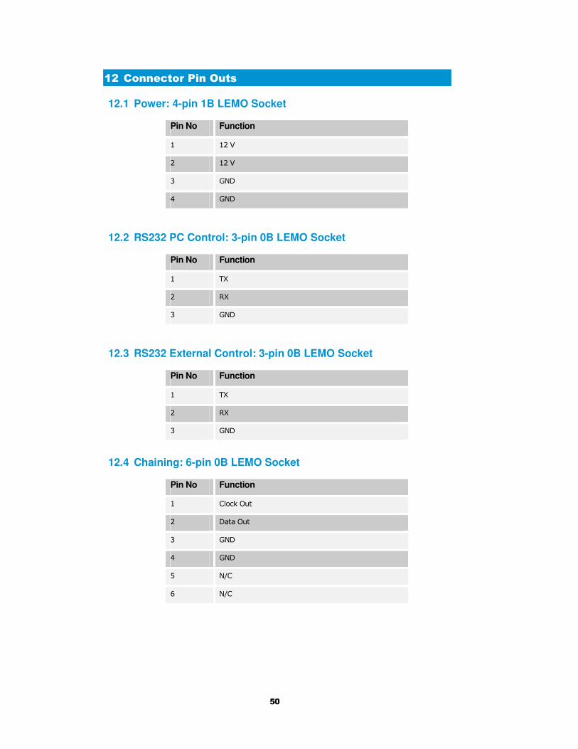
12 Connector Pin Outs
12.1 Power: 4-pin 1B LEMO Socket
Pin No Function
1 12 V
2 12 V
3 GND
4 GND
12.2 RS232 PC Control: 3-pin 0B LEMO Socket
Pin No Function
1 TX
2 RX
3 GND
12.3 RS232 External Control: 3-pin 0B LEMO Socket
Pin No Function
1 TX
2 RX
3 GND
12.4 Chaining: 6-pin 0B LEMO Socket
Pin No Function
1 Clock Out
2 Data Out
3 GND
4 GND
5 N/C
6 N/C
51
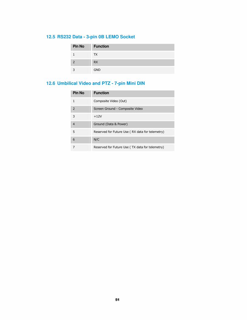
12.5 RS232 Data - 3-pin 0B LEMO Socket
Pin No Function
1 TX
2 RX
3 GND
12.6 Umbilical Video and PTZ - 7-pin Mini DIN
Pin No Function
1 Composite Video (Out)
2 Screen Ground - Composite Video
3 +12V
4 Ground (Data & Power)
5 Reserved for Future Use ( RX data for telemetry)
6 N/C
7 Reserved for Future Use ( TX data for telemetry)

52
13 Control Protocols
The following section describes the control protocol employed on the
RS232 link for controlling the SOLO transmitters and receiver
equipment.
Connection details are detailed in previous sections.
Note that only features that are licensed for use in the SOLO units can be controlled. The
protocols listed here cover all possible features. Attempting to activate an unlicensed
feature will simply result in the command being ignored by the SOLO unit.
13.1 RS232 Control – General Principles
The physical interface is RS232 but this can be converted to RS 485
with an external adapter where multiple units are controlled over one RS
485 bus.
Normal operation involves sending a packet from the control device
(normally a PC) to the device being controlled. If the packet satisfies an
address integrity check, then the controlled device will action the
command and send a reply.
For compatibility with modems an ASCII style protocol is used.
Ports are set for 8 bits, No parity, 1 stop
13.2 Packet Structure Sending (from PC)
ASCII Value
STX 02h Start byte
0-9 30h-39h 4 byte unit address. In range 0-9999
R 20h-7Eh 1 byte command type. r read, w write or m misc
I 20h-7E 1 byte indicator of internal data block
ABC 20h-7Eh Command –three byte mnemonic
; 3Bh Separator
PQR 20h-7Eh Data –Optional, variable length
; 3Bh Separator
X 20h-7Eh Sum Check
ETX 03h End byte
53
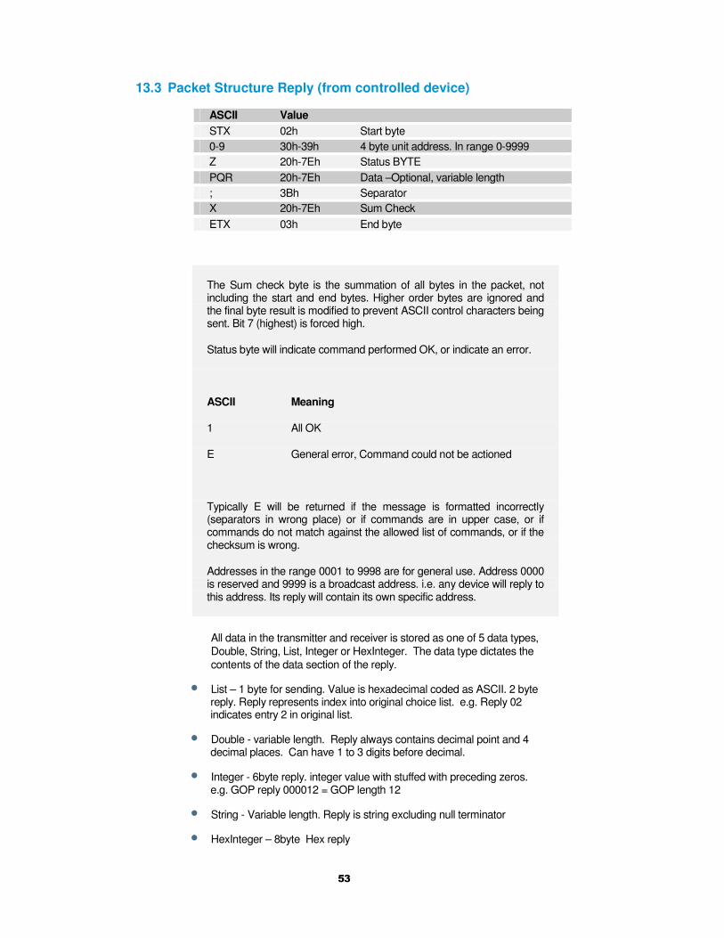
13.3 Packet Structure Reply (from controlled device)
ASCII Value
STX 02h Start byte
0-9 30h-39h 4 byte unit address. In range 0-9999
Z 20h-7Eh Status BYTE
PQR 20h-7Eh Data –Optional, variable length
; 3Bh Separator
X 20h-7Eh Sum Check
ETX 03h End byte
The Sum check byte is the summation of all bytes in the packet, not including the start and end bytes. Higher order bytes are ignored and the final byte result is modified to prevent ASCII control characters being sent. Bit 7 (highest) is forced high.
Status byte will indicate command performed OK, or indicate an error.
ASCII Meaning
1 All OK
E General error, Command could not be actioned
Typically E will be returned if the message is formatted incorrectly (separators in wrong place) or if commands are in upper case, or if commands do not match against the allowed list of commands, or if the checksum is wrong.
Addresses in the range 0001 to 9998 are for general use. Address 0000 is reserved and 9999 is a broadcast address. i.e. any device will reply to this address. Its reply will contain its own specific address.
All data in the transmitter and receiver is stored as one of 5 data types,
Double, String, List, Integer or HexInteger. The data type dictates the
contents of the data section of the reply.
• List – 1 byte for sending. Value is hexadecimal coded as ASCII. 2 byte reply. Reply represents index into original choice list. e.g. Reply 02 indicates entry 2 in original list.
• Double - variable length. Reply always contains decimal point and 4 decimal places. Can have 1 to 3 digits before decimal.
• Integer - 6byte reply. integer value with stuffed with preceding zeros. e.g. GOP reply 000012 = GOP length 12
• String - Variable length. Reply is string excluding null terminator
• HexInteger – 8byte Hex reply

54
13.4 Receiver Command List
Type ‘1’ messages for Tuner / Demod
Description Type Block Command Data Sent
Data Type
Input Frequency
r/w 1 ipf This is the frequency received by the antenna. Decimal point allowed.
Double
Down Converter LO
r/w 1 dco Decimal point allowed.
Double
Down Converter LO Side
r/w 1 los 0=low 1=high
List
OFDM Bandwidth
r/w 1 wid N.Band Mode 3 = 2.5MHz DVBT Mode 0 = 8MHz 1 = 7MHz 2 = 6MHz
List
OFDM Modulation Mode
r 1 mod N.Band Mode 0 = QPSK 1 = 16QAM DVBT Mode 0 = QPSK 1 = 16QAM 2 = 64QAM
List
OFDM FEC r 1 fec N.Band Mode 1 = 2/3 2 = 1/3 DVBT Mode 0 = 1/2 1 = 2/3 2 = 3/4 3 = 5/6 4 = 7/8
List
OFDM Guard
N.Band Mode r/w DVBT Mode r
1 gua N.Band Mode 1 = 1/16 2 = 1/8 DVBT Mode 0 = 1/32 1 = 1/16 2 = 1/8 3 = 1/4
List
OFDM Pol
r 1 pol 0 = Normal 1 = Inverted
List
Input SNR A r 1 snr Input SNR in dB Double
Input SNR B r 1 mer Input SNR in dB Double
Input SNR C r 1 cer Input SNR in dB Double
Input SNR D r 1 dnr Input SNR in dB Double
BER Pre Viterbi
r 1 pre Pre Viterbi x 10-6 Int
BER Post Viterbi
r 1 pos Post Viterbi x 10-6 Int
Packet errors r 1 pkt Int
Lock Status r 1 loc 0 = Not Locked 1 = Locked
List
Input Level A r 1 ina Input Level in dBm Double
Input Level B r 1 inb Input Level in dBm Double
Input Level C r 1 Inc Input Level in dBm Double
Input Level D r 1 ind Input Level in dBm Double

55
Type ‘g’ messages for Unit level commands
Description Type Block Command Data Sent
Data Type
Unit Mode r/w g udm 0 = Narrow Band 1 = DVBT
List
Input Mode r/w g mod 0 = RF Input 8 = Chaining Input
List
LNB Power r/w g lnb 0 = OFF 1 = ON
List
Unit RS232 Address
r/w g add Unit Address 0000 - 9999
Integer
Software Version r g sof Software Version Number
String
FPGA Version r g fpg FPGA Version Number
String
Serial Number r g ser Hex based Serial Number
String
License Code w g lco License number to enable certain features
List
On Screen Display
r/w g osd 0 = Off 1 = Channel A 2 = Channel B 3 = Channel C 4 = Channel D
List
Type ‘e’ messages for Decoder configuration commands
Description Type Block Command Data Sent
Data Type
Unit Number r/w e ser Index into List of programs
List
Preferred Unit Name
r/w e def Preferred Unit Name
String
525 Video Format r/w e 525 0 = YUV 1 = NTSC 2 = NTSC No Ped
List
625 Video Format r/w e 625 0=YUV 1 = PAL
List
Locked r e loc 0 = No 1 = Yes
List
Line Standard r e lin 0 = 625 1 = 525
Integer
Fail mode r/w e fai 0 = freeze 1 = blue
list
Power Up Line Standard
r/w e pwr 0 = 625 1 = 525
list
Service Scrambling Status
r e scr 0 = Clear 1 =Scrambled

56
Type ‘d’ messages for Memory configuration commands
Description Type Block Command Data Sent
Data Type
Store Current Configuration to Memory
r/w d sto Config Address (1 to 9)
Integer
Load Configuration from Memory into current
r/w d loa Config Address (1 to 9)
Integer
Restore Default Build
r/w d def 0 = No 1 = Yes
List
Read number of last config loaded
r d las Config Address
Integer
Type ‘z’ messages for Descrambling commands
Description Type Block Command Data Sent
Data Type
Descrambling r/w z des 0 = Off 1 = ABS 4 = AES128 5 = AES128+ 6 = AES256 7= AES256+
List
ABS Scrambling Key
w z ebs Alink basic scrambling key
8-digit hex string
AES Scrambling Key – lower 128 bits
w z aes Advanced Encryption Standard – lower 128 bits
32-digit hex string
AES Scrambling Key – upper 128 bits used in AES256 only
w z a25 Advanced Encryption Standard – upper 128 bits
32-digit hex string
Type ‘t’ messages for RS232 data pipe commands
Description Type Block Command Data Sent Data Type
Data On/Off r/w t dat 0 = Off 1 = On
List
Data Baudrate
r t bau 2 = 1200 baud 3 = 2400 baud 4 = 4800 baud 5 = 9600 baud 6 = 19200 baud 7 = 38400 baud
8 = 57600 baud 9 = 115200 baud
List
Data Parity r/w t par 0 = none 1 = even 2 = odd
List

57
14 Default Configurations
This section tabulates the default configuration settings for domo SOLO
products.
Item MicroVue
Config 1 to 4
MicroVue
Config 5 to 8
LNB Power ON ON
Frequency 2405MHz 1395MHZ
Down converter
LO
1880 1700
LO Side Low High
Unit Address 0001 0001
Default Service Solo-01 (SOLO4) Unit 1
(SOLO2)
Solo-01 (SOLO4) Unit 1
(SOLO2)
Video Fail Blue Field Blue Field
Data OFF OFF
De-Scrambling OFF OFF
AES Key None None

58
Cobham Surveillance
Domo Products 11 Manor Court, Barnes Wallis Road, Segensworth,
Hampshire, PO15 5TH, England
T: +44 (0)1489 566 750 F: +44 (0)1489 880 538