Embed Size (px)
Citation preview

8/3/2019 Microwave Engineering Microwave Networks What Are Microwaves 589
http://slidepdf.com/reader/full/microwave-engineering-microwave-networks-what-are-microwaves-589 1/26
Microwave Engineering
Microwave Networks
± What are Microwaves? ± S-parameters
± Power Dividers
± Couplers
± Filters
± Amplifiers

8/3/2019 Microwave Engineering Microwave Networks What Are Microwaves 589
http://slidepdf.com/reader/full/microwave-engineering-microwave-networks-what-are-microwaves-589 2/26
Microwave engineering: Engineering and design of
communication/navigation systems in the microwavefrequency range.
Microwave Engineering
Applications: Microwave oven, Radar, Satellite communi-
cation, direct broadcast satellite (DBS) television, personal
communication systems (PCSs) etc.

8/3/2019 Microwave Engineering Microwave Networks What Are Microwaves 589
http://slidepdf.com/reader/full/microwave-engineering-microwave-networks-what-are-microwaves-589 3/26
What are Microwaves? (Pozar Sec. 1.1)
P = 30 cm: f = 3 x 10⁸/ 30 x 10-2 = 1 GHz
P = 1 cm: f = 3 x 10⁸/ 1x 10-2 = 30 GHz
Microwaves: 30 cm ± 1 cm
Millimeter waves: 10 mm ± 1 mm
(centimeter waves)
P = 10 mm: f = 3 x 10⁸/ 10 x 10-3 = 30 GHz
P = 1 mm: f = 3 x 10⁸/ 1x 10-3 = 300 GHz
m
sm Hz
/103 wavelength
clightof velocityf frequency 8
PPv!!
Note: 1 Giga = 109

8/3/2019 Microwave Engineering Microwave Networks What Are Microwaves 589
http://slidepdf.com/reader/full/microwave-engineering-microwave-networks-what-are-microwaves-589 4/26
What are Microwaves?
1 cm
f =10 kHz, P = c/f = 3 x 10⁸/ 10 x 103 = 3000 m
Phase delay = (2T or 360r) x Physical length/Wavelength
f =10 GHz, P = 3 x 10⁸/ 10 x 109 = 3 cm
Electrical length =1 cm/3000 m = 3.3 x 10⁻⁶ P, Phase delay = 0.0012r
RF
Microwave
Electrical length = 0.33 P, Phase delay = 118.8r !!!
1P | 360 r
Electrically long - The phase of a voltage or current changes
significantly over the physical extent of the device
Electrical length = Physical length/Wavelength (expressed in P)
8/3/2019 Microwave Engineering Microwave Networks What Are Microwaves 589
http://slidepdf.com/reader/full/microwave-engineering-microwave-networks-what-are-microwaves-589 5/26
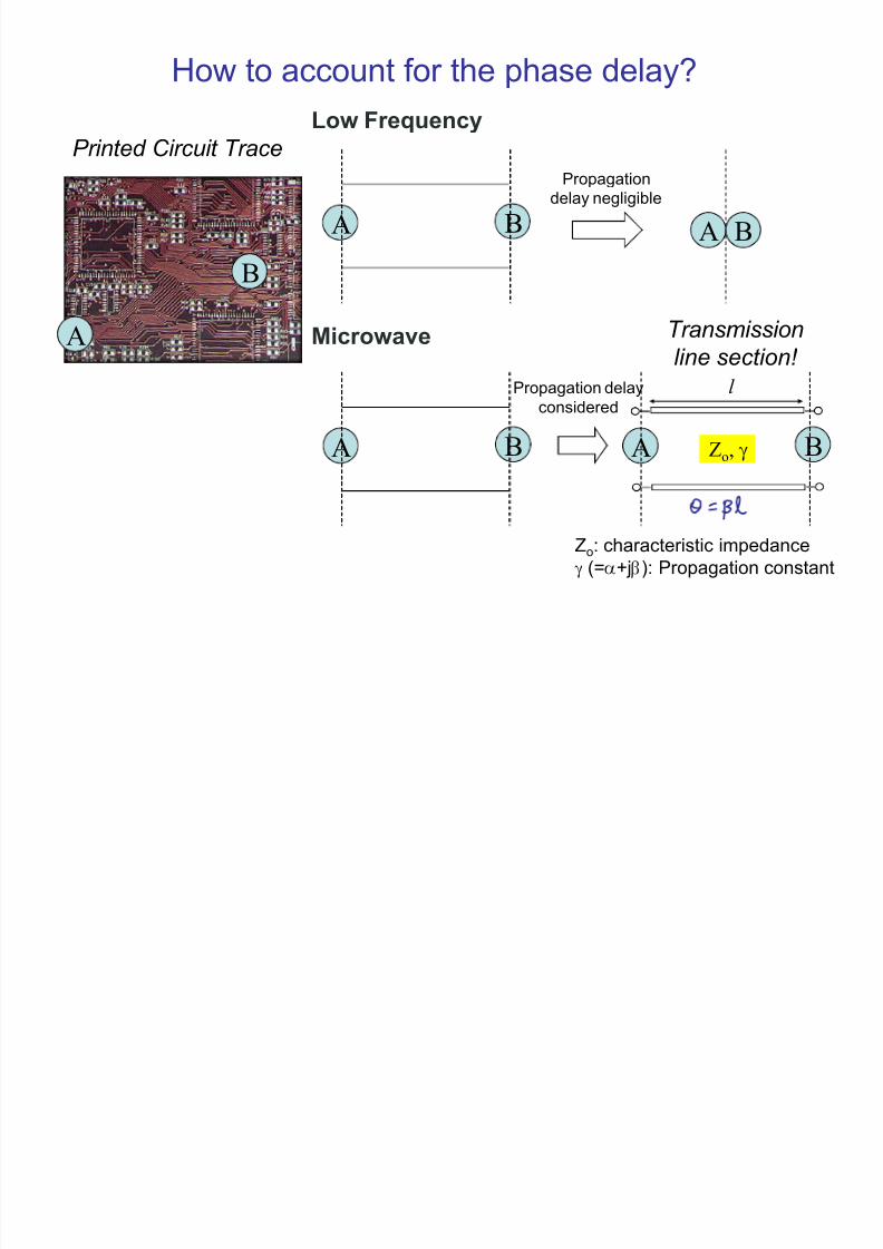
How to account for the phase delay?
A
B
A B
A B
Low Frequency
Microwave
A B
A B
Propagation
delay negligible
Transmission
line section!
l
P rinted Circuit Trace
Zo: characteristic impedance
K (=E+j F): Propagation constant
Zo, K
Propagation delay
considered

8/3/2019 Microwave Engineering Microwave Networks What Are Microwaves 589
http://slidepdf.com/reader/full/microwave-engineering-microwave-networks-what-are-microwaves-589 6/26
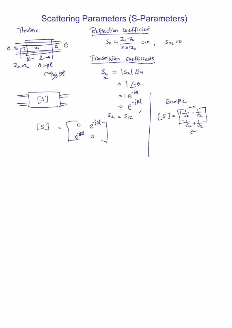
Scattering Parameters (S-Parameters)
Consider a circuit or device inserted into a
T-Line as shown in the Figure. We canrefer to this circuit or device as a two-port
network.
The behavior of the network can be
completely characterized by its scattering
parameters (S-parameters), or its
scattering matrix, [S].
Scattering matrices are frequently used to
characterize multiport networks, especially
at high frequencies. They are used to
represent microwave devices, such as
amplifiers and circulators, and are easilyrelated to concepts of gain, loss and
reflection.
? A11 12
21 22
S S S
S S
« »! ¬ ¼
- ½
Scattering matrix
8/3/2019 Microwave Engineering Microwave Networks What Are Microwaves 589
http://slidepdf.com/reader/full/microwave-engineering-microwave-networks-what-are-microwaves-589 7/26
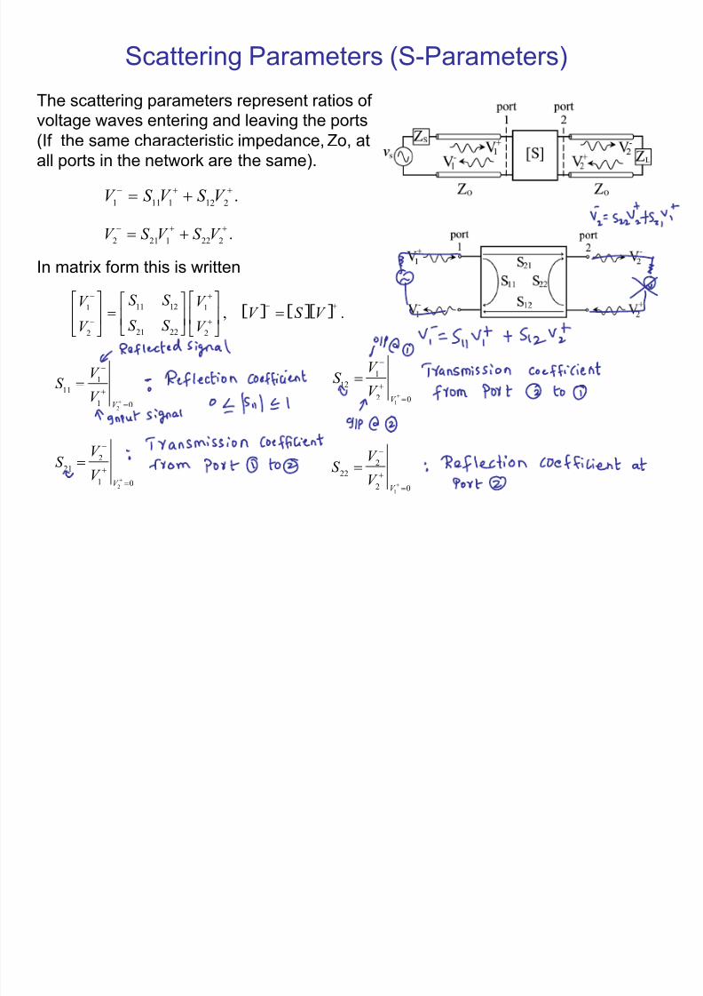
Scattering Parameters (S-Parameters)
The scattering parameters represent ratios of
voltage waves entering and leaving the ports(If the same characteristic impedance, Zo, at
all ports in the network are the same).
1 11 1 12 2.V S V S V
!
2 21 1 22 2.V S V S V
!
11 121 1
21 222 2
,S S V V
S S V V
!
« » « »« »¬ ¼ ¬ ¼¬ ¼
- ½- ½ - ½
In matrix form this is written
? A ? A? A .V S V
!
2
1
11
1 0V
V S
V
!
!1
1
12
2 0V
V S V
!
!
1
2
22
2
0V
V S
V
!
!2
2
21
1 0V
V S
V
!
!
8/3/2019 Microwave Engineering Microwave Networks What Are Microwaves 589
http://slidepdf.com/reader/full/microwave-engineering-microwave-networks-what-are-microwaves-589 8/26
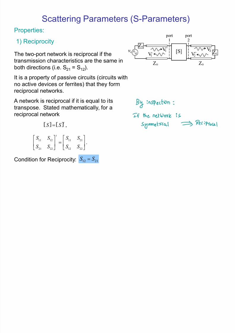
Scattering Parameters (S-Parameters)
Properties:
The two-port network is reciprocal if the
transmission characteristics are the same in
both directions (i.e. S21 = S12).
It is a property of passive circuits (circuits with
no active devices or ferrites) that they formreciprocal networks.
A network is reciprocal if it is equal to its
transpose. Stated mathematically, for a
reciprocal network
? A ? A ,t S S !
11 12 11 21
21 22 12 22
.
t
S S S S
S S S S !
« » « »¬ ¼ ¬ ¼- ½ - ½
12 21S S !Condition for Reciprocity:
1) Reciprocity

8/3/2019 Microwave Engineering Microwave Networks What Are Microwaves 589
http://slidepdf.com/reader/full/microwave-engineering-microwave-networks-what-are-microwaves-589 9/26
Scattering Parameters (S-Parameters)
Properties:
A lossless network does not contain any resistive
elements and there is no attenuation of the signal.
No real power is delivered to the network.
Consequently, for any passive lossless network,
what goes in must come out!
In terms of scattering parameters, a network is
lossless if
2) Lossless Networks
? A ? A ? A*
,t
S S U !
1 0[ ] .
0 1U !
« »¬ ¼- ½
where [U ] is the unitary matrix
For a 2-port network, the product of the transpose matrix and the complex conjugate
matrix yields
? A ? A
2 2 * *
11 21 11 12 21 22*
2 2* *
12 11 22 21 12 22
1 0
0 1
t
S S S S S S
S S
S S S S S S
!
« »« »¬ ¼ ! ¬ ¼¬ ¼ - ½
- ½
2 2
11 211S S !
If the network is reciprocal and lossless* *
11 12 21 22 0S S S S !

8/3/2019 Microwave Engineering Microwave Networks What Are Microwaves 589
http://slidepdf.com/reader/full/microwave-engineering-microwave-networks-what-are-microwaves-589 10/26
Scattering Parameters (S-Parameters)
Return Loss and Insertion Loss
Two port networks are commonly described by their
return loss and insertion loss. The return loss, RL,
at the ith port of a network is defined as
20log 20log .i
i i
i
V RL
V
! ! +
The insertion loss, IL, defines how much of a signal
is lost as it goes from a jth port to an ith port. In
other words, it is a measure of the attenuation
resulting from insertion of a network between a
source and a load.
20log .i
ij
j
V IL
V
!
8/3/2019 Microwave Engineering Microwave Networks What Are Microwaves 589
http://slidepdf.com/reader/full/microwave-engineering-microwave-networks-what-are-microwaves-589 11/26
Scattering Parameters (S-Parameters)
8/3/2019 Microwave Engineering Microwave Networks What Are Microwaves 589
http://slidepdf.com/reader/full/microwave-engineering-microwave-networks-what-are-microwaves-589 12/26
Scattering Parameters (S-Parameters)
8/3/2019 Microwave Engineering Microwave Networks What Are Microwaves 589
http://slidepdf.com/reader/full/microwave-engineering-microwave-networks-what-are-microwaves-589 13/26
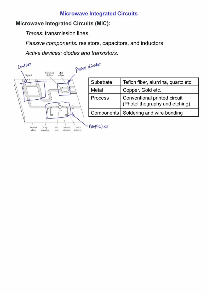
Microwave Integrated Circuits
Microwave Integrated Circuits (MIC):
Traces: transmission lines,
P assive components: resistors, capacitors, and inductors
Active devices: diodes and transistors.
Substrate Teflon fiber, alumina, quartz etc.
Metal Copper, Gold etc.
Process Conventional printed circuit
(Photolithography and etching)
Components Soldering and wire bonding

8/3/2019 Microwave Engineering Microwave Networks What Are Microwaves 589
http://slidepdf.com/reader/full/microwave-engineering-microwave-networks-what-are-microwaves-589 14/26
Lossless T-junction Power Divider
T-junction (Lossless divider)
PD 1.1
021
111
Z Z Z jBY
in!!
Input Matching Condition
0! B
021
111
Z Z Z !
o
o
in Z
V P
2
2
1!
1
2
12
1
Z
V P
o!2
2
2
2
1
Z
V P
o!
Input Power Output Power
in P P
3
11
!
in P P
3
2
2!
;! 50o
Z
;!! 15031 o
Z Z
;!! 752
32 o
Z Z
;!! 50||21 Z Z Z
in
Power Divider
EXAMPLE 7.1
2:1
Input Port is matched
Input Impedance
Ingoring the junction
reactance
;!! 30||21 Z Z Z
oin ;!! 5.37||12
Z Z Z oin
0!
!+
oin
oin
Z Z
Z Z
Output Ports are not matched
Input Port Output Port 1 Output Port 2
Reflection
Coefficient333.0
22
22
2!
!+
Z Z
Z Z
in
in666.011
111 !
!+
Z Z
Z Z
in
in
Power Divider
A T-junction power divider consists of one input port and two output ports.
Design Example
8/3/2019 Microwave Engineering Microwave Networks What Are Microwaves 589
http://slidepdf.com/reader/full/microwave-engineering-microwave-networks-what-are-microwaves-589 15/26
? A
¼¼¼¼
½
»
¬¬¬¬
-
«
!
00
0000
00
E F
E F FE
FE
S
? A
¼¼¼¼
½
»
¬¬¬¬
-
«
!
0
0
00
342414
342313
242312
141312
S S S
S S S
S S S S S S
S
? A
¼¼¼¼
½
»
¬¬¬¬
-
«
!
00
0000
00
E F
E F FE
FE
j
j j
j
S
Symmetric Coupler Antisymmetric Coupler
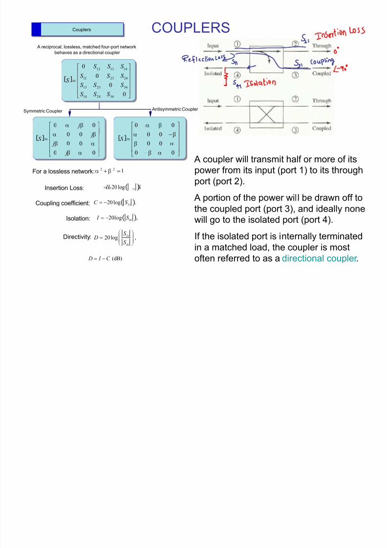
122 ! FE
A reciprocal, lossless, matched four-port network
behaves as a directional coupler
Couplers COUPLERS
A coupler will transmit half or more of its
power from its input (port 1) to its through
port (port 2).
A portion of the power will be drawn off to
the coupled port (port 3), and ideally none
will go to the isolated port (port 4).
If the isolated port is internally terminated
in a matched load, the coupler is most
often referred to as a directional coupler .
For a lossless network:
Coupling coefficient: 3120 log .C S !
21
20 log . IL S ! Insertion Loss:
4120log , I S ! Isolation:
31
41
20 log ,S
DS
!¨ ¸© ¹ª º
Directivity:
(dB) D I C !

8/3/2019 Microwave Engineering Microwave Networks What Are Microwaves 589
http://slidepdf.com/reader/full/microwave-engineering-microwave-networks-what-are-microwaves-589 16/26
COUPLERS
Design Example
Example 10.10: Suppose an antisymmetrical coupler has the following characteristics:
C = 10.0 dB
D = 15.0 dB
IL = 2.00 dB
VSWR = 1.30
Coupling coefficient: 3120 log .C S !
21
20 log . IL S ! Insertion Loss:
10/ 20
3110 0.316.S
! !
2 / 20
2110 0.794.S
! !
111 0.130.1
VSWRS VSWR
! !
25 , I D C d B! !25/ 20
4110 0.056.S
! !
VSWR = 1.30
? A
0.130 0.794 0.316 0.056
0.794 0.130 0.056 0.316
0.316 0.056 0.130 0.794
0.056 0.316 0.794 0.130
S
!
« »¬ ¼¬ ¼¬ ¼¬ ¼- ½
Given

8/3/2019 Microwave Engineering Microwave Networks What Are Microwaves 589
http://slidepdf.com/reader/full/microwave-engineering-microwave-networks-what-are-microwaves-589 17/26
COUPLERS
? A
0 1 1 0
1 0 0 1.
1 0 0 12
0 1 1 0
jS
!
« »¬ ¼¬ ¼¬ ¼¬ ¼- ½
? A
0 1 0
0 0 11
1 0 02
0 1 0
,
j
jS
j
j
!
« »¬ ¼¬ ¼¬ ¼¬ ¼- ½
The quadrature hybrid (or branch-line hybrid) isa 3 dB coupler. The quadrature term comes
from the 90 deg phase difference between the
outputs at ports 2 and 3.
The coupling and insertion loss are both equal
to 3 dB.
Ring hybrid (or rat-race) coupler Quadrature hybrid Coupler
A microwave signal fed at port 1 will split evenlyin both directions, giving identical signals out of
ports 2 and 3. But the split signals are 180 deg
out of phase at port 4, the isolated port, so they
cancel and no power exits port 4.
The insertion loss and coupling are both equal to
3 dB. Not only can the ring hybrid split power to
two ports, but it can add and subtract a pair of signals.

8/3/2019 Microwave Engineering Microwave Networks What Are Microwaves 589
http://slidepdf.com/reader/full/microwave-engineering-microwave-networks-what-are-microwaves-589 18/26
Filters
Filters are two-port networks used to attenuate undesirable frequencies.
Microwave filters are commonly used in transceiver circuits.
The four basic filter types are low-pass, high-pass, bandpass and bandstop.
Low-pass High-pass
BandstopBandpass

8/3/2019 Microwave Engineering Microwave Networks What Are Microwaves 589
http://slidepdf.com/reader/full/microwave-engineering-microwave-networks-what-are-microwaves-589 19/26
A low-pass filter is characterized by the insertion loss
versus frequency plot in Figure. Notice that there maybe ripple in the passband (the frequency range
desired to pass through the filter), and a roll off in
transmission above the cutoff or corner frequency, fc.
Simple filters (like series inductors or shunt capacitors)
feature 20 dB/decade roll off. Sharper roll off is
available using active filters or multisection filters.
Active filters employ operational amplifiers that are
limited by performance to the lower RF frequencies.
Multisection filters use passive components (inductors
and capacitors), to achieve filtering.
The two primary types are the Butterworth and the
Chebyshev. A Butterworth filter has no ripple in thepassband, while the Chebyshev filter features sharper
roll off.
FiltersLow-pass Filters

8/3/2019 Microwave Engineering Microwave Networks What Are Microwaves 589
http://slidepdf.com/reader/full/microwave-engineering-microwave-networks-what-are-microwaves-589 20/26
Low-pass Filters
High-pass Filters Band-pass Filters
Lumped Element Filters
Some simple lumped element filter circuits are shown below.
8/3/2019 Microwave Engineering Microwave Networks What Are Microwaves 589
http://slidepdf.com/reader/full/microwave-engineering-microwave-networks-what-are-microwaves-589 21/26
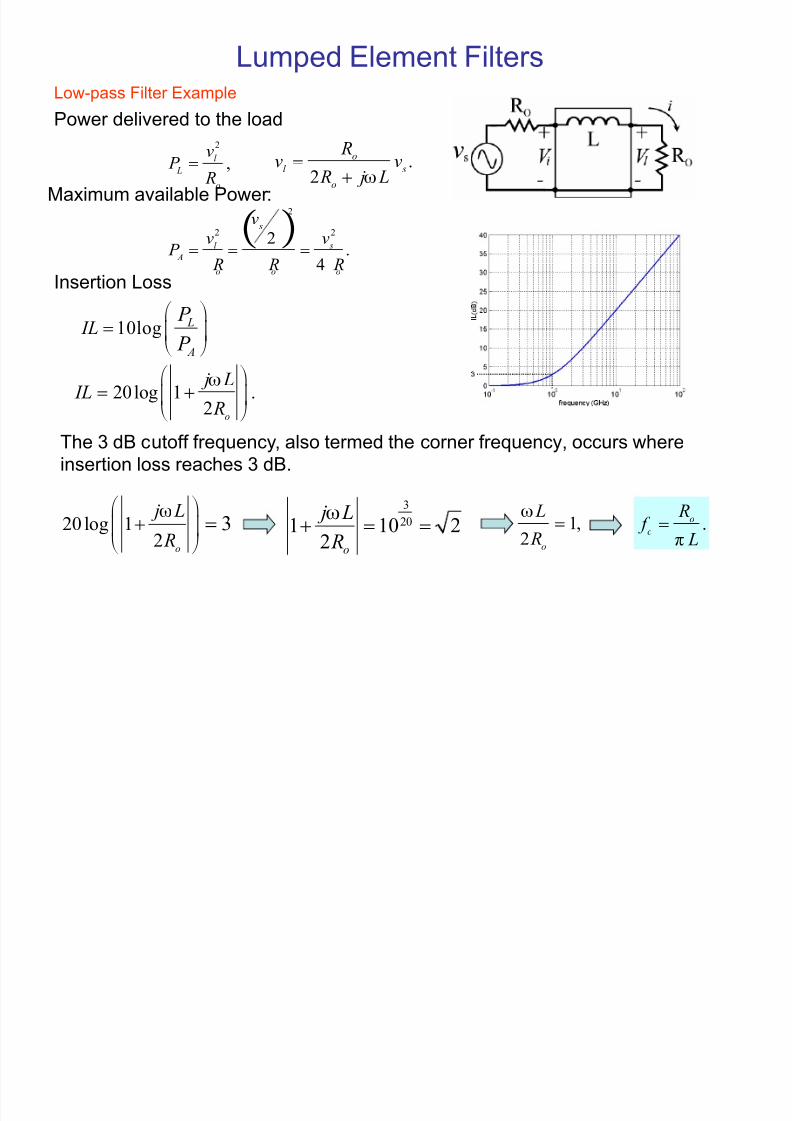
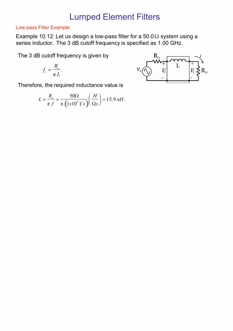
Low-pass Filter Example
Lumped Element Filters
2
,l
L
o
v P
R! .
2
o
l s
o
Rv v
R j L[!
20log 1 .2
o
j L IL
R
[
! ¨ ¸© ¹
ª ºThe 3 dB cutoff frequency, also termed the corner frequency, occurs where
insertion loss reaches 3 dB.
1,2
o
L
R
[
!20 log 12
3o
j L
R
[
¨ ¸
!© ¹
ª º
3
201 10 22
o
j L
R
[
! ! .o
c
R f
LT!
2
2 2
2.
4
s
l s
A
o o o
v
v v P
R R R! ! !
10log L
A
ILP
P !
¨ ¸© ¹ª º
Power delivered to the load
Insertion Loss
Maximum available Power :
8/3/2019 Microwave Engineering Microwave Networks What Are Microwaves 589
http://slidepdf.com/reader/full/microwave-engineering-microwave-networks-what-are-microwaves-589 22/26
Low-pass Filter Example
Example 10.12: Let us design a low-pass filter for a 50.0 ; system using a
series inductor. The 3 dB cutoff frequency is specified as 1.00 GHz.
Lumped Element Filters
.o
c
R f
LT!
The 3 dB cutoff frequency is given by
9
5015.9 .
1 10 1
o R H
L n H f s x sT T
;! ! !
;¨ ¸© ¹ª º
Therefore, the required inductance value is

8/3/2019 Microwave Engineering Microwave Networks What Are Microwaves 589
http://slidepdf.com/reader/full/microwave-engineering-microwave-networks-what-are-microwaves-589 23/26
Filters
The insertion loss for a bandpass filter is shown in
Figure. Here the passband ripple is desired small.The sharpness of the filter response is given by the
shape factor, SF, related to the filter bandwidth at 3dB
and 60dB by
60
3
.d B
d B
BW SF
BW
!
A filter¶s insertion loss relates the power delivered to
the load without the filter in place (PL) to the power
delivered with the filter in place (PLf):
10log .
L
Lf
P
IL P !
¨ ¸
© ¹ª º
Band-pass Filters

8/3/2019 Microwave Engineering Microwave Networks What Are Microwaves 589
http://slidepdf.com/reader/full/microwave-engineering-microwave-networks-what-are-microwaves-589 24/26
Amplifier Design
Microwave amplifiers are a common and crucial component of wireless transceivers.
They are constructed around a microwave transistor from the field effect transistor (FET) or bipolar junction transistor (BJT) families.
A general microwave amplifier can be represented by the 2-port S-matrix network
between a pair of impedance-matching networks as shown in the Figure below. The
matching networks are necessary to minimize reflections seen by the source and to
maximize power to the output.
8/3/2019 Microwave Engineering Microwave Networks What Are Microwaves 589
http://slidepdf.com/reader/full/microwave-engineering-microwave-networks-what-are-microwaves-589 25/26
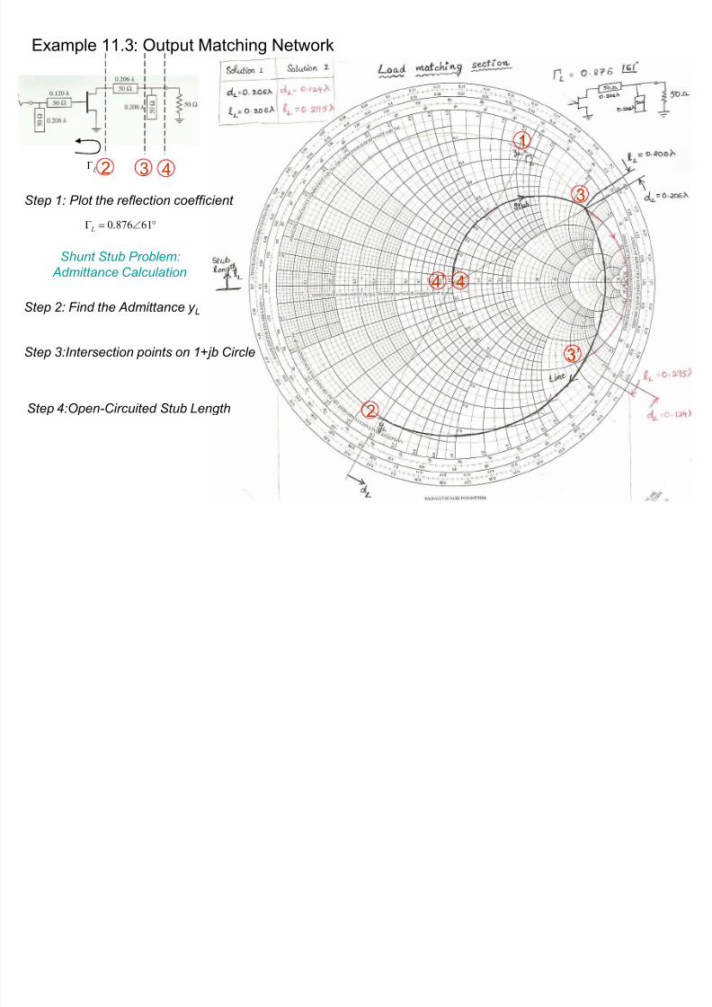
Example 11.3: Output Matching Network
S tep 1: P lot the reflection coefficient
S tep 3:Intersection points on 1+jb Circle
S tep 4:Open-Circuited S tub Length
S tep 2: Find the Admittance y L
S hunt S tub P roblem:
Admittance Calculation
r!+ 61876.0 L
L+
1
2
3
4
3
4
2 3 4
8/3/2019 Microwave Engineering Microwave Networks What Are Microwaves 589
http://slidepdf.com/reader/full/microwave-engineering-microwave-networks-what-are-microwaves-589 26/26
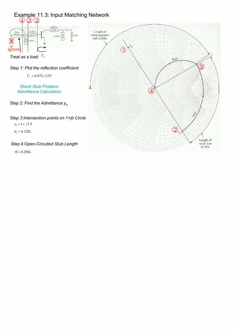
Example 11.3: Input Matching Network
S tep 1: P lot the reflection coefficient
S tep 3:Intersection points on 1+jb Circle
S tep 4:Open-Circuited S tub Length
S tep 2: Find the Admittance y s
1
2
3
4S hunt S tub P roblem:
Admittance Calculation
P120.01 !d
5.311 j y !
P206.01 !N
r!+ 123872.0 s
S +
XIgnore
Treat as a load
234