Embed Size (px)
Citation preview

LOGOSMicrowave Hybrid Tissue Processor
Operator ManualMM082-002 (June 2012)
MILESTONEH E L P I N GP A T I E N T S


Milestone s.r.l. MM082-002 – LOGOS – Operation Manual
Page 3 of 112
Thank you for having selected our system and welcome to the ever growing world club of users for Milestone laboratory instrumentation. We are sure that you will be completely satisfied with this new tool entering your laboratory. We invite you to read carefully this operator manual and to keep it in reach for convenient and fast consulting. For any possible clarification or any request for assistance please contact either our Representative in your country: Or contact Milestone s.r.l. Via Fatebenefratelli, 1/5 24010 Sorisole (BG) Italy Tel. +39.035.412 8264 Fax +39.035.575498 web site www.milestonemedsrl.com e-mail [email protected]
Please read the user manual before using the device .

Milestone s.r.l. MM082-002 – LOGOS – Operation Manual
Page 4 of 112
INDEX
1 INTRODUCTION.........................................................................................................6
1.1 SYMBOLS USED IN THIS MANUAL ............................................................................................... 6 1.2 DESIGNATED USES ....................................................................................................................... 7 1.3 TECHNICAL SPECIFICATIONS...................................................................................................... 7
1.3.1 Touch control terminal ............................................................................................................. 8 1.4 TRANSPORTATION AND STORAGE CONDITIONS ..................................................................... 8 1.5 WARNING INFORMATION.............................................................................................................. 9 1.6 INSTRUMENT LABELING EXPLANATION................................................................................... 10 1.7 COMPATIBLE REAGENTS ........................................................................................................... 10 1.8 WASTE DISPOSAL OF THE EQUIPMENT................................................................................... 11
2 SETTING UP THE INSTRUMENT ............................................................................12 2.1 SPACE REQUIREMENTS ............................................................................................................. 12 2.2 UNPACKING AND CHECKING LIST............................................................................................. 13 2.3 POWER SUPPLY........................................................................................................................... 14 2.4 FUMES EXTRACTION SYSTEM................................................................................................... 14 2.5 ELECTRICAL INSTALLATION OF LOGOS................................................................................... 15
2.5.1 Back side connection plate 115V Version ............................................................................. 15 2.5.2 Back side connection plate 230V Version ............................................................................. 16 2.5.3 Main power supply connection .............................................................................................. 16 2.5.4 Power supply connection (NO UPS mode) ........................................................................... 17 2.5.5 Power supply connection (Local UPS mode) ........................................................................ 18
2.6 REMOTE ALARM CONNECTION ................................................................................................. 19 2.6.1 Luminous tower (optional, Ref. P/N 61540, not included to be ordered apart) ..................... 19
2.7 INTERNET CONNECTION ............................................................................................................ 21 2.8 FINAL PLACEMENT ...................................................................................................................... 23 2.9 REAGENTS.................................................................................................................................... 23 2.10 LOG IN AND LOG OUT ................................................................................................................. 24 2.11 SET SYSTEM DATE AND TIME.................................................................................................... 27 2.12 SET LANGUAGE ........................................................................................................................... 28 2.13 LOAD LOGOS WITH WAX ............................................................................................................ 29 2.14 HOW TO LOAD LOGOS WITH REAGENTS................................................................................. 32
2.14.1 Cleaning procedure for Cleaning Tanks................................................................................ 32 2.14.2 How to set up LOGOS with reagents .................................................................................... 33
2.15 MOST USED PROGRAMS............................................................................................................ 38 2.16 OWNER SETTINGS....................................................................................................................... 40
3 OPERATE WITH LOGOS .........................................................................................43 3.1 LOADING CASSETTES INTO THE SPLIT RACK......................................................................... 43 3.2 RUN A PROGRAM......................................................................................................................... 44
3.2.1 Run of the most used program.............................................................................................. 44 3.2.2 Run a standard program........................................................................................................ 50 3.2.3 Run two processes simultaneously ....................................................................................... 52 3.2.4 Run a program using the STEP START function .................................................................. 54 3.2.5 Run a DELAYED PROGRAM................................................................................................ 54
3.2.5.1 Add Extra Cassettes during the delayed start .............................................................. 56 3.3 RUN A CLEANING CYCLE OF THE MAIN CAVITY ..................................................................... 57 3.4 RETRIEVING SAVED PROCESSING RESULTS ......................................................................... 59
3.4.1 How to delete a saved processing......................................................................................... 60 3.5 HOW TO MODIFY A PROGRAM .................................................................................................. 61
3.5.1 How to modify a cleaning program........................................................................................ 62 4 REAGENTS MANAGEMENT ....................................................................................63
4.1 REAGENT REUSE LIFE................................................................................................................ 64 4.1.1 Reagent settings.................................................................................................................... 64 4.1.2 Recommendation for reuse life.............................................................................................. 66
4.2 REAGENT REPLACEMENT PROCEDURE.................................................................................. 67 4.3 WAX REPLACEMENT ................................................................................................................... 70
5 POWER FAILURE MANAGEMENT ..........................................................................72 5.1 EXTERNAL POWER SUPPLY ...................................................................................................... 72 5.2 WHAT HAPPENS DURING POWER FAILURE? .......................................................................... 73

Milestone s.r.l. MM082-002 – LOGOS – Operation Manual
Page 5 of 112
6 LOADING TIME-OUT MANAGEMENT .....................................................................75 6.1 SAFETY MODE PROCEDURE (after 20 minutes) ........................................................................ 75
7 MAINTENANCE ........................................................................................................77 7.1 INTRODUCTION............................................................................................................................ 77 7.2 AFTER EACH RUN........................................................................................................................ 77
7.2.1 Rack cleaning procedure....................................................................................................... 77 7.3 DAILY ............................................................................................................................................. 79 7.4 TWICE A WEEK............................................................................................................................. 79
7.4.1 Wax cleaning ......................................................................................................................... 79 7.5 WEEKLY......................................................................................................................................... 81 7.6 YEARLY ......................................................................................................................................... 81 7.7 HOW TO START THE REMOTE ASSISTANCE ........................................................................... 82
8 GOOD TISSUE PROCESSING PRACTICE..............................................................83 8.1 MICROWAVE ALCOHOLS QUALITY............................................................................................ 85 8.2 TISSUE PROCESSING SELECTION GUIDELINES..................................................................... 86
9 REPORTING.............................................................................................................88 9.1 EXPORT PROCESSINGS FROM THE TERMINAL TO THE USB KEY....................................... 88 9.2 INSTALL AND OPERATE WITH THE LOGVIEWER .................................................................... 89
9.2.1 Open process ........................................................................................................................ 89 9.2.2 Print process.......................................................................................................................... 91 9.2.3 Send process to customer support (Milestone)..................................................................... 92 9.2.4 Change settings..................................................................................................................... 93 9.2.5 Other functions ...................................................................................................................... 93
10 LOGOS OPTIONAL ACCESSORIES........................................................................94 A. APPENDIX ................................................................................................................97
A.1. MW TISSUE PROCESSING TROUBLESHOOTING GUIDE ........................................................ 97 A.2. OVERVIEW OF MICROWAVE HISTOPROCESSING TROUBLE SHOOTING.......................... 104
B. APPENDIX ..............................................................................................................105 B.1. HOW TO MANAGE AN ALARM .................................................................................................. 105
C. APPENDIX ..............................................................................................................107 C.1. HOW TO MANAGE SAMPLES WHILE AN ALARM IS OCCURRING ........................................ 107

Milestone s.r.l. MM082-002 – LOGOS – Operation Manual
Page 6 of 112
1 INTRODUCTION
1.1 SYMBOLS USED IN THIS MANUAL
An instruction accompanied by this symbol provides a cautionary statement: WARNING. Failure to follow the instruction may enda nger the USER or cause damage to the instrument.
An instruction accompanied by this symbol provides a caution against electric shock. Be sure to follow the instruction to prevent accide nts resulting from electric shock.
Biohazard.
Surface at danger temperature (more than 70°C, 158° F) do not touch.
Potentially flammable.
CE logo: this instrument complies with European com munity directives.
IVD medical device according to 98/79/EC directive.
Please read carefully this instruction.
Please read SERVICE Manual (operation for SERVICE o nly).
WEEE European directive symbol (2002/96/EC). Electric/electronic device do not throw out in the environment.
The Reagents/WAX are suitable for use.
The Reagents/WAX are near expiration.
The Reagents/WAX are expired and need to be substit uted.

Milestone s.r.l. MM082-002 – LOGOS – Operation Manual
Page 7 of 112
1.2 DESIGNATED USES
The Milestone LOGOS and its accessories have been engineered for laboratory use and can therefore withstand the harshest laboratory conditions for continuous use in Histological sample preparation procedures. The instrument is intended for laboratory use (indoor use) only . The Milestone LOGOS is specifically designed to automatically (when an automatic run is selected) or semi-automatically (when a dual run is selected) execute these processes for histopathological applications:
• Fixation, Post-fixation
• Dehydration and Clearing
• Drying
• Paraffin wax infiltration
The Milestone LOGOS must be operated exclusively with the reagents listed in section “Compatible reagents ” 1.7.
Any other use of the instrument is considered impro per and may void the warranty provided by the manufacturer.
1.3 TECHNICAL SPECIFICATIONS
Ref. P/N 61502: Power supply input: 115V~ 60Hz 2300W,
Ref. P/N 61500: Power supply input: 230V~ 50Hz 2300W,
Ref. P/N 61501: Power supply input: 230V~ 60Hz 2300W.
Working Temperature: 15°C – 30°C (59°F – 86°F)
Humidity (relative): up to 80%
Maximum altitude: 2000m
Fan air flow range: 54–58m3/h (cube meter per hour).
Indoor use only.
This unit is developed to comply with the CAP-College of American Pathologists checklist of requirements for microwave instruments.

Milestone s.r.l. MM082-002 – LOGOS – Operation Manual
Page 8 of 112
1.3.1 Touch control terminal The following picture shows the Touch Control TERMINAL of the LOGOS unit. It is possible to operate the unit by simply touching the icons on the screen.
Two USB PORTS are located on the right side of the Touch Control Terminal.
Characteristics: TK-WIN10CEi-TFT-LCD color display Resolution 800x600 pixels, 8’’ Touch screen Mass storage CF 256MB RAM 256 MB CPU 500MHz Windows™ CE.NET 6.0 Programs: Multiple pre-stored programs, with customizable user defined programs. I/O-Interface: 2x USB port 2.0, 1x LAN Ethernet 10/100 Mbps RJ-45.
1.4 TRANSPORTATION AND STORAGE CONDITIONS Temperature: –20°C up to +60°C
Humidity: up to 50% (at 40°C) non–condensing
Before turning LOGOS on (when coming from a storage room), let the unit reach working environmental conditions (at least half an hour).
The manufacturer reserves the right to change and/o r improve specifications without notice and without incurring any obligation.

Milestone s.r.l. MM082-002 – LOGOS – Operation Manual
Page 9 of 112
1.5 WARNING INFORMATION Should the equipment be used in different ways than those specified by the manufacturer, the warranty provided by the manufacturer may be void.
Main power plugs are considered disconnecting device. Disconnect all plugs from the socket outlet before assembling of the system, before connection of the accessories and before cleaning.
Equipment shall be connected to a main power socket outlet which is accessible and visible by the operator.
Equipment is provided with replaceable fuses, however their replacement is to be performed by properly authorized service personnel. If the system is not properly working, please contact the local authorized and trained service representative of the manufacturer.
All parts of the equipment and all accessories must be supplied only by the manufacturer.
DO NOT OPEN THE CHASSIS. Failure to follow the inst ruction in the documentation might lead to a reduction of device safety. If the equipment is not working properly,
please contact your supplier or the manufacturer.
Do not remove the instrument, accessories, panels o r cover. Only authorized and
qualified SERVICE personnel may repair the instrume nt and access the instrument’s internal components.
It is important that normal standards for safety an d good laboratory practices are
applied. Always use common sense and the best known practice when operating the instrument. Failure to follow the instructions in t he documentation might lead to a
reduction of device safety. The Competent Authority owning the instrument has p rimary responsibility for
accident-free operation together with designated pe rsonnel who operates SERVICE or repair it.
To avoid damage to the instrument, use only the rea gents listed in section 1.7
Compatible Reagents. Failure to follow the instruct ions in the documentation might lead to a reduction of device safety.
Use caution when handling hot, molten WAX.
METAL PARTS
Never introduce metal parts into the MAIN CAVITY. High voltage discharges may cause uncontrolled incr eases of temperature, which
could damage the unit and result in incorrect tissu e processing also. Failure to follow the instructions in the documentation might lead to a reduction of device
safety.
Be careful: exhaust reagents are toxic and carcinog enic.
Handle with care and follow the local standard regu lations.

Milestone s.r.l. MM082-002 – LOGOS – Operation Manual
Page 10 of 112
1.6 INSTRUMENT LABELING EXPLANATION
For symbols explanation see Chapter 1.1.
1.7 COMPATIBLE REAGENTS
Fixatives
1. Milestone Finefix® 2. Formalin, buffered or unbuffered
Holding
1. PBS buffer 2. Alcohol/water (70/30) solution
Dehydration – Clearing
1. Milestone JFC® solution 2. Milestone Prowave® solution 3. Ethanol 4. Isopropanol 5. Xylene
Impregnation
1. Paraffin, Histology grade Other
1. Alcohol/water (60/40) solution (Flushing)
Please refer to chapter 8.1 for purity grade of rea gents.
DO NOT USE REAGENTS DIFFERENT FROM THOSE LISTED ABO VE. In case of doubts please contact: [email protected] .
Reagents other than those listed above may damage s ome components of the instrument. Do not use acetone, benzene or trichlorethane in th e instrument.

Milestone s.r.l. MM082-002 – LOGOS – Operation Manual
Page 11 of 112
1.8 WASTE DISPOSAL OF THE EQUIPMENT This instrument is an in-vitro medical device and it is usually installed in a laboratory where specimens and other biological tissues are present. For your safety, it is therefore required to clean and disinfect before entering in contact with it. You must also wear gloves when operating the system. In case of return it is required that the unit is cleaned and disinfected before sending it back to Milestone. Non-disinfected devices will be no longer accepted and you will be contacted to pay the relative disinfection cost. International health rules require that shipments of biohazard materials are not done in standard packages (risk of sanctions).
It is recommended to use enzymatic detergents and polyphenolic based disinfectants or chlorine substitutes to clean and disinfect the instrument. In alternative, to decontaminate the instrument, the use of a solution of 1:10 Bleach (recommended by the CDC for disinfecting) is also allowed. For further information, please contact the manufacturer: [email protected] . In addition, complying with directive 2002/96/EC of the European Parliament and of the Council of 27 January 2003 on waste electrical and electronic equipment (WEEE), the separate collection environmental managed of equipment is mandatory. It is necessary to return the used equipment to the distributor or to inquire about the presence of a local empowered system for collection and disposal of WEEE. The in-observance of Directive 2002/96/EC or of the local law which acknowledges it can have potential effects on the environment and human health.
This symbol indicates separate collection for electrical and electronic equipment
If additional requirements on accident prevention and environmental protection exist in the country of operation, this instruction manual must be supplemented by appropriate instructions to ensure compliance to such requirements. Waste disposal of reagents
For further information please refer to the MSDS (Material Data Safety Sheet) provided by your supplier.
Do not remove the side panels of the unit during th e cleaning operations.
Before doing any operation disconnect the power sup ply. Do not use direct or high-pressure water to clean t he instrument.
For safety reason, any operation without the indivi dual protective devices must be avoided.
Handle with care and store in a cool dry space using a tig htly closed container. Vapors may collect in empty containers. Treat empty containers as hazardous.
Waste material should be disposed of in an approved incinerator or in a designated landfill site, in compliance with all federal, provincial an d local government regulations.
Some reagents can have potential health effects and cause environmental pollution if not correctly disposed.

Milestone s.r.l. MM082-002 – LOGOS – Operation Manual
Page 12 of 112
2 SETTING UP THE INSTRUMENT Milestone LOGOS is a precision instrument that requires the utmost care when it is unpacked and installed. Move LOGOS to its final location. Make sure that the floor is level and is made of non-flammable material. The following pictures show the dimensions of LOGOS and the space required:
2.1 SPACE REQUIREMENTS LOGOS is delivered in a wood box with these dimensions:
Width: 920mm 36.2in (minimum) Height: 1320mm 52in Depth: 1500mm 59.1in,
The space dimensions required to locate the unit are the following (drawer and covers opened):
Width: 1100mm, Height: 1600mm, Depth: 1200mm
Logos is a heavy instrument. Contact a structural engineer before placing the unit (analyze the building structure). LOGOS Weight (read carefully) :
LOGOS FULL (all tanks): 320kg (706lb) (wax and all reagents loaded in proper tanks).
LOGOS EMPTY: 250kg (552lb) (no reagents; no Paraffi n Wax histological grade)
Unit density 640kg/m 2 (0.9lb/in 2).
1500mm
1090mm
695mm 760mm

Milestone s.r.l. MM082-002 – LOGOS – Operation Manual
Page 13 of 112
2.2 UNPACKING AND CHECKING LIST When unpacking, check that all parts correspond to the packing list included in the shipment. Utmost care must be made during unpacking of LOGOS, to avoid any scratch or damage to the external coating (acid/organic solvent resistant). The Starter Kit LOGOS (Ref. P/N 61503) includes the following items:
1. n° 1 Rack Transfer Kit (Ref. P/N 66105),
2. n°2 Split Rack 210 cassettes (Ref. P/N 66165),
3. n°1 Antiscratching Spatula to remove wax traces (Ref. P/N 62348),
4. n° 1 USB Data Traveler (Ref. P/N 62160) containi ng the LogViewer Software (see the chapter 9.2),
5. n° 1 Exhaust Tube complete (Ref. P/N 61597).

Milestone s.r.l. MM082-002 – LOGOS – Operation Manual
Page 14 of 112
2.3 POWER SUPPLY Power supply line must have a ground connection (yellow/green, green or bare wire). Do not use the blue/white wire (neutral of power line). Power supply neutral has to be referred to ground.
Carefully check that:
• A strong Ground Connection is made available in the lab to assure the unit works correctly. Do not connect a Milestone unit without ground connection.
• A Dedicated ground Connection , direct from the main electric box (cabinet) of the laboratory to our unit is ideal to eliminate any possible interference/electronic noise originated by other instruments supplied with the same line.
• Power supply line wires (their size and distance from the switch board) used in the laboratory are compliant with the label positioned on the back side of our units.
• Plug/socket is visible during the normal use and easily accessible. Power line protection: o 115V: Miniature circuit breaker curve C, 20A, interruption more than 6000A. o 230V: Miniature circuit breaker curve C, 16A, interruption more than 6000A.
Residual current device: 30mA (Class I device).
Only 230V version: a schuko terminated power cord is provided. The 115V version is not terminated.
2.4 FUMES EXTRACTION SYSTEM
LOGOS is vented, to comply with CAP regulations, through the external exhaust outlet positioned on the back of the instrument, with a hose dedicated to the external fume extraction system (if any).
The customer is required to adapt the hose connector. The plastic hose supplied has these characteristics: • Length: 3m (110”) • External diameter: 69mm (2.72”) • Internal diameter: 60mm (2.36”)
Insert the exhaust tube (Ref. P/N 61377) on the proper outlet (backpanel).
The external fume extraction system must be properl y installed at all times, according to local regulations in force on laboratory safety.
The external fume extraction system must permit an air flux of 58 m 3/h (cube meter per hour).
There is no air filter on the unit exhaust system.
It is possible to connect an external exhaust fumes filter kit. See chapter 10 for information about this optional (Ref. P/N 61550).

Milestone s.r.l. MM082-002 – LOGOS – Operation Manual
Page 15 of 112
Use the metal cable clamp to fix the hose to the exhaust fume pipeline.
Now connect the other side of tube to the fume extractor of the laboratory.
2.5 ELECTRICAL INSTALLATION OF LOGOS
Before connecting the plug to the laboratory’s sock et CHECK that the power supply voltage of the unit matches the power supply line o f the laboratory.
Damages occur when wrong power supplies the instrum ent.
2.5.1 Back side connection plate 115V Version On the back side of the LOGOS are positioned the connection plates:
Descriptions:
1. Speaker 2. Remote/external alarm connector 3. Ethernet/ LAN plug 4. UPS side supply (controller power supply input) 5. UPS supplier socket (energy output to local ups unit) 6. Main power supply
See also the Label of the instrument that provides some important information. Always communicate the S.N. of the unit to Customer Support.
P/N 50051
1 2
3 6
5 4

Milestone s.r.l. MM082-002 – LOGOS – Operation Manual
Page 16 of 112
2.5.2 Back side connection plate 230V Version On the back side of the LOGOS are positioned the connection plates:
Descriptions:
1. Speaker 2. Remote/external alarm connector 3. Ethernet/ LAN plug 4. UPS side supply (controller power supply input), 5. UPS supplier socket (energy output to local ups unit), 6. Main power supply
2.5.3 Main power supply connection ONLY FOR 115V VERSION, add plug to the cable:
Connect the two black wires to power pins of the plug and the yellow/green to ground’s pin. Diameter approx 10mm, size of wires AWG12.
As separable power cord, it is strictly required to use power cord with wire size at least of 1.5mm² (equal to minimum AWG12). A size less of 1.5 mm² (AWG12) cannot guarantee a
proper functionality of the unit and over heating o f the power cord.
See also the Label of the instrument that provides some important information. Always communicate the S.N. of the unit to Customer Support.
NEVER DIRECTLY CONNECT LOGOS TO THE SWITCHBOARD. IT IS REQUIRED TO USE A SEPARABLE PLUG, WITHOUT A L OCKING DEVICE to mate
with the socket-outlet in the laboratory .
12
3
45
6

Milestone s.r.l. MM082-002 – LOGOS – Operation Manual
Page 17 of 112
ONLY FOR 230V VERSION, connect the cable Ref. P/N 70304 to connector 1 (see the chapter 2.5.2).
2.5.4 Power supply connection (NO UPS mode) There are two ways to connect the LOGOS to power supply line. Characteristic: This is the easier way to supply the LOGOS, but it does NOT protect the unit from power supply failure. In fact, in case of power failure, user cannot remo ve samples from LOGOS nor do any other operations . For this reason, Milestone s.r.l. does NOT suggest this type of connection. Make sure to inform the customer that in this way a power supply failure inhibits any operation with LOGOS.
Connect the by-pass cable (Ref. P/N 66643) from (5) UPS supplier socket to (4) UPS side supply. Then connect the socket to main power supply (6): now it is possible to turn the LOGOS “ON”.
Do not connect UPS supplier socket (4) directly to the laboratory socket power supply: this input power supply complies to CISPR 11 class A and may cause electromagnetic
interference to other devices.
As separable power cord, it is strictly required to use power cord with wire size at least of 1.5mm² (equal to minimum AWG12). A size less of 1.5 mm² (AWG12) cannot guarantee a
proper functionality of the unit and over heating o f the power cord.

Milestone s.r.l. MM082-002 – LOGOS – Operation Manual
Page 18 of 112
2.5.5 Power supply connection (Local UPS mode)
Characteristic: Milestone s.r.l. strongly recommends this type of connection as it protects the LOGOS from power supply failure. In this case, in fact, LOGOS cannot process, but can execute all other procedures. In fact “UPS side supply” provides energy at logic circuits.
Even when Logos is directly plugged into the main hospital UPS line or power emergency line, we observed occurring of delays or discontinuity of a few seconds/ minutes of the power supply. In this case, Logos stops working and the standard power failure procedure, that puts tissues in safety, is not activated. For this reason, we highly recommend to install a UPS module on any Logos unit.
Milestone can supply only UPS at 230Volt-50/60Hz (Ref. P/N 66100) with the following technical specifications: 230V version (Ref. P/N66100)
• Voltage input 230V 50/60Hz according to your power supply • Power 1000VA/600W (minimum) • Capacity 15 minutes @ 500W (minimum) • Output 230V±10% 50/60±1Hz • Transfer time 6ms (max) • With cord set for connections • DxWxH 405x205x145mm (if provided locally: footprint max 190×600mm) • Weight: 9.6 kg (if provided locally: max 20kg - 44lb)
UPS unit at 115Volt-60Hz must be provided locally with the following minimum technical specifications:
115V version • Voltage input 115V 60Hz according to your power supply • Power 1000VA/600W (minimum) • Capacity 15 minutes @ 500W (minimum) • Output 230V±10% 60±1Hz • Transfer time 6ms (max) • With cord set for connections • Footprint max 190×600 mm • Weight max 20kg (44lb)
Connect the “UPS supplier socket” (connector type IEC320–C13), (refer to figure below) to the UPS power input. Maximum current 4A (230V), frequency same as local (refer to figure below-A). Connect the UPS power output to the “UPS side supply” (connector type IEC320-C14) (refer to figure below-B).
Wrong connections of UPS prejudice the functionalit y of safety procedures detailed in the chapter 5.
B
A

Milestone s.r.l. MM082-002 – LOGOS – Operation Manual
Page 19 of 112
Then connect the plug of main power supply to socket: now it is possible to turn the LOGOS “ON”.
2.6 REMOTE ALARM CONNECTION LOGOS is also provided with two auxiliary outputs in order to connect external devices:
It is possible to connect a luminous tower. See details on this option in the chapters 2.6.1 and 10.
2.6.1 Luminous tower (optional, Ref. P/N 61540, not included to be ordered apart) See details on the parts of this option in chapter 10. 1. Screw the luminous tower to the chassis of the unit:
1
2. Remove the green connector provided with the unit by unscrewing anticlockwise the two screws. 3. Replace with the connector supplied with the luminous tower then retighten the two screws.
2 3
Output Contact Status 1 Normally CLOSED 2 Normally OPEN
1 Identifies the LOGOS alarm switch
3 COMMON 7 Normally OPEN 2
Identifies the LOGOS end program 8 COMMON
For safety reasons and for preventing any damage to the internal relays, any external devices that need to be connected to LOGOS unit mus t have a maximum Voltage lower
than 40 VDC – 1A.

Milestone s.r.l. MM082-002 – LOGOS – Operation Manual
Page 20 of 112
4. Insert the power supply plug into the luminous tower box socket.
4
5. Insert the main plug in the power supply (A) and then the cable plug in a main socket (B).
5A 5B
6. It is also possible to connect the luminous tower with the UPS, in this case use the cable E (for details of connection see chapter 2.5.5). Squares and connections: yellow to luminous tower, blue to UPS.
Final view of the unit with luminous tower mounted on the back.

Milestone s.r.l. MM082-002 – LOGOS – Operation Manual
Page 21 of 112
2.7 INTERNET CONNECTION
It is necessary to connect LOGOS to Internet to get Remote Assistance services.
IT IS NOT ADVISED TO RUN PROGRAMS WITH LOGOS WHILE USING THE REMOTE ASSISTANCE CONNECTION.
PROCESSES IN REMOTE ASSISTANCE ARE FOR TESTING USE ONLY, NEVER PLACE SPECIMENS INSIDE LOGOS.
In order to access the remote assistance (as described in the chapter 7.7), you need to get the following data from the Information Technology Department/Network Administrator of the customer: - LAN connection with standard RJ45 Ethernet cable and connector, - Dedicated IP address and Subnet Mask (strongly preferred to DHCP service); only port 80 has to be
enabled without limitations, - LAN gateway and DNS server addresses, - At least 150kb/s real transfer rate (uploading and downloading).
When connecting LOGOS to remote assistance, it is n ecessary that Firewall, traffic data filters and all software are disabled. Milestone s. r.l. strongly suggests not to use the DHCP
SERVICE, but fix the IP address in order to properl y set up the LAN defenders. From Log-in screen click on ADMINISTRATOR1. Insert ADMINISTRATOR password (issued as a separate document inserted in the Operator Manual) and press enter.
Press “Settings ” to access the administrator screen.
1 ADMINISTRATOR and SERVICE are enabled to setup this configuration.

Milestone s.r.l. MM082-002 – LOGOS – Operation Manual
Page 22 of 112
Then press “Owner ” and choose the “Remote Connection ” tab:
Select “Specify an IP address”. Enter the data required supplied by the Network Administrator.
For example: IP Address 192.168.1.235 Subnet Mask 255.255.255.0 Default Gateway add. 192.168.1.6 DNS server address 192.168.1.7 WINS Not required
Each time you click on a white box, a num-pad appears; enter the number required and press enter. Fill all the white boxes with the data network. At the end Press HOME button to store the data.

Milestone s.r.l. MM082-002 – LOGOS – Operation Manual
Page 23 of 112
2.8 FINAL PLACEMENT Now LOGOS unit can be positioned in its final place of use. When the instrument is positioned, push down the lever of the wheels (Ref. P/N 66464) to block them.
Turn the unit “ON” (see the arrow).
2.9 REAGENTS
Complete the set up with reagents, by providing at least:
PROCESSING REAGENTS:
• 1 tank of 5l (or 1US gal) Formalin 10%, Finefix
• 1 tank of 5l (or 1US gal) Flushing solution (60% absolute alcohol / 40% tap water)
• 1 tank of 5l (or 1US gal) Absolute Ethanol
• 2 tanks of 5l (or 1US gal) Absolute Ethanol for rinsing
• 1 tank of 5l (or 1US gal) Absolute Isopropanol
• 1 tank of 5l (or 1US gal) JFC* - for processing of larger fatty tissues (3mm and larger), use of Milestone
JFC solution is recommended
• 4kg (8,82 lb) Paraffin, Histology grade.
WAX CAVITY
MAIN CAVITY

Milestone s.r.l. MM082-002 – LOGOS – Operation Manual
Page 24 of 112
CLEANING REAGENTS:
• 1 tank of 5l (or 1US gal) Xylene, Isoparaffin
• 1 tank of 5l (or 1US gal) Ethanol
• 1 tank of 5l (or 1US gal) tap Water.
2.10 LOG IN AND LOG OUT
As a default, when the system is switched on, the operator is logged in as Basic User, with the HOME PAGE showing the FAVOURITES PROGRAMS (see figure below). Press the “Main Functions ” icon (figure below, yellow arrow) to show the main software functions. The Basic User is allowed to: ● Run a program. ● View saved programs. ● Execute Main cavity cleaning protocol. ● Access to the Wax heating settings (not allowed to “Set as ready” the wax status). You need to be logged in as Administrator to use the main functions. To log in as Administrator, press the “Log Out” icon (always named with the current user, in this case “Basic User” ) on the STATUS BAR (figure below, red circle).
The above reagents must be onsite and available at time installation of unit.
Refer to chapter 8.1 for purity grade of reagents.
Tank to be filled with tap water must be either sup plied locally and in this case it is required to use a clean tank, or can be purchased d irectly from the manufacturer (for
details see Chapter 10).

Milestone s.r.l. MM082-002 – LOGOS – Operation Manual
Page 25 of 112
The LOG IN screen will appear. Press “Administrator ” button, insert the password (issued as a separate document inserted in the Operator Manual) and press “Enter ” (see figure below).
The Administrator HOME PAGE will appear. As default, it shows the main functions grouped by different
colors (see figure below). In whatever screen you are, press the “Home ” button to return to the HOME PAGE. You can customize the HOME PAGE under the USERS settings, choosing between “Favorites” and “Main functions” (see below).
Go into the “Settings ” screen and select “Users ” to create a NEW USER.
SERVICE Log -in is available for authorized personnel only (ADMI NISTRATOR can access to a restricted SERVICE functions. SERVICE has comp lete access to the unit
functionalities).

Milestone s.r.l. MM082-002 – LOGOS – Operation Manual
Page 26 of 112
The USER setting screen will appear, as shown below. As mentioned before, selecting the checkbox “Set Favourites as Home Page ” (figure below, red circle), your HOME PAGE shows the FAVORITES PROGRAMS as default.
Enter the user NAME and PASSWORD in the fields shown below. Here it is also possible to choose the user CATEGORY.
Select the appropriate FUNCTIONS for the new user:
Selecting:
“Customize processing ”: The new user can create and modify programs.
“Move and replace the reagents ”: The new user can replace the exhausted reagents manually or through the “Moving a Reagent” function.
“Modify reagent parameter settings ”:
The new user can set the Tanks status (choosing between empty/fill the tank), open the Reagents list and modify the reagents details (Ex: max number of processed cassettes).
“Set WAX as ready ”: The new user can set as ready the WAX when the wax heating status icon becomes YELLOW.
“Run processing by step starting ”: The new user can run a program starting from any phase, even not the first one of the list.

Milestone s.r.l. MM082-002 – LOGOS – Operation Manual
Page 27 of 112
Press the green arrow (see figure above, red circle) to choose the appropriate ACCESS LEVEL in the program startup (here “Automatically login as BASIC USER”). The following window will appear:
Selecting:
“Ask password for processing procedure ”
The software recognizes (through a password system) who is performing some operations during the processing (who starts the program, unloads the cassettes, aborts the program).
“Ask password for reagent management procedure ”
The software recognizes (through a password system) who is performing some operations during the reagent management (who replaces the reagents manually, or moves them through the “Moving a reagent” function).
2.11 SET SYSTEM DATE AND TIME From the HOME PAGE, go into the “Settings ” screen and select “Date/time ” (see figure below).
In the time setting window, it is possible to set the TIME ZONE, thus activating the automatic update of time during the year.
After changing this setting, please reboot the syst em.
Milestone s.r.l. MM082-002 – LOGOS – Operation Manual
Page 28 of 112
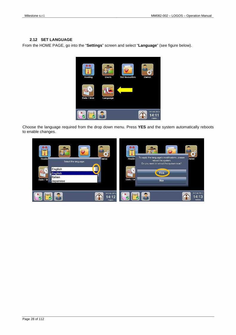
2.12 SET LANGUAGE From the HOME PAGE, go into the “Settings ” screen and select “Language ” (see figure below).
Choose the language required from the drop down menu. Press YES and the system automatically reboots to enable changes.

Milestone s.r.l. MM082-002 – LOGOS – Operation Manual
Page 29 of 112
2.13 LOAD LOGOS WITH WAX From the “Settings ” screen, select “Heating ” button or the WAX icon on the status bar (see figure below).
The HEATING screen will appear displaying information about the Heating Status and the Cavity Level (Main processing chamber on the left and WAX chamber on the right ).
Open the right cover of LOGOS and place paraffin in the RIGHT cavity (figure below).
It is necessary to fill the LOGOS WAX CAVITY (right side cavity) with approximately 4kg of histology grade WAX.

Milestone s.r.l. MM082-002 – LOGOS – Operation Manual
Page 30 of 112
In the “Heating settings ” screen the default value of HEATING WAX is: Off .
Log in as Administrator to switch on the Wax heating power, as shown in the figure below (yellow arrow). ON: Power on (wax heating starts when the unit is switched on) OFF: Power off
Only when the wax is ready for use (fully molten), the graph shows the lower level sensor as active (covered) and the maximum level sensor as inactive (uncovered), as shown in the figure above.
MAX and MIN levels for the MOLTEN WAX are etched on the LOGOS WAX CAVITY wall. Strictly maintaining the molten WAX level between t hese markings assures the
appropriate coverage of all three cassette layers o f the rack during process.
USER can only “S et as ready” the WAX (if allowed by the ADMINISTRAT OR in the USER Settings) when the WAX heating status icon becomes YELLOW and the “Set as ready”
button becomes active (see the figures below).
It is only possible to “Set as ready” the WAX when its temperature is 4°C lower than the preset temperature value, so a process can be immed iately started.
In any case, it is necessary that operator checks a ctual status of the WAX inside the CAVITY before setting “wax as ready”.
MAX
MIN

Milestone s.r.l. MM082-002 – LOGOS – Operation Manual
Page 31 of 112
OTHER FUNCTIONS:
o Temperature to maintain: wax is kept at this
temperature, when the unit is on.
o Molten Time: shows the time necessary to completely
melt the paraffin.
o Elapsed Time: shows the wax heating time remaining
before use.
The Molten Time is a pre-set value. Milestone s.r.l . strongly recommends NOT to modify it. The maintaining temperature is a default value set according to Milestone s.r.l. standard
programs. The modification of this value is only al lowed under direct control of Milestone applicative support.
LOGOS software will indicate with an alarm if the W AX level is incorrect. See paragraphs 2.13and 7.4.1 for how to manage the WAX, its reuse life and when proceeding with the
WAX cleaning protocol. ADMINISTRATOR/SERVICE can modify all parameters of these fields; incorrect use of
these settings may lead to system malfunction. Use only under direct control of Milestone s.r.l. technical support.
The WAX heating status icon indicates through a change in color the: • WAX levels. • WAX “Temperature to maintain”. The reagent status icon indicates status of WAX (and all the other reagents) used as a reagent and shows
through a change in color the reagent status based on n° of cassettes processed and/or cycles performed and/or expiration date. Please refer to chapter 4.

Milestone s.r.l. MM082-002 – LOGOS – Operation Manual
Page 32 of 112
2.14 HOW TO LOAD LOGOS WITH REAGENTS
LOGOS drawer hosts 9 tanks. It’s possible to use commercial tanks (already filled with reagents) or clean tanks (to be filled with reagents) which must be either supplied locally or purchased directly from the manufacturer. For details see Chapter 10: tanks 5 liters capacity (Ref. P/N 70170) and tanks 5 liters capacity xylene proof (Ref. P/N 70170F) are available.
Milestone medical application staff suggests the following use of the tanks:
2.14.1 Cleaning procedure for Cleaning Tanks
TO BE PERFORMED AFTER EVERY CHANGE OF CLEANING REAG ENTS • Reagents required: Xylene, Isoparaffin or substitute and Ethanol. • Purpose of cleaning: is performed on all CLEANING tanks that have potential contamination from WAX
residues. • When to clean: to be performed EVERY TIME cleaning reagents are changed. • Removal of tanks: open the drawer, press the rapid connectors and extract the tanks to be cleaned.
Dispose of reagent according to lab practices appropriate for that reagent.
It is possible to process up to 3 layers of the Spl it rack with 5 liters tanks and up to 2 layers with 1 US gallons (3.8 liters).
Do not insert tanks with a capacity lower than 3.8 liters because the reagent will be too much contaminated.
Do not use tanks higher than 30cm because the lengt h of the pipes will not be enough. See the chapter 2.14.2.
Reagent type Reagent name
Tank nr. 1 Fixative Formalin, FineFIX®
Tank nr. 2 Flushing Flushing
Tank nr. 3 Rinsing reagent #1 Ethanol\ Prowave®
Tank nr. 4 Rinsing reagent #2 Ethanol\ Prowave®
Tank nr. 5 Dehydration Ethanol \ Prowave®
Tank nr. 6 Clearing Isopropanol \ JFC® \ Prowave® \ Xylene
Tank nr. 7 Cleaning Xylene \ Isoparaffin
Tank nr. 8 Cleaning Ethanol
Tank nr. 9 Cleaning Water
It’s required to execute the cleaning procedure when the cleaning tanks are not commercial but either supplied locally or purchased directly from the manufacturer
because it’s possible to reuse them several times.
Milestone s.r.l. MM082-002 – LOGOS – Operation Manual
Page 33 of 112
• Cleaning procedure: perform a rinse in Xylene or Isoparaffin or substitute (close tank and shake for a few minutes), dispose of waste reagents and follow with two quick rinses in Ethanol.
• Reinstalling of tanks and reagent replacement: load tanks with fresh cleaning reagents, put the pipes, then insert the tanks and the rapid connectors in the corresponding position. Complete replacement of reagent that resets reagent management counts.
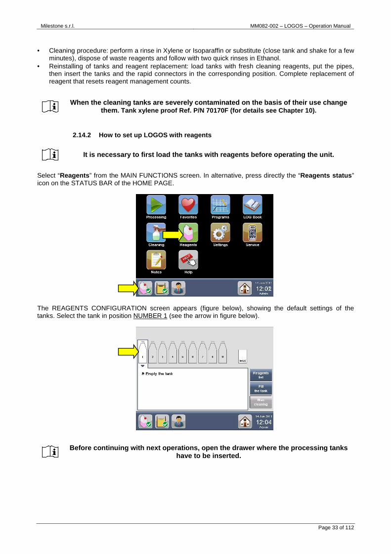
2.14.2 How to set up LOGOS with reagents
Select “Reagents ” from the MAIN FUNCTIONS screen. In alternative, press directly the “Reagents status ” icon on the STATUS BAR of the HOME PAGE.
The REAGENTS CONFIGURATION screen appears (figure below), showing the default settings of the tanks. Select the tank in position NUMBER 1 (see the arrow in figure below).
When the cleaning tanks are severely contaminated o n the basis of their use change them . Tank xylene proof Ref. P/N 70170F (for details se e Chapter 10).
It is necessary to first load the tanks with reagen ts before operating the unit.
Before continuing with next operations, open the dr awer where the processing tanks have to be inserted.

Milestone s.r.l. MM082-002 – LOGOS – Operation Manual
Page 34 of 112
• Start set up of the tanks from hose number 1, as shown below.
Each pipe is provided with a RAPID CONNECTOR to simplify insertion/extraction. Just press the rapid connector to easily insert/extract any pipes from each tank, as shown below.
• Press the rapid connector corresponding to the tube number 1, as shown below.
• Choose the plastic ring suitable for the reagent you want to use in each position (in case of position
Nr. 1, Formalin is required) as follows: press “Reagents list” from the Reagents configuration screen, look to the color and the short name of the reagent (Formalin), then choose the corresponding plastic ring.
There are numbered stickers 1-9 on each pipe and th eir position.
It’s required to insert the Formalin tank in position number 1. TANK POSITION IS COMPULSORY only for formalin.
Other tanks can be positioned according to user’s p reference request.
PRESS HERE

Milestone s.r.l. MM082-002 – LOGOS – Operation Manual
Page 35 of 112
The PLASTIC RING that corresponds to Formalin reagent (position 1) is white with the short name “FOR” . Now insert it in the metallic insert.
• Insert the CAP in the metallic insert. There are three types of silicon caps, suitable for tanks holes of 42-49mm, 32-38mm and 28-33mm diameter respectively.
• At the end, insert the METAL RING in the metallic insert. Screw it with the allen wrench (provided with
the unit) at approximately 10cm (4’’) from the bottom part of the metallic insert.
• The image below shows the final configuration.
• Insert the tank containing fresh reagent (Formalin in this case) in the correct position (hose number 1 in
this case), then insert the rapid connector in the corresponding position (number 1 in this case).
Always check that you have properly entered the rap id connectors.
Plastic ring
Cap
Metal ring

Milestone s.r.l. MM082-002 – LOGOS – Operation Manual
Page 36 of 112
• Only after positioning of the tank in the drawer, in the REAGENTS CONFIGURATION screen select the tank in position NUMBER 1 and press “Fill the tank”.
• The following message appears, click YES. The screen on the right appears showing the REAGENT
REPLACEMENT PROCEDURE; press Done to confirm and follow the steps:
• Select the reagent to insert in the drop-down menu (Formalin in this case). Press Done to confirm and return directly to the REAGENT CONFIGURATION screen (see next figure on the right).
Repeat the same procedure for all other tanks. Now you are ready to process.

Milestone s.r.l. MM082-002 – LOGOS – Operation Manual
Page 37 of 112
TANK NUMBER
REAGENT SHORT NAME
COLOR
1 Formalin FOR White 2 Flushing FLU Yellow
It’s required to insert the tanks with the order of the numbers showed in figure below . For example the tank referring to the tube number 3 and to the position number 3 (see the circle in figure below) must be inserted in the position 3 showed by the arrow below. The same concept is required for all the other tanks. It’s required to insert the tanks with the orientat ion showed in figure below: the tank number 1 has the cup on the right, not on the left (see the arro w). The same concept is required for all the other tanks.
The tanks as displayed by the software, with their numbers, short names and colors, correspond to the real tanks as positioned in the d rawer with their plastic rings.
1
2
3
4
5
6
7
8
9

Milestone s.r.l. MM082-002 – LOGOS – Operation Manual
Page 38 of 112
2.15 MOST USED PROGRAMS Insert FAVORITES programs in the HOME PAGE as follows:
1. Press “Settings ” from the MAIN FUNCTIONS screen and select “Set favorites ”.
2. Press “Not Defined ” button.
3. Select the CAVITY LEVEL, the PROTOCOL and the PROGRAM (figure below, yellow arrows).

Milestone s.r.l. MM082-002 – LOGOS – Operation Manual
Page 39 of 112
4. You can change TEXT and BACKGROUND COLOR by pressing “Choose the Button Color ”, (for example, see red circle in the figure below).
5. Press “Save Favorite ” to save changes (figure above, yellow arrow). 6. The program icon is now listed in the “Choose the Favourite to Set” screen.
7. Press “Home ” (figure above, red circle) to return to the HOME PAGE and view the Favourite protocol, if the user HOME PAGE is set as “FAVOURITES” (figure below).

Milestone s.r.l. MM082-002 – LOGOS – Operation Manual
Page 40 of 112
8. If the HOME PAGE is set as “MAIN FUNCTIONS”, press “Favorites ” to open the FAVORITES SCREEN (figure below).
2.16 OWNER SETTINGS Press “Settings ” from the MAIN FUNCTIONS screen and select “Owner ”. This function is available only for Service and Administrator.
The OWNER SETTINGS screen appears as shown in the picture below.
Select “General” to modify:
� Institute and Department name where unit is installed.
� Reagent Cassettes Alert Status. This number indicates that the reagent status is near expiration (on the base of the number of cassettes processed) and the reagents status icon turns from green to yellow (see chapter 4 for further details).

Milestone s.r.l. MM082-002 – LOGOS – Operation Manual
Page 41 of 112
� Reagent Cycles Alert Status. This number indicates that the reagent status is near expiration (on the base of the cycles run) and the reagents status icon turns from green to yellow (see chapter 4 for further details).
� Reagent Days Alert Status. This number indicates that the reagent status is near expiration (on the base of the days of use) and the reagents status icon turns from green to yellow (see chapter 4 for further details).
� Additional Cassettes Limit for each reagent (expressed in percentage): this value is checked by the software during the insertion of the cassettes to be processed, before starting a new program and allows to override the maximum cassettes limit (once only), according to the reagents parameters edited in the REAGENTS LIST (see chapter 4.1.1).
Select “Ventilation” to manage the upper (working area) and lower (drawer) exhaust fume fans, choosing between:
� Always ACTIVE. Both exhaust fans are activated at the switching on of the unit.
� Always OFF. Both exhaust fans are always off, even during the processing (not suggested).
NOT SUGGESTED. Risk of fumes in the laboratory environment.
� PROCESSING and COVER OPENING. The Upper ventilation is activated only during the processing
and when opening the covers. The Lower ventilation is always active.
Select “Remote connection” to edit and modify the network settings for remote assistance. Data required must be supplied by the Laboratory Network Administrator (Primary WINS not required). For example: IP Address 192.168.1.200
Subnet Mask 255.255.255.0
Default Gateway add. 192.168.1.1
DNS server address 192.168.1.6

Milestone s.r.l. MM082-002 – LOGOS – Operation Manual
Page 42 of 112
Select “Fixation limits” to set Minimum and Maximum Fixation Time. When enabled, before starting a protocol, the software warns user if the total fixation time is under or over the limits set and manages the Holding solution. Refer also to chapter 3.2.5 and 4.1.1.
“Run ID” is ticked, software requires user to enter the Run ID before running a program.
Select “Rinsings” and set if user needs to: � Load 1 or 2 rinsing tanks in the reagents configuration screen. � Modify rinsings processed cassettes limit.
ABLE OR DISABLE RUN ID CHECK ACCORDING TO YOUR INTE RNAL LABORATORY PRACTICE (GOOD LABORATORY PRACTICE, GLP).
These parameters are factory set to assure optimal results. Don’t modify them.
For any possible clarification or any request for a ssistance please contact either our application support: [email protected] .

Milestone s.r.l. MM082-002 – LOGOS – Operation Manual
Page 43 of 112
3 OPERATE WITH LOGOS LOGOS is controlled by the Touch Control Terminal, which is a Windows CE 6.0 based.
It is an HYBRID SYSTEM that can heat the specimens processing solutions by Microwaves or by conventional or with combined Conventional/Microwave heating.
The Microwave/Resistance power output is automatically controlled by a PID (Proportional Integrative Derivative) system, which allows the operator to set up the desired real parameters (Time and Temperature) by simply drawing a curve. If a pre-stored program is used, it is only required to adjust the time of the proc edure in relation to the application specifications.
Thanks to the TIME at TEMPERATURE working procedures, LOGOS allows consistency and reproducibility of high quality results. The unit will always reproduce the same conditions of temperature in the set times by automatically adjusting the Microwave/Resistance power level.
LOGOS has two cavities: a MAIN cavity and a WAX cavity. This feature allows user to run a process in two different ways:
- AUTOMATIC mode : wax will be automatically pumped from the WAX cavity to the MAIN cavity for the impregnation phase.
- DUAL mode: USER is required to MANUALLY move the RACK from the MAIN to the WAX CAVITY. A new process can immediately be started in the MAIN CAVITY without waiting for the end of the impregnation step. This allows for significant TIME SAVING.
The following section shows how to create, store, modify and run a program with the Touch Control Terminal.
3.1 LOADING CASSETTES INTO THE SPLIT RACK The Split Rack is made by 3 separate layers; each layer holds 70 cassettes for a total of 210 cassettes (figure below). Load the 3 layers of the SPLIT RACK Ref. P/N 66165 with cassettes. Each LAYER comes in a split design of two halves for simultaneous, convenient use in different grossing rooms and embedding stations. Each layer is provided with a locking mechanism (figure below, red arrow) to assure perfect closing of the two halves.
Fully load each layer with cassettes, starting from the bottom layer first to avoid a random placement of cassettes over the three layers.
Start loading cassettes into a new layer only when the layer in use is full, thus avoiding a possible “low reagent” situation in the cavity.

Milestone s.r.l. MM082-002 – LOGOS – Operation Manual
Page 44 of 112
Position the CASSETTE FIXING DISK on top of the last layer in use and insert it in the Main chamber cavity (figure below).
3.2 RUN A PROGRAM
3.2.1 Run of the most used program Select a Favorite program (figure below, yellow arrow) out of the list of FAVORITE PROTOCOLS (see chapter 2.15).
Wax and Reagent status bar: see chapters 4 and 4.3 how to set these warnings.
The fixing disk must always be used, with either 1, 2 or full layer rack in order to avoid possible spilling out of cassettes from the rack du ring the processing.
Milestone s.r.l. MM082-002 – LOGOS – Operation Manual
Page 45 of 112
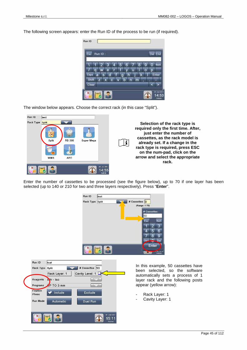
The following screen appears: enter the Run ID of the process to be run (if required).
The window below appears. Choose the correct rack (in this case “Split”).
Enter the number of cassettes to be processed (see the figure below), up to 70 if one layer has been selected (up to 140 or 210 for two and three layers respectively). Press “Enter ”.
Selection of the rack type is required only the first time. After,
just enter the number of cassettes, as the rack model is already set. If a change in the
rack type is required, press ESC on the num-pad, click on the
arrow and select the appropriate rack.
In this example, 50 cassettes have been selected, so the software automatically sets a process of 1 layer rack and the following posts appear (yellow arrow): - Rack Layer: 1 - Cavity Layer: 1

Milestone s.r.l. MM082-002 – LOGOS – Operation Manual
Page 46 of 112
The “Reagents” (in this case: “Eth-Iso”) and the “Program” (in this case “Up to 3mm”) are automatically displayed (see figure above, red circle), according to the Favorite protocol selected (figure below).
There are now two different possibilities of “Run Mode ”: Automatic or “Dual Run”.
1) Run Mode: “Automatic ”
Select “Automatic ” as Run Mode (yellow arrow below): at the end of the last phase in the Main chamber, the Wax will be AUTOMATICALLY pumped from the Wax cavity to the Main Processing cavity. Press “Go” (red circle).
The heating fixation phase is included as default; if not required, select “Exclude” to skip it. It’s suggested to include the heating fixation phase in the process to standardize the
results.
Milestone s.r.l. MM082-002 – LOGOS – Operation Manual
Page 47 of 112
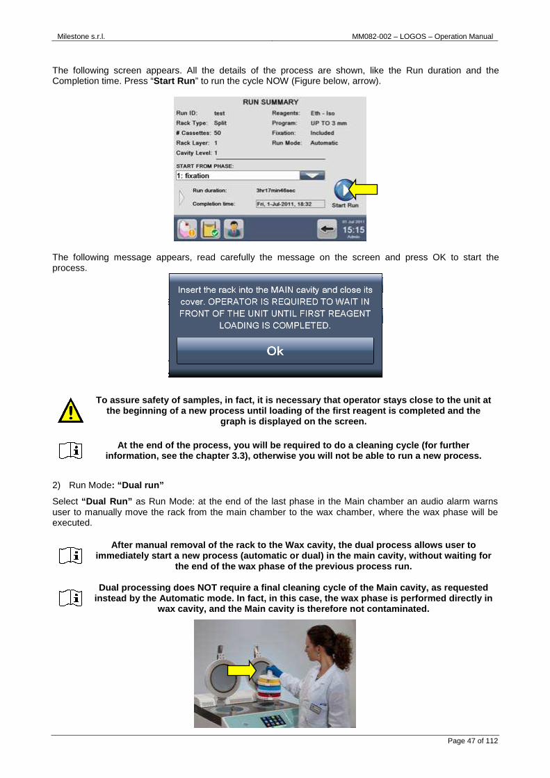
The following screen appears. All the details of the process are shown, like the Run duration and the Completion time. Press “Start Run ” to run the cycle NOW (Figure below, arrow).
The following message appears, read carefully the message on the screen and press OK to start the process.
2) Run Mode: “Dual run”
Select “Dual Run” as Run Mode: at the end of the last phase in the Main chamber an audio alarm warns user to manually move the rack from the main chamber to the wax chamber, where the wax phase will be executed.
To assure safety of samples, in fact, it is necessa ry that operator stays close to the unit at the beginning of a new process until loading of the first reagent is completed and the
graph is displayed on the screen.
At the end of the process, you will be required to do a cleaning cycle (for further information, see the chapter 3.3), otherwise you wi ll not be able to run a new process.
After manual removal of the rack to the Wax cavity, the dual process allows user to immediately start a new process (automatic or dual) in the main cavity, without waiting for
the end of the wax phase of the previous process ru n.
Dual processing does NOT require a final cleaning c ycle of the Main cavity, as requested instead by the Automatic mode. In fact, in this cas e, the wax phase is performed directly in
wax cavity, and the Main cavity is therefore not co ntaminated.

Milestone s.r.l. MM082-002 – LOGOS – Operation Manual
Page 48 of 112
Select “Dual Run ” as Run mode (yellow arrow) and then press “Go” (red circle).
The following screen appears. All process details are shown, like Run duration, Completion time and also “Time to move the rack ”, that shows exactly when the presence of user is required to manually move the rack to wax cavity (see the arrow below). Press “Start Run ” to begin the cycle NOW (Figure below, red circle).
The following message appears, read carefully the message on the screen and press OK to start the process.
In fact, to assure safety of samples, it is necessa ry that operator stays close to the unit at the beginning of any new process, until loading of the first reagent is completed and the
graph is displayed on the screen.
Should the operator not be prese nt at “Time to move the rack”, after 5 minutes the d ual process turns to automatic and wax is automatically pumped into the Main cavity to keep
samples safe. For further details see the chapter 3 .2.3.

Milestone s.r.l. MM082-002 – LOGOS – Operation Manual
Page 49 of 112
Detailed processing information appears on the screen, while the program is running. For further information, press on the arrow (see red circle):
� Picture on the left: name of the current phase and PHASE GRAPH with pre-set/real temperature or pressure. Under the graphic: PROTOCOL TYPE, number of cassettes, thickness, Run mode and processing COMPLETION TIME.
� Picture on the right: reagent temperature, stirrer speed and ELAPSED TIME of the current phase (highlighted in blue).
The end of a protocol is different depending on whether the process has been run in “automatic ” or “dual ” mode.
1. An “Automatic ” process ends with wax impregnation performed in the main chamber (left cavity), as shown below. An audio alarm warns that program is over; press “Unload reagent ”, then “Extract the rack ” and “Exit ”.
Press “Abort” processing to abort the program and u nload the cassettes.
Before running a new process, it’s required to run a cleaning cycle, as described in the chapter 3.3.

Milestone s.r.l. MM082-002 – LOGOS – Operation Manual
Page 50 of 112
A “Dual ” process ends with wax impregnation performed in the wax cavity (right cavity), as shown below. An audio alarm warns that program is over; press “Extract the rack ” and “Exit ”.
3.2.2 Run a standard program Press “Processing ” from the MAIN FUNCTIONS screen (figure below).
The following screen appears: enter the Run ID of the process to be run, if required (in this case “test”).
The window shown below appears. Choose the rack (in this case: Split), then enter number of cassettes (200 in this case) to be processed (see the figure below, yellow arrows), up to 70 if one layer has been selected (up to 140 or 210 for two and three layers respectively). Press “Enter ” (red circle).
You can immediately start a new process without run ning a cleaning cycle, because the Main chamber has not been contaminated with wax.

Milestone s.r.l. MM082-002 – LOGOS – Operation Manual
Page 51 of 112
In the example, 200 cassettes have been selected, so the software automatically sets a process of 3 layers rack and the following posts appear (figure below, arrow): - Rack Layer: 3 - Cavity Layer:3
Choose the processing reagents (for example “Eth-Iso”) and the protocol (in this case “Overnight 5mm fatty”), as shown below.
Selection of the rack type is required only the fir st time. After, just enter the number of cassettes, as the rack model is already set. If a c hange in the rack type is required, press
ESC on the num-pad, click on the arrow and select t he appropriate rack.

Milestone s.r.l. MM082-002 – LOGOS – Operation Manual
Page 52 of 112
The following screen appears.
To run the process follow the instructions reported above, in the chapter 3.2.1.
3.2.3 Run two processes simultaneously
When running parallel processing, it is required to perform the pre-soaking outside the unit.
In “Dual Run” Mode (described in the chapter 3.2.1 point 2), an audio alarm warns the operator that the last phase in the Main chamber has been completed and rack must be manually moved from the main chamber to the wax chamber, to execute the wax phase. Before moving the rack, the following screen appears, with an audio alarm that requires user to press OK (red circle, left figure below) to unload the reagent from the Main cavity (right figure below) and to automatically execute the vaporization step (if required by the program in use); during this operation, it is required that operator stays near the unit and wait until this procedure is completed (approx 5 minutes).
On completion of the reagent unloading procedure (and of vaporization, if required by the program in use), a new alarm starts advising the operator that it is time to manually move the rack from the main chamber to the wax chamber.
Should the operator not be able to stop the alarm a nd press OK to start unloading of the reagent, after 4 minutes the system automatically s tarts the unloading procedure.
Removal of the rack must be done in 3 minutes to av oid damaging the samples. Should this not be done, the system automatically p umps wax in the main cavity to
preserve samples.

Milestone s.r.l. MM082-002 – LOGOS – Operation Manual
Page 53 of 112
When rack has been moved from main to wax chamber, press OK (red circle above) to start WAX impregnation in wax cavity . The following screen appears (left figure below) with a new audio alarm.
While the wax phase is running in the wax retort, it’s possible to start a new process in the main cavity, as shown below.
Below is an example of impregnation phase running in the wax cavity.
Press OK within 1 minute to start Wax impregnation. Should this not be done, the system automatically s tarts wax impregnation in wax cavity.
Logos software does not allow starting of a new pro gram in the Main cavity if the wax program, simultaneously running in the wax cavity, is not completed by the time the wax
phase of the new program to be run in the Main cavi ty will need to start.

Milestone s.r.l. MM082-002 – LOGOS – Operation Manual
Page 54 of 112
During the wax impregnation phase, it’s possible to run a new process in the Main cavity. Press (see arrow in figure above):
• “Processing ” to run a standard or a modified protocol, as described in the chapter 3.2.2. • “Favourites ” to run a Favourite protocol, as described in the chapter 3.2.1. • “Main Cavity Cleaning ” to run a cleaning of the Main Cavity, as described in the chapter 3.3. Please notice also that, when a process is running in the Main chamber, it is also possible to run just a wax phase in the Wax chamber. Also in this case, it is necessary that the wax phase of the program running in the Main Chamber does not require starting before the wax phase started in the Wax cavity has been completed.
3.2.4 Run a program using the STEP START function In the starting screen listing all process details (“Run Summary ”), select the starting phase you require, as shown below.
In the example, “Ethanol ” is selected as the starting phase (so, phase number 4), and then press “Start Run ”.
3.2.5 Run a DELAYED PROGRAM Press “Processing” from the MAIN FUNCTIONS screen. The window below appears, if either a Favorite program (see chapter 3.2.1) or a Standard program (see chapter 3.2.2) is selected. Enter the exact number of cassettes in the box, choose if fixation phase must be excluded or not, select the Run Mode and press “Go delay” (figure below, arrow).

Milestone s.r.l. MM082-002 – LOGOS – Operation Manual
Page 55 of 112
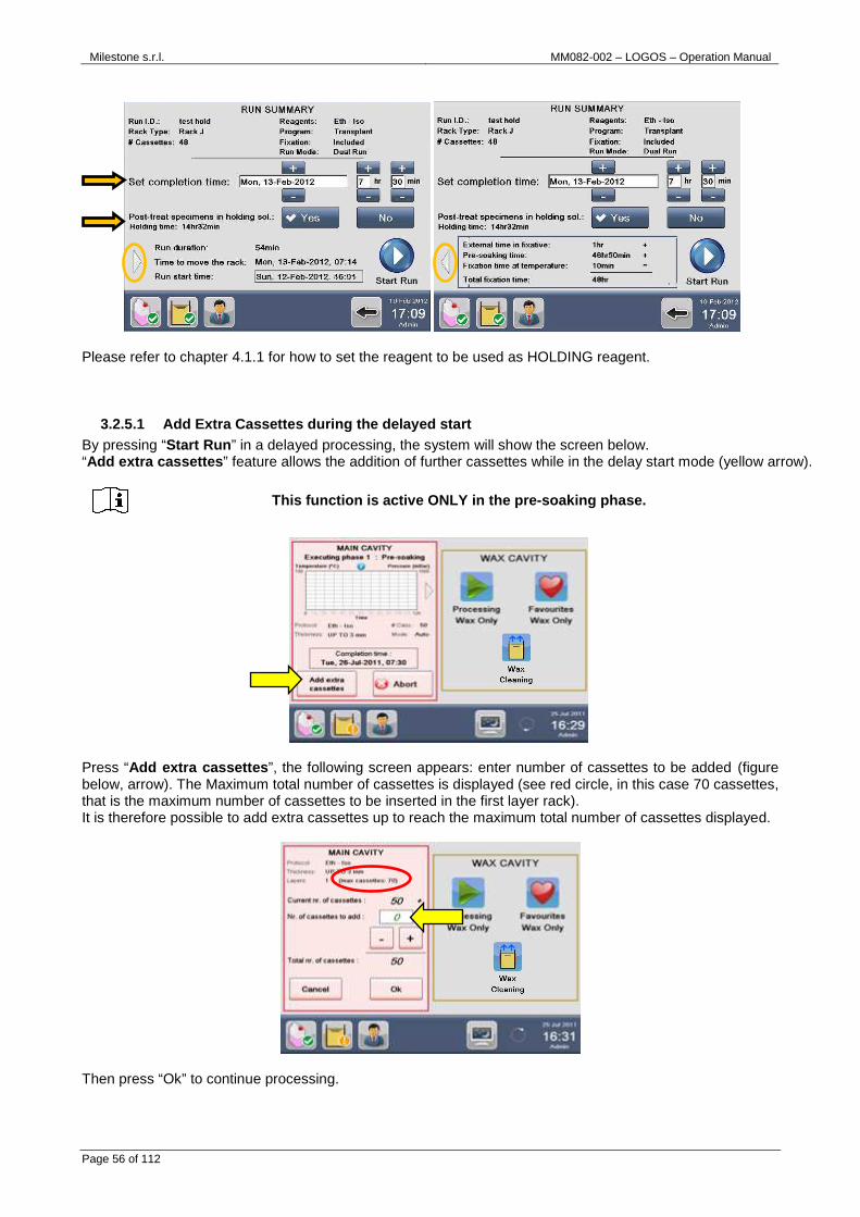
The following window appears: set the completion time (see arrow). In fact, “Delay Start” function allows setting when the program has to finish, without modification of the existing protocol. The system keeps samples immersed in formalin at ambient temperature (PRESOAKING TIME) and automatically calculates the starting time to complete the processing as set by user.
By selecting “Enable Limits” and entering Min and Max fixation times (see chapter 2.16) and figure below right, when starting a program the system calculates the time necessary to keep samples in HOLDING SOLUTION (default reagent Flushing MIX). In fact, on the base of the: -external time in fixative (value entered by user, requested only if fixation limits are enabled) -fixation time at temperature (value set in the program) the software calculates by difference the necessary pre-soaking time to reach the Max fixation limit set. Moreover software keeps samples in HOLDING SOLUTION up to the start of the program.
Milestone s.r.l. MM082-002 – LOGOS – Operation Manual
Page 56 of 112
Please refer to chapter 4.1.1 for how to set the reagent to be used as HOLDING reagent.
3.2.5.1 Add Extra Cassettes during the delayed star t By pressing “Start Run ” in a delayed processing, the system will show the screen below. “Add extra cassettes ” feature allows the addition of further cassettes while in the delay start mode (yellow arrow).
Press “Add extra cassettes ”, the following screen appears: enter number of cassettes to be added (figure below, arrow). The Maximum total number of cassettes is displayed (see red circle, in this case 70 cassettes, that is the maximum number of cassettes to be inserted in the first layer rack). It is therefore possible to add extra cassettes up to reach the maximum total number of cassettes displayed.
Then press “Ok” to continue processing.
This function is active ONLY in the pre-soaking pha se.

Milestone s.r.l. MM082-002 – LOGOS – Operation Manual
Page 57 of 112
3.3 RUN A CLEANING CYCLE OF THE MAIN CAVITY At the end of an “Automatic ” process (see the chapter 3.2.1, point 1), it is required to carry out a cleaning cycle of the main cavity, as this has been filled with wax. Unload the reagent and extract the rack by pressing the corresponding icons in the figure below; download the cassettes and select the appropriate cleaning protocol required (yellow arrow) in the processing screen, press “Start Cleaning” (red circle below) and run directly a cleaning program.
There are five default cleaning protocols, two requiring the use of two cleaning tanks “Isopar-Eth” or “Xyl-Eth”; other three requiring the use of three cleaning tanks “Isopar-Eth-Water” or “Xyl-Eth-Water” and “Xyl-Eth-Water-FAST”, as shown below.
If you select: Check that:
• “Isopar-Eth”: “Cleaning Isoparaffin” and “Cleaning Ethanol” are included in the reagents configuration, otherwise add them.
• “Isopar-Eth-Water”: “Cleaning Isoparaffin”, “Cleaning Ethanol” and “Cleaning Water” are included in the reagents configuration, otherwise add them.
• “Xyl-Eth”: “Cleaning Xylene” and “Cleaning Ethanol” are included in the reagents configuration, otherwise add them.
• “Xyl-Eth-Water”: “Cleaning Xylene”, “Cleaning Ethanol” and “Cleaning Water” are included in the reagents configuration, otherwise add them.
• “Xyl-Eth-Water-FAST”: “Cleaning Xylene”, “Cleaning Ethanol” and “Cleaning Water” are included in the reagents configuration, otherwise add them. This is a Fast cleaning reagent cycle as it takes just 1 hour, compared to 1.20-1.30hr of the others.
Rack CANNOT be positioned inside the cavity when ru nning this “FAST” cleaning cycle, but it must be cleaned outside the cavity.
The cleaning procedure based on the 2 tanks cleaning reagents (“Isopar-Eth” or “Xyl-Eth”) is suggested when all other 7 tanks positioned in the Logos drawer are already in use for processing, and this makes impossible the use of 3 tanks for cleaning.
The above reagents must be onsite and available at installation time of unit.
It is also possible to clean also the rack (WITHOUT cassettes) inside the Main cavity, for further information see the chapter 7.2.1.

Milestone s.r.l. MM082-002 – LOGOS – Operation Manual
Page 58 of 112
To start the cleaning cycle later, press “Exit” and go to the Main menu, as shown below (red circle).
When ready to start the cleaning cycle, press “Cleaning ” from the Main Menu, then “Main cavity cleaning ”.
Select the appropriate cleaning protocol from the list below and press “Ok” (right figure).
If you perform a cleaning cycle with 3 tanks, “Isop ar-Eth-Water” or “Xyl -Eth-Water”, it’s required to use a clean tank (to be filled with tap water), which must be either supplied locally or purchased directly from the manufacturer (for details see Chapter 10).
If you perform a cleaning cycle with only 2 tanks, “Isopar/Eth” or “Xyl/Eth”, without the step of water, at the end of the cleaning protocol it is required to:
- dry the Main cavity using paper towel, - wash the rack under tap water and dry it using pape r towel.
If you perform a cleaning cycle with only 2 tanks, without the step of water, make sure to leave the Main cavity cover open for at least 30 mi nutes before starting a new processing run.
Milestone s.r.l. MM082-002 – LOGOS – Operation Manual
Page 59 of 112
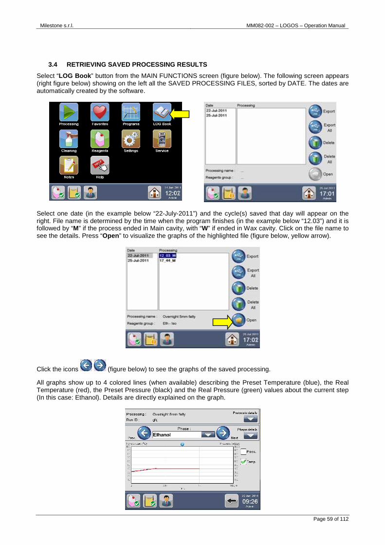
3.4 RETRIEVING SAVED PROCESSING RESULTS
Select “LOG Book ” button from the MAIN FUNCTIONS screen (figure below). The following screen appears (right figure below) showing on the left all the SAVED PROCESSING FILES, sorted by DATE. The dates are automatically created by the software.
Select one date (in the example below “22-July-2011”) and the cycle(s) saved that day will appear on the right. File name is determined by the time when the program finishes (in the example below “12.03”) and it is followed by “M” if the process ended in Main cavity, with “W” if ended in Wax cavity. Click on the file name to see the details. Press “Open ” to visualize the graphs of the highlighted file (figure below, yellow arrow).
Click the icons (figure below) to see the graphs of the saved processing. All graphs show up to 4 colored lines (when available) describing the Preset Temperature (blue), the Real Temperature (red), the Preset Pressure (black) and the Real Pressure (green) values about the current step (In this case: Ethanol). Details are directly explained on the graph.

Milestone s.r.l. MM082-002 – LOGOS – Operation Manual
Page 60 of 112
Press “Protocols details ” to see them, if required (see below).
Press “Phase details ” to see them, if required (see below).
Press the icon to go back to the Saved processing screen.
3.4.1 How to delete a saved processing
Select a Process and press “Delete ” to delete ONLY the process highlighted (left figure). Select a Date and press “Delete ” to delete all the processes saved that day (right figure).
Alternatively press “Delete All ” if you want to delete ALL the programs stored on LOGOS. Press “Home ” to return to the main menu.
Milestone s.r.l. MM082-002 – LOGOS – Operation Manual
Page 61 of 112
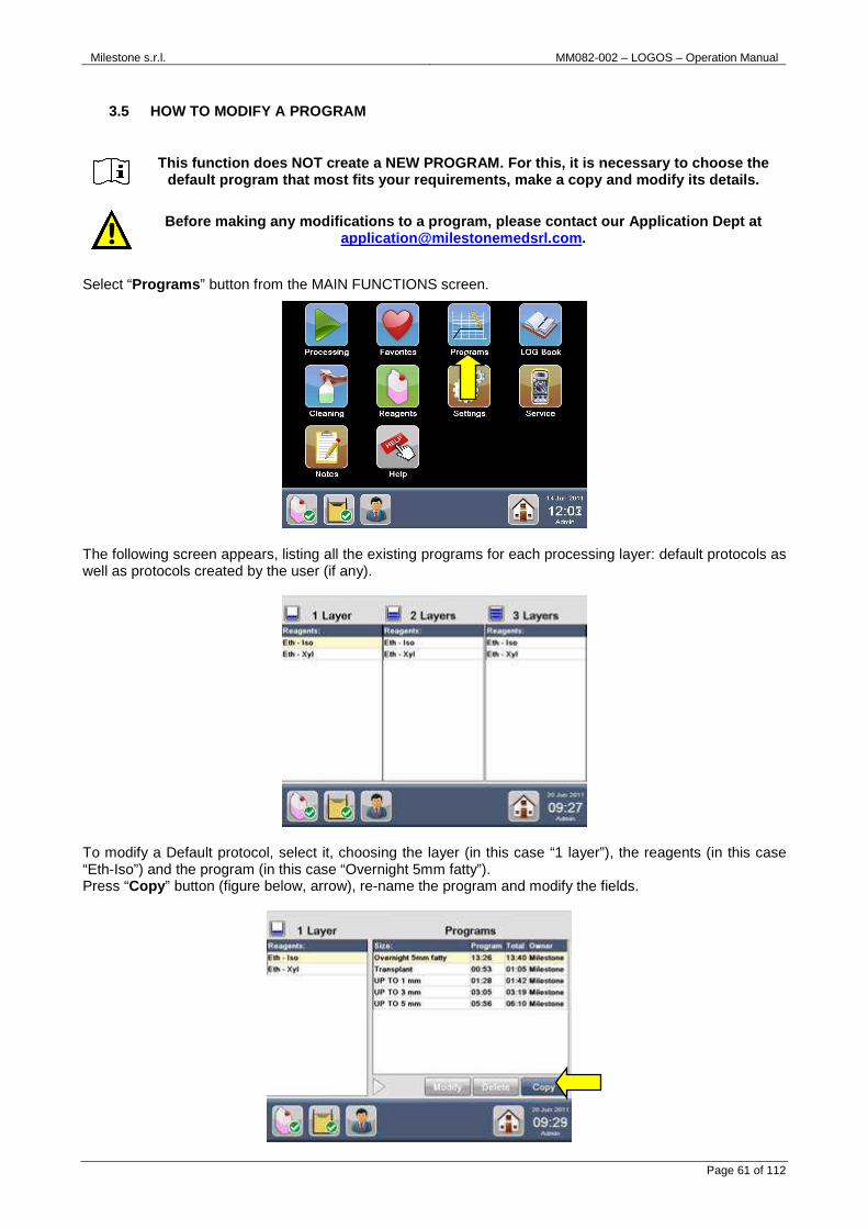
3.5 HOW TO MODIFY A PROGRAM
Select “Programs ” button from the MAIN FUNCTIONS screen.
The following screen appears, listing all the existing programs for each processing layer: default protocols as well as protocols created by the user (if any).
To modify a Default protocol, select it, choosing the layer (in this case “1 layer”), the reagents (in this case “Eth-Iso”) and the program (in this case “Overnight 5mm fatty”). Press “Copy ” button (figure below, arrow), re-name the program and modify the fields.
This function does NOT create a NEW PROGRAM. For th is, it is necessary to choose the default program that most fits your requirements, m ake a copy and modify its details.
Before making any modifications to a program, pleas e contact our Application Dept at [email protected] .

Milestone s.r.l. MM082-002 – LOGOS – Operation Manual
Page 62 of 112
Modification of a user’s protocol does NOT require copying it before making the changes required.
3.5.1 How to modify a cleaning program
Select “Cleaning” from the MAIN FUNCTIONS screen, then press “Modify Cleaning Program ”.
The following screen appears, showing all existing programs for the Main cavity (on the left) and for the Wax cavity (on the right): default protocols as well as protocols created by the user (if any).
Choose the program of your interest. Press “Copy ” button (figure above, arrow), re-name the program and modify the fields.
The “Modify “and “Delete” buttons are made availabl e only for already copied protocols.
For safety reasons, the factory pre-stored protocol s cannot be directly modified or deleted.
Take care to modify ONLY the Time At Temperature pa rt of the curve. Do not modify the Ramp - up time.
This function does NOT create a NEW PROGRAM. For th is, it is necessary to choose the default program that most fits your requirements, m ake a copy and modify its details.
Before making any modifications to a program, pleas e contact our Application Dept at [email protected] .

Milestone s.r.l. MM082-002 – LOGOS – Operation Manual
Page 63 of 112
4 REAGENTS MANAGEMENT Select “Reagents ” from the MAIN FUNCTIONS screen or press directly the “Reagents status icon ” on the STATUS BAR of the HOME PAGE.
The REAGENTS MANAGEMENT window appears, showing the settings and the status of all the reagents loaded in the unit (Wax included). It is possible to check the reagents STATUS by selecting the relative TANK (or WAX CAVITY) in the upper part of the screen.
For a proper operation of the unit, when a modifica tion of a cleaning protocol of the Main cavity is done, only resistance heating is possible in the first two phases of the cleaning
procedure (and not microwave heating).
The “Modify“ and “Delete” buttons are made availabl e only for already copied protocols.
For safety reasons, the factory pre-stored protocol s cannot be directly modified or deleted.
Take care to modify ONLY the Time At Temperature pa rt of the curve. Do not modify the Ramp - up time.

Milestone s.r.l. MM082-002 – LOGOS – Operation Manual
Page 64 of 112
4.1 REAGENT REUSE LIFE The PARAMETERS of the reagent selected are shown in details (figure below) on the lower part of the screen.
The REUSE LIFE of the reagent can be checked by:
(1) Expiration Date . This date shows the reagent EXPIRING DATE, according to requirements set into the Reagent List (red box, figure above). For further details see the chapter 4.1.1.
(2) Performed cycles. This field automatically shows the cycles already completed (red square, figure above).
(3) Processed cassettes. This field automatically shows the cassettes already processed (red square, figure above).
Additional information is shown on the right side of the windows (green box square) and refers to the REAGENT SETTINGS edited into the “Reagent list ” (figure above, arrow).See chapter 4.1.1 for further clarifications.
4.1.1 Reagent settings
From the REAGENT CONFIGURATION window, select the “Reagent List ” icon: the LIST of preset reagent appears.
Default reagents settings of LOGOS (expiration date , max number of cassettes and max number of cycles) refer to use of tanks of 5 liters /US gallons capacity and to processing
without papers and sponges. In any other case, like use of different tanks capacity or use of sponges, please contact our Application Dept at [email protected] to
get proper instructions.

Milestone s.r.l. MM082-002 – LOGOS – Operation Manual
Page 65 of 112
REUSE LIFE of each reagent can be defined using the check boxes (see figure above on the right, red circle):
(1) Check the expiration date. Tick this box to check the reagent expiration date, according to your requirements (not compulsory).
(2) Check the performed cycles. Tick this box to check the maximum number of cycles to be carried out with the reagent in use.
(3) Check the processed cassettes. Tick this box to check the maximum number of cassettes to be processed with this reagent.
(4) Use for RINSING phases. Tick this box to set the DEHYDRATION reagent to be used also as RINSING reagent.
(5) Use for HOLDING phases. Tick this box to set the reagent to be used as HOLDING reagent (refer to chapter 3.2.5).
(6) Use for FLUSHING phases. Tick this box to set the reagent to be used as FLUSHING reagent.
Click on the relative Check boxes to activate the settings described above (points 1,2,3 in the chapter 4.1) regarding date of next change, number of maximum processing runs and/or processed cassettes performed with any reagent, so that the system automatically warns before the process starts.
“Add ” a new reagent or “Delete ” it (figure below, red circle) by pressing on the relative icon. Default reagents cannot be deleted. Every new added reagent can be used for any phase.
The REAGENTS SETTINGS makes the REAGENTS STATUS icon turn from GREEN to YELLOW to RED (figure above, arrow), depending on the remaining reuse life of the reagents (for example 1 day, 1 cycle and/or 1 full cassette rack, as described in the chapter 2.16). For example, if you set 630 as max cassettes limit, the Reagents status icon is green until 410 cassettes (one full rack before reaching the limit); then turns to yellow from 411 to 630 and then to red at 631. When RED, processing cannot be launched.
Press the icon to return to the Reagent Management screen and save any modification.
The software allows skipping this wa rning (after entering the number of cassettes to process) by entering a value in percentage of max l imit that can be edited into the OWNER
SETTINGS (see chapter 2.16 under “Additional casset tes limit for each reagent”).

Milestone s.r.l. MM082-002 – LOGOS – Operation Manual
Page 66 of 112
4.1.2 Recommendation for reuse life The following recommendations are conceived as a guideline to ensure quality processing.
REAGENT CHECKED FOR:
REAGENT MAX
DAYS MAX
CYCLES MAX CASSETTES
5lt tanks MAX CASSETTES 3.8lt tanks (gallon)
USE FOR
Flushing MIX 30 10 840 672 Holding/Flushing WAX 30 10 840 840
FineFIX 30 10 1000 800 Formalin 30 10 1000 800 Ethanol 30 7 420 336 Rinsing Prowave 30 7 420 336
Prowave2 30 7 550 440 Isopropanol 30 7 420 336
Isoparopanol2 30 7 550 440 JFC 30 7 550 440
Xylene 30 10 630 504 Dewave 30 7 420 336
Clearwave 30 7 420 336 Clearwave2 30 7 550 440
Cleaning Ethanol 7 5 \ \ Cleaning Isoparaffin 7 5 \ \
Cleaning Water 7 5 \ \ Cleaning Xylene 7 5 \ \ Cleaning Dewave 7 5 \ \
Cleaning Clearwave 7 5 \ \ Cleaning Prowave 7 5 \ \
Default reagents settings are facto ry set, to assure optimal results. Don’t modify the m. For any possible clarification or any request for a ssistance please contact either our application support: [email protected] to get proper instructions.

Milestone s.r.l. MM082-002 – LOGOS – Operation Manual
Page 67 of 112
4.2 REAGENT REPLACEMENT PROCEDURE
CASE A: When a reagent NOT used for rinsing has expired its reuse life (in this case: number of processed cassettes), a RED symbol appears over the corresponding tank and the word “Replace” blinks in red. The reagents STATUS ICON also turns from green to RED (figure below, arrow). 1) Select the reagent EXPIRED (in this case Flushing MIX) and press the “Replace Reagent ” button (red
circle, figure below).
2) The screen below appears, showing the reagent replacement procedure. Follow the procedure displayed
on the screen.
3) Open the drawer where the processing tanks are positioned (figure below), remove the tank from the position indicated by the software (number 2 in this case) and press “Done” to confirm (figure above, red circle).
Handle with care and store in a cold dry space using a tightly closed container. Vapors may collect in empty containers. Treat empty containers as hazardous.
Waste material should be disposed of in an approved incinerator or in a designated landfill site, in compliance with all federal, provincial an d local government regulation.
Some reagents can have potential health effects and cause environmental pollution if not correctly disposed.
For further information please refer to the MSDS (M aterial Data Safety Sheet) provided by your supplier.
Before starting the procedure, a message reminds th at this operation will reset reagent management count to zero. Press “Yes” to confirm.

Milestone s.r.l. MM082-002 – LOGOS – Operation Manual
Page 68 of 112
4) Insert a new tank containing fresh reagent (Flushing MIX in this case) in the position indicated by the
software (number 2 in this case). The software, as a default, suggests filling with the same reagent already loaded into the tank. To load a different reagent, select it from the drop-down menu (figure below, arrow), press “Done” to confirm (red circle) and return directly to the Reagent configuration screen.
5) The software will automatically save all the settings. 6) After the replacement, the software resets the reagent management count to zero and the loading date
automatically changes to the current date (figure below, red circle). The reagents status icon also turns from red to GREEN (figure below, arrow).
After positioning of a new tank in the drawer, make sure that its rapid connector is properly connected, as described in the chapter 2.1 4.2.

Milestone s.r.l. MM082-002 – LOGOS – Operation Manual
Page 69 of 112
CASE B: When a reagent USED ALSO for rinsing (in this case Ethanol – tank 5) has expired its reuse life (in this case the number of processed cassettes) a RED symbol appears over the ETHANOL reagent (tank 5) BUT the word “Replace” blinks in red over the RINSING 1 reagent (tank 3). 1) Select the RINSING 1 reagent and press the “Replace Reagent ” button.
2) Follow the procedure how to replace the reagent described above, at points 2,3,4,5 and 6 for CASE A.
3) After the replacement, the software resets the reagent management count to zero and renames the old RINSING1 reagent as new DEHYDRATION reagent (figure below). The software renames the other tanks containing the reagent used also for rinsing as Rinsing 1 reagent and Rinsing 2 reagent, according to the number of cassettes already processed (the example below shows the old dehydration reagent renamed as Rinsing 2).
This procedure has been conceived to increase shelf life of Ethanol allowing more use as Rinsing despite the expiration as dehydration reagent.

Milestone s.r.l. MM082-002 – LOGOS – Operation Manual
Page 70 of 112
4.3 WAX REPLACEMENT
When wax needs to be changed because heavily contaminated, dirty or smells of alcohols that a “wax cleaning cycle” (see the chapter 7.4.1) cannot eliminate, the replacement operation is possible as follows:
1) If wax reuse life has expired, a RED icon appears over the Wax Cavity (REAGENT CONFIGURATION screen, red circle) and the word “Replace ” is RED. Select the WAX CAVITY and press “Replace reagent ” button (figure below, arrow).
2) The screen below appears, showing the WAX replacement procedure. Follow the procedure displayed
on the screen.
HOW TO OPERATE: • Lift up the frontal panel.
A message reminds that this operation will reset wa x management count to zero. Press “Yes” to confirm.

Milestone s.r.l. MM082-002 – LOGOS – Operation Manual
Page 71 of 112
• Lock the tube on the unit as shown in figure below and place the other end of the hose into a wax waste container, then turn the lever down to open.
• After the replacement, the software resets Wax management count to zero and the loading date
automatically changes to the current date.
3) Wait until the new solid wax you have loaded has melted (100 minutes). If molten wax is loaded, the
Wax status icon becomes yellow. Check the wax status (fully molten) and press “Set as ready ” button, as indicated in chapter 2.13.
With Logos, it is possible to load solid as well as already molten new paraffin.

Milestone s.r.l. MM082-002 – LOGOS – Operation Manual
Page 72 of 112
5 POWER FAILURE MANAGEMENT
5.1 EXTERNAL POWER SUPPLY The LOGOS can be equipped with an external UPS system, as described in the chapter 2.5.5., so that, in case of power failure, the software can put the specimens rack in “Safe mode”. In case of power failure during any processing phase, the program turns to Pause mode and the following screen appears:
The MAIN POWER FAILURE ALARM is audible for 3 minutes with an intermittent audio signal. The insulation of the cavities assures that the reagent loaded and the wax are kept warm during this period. During the 3 minutes COUNTDOWN… An auxiliary connector exit on the back of the unit is activated: here it is possible to connect an external light/sound alarm or a beeper to call the hospital service assistance to remove the specimens rack from the LOGOS (see the chapter 2.6).
Should the main power supply turn on during the 3 m inutes of Main Power Failure alarm mode, the program will automatically re-start from the point it was interrupted.

Milestone s.r.l. MM082-002 – LOGOS – Operation Manual
Page 73 of 112
5.2 WHAT HAPPENS DURING POWER FAILURE? In case of power failure, these functions are interrupted:
- Microwaves emission
- Wax heating
- Tissue processing
The terminal and the built-in stirrers remain operative in order to put the samples in the “safety position”.
The Terminal Computer remains active during the countdown, but:
- If during this time the main power comes back on, the system will restart from the point the program stopped;
- Instead, if the system goes in “Power failure procedure” at the end of the countdown (3 minutes), at the next start up the system will advise you of what happened, showing the details of the step where the program stopped, thus allowing, through a STEP START program, to end the interrupted program.
When the power supply comes back on after a power failure, the system will automatically reboot and the following screen appears:
The screen reports to the operator that a power failure occurred, with following details:
a) Processing Cycle - protocol name and size
b) Date and Time - when the program stopped
c) Phase step
d) Phase time
The operator is then able to UNLOAD THE CASSETTES and SAVE THE PROCESSING or CONTINUE the processing by step starting, according to the indications of the last step performed by the unit prior to power failure.
Since the wax cannot be melted in “Power failure pr ocedure”, the operator has to wait, before removing the specimens.
In case of power failure during the wax impregnatio n in Main cavity or in WAX cavity, the rack cannot be unloaded until the wax heating time is completed (by default 100 minutes
melting time). The specimens are safe anyway in the solid wax, so there is no risk of damage if they are not removed.
In case of power failure during the transfer of wax between the two cavities, you cannot start a new process until the wax heating time is c ompleted (by default 100 minutes
melting time).
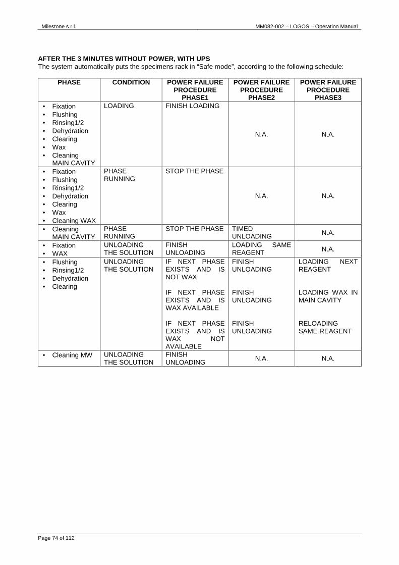
Milestone s.r.l. MM082-002 – LOGOS – Operation Manual
Page 74 of 112
AFTER THE 3 MINUTES WITHOUT POWER, WITH UPS The system automatically puts the specimens rack in “Safe mode”, according to the following schedule:
PHASE CONDITION POWER FAILURE PROCEDURE
PHASE1
POWER FAILURE PROCEDURE
PHASE2
POWER FAILURE PROCEDURE
PHASE3 • Fixation • Flushing • Rinsing1/2 • Dehydration • Clearing • Wax • Cleaning
MAIN CAVITY
LOADING FINISH LOADING
N.A. N.A.
• Fixation • Flushing • Rinsing1/2 • Dehydration • Clearing • Wax • Cleaning WAX
PHASE RUNNING
STOP THE PHASE
N.A. N.A.
• Cleaning MAIN CAVITY
PHASE RUNNING
STOP THE PHASE TIMED UNLOADING N.A.
• Fixation • WAX
UNLOADING THE SOLUTION
FINISH UNLOADING
LOADING SAME REAGENT N.A.
• Flushing • Rinsing1/2 • Dehydration • Clearing
UNLOADING THE SOLUTION
IF NEXT PHASE EXISTS AND IS NOT WAX IF NEXT PHASE EXISTS AND IS WAX AVAILABLE IF NEXT PHASE EXISTS AND IS WAX NOT AVAILABLE
FINISH UNLOADING FINISH UNLOADING FINISH UNLOADING
LOADING NEXT REAGENT LOADING WAX IN MAIN CAVITY RELOADING SAME REAGENT
• Cleaning MW UNLOADING THE SOLUTION
FINISH UNLOADING
N.A. N.A.
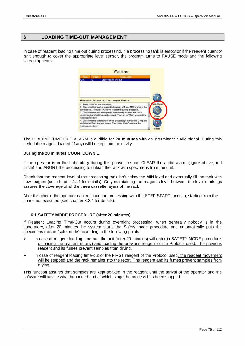
Milestone s.r.l. MM082-002 – LOGOS – Operation Manual
Page 75 of 112
6 LOADING TIME-OUT MANAGEMENT
In case of reagent loading time out during processing, if a processing tank is empty or if the reagent quantity isn’t enough to cover the appropriate level sensor, the program turns to PAUSE mode and the following screen appears:
The LOADING TIME-OUT ALARM is audible for 20 minutes with an intermittent audio signal. During this period the reagent loaded (if any) will be kept into the cavity. During the 20 minutes COUNTDOWN … If the operator is in the Laboratory during this phase, he can CLEAR the audio alarm (figure above, red circle) and ABORT the processing to unload the rack with specimens from the unit. Check that the reagent level of the processing tank isn’t below the MIN level and eventually fill the tank with new reagent (see chapter 2.14 for details). Only maintaining the reagents level between the level markings assures the coverage of all the three cassette layers of the rack After this check, the operator can continue the processing with the STEP START function, starting from the phase not executed (see chapter 3.2.4 for details).
6.1 SAFETY MODE PROCEDURE (after 20 minutes)
If Reagent Loading Time-Out occurs during overnight processing, when generally nobody is in the Laboratory, after 20 minutes the system starts the Safety mode procedure and automatically puts the specimens rack in “safe mode” according to the following points:
� In case of reagent loading time-out, the unit (after 20 minutes) will enter in SAFETY MODE procedure, unloading the reagent (if any) and loading the previous reagent of the Protocol used. The previous reagent and its fumes prevent samples from drying.
� In case of reagent loading time-out of the FIRST reagent of the Protocol used, the reagent movement will be stopped and the rack remains into the retort. The reagent and its fumes prevent samples from drying.
This function assures that samples are kept soaked in the reagent until the arrival of the operator and the software will advise what happened and at which stage the process has been stopped.

Milestone s.r.l. MM082-002 – LOGOS – Operation Manual
Page 76 of 112
The screen will display that Safety Mode Procedure has been activated, with following details:
e) Processing Cycle - protocol name and size f) Date of Loading time-out - when the program stopped g) Phase loading step
When the operator is back in the Laboratory (generally the next morning), he can “Close” the SAFETY MODE PROCEDURE screen, ABORTING the program. The operator can now continue the processing with the STEP START function, starting from the phase not executed (see chapter 3.2.4 for details).

Milestone s.r.l. MM082-002 – LOGOS – Operation Manual
Page 77 of 112
7 MAINTENANCE
7.1 INTRODUCTION Maintenance of LOGOS is carried out at two levels:
The first is at laboratory level: a simple routine maintenance can prevent the likelihood of more serious problems. Minimal routine maintenance is required by laboratory personnel that use LOGOS. The following procedure is recommended to ensure optimal performance of LOGOS:
The second level of maintenance is technically more detailed and is beyond the scope of normal laboratory personnel. The unit requires once a year a technical preventive maintenance to maintain the high performance and prevent any malfunctionality.
Contact annually your local distributor or Mileston e offices directly ([email protected] ) how to perform Preventive Maintenance and regular inspections in order to maintain your LOGOS within safe operative standards.
7.2 AFTER EACH RUN Ensure that LOGOS is generally kept clean after each use. Do not use abrasives or sharp instruments that may damage acid/solvent resistant coating etc.
Clean as soon as possible the rack (by molten wax) after every processing cycle to completely remove the wax. For more details see the paragraph 7.2.1.
Ensure that the wax level is between the MIN and the MAX (wax settings screen). For more details see the paragraph 2.13.
Wipe off the undersurface of the cavities covers when the cassettes rack is unloaded from the wax, on completion of both Processing and Wax/MW cavity cleaning procedures.
Traces of solidified wax may interfere with correct closing of the cavity and may result in vacuum error.
7.2.1 Rack cleaning procedure There are two different ways to correctly clean wax traces away from the LOGOS RACK after processing: FIRST WAY: It is possible to clean the rack inside the processing chamber during a Cleaning cycle with 3 tanks (see the chapter 3.3), after a wax phase of a dual processing, when the wax has been loaded in the main chamber from the wax chamber.
Cleaning the rack outside of the unit is recommende d.

Milestone s.r.l. MM082-002 – LOGOS – Operation Manual
Page 78 of 112
HOW TO OPERATE:
1) After unloading samples, open the main cavity and insert the empty rack to clean, as shown below.
2) Select “Cleaning ” from the main menu and then “Main cavity cleaning ”.
3) Choose from the list your cleaning protocol and then press “OK”.
4) At the end of the cycle, both the rack and the main cavity are clean from wax and a new process can be
started. SECOND WAY (HistosMATE instrument requested):
Xylene to clean the rack is NOT allowed when using the HistosMATE.
Milestone has developed an automatic rack cleaner: the HistosMATE. For further info open our website page www.milestonemedsrl.com or contact our
representative in your country.

Milestone s.r.l. MM082-002 – LOGOS – Operation Manual
Page 79 of 112
7.3 DAILY It’s required to daily check the level of reagents condensed in the three condensation traps. Lift up the frontal panel, as shown below.
As you can see below, the maximum level of liquid is labeled on each condensation trap (see arrow). When the level is near the limit, remove the thumbscrew securing the cooltraps and empty any collected fluids. Then reinsert the condensation traps and secure with thumbscrew. Make sure that the condensed liquid does not go over the limit indicated.
7.4 TWICE A WEEK It’s required to clean the wax in order to extend its reuse life and avoid artifacts related to the impregnation step, as described in the chapter 7.4.1.
7.4.1 Wax cleaning Wax cleaning (it takes 90 minutes): the WAX reuse life has expired (in this case: number of days), a RED icon is shown over the Wax Cavity and the word “Replace” blinks in red (figure below) in the Reagent screen.
It’s suggested to clean the wax twice a week in cas e LOGOS is working once a day without sponges. In any other case, like use of sponges or several runs per day, please contact our Application Dept at [email protected] to get proper instructions.

Milestone s.r.l. MM082-002 – LOGOS – Operation Manual
Page 80 of 112
There are two ways to run a “Wax cleaning” protocol: FIRST WAY: from the reagent screen select “Wax cleaning ”, as shown below.
SECOND WAY: Select “Cleaning ” from the MAIN FUNCTIONS screen and then “Wax cleaning ”, as shown below.
When a wax cleaning cycle has been COMPLETED, the wax values reported in the Reagent Configuration screen (number of cassettes processed, performed cycles and loading date) are RESET to zero.
The DATE of the last cleaning cycle is recorded and reported on the REAGENTS screen (figure below, red circle).
DO NOT load LOGOS rack during the “WAX cleaning pro cedure”.
Wax must be completely replaced (and NOT cleaned) a t least once a month, depending on the use of LOGOS. See the chapter 4.3 for the wax r eplacement procedure.

Milestone s.r.l. MM082-002 – LOGOS – Operation Manual
Page 81 of 112
7.5 WEEKLY Check if there is any residual reagent in the drawer. If you want to empty it, unscrew the cup as indicated in the figure below, put a container under the unit and unload the residual reagent.
CLEANING PROCEDURE FOR CLEANING TANKS
TO BE PERFORMED AFTER EVERY CHANGE OF CLEANING REAG ENTS • Reagents required: Xylene, Isoparaffin or substitute and Ethanol. • Purpose of cleaning: is performed on all CLEANING tanks that have potential contamination from WAX
residues. • When to clean: to be performed EVERY TIME cleaning reagents are changed. • Removal of tanks: remove the pipe and then the tank. Dispose of reagent according to lab practices
appropriate for that reagent. • Cleaning procedure: perform a rinse in Xylene or Isoparaffin or substitute (close tank and shake for a
few minutes), dispose of waste reagents and follow with two quick rinses in Ethanol. • Reinstalling of tanks and reagent replacement: load tanks with fresh cleaning reagents, put the pipe
and then the tank in the drawer. Complete replacement of reagent that resets reagent management counts.
7.6 YEARLY Call your service support for preventive maintenance contract.
It’s required to execute the cleaning procedure when the cleaning tanks are not commercial but either supplied locally or purchased directly from the manufacturer
because it’s possible to reuse them several times.
When the cleaning tanks are severely contaminated o n the basis of their use change them.
Tank xylene proof Ref. P/N 70170F (for details see Chapter 10).
If LOGOS remains OFF for more than a week, when it is turned ON: Check the reagents levels and adjust them if necess ary.
Check WAX deposits in the cleaning tanks and if sev erely contaminated, clean them and replace the reagent.
Check the pipes of the cleaning tanks and, if block ed by solid WAX, put them in an oven to molten it.

Milestone s.r.l. MM082-002 – LOGOS – Operation Manual
Page 82 of 112
7.7 HOW TO START THE REMOTE ASSISTANCE This procedure explains how to activate the Remote Assistance in case of request by Service Department.
It is necessary to connect LOGOS to Internet in order to allow Remote Assistance services (for further details see the chapter 2.6).
In administrator screen, press “Service ” icon to get Service Screen.
Press “Remote Assistance ” to start the connection:
At this point remote service works with your instrument. The Remote Assistance will be disabled by remote service.
Do not disconnect nor restart the instrument during the remote connection.
ALWAYS COMMUNICATE THE SERIAL NUMBER (S.N.) OF THE UNIT. MILESTONE CANNOT CONNECT TO UNIT WITHOUT THE S.N.
THE SERIAL NUMBER IS AVAILABLE IN “ HELP” ICON IN MAIN SCREEN.

Milestone s.r.l. MM082-002 – LOGOS – Operation Manual
Page 83 of 112
8 GOOD TISSUE PROCESSING PRACTICE
Specimens : Size
1. Processing times are a direct function of specimens size. Milestone factory stored protocols are based on following standardized sizes (for standard cassette of 30x25x5mm): • Transplant (<1mm) • 1mm (Small biopsy cylinders of about 1mm diameter) • 2mm (Biopsy 10 x 5 x 2mm) • 3mm (Biopsy 15 x 10 x 3mm) • 4mm (Surgical 20 x 25 x 4mm) • 5mm (Large 30 x 25 x 5mm) • 6mm (Large 30 x 25 x 6mm)
2. As a general rule, user must take in consideration that each additional 1mm thickness will require about
1 hour processing. (for example: 1mm takes 1 hour; 2mm takes 2 hours etc..) 3. Universal biopsy cassette can accommodate up to 5mm thick samples. Make sure that the thickness is
the one specified for the processing protocol selected. Milestone has developed the CheckLITE, a user-friendly, non-contact device that automatically signals with a green light when the specimen is cut at the desired thickness. For further information on CheckLite, contact Milestone srl at [email protected] or your local distributor.
Protocol and Type of specimen
Select the appropriate protocol in relation to the size of specimens to be processed.
1. With Milestone technology, different types of specimens can be simultaneously processed (Kidney, heart, colon, Liver) in the same run. The time at temperature pre-stored protocols are suited for the most sensitive tissue.
2. Specimens with different thickness but all up to 5 mm can be simultaneously run. While the temperature is set for the most sensitive tissue, the processing time is set for the thickest specimen. This means that, if 2, 3, 4 mm thick specimens are to be processed together, the 4mm protocol must be selected.
3. Biopsies of ≤ 1 mm thickness (like renal or gastric biopsies) require separate processing, because of their small size.
Fatty tissues
Fatty tissues are some of the most difficult tissues to process. Milestone has patented a very effective reagent, the JFC solution (Ethanol, Isopropanol and long chain Hydrocarbon) which, in combination with microwaves technology, assures best results. For further information on JFC Solution, contact Milestone srl at [email protected] or your local distributor.
Fixation
Fixation is the all important first step of tissue processing. Tissues that have not been optimally fixed can give bad morphology and processing artifacts. Before starting the Dehydration/clearing steps, tissue must be properly fixed. Fixation can be carried out either using formalin or Milestone formalin-free FineFIX solution. For further information on FineFix, contact Milestone srl at [email protected] or your local distributor. Tissue can be fixed overnight at room temperature. For faster fixation result, Milestone microwave units have a preset protocol. The Microwave time required for each mm of thickness is of about 10 minutes at 50°C.

Milestone s.r.l. MM082-002 – LOGOS – Operation Manual
Page 84 of 112
Beware
The use of inserts like sponges or thick paper or the use of small mesh cassette negatively influences the correct flow of the reagent through the cassette. Use only insert of lens paper or cassette with large mesh to allow proper unobstructed flow of reagent.
The use of Nylon made cassettes (like Mesh Cassettes shown in the picture below) in our microwave units must be avoided. For this reason, we suggest you contact your customer/s to advise that the use of Nylon made cassettes in our microwave units must be avoided.
In the case sponges are used, increasing of the Eth anol, JFC Isopropanol and Wax processing time by half of the preset time is recom mended.
If the Laboratory is already using particular kind of cassettes, please contact either our application support: [email protected] with details of the type of
cassettes utilized, so that we can check whether th ey are suitable to be used in our microwave units.
Lens paper – Biopsy large mesh cassette
YES
Thick paper – Sponges – small mesh cassette
NO
NO

Milestone s.r.l. MM082-002 – LOGOS – Operation Manual
Page 85 of 112
Reagents
Make sure to follow the software reagents’ reuse settings. Check them daily to minimize inconsistent results. Purity of reagents: 1. When the water concentration in the reagents is more than 3% volume, a progressive loss of
dehydrating effect takes place. This problem can be caused by an overshooting limit of “maximum number of cassette to process” or “Max number of processing cycle to use” for the respective reagents.
2. Insufficient cleaning of the rack after processing can contaminate reagents with traces of paraffin. Wax can be reused several times because is left uncontaminated after every protocol. Make sure to follow the software Wax’ reuse settings. Be sure to run the wax cleaning cycle at least weekly. However if the wax is dirty or contaminated by reagents (alcohol smell), it must be replaced.
Milestone has collected some cause/effect scenarios that affect tissue quality:
8.1 MICROWAVE ALCOHOLS QUALITY
Introduction
The purpose of this document is to recommend procedures to overcome issues associated with inconsistency of microwave tissue processing brought about by water contamination of the microwave ethanol, at a few laboratory sites, employing SPONGE BIOPSY PADS.
Background
Feedback from laboratory sites employing a combination of tissue cassettes, with and without sponge biopsy pads, showed that the processing artifacts are a result of water contamination of the microwave ethanol step. Sponge biopsy pad cassettes have the effect of retaining more fluid (formalin) than without sponges and therefore easily raising the water levels in the subsequent alcohol steps. Provided the purity of the microwave ethanol is maintained at least 99%, the next microwave step in Isopropanol can be changed less frequently.
A secondary effect of sponge use is that retention of fluid occurs for other reagents in use and will impact on the process time (under processing) necessitating longer times to remove fluids: in this case, the action would be to select the next longer processing program time available, after the small biopsy program. The quality of tissue processing results is a reflection of effective fixation and quality of reagents used, whether for conventional or microwave processing, noting that even with conventional processors the last alcohol of the processor must be 100% (reagent grade), to avoid processing artifacts. Conclusions:
1. Introduction of sponges into cassettes increases retention of formalin necessitating an additional rinse alcohol step.
2. In view of the pressure that labs work under, there is a need to develop a Standard Operating Procedure (SOP) for inter-lab reproducibility and overcome any ambiguity in lab practices for exchanging of alcohols used.
3. Introduce a qualitative check of the microwave alcohol prior to microwave processing.
Reagents loaded must be 99% reagent grade.

Milestone s.r.l. MM082-002 – LOGOS – Operation Manual
Page 86 of 112
Recommendations:
1. Introduce an extra (third) sequential Rinsing Alcohol (100% Reagent Grade):- as a first rinse in the grossing room, for accumulating wet tissue cassettes containing sponge biopsy pads for processing.
2. ETHANOL REPLACEMENT every TWO full runs when using sponge biopsy pads (worst case scenario).
4. ISOPROPANOL REPLACEMENT at every THIRD run.
5. Use the NEXT SIZE up processing time program, when dealing with sponges present in cassettes, to avoid under processing.
8.2 TISSUE PROCESSING SELECTION GUIDELINES Ethanol - Isopropanol - Wax
1. Ethanol-Isopropanol recommended as the standard routine method for small to medium-large size biopsies.
2. Fat content of the tissue is kept to a minimum (< 2mm thickness).
3. Very Cost effective for general tissue-processing.
4. Strongly recommended for processing of Renal/Gastric, breast core biopsies and equivalent tissue size.
JFC – Isopropanol - Wax
1. JFC - ISO sequence is strongly recommended for high fat content such as Breast / Lipoma up to full size cassette in less than 4 hours.
PROWAVE - Wax
1. PROWAVE is a “one step” solution that can be used for tissues where overnight fixation time is uncertain, since PROWAVE can also act as a secondary fixative.
2. Ideally suited for non-fatty tissues (up to 5 mm thick) or moderate lipid content tissues (up to 3 mm thick).
Ethanol - JFC - Wax
1. Ethanol–JFC for tissues where overnight fixation of tissue is uncertain and or partially fixed tissues.
2. Ethanol acts as a secondary fixative step since JFC is not a fixative.
3. Especially suited for routine use and for very fatty tissues admixed with normal parenchyma.
4. Ethanol step will extend the reuse life of the JFC.
JFC - Wax
1. JFC solution is strongly recommended for tissues known to be well fixed, generally at least overnight.
2. Ideally suited for tissues containing a high lipid content, e.g. skin and brain admixed with normal parenchyma.

Milestone s.r.l. MM082-002 – LOGOS – Operation Manual
Page 87 of 112
TISSUE PROCESSING SELECTION GUIDELINES
Washing in Ethanol 1 min
FRESH RENAL BIOPSIES
Soaking in Formalin up to 30 min.
Microwaving in Formalin 5 min. ramping time to 50°C
10 min. holding at 50°C
Ethanol 100% - 10 min total time.
Isopropanol 100% - 10 min total time.
WAX 15-20 min.
PARTIALLY FIXED TISSUE BLOCKS
FIXED TISSUE
10/20’: Small biopsy
30’: 3mm
60’: 5mm
Microwave Fixation complete phase
FRESH TISSUE
30’: Small biopsy
1 hr: 3mm
1.5 hr: 5mm
2/3 hrs:5mm breast/fatty tissues
Soaking in Formalin with agitation
Rinsing in Ethanol
Ethanol JFC
Isopropanol
Routine method
Fatty tissues
ProWave (o JFC)
One step routine
Isopropanol
WAX
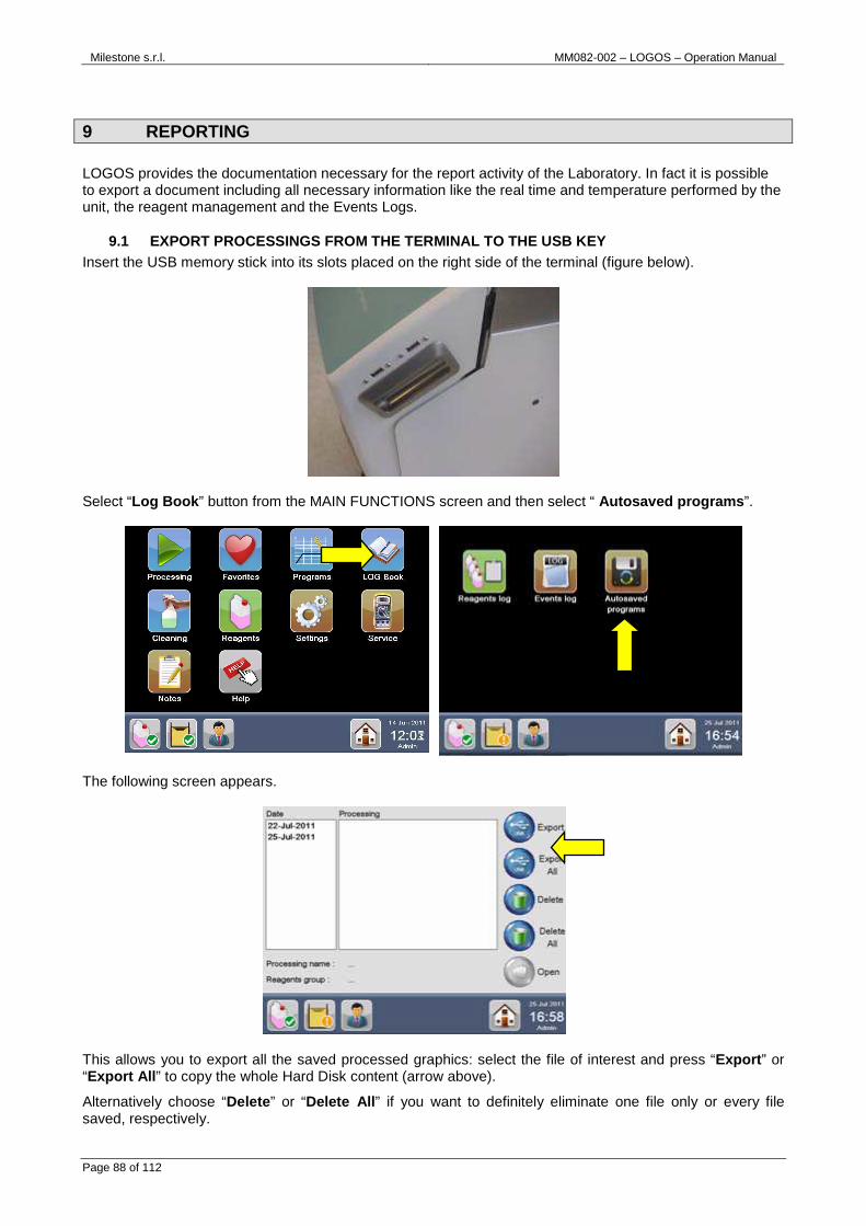
Milestone s.r.l. MM082-002 – LOGOS – Operation Manual
Page 88 of 112
9 REPORTING LOGOS provides the documentation necessary for the report activity of the Laboratory. In fact it is possible to export a document including all necessary information like the real time and temperature performed by the unit, the reagent management and the Events Logs.
9.1 EXPORT PROCESSINGS FROM THE TERMINAL TO THE USB KEY Insert the USB memory stick into its slots placed on the right side of the terminal (figure below).
Select “Log Book ” button from the MAIN FUNCTIONS screen and then select “ Autosaved programs ”.
The following screen appears.
This allows you to export all the saved processed graphics: select the file of interest and press “Export ” or “Export All ” to copy the whole Hard Disk content (arrow above).
Alternatively choose “Delete ” or “Delete All ” if you want to definitely eliminate one file only or every file saved, respectively.

Milestone s.r.l. MM082-002 – LOGOS – Operation Manual
Page 89 of 112
9.2 INSTALL AND OPERATE WITH THE LOGVIEWER The USB key provided with the unit contains the LogViewer folder. Double click on the “SetupLogViewer.exe” icon to install the program. The LogViewer software is now ready to work. Microsoft.NET Framework 4.0 is a prerequisite to this application, the setup will install it if not present on your PC. Christal Report Runtime is a prerequisite to this application the setup will install it if not present on your PC.
9.2.1 Open process Plug the USB memory stick on the LOGOS terminal where all processes are stored and export them on the key, as described in chapter 3.4. • Open the LogViewer software (go to “Start Menu\All programs\Milestone srl\Milestone LogViewer” or click
on the “LogViewer” icon created on your desktop). • Plug the USB key in your PC and “Open” a process by clicking on the relative icon (green circle).
• Select the USB folder with saved processes of interest (see the example below).
• “The Milestone process Log File is compressed. Do you want to decompress and open it?”. Press yes to this message to proceed.
• Now all the process phases are shown. Data available are listed in the following fields:
� PROCESS INFO: all details of that process. � PHASES: all details of different phases. Click on "Show step list" for details of the selected STEP
(green circle). � GRAPH LINES: info and selection.

Milestone s.r.l. MM082-002 – LOGOS – Operation Manual
Page 90 of 112
• For an enlarged view of a processing curve, click directly on it (blue circle figure above). • Click on “Prev Phase” or “Next Phase” arrow (red circles figure below) to view phases before or after it
respectively.

Milestone s.r.l. MM082-002 – LOGOS – Operation Manual
Page 91 of 112
9.2.2 Print process
• Preview/printing of the curves is possible by selecting the “Print” icon (green circle).
• Select the appropriate printing format from the drop down menu:
� Print summary: this print preview includes all phases (without graphs) with process and unit information.
� Print current phase: this print preview includes phase selected with process and unit data. � Print full process: this print preview includes all phases (with graphs) with process and unit
information. • When the print preview required has been selected, click on the “Print” icon from the bar in the upper left
of the preview page (green rectangle).
Enlarged view of the “Print” icon from the bar in the upper left of the preview page.

Milestone s.r.l. MM082-002 – LOGOS – Operation Manual
Page 92 of 112
9.2.3 Send process to customer support (Milestone)
• Click on the icon “Send process to customer support” (green circle) to forward an automatic message to Milestone customer support e-mail.
• This message opens: • Press OK and check your e-mail, a preset message appears with the following information:
� TO: [email protected] � OBJECT: Milestone UNIT NAME (Serial number) � TEXT: To Milestone Customer Support...
• Just send the e-mail.

Milestone s.r.l. MM082-002 – LOGOS – Operation Manual
Page 93 of 112
9.2.4 Change settings • Select “Settings” icon (green circle), to change the settings configuration.
• All settings are displayed as follows:
� Graph style: modify the color of the X/Y axes, show/hide the grid, get axes displayed as dotted. � Process curves style: modify color and thickness of the Pre-set and Real values lines (temperature
and power). � Printing options: modify pages header.
9.2.5 Other functions
1. About Milestone LogViewer 2. View help (HOW TO) 3. Exit Application
1 2 3

Milestone s.r.l. MM082-002 – LOGOS – Operation Manual
Page 94 of 112
10 LOGOS OPTIONAL ACCESSORIES
Not included, to be ordered apart: • n° 1 Tank 5 liters capacity (Ref. P/N 70170),
• n° 1 Tank 5 liters capacity Xylene proof (Ref. P/N 70170F), • n°1 UPS module (Ref. P/N 66100), Option valid only for units at 230V – 50/60Hz (for further details see
the chapter 2.5.5),
• n°1 Rack for up to 24 Supermega Cassettes on 2 lay ers for Pathos Delta (Ref. P/N 66130),
• n°1 High Volume Basket Rack for up to 300 standard cassettes on 3 layers, suitable for overnight processing, for Pathos Delta (Ref. P/N 66140),

Milestone s.r.l. MM082-002 – LOGOS – Operation Manual
Page 95 of 112
• n°1 External exhaust fumes filter kit, including o ne spare filter (Ref. P/N 61550),
Fan air flow range:50–55m3/h (cube meter per hour).
CHANGE THE CHARCOAL FILTER:
1. Open the six black knobs from the carter. 2. Then remove the filter’s chassis. 3. Now remove the black seal. 4. Remove the filter. 5. Replace the filter with the new one, place the black seal. 6. Close the chassis of the carter and screw the six knobs.
1 2 3
4 5 6
The external fume extraction system must be properl y installed at all times, according to local regulations on the safety of laboratory in fo rce.
The external fume extraction system must permit an air flux 55m 3/h (cube meter per hour).
In case your LOGOS is connected to an external fume extractor or to a fume hood, the filter should be changed EVERY YEAR.
Otherwise, if there is no external extractor, we re commend to change it EVERY 6 MONTHS.

Milestone s.r.l. MM082-002 – LOGOS – Operation Manual
Page 96 of 112
• n°1 Luminous tower (Ref. P/N 61540 for further det ails see the chapter 2.6).
A B
C D E
RED LIGHT BLINKING : a generic alarm is occurring, operator has to check the unit to solve the problem. GREEN LIGHT ON: the program is over, operator can extract samples and start another cycle. Parts of the system:
A. Luminous tower, box socket and connector. B. Power supply. C. Main cable 230V. D. Main cable 115V. E. Cable for connection with UPS.

Milestone s.r.l. MM082-002 – LOGOS – Operation Manual
Page 97 of 112
A. APPENDIX
A.1. MW TISSUE PROCESSING TROUBLESHOOTING GUIDE
PROBLEM BLOCK/SLIDE POSSIBLE CAUSES RIMEDIAL ACTION
Pyknotic nuclei and severe cytoplasmic distortion of the tissue section. Poor dehydration. Tissue sections have the microscopic appearance of pyknotic nuclei and severe cytoplasmic distortion (overheated appearance). Opaque white surface appearance and softness of some areas of the block after the trimming.
1. Tissue has been poorly fixed and
processed exclusively with JFC solution (JFC is NOT a fixative).
2. Water contamination of microwave
ethanol step due to carry over of water from rinsing alcohols or the quality of ethanol in use with microwave is less than 100% (poor dehydration).
3. Water carry over is increased in rinsing
alcohols by the use of sponge biopsy pads (poor dehydration).
4. For small biopsy samples: inadequate
dehydration due to use of paper wraps that restricts the flow of reagents. For larger biopsies: processing time selected is inadequate for dehydration.
5. Additives used in some commercial
formalin fixative preparations interfere with JFC, even though tissues are well fixed in formalin (rare occurrence).
1. Tissues to be fixed overnight in formalin, if
using JFC exclusively. Introduce an ethanol microwave step to post fix tissues with ethanol, prior to using JFC. OR Use Ethanol-Isopropanol processing.
2. Replace used microwave ethanol with fresh
100% ethanol (pure or reagent grade). AND Implement regular checks of ethanol with a Hydrometer, to ensure that microwave ethanol is 100% quality (water free).
3. Introduce an extra (third) ethanol rinse to
ensure sponge pads are well cleansed.
4. For small biopsies with biopsy wraps: do not use the small biopsy run but instead increase the processing time in the ethanol and Isopropanol to compensate for the wraps restricting reagent flow. AND For larger samples sizes: increase the processing time.
5. Introduce an ethanol microwave step to wash
out the contaminants from the tissues, prior to using JFC.

Milestone s.r.l. MM082-002 – LOGOS – Operation Manual
Page 98 of 112
PROBLEM BLOCK/SLIDE POSSIBLE CAUSES RIMEDIAL ACTION
Specimens partially or completely detached from surrounding WAX. Tissue block surface appears to collapse “Dry back” and samples appear partially or completely detached from surrounding WAX when the tissue is observed the next day. Tissue block very difficult to section.
1. Processing time is inadequate for the
tissue size selected, resulting in incomplete dehydration/clearing and WAX impregnation.
Tissues that retain any of the solvent will escape by next day, producing this effect, varying according to the size.
1. Select the correct processing time, or
select longer processing time for the sample size.

Milestone s.r.l. MM082-002 – LOGOS – Operation Manual
Page 99 of 112
PROBLEM BLOCK/SLIDE POSSIBLE CAUSES RIMEDIAL ACTION
Inadequate Clearing of fat. The block face has a “greasy” feeling. Tissue block difficult to section. When section placed on water bath the section breaks up. Softness of some areas of the block after the trimming.
1. Processing time for tissue is
inadequate for the size selected, resulting in incomplete removal of fats, especially from fatty specimen blocks, such as breast. This can be seen when processing the larger blocks, where processing times become more critical to accommodate the larger sizes.
2. Use of isopropanol as clearing agent for fatty tissues is inefficient for the removal of fats, especially the larger blocks of breast.
3. Reuse life of dehydration or clearing reagent has been exceeded.
1. Select the correct processing time, or select
longer processing time for the sample size. AND Reduce tissue thickness when preparing wet tissue blocks, if reducing processing times is not desired.
2. Use JFC as the alternative clearing agent. AND Significantly reduce tissue block thickness (50%) as well as increase WAX impregnation time (compromise method, not recommended as it may be impractical to implement routinely).
3. Replace the dehydration/clearing reagent or reduce the number of times the solution is reused.

Milestone s.r.l. MM082-002 – LOGOS – Operation Manual
Page 100 of 112
PROBLEM BLOCK/SLIDE POSSIBLE CAUSES RIMEDIAL ACTION
Collapse of block upper face after sectioning. Tissue block surface appears to collapse “Dry back” when the tissue is observed the next day. This occurs even though a section of the block have been easily cutted the previous day. Tissue block not difficult to section the same day.
1. Tissue has been sufficiently
dehydrated and cleared (dry tissue) allowing sections to be cut, however WAX impregnation is not entirely complete with residual amounts of the previous solution remaining.
Indicated by continued bubbling originating from the tissue blocks in the final stage (near the end) of the WAX program. Does not occur in smaller blocks, but may appear as tissues increase in size. The result is that tissues that retain any of the solvent will escape by next day, producing this effect, varying according to the size.
1. Retrospectively increase WAX impregnation
time by melting the block down and placing it into molten WAX in a WAX oven for convenience. At least an hour. AND Prospectively increase standard WAX impregnation times. Approx. 30 minutes for the longest processing program. For the shorter processing programs approximately 15 minutes increase in WAX time.

Milestone s.r.l. MM082-002 – LOGOS – Operation Manual
Page 101 of 112
PROBLEM BLOCK/SLIDE POSSIBLE CAUSES RIMEDIAL ACTION
White appearance of block face. Tissue block surface looks unprocessed after trimming the block (opaque white surface). Section can be easily cut and when placed on water bath it does not explode. “DRY” feel of block face in unprocessed areas, usually in the centre of the larger blocks.
1. Tissue has been sufficiently
dehydrated and cleared (dry tissue), however WAX impregnation is not complete.
Indicated by continued bubbling originating from the tissue blocks in the final step of the WAX program. Can be seen when processing larger blocks, where times become more critical to accommodate the larger sizes.
1. Retrospectively increase WAX impregnation
time by melting the block down and placing it into molten WAX in a WAX oven for convenience. AND Increase standard WAX impregnation times for future processing runs.

Milestone s.r.l. MM082-002 – LOGOS – Operation Manual
Page 102 of 112
PROBLEM BLOCK/SLIDE POSSIBLE CAUSES RIMEDIAL ACTION
Pigment deposits in microscopic section. Microscopic picture shows pigment deposits (black/brown) at sites of hemorrhagic deposits (Blood vessels, Spleen and products of conception).
1. Hemorrhagic tissue that has not been
adequately fixed (stabilized) will display deposits of formalin pigment at sites where there are abundant red blood cells.
Present in tissues with hemorrhagic sites such as major blood vessels, where there are abundant red blood cells and related breakdown deposits, this especially includes the Spleen.
1. Confirm that the pigment is actually formalin
pigment and not hemosiderin (Iron break down products of red blood). AND To remove pigment retrospectively, if it interferes with diagnosis, then use the standard formalin pigment removal treatment method that uses Picric Acid. AND Prospectively, to avoid this from occurring is to ensure that hemorrhagic tissue is well fixed before by microwave fixation or conventional fixation, before microwave processing.

Milestone s.r.l. MM082-002 – LOGOS – Operation Manual
Page 103 of 112
PROBLEM BLOCK/SLIDE POSSIBLE CAUSES RIMEDIAL ACTION
Fatty tissue collapses in block and microscopic section. Macro : fatty tissue block structure size looks much smaller than the original piece placed in the cassette (appears collapsed). Micro : the fatty section does not that honeycomb appearance of fatty cells and instead the fat cells are collapsed into themselves (squashed together).
BEFORE
AFTER
1. Tissue size is too large for adequate
fixation to occur and stabilize the tissue to withstand subsequent exposure to reagents, such as JFC.
2. Present in larger fatty tissue blocks
where there is an absence of connective tissue parenchyma to hold fat cells in place: connective tissue provides a framework to support fatty cells in place.
More likely to be seen in larger fatty tissue blocks and not in smaller fatty biopsies such as breast core biopsies.
1. Ensure that tissue fixation for the larger tissue
blocks has been performed conventionally for at least overnight, or with microwave fixation prior to microwave processing: don’t assume tissue is well fixed when dealing with larger size samples. AND If using JFC as the only processing agent, then change to a program that utilizes JFC followed by Isopropanol, where Isopropanol helps stabilize fatty cell structure.
2. Use of Isopropanol as the last reagent step
before WAX infiltration will reduce the risk of fatty cell collapse, so a preset protocol for fatty tissue should employ Isopropanol or ProWave as the last reagent step prior to WAX infiltration

Milestone s.r.l. MM082-002 – LOGOS – Operation Manual
Page 104 of 112
A.2. OVERVIEW OF MICROWAVE HISTOPROCESSING TROUBLE SHOOTING Problem Cause Remedy
Poorly fixed. �Extend fixation time. Pyknotic nuclei and severe cytoplasmic distorsion Poor fixation/JFC reaction. �Use JFC/Isopropanol program.
Alcohol contamination (water). �Replace alcohol. Use of sponge Pads/ inefficient biopsy Pads. �Extend processing time.
�Use sponge alternatives.
Poor Dehydration
Processing cycle too short. �Use appropriate size processing cycle. Specimens detached from surrounding WAX Processing cycle too short. �Use appropriate size processing cycle.
�Reduce tissue block thickness. Processing cycle too short. �Use appropriate size processing cycle.
�Reduce tissue block thickness. Isopropanol inefficient for fat clearing. �Use JFC as alternate clearing agent.
�Reduce tissue block thickness.
Incomplete Clearing of fat
Dehydration/Clearing agent reuse life exceeded. �Replace Dehydration or Clearing reagent. Collapse of block face after sectioning WAX infiltration not entirely complete. �Increase WAX infiltration time. White appearance of block face WAX infiltration not entirely complete. �Increase WAX infiltration time. Pigment deposit in sections Incomplete fixation of blood. �Perform pigment test to exclude whether formalin
pigment or hemosiderin deposits. �Include MW fixation or extend conventional fixation time.
Inadequate fixation of tissue, reacting with JFC. �Fix tissue conventionally overnight or include MW fixation. �Use JFC followed by Isopropanol protocol for processing.
Fatty tissue collapse in blocks & microsections
Absence of connective tissue parenchyma to support delicate fatty network structure.
�Use JFC followed by Isopropanol protocol for processing.

Milestone s.r.l. MM082-002 – LOGOS – Operation Manual
Page 105 of 112
B. APPENDIX
B.1. HOW TO MANAGE AN ALARM
CODE DESCRIPTION WHAT TO DO 1 Communication fault
2 Watch dog fault
11 Rotary valve time out
1. Press 'Clear' to reset the alarm. 2. Reboot the system (wait 2 minutes before the rebooting). 3. Call your customer service if the issue can’t be fixed and press 'Help
Desk' to manage specimens while the Alarm is occurring.
12 Load reagent time out 1. Press 'Silent' to hide the alarm. 2. Check that the volume of reagent in the tank is enough to reach the
level sensor according to the configuration chosen. Then press 'Clear' to repeat the loading procedure.
3. Check that the reagent tanks are rightly inserted (hoses correctly inserted in the tanks). Then press 'Clear' to repeat the loading procedure.
4. Check that the reagent tanks are well cleaned from any salts deposits on the bottom of them. Then press 'Clear' to repeat the loading procedure.
5. Check that the reagent tank hoses are not bent or occluded by anything. Then press 'Clear' to repeat the loading procedure.
6. Check that the hose connector is clean and properly inserted. Then press 'Clear' to repeat the loading procedure.
7. Call your customer service if the issue can’t be fixed and press 'Help Desk' to manage specimens while the Alarm is occurring.
13 Unload reagent time out 1. Press 'Silent' to hide the alarm. 2. Check that the bottom of the cavity (drainage hole) is not occluded
by anything. Then press 'Clear' to repeat the unloading procedure. 3. Check that the reagent tanks hoses are not bent or occluded by
anything. Then press 'Clear' to repeat the unloading procedure. 4. Check that the hose connector is clean and properly inserted. Then
press 'Clear' to repeat the unloading procedure. 5. Call your customer service if the issue can’t be fixed and press 'Help
Desk' to manage specimens while the Alarm is occurring. 14 Main cavity cover open 1. Press 'Silent' to hide the alarm.
2. Check that the main cavity cover is properly closed. Then press 'Clear’.
3. Call your customer service if the issue can’t be fixed and press 'Help Desk' to manage specimens while the Alarm is occurring.
15 Wax cavity cover open 1. Press 'Silent' to hide the alarm. 2. Check that the wax cavity cover and work area cover are properly
closed. 3. Call your customer service to fix the issue and press 'Help Desk' to
manage specimens while the Alarm is occurring. 17 Cavity fan not running 18 Tanks fan not running 19 Stirrer main cavity not
running 20 Stirrer wax cavity not
running
1. Press 'Clear' to reset the alarm. 2. Press 'Silent' to hide the alarm. 3. Call your customer service if the issue can’t be fixed and press 'Help
Desk' to manage specimens while the Alarm is occurring.
21 Main power is missing 1. Press 'Silent' to hide the alarm. 2. Check that the unit power cable is correctly plugged. 3. Check the power line voltage of the laboratory and compare it with
the voltage required by the instrument (see back label). Voltage must be the same (±10%) of that indicated on this label.
4. Check the Fuses (service operation only). 5. Call your customer service to fix the issue and press 'Help Desk' to
manage specimens while the Alarm is occurring.

Milestone s.r.l. MM082-002 – LOGOS – Operation Manual
Page 106 of 112
CODE DESCRIPTION WHAT TO DO 22 Target sensor error
39 Reagent level too low
1. Press 'Silent' to hide the alarm. 2. Check that status of the target sensor/level sensors, if necessary
clean them. Then press 'Clear' to reset the alarm. 3. Call your customer service to fix the issue and press 'Help Desk' to
manage specimens while the Alarm is occurring. 31 Main cavity temperature
too high
35 Wax temperature too high
1. Press 'Silent' to hide the alarm. 2. Check the presence and rotation of the stirrer. 3. Wait at least 20 minutes and then press 'Clear'. 4. Check the cleaning of the MAIN/WAX cavity. The temperature
sensor might be dirty. 5. Call your customer service if the issue can’t be fixed and press 'Help
Desk' to manage specimens while the Alarm is occurring.
32 Main cavity temperature too low
36 Wax temperature too low
1. Press 'Silent' to hide the alarm. 2. Verify if the Ramping part of the curve has been shortened. Refer to
a factory program to set the correct value. 3. Check the cleaning of the MAIN/WAX cavity. The temperature
sensors might be dirty. 4. Check the power line voltage of the laboratory and compare it with
the voltage required by the instrument (see back label). Voltage must be the same (±10%) of that indicated on this label.
5. Call your customer service if the issue can’t be fixed and press 'Help Desk' to manage specimens while the Alarm is occurring.
33 Main cavity vacuum not Enough
37 Wax vacuum not enough
1. Press 'Silent' to hide the alarm. 2. Check that the undersurface of the main/wax cavity cover and its
O-ring are well cleaned from any wax traces. Then press 'Clear'. 3. Check that the main/wax cavity cover is correctly positioned over the
MAIN/WAX cavity. Then press 'Clear'. 4. Open the front door and check the three cooltraps, they must be
empty and correctly fixed. Then press 'Clear'. 5. Check the status of the wax, it might be highly contaminated by
Isopropanol residuals. Clean the wax or replace it if heavily dirty. 6. Verify if the set vacuum value is not lower then 150mBar, the
instrument cannot correctly follow the pre-set curve. Refer to a factory program to check the value.
7. Call your customer service if the issue can’t be fixed and press 'Help Desk' to manage specimens while the Alarm is occurring.
34 Main cavity vacuum too much
38 Wax vacuum not enough
1. Press 'Silent' to hide the alarm. 2. Wait at least 5 minutes and then press 'Clear'. 3. Call your customer service to fix the issue and press 'Help Desk' to
manage specimens while the Alarm is occurring.
40 Mw leakage sensor high threshold
41 Mw leakage sensor low threshold
1. Press 'Silent' to hide the alarm. 2. Check the presence of reagent inside the cavity. 3. Verify if you have loaded a non-polar reagent (Xylene, Isoparaffin). If
so, the microwaves cannot heat the reagent and are reflected inside the MAIN cavity. Change the reagent type or eventually set a different heating modality ('Resistance heating' in case of Xylene).
4. When possible, check the cleaning of the level sensors and eventually clean them from any wax traces or other deposits.
5. Call your customer service if the issue can’t be fixed and press 'Help Desk' to manage specimens while the Alarm is occurring.

Milestone s.r.l. MM082-002 – LOGOS – Operation Manual
Page 107 of 112
C. APPENDIX
C.1. HOW TO MANAGE SAMPLES WHILE AN ALARM IS OCCURR ING
1. Never leave samples in open air or under fume hood, to avoid drying
2. Put samples as quickly as possible into an external container with one of the following reagent in a quantity sufficient to cover all samples:
Either ETHANOL (90-100%) or ISOPROPANOL
3. Check the wetness level of at least 10% of samples (in different parts of the rack). If wetness level appears:
(*) If necessary, contact your local customer support
GOOD WITH NO DOUBTS
A. Let samples in reagent.
B. Check the step when the emergency situation occurred.
C. Check if the unit can be used for a new cycle (*).
D. Follow the instructions on how to resume an interrupted cycle and restart the cycle with samples using step start procedure.
E. For Logos see chapter 3.2.4 operation manual.
Select the correct step to start from in the following table:
NOT GOOD
A. Follow the recovery laboratory internal protocols for air dried samples.
If not available, follow Milestone suggested recovery protocol.
B. Check if the unit can be used for a new cycle (*).
C. Restart the processing cycle.

Milestone s.r.l. MM082-002 – LOGOS – Operation Manual
Page 108 of 112
If samples have been put in formalin while checking of the unit, it is necessary to start from the rinsing steps.
ALARM OCCURRED
DURING THE FOLLOWING
PROCESSING STEP
STEP START. RESTART FROM:
• LOADING FIXATIVE
• FIXATION
Fixation step (fixation uncertain)
• UNLOADING FIXATIVE
• LOAD/UNLOAD RINSING
• RINSING
Rinsing or Ethanol step if at least one rinsing
step has been performed
• LOADING ETHANOL
• ETHANOL
Ethanol step
• UNLOADING ETHANOL
• ISOPROPANOL
Isopropanol step
• UNLOADING ISOPROPANOL
• VAPORIZATION
Wax impregnation step
• MOVING SAMPLES TO WAX
• WAX IMPREGNATION
Wax impregnation step
MILESTONE SUGGESTED RECOVERY PROTOCOL
FOR AIR DRIED SAMPLES
1. Absolute alcohol 2 changes, 1 hour each
2. 95% alcohol 2 changes, 1 hour each
3. Running tap water for 30 minutes
4. Place in formol-glycerol solution (*) until tissue become soft and pliable with gentle pressure. Tissues may remain in formol-glycerol for up to 8 hours without adverse results.
5. Reprocess on tissue processor in usual manner.
If samples have been put in paraffin , it is necessary to start with the dewaxing step:
Xylene, 3 changes, 1 hour each
Formol-Glycerol Working Solution:
Formalin- Sodium Acetate, (Stock) 90ml
Glycerin (Glycerol) 10ml
Formal-Sodium Acetate (Stock):
Formaldehyde, 38-40% 10ml
Sodium Acetate 2.0 gm
Tap Water 90ml
(*) Should Formol-Glycerol not be available, use tap water, even if the quality of the recovery is lower.


Milestone Srl - via Fatebenefratelli 1/5 - 24010 Sorisole (BG) - ItalyPhone +39 035 4128264 - Fax +39 035 575498e-mail: [email protected] - web: www.milestonemedsrl.com
MILESTONEH E L P I N GP A T I E N T S