Embed Size (px)
Citation preview
4272 IEEE TRANSACTIONS ON ELECTRON DEVICES, VOL. 64, NO. 10, OCTOBER 2017
Microwave Power System Based ona Combination of Two Magnetrons
Yi Zhang, Kama Huang, Senior Member, IEEE, Dinesh K. Agrawal, Tania Slawecki,Huacheng Zhu, and Yang Yang
Abstract— Currently, microwave energy is utilized formany diverse industrial applications because of its variousadvantages including its eco-friendliness. Low-cost, high-efficiency, and high-power industrial microwave sourcesare in urgent demand. In this paper, we propose a low-cost quasi-coherent power-combining system based on acombination of two magnetrons. We have analyzed andbuilt a low-loss waveguide-based applicator combined withspecific phase. This system utilizes the coupling of thecombiner to quasi-lock the slave magnetron. A waveguidephase shifter lies in the slave magnetron branch to adjustthe phase difference between the master and slave mag-netrons’ signals to achieve high resultant efficiency. Basedon theory, the phase difference between the master and theinjected slave magnetrons has been numerically calculatedand analyzed. The phase difference changes periodicallywhen the slave magnetron is quasi-locked to the mastermagnetron and the periodicity increases with the injectionratio. Experimental results show the resultant efficiency ofthe proposed system can reach as high as 92% when usingseveral suitable waveguide components. The investigationalso provides guidelines for further microwave power com-bination systems with multiple sources.
Index Terms— Injection locking, magnetron, microwavepower combining.
I. INTRODUCTION
DEMAND for high-power microwave systems is increas-ing because of environmental concerns. Microwave
energy is increasingly applied to industrial applications suchas plasma lighting, environmental engineering, and materialprocessing [1]–[4]. However, the lack of highly efficient,low-cost, and long-life microwave sources is one of the mainproblems that limit the development of microwave industrialapplications. A magnetron, whose efficiency exceeds 80% and
Manuscript received June 7, 2017; revised July 24, 2017; acceptedAugust 3, 2017. Date of current version September 20, 2017.This work was supported in part by the National Natural Sci-ence Foundation of China under Grant 61501311 and in part bythe Major State Basic Research Development Program of China(973 Program) under Grant 2013CB328902. The review of this paperwas arranged by Editor Manfred Thumm. (Corresponding author:Yang Yang.)
Y. Zhang is with the College of Electronics and Information Engineering,Sichuan University, Chengdu 610065, China, and also with the Materi-als Research Institute, Pennsylvania State University, University Park,PA 16802 USA.
K. Huang, H. Zhu, and Y. Yang are with the College of Electronics andInformation Engineering, Sichuan University, Chengdu 610065, China(e-mail: [email protected]).
D. K. Agrawal and T. Slawecki are with the Materials Research Institute,Pennsylvania State University, University Park, PA 16802 USA.
Color versions of one or more of the figures in this paper are availableonline at http://ieeexplore.ieee.org.
Digital Object Identifier 10.1109/TED.2017.2737555
is available at low cost (compared to Klystrons and others),is very desirable for many industrial applications [5]. However,a single magnetron is power limited since the cavity sizeis limited by the operational frequency. 100-kW magnetronsare possible at 915 MHz, while at 2.45 GHz, high-powermagnetrons can be up to only 20 kW [6], [7]. The cathode of amagnetron is one of the key factors which determines the out-put power and lifetime of the magnetron tubes. The long-lifecathode for the low-power continuous-wave magnetron is welldeveloped, while the cathode for the high-power continuouswave magnetron is still under development [8], [9]. Therefore,a system based on the idea of combining magnetrons is aquite suitable way to address such problems. This “combiningmagnetrons” approach provides a solution for a high-power,low-cost, and long-lifetime microwave source.
It is well-known that every magnetron operates at aslightly different frequency [10]–[12]. The output phaseof the magnetron is random every time it starts operat-ing [13]. To solve the frequency and phase discrepancy prob-lem, a widely applied approach is external-injection locking,which has attracted wide interest since Adler [14] first pro-posed the model of external injection locking on oscillators.Subsequently, the model of injection-locking magnetrons hasbeen further developed with consideration of the pushingand pulling effect [10], [15]. In recent years, the external-injection locking magnetrons, as phase controlled sources,have been developed because of the increasing demand forhigh-power microwave sources [13], [16]–[21]. However,the external-injection method requires an external solid-statedriver which is high-cost, fragile, and power-limited [12], [13].To seek novel approaches, some prior experiments on master-slave injection magnetrons’ power combining have beenconducted [22]. However, the system is complex and costlysince it “extracts” part of the power from the master magnetronto lock the slave magnetron through external injection.
In this paper, we propose a novel low-cost power-combiningsystem as shown in Fig. 1. The system utilizes the cou-pling of the power combiner to lock (or quasi-lock) theslave magnetron. After the frequency of the slave magnetronis dragged to that of the master magnetron, high resultantefficiency can be attained by adjusting the two coherent (orquasi-coherent) signals to approach in-phase. Based on the-ory, the phase difference between the master-slave injectionmagnetrons have been numerically calculated and analyzed.The resultant efficiency of the two magnetrons and the phaserelationships in the system have also been demonstrated.The low-loss combiner has been designed, constructed,
0018-9383 © 2017 IEEE. Personal use is permitted, but republication/redistribution requires IEEE permission.See http://www.ieee.org/publications_standards/publications/rights/index.html for more information.
ZHANG et al.: MICROWAVE POWER SYSTEM 4273
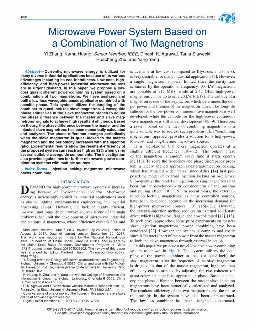
Fig. 1. Schematic of the proposed microwave power-combining system.The coupling signal from the master magnetron is injected to the slavemagnetron to drag the output frequency of the slave magnetron to thefrequency of the master magnetron. Through proper design, the powerfrom both the master and slave magnetrons goes to load2 in almost thesame phase, thus resulting in high resultant efficiency.
and tested. The experimental results from testing the powercombining system are in accord with the theoretical predic-tions. The highest resultant efficiency reaches as high as 92%with the low-cost essential components.
II. THEORETICAL ANALYSIS
A. Loss-Free Power Combiner
To minimize the power loss, a three port, theoretically loss-free power combiner whose S-parameter is shown in (1), hasbeen designed and implemented. In (1), α, β, and γ arethe phase of the reflection in ports 1, 2, and 3, respectively.Ports 1 and 2 are the two input ports of the combiner andport 3 is the output port
S =
⎡⎢⎢⎢⎢⎢⎢⎢⎣
1
2e jα 1
2e jβ
√2
2e jγ
1
2e jβ 1
2e jα
√2
2e jγ
√2
2e jγ
√2
2e jγ 0
⎤⎥⎥⎥⎥⎥⎥⎥⎦. (1)
For a theoretically loss-free component, its S-matrix needsto satisfy the following equation:
[S][S]∗t = [U ] (2)
where the superscripts ∗ and t indicate conjugate and transposeof the S matrix, respectively, [U ] is the unit matrix [23].Solving (2), we can get the following phase relationship:
(α − β) = (2k + 1)π. (3)
Since a three-port device by itself cannot be loss-free, recip-rocal, and matching at the same time [23], we designed atheoretically loss-free, reciprocal waveguide power combinerto minimize the power loss of the system. The output portof the power combiner is well-matched because it connectsto the load. The two input ports are not well-matched andcoupling between the two input ports also exists. As mentionedabove, the output frequency of each magnetron is slightlydifferent and the output phase is random every time themagnetron starts working [10]–[13]. Therefore, the coupling
Fig. 2. Equivalent circuit model of magnetron.
in the combiner acts as the injection signal to drag the outputfrequency of the slave magnetron to the master magnetron’sfrequency. The phase difference of the two magnetrons willthen be approaching a stable state. When the highest resultantefficiency is achieved, the reflection and the coupling in theinput ports mostly cancel out in our design.
B. Phase Performance of Injected Magnetron
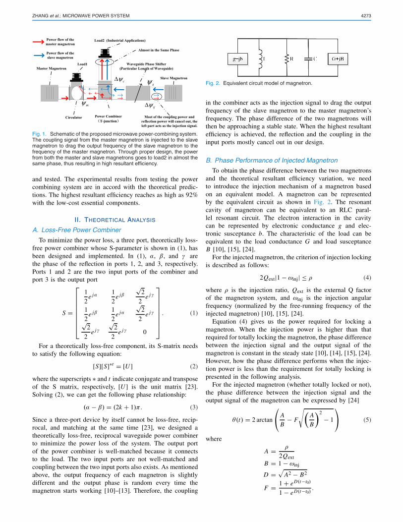
To obtain the phase difference between the two magnetronsand the theoretical resultant efficiency variation, we needto introduce the injection mechanism of a magnetron basedon an equivalent model. A magnetron can be representedby the equivalent circuit as shown in Fig. 2. The resonantcavity of magnetron can be equivalent to an RLC paral-lel resonant circuit. The electron interaction in the cavitycan be represented by electronic conductance g and elec-tronic susceptance b. The characteristic of the load can beequivalent to the load conductance G and load susceptanceB [10], [15], [24].
For the injected magnetron, the criterion of injection lockingis described as follows:
2Qext|1 − ωinj| ≤ ρ (4)
where ρ is the injection ratio, Qext is the external Q factorof the magnetron system, and ωinj is the injection angularfrequency (normalized by the free-running frequency of theinjected magnetron) [10], [15], [24].
Equation (4) gives us the power required for locking amagnetron. When the injection power is higher than thatrequired for totally locking the magnetron, the phase differencebetween the injection signal and the output signal of themagnetron is constant in the steady state [10], [14], [15], [24].However, how the phase difference performs when the injec-tion power is less than the requirement for totally locking ispresented in the following analysis.
For the injected magnetron (whether totally locked or not),the phase difference between the injection signal and theoutput signal of the magnetron can be expressed by [24]
θ(t) = 2 arctan
⎛⎝ A
B− F
√(A
B
)2
− 1
⎞⎠ (5)
where
A = ρ
2QextB = 1 − ωinj
D =√
A2 − B2
F = 1 + eD(t−t0)
1 − eD(t−t0).
4274 IEEE TRANSACTIONS ON ELECTRON DEVICES, VOL. 64, NO. 10, OCTOBER 2017
Fig. 3. Phase difference variation with injection ratio.
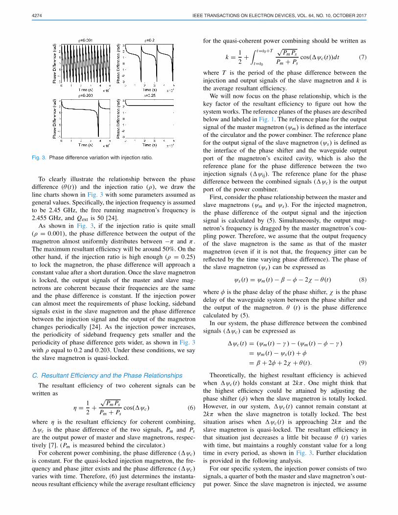
To clearly illustrate the relationship between the phasedifference (θ(t)) and the injection ratio (ρ), we draw theline charts shown in Fig. 3 with some parameters assumed asgeneral values. Specifically, the injection frequency is assumedto be 2.45 GHz, the free running magnetron’s frequency is2.455 GHz, and Qext is 50 [24].
As shown in Fig. 3, if the injection ratio is quite small(ρ = 0.001), the phase difference between the output of themagnetron almost uniformly distributes between −π and π .The maximum resultant efficiency will be around 50%. On theother hand, if the injection ratio is high enough (ρ = 0.25)to lock the magnetron, the phase difference will approach aconstant value after a short duration. Once the slave magnetronis locked, the output signals of the master and slave mag-netrons are coherent because their frequencies are the sameand the phase difference is constant. If the injection powercan almost meet the requirements of phase locking, sidebandsignals exist in the slave magnetron and the phase differencebetween the injection signal and the output of the magnetronchanges periodically [24]. As the injection power increases,the periodicity of sideband frequency gets smaller and theperiodicity of phase difference gets wider, as shown in Fig. 3with ρ equal to 0.2 and 0.203. Under these conditions, we saythe slave magnetron is quasi-locked.
C. Resultant Efficiency and the Phase Relationships
The resultant efficiency of two coherent signals can bewritten as
η = 1
2+
√Pm Ps
Pm + Pscos(ψc) (6)
where η is the resultant efficiency for coherent combining,ψc is the phase difference of the two signals, Pm and Ps
are the output power of master and slave magnetrons, respec-tively [7]. (Pm is measured behind the circulator.)
For coherent power combining, the phase difference (ψc)is constant. For the quasi-locked injection magnetron, the fre-quency and phase jitter exists and the phase difference (ψc)varies with time. Therefore, (6) just determines the instanta-neous resultant efficiency while the average resultant efficiency
for the quasi-coherent power combining should be written as
k = 1
2+
∫ t=t0+T
t=t0
√Pm Ps
Pm + Pscos(ψc(t))dt (7)
where T is the period of the phase difference between theinjection and output signals of the slave magnetron and k isthe average resultant efficiency.
We will now focus on the phase relationship, which is thekey factor of the resultant efficiency to figure out how thesystem works. The reference planes of the phases are describedbelow and labeled in Fig. 1. The reference plane for the outputsignal of the master magnetron (ψm) is defined as the interfaceof the circulator and the power combiner. The reference planefor the output signal of the slave magnetron (ψs) is defined asthe interface of the phase shifter and the waveguide outputport of the magnetron’s excited cavity, which is also thereference plane for the phase difference between the twoinjection signals (ψij). The reference plane for the phasedifference between the combined signals (ψc) is the outputport of the power combiner.
First, consider the phase relationship between the master andslave magnetrons (ψm and ψs). For the injected magnetron,the phase difference of the output signal and the injectionsignal is calculated by (5). Simultaneously, the output mag-netron’s frequency is dragged by the master magnetron’s cou-pling power. Therefore, we assume that the output frequencyof the slave magnetron is the same as that of the mastermagnetron (even if it is not that, the frequency jitter can bereflected by the time varying phase difference). The phase ofthe slave magnetron (ψs) can be expressed as
ψs(t) = ψm(t)− β − φ − 2χ − θ(t) (8)
where φ is the phase delay of the phase shifter, χ is the phasedelay of the waveguide system between the phase shifter andthe output of the magnetron. θ (t) is the phase differencecalculated by (5).
In our system, the phase difference between the combinedsignals (ψc) can be expressed as
ψc(t) = (ψm(t)− γ )− (ψm(t)− φ − γ )
= ψm(t)− ψs(t)+ φ
= β + 2φ + 2χ + θ(t). (9)
Theoretically, the highest resultant efficiency is achievedwhen ψc(t) holds constant at 2kπ . One might think thatthe highest efficiency could be attained by adjusting thephase shifter (φ) when the slave magnetron is totally locked.However, in our system, ψc(t) cannot remain constant at2kπ when the slave magnetron is totally locked. The bestsituation arises when ψc(t) is approaching 2kπ and theslave magnetron is quasi-locked. The resultant efficiency inthat situation just decreases a little bit because θ (t) varieswith time, but maintains a roughly constant value for a longtime in every period, as shown in Fig. 3. Further elucidationis provided in the following analysis.
For our specific system, the injection power consists of twosignals, a quarter of both the master and slave magnetron’s out-put power. Since the slave magnetron is injected, we assume
ZHANG et al.: MICROWAVE POWER SYSTEM 4275
that the frequency of the slave magnetron is the same as that ofthe master magnetron. Therefore, the phase difference betweenthe two injection signals can be expressed as
ψij(t) = (ψm(t)− β − φ)− (ψs(t)− φ − α − φ)
= ψc(t)+ (α − β). (10)
From (3), we concluded that (α − β) = (2k + 1)π . There-fore, when the highest resultant efficiency is obtained (ψc(t)is around 2kπ), the injection power is at a minimum (ψij(t)is around (2k + 1)π), and vice versa. This will explain theexperimental results in Section III that showed the highestresultant efficiency is always attained when the slave mag-netron is quasi-locked. In fact, the system approaches anequilibrium state under the lowest injection power becausethe phase difference is not constant (but remains roughlyconstant for a long time relative to the period). When theslave magnetron is just quasi-locked, the resultant efficiencyreaches its peak level in our specific system because the powerabsorbed by load1 connected with the circulator is the lowestunder this condition. Although the highest resultant efficiencywill be a little bit lower than that obtained in the coherentsituation, the tradeoff between the little decrease in resultantefficiency and the high reduction in the costs as well as systemsimplification is very effective.
III. RESULTS AND DISCUSSION
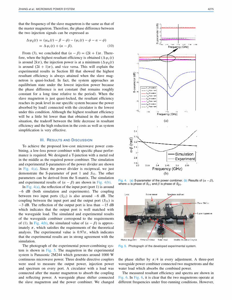
To achieve the proposed low-cost microwave power com-bining, a low-loss power combiner with specific phase perfor-mance is required. We designed a T-junction with a metal rodin the middle as the required power combiner. The simulationand experimental S-parameters of the power divider are shownin Fig. 4(a). Since the power divider is reciprocal, we justdemonstrate the S-parameter of port 1 and S33. The otherparameters can be derived from the S-matrix. The simulationand experimental results of (α − β) are shown in Fig. 4(b).
In Fig. 4(a), the reflection of the input port (port 1) is around−6 dB (both simulation and experiments). The couplingbetween two input ports (S21) is also around −6 dB. Thecoupling between the input port and the output port (S31) is−3 dB. The reflection of the output port is less than −15 dBwhich indicates that the output port is well matched withthe waveguide load. The simulated and experimental resultsof the waveguide combiner correspond to the requirementsof (1). In Fig. 4(b), the simulated value of (α − β) is approx-imately π , which satisfies the requirements of the theoreticalanalysis. The experimental value is 0.97π , which indicatesthat the experimental results are in strong agreement with thesimulation.
The photograph of the experimental power-combining sys-tem is shown in Fig. 5. The magnetron in the experimentalsystem is Panasonic 2M244 which generates around 1000 Wcontinuous microwave power. Three double directive couplerswere used to measure the output power, injection powerand spectrum on every port. A circulator with a load wasconnected after the master magnetron to absorb the couplingand reflecting power. A waveguide phase shifter connectedthe slave magnetron and the power combiner. We changed
Fig. 4. (a) S-parameter of the power combiner. (b) Results of (α − β),where α is phase of S11 and β is phase of S21.
Fig. 5. Photograph of the developed experimental system.
the phase shifter by π/4 in every adjustment. A three-portwaveguide power combiner connected two magnetrons and thewater load which absorbs the combined power.
The measured resultant efficiency and spectra are shown inFig. 6. In Fig. 6, it is clear that the two magnetrons operate atdifferent frequencies under free-running conditions. However,
4276 IEEE TRANSACTIONS ON ELECTRON DEVICES, VOL. 64, NO. 10, OCTOBER 2017
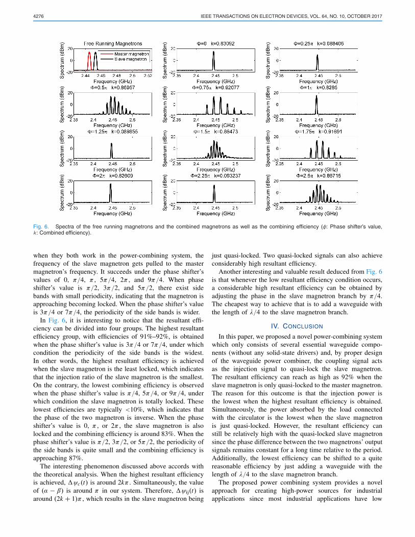
Fig. 6. Spectra of the free running magnetrons and the combined magnetrons as well as the combining efficiency (φ: Phase shifter’s value,k : Combined efficiency).
when they both work in the power-combining system, thefrequency of the slave magnetron gets pulled to the mastermagnetron’s frequency. It succeeds under the phase shifter’svalues of 0, π/4, π , 5π/4, 2π , and 9π/4. When phaseshifter’s value is π/2, 3π/2, and 5π/2, there exist sidebands with small periodicity, indicating that the magnetron isapproaching becoming locked. When the phase shifter’s valueis 3π/4 or 7π/4, the periodicity of the side bands is wider.
In Fig. 6, it is interesting to notice that the resultant effi-ciency can be divided into four groups. The highest resultantefficiency group, with efficiencies of 91%–92%, is obtainedwhen the phase shifter’s value is 3π/4 or 7π/4, under whichcondition the periodicity of the side bands is the widest.In other words, the highest resultant efficiency is achievedwhen the slave magnetron is the least locked, which indicatesthat the injection ratio of the slave magnetron is the smallest.On the contrary, the lowest combining efficiency is observedwhen the phase shifter’s value is π/4, 5π/4, or 9π/4, underwhich condition the slave magnetron is totally locked. Theselowest efficiencies are typically <10%, which indicates thatthe phase of the two magnetron is inverse. When the phaseshifter’s value is 0, π , or 2π , the slave magnetron is alsolocked and the combining efficiency is around 83%. When thephase shifter’s value is π/2, 3π/2, or 5π/2, the periodicity ofthe side bands is quite small and the combining efficiency isapproaching 87%.
The interesting phenomenon discussed above accords withthe theoretical analysis. When the highest resultant efficiencyis achieved, ψc(t) is around 2kπ . Simultaneously, the valueof (α − β) is around π in our system. Therefore, ψij(t) isaround (2k + 1)π , which results in the slave magnetron being
just quasi-locked. Two quasi-locked signals can also achieveconsiderably high resultant efficiency.
Another interesting and valuable result deduced from Fig. 6is that whenever the low resultant efficiency condition occurs,a considerable high resultant efficiency can be obtained byadjusting the phase in the slave magnetron branch by π/4.The cheapest way to achieve that is to add a waveguide withthe length of λ/4 to the slave magnetron branch.
IV. CONCLUSION
In this paper, we proposed a novel power-combining systemwhich only consists of several essential waveguide compo-nents (without any solid-state drivers) and, by proper designof the waveguide power combiner, the coupling signal actsas the injection signal to quasi-lock the slave magnetron.The resultant efficiency can reach as high as 92% when theslave magnetron is only quasi-locked to the master magnetron.The reason for this outcome is that the injection power isthe lowest when the highest resultant efficiency is obtained.Simultaneously, the power absorbed by the load connectedwith the circulator is the lowest when the slave magnetronis just quasi-locked. However, the resultant efficiency canstill be relatively high with the quasi-locked slave magnetronsince the phase difference between the two magnetrons’ outputsignals remains constant for a long time relative to the period.Additionally, the lowest efficiency can be shifted to a quitereasonable efficiency by just adding a waveguide with thelength of λ/4 to the slave magnetron branch.
The proposed power combining system provides a novelapproach for creating high-power sources for industrialapplications since most industrial applications have low

ZHANG et al.: MICROWAVE POWER SYSTEM 4277
requirements for frequency purity and high concerns regard-ing cost and longevity. For the applications which requirehigh signal quality, the system can also be considered sincethe resultant efficiency of the single frequency situation canalso reach 82%. Furthermore, the proposed power-combiningsystem shows a way to develop high power and low-costsystems with multiple sources. Every source can be injectedby the coupling between each other. The challenge for suchsystems is first deriving the S-parameter of the waveguidepower combiner (both magnitude and phase requirements), andthen designing the power combiner with specific structures.The power combining system will be capable of providinghigh microwave power output.
REFERENCES
[1] C. T. Searfass, C. Pheil, K. Sinding, B. R. Tittmann, A. Baba, andD. K. Agrawal, “Bismuth titanate fabricated by spray-on deposition andmicrowave sintering for high-temperature ultrasonic transducers,” IEEETrans. Ultrason., Ferroelect., Freq. Control, vol. 63, no. 1, pp. 139–146,Jan. 2016.
[2] P. J. Rathod, V. P. Anitha, G. V. Prakash, and Z. H. Sholapurwala,“A magnetron pulsed modulator for microwave plasma interactionstudies,” in Proc. IEEE Pulsed Power Conf. (PPC), May/Jun. 2015,pp. 1–4.
[3] V. P. Anitha, P. J. Rathod, R. Singh, and D. V. Giri, “Developmentalaspects of microwave–plasma interaction experiments: Phase-1,” IEEETrans. Plasma Sci., vol. 44, no. 10, pp. 2226–2231, Oct. 2016.
[4] Y. Pianroj, S. Jumrat, W. Werapun, S. Karrila, and C. Tongurai, “Scaled-up reactor for microwave induced pyrolysis of oil palm shell,” Chem.Eng. Process., Process Intensification, vol. 106, pp. 42–49, Aug. 2016.
[5] M. Vollmer, “Physics of the microwave oven,” Phys. Edu., vol. 39, no. 1,p. 74, 2004.
[6] S. K. Vyas, S. Maurya, and V. P. Singh, “Electromagnetic and particle-in-cell simulation studies of a high power strap and vane CW mag-netron,” IEEE Trans. Plasma Sci., vol. 42, no. 10, pp. 3373–3379,Oct. 2014.
[7] C. Liu, H. Huang, Z. Liu, F. Huo, and K. Huang, “Experimentalstudy on microwave power combining based on injection-locked 15-kWS-band continuous-wave magnetrons,” IEEE Trans. Plasma Sci., vol. 44,no. 8, pp. 1291–1297, Aug. 2016.
[8] S. Qi et al., “Secondary electron emission of the cathode in high-powercontinuous wave magnetron tubes,” in Proc. 10th Int. Vac. ElectronSources Conf. (IVESC), Jun./Jul. 2014, pp. 1–2.
[9] S. Qi et al., “Study on a novel Y2O3-Gd2O3-HfO2 impregnated W basedirect-heated cathode,” in Proc. IEEE Int. Vac. Electron. Conf. (IVEC),Apr. 2016, pp. 1–2.
[10] S. C. Chen, “Growth and frequency pushing effects in relativisticmagnetron phase-locking,” IEEE Trans. Plasma Sci., vol. 18, no. 3,pp. 570–576, Jun. 1990.
[11] A. S. Gimour, Klystrons, Traveling Wave Tubes, Magnetrons, Crossed-Field Amplifiers, and Gyrotrons. Beijing, China: National DefenceIndustry Press, 2011, pp. 334–378.
[12] Y. Zhang, P. Yuan, W. Ye, H. Zhu, Y. Yang, and K. Huang, “Frequencyqusai locking and noise reduction of the self-injection qusai lockedmagnetron,” Int. J. Appl. Electromagn. Mech., vol. 51, no. 1, pp. 71–81,2016.
[13] N. Shinohara, J. Fujiwara, and H. Matsumoto, “Development of activephased array with phase-controlled magnetrons,” in Proc. Int. Symp.Antennas Propag. Jpn., vol. 2. 2000, pp. 713–716.
[14] R. Adler, “A study of locking phenomena in oscillators,” Proc. IRE,vol. 34, no. 6, pp. 351–357, Jun. 1946.
[15] J. C. Slater, “The phasing of magnetrons,” Res. Lab. Electron.,Massachusetts Inst. Technol., Cambridge, MA, USA, Tech. Rep. 35,1947.
[16] I. Tahir, A. Dexter, and R. Carter, “Noise performance of frequency- andphase-locked CW magnetrons operated as current-controlled oscillators,”IEEE Trans. Electron Devices, vol. 52, no. 9, pp. 2096–2103, Sep. 2005.
[17] A. C. Dexter et al., “First demonstration and performance of an injectionlocked continuous wave magnetron to phase control a superconductingcavity,” Phys. Rev. ST Accel. Beams., vol. 14, no. 3, p. 032001, 2011.
[18] W. C. Brown, “The magnetron—A low noise, long life amplifier,” Appl.Microw., pp. 117–121, Summer 1990.
[19] G. Kazakevich et al., “High-power magnetron transmitter asan RF source for superconducting linear accelerators,” Nucl. Instrum.Methods Phys. Res. A, Accel., Spectrom., Detect. Assoc. Equip., vol. 760,pp. 19–27, Oct. 2014.
[20] S. Yue, Z.-C. Zhang, and D.-P. Gao, “Analysis of the injection-lockedmagnetron with a mismatched circulator,” Chin. Phys. B, vol. 23, no. 8,p. 088402, 2014.
[21] N. Shinohara and H. Matsumoto, “Research on magnetron phased arraywith mutual injection locking for space solar power satellite/station,”Elect. Eng. Jpn., vol. 173, no. 2, pp. 21–32, Nov. 2010.
[22] P. Yuan, Y. Zhang, W. Ye, H. Zhu, K. Huang, and Y. Yang, “Power-combining based on master–slave injection-locking magnetron,” Chin.Phys. B, vol. 25, no. 7, p. 078402, 2016.
[23] D. M. Pozar, Microwave Engineering, 3rd ed. Hoboken, NJ, USA: Wiley,2005, pp. 317–380.
[24] P. Pengvanich et al., “Modeling and experimental studies of magnetroninjection locking,” J. Appl. Phys., vol. 98, no. 11, p. 114903, 2005.
Yi Zhang received the B.Sc. degree in electricengineering and information from Sichuan Uni-versity, Chengdu, China, in 2013, where he hasbeen pursuing the Ph.D. degree.
He is a Visiting Fellow with Material ResearchInstitute, Pennsylvania State University, StateCollege, PA, USA, which is supported byChina Scholarship Council. His current researchinterests include microwave power combining,microwave sources, and microwave processingand application.
Kama Huang (M’01–A’01–SM’04) received theM.S. and Ph.D. degrees in microwave theoryand technology from the University of Elec-tronic Science and Technology, Chengdu, China,in 1988 and 1991, respectively.
He has been a Professor with the Departmentof Radio and Electronics of Sichuan University,Sichuan, China, since 1994, and has been theDirector of the department since 1997. He hasauthored or co-authored over 100 papers.
Dinesh K. Agrawal received the master’sdegree in physics from Banaras Hindu Univer-sity, Varanasi, India, and the master’s degree inmaterials Science from IIT, Kanpur, India, andthe Ph.D. degree from the Pennsylvania StateUniversity, State College, PA, USA, in 1979.
Since 1997, he has been a Senior Scientist,and the Director of Microwave Processing andEngineering Center, The Pennsylvania State Uni-versity, State College, PA, USA.
Tania Slawecki received the B.A. degreein astronomy/physics from Lycoming College,Williamsport, PA, USA, in 1987, the M.S. degreein physics and the Ph.D. degree in materialsscience and engineering from Penn State Univer-sity, State College, PA, USA, in 1989 and 1995,respectively.
Since 2004, she has been a Research Asso-ciate with the Materials Research Institute, PennState University, State College, PA, USA.

4278 IEEE TRANSACTIONS ON ELECTRON DEVICES, VOL. 64, NO. 10, OCTOBER 2017
Huacheng Zhu received the B.S. degree in elec-tric engineering and the Ph.D. degree in informa-tion and radio physics from Sichuan University,Chengdu, China, in 2009 and 2014, respectively.
From 2012 to 2013, he was a Visiting Fellowwith the Department of Biological and Environ-mental Engineering, Cornell University, Ithaca,NY, USA, which was supported by China Schol-arship Council. Since 2015, he has been aFaculty Member of Sichuan University.
Yang Yang received the Ph.D. degree inradio physics from Sichuan University, Chengdu,China, in 2010.
From 2008 to 2010, he was a Visiting Fellowwith Clemson University, where he was a VisitingScholar with the Oak Ridge National Laboratory,Oak Ridge, TN, USA, in 2010. He is currentlyan Associate Professor with the College of Elec-tronics and Information Engineering, SichuanUniversity. His current research interests includemicrowave chemistry and the applications ofmicrowave energy.