Embed Size (px)
Citation preview
UUSSEERR‟‟SS MMAANNUUAALL VV11..00 220011440088
- 1 -
MID-RISE
SCISSOR LIFT
INSTRUCTION & MAINTENANCE
MANUAL
CL-S30Z
Lifting capacity:3000kg
Read this entire manual carefully and completely
before installation or operation of the lift
UUSSEERR‟‟SS MMAANNUUAALL VV11..00 220011440088
- 2 -
SCISSOR LIFT INSTRUCTION MANUAL
INDEX PAGE
1.Packing, transport and storage .......................................................................................................................... - 3 -
1.1.Packing: ................................................................................................................................................. - 3 -
1.2.Transport: ............................................................................................................................................... - 4 -
1.3.Storage ................................................................................................................................................... - 4 -
2.Manual introduction ........................................................................................................................................... - 4 -
3.Description of the machine ................................................................................................................................ - 5 -
3.1.Machine Application ............................................................................................................................... - 5 -
3.2.Structure Features .................................................................................................................................. - 5 -
3.3.Equipment .............................................................................................................................................. - 6 -
3.4.Frame ..................................................................................................................................................... - 6 -
3.5.Control box ............................................................................................................................................. - 6 -
4. Specifications .................................................................................................................................................... - 6 -
4.1.Main technical parameter ....................................................................................................................... - 7 -
4.2.External dimension drawing ................................................................................................................... - 8 -
4.3.Types of vehicles suitable for ................................................................................................................. - 9 -
5. Safety notes .................................................................................................................................................... - 10 -
6. Installation ...................................................................................................................................................... - 13 -
7. Adjustment ...................................................................................................................................................... - 18 -
8. Operation ........................................................................................................................................................ - 20 -
9. Maintenance and care .................................................................................................................................... - 22 -
10.Trouble shooting table ................................................................................................................................... - 23 -
11.Hydraulic pressure elements diagram ............................................................................................................ - 24 -
12.Hose connection diagram .............................................................................................................................. - 25 -
13.Circuit diagram .............................................................................................................................................. - 26 -
14.Gas loop diagram .......................................................................................................................................... - 28 -
15.Explosion drawing ......................................................................................................................................... - 29 -
16.Accessories packing list ................................................................................................................................. - 29 -
UUSSEERR‟‟SS MMAANNUUAALL VV11..00 220011440088
- 3 -
1. Packing, transport and storage
All packing, lifting, handling, transport and unpacking operations are to be performed exclusively
by expert personnel.
1.1. Packing:
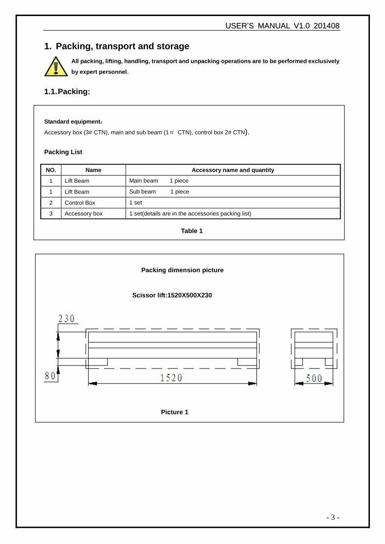
Standard equipment:
Accessory box (3# CTN), main and sub beam (1# CTN), control box 2# CTN).
Packing List
Table 1
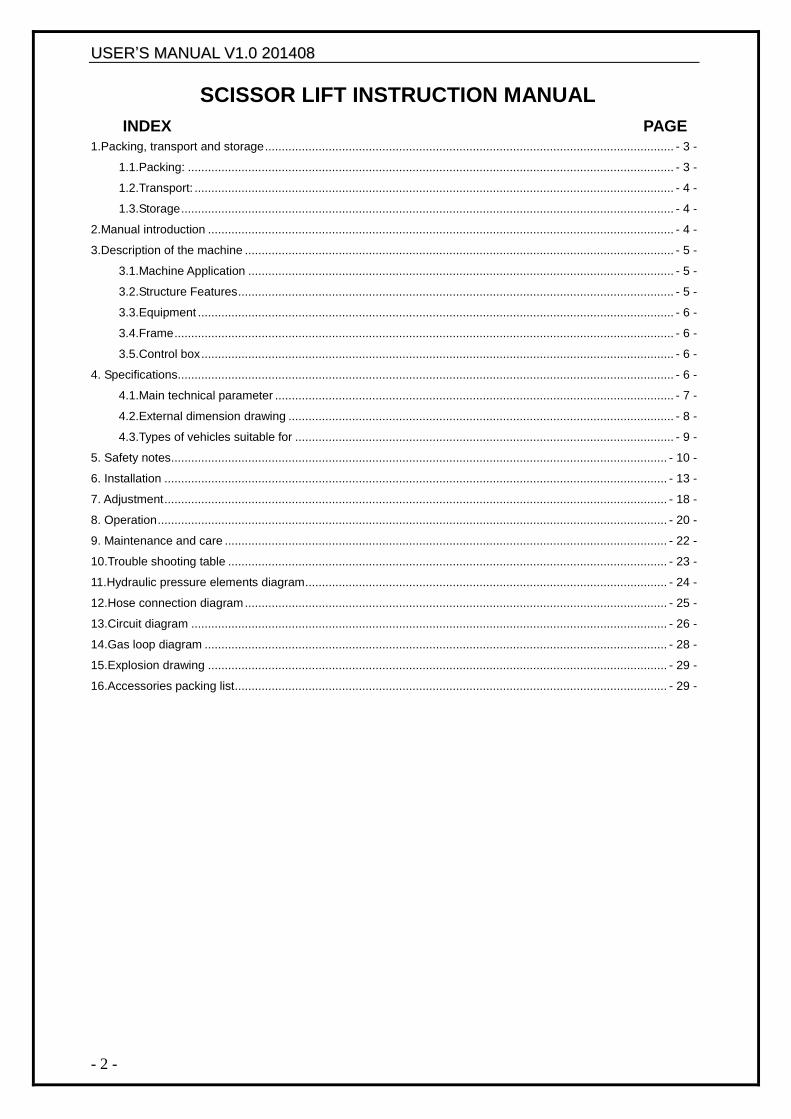
Packing dimension picture
NO. Name Accessory name and quantity
1 Lift Beam Main beam 1 piece
1 Lift Beam Sub beam 1 piece
2 Control Box 1 set
3 Accessory box 1 set(details are in the accessories packing list)
Scissor lift:1520X500X230
Picture 1
UUSSEERR‟‟SS MMAANNUUAALL VV11..00 220011440088
- 4 -
1.2. Transport:
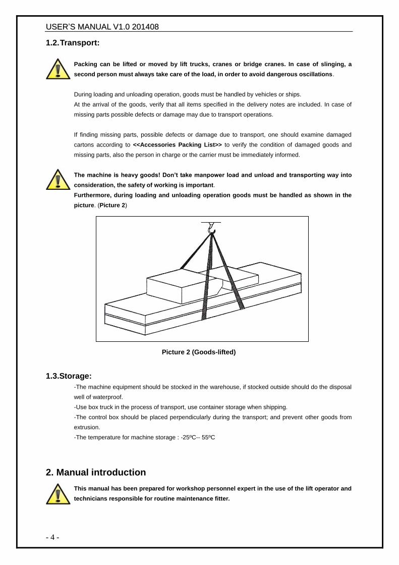
Packing can be lifted or moved by lift trucks, cranes or bridge cranes. In case of slinging, a
second person must always take care of the load, in order to avoid dangerous oscillations.
During loading and unloading operation, goods must be handled by vehicles or ships.
At the arrival of the goods, verify that all items specified in the delivery notes are included. In case of
missing parts possible defects or damage may due to transport operations.
If finding missing parts, possible defects or damage due to transport, one should examine damaged
cartons according to <<Accessories Packing List>> to verify the condition of damaged goods and
missing parts, also the person in charge or the carrier must be immediately informed.
The machine is heavy goods! Don’t take manpower load and unload and transporting way into
consideration, the safety of working is important.
Furthermore, during loading and unloading operation goods must be handled as shown in the
picture. (Picture 2)
Picture 2 (Goods-lifted)
1.3.Storage:
-The machine equipment should be stocked in the warehouse, if stocked outside should do the disposal
well of waterproof.
-Use box truck in the process of transport, use container storage when shipping.
-The control box should be placed perpendicularly during the transport; and prevent other goods from
extrusion.
-The temperature for machine storage : -25ºC-- 55ºC
2. Manual introduction
This manual has been prepared for workshop personnel expert in the use of the lift operator and
technicians responsible for routine maintenance fitter.
UUSSEERR‟‟SS MMAANNUUAALL VV11..00 220011440088
- 5 -
Workers should read the <<Instruction & Maintenance Manual>> carefully before carrying out any
operation with the lift. This manual contains important information regarding:
-The personal safety of operators and maintenance workers.
-Lift safety.
-The safety of lifted vehicles.
Several tips should be done by the operator as follow:
1.Well conserving the manual. Manufacturer owns the right to make little change for the manual owing to
the improvement of technology.
2.Good disposal the used oil.
3.The machine must be demolished by authorized technicians, just like for assembling
3. Description of the machine
3.1. Machine Application
Mid-rise scissor lift can lift each kind of vehicle whose weight is less than 3000kg, suitable for use in
vehicle tests, maintenance and caring for automobiles, which is particularly suitable for use in the
basement or on the floor, without construction and hole.
Lifts are designed and built to lift vehicles and hold them in the elevated position in an enclosed
workshop. All other uses of the lifts are unauthorized. In particular, the lifts are not suitable for:
-Washing spray work;
-Use in outdoors;
-Creating raised platforms for personnel or lifting personnel;
-Use as a press for crushing purposes;
-Use as elevator;
-Use as a lift jack for lifting vehicle bodies or changing wheels.
The manufacturer is not liable for any injury to persons or damage to vehicles and other property caused
by the incorrect and unauthorized use of the lifts.
3.2. Structure Features -Use hidden and thin scissor structure, dispense with construction and ground hole, the occupation is
small
-Independent control box, low-voltage controlling, good security
-Same hydraulic cubage and in-phase cylinder, the synchronization of platform
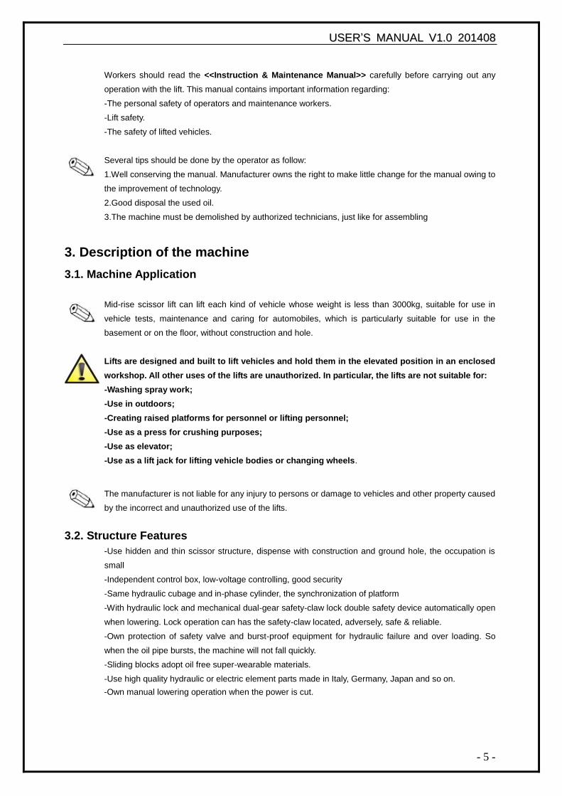
-With hydraulic lock and mechanical dual-gear safety-claw lock double safety device automatically open
when lowering. Lock operation can has the safety-claw located, adversely, safe & reliable.
-Own protection of safety valve and burst-proof equipment for hydraulic failure and over loading. So
when the oil pipe bursts, the machine will not fall quickly.
-Sliding blocks adopt oil free super-wearable materials.
-Use high quality hydraulic or electric element parts made in Italy, Germany, Japan and so on.
-Own manual lowering operation when the power is cut.
UUSSEERR‟‟SS MMAANNUUAALL VV11..00 220011440088
- 6 -
Safety lock structure
3.3. Equipment
-Machine basement (The position and space of equipment installation)
-Machine frame (The main structure of lift and insurance institution)
-Control box (Machine-controlled part)
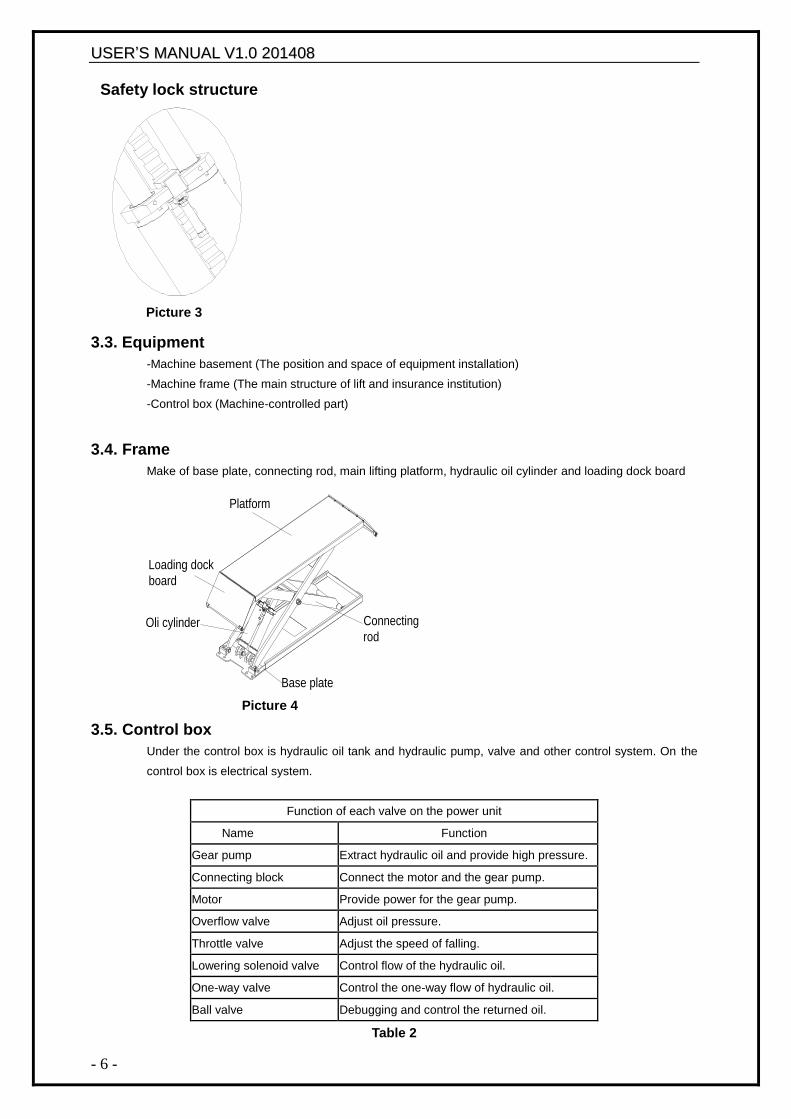
3.4. Frame
Make of base plate, connecting rod, main lifting platform, hydraulic oil cylinder and loading dock board
3.5. Control box Under the control box is hydraulic oil tank and hydraulic pump, valve and other control system. On the
control box is electrical system.
Function of each valve on the power unit
Name Function
Gear pump Extract hydraulic oil and provide high pressure.
Connecting block Connect the motor and the gear pump.
Motor Provide power for the gear pump.
Overflow valve Adjust oil pressure.
Throttle valve Adjust the speed of falling.
Lowering solenoid valve Control flow of the hydraulic oil.
One-way valve Control the one-way flow of hydraulic oil.
Ball valve Debugging and control the returned oil.
Table 2
Picture 3
Picture 4
Platform
Loading dock
board
Oli cylinder Connecting
rod
Base plate
UUSSEERR‟‟SS MMAANNUUAALL VV11..00 220011440088
- 7 -
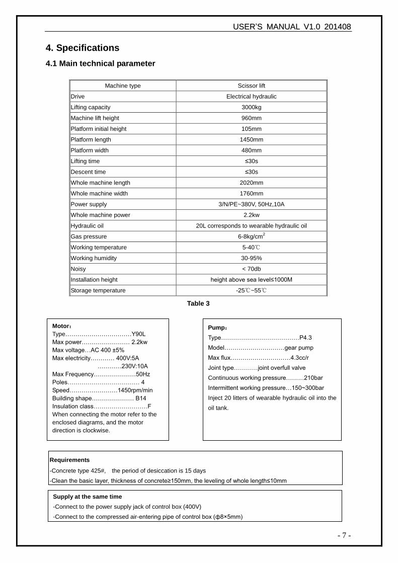
Motor:
Type……………………………Y90L
Max power…………………… 2.2kw
Max voltage…AC 400 ±5%
Max electricity………… 400V:5A
…………230V:10A
Max Frequency…………………50Hz
Poles……………………………… 4
Speed……………………1450rpm/min
Building shape………………… B14
Insulation class………………………F
When connecting the motor refer to the
enclosed diagrams, and the motor
direction is clockwise.
4. Specifications
4.1 Main technical parameter
Table 3
Machine type Scissor lift
Drive Electrical hydraulic
Lifting capacity 3000kg
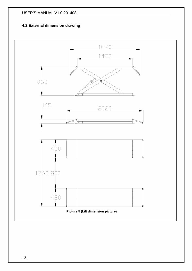
Machine lift height 960mm
Platform initial height 105mm
Platform length 1450mm
Platform width 480mm
Lifting time ≤30s
Descent time ≤30s
Whole machine length 2020mm
Whole machine width 1760mm
Power supply 3/N/PE~380V, 50Hz,10A
Whole machine power 2.2kw
Hydraulic oil 20L corresponds to wearable hydraulic oil
Gas pressure 6-8kg/cm2
Working temperature 5-40℃
Working humidity 30-95%
Noisy < 70db
Installation height height above sea level≤1000M
Storage temperature -25℃~55℃
Requirements
-Concrete type 425#, the period of desiccation is 15 days
-Clean the basic layer, thickness of concrete≥150mm, the leveling of whole length≤10mm
Pump:
Type…………………………………P4.3
Model…………………………gear pump
Max flux…………………………4.3cc/r
Joint type…………joint overfull valve
Continuous working pressure………210bar
Intermittent working pressure…150~300bar
Inject 20 litters of wearable hydraulic oil into the
oil tank.
Supply at the same time
-Connect to the power supply jack of control box (400V)
-Connect to the compressed air-entering pipe of control box (ф8×5mm)
UUSSEERR‟‟SS MMAANNUUAALL VV11..00 220011440088
- 8 -
4.2 External dimension drawing
Picture 5 (Lift dimension picture)
UUSSEERR‟‟SS MMAANNUUAALL VV11..00 220011440088
- 9 -
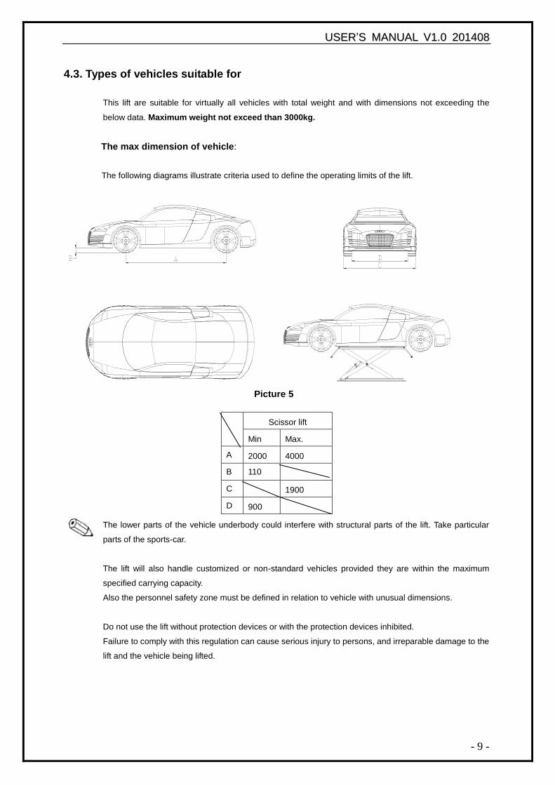
4.3. Types of vehicles suitable for
This lift are suitable for virtually all vehicles with total weight and with dimensions not exceeding the
below data. Maximum weight not exceed than 3000kg.
The max dimension of vehicle:
The following diagrams illustrate criteria used to define the operating limits of the lift.
Picture 5
The lower parts of the vehicle underbody could interfere with structural parts of the lift. Take particular
parts of the sports-car.
The lift will also handle customized or non-standard vehicles provided they are within the maximum
specified carrying capacity.
Also the personnel safety zone must be defined in relation to vehicle with unusual dimensions.
Do not use the lift without protection devices or with the protection devices inhibited.
Failure to comply with this regulation can cause serious injury to persons, and irreparable damage to the
lift and the vehicle being lifted.
Scissor lift
Min Max.
A 2000 4000
B 110
C 1900
D 900
UUSSEERR‟‟SS MMAANNUUAALL VV11..00 220011440088
- 10 -
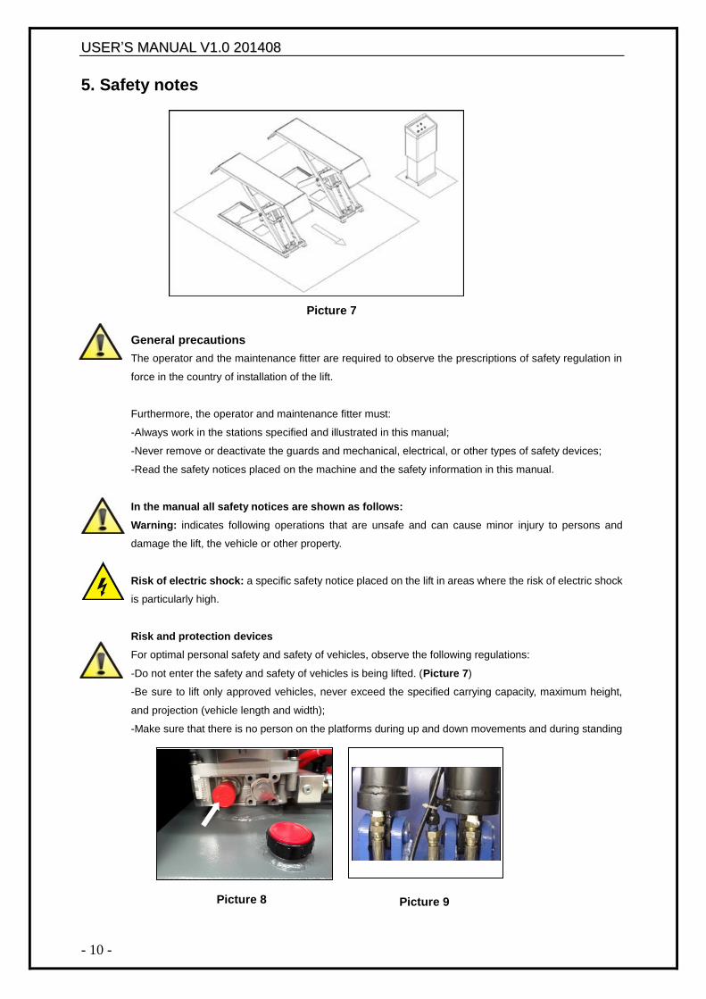
5. Safety notes
General precautions
The operator and the maintenance fitter are required to observe the prescriptions of safety regulation in
force in the country of installation of the lift.
Furthermore, the operator and maintenance fitter must:
-Always work in the stations specified and illustrated in this manual;
-Never remove or deactivate the guards and mechanical, electrical, or other types of safety devices;
-Read the safety notices placed on the machine and the safety information in this manual.
In the manual all safety notices are shown as follows:
Warning: indicates following operations that are unsafe and can cause minor injury to persons and
damage the lift, the vehicle or other property.
Risk of electric shock: a specific safety notice placed on the lift in areas where the risk of electric shock
is particularly high.
Risk and protection devices
For optimal personal safety and safety of vehicles, observe the following regulations:
-Do not enter the safety and safety of vehicles is being lifted. (Picture 7)
-Be sure to lift only approved vehicles, never exceed the specified carrying capacity, maximum height,
and projection (vehicle length and width);
-Make sure that there is no person on the platforms during up and down movements and during standing
Picture 8 Picture 9
Picture 7
UUSSEERR‟‟SS MMAANNUUAALL VV11..00 220011440088
- 11 -
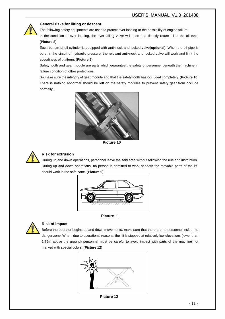
General risks for lifting or descent
The following safety equipments are used to protect over loading or the possibility of engine failure.
In the condition of over loading, the over-falling valve will open and directly return oil to the oil tank.
(Picture 8)
Each bottom of oil cylinder is equipped with antiknock and locked valve(optional). When the oil pipe is
burst in the circuit of hydraulic pressure, the relevant antiknock and locked valve will work and limit the
speediness of platform. (Picture 9)
Safety tooth and gear module are parts which guarantee the safety of personnel beneath the machine in
failure condition of other protections.
So make sure the integrity of gear module and that the safety tooth has occluded completely. (Picture 10)
There is nothing abnormal should be left on the safety modules to prevent safety gear from occlude
normally.
Picture 10
Risk for extrusion
During up and down operations, personnel leave the said area without following the rule and instruction.
During up and down operations, no person is admitted to work beneath the movable parts of the lift,
should work in the safe zone. (Picture 9)
Risk of impact
Before the operator begins up and down movements, make sure that there are no personnel inside the
danger zone. When, due to operational reasons, the lift is stopped at relatively low elevations (lower than
1.75m above the ground) personnel must be careful to avoid impact with parts of the machine not
marked with special colors. (Picture 12)
Picture 11
Picture 12
UUSSEERR‟‟SS MMAANNUUAALL VV11..00 220011440088
- 12 -
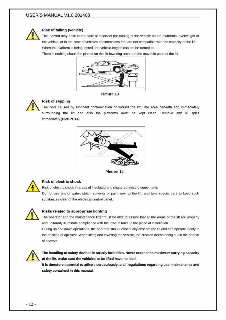
Risk of falling (vehicle)
This hazard may arise in the case of incorrect positioning of the vehicle on the platforms, overweight of
the vehicle, or in the case of vehicles of dimensions that are not compatible with the capacity of the lift.
When the platform is being tested, the vehicle engine can not be turned on.
There is nothing should be placed on the lift-lowering area and the movable parts of the lift.
Risk of slipping
The floor caused by lubricant contamination of around the lift. The area beneath and immediately
surrounding the lift and also the platforms must be kept clean. Remove any oil spills
immediately.(Picture 14)
Picture 14
Risk of electric shock
Risk of electric shock in areas of insulated and shattered electric equipments
Do not use jets of water, steam solvents or paint next to the lift, and take special care to keep such
substances clear of the electrical control panel.
Risks related to appropriate lighting
The operator and the maintenance fitter must be able to assure that all the areas of the lift are properly
and uniformly illuminate compliance with the laws in force in the place of installation.
During up and down operations, the operator should continually observe the lift and can operate it only in
the position of operator. When lifting and lowering the vehicle, the cushion needs being put in the bottom
of chassis.
The handling of safety devices is strictly forbidden. Never exceed the maximum carrying capacity
of the lift, make sure the vehicles to be lifted have no load.
It is therefore essential to adhere scrupulously to all regulations regarding use, maintenance and
safety contained in this manual.
Picture 13
UUSSEERR‟‟SS MMAANNUUAALL VV11..00 220011440088
- 13 -
6. Installation
Skilled and authorized personnel only should be allowed to perform these operations, follow all
instructions shown below carefully, in order to prevent possible damage to the car lift or risk of
injury to people.
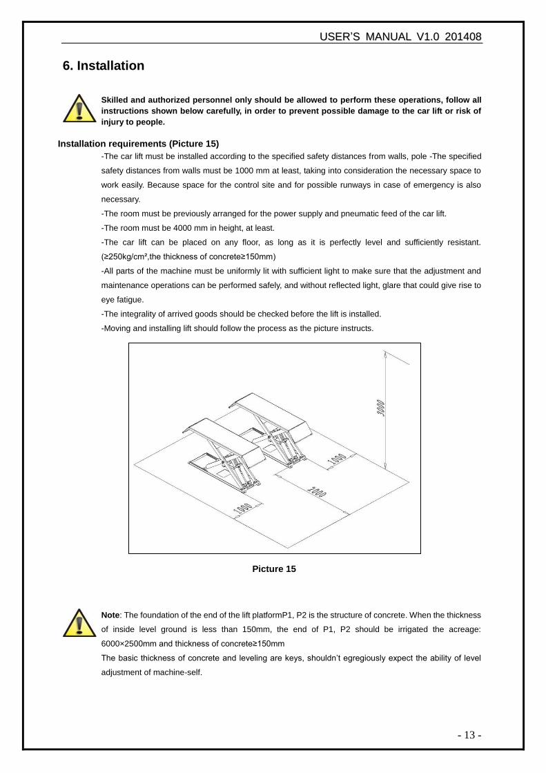
Installation requirements (Picture 15)
-The car lift must be installed according to the specified safety distances from walls, pole -The specified
safety distances from walls must be 1000 mm at least, taking into consideration the necessary space to
work easily. Because space for the control site and for possible runways in case of emergency is also
necessary.
-The room must be previously arranged for the power supply and pneumatic feed of the car lift.
-The room must be 4000 mm in height, at least.
-The car lift can be placed on any floor, as long as it is perfectly level and sufficiently resistant.
(≥250kg/cm²,the thickness of concrete≥150mm)
-All parts of the machine must be uniformly lit with sufficient light to make sure that the adjustment and
maintenance operations can be performed safely, and without reflected light, glare that could give rise to
eye fatigue.
-The integrality of arrived goods should be checked before the lift is installed.
-Moving and installing lift should follow the process as the picture instructs.
Note: The foundation of the end of the lift platformP1, P2 is the structure of concrete. When the thickness
of inside level ground is less than 150mm, the end of P1, P2 should be irrigated the acreage:
6000×2500mm and thickness of concrete≥150mm
The basic thickness of concrete and leveling are keys, shouldn‟t egregiously expect the ability of level
adjustment of machine-self.
Picture 15
UUSSEERR‟‟SS MMAANNUUAALL VV11..00 220011440088
- 14 -
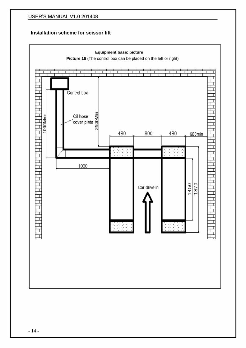
Installation scheme for scissor lift
Equipment basic picture
Picture 16 (The control box can be placed on the left or right)
UUSSEERR‟‟SS MMAANNUUAALL VV11..00 220011440088
- 15 -
Platform Installation:
-Place two lift platforms on the position of the location
-The bottom of oil cylinder is located in the frontage of machine (the direction of getting on the vehicle)
-Use fork car or other lifting equipments to lift the platform (Picture17) and make sure that the safety
equipment of machine is both turned on and locked.
Picture 17
To avoid failure of machine safety equipment, can insert a wood in the middle part of joint-pole.
Prohibit working beneath the lift when hydraulic system is not completely equipped with
hydraulic oil and take the action of up and down operations.
-When moving the lift platform, adjust the space between two platforms; make sure that the two
platforms are parallel.
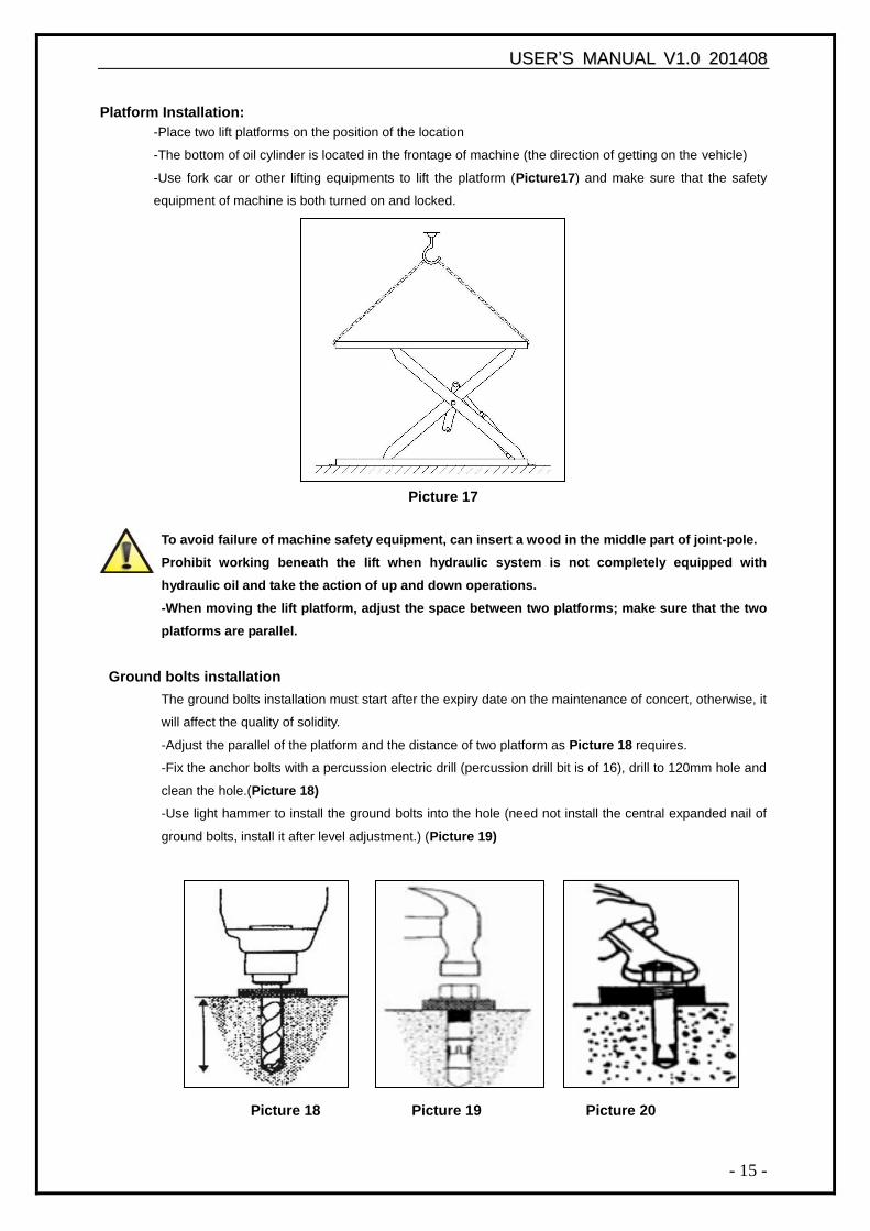
Ground bolts installation
The ground bolts installation must start after the expiry date on the maintenance of concert, otherwise, it
will affect the quality of solidity.
-Adjust the parallel of the platform and the distance of two platform as Picture 18 requires.
-Fix the anchor bolts with a percussion electric drill (percussion drill bit is of 16), drill to 120mm hole and
clean the hole.(Picture 18)
-Use light hammer to install the ground bolts into the hole (need not install the central expanded nail of
ground bolts, install it after level adjustment.) (Picture 19)
Picture 18 Picture 19 Picture 20
UUSSEERR‟‟SS MMAANNUUAALL VV11..00 220011440088
- 16 -
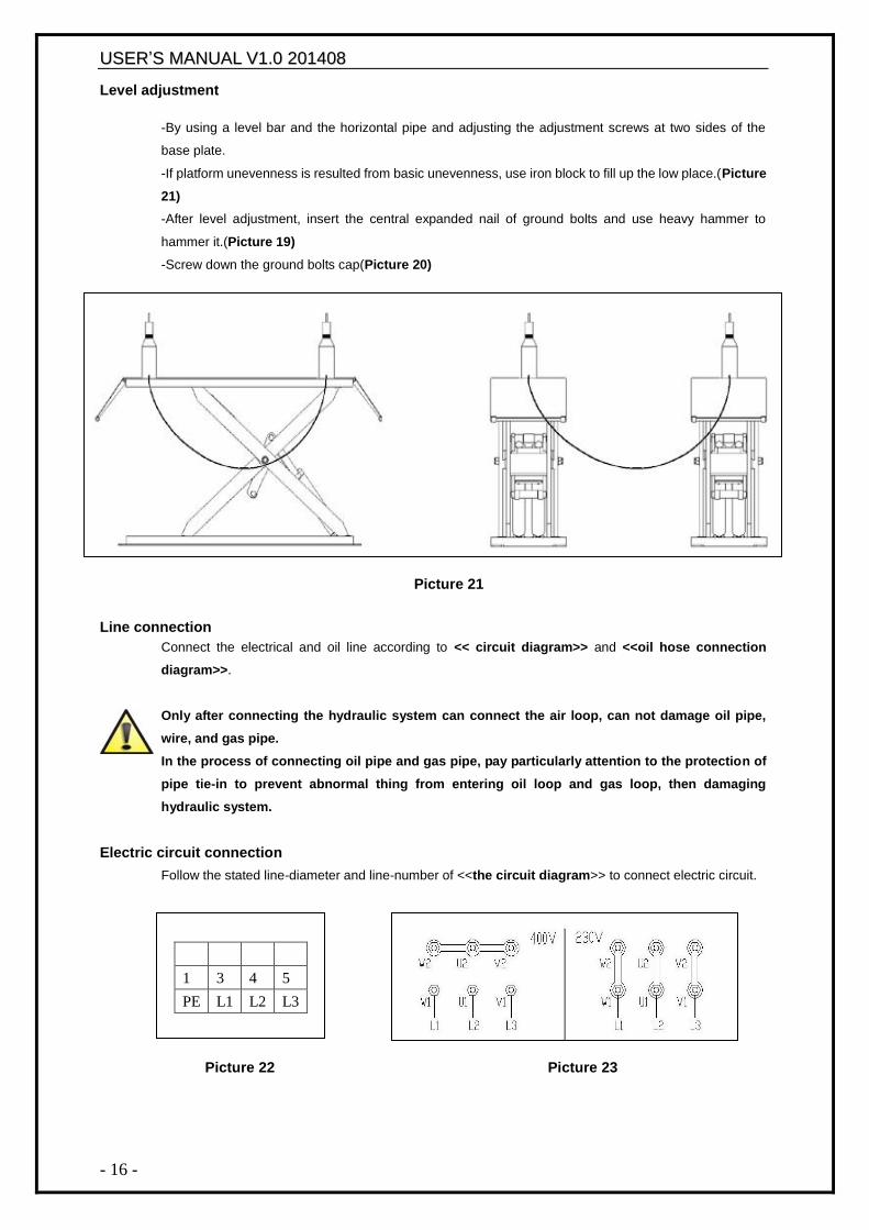
Level adjustment
-By using a level bar and the horizontal pipe and adjusting the adjustment screws at two sides of the
base plate.
-If platform unevenness is resulted from basic unevenness, use iron block to fill up the low place.(Picture
21)
-After level adjustment, insert the central expanded nail of ground bolts and use heavy hammer to
hammer it.(Picture 19)
-Screw down the ground bolts cap(Picture 20)
Picture 21
Line connection
Connect the electrical and oil line according to << circuit diagram>> and <<oil hose connection
diagram>>.
Only after connecting the hydraulic system can connect the air loop, can not damage oil pipe,
wire, and gas pipe.
In the process of connecting oil pipe and gas pipe, pay particularly attention to the protection of
pipe tie-in to prevent abnormal thing from entering oil loop and gas loop, then damaging
hydraulic system.
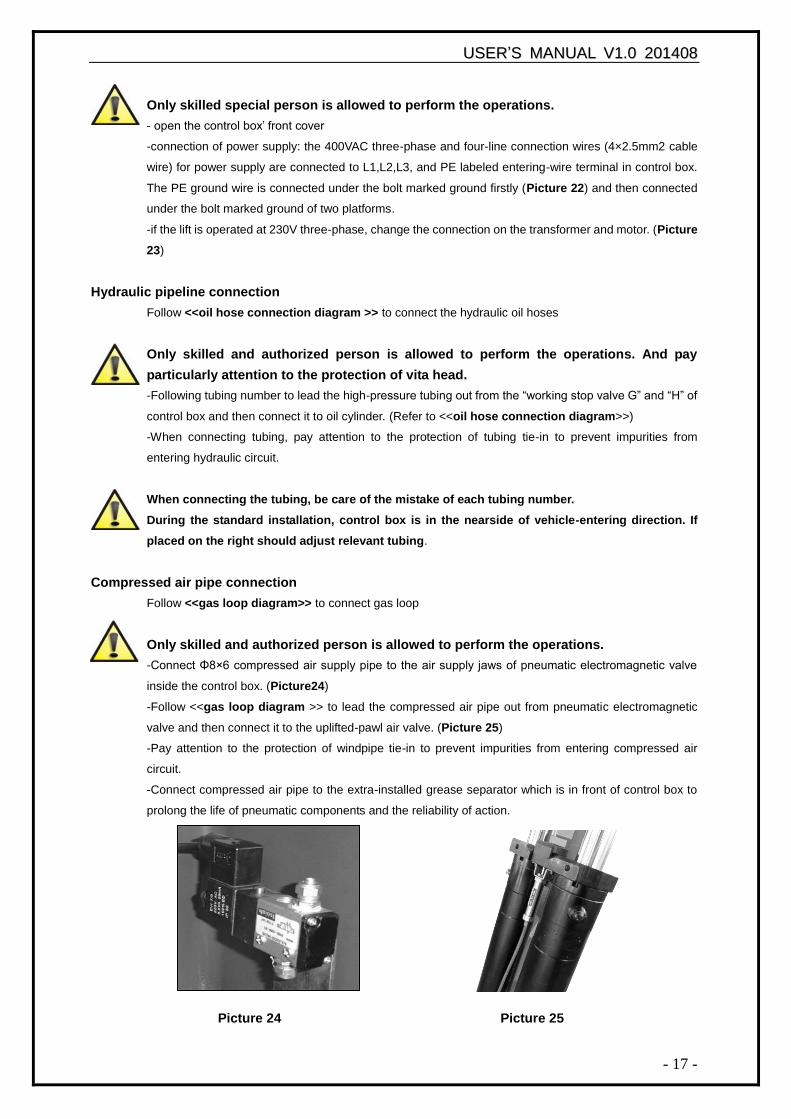
Electric circuit connection
Follow the stated line-diameter and line-number of <<the circuit diagram>> to connect electric circuit.
Picture 22 Picture 23
1 3 4 5
PE L1 L2 L3
UUSSEERR‟‟SS MMAANNUUAALL VV11..00 220011440088
- 17 -
Only skilled special person is allowed to perform the operations.
- open the control box‟ front cover
-connection of power supply: the 400VAC three-phase and four-line connection wires (4×2.5mm2 cable
wire) for power supply are connected to L1,L2,L3, and PE labeled entering-wire terminal in control box.
The PE ground wire is connected under the bolt marked ground firstly (Picture 22) and then connected
under the bolt marked ground of two platforms.
-if the lift is operated at 230V three-phase, change the connection on the transformer and motor. (Picture
23)
Hydraulic pipeline connection
Follow <<oil hose connection diagram >> to connect the hydraulic oil hoses
Only skilled and authorized person is allowed to perform the operations. And pay
particularly attention to the protection of vita head.
-Following tubing number to lead the high-pressure tubing out from the “working stop valve G” and “H” of
control box and then connect it to oil cylinder. (Refer to <<oil hose connection diagram>>)
-When connecting tubing, pay attention to the protection of tubing tie-in to prevent impurities from
entering hydraulic circuit.
When connecting the tubing, be care of the mistake of each tubing number.
During the standard installation, control box is in the nearside of vehicle-entering direction. If
placed on the right should adjust relevant tubing.
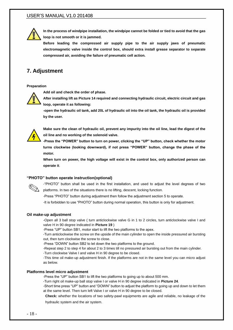
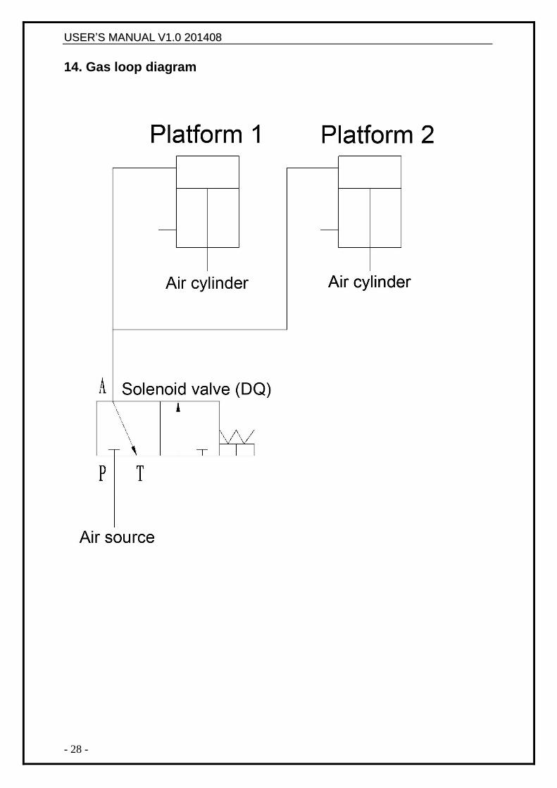
Compressed air pipe connection
Follow <<gas loop diagram>> to connect gas loop
Only skilled and authorized person is allowed to perform the operations.
-Connect Φ8×6 compressed air supply pipe to the air supply jaws of pneumatic electromagnetic valve
inside the control box. (Picture24)
-Follow <<gas loop diagram >> to lead the compressed air pipe out from pneumatic electromagnetic
valve and then connect it to the uplifted-pawl air valve. (Picture 25)
-Pay attention to the protection of windpipe tie-in to prevent impurities from entering compressed air
circuit.
-Connect compressed air pipe to the extra-installed grease separator which is in front of control box to
prolong the life of pneumatic components and the reliability of action.
Picture 24 Picture 25
UUSSEERR‟‟SS MMAANNUUAALL VV11..00 220011440088
- 18 -
In the process of windpipe installation, the windpipe cannot be folded or tied to avoid that the gas
loop is not smooth or it is jammed.
Before leading the compressed air supply pipe to the air supply jaws of pneumatic
electromagnetic valve inside the control box, should extra install grease separator to separate
compressed air, avoiding the failure of pneumatic cell action.
7. Adjustment
Preparation
Add oil and check the order of phase.
After installing lift as Picture 14 required and connecting hydraulic circuit, electric circuit and gas
loop, operate it as following:
-open the hydraulic oil tank, add 20L of hydraulic oil into the oil tank, the hydraulic oil is provided
by the user.
Make sure the clean of hydraulic oil, prevent any impurity into the oil line, lead the digest of the
oil line and no working of the solenoid valve.
-Press the “POWER” button to turn on power, clicking the “UP” button, check whether the motor
turns clockwise (looking downward), if not press “POWER” button, change the phase of the
motor.
When turn on power, the high voltage will exist in the control box, only authorized person can
operate it.
“PHOTO” button operate instruction(optional)
-“PHOTO” button shall be used in the first installation, and used to adjust the level degrees of two
platforms. In two of the situations there is no lifting, descent, locking function.
-Press “PHOTO” button during adjustment then follow the adjustment section 5 to operate.
-It is forbidden to use “PHOTO” button during normal operation, this button is only for adjustment.
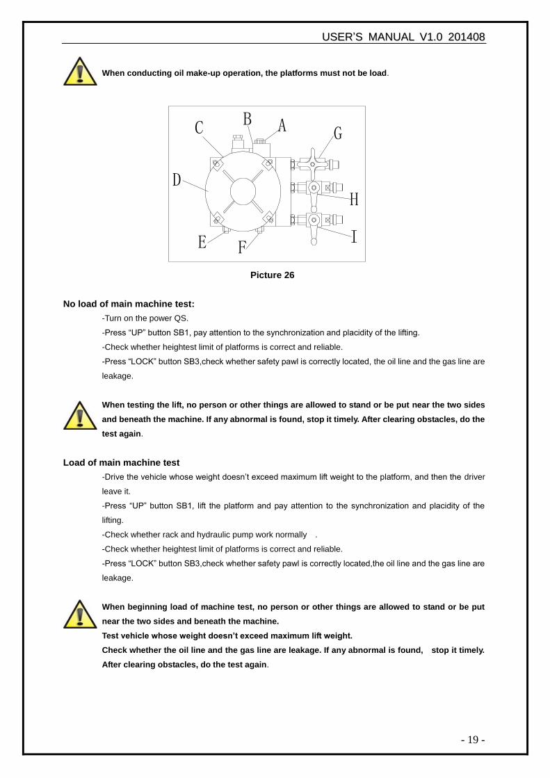
Oil make-up adjustment
-Open all 3 ball stop valve ( turn anticlockwise valve G in 1 to 2 circles, turn anticlockwise valve I and
valve H in 90 degree indicated in Picture 19 )
-Press “UP” button SB1, motor start to lift the two platforms to the apex.
-Turn anticlockwise the screw on the upside of the main cylinder to open the inside pressured air bursting
out, then turn clockwise the screw to close.
-Press “DOWN” button SB2 to let down the two platforms to the ground.
-Repeat step 2 to step 4 for about 2 to 3 times till no pressured air bursting out from the main cylinder.
-Turn clockwise Valve I and valve H in 90 degree to be closed.
-This time oil make-up adjustment finish. If the platforms are not in the same level you can micro adjust
as below.
Platforms level micro adjustment
-Press the “UP” button SB1 to lift the two platforms to going up to about 500 mm.
-Turn right oil make-up ball stop valve I or valve H in 90 degree indicated in Picture 24.
-Short time press “UP” button and “DOWN” button to adjust the platform to going up and down to let them
at the same level. Then turn left Valve I or valve H in 90 degree to be closed.
Check: whether the locations of two safety-pawl equipments are agile and reliable, no leakage of the
hydraulic system and the air system.
UUSSEERR‟‟SS MMAANNUUAALL VV11..00 220011440088
- 19 -
When conducting oil make-up operation, the platforms must not be load.
Picture 26
No load of main machine test:
-Turn on the power QS.
-Press “UP” button SB1, pay attention to the synchronization and placidity of the lifting.
-Check whether heightest limit of platforms is correct and reliable.
-Press “LOCK” button SB3,check whether safety pawl is correctly located, the oil line and the gas line are
leakage.
When testing the lift, no person or other things are allowed to stand or be put near the two sides
and beneath the machine. If any abnormal is found, stop it timely. After clearing obstacles, do the
test again.
Load of main machine test
-Drive the vehicle whose weight doesn‟t exceed maximum lift weight to the platform, and then the driver
leave it.
-Press “UP” button SB1, lift the platform and pay attention to the synchronization and placidity of the
lifting.
-Check whether rack and hydraulic pump work normally .
-Check whether heightest limit of platforms is correct and reliable.
-Press “LOCK” button SB3,check whether safety pawl is correctly located,the oil line and the gas line are
leakage.
When beginning load of machine test, no person or other things are allowed to stand or be put
near the two sides and beneath the machine.
Test vehicle whose weight doesn’t exceed maximum lift weight.
Check whether the oil line and the gas line are leakage. If any abnormal is found, stop it timely.
After clearing obstacles, do the test again.
G
I
AB
E F
D
C
H
UUSSEERR‟‟SS MMAANNUUAALL VV11..00 220011440088
- 20 -
8. Operation
Only skilled and having been trained personnel is allowed to perform the operations. Check
proceedings as following.
Text before operation:
-Clear obstacles around the lift before operation.
-Pay attention to the synchronization and placidity of the lifting.
-Check whether the safety claw is flexible and reliable.
-Check whether the lift will stop automatically when it lift to the heightest position
-No air leakage in the solenoid valve,air cylinder,air hose and union.
-Check whether the working sound of motor and gear pump are normal.
-Check whether the lifting vehicle or other goods exceed the capacity of the lift.
Operation notices
-Speed of vehicle should be kept in 5km/h when vehicle drives on the lift.
-The front wheel lies on the middle of the groove of turntable(the position of groove is adjustable) and the
rear wheel lies on the sliding plate when vehicle stop.
-Tighten the brake and stack up antiskid(equipped by user) for vehicles.
-Press up button to lift the vehicle for 200-300mm,pay attention to the synchronization of the lifting.
-Go on press up button to lift the vehicle to the needed height.
-The chassis of vehicle should be filled up with rubber mat when the sub machine is lifting and lowering.
The telescopic boom of sub machine should be taken back when the lift lowers.
-Pay attention to the synchronization of the lifting and lowering. If any abnormal is found, stop the
machine timely, check and remove the trouble.
-The lift should be locked to keep the two insurance claw of platform in the same horizonal height during
maintenance and four wheel alignment adjustment. Only after locking operation, personnel can enter
below the lift and vehicle.
-Check whether the insurance claw is out of the insurance gear entirely and personnel is around the
vehicle and the platform.
-Press down button to lower the vehicle to the ground or needed height.
-When the equipment is not used for a long time or over night, the machine should be lowered to the
lowest position on ground, and remove vehicle, and cut off power supply.
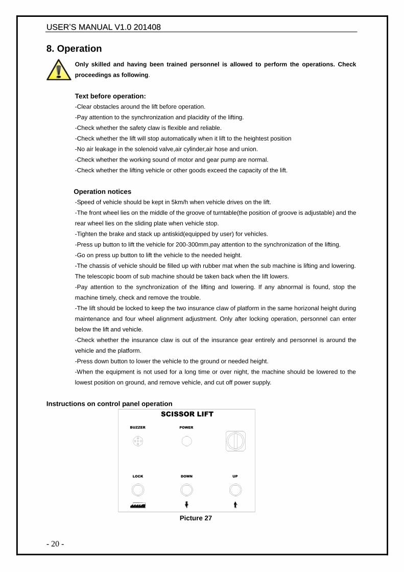
Instructions on control panel operation
Picture 27
DOWN
POWER
LOCK
BUZZER
UP
SCISSOR LIFT
UUSSEERR‟‟SS MMAANNUUAALL VV11..00 220011440088
- 21 -
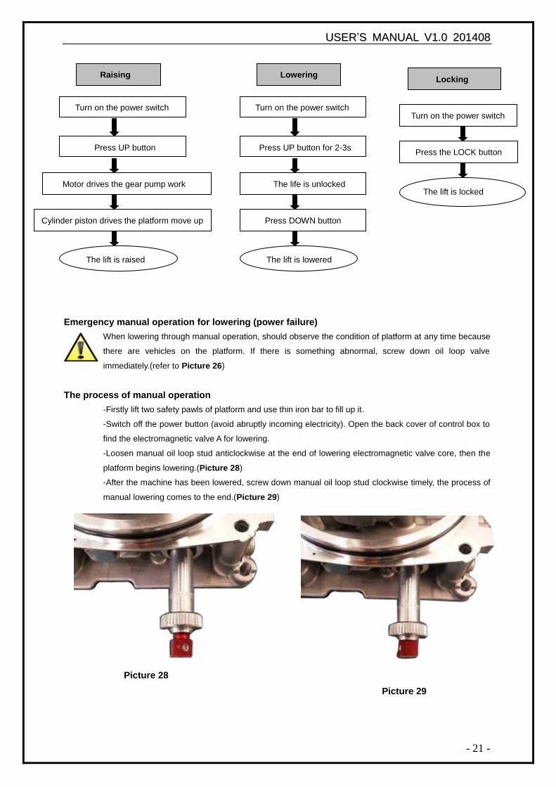
Emergency manual operation for lowering (power failure)
When lowering through manual operation, should observe the condition of platform at any time because
there are vehicles on the platform. If there is something abnormal, screw down oil loop valve
immediately.(refer to Picture 26)
The process of manual operation
-Firstly lift two safety pawls of platform and use thin iron bar to fill up it.
-Switch off the power button (avoid abruptly incoming electricity). Open the back cover of control box to
find the electromagnetic valve A for lowering.
-Loosen manual oil loop stud anticlockwise at the end of lowering electromagnetic valve core, then the
platform begins lowering.(Picture 28)
-After the machine has been lowered, screw down manual oil loop stud clockwise timely, the process of
manual lowering comes to the end.(Picture 29)
Raising
Turn on the power switch
Press UP button
Motor drives the gear pump work
The lift is raised
Cylinder piston drives the platform move up
Locking
Turn on the power switch
Press the LOCK button
The lift is locked
Picture 29
Picture 28
Lowering
Turn on the power switch
Press UP button for 2-3s
The life is unlocked
The lift is lowered
Press DOWN button
UUSSEERR‟‟SS MMAANNUUAALL VV11..00 220011440088
- 22 -
9. Maintenance and care
Skilled personnel only is allowed to perform the operations
Daily checking items
The user must perform daily check. Daily check of safety system is very important – the discovery of device failure
before action could save your time and prevent you from great loss, injury or casualty.
·Always wipe clean,keep the machine clean.
·Clear barriers and ground oil,keep the working condition clean.
·Check the integrity of each safety devices,ensure the motion is flexible and reliable.
·Check the reliability of limit switch motion.
·Check whether oil/air leakage of the machine exist.
Weekly checking items
·All bearings and hinges on this machine must be lubricated once a week by using an oiler
·Check the working conditions of safety parts.
·Check the amount of oil left in the oil tank. Oil is enough if the carriage can be raised to highest position. Otherwise,
oil is insufficient.
·Check whether the expansion bolts well anchored.
Monthly checking items
·The safety gear, the upper and lower sliding blocks and other movable parts must be lubricated one month.
·Check whether the foundation bolts well anchored.
·Check the abrasion and leakage of oil/air hose.
Yearly checking items
·The hydraulic oil must be replaced one time each year. The oil level should always be kept at upper limit position.
·.Check abrasion and damage of all the active parts.
·.Check the lubrication of roller. Lubricate it if drag phenomenon exist.
The machine should be lower to the lowest position when replace hydraulic oil, then let the old oil out,
and should be filtering the hydraulic oil.
-Each team checks the agility and reliability of pneumatic safety equipment.
Storage after use
When the machine does not use for a long time:
·.Cut off the power supply and air source and lubricate all the active parts.
·.Drain the hydraulic oil of oil cylinder,oil hose and oil tank.
·Sheathe the machine with dust-proof cover.
UUSSEERR‟‟SS MMAANNUUAALL VV11..00 220011440088
- 23 -
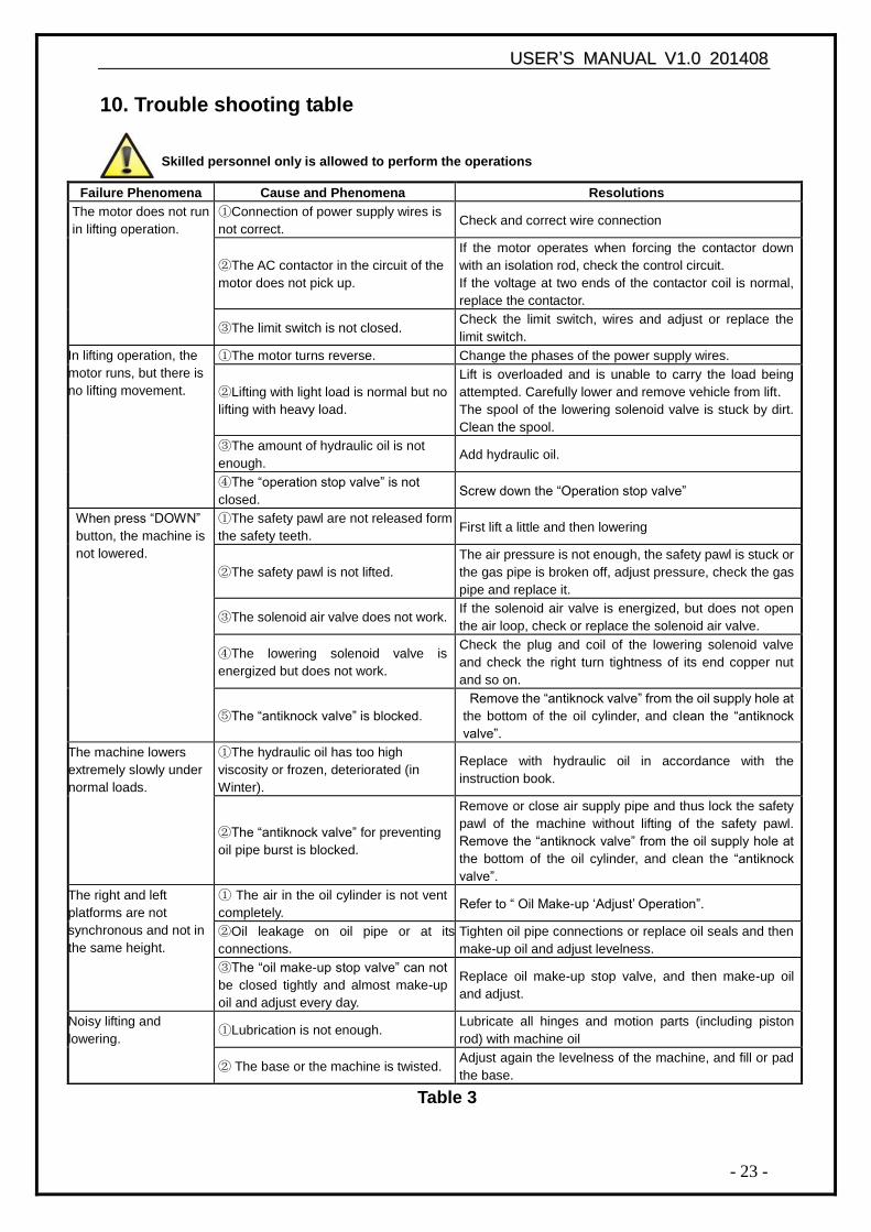
10. Trouble shooting table
Skilled personnel only is allowed to perform the operations
Table 3
Failure Phenomena Cause and Phenomena Resolutions
The motor does not run
in lifting operation.
①Connection of power supply wires is
not correct. Check and correct wire connection
②The AC contactor in the circuit of the
motor does not pick up.
If the motor operates when forcing the contactor down
with an isolation rod, check the control circuit.
If the voltage at two ends of the contactor coil is normal,
replace the contactor.
③The limit switch is not closed. Check the limit switch, wires and adjust or replace the
limit switch.
In lifting operation, the
motor runs, but there is
no lifting movement.
①The motor turns reverse. Change the phases of the power supply wires.
②Lifting with light load is normal but no
lifting with heavy load.
Lift is overloaded and is unable to carry the load being
attempted. Carefully lower and remove vehicle from lift.
The spool of the lowering solenoid valve is stuck by dirt.
Clean the spool.
③The amount of hydraulic oil is not
enough. Add hydraulic oil.
④The “operation stop valve” is not
closed. Screw down the “Operation stop valve”
When press “DOWN”
button, the machine is
not lowered.
①The safety pawl are not released form
the safety teeth. First lift a little and then lowering
②The safety pawl is not lifted.
The air pressure is not enough, the safety pawl is stuck or
the gas pipe is broken off, adjust pressure, check the gas
pipe and replace it.
③The solenoid air valve does not work. If the solenoid air valve is energized, but does not open
the air loop, check or replace the solenoid air valve.
④The lowering solenoid valve is
energized but does not work.
Check the plug and coil of the lowering solenoid valve
and check the right turn tightness of its end copper nut
and so on.
⑤The “antiknock valve” is blocked.
Remove the “antiknock valve” from the oil supply hole at
the bottom of the oil cylinder, and clean the “antiknock
valve”.
The machine lowers
extremely slowly under
normal loads.
①The hydraulic oil has too high
viscosity or frozen, deteriorated (in
Winter).
Replace with hydraulic oil in accordance with the
instruction book.
②The “antiknock valve” for preventing
oil pipe burst is blocked.
Remove or close air supply pipe and thus lock the safety
pawl of the machine without lifting of the safety pawl.
Remove the “antiknock valve” from the oil supply hole at
the bottom of the oil cylinder, and clean the “antiknock
valve”.
The right and left
platforms are not
synchronous and not in
the same height.
① The air in the oil cylinder is not vent
completely. Refer to “ Oil Make-up „Adjust‟ Operation”.
②Oil leakage on oil pipe or at its
connections.
Tighten oil pipe connections or replace oil seals and then
make-up oil and adjust levelness.
③The “oil make-up stop valve” can not
be closed tightly and almost make-up
oil and adjust every day.
Replace oil make-up stop valve, and then make-up oil
and adjust.
Noisy lifting and
lowering. ①Lubrication is not enough.
Lubricate all hinges and motion parts (including piston
rod) with machine oil
② The base or the machine is twisted. Adjust again the levelness of the machine, and fill or pad
the base.
UUSSEERR‟‟SS MMAANNUUAALL VV11..00 220011440088
- 24 -
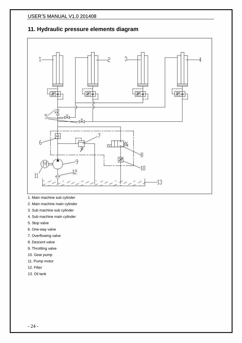
11. Hydraulic pressure elements diagram
1. Main machine sub cylinder
2. Main machine main cylinder
3. Sub machine sub cylinder
4. Sub machine main cylinder
5. Stop valve
6. One-way valve
7. Overflowing valve
8. Descent valve
9. Throttling valve
10. Gear pump
11. Pump motor
12. Filter
13. Oil tank
UUSSEERR‟‟SS MMAANNUUAALL VV11..00 220011440088
- 25 -
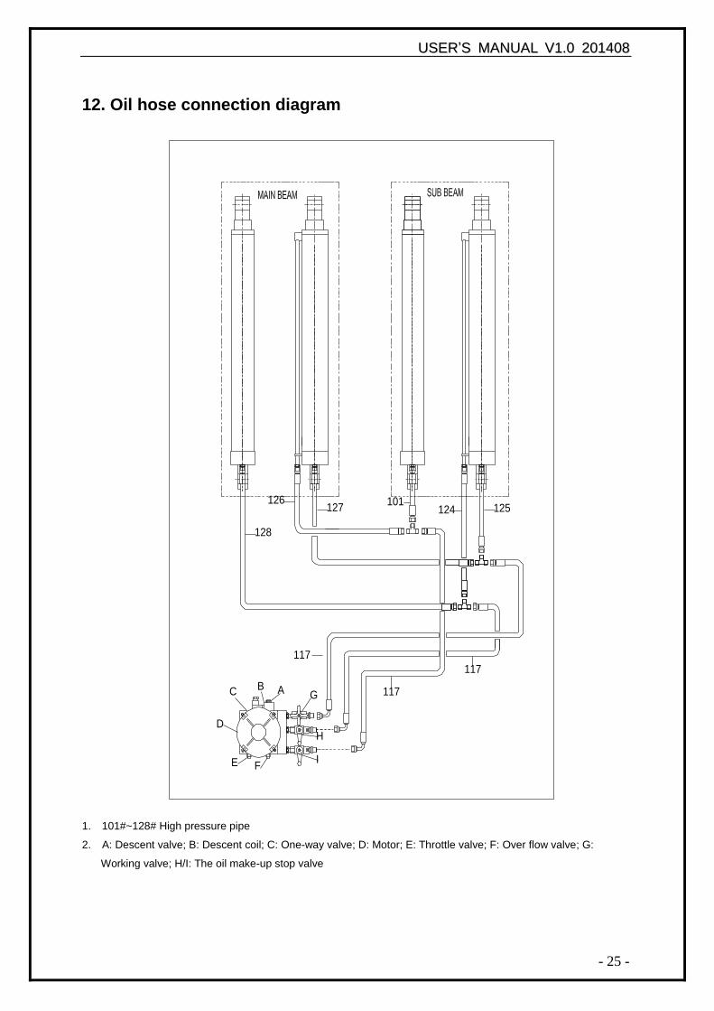
12. Oil hose connection diagram
1. 101#~128# High pressure pipe
2. A: Descent valve; B: Descent coil; C: One-way valve; D: Motor; E: Throttle valve; F: Over flow valve; G:
Working valve; H/I: The oil make-up stop valve
125
G
I
AB
E F
D
C
H
117
127 124126 101
128
117
117
UUSSEERR‟‟SS MMAANNUUAALL VV11..00 220011440088
- 26 -
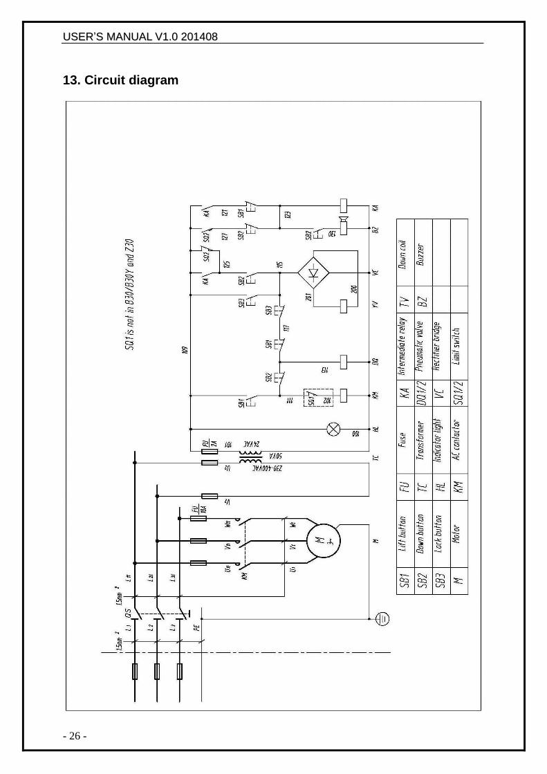
13. Circuit diagram
UUSSEERR‟‟SS MMAANNUUAALL VV11..00 220011440088
- 27 -
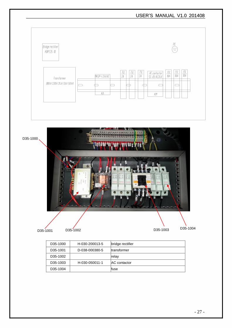
D35-1000 H-030-200013-5 bridge rectifier
D35-1001 D-038-000380-5 transformer
D35-1002 relay
D35-1003 H-030-050011-1 AC contactor
D35-1004 fuse
D35-1000
D35-1001 D35-1003 D35-1002 D35-1004
UUSSEERR‟‟SS MMAANNUUAALL VV11..00 220011440088
- 28 -
14. Gas loop diagram
UUSSEERR‟‟SS MMAANNUUAALL VV11..00 220011440088
- 29 -
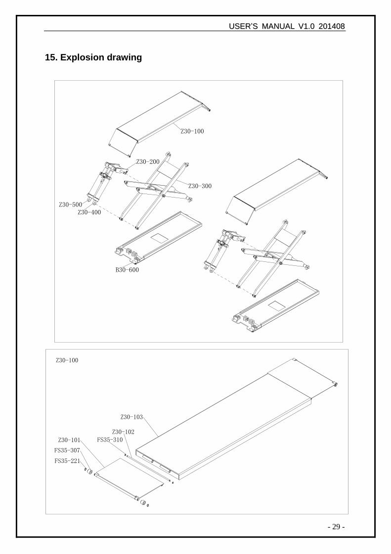
15. Explosion drawing
Z30-100
Z30-200
Z30-500Z30-400
B30-600
Z30-300
Z30-100
FS35-221
FS35-307
Z30-101 FS35-310Z30-102
Z30-103
UUSSEERR‟‟SS MMAANNUUAALL VV11..00 220011440088
- 30 -
Z30-100 platform complete
FS35-221 shaft snap ring Ø16
FS35-307 loading dock board roller
Z30-101 loading dock board
FS35-310 shaft snap ring Ø10
Z30-102 loading dock board stationary shaft Ø10
Z30-103 top plate
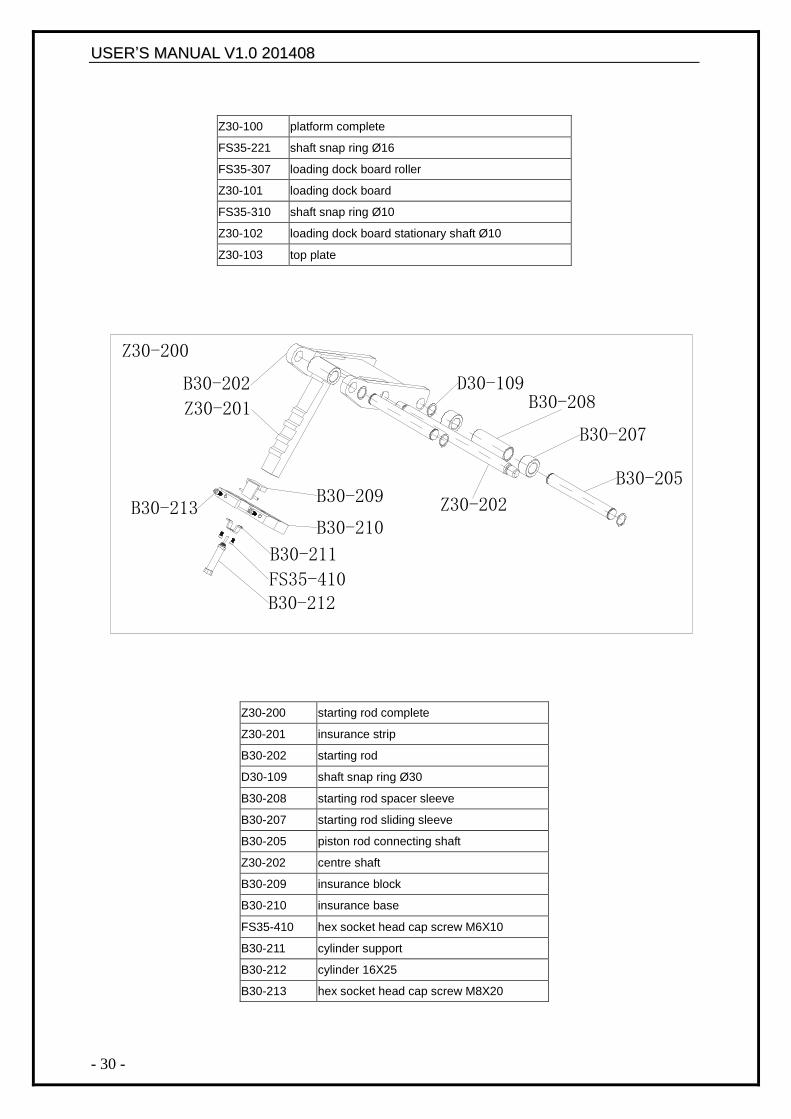
Z30-200 starting rod complete
Z30-201 insurance strip
B30-202 starting rod
D30-109 shaft snap ring Ø30
B30-208 starting rod spacer sleeve
B30-207 starting rod sliding sleeve
B30-205 piston rod connecting shaft
Z30-202 centre shaft
B30-209 insurance block
B30-210 insurance base
FS35-410 hex socket head cap screw M6X10
B30-211 cylinder support
B30-212 cylinder 16X25
B30-213 hex socket head cap screw M8X20
B30-209
B30-210
B30-211
FS35-410B30-212
Z30-200
Z30-201
B30-202 D30-109
B30-207
B30-208
B30-205
Z30-202B30-213
UUSSEERR‟‟SS MMAANNUUAALL VV11..00 220011440088
- 31 -
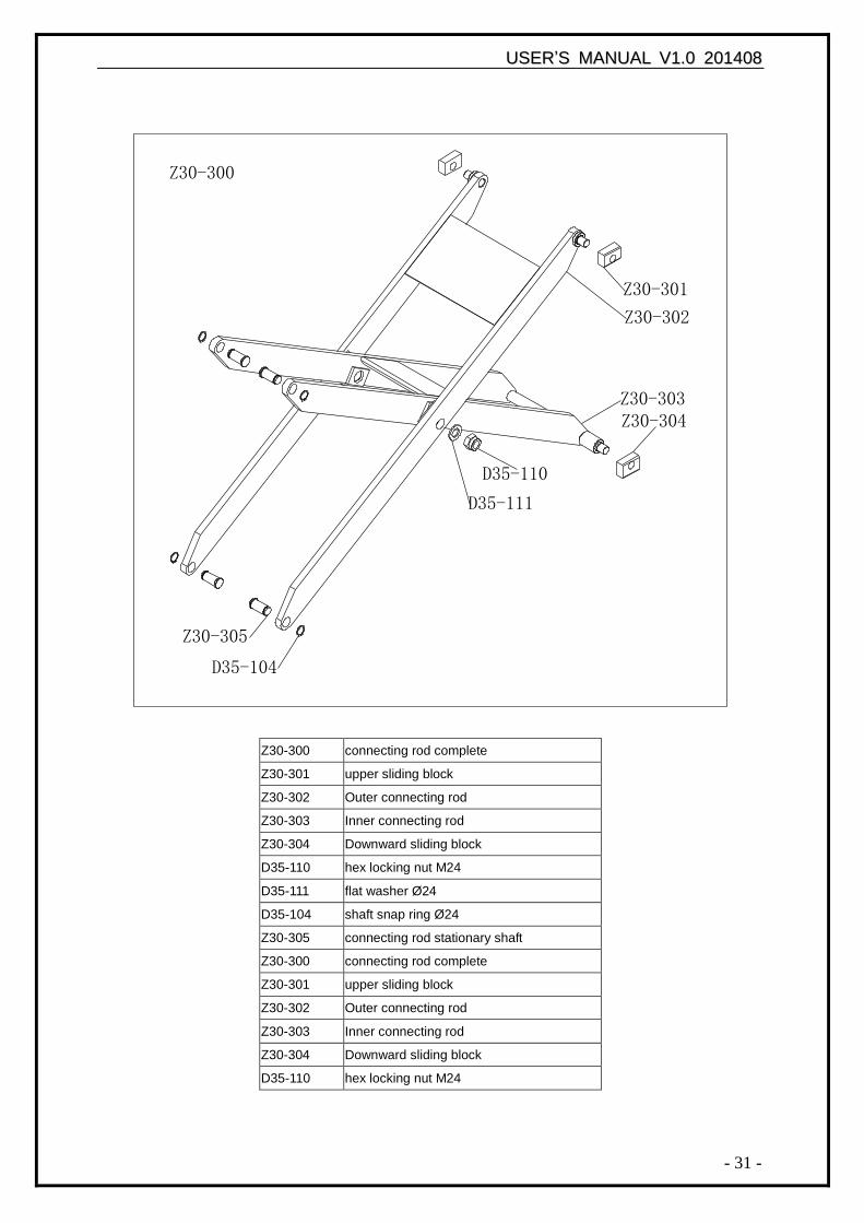
Z30-300 connecting rod complete
Z30-301 upper sliding block
Z30-302 Outer connecting rod
Z30-303 Inner connecting rod
Z30-304 Downward sliding block
D35-110 hex locking nut M24
D35-111 flat washer Ø24
D35-104 shaft snap ring Ø24
Z30-305 connecting rod stationary shaft
Z30-300 connecting rod complete
Z30-301 upper sliding block
Z30-302 Outer connecting rod
Z30-303 Inner connecting rod
Z30-304 Downward sliding block
D35-110 hex locking nut M24
Z30-300
Z30-301
Z30-302
Z30-303Z30-304
D35-110
D35-111
Z30-305
D35-104
UUSSEERR‟‟SS MMAANNUUAALL VV11..00 220011440088
- 32 -
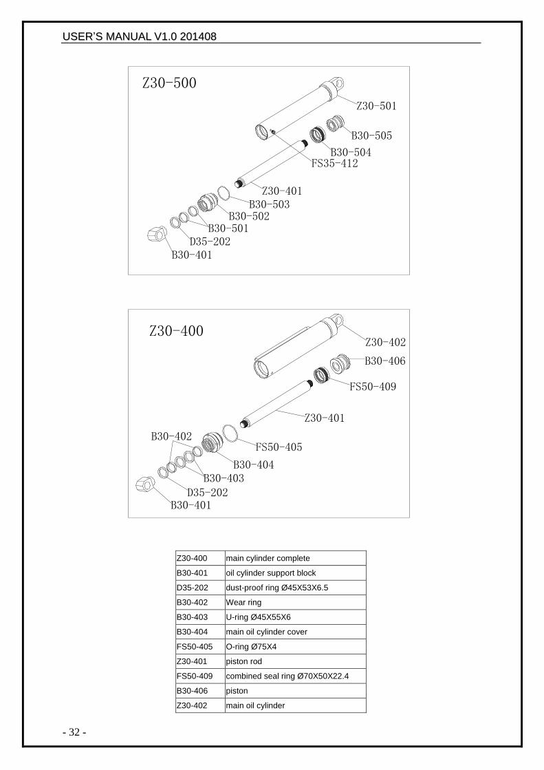
Z30-400 main cylinder complete
B30-401 oil cylinder support block
D35-202 dust-proof ring Ø45X53X6.5
B30-402 Wear ring
B30-403 U-ring Ø45X55X6
B30-404 main oil cylinder cover
FS50-405 O-ring Ø75X4
Z30-401 piston rod
FS50-409 combined seal ring Ø70X50X22.4
B30-406 piston
Z30-402 main oil cylinder
Z30-400
Z30-500
B30-401D35-202
B30-402
B30-403B30-404
FS50-405
Z30-401
FS50-409
B30-406
Z30-402
B30-401D35-202
B30-501B30-502
B30-503Z30-401
B30-504
B30-505
Z30-501
FS35-412
UUSSEERR‟‟SS MMAANNUUAALL VV11..00 220011440088
- 33 -
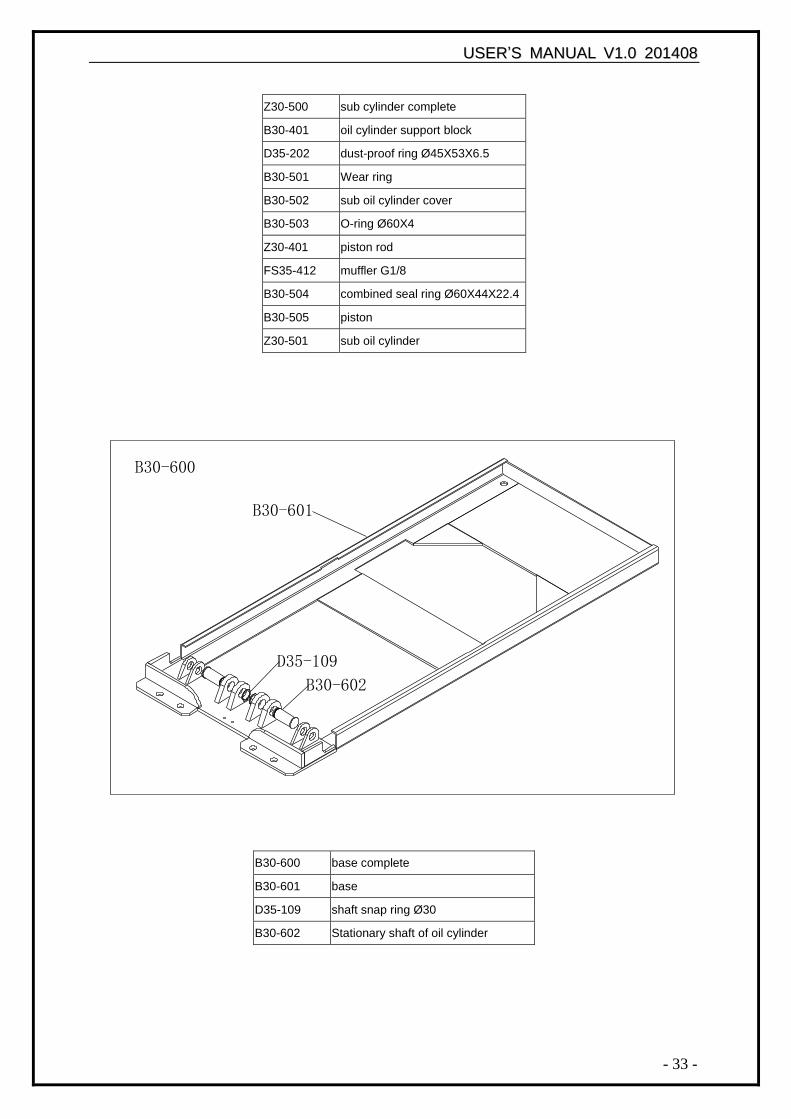
Z30-500 sub cylinder complete
B30-401 oil cylinder support block
D35-202 dust-proof ring Ø45X53X6.5
B30-501 Wear ring
B30-502 sub oil cylinder cover
B30-503 O-ring Ø60X4
Z30-401 piston rod
FS35-412 muffler G1/8
B30-504 combined seal ring Ø60X44X22.4
B30-505 piston
Z30-501 sub oil cylinder
B30-600 base complete
B30-601 base
D35-109 shaft snap ring Ø30
B30-602 Stationary shaft of oil cylinder
B30-600
B30-601
D35-109
B30-602
UUSSEERR‟‟SS MMAANNUUAALL VV11..00 220011440088
- 34 -
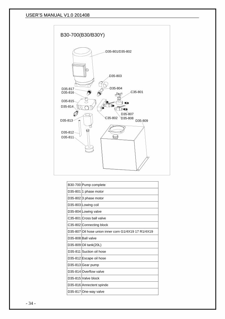
B30-700 Pump complete
D35-801 1 phase motor
D35-802 3 phase motor
D35-803 Lowing coil
D35-804 Lowing valve
C35-801 Cross ball valve
C35-802 Connecting block
D35-807 Oil hose union inner corn G1/4X19 17 R1/4X19
D35-808 Ball valve
D35-809 Oil tank(20L)
D35-811 Suction oil hose
D35-812 Escape oil hose
D35-813 Gear pump
D35-814 Overflow valve
D35-815 Valve block
D35-816 Annectent spinde
D35-817 One-way valve
B30-700(B30/B30Y)
D35-801/D35-802
D35-803
D35-804
D35-809
D35-811
D35-812
D35-813
D35-814
D35-815
D35-817D35-816
D35-807
D35-808
C35-801
C35-802
UUSSEERR‟‟SS MMAANNUUAALL VV11..00 220011440088
- 35 -
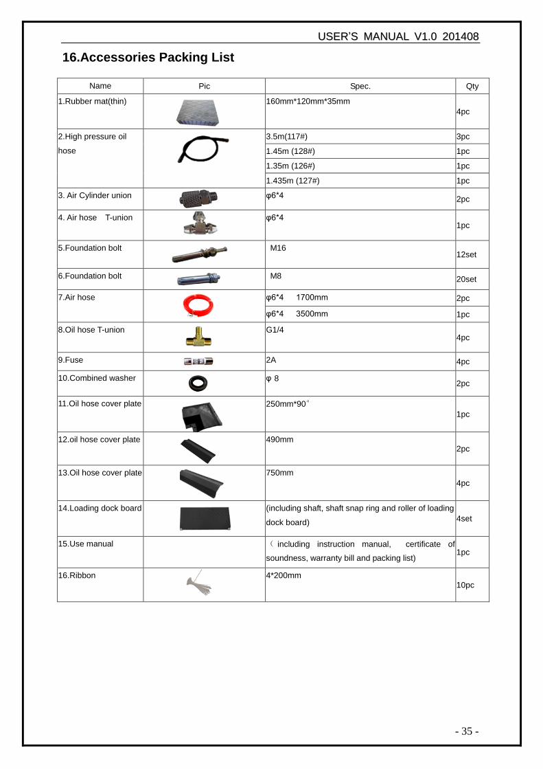
16.Accessories Packing List
Name Pic Spec. Qty
1.Rubber mat(thin) 160mm*120mm*35mm
4pc
2.High pressure oil
hose
3.5m(117#) 3pc
1.45m (128#) 1pc
1.35m (126#) 1pc
1.435m (127#) 1pc
3. Air Cylinder union φ6*4 2pc
4. Air hose T-union
φ6*4 1pc
5.Foundation bolt M16 12set
6.Foundation bolt M8 20set
7.Air hose
φ6*4 1700mm 2pc
φ6*4 3500mm 1pc
8.Oil hose T-union G1/4 4pc
9.Fuse 2A 4pc
10.Combined washer φ 8 2pc
11.Oil hose cover plate 250mm*90°
1pc
12.oil hose cover plate 490mm 2pc
13.Oil hose cover plate 750mm
4pc
14.Loading dock board (including shaft, shaft snap ring and roller of loading
dock board) 4set
15.Use manual ( including instruction manual, certificate of
soundness, warranty bill and packing list) 1pc
16.Ribbon 4*200mm
10pc