Embed Size (px)
Citation preview

Director, Tony Gee, UAE
Peter Revees-Toy
MIDAS Elite Engineer

MIDASELITE ENGINEER TALK
Case Studies of Steel Bridge Design using FEM Analysis

Contents
1. Introduction of Case Studies
1) Bahrain Bridge
2) Doha Metro Station Roof
3) Doha Metro Temporary Bridge
2. Other Project Applications
3. Useful Functionality

1. Introduction of Case Studies
1. Bahrain Bridge – 2012
Temporary works and erection stress analysis
Construction stages, lift off supports, support displacement and structural interaction
2. Doha Metro Roof – 2015
Permanent Works
Complex steel frame, connection modelling
3. Doha Metro Greenline – 2015
Temporary Bridge for Tunnel Boring Machine
Plate and frame analysis
1. General Description (32pt)1) Bahrain Bridge
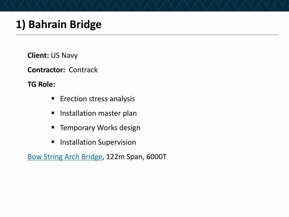
Client: US Navy
Contractor: Contrack
TG Role:
Erection stress analysis
Installation master plan
Temporary Works design
Installation Supervision
Bow String Arch Bridge, 122m Span, 6000T

1. General Description (32pt)1) Bahrain Bridge_What we needed to model
Construction stages
Cable Stressing and load transfer
Bridge beam interaction
1. General Description (32pt)1) Bahrain Bridge_How we modelled
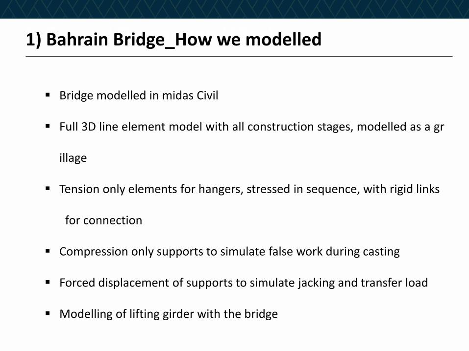
Bridge modelled in midas Civil
Full 3D line element model with all construction stages, modelled as a gr
illage
Tension only elements for hangers, stressed in sequence, with rigid links
for connection
Compression only supports to simulate false work during casting
Forced displacement of supports to simulate jacking and transfer load
Modelling of lifting girder with the bridge

1. General Description (32pt)1) Bahrain Bridge_Challenges of Modelling
Anomalies occur due to point connections
Arch to deck connection shows peak but within the foot connection
A common effect in most FE packages
Anomalies due to grillage
Transverse bending induced in the longitudinal deck members
Deck is actually a single member so the effect can’t occur

1. General Description (32pt)1) Bahrain Bridge_Construction Stage Analysis
• Enables accurate build up of forces
• Provides the build up of defection for the pre-camber
• Enables stresses in members to be checked at each step of the erection
process
• The CS analysis identified flexibility in the structure that the original
designer had not considered

1. General Description (32pt)1) Bahrain Bridge_Construction Stage Analysis

1. General Description (32pt)1) Bahrain Bridge_Iterative Pre-camber derivation
• Reason – arch stiffness changes with pre-camber
• Final shape modelled initially
• Deformed shape then recorded and reverse modelled
• This process was repeated five or six times to converge on the correct
pre-camber

1. General Description (32pt)1) Bahrain Bridge_Transfer to SPMT
• Tension is applied to the cables (approx 20kN)
• This nominal tensioning takes up the slack and the cables become
effective.
• The deck is still fully supported by the falsework at this time.
• The bridge is then jacked up by the SPMT at the bearing locations.
• The deck load is progressively transferred and the bridge sags to its final
profile.

1. General Description (32pt)1) Bahrain Bridge_Load transfer by reaction

1. General Description (32pt)1) Bahrain Bridge_Lifting beam interaction
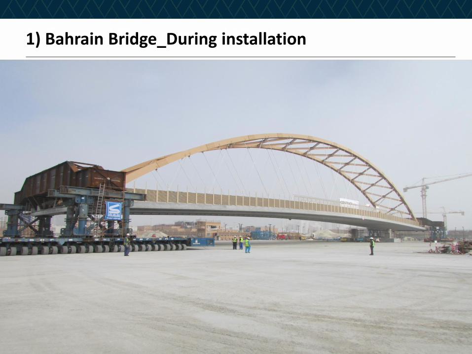
1. General Description (32pt)1) Bahrain Bridge_During installation
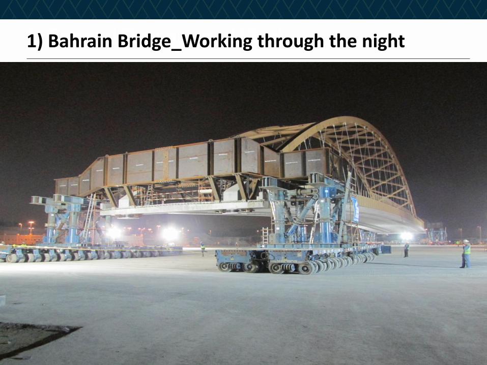
1. General Description (32pt)1) Bahrain Bridge_Working through the night
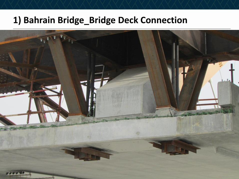
1. General Description (32pt)1) Bahrain Bridge_Bridge Deck Connection
1. General Description (32pt)1) Bahrain Bridge_Video
Demo – 09’51’’~11’56’’

1. General Description (32pt)2) Doha Metro Station Roof
• Major Station
• Building application but behaviour of a bridge
• Use of solid elements imported into line model for complex connections.
• Connection dxf exported from midas Civil, manipulated in CAD and
imported into midas FEA.
• Connection modelled in full in midas FEA, meshed and then inserted in
to midas Civil via MCT(Text fomate)

1. General Description (32pt)2) Doha Metro Station Roof_Doha Metro Line
1. General Description (32pt)2) Doha Metro Station Roof_Msheireb Station
• Major Station
• Building application but behaviour of a bridge
• Use of solid elements imported into line model for complex connections.
• Connection dxf exported from midas Civil, manipulated in CAD and
imported into midas FEA
• Connection modelled in full in midas FEA, meshed and then inserted in
to midas Civil via MCT(Text fomate)

1. General Description (32pt)2) Doha Metro Station Roof_Msheireb Station

1. General Description (32pt)2) Doha Metro Station Roof_Education City
1. General Description (32pt)2) Doha Metro Station Roof_What we needed to model
• Steel frame with complex geometry
• Correct connection relationships
• Temporary support condition during construction
• Complex full moment connections within the steel frame for stress
check
• Verification of constructability

1. General Description (32pt)2) Doha Metro Station Roof_How we modelled
• Full 3d frame model in midas Civil
• Use of construction stages to control articulation of supports
• Complex full moment connections modelled in midas FEA
• Connections imported back into Midas Civil frame model for direct
stress assessment

1. General Description (32pt)2) Doha Metro Station Roof_Step 1
• Divide the incoming elements to at connection
• Export the elements immediately connected to the node including
shape and thickness

1. General Description (32pt)2) Doha Metro Station Roof_Step 2
• Import into AutoCAD or similar (can be done in FEA directly)
• Rationalise the geometry
• Define additional connection elements, such as fin plates and splice
plates etc.
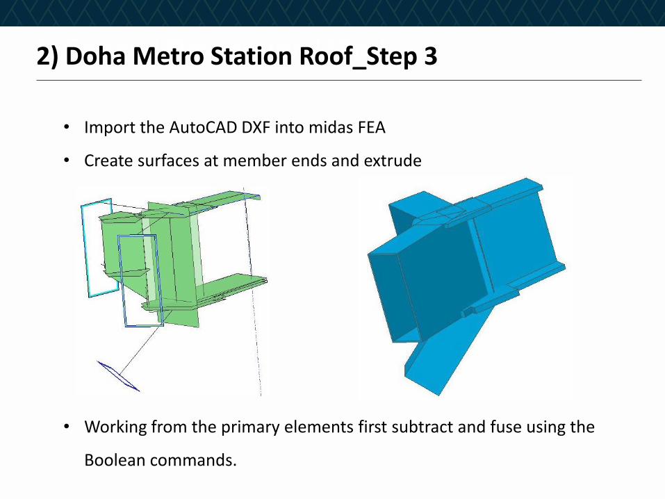
1. General Description (32pt)2) Doha Metro Station Roof_Step 3
• Import the AutoCAD DXF into midas FEA
• Create surfaces at member ends and extrude
• Working from the primary elements first subtract and fuse using the
Boolean commands.

1. General Description (32pt)2) Doha Metro Station Roof_Step 4
• Use the auto mesh function setting a mesh size similar to the plate
thickness.
• Depending on geometry set mesh controls a local discontinuities to help
mesher

1. General Description (32pt)2) Doha Metro Station Roof_Step 5
• Set material number to the same as midas Civil
• Re number the nodes and elements
• Export to MCT and then import in to midas Civil
• Maintain the same coordinate system through out.
• Connect the face of the solid to frame with rigid link.
• Large coordinates presented an glitch

1. General Description (32pt)
• Follow the same convention each time
• Don’t rush or cut corners
• Make us of local coordinate systems to ensure planar surfaces
• Label objects clearly including tools
• Use overlapping tools
• Subtract or fuse progressively
• Avoid narrow discontinuities
2) Doha Metro Station Roof_Solid modelling top tips

1. General Description (32pt)
TBM Bridge
• Spanning the excavation for the Blue Line
• 36m single span
• Shallow depth
• Minimises site operations
• Supports TBM and MSV in different configurations
• Line Model and Plate model
• Plate model enabled detailed consideration of deflections at different
fabrication stages
3) Doha Metro Temporary Bridge
1. General Description (32pt)
• Complex box steel box girder bridge
• Used in two different configurations
Ground bearing
Simply supported
• Models to allow for variations in loading and detailed connection
requirements
• Accurate plate model required for stiffness and local effects
3) Doha Metro Temporary Bridge_What we needed to model
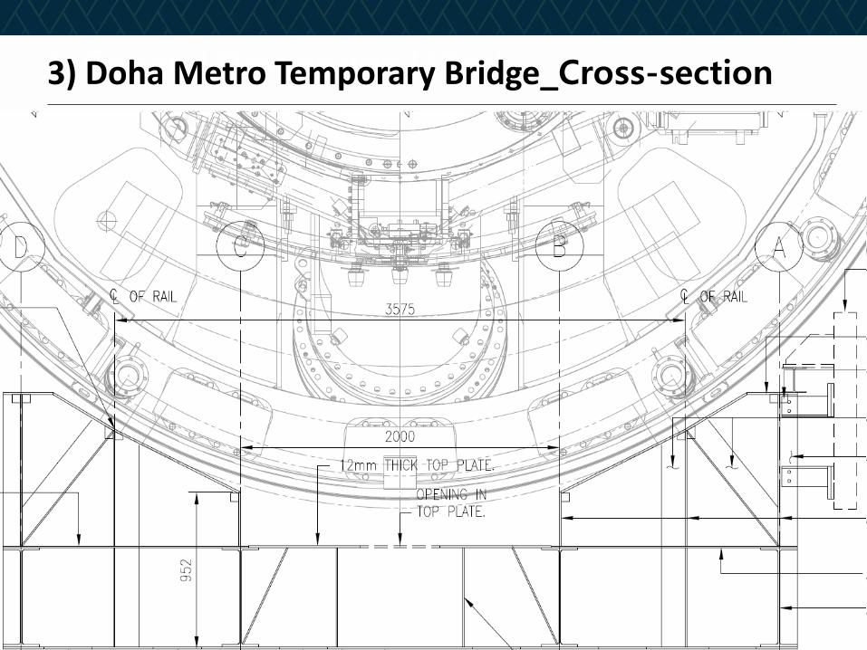
1. General Description (32pt)3) Doha Metro Temporary Bridge_Cross-section
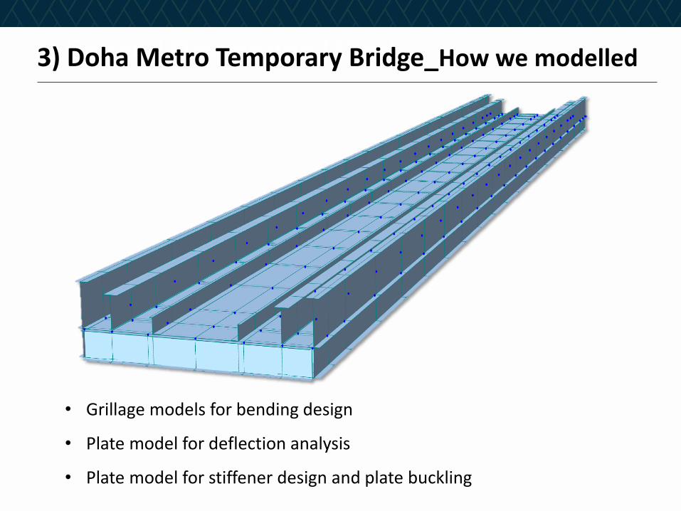
1. General Description (32pt)3) Doha Metro Temporary Bridge_How we modelled
• Grillage models for bending design
• Plate model for deflection analysis
• Plate model for stiffener design and plate buckling
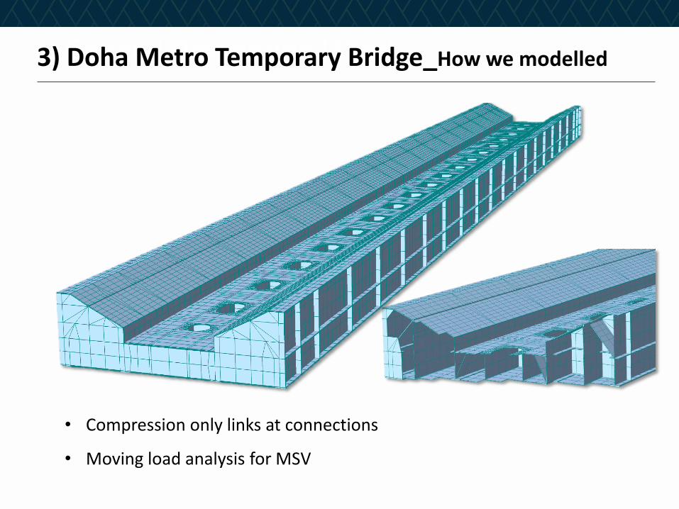
1. General Description (32pt)3) Doha Metro Temporary Bridge_How we modelled
• Compression only links at connections
• Moving load analysis for MSV

1. General Description (32pt)3) Doha Metro Temporary Bridge_Stress plot example
• Stress concentrations at links

1. General Description (32pt)3) Doha Metro Temporary Bridge_During Installation

1. General Description (32pt)3) Doha Metro Temporary Bridge_During Installation

1. General Description (32pt)3) Doha Metro Temporary Bridge_Bridge in use
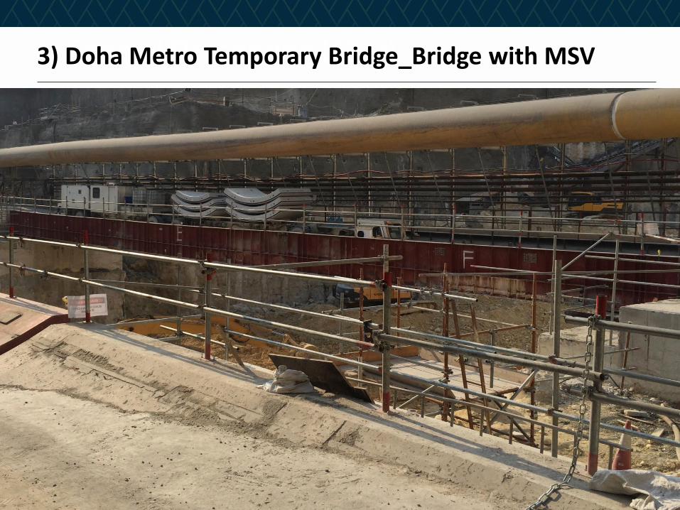
1. General Description (32pt)3) Doha Metro Temporary Bridge_Bridge with MSV

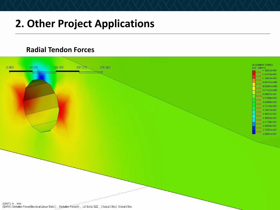
1. General Description (32pt)2. Other Project Applications
1. Assessment of radial forces in solid element modelling
• Use of embedded tendons
2. Assessment of equilibrium stresses between blisters in box girders
• Use of Embedded Tendons
3. Track Structure interaction

1. General Description (32pt)2. Other Project Applications
Radial Tendon Forces
1. General Description (32pt)2. Other Project Applications
Radial Tendon Forces

1. General Description (32pt)2. Other Project Applications
Embedded Tendons

1. General Description (32pt)2. Other Project Applications
Shear key failure

1. General Description (32pt)2. Other Project Applications
Track Structure Interaction
Incredibly Fast and Easy

1. General Description (32pt)3. Useful Functionality
• MCT Command Shell
• Structural Wizards
• Rendering and dxf output capability
• Use of Construction Stage to simulate changes in stiffness


![midas DShop Auto-drafting Module for midas Gen 01 02admin.midasuser.com/UploadFiles2/84/Dshop_catalog.pdf · Auto-drafting Module for midas Gen [midas Gen Design Results] [midas DShop](https://img.pdfslide.net/doc/110x75/5ade06cd7f8b9a9a768db6e7/midas-dshop-auto-drafting-module-for-midas-gen-01-module-for-midas-gen-midas-gen.jpg)