Embed Size (px)
Citation preview

1 | P a g e
MidNite Solar Classic
Owner’s Manual
This Manual covers models Classic 150, 200, 250
&250KS

2 | P a g e
The MidNite Solar Classic charge controller conforms to UL 1741, Safety for Inverters, Converters,
Controllers and Interconnection System Equipment for Use With Distributed Energy Resources,
Second Edition, May 7, 1999 with revisions through January 28, 2010 and
CAN/CSA C22.2 No. 107.1: 2001/09/01 Ed: 3 (R2006) Note: The Classic KS has not been evaluated by ETL.
Notice of Copyright
MidNite Solar's Classic charge controller User‘s Manual
Copyright ⓒ 2010 all rights reserved.
MidNite Solar Inc. reserves the right to revise this document and to periodically make changes to the
content hereof without obligation or organization of such revisions or changes unless required to do so
by prior arrangement.
Disclaimer
Unless specifically agreed to in writing, MidNite Solar Inc.
(a) Makes no warranty as to the accuracy, sufficiency or suitability of any technical or other
information provided in its manuals or other documentation.
(b) Assumes no responsibility or liability for loss or damage whether direct, indirect, consequential or
incidental, which might arise out of use of such information. The use of any such information will be
entirely at the user's risk.
Contact Information
Telephone: 360.403.7207
Fax: 360.691.6862
Email: [email protected]
Web: www.midnitesolar.com

3 | P a g e
Contents Scope .......................................................................................................................................................... 5 Introduction .............................................................................................................................................. 5 Classic Power Curves ............................................................................................................................... 7 Unpacking the Classic ............................................................................................................................ 10
Removing and installing the front cover on the Classic ..................................................................... 10
Mounting the Classic ............................................................................................................................. 12 Alternative Mounting .......................................................................................................................... 13
Dimensions...................................................................................................................................... 13 Sealed or Vented .................................................................................................................................. 13
Network Cable Routing and Installation Guidelines .......................................................................... 14 Battery Temperature Sensor Installation ............................................................................................. 17 Chassis Grounding ................................................................................................................................. 19
DC System Grounding ........................................................................................................................ 19
DC GFP (Ground Fault Protection) ..................................................................................................... 19 Disabling GFP ..................................................................................................................................... 20
Wiring the Classic .................................................................................................................................. 20 DC Terminal Connector ...................................................................................................................... 23
Over Current Protection and Wire Size Requirements ...................................................................... 23 Current Rating ..................................................................................................................................... 23
Temperature Current Limit ................................................................................................................. 23 Over Current Protection ...................................................................................................................... 24
Long Distance Wire Runs ................................................................................................................... 24 Maximum and Minimum Wire Size .................................................................................................... 24
Connecting the Classic to the Clipper .................................................................................................. 25
Commissioning the Classic .................................................................................................................... 26
Using the Classic Setup Screen's ........................................................................................................... 26 Setting Nominal Battery voltage ........................................................................................................... 27
Battery Charge Stages and Meanings ................................................................................................. 27
Bulk MPPT ..................................................................................................................................... 27 Absorb ............................................................................................................................................. 27
Float ................................................................................................................................................ 27 Equalize ........................................................................................................................................... 27
Adjusting Absorb, Equalize and Float Voltages .................................................................................. 27 Battery Size and Chemistry ................................................................................................................. 28 Battery Temperature Compensation .................................................................................................... 28
Calibrating Battery and PV Voltage ..................................................................................................... 28 Configuring DC Input Source ............................................................................................................... 28
Configuring the Classic for Photovoltaic Input Source ...................................................................... 29 Solar ................................................................................................................................................ 29 U- SET voc% .................................................................................................................................. 29 Slow Track ...................................................................................................................................... 29
Configuring the Classic for Wind Input Source .................................................................................. 30 Wind Track ...................................................................................................................................... 30
Setting the Date and Time ..................................................................................................................... 30 Setting Longitude and Latitude ............................................................................................................ 30 Configuring Auxiliary Input/Output .................................................................................................... 30

4 | P a g e
Aux 1 Function.................................................................................................................................... 32 Aux 2 Function. Output/Input ............................................................................................................. 33
Setting the MNGP features, Access the Version of software and Restore factory defaults ............. 33 Operating the Classic ............................................................................................................................. 34
Navigating the Menu's ........................................................................................................................ 34
Viewing Other MidNite Products on the Display ................................................................................ 35 Connecting Classic to Two MNGPs/Network cable ............................................................................ 35 Arc Fault ................................................................................................................................................. 35 View Faults and Warning's ................................................................................................................... 36
View Logged Data .................................................................................................................................. 37 Uploading New Firmware to the Classic .............................................................................................. 37
Updating Classic Firmware (Windows XP) ........................................................................................ 37
Connecting the Classic to the Internet ................................................................................................. 53 Networking.......................................................................................................................................... 53
Network Setup Through the MNGP ................................................................................................... 54 DHCP .................................................................................................................................................. 54
Static IP ............................................................................................................................................... 55 IP Address ....................................................................................................................................... 55
Subnet.............................................................................................................................................. 55 Gateway .......................................................................................................................................... 55 DNS 1 & 2....................................................................................................................................... 55
Web Access ......................................................................................................................................... 56 Local Network..................................................................................................................................... 56
Advanced ........................................................................................................................................ 56
MODBUS (Preliminary) ........................................................................................................................ 56 DISCLAIMER .................................................................................................................................... 56
Conventions: ....................................................................................................................................... 57
Dealer Information Screen .................................................................................................................... 82 Positive Ground systems ........................................................................................................................ 82
HyperVOC ™ ......................................................................................................................................... 82 HyperVOC ™ Origins ........................................................................................................................... 83 Troubleshooting ...................................................................................................................................... 83
Technical information ............................................................................................................................ 84
Specifications Electrical ......................................................................................................................... 84 Specifications Mechanical ..................................................................................................................... 85 Default Battery charge set points ......................................................................................................... 86 Optional accessories ............................................................................................................................... 86 Regulatory Approval .............................................................................................................................. 86
Warranty ................................................................................................................................................. 87 End of Warranty tune up ..................................................................................................................... 87
Aux 1 and Aux 2 Graphs/Jumpers ....................................................................................................... 88 Aux 1 Voltage-Time Relation (Relay/12v) ......................................................................................... 89
Aux 2 Voltage-Time Relation (PWM) ................................................................................................ 89
Classic Breaker sizing ............................................................................................................................ 90 Classic Menu Map .................................................................................................................................. 91

5 | P a g e
Scope
This Manual provides safety guidelines and installation information for the Classic charge controller. It
does not provide brand specific information about photovoltaic panels, batteries etc. Contact the
manufacturer of other components in the system for relevant technical data.
Introduction
The MidNite Classic charge controller is unique in its ability to be used for a great variety of DC input
sources. The Classic is designed to regulate DC input from PV, Hydro, Wind and other DC sources..
The Classic 150, 200 and 250 are designed to work with 12, 24, 36, 48, 60 and 72 volt battery banks.
The Classic250KS is designed to charge up to a 120V nominal battery bank.
The Classic can be installed stand alone or as a multi-unit networked installation.
Standard features of the Classic charge controller include:
*3 input operating voltage ranges 150, 200 and 250 VDC
*Multiple DC input options (example Solar, Wind or Hydro)
*Wizard driven setup interface including voice and help screens
*Graphical display
*Previous 180 days of operational data logged
*Internet ready
This Manual covers Classic 150, Classic 200 Classic 250 and the Classic 250KS. It covers the
installation, wiring and use of the Classic charge controller.
WARNING Warnings signs identify conditions or practices that could result in personal injury or loss of
life.
CAUTION Cautions identify conditions or practices that could result in damage to the unit or other
equipment.
MIDNITE SOLAR CHARGE CONTROLLER INSTALLATION GUIDELINES AND SAFETY
INSTRUCTIONS
This product is intended to be installed as part of a permanently grounded electrical system as shown in the
system configuration sections. The following important restrictions apply unless superseded by local or national
codes:
•The System's DC Negative conductor must not be bonded to earth ground. The Classic does this with its
internal Ground Fault Protection circuitry. The battery negative and ground are not bonded together directly but
are connected together by the Classic‘s internal GFP device. All negative conductor connections must be kept
separate from the grounding conductor connections. The equipment ground terminal inside the Classic must be
connected to Earth Ground for the internal DC-GFP to work. Continue
• With the exception of certain telecom applications, the Charge Controller should never be positive grounded.
6 | P a g e
• The Charge Controller equipment ground is marked with this symbol: • If damaged or malfunctioning, the Charge Controller should only be disassembled and repaired by a qualified
service center. Please contact your renewable energy dealer/installer for assistance. Incorrect reassembly risks
malfunction, electric shock or fire.
• The Charge Controller is designed for indoor installation or installation inside a weatherproof enclosure. It
must not be exposed to rain and should be installed out of direct sunlight.
For routine, user-approved maintenance:
• Turn off all circuit breakers, including those to the solar modules, batteries and related electrical connections
before performing any maintenance.
Standards and Requirements
All installations must comply with national and local electrical codes; professional installation is recommended.
The NEC in the USA requires a DC ground fault interrupter for all residential PV installations. NEC2011
requires an ARC FAULT detector on all charge controllers and inverters operating above 80VDC. Both of these
devices are built into the Classic.
DC and Battery-Related Installation Requirements:
All DC cables must meet local and national codes.
Shut off all DC breakers before connecting any wiring.
Torque all the Charge Controller‘s wire lugs and ground terminals to the specs found on page 19. Copper wiring must be rated at 75° C or higher.
Keep cables close together (e.g., using a tie-wrap) as much as possible to reduce inductance.
Ensure both cables pass through the same knockout and conduit to allow the inductive currents to
cancel.
DC battery over-current protection must be used as part of the installation on the input and output.
Breakers between the battery and the Classic must meet UL489 standards.
Breakers between the DC source and the Classic must meet UL1077 or UL489 standards.
Design the battery enclosure to prevent accumulation of hydrogen gas at the top of the enclosure. Vent the
battery compartment from the highest point to the outside. A sloped lid can also be used to direct the flow of
hydrogen to the vent opening. Sealed (AGM, Gel etc) batteries do not normally require ventilation. Consult your
battery manufacturer for details.
WARNING: PERSONAL PRECAUTIONS DURING INSTALLATION
WARNING BATTERIES PRESENT RISK OF
ELECTRICAL SHOCK, BURN FROM HIGH SHORT CIRCUIT CURRENT, FIRE OR
EXPLOSION FROM VENTED GASES. FOLLOW PROPER PRECAUTIONS.
Someone should be within range of your voice to come to your aid if needed.
Keep plenty of fresh water and soap nearby in case battery acid contacts skin, clothing, or eyes.
Wear complete eye protection. Avoid touching eyes while working near batteries. Wash your hands with
soap and warm water when done.

7 | P a g e
If battery acid contacts skin or clothing, wash immediately with soap and water. If acid enters an eye,
flood the eye with running cool water at once for at least 15 minutes and get medical attention
immediately following.
Baking soda neutralizes lead acid battery electrolyte. Keep a supply on hand in the area of the batteries.
NEVER smoke or allow a spark or flame in vicinity of a battery or generator.
Be cautious to reduce the risk of dropping a metal tool onto batteries. It could short the batteries or other
electrical parts that can result in fire or explosion.
Never wear metal items such as rings, bracelets, necklaces, and watches when working with a battery or
other electrical circuits. A battery can produce a short circuit current high enough to weld a ring or the
like to metal, causing severe burns.
Classic Power Curves
Figure 2.1
Figure 2.2

8 | P a g e
Figure 2.3
The graphs above represent the max power output for a given input for each Classic. Using and understanding
these power graphs will help maximize Classic‘s output power and aid in selecting wire and breaker/disconnects.
The built in set up wizard also helps select breakers and wire sizes. Notice that lower battery voltages and lower
PV input voltages result in higher continuous output power. The PV voltages listed are for reference and are not
intended to be the only PV voltages supported. The battery voltages listed show the most used battery bank
configurations. Other voltages are also supported. The Classic battery voltage parameters are fully user
adjustable.
For example: if you are using a Classic 250 and 48v battery bank, the maximum continuous output power
based on 25 degree C ambient is 55 amps when using a PV array that yields a Maximum Power Voltage of 180
volts. The same set up using a bit higher voltage modules that result in a 200V Maximum Power voltage will
result in only 53 amps. Although 55 to 53 amps is not a significant change, it does give you the idea that all
things being equal, lower voltages are a bit more efficient.
Below are the labels present on the Classic.

9 | P a g e

10 | P a g e
Unpacking the Classic
When you receive your Classic you will want to unpack it and make sure everything is there and in
good shape. Refer to Figure 1.1. Included in the Classic package should be:
*Classic charge controller
*Battery temperature sensor
**Snap on upper vent cover
*Knock out covers 4 screened
**Knock out covers 4 solid
*User‘s manual DVD, printed installation instructions
*1 ten foot custom USB cable
**Note. These items are optional email [email protected] for more information
If anything is missing or damaged please refer to Page 2 for details on contacting us.
Figure 1.1
Removing and installing the front cover on the Classic
Removing the front art deco cover is required to gain access to the wiring compartment.
Be aware there is a cable connecting the cover to the electronics. Do not pull hard or fast.
Damage will result.
To remove the front cover of the Classic in preparation for installation, remove the 4 Phillips head
screws with a #2 Phillips screwdriver. Lift the front half of the Classic casting off. You will need to
unplug the display cable. It works the same as any 10‖ long 6 conductor phone cable
To re-install the front cover of the Classic you will need to plug in the display cable and carefully route

11 | P a g e
it around the components on the circuit board as you set the cover in place. See Figure 1.2 Do not force
the cover if it does not seat into place easily stop and look for any cables or wires that may be
interfering. With the cover seated in place install the four Phillips screws with a #2 Phillips screwdriver.
Figure 1.2

12 | P a g e
Mounting the Classic
The following section covers typical mounting arrangements. If you require additional details that are
not covered here please contact us at technical support. The Classic is designed to be directly mounted
onto the MidNite Solar E-Panel as well as other installation methods. Mount in an upright position out
of direct sunlight when possible. The Classic has four one inch knock outs for your convenience they
are pre cast. The Classic has mounting and conduit location similar to other brands to facilitate ease of
upgrading older technologies to features available only on the Classic.
Mounting the Classic directly to the E Panel:
*Remove the front cover of the Classic.
*Install the mounting bracket on the E Panel and start the upper mounting screw into the bracket
leaving it about half way out so you can hang the Classic on this screw.
*Install the 1 inch close nipple into the E Panel as shown in the E-Panel directions. The 1‖ close nipple,
3 locknuts and 2 plastic bushings are included with each E-Panel. One locknut acts as a spacer.
*Carefully hang the Classic on the screw in the bracket and slide it over the close nipple see figure 1.3.
*Install the lock nut and bushing on the close nipple and tighten the screw in the mounting bracket.
*Don't install the front cover until you complete the wiring of the Classic.
Figure 1.3B Classic Mounted to side of E-Panel Figure 1.3C Nipple, locknuts and bushings
that come with every E-Panel
Figure 1.3A Charge controller
bracket mounted to the E-Panel. The
bracket comes with every E-Panel

13 | P a g e
Figure 1.3D Classic mounted to the side of a MidNite Solar E-Panel
Install locknut here to act as a spacer.
Alternative Mounting
To mount the Classic to a plywood surface use 1 1/2‖ wood screws in
the top key hole slot hole and the holes in the wiring compartment.
Taking care to make sure the Classic is Plumb and Level.
Dimensions
See page 40 for more details.
Sealed or Vented
The Classic has all the parts needed to convert to a sealed unit. If you
live in a dusty or salt air environment you may wish to seal the Classic.
Sealing the Classic does not make the unit water resistant. To seal the
Classic install the solid plastic knock out covers into any unused
knock outs and snap the upper vent cover onto the Classic as seen in

14 | P a g e
the photo below. Note that the Classic will be slightly de-rated (puts out less power) by sealing it. Refer
to the owner‘s manual for the specifications page for ratings in the sealed mode. Refer to Figure 1.4
and 1.5
Figure 1.4 Figure 1.5
Figure 1.6 Power wire hook up between the Classic and E-Panel
Network Cable Routing and Installation Guidelines
The Classic uses a network cable to communicate with other Classic's or other MidNite products. This cable is a
standard 6 conductor phone cable and simply plugs into the jack on the Classic labeled slave. Plug the other end
into the master jack on the second device. There is a plastic clamp located on the circuit board for routing the
network cables above the USB jack so they stay tied down out of the way. Refer to figure 1.7A and 1.7B
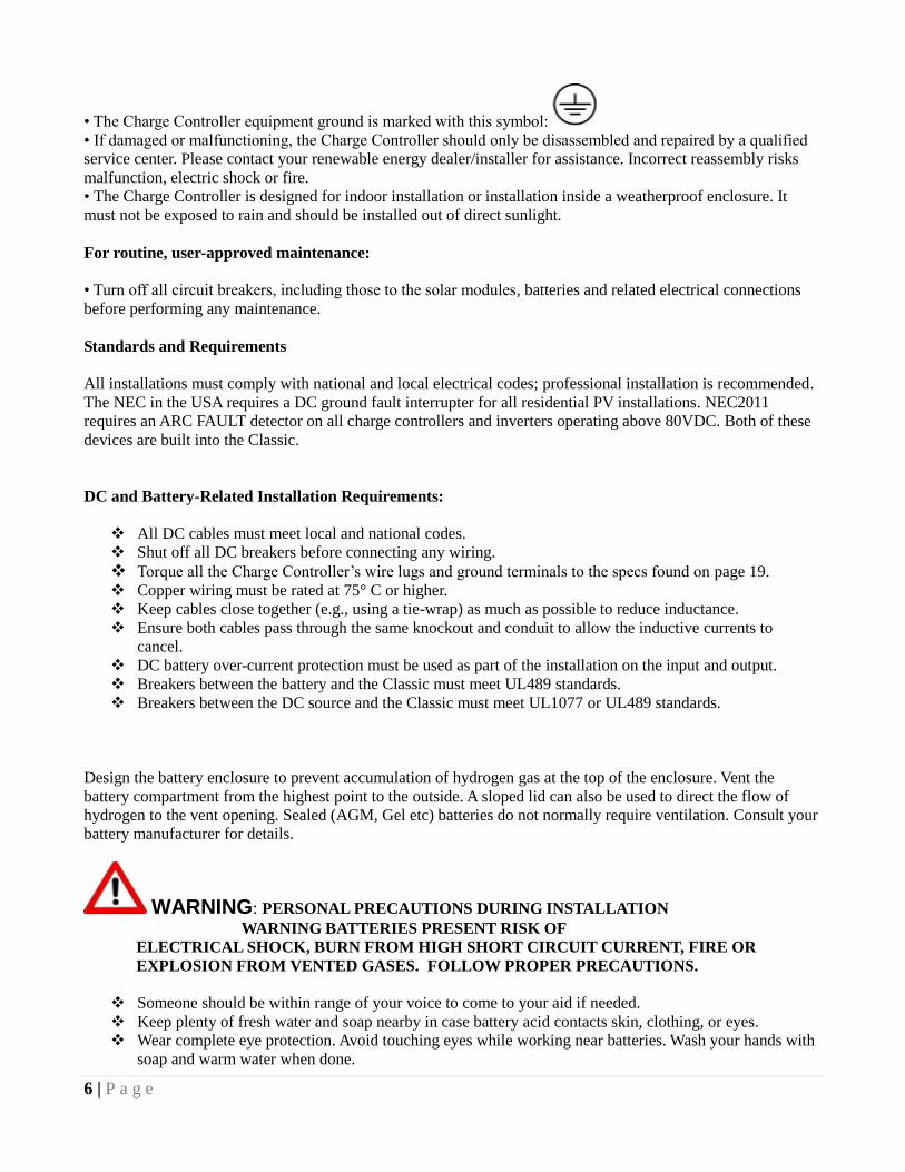
At this time you can use 2 Classics on one wind turbine if it is a 3 phase ac turbine. You need to use a
separate 3 phase bridge rectifier on each Classic otherwise they back feed each other and will blow up
one or both controllers.
Here is a wiring diagram of a typical install with two Classics
15 | P a g e

16 | P a g e
Figure 1.7A Master / Slave methods of hook up
Master Classic
Slave Classic

17 | P a g e
Figure 1.7B
Battery Temperature Sensor Installation
CAUTION - To reduce risk of injury, charge only deep-cycle lead acid, lead antimony, lead calcium,
gel cell or absorbed glass mat type rechargeable batteries. Other types of batteries may burst, causing
personal injury and damage. Never charge a frozen battery.
WARNING: RISK OF INJURY. To reduce the risk of injury, charge only properly rated (such as 6
V 12 V and 24 V ) lead-acid (GEL, AGM, Flooded, or Nickel Cadmium) rechargeable batteries. Other
battery types may burst, causing personal injury and damage.
WARNING: Explosion hazard during equalization, the battery generates explosive gases. Follow all
the battery safety precautions listed in this guide. Ventilate the area around the battery using ventilators
with brushless motors thoroughly and ensure that there are no sources of flame or sparks in the
vicinity.
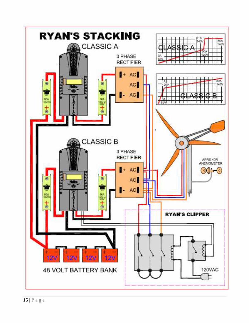
The Classic comes with a Battery temperature sensor which plugs into the jack beside the DC Terminal
connector labeled ―Battery Temp‖. Refer to Figure 1.8 Route the cable through the E-panel into the
battery box. Pick a battery in the middle of the bank and about half way up the side of the battery
thoroughly clean a spot off on the case. Then remove the protective tape from the sensor and adhere the
Battery Temp Sensor
Cable Clamp for
network cables
USB connector
10 foot USB cable is
included
Ethernet connector
18 | P a g e
temperature sensor to the battery. Some manufacturers use a double wall case on the battery. For
mounting a temp sensor to them please refer to the battery manufacturer's recommended procedure.
Figure 1.8
Insert BTS to the jack labeled BATTERY TEMP on the control board.
Figure 1.9

19 | P a g e
Before placing the Battery Temperature Sensor make sure battery surface is clean from any dust or
acids. Placement is not very critical.
Chassis Grounding
In all installations the Classic chassis should be connected to ground. For systems with a battery
breaker sized 60 amps and smaller 10 AWG (6 mm2) copper is generally sufficient. For systems with a
battery breaker sized 100 amps and smaller 8 AWG (10 mm2) copper is required. For grounding
conductor requirements on your specific installation please consult your local electrical code. The
chassis grounding terminal is in the upper right corner of the electrical connection compartment see
Figure 2.0
Figure 2.0
DC System Grounding
The Classic charge controller is designed to work with negatively grounded or ungrounded power
systems. In grounded systems, dc negative may be connected to ground either externally or by using
the Classic‘s internal grounding jumper, shown on figure 2.1. The internal grounding jumper should
only be installed when the Classic‘s GFP is enabled. In a system with multiple charge controllers the
grounding jumper should only be installed on one charge controller. If the charge controllers have
different voltage ratings, install the jumper on the charge controller with the highest voltage rating.
DC GFP (Ground Fault Protection)
The Classic has internal ground fault protection (GFP) built in. Since 2008 the NEC requires a DC-GFP
on all PV systems in the USA. The built in DC-GFP eliminates the need to purchase and install an
external DC-GFP. If the internal grounding jumper is installed in a Classic, the battery negative and DC
source negative must not be connected to the system grounding conductor anywhere in the system.
Grounding of these circuits will defeat the GFP function. In a network with multiple Classics, all
Classics must have the internal grounding jumper installed and enabled. The factory setting will make a

20 | P a g e
DC negative to System Ground connection in the Classic charge controller. The GFP function will need
to be disabled for an ungrounded DC system.
Figure 2.1
The Ground fault device is simple to understand
and use. The Classic DC-GFP works a bit
different than others. It detects a fault between
battery/PV negative and earth ground just like the
breaker DC-GFP system. The difference with the
Classic is that it simply turns off when a ground
fault is detected. This is different than
disconnecting the PV plus circuit. This trick of
turning off was first pioneered by another charge
control company as an alternative to $100
external circuit breaker assemblies. The Classic‘s
system consists of a PTC that is between the
Negative and Ground internally in the Classic. A PTC is basically a type of resistor with a 1 ohm value
that when loaded to three quarters of an amp will heat up and go to a very high resistance looking like
an open circuit. One of the 3 Classic microprocessors watches the PTC and when it sees a high
resistance it will disable the Classic. The ground fault device will then require a manual reset. The PTC
is self healing though so no fuses to change. This method meets the requirement for DC ground fault
protection in the National Electric Code.
To disable the internal Ground Fault Protection function, the jumper labeled GFP needs to be removed,
and the GFP function must be disabled in the TWEAKS menu. See section below for instructions.
To reset the internal GFP function after detection has occurred, fix the actual ground fault, then turn
OFF Classic and turn it back ON. Do this by turning the external battery breaker to OFF position and
then to ON position.
Disabling GFP
The GFP feature should only be disabled to operate the Classic in an ungrounded power system or in
systems where GFP is not required.
Press Main Menu
Scroll to the right or left until TWEAKS is highlighted and press ENTER
In TWEAKS press the right soft key to get to the BITS menu
In BITS scroll until GFP is highlighted
Use the up and down arrow keys to toggle between on and off
Press ENTER to save
Wiring the Classic
WARNING: Shock hazard. Disconnect the batteries and input power before opening the Classic
front cover
The Classic should be wired by a qualified professional and needs to meet all applicable electrical
codes. Always make sure all source and battery circuits are de energized and wait 5 minutes before

21 | P a g e
working on the wiring in the Classic. The Classic has 2 common neutral (negative) terminals.
Therefore, only one neutral conductor is required to run from the E-Panel and terminate on either (or
both) common neutral terminal. The Positive DC source wire goes to the PV+ Turbine+ screw. The
Positive Battery DC wire goes to battery + terminal. Torque the terminal screws to the specs below.
To connect the wiring to the Classic:
Ensure the DC source and Battery are disconnected
Connect a grounding conductor between the Classic and system ground
Ensure the breaker between the battery and Classic meets UL489 standards.
Ensure the breaker between the dc source and Classic meets UL1077 standards.
Connect the DC source and Battery wire to the Classic
Connect any communications cable or auxiliary input/output wires
Torque terminal connector screws to the following specs
The Torque specs on the DC terminal connector (big blue terminal connector) are:
Up to #10 AWG torque to 25-35 inch pounds.
#8 AWG torque to 30-40 inch pounds.
#6 AWG or above. Torque to 40-50 inch pounds.
Figure 2.1

22 | P a g e
Figure 2.2

23 | P a g e
DC Terminal Connector
Figure 2.4
The Classic's DC terminal connector is located on the circuit board as shown in. The connector will
take up to a #4 AWG. 4AWG THHN wire when installed in the Classic. The MidNite E-Panel is rated
for over 100 amps and is therefore suitable for the highest power Classic 150.
Over Current Protection and Wire Size Requirements
The over current devices, wiring, and installation methods used must conform to all electrical codes
applicable to the location of installation. Wiring needs to be protected with proper strain relief clamps
and or conduit. See page 49 for a breaker and wire size chart.
The network cables, USB cable, BTS cable and auxiliary input/output cables should run in a different
conduit to preserve their signal. When installing the Classic in a MidNite E-Panel, it is acceptable to
run all wiring through the same knockout hole. It is legal to run signal and power wires together as long
as all wiring is listed for the highest voltage to be encountered.
Current Rating
The Classic limits the output current to the maximum for the model you have.
The Classic current ratings are:
Classic 150v - 96 amps maximum
Classic 200v - 79 amps maximum
Classic 250v - 62 amps maximum
Temperature Current Limit
The Classic has a current limit component which interacts with the temperature of the charge controller.
If the Classic is exposed to extremely hot ambient conditions the out put current will be reduced

24 | P a g e
automatically to keep the charge controller safe, if the orange LED comes on, on the MNGP it means
that the Classic is in current limit mode. If you believe the Classic is not hot and the orange LED is on,
most likely the current limit set point is too low. To check this follow steps bellow.
Press Main Menu
Highlight CHARGE menu and press the Enter Button
Press the upper right soft button
Press the right arrow key to highlight Out Amps column
Use the up and down arrow keys to change the current limit.
Over Current Protection
The Classic must have over current protection to protect wiring from over current events. A means of
disconnect must be installed on the DC in and DC out of the Classic. Consult your local codes to
determine over current ratings. The breaker between the battery bank and the Classic must conform to
UL489. The breaker between the DC source and the Classic must conform to UL1077 or UL489. The
NEC requires 1.56 times short circuit current for PV over current protection. This is reduced to 1.25
times when using a breaker rated for continuous duty. All MidNite Solar breakers are
hydraulic/magnetic and are rated for continuous duty. No de-rating is required for the output breaker
when using MidNite Solar breakers.
PV in particular will be capable of producing more current than its name plate rating in extreme
situations so the safe minimum wire size should be selected for the PV array maximum short circuit
current. Please consult PV manufacturer for specifications. The US National Electrical Code requires
1.56 times the PV short circuit current for wire size on the PV input. Output wire size follows the NEC
guidelines. Typical wire size for output is 6AWG for the Classic250 and 4AWG for the Classic200 and
150 but check all de-ratings for your wire type and installation method.
Long Distance Wire Runs
The Classic offers some unique opportunities if you are faced with longer than normal wire runs
between the DC source and the Classic. The Classic comes in 3 input voltage ranges letting you design
a DC source at a higher voltage if it is beneficial. For example let‘s say you have a 300 ft run from a
PV array to the Classic you could wire for an open circuit voltage close to 250vdc accounting for the
coldest temperature you will encounter. This will allow you to run a smaller gauge than with a lower
voltage charge controller. The efficiency of a high voltage Classic is less than the lower voltage
versions, so you need to weigh the benefit. If this sounds too complicated use this rule of thumb in
selecting the proper Classic. PV runs up to 100 feet, use the Classic 150. Runs up to 180 feet, use the
Classic 200. Above 180 feet use the Classic 250 or 250KS.
If the wire size between the DC source and the Classic is larger than the Classic's DC terminal
connector you can use a splicer block or similar connector to reduce down to #4 AWG close to the
Classic. The MidNite E-Panels are supplied with a PV input busbar that accepts up to 1/0 wire.
Maximum and Minimum Wire Size
The Classic DC terminal connector will accept wire from #14-#4 AWG

25 | P a g e
Connecting the Classic to the Clipper
The Classic will work in conjunction with either of the MidNite Solar Clipper's when available. To
connect the Classic to a Clipper you need to plug a MidNite network cable (standard 6 conductor phone
cable) into the jack labeled MASTER/IN Clipper and the other end into the jack labeled SLAVE/OUT
on the Classic. The DC output of the Clipper will go to The DC input terminals on the Classic. Refer to
the figures below.
Figure 2.5
Figure 2.6
Classic network
To Classic

26 | P a g e
Commissioning the Classic
The Classic will enter into the setup wizard upon initial power up. If the Classic does not enter into the
setup wizard or you want to enter the wizard at any time follow these steps to get into the setup wizard.
Press the Main Menu button.
Scroll Left or Right until Wizard is highlighted and press the Enter button.
Follow the on screen instructions through to the end.
Using the Classic Setup Screen's
The Classic setup wizard will walk you through the set up process. Below is a description of the steps.
DO YOU WANT PASSWORD
ENABLED?
PASWORD WILL BE 142
YES NO
Sets the password On Classic Settings
CONNECTED TO
CLASSIC 150
Tells you which classic model it is
IS THIS A
GRID TIED SYSTEM
(BATTERY BACKUP)
YES NO
This menu will determine how to treat batteries
differently. sealed batteries lower voltage for
grid tied
TIME DATE
24:00:00 01/10/2010
Set time and date, this is important because
Classic will automatically know at what time to
wake up and go to sleep mode
(Sunrise/sunset using Astronomical formulas)
BATTERY CHEMISTRY
FLOODED LEAD ACID
ENTER
Sets up battery temp compensation and absolute
maximum charge voltages regardless of temp
BATTERY BANK VOLTAGE
48
Selects between different voltage configurations
on the system, increments of 12 volts (12v, 24v,
36v, 48v, 60v, 72v)
DO YOU KNOW THE BATTERY BANK AMP HR
CAPACITY
YES NO
Helps set Absorption time and EQ defaults
WHAT IS THE VOLTAGE
OF AN INDIVIDUAL
BATTERY
6
This is necessary for the set up software to help
figure out battery capacity
SET CURRENT LIMIT
80
ENTER TO CONTINUE
Sets classic‘s max output current
CONTROLLER MODE
SOLAR WIND HYDRO
SCROLL < > TO SELECT
THEN PUSH ENTER
Selects classic‘s mode. This can be changed in
the mode menu
STC
MODULE POWER
210 ^ WATTS
Photovoltaic module power rating

27 | P a g e
STC
VOC RATING
44.3^ VOLTS
Photovoltaic module voltage rating
STC
ISC RATING
Photovoltaic module current rating
Setting Nominal Battery voltage
Upon initialization the Classic will display battery
To set up the Classic to a preset battery voltages (e.g. 12v, 24v… 48v) follow the steps below.
Press Main Menu
Scroll to the left until Charge is highlighted and push the Enter button
Highlight Volts and press the Enter button
Press the Right soft key
Scroll up and down to select the desirable battery voltage
Battery Charge Stages and Meanings
Bulk MPPT
This stage of the Classic means; that the Classic will be putting out as much current as it can trying to
charge the batteries to the absorb voltage set point. This is also known as constant current mode.
Absorb
This stage means that the Classic will maintain the absorb set point voltage until the batteries are charged
or it reach Float stage. At this stage the classic is not putting out maximum current, as that would increase
the battery voltage over the Absorb set point. This is also referred to as constant voltage mode.
The absorb time is proportional to the bulk time. (i.e. the time bulk takes to reach the absorb voltage.) The
battery it‘s considered ―full‖ at the end of the absorb charge cycle.
Float
A Float cycle follows after the Absorb cycle is completed; Float is displayed on the screen. Battery vol-
tage is held at the float voltage set point, float time can be changed by the user.
Equalize
Equalization function has to be enabled by the user, refer to page 25. The intent of an equalization charge
is to bring all battery cells to an equal voltage by a deliberate overcharge. The goal is to return each bat-
tery cell to its optimum condition through a series of voltage controlled chemical reactions inside the bat-
teries.
Adjusting Absorb, Equalize and Float Voltages
Setting the Classic though the wizard will set Absorb, Float and EQ to the factory default set voltage to
the specified battery type. (E.g. Flooded Lead, Gel...) These voltages are fully adjustable, just follow the
steps below.
28 | P a g e
Press Main Menu
Scroll to the left until Charge is highlighted and push the Enter button
Highlight Volts and press the Enter button
Use left and right arrows keys to highlight the set point voltage to adjust
Use up and down arrow keys to lower or raise the voltage
Press the Enter button to save the new voltages.
Battery Size and Chemistry
The Classic supports a variety of battery chemistries including; Flooded lead acid, sealed – AGM, gel cell
and Nickel Cadmium. These different types of batteries have different charging parameters. These
parameters are crucial for long- time battery life. Go through the WIZARD to select the battery type of
your system. If you replace the batteries for a different type make sure you change the type on the
WIZARD. That is the only place where the battery type can be changed.
Battery Temperature Compensation
The Classic comes with a battery temperature sensor (BTS). This sensor raises or lowers charge voltage
based on temperature. Connect BTS to the BATT TEMP jack. (Refer to fig 1.7B and 1.9) Battery
temperature menu appears as T-Comp in the BATTERY MENU. In this menu you can change the voltage
compensation as needed. If the BTS is disconnected or shorted the Classic will automatically use the
default charge voltages non-compensated.
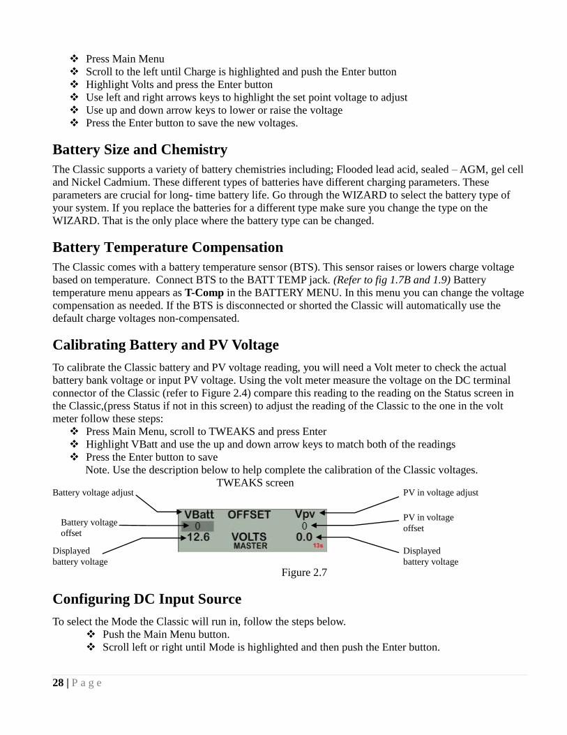
Calibrating Battery and PV Voltage
To calibrate the Classic battery and PV voltage reading, you will need a Volt meter to check the actual
battery bank voltage or input PV voltage. Using the volt meter measure the voltage on the DC terminal
connector of the Classic (refer to Figure 2.4) compare this reading to the reading on the Status screen in
the Classic,(press Status if not in this screen) to adjust the reading of the Classic to the one in the volt
meter follow these steps:
Press Main Menu, scroll to TWEAKS and press Enter
Highlight VBatt and use the up and down arrow keys to match both of the readings
Press the Enter button to save
Note. Use the description below to help complete the calibration of the Classic voltages.
TWEAKS screen
Figure 2.7
Configuring DC Input Source
To select the Mode the Classic will run in, follow the steps below.
Push the Main Menu button.
Scroll left or right until Mode is highlighted and then push the Enter button.
Battery voltage adjust
Battery voltage
offset
Displayed
battery voltage
PV in voltage adjust
PV in voltage
offset
Displayed
battery voltage

29 | P a g e
The ON/OFF has to be set to OFF in order to change the operational mode. Scroll to the right to highlight
the word ON or OFF and use the up and down keys to change it to OFF. Push the Enter button to save this
change. Now you can scroll to the right and highlight the mode under Function. Scrolling up or down
changes the modes. Once a mode is selected push the Enter button to save this change. Then you can use
the right soft key to select ―setup‖. This would be where you will manually set up any parameters specific
to the mode you selected.
Configuring the Classic for Photovoltaic Input Source
The Classic has more than one mode to be used for Photovoltaic arrays; USET, O&P Solar, SOLAR and
Solar 1.
Solar
This is the ultra-fast, Maximum Power Point tracking mode. It finds MPP in less than half a second with a
precision of +-5 watts; this is the default solar mode. Use this mode except in special cases. To select this
mode just select Solar from the list in the MODE Menu.
There is one parameter of this mode which can be configured.
Interval- In minutes. Is the maximum amount of time in between sweeps. We recommend to set
the time to 15 min. let the Classic figure out if the input power has changed, in which case the
Classic will automatically sweep for a new MPP.
1 Note. Setting Interval to 0 will set the Classic to only do an initial sweep down to battery voltage when
turned ON. However it will still do automatic sweeps.
2 Note. The Classic does automatic sweeps thought out the day to optimize maximum output power.
Every time there is a change in the input power of more than 10% the Classic will do a sweep, this could
be caused by a cloud passing by or shadows of a tree branch.
U- SET voc%
U- SET Lets the user pick the VOC % meaning that for any specific reason the VOC should stay constant
it will, only while in BULK MPPT charging state, after going to absorb or float VOC% will change to
maintain the batteries at their absorb voltage set point. (See pg. 31) This mode will not automatically find
Maximum Power Point. U-SET will also let you do an interval. But it is utilized differently. To set
Interval time or to set VOC% do the following:
Press main menu and scroll to MODE, press Enter
Highlight ON/OFF and select OFF
Scroll to the right and press the up and down arrow keys to select from the list of input modes
Highlight the mode you wish to use and press the right soft key to enter the setup window
Use the left and right arrow key to select the parameter to change
Press the up and down arrow keys to adjust
Press Enter to save
Slow Track
Same as Solar, this mode will automatically do a sweep down to just a couple of volts above battery
voltage to find the MPP but in variation will take longer to do this sweep. This mode makes use of a much
different method to obtain the MPP. In the Setup menu you can select how often it does a sweep.
Interval can also be set in this mode.
30 | P a g e
Configuring the Classic for Wind Input Source
Wind Track
If you selected ―Wind Track‖ you will need to select a power curve from the list of pre-loaded curves or
build your own. To access the list of power curves follow the steps below.
Push the Main Menu button.
Scroll left or right until ―Mode‖ is highlighted and push the Enter button.
Set the status to OFF and then use the right soft key to select ―Graph‖.
Using the left soft key select ―MEM‖. Now you can scroll up and down through the menu and select from
the curve that was designed for your turbine. Once you find the correct power curve use the right soft key
to select ―RECALL‖. Now push the Enter button to save this power curve to the Classics memory.
There are also 9 memory spaces for you to save a custom power curve. To build custom power curves
select a memory location between 1 and 9 and hit ―RECALL‖. Use the right and left arrow buttons to
scroll through the 16 steps in the custom curve. On each step you can set the amperage by using the up
and down buttons. When you have the power curve the way you want it select ―MEM‖. Use the up and
down buttons to select a location 1 through 9 to save it in and select ―SAVE‖. Now push the Enter button
to save it to the Classic's memory.
For more information consult the videos contained in this DVD as well as the MidNite Solar web site.
Classic-Wind-Graph-Editor-1.mpg
Setting the Date and Time
To set the date and time manually on the Classic follow the steps below.
Push the Main Menu button.
Scroll left or right to highlight ―TIME‖ and push the Enter button
Now scroll left or right to highlight the data you want to manually change. Use the up and down buttons
to change the data. When you have all the data changed push the Enter button to save the changes.
The Classic includes a battery in the MNGP portion, to keep the time running even when the power is
disconnected. To replace the battery refer to the Installation Manual
Setting Longitude and Latitude
With the built in virtual map, you are able to select where you are in the world. For a more precise setting
you can manually enter the longitude and latitude coordinates, geographic location is important because it
helps determine when the Classic wakes up and when it goes to sleep. This setting tells the Classic when
sunrise and sunset are to happen. The Classic will use this information on future features also. To set
longitude and latitude coordinates you need to go thought the WIZARD that is the only way to gain
access of this feature
Configuring Auxiliary Input/Output
The Classic includes two auxiliary ports which can be configured to become inputs or outputs. These aux
ports can be used as a secondary power supply to be used for accessories such as vent-fan, anemometer
31 | P a g e
and generator starter or even and anemometer. These aux ports if used correctly could extend the system
life. Here is an explanation of how they work.
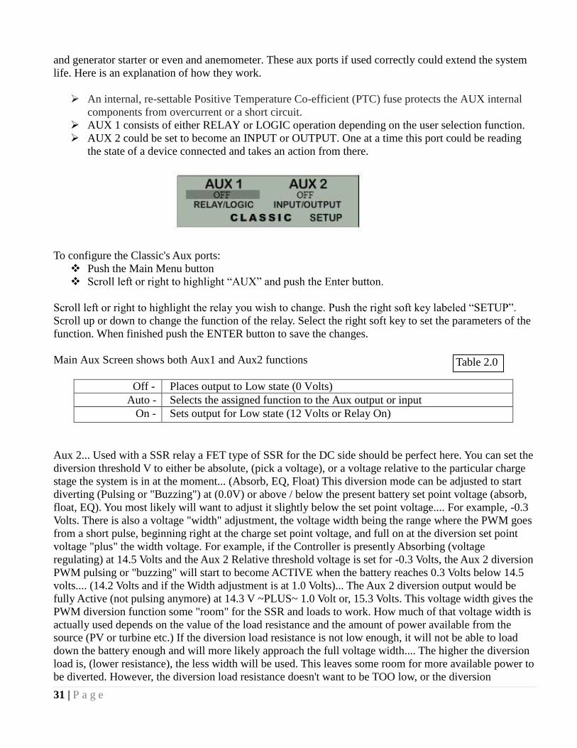
An internal, re-settable Positive Temperature Co-efficient (PTC) fuse protects the AUX internal
components from overcurrent or a short circuit.
AUX 1 consists of either RELAY or LOGIC operation depending on the user selection function.
AUX 2 could be set to become an INPUT or OUTPUT. One at a time this port could be reading
the state of a device connected and takes an action from there.
To configure the Classic's Aux ports:
Push the Main Menu button
Scroll left or right to highlight ―AUX‖ and push the Enter button.
Scroll left or right to highlight the relay you wish to change. Push the right soft key labeled ―SETUP‖.
Scroll up or down to change the function of the relay. Select the right soft key to set the parameters of the
function. When finished push the ENTER button to save the changes.
Main Aux Screen shows both Aux1 and Aux2 functions
Off - Places output to Low state (0 Volts)
Auto - Selects the assigned function to the Aux output or input
On - Sets output for Low state (12 Volts or Relay On)
Aux 2... Used with a SSR relay a FET type of SSR for the DC side should be perfect here. You can set the
diversion threshold V to either be absolute, (pick a voltage), or a voltage relative to the particular charge
stage the system is in at the moment... (Absorb, EQ, Float) This diversion mode can be adjusted to start
diverting (Pulsing or "Buzzing") at (0.0V) or above / below the present battery set point voltage (absorb,
float, EQ). You most likely will want to adjust it slightly below the set point voltage.... For example, -0.3
Volts. There is also a voltage "width" adjustment, the voltage width being the range where the PWM goes
from a short pulse, beginning right at the charge set point voltage, and full on at the diversion set point
voltage "plus" the width voltage. For example, if the Controller is presently Absorbing (voltage
regulating) at 14.5 Volts and the Aux 2 Relative threshold voltage is set for -0.3 Volts, the Aux 2 diversion
PWM pulsing or "buzzing" will start to become ACTIVE when the battery reaches 0.3 Volts below 14.5
volts.... (14.2 Volts and if the Width adjustment is at 1.0 Volts)... The Aux 2 diversion output would be
fully Active (not pulsing anymore) at 14.3 V ~PLUS~ 1.0 Volt or, 15.3 Volts. This voltage width gives the
PWM diversion function some "room" for the SSR and loads to work. How much of that voltage width is
actually used depends on the value of the load resistance and the amount of power available from the
source (PV or turbine etc.) If the diversion load resistance is not low enough, it will not be able to load
down the battery enough and will more likely approach the full voltage width.... The higher the diversion
load is, (lower resistance), the less width will be used. This leaves some room for more available power to
be diverted. However, the diversion load resistance doesn't want to be TOO low, or the diversion
Table 2.0

32 | P a g e
operation won't work quite as smoothly as it would if it has SOME room to move about.
Aux 1 diversion mode is similar to Aux 2 diversion mode except that it does not PWM, Pulse or buzz at
hundreds of Hz rate. Instead, Aux 1 diversion goes Active at or above the "High" voltage setting, after a
programmable "Delay" time, and goes Inactive when the voltage drops below the "Low" voltage setting
after a programmable "Hold" time. These Delay (or Attack) and Hold times are adjustable in 0.1 Volt
increments.
The Aux Relative Voltage adjustments are referenced to the temperature compensated Absorb, Float or
EQ voltage. In the Classic, the EQ regulation voltage can be chosen to be either battery temperature
compensated or not. This choice is picked in the Charge -- Temp-Comp menu.
In battery relative diversion mode, when either Aux outputs go "active", either solidly for Aux 1 or pulsed
for Aux 2, you can choose to keep the charge timers and counters running (or not) for the Absorb and EQ
stages so that the controller will go to Float when that charge stage is finished (its timer has expired). This
could be important, because the diversion might be holding the battery voltage below the desired set point
voltage for that charge stage. As long as the Relative diversion threshold voltage and absolute Absorb,
Float and EQ voltages (charge menu) are chosen with some degree of thought, using the diversion in
concert with the normal "raising the input power source voltage" method to regulate battery voltage, can
work very well for battery charging cycles. You might want to set the absolute a few tenths of a volt
higher than usual so that the diversion mode can be used to greater benefit. This will help to ensure that if
the diversion loads go away, the battery voltage won't go TOO much higher than desired and battery over-
gassing would be minimal. Using diversion in this way is what we call "Use It Or
Lose It" mode (Ui-Loi)... Just think of the song, "Louie-Louie".
For Relative diversion using Aux 1 or Aux 2, the default to keep the charge timers running will be
enabled.
Aux 1 and Aux 2 outputs can also be chosen to be "Active High" or "Active Low"... Active "High" is the
normal mode of operation and means that the Aux output will be at 0 Volts (ground) when Off and 12
Volts when On... Low, being 0 volts and High being 12 volts. Active High is shown in the Aux menus
with a "+" sign following the mode name and Active LOW mode with a "-" following the name. The
output voltage for a High is actually more like 14 or 15 Volts DC and can supply up to 200 milli-Amps of
current.
Aux 1 also has a (small) relay that can be jumpered into the circuit if an isolated switch is needed. This
might be used to start or stop a generator. Remember though that this is a very small relay with 1 Amp
rating and a series 1/2 Amp re-settable fuse in series with it to help protect its contacts.
Aux 1 Function
OUTPUT = Relay or 12V/0V Signal jumper selectable
Aux 1 has the relay so Diversion functions must operate slowly
DIVESION SLW+ Battery diversion using contact relay. Active high
DIVESION SLW- Battery diversion using contact relay. Active low
BAT DIV V REL+ Battery diversion relative to charge stage voltage. Active high
Table 2.1
33 | P a g e
BAT DIV V REL- Battery diversion relative to charge stage voltage. Active low
PV V TRIGGER + Input voltage controlled. Active high
PV V TRIGGER - Input voltage controlled. Active low
MANUAL ON-OFF Manual button on- off control.
TOGGLE TEST Output toggle once per second
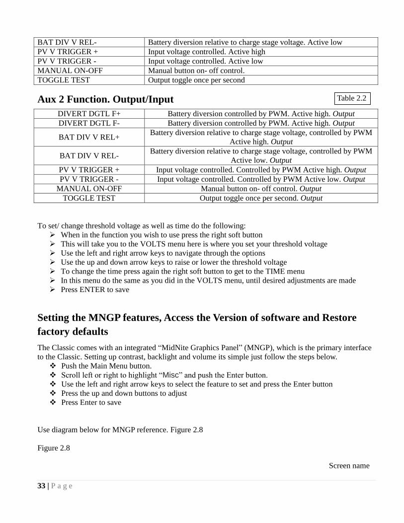
Aux 2 Function. Output/Input
DIVERT DGTL F+ Battery diversion controlled by PWM. Active high. Output
DIVERT DGTL F- Battery diversion controlled by PWM. Active high. Output
BAT DIV V REL+ Battery diversion relative to charge stage voltage, controlled by PWM
Active high. Output
BAT DIV V REL- Battery diversion relative to charge stage voltage, controlled by PWM
Active low. Output
PV V TRIGGER + Input voltage controlled. Controlled by PWM Active high. Output
PV V TRIGGER - Input voltage controlled. Controlled by PWM Active low. Output
MANUAL ON-OFF Manual button on- off control. Output
TOGGLE TEST Output toggle once per second. Output
To set/ change threshold voltage as well as time do the following:
When in the function you wish to use press the right soft button
This will take you to the VOLTS menu here is where you set your threshold voltage
Use the left and right arrow keys to navigate through the options
Use the up and down arrow keys to raise or lower the threshold voltage
To change the time press again the right soft button to get to the TIME menu
In this menu do the same as you did in the VOLTS menu, until desired adjustments are made
Press ENTER to save
Setting the MNGP features, Access the Version of software and Restore
factory defaults
The Classic comes with an integrated ―MidNite Graphics Panel‖ (MNGP), which is the primary interface
to the Classic. Setting up contrast, backlight and volume its simple just follow the steps below.
Push the Main Menu button.
Scroll left or right to highlight ―Misc‖ and push the Enter button.
Use the left and right arrow keys to select the feature to set and press the Enter button
Press the up and down buttons to adjust
Press Enter to save
Use diagram below for MNGP reference. Figure 2.8
Figure 2.8
Screen name
Table 2.2
34 | P a g e
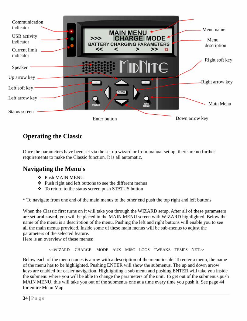
Operating the Classic
Once the parameters have been set via the set up wizard or from manual set up, there are no further
requirements to make the Classic function. It is all automatic.
Navigating the Menu's
Push MAIN MENU
Push right and left buttons to see the different menus
To return to the status screen push STATUS button
* To navigate from one end of the main menus to the other end push the top right and left buttons
When the Classic first turns on it will take you through the WIZARD setup. After all of these parameters
are set and saved, you will be placed in the MAIN MENU screen with WIZARD highlighted. Below the
name of the menu is a description of the menu. Pushing the left and right buttons will enable you to see
all the main menus provided. Inside some of these main menus will be sub-menus to adjust the
parameters of the selected feature.
Here is an overview of these menus:
<<WIZARD— CHARGE —MODE—AUX—MISC—LOGS—TWEAKS—TEMPS—NET>>
Below each of the menu names is a row with a description of the menu inside. To enter a menu, the name
of the menu has to be highlighted. Pushing ENTER will show the submenus. The up and down arrow
keys are enabled for easier navigation. Highlighting a sub menu and pushing ENTER will take you inside
the submenu where you will be able to change the parameters of the unit. To get out of the submenus push
MAIN MENU, this will take you out of the submenus one at a time every time you push it. See page 44
for entire Menu Map.
Down arrow key
Main Menu
Right arrow key
Right soft key
Up arrow key
Left soft key
Left arrow key
Status screen
Enter button
Current limit
indicator
Speaker
USB activity
indicator
Communication
indicator
Menu
description
Menu name

35 | P a g e
Viewing Other MidNite Products on the Display
The Classic is able to view other products or Classics connected to the network. For example: the
MidNite Solar Clipper. To view other products or Classics connected to the Classic network, go to the
Status screen and press the UP and DOWN arrows to scroll between the addresses of the different items.
The Classic is address 10 and labeled. CLASSIC
Connecting Classic to Two MNGPs/Network cable
The Classic can be controlled with two MNGPs at the same time. This will help when the Classic is in a
shop and there is a considerable distance between the Classic and the controlling point (office, inside
house, garage etc.). Instead of going to the Classic to check status or to change a setting, the user can run
a cable to the controlling point and see the Classic in a second MNGP. The cable is a six wire phone
cable. Connect one side of the extension cable to the jack in the Classic labeled SLAVE/OUT and the
other end to the second MNGP. Since the Classic transmits power and data signals through the phone
cable to the MNGP the length of the cable is limited to 100ft.
MidNite Solar only offers a 3ft as an optional
accessory. If you are making your own cable
be sure be sure to insert cable end all the way
into the phone terminal to get a good contact.
Use the phone crimping pliers to crimp both
ends of the cable.
We recommend using flat phone cable for extension, just
because it is easier to work with. Use the two pictures above as reference. Make sure the color and
position of the wires are as shown in the diagram below. Use terminal connector tab as reference.
Arc Fault
The Arc Fault Detector is a unique safety component included in every Classic, because safety is not an
option, the engineers at MidNite take action as the 2011 NEC code requires. The Classic is the first
charge controller in the world to successfully stop a series arc. The Classic can detect an arc in less than
100mSec. From low power arcing to devastating high power arcing, the Classic will detect and shut down
with an audible and visible alert to announce that there is a problem in the PV side of the system. When
an arc is detected the Classic has to be manually cleared.

36 | P a g e
Resetting the Arc Fault Detector after
detection has occurred: The First thing to
do is find and fix the actual arcing wire,
terminal, splice etc. The Classic needs to
be powered down completely for 15
seconds and then powered back up. Do
this by turning the DC source (PV, Wind
or hydro etc.) breaker off. Then turn off
the external battery breaker. Than simply
turn the 2 breakers back on starting with
the battery breaker.
The arc fault module has three adjustable parameters consisting of: MODE, TIME & SENSITVY
MODE: Is assigned as a 1 from factory default and it should stay that way unless instructed by MidNite
Solar.
TIME: This sets the length of the arc the Classic has to monitor before tripping the Arc fault detection.
This parameter is set to 4 from the factory.
SENSITIVITY: This parameter determines how sensitive the Arc fault detector will be 1 being the most
sensitive and 15 the least. This parameter is set to 10 from the factory.
If you experience nuisance tripping you can raise the sensitivity one digit at a time. Follow the
instructions below to make adjustments or disable Arc fault. As a last resort, you may disable Arc fault if
your system cannot work with the arc fault detector.
To change the parameters of the Arc Fault, follow the steps below:
Press Main Menu
Scroll to the right or left until TWEAKS is highlighted and press ENTER
In TWEAKS press the right soft key to get to the BITS menu
In BITS press the right soft key to get to ARC ADJ
In this menu use the left and right keys to select the feature to adjust
Use the up and down arrow keys to change the parameters
In order for the Classic to read the new settings you must power cycle the Classic. Do this by turning the
DC source (PV, Wind or hydro etc.) breaker off. Then turn off the external battery breaker. Than simply
turn the 2 breakers back on starting with the battery breaker.
View Faults and Warning's
The Classic has some helpful safety features including the GFP (Ground Fault Protection) and AFD (Arc
Fault Detector). When one or more faults are detected the Classic will stop outputting power and display
a fault message in the bottom right corner of the home screen (STATUS). To clear the fault refer to Page
19 and page 33; Arc Fault section.

37 | P a g e
View Logged Data
The Classic can log the power produced by your system. Shown in Total kilo Watt hours (kWh), you can
view daily logged data or accumulated throughout the life time of the Classic. Daily logged data is
displayed in the bottom left corner of the Status screen; the daily logged data will get reset to 0 kWh
every 24hrs. The total logged data is displayed in a menu screen called LOGS. Total logged data is an
accumulation of all of the power that has been produced by the system; this data cannot be reset back to 0
kWh. To view total kWh produced by you system:
Press Main Menu,
Scroll to LOGS and
Press the Enter button.
Uploading New Firmware to the Classic
There is also an Ethernet method for updating software in the Classic itself (Ethernet for MNGP Remote
coming soon). Up to this point the Classic cannot be updated using Windows 7®
Updating Classic Firmware (Windows XP)
Requirements:
PC with Windows XP
One available USB port
Internet Connection WARNING ! The Classic's USB port is NOT isolated from battery negative. This is typically only an issue on positive ground systems or systems with a tripped ground fault protection device. Care must be taken that a computer con-nected to the Classic's USB port is either isolated from ground and the Classic's negative or that the computer's USB negative is common with the Classic's negative and ground.
1. To retrieve the firmware, go to www.midnitesolar.com, then click on the link labeled ―Firmware‖ in the top
menu bar of the web site.
38 | P a g e
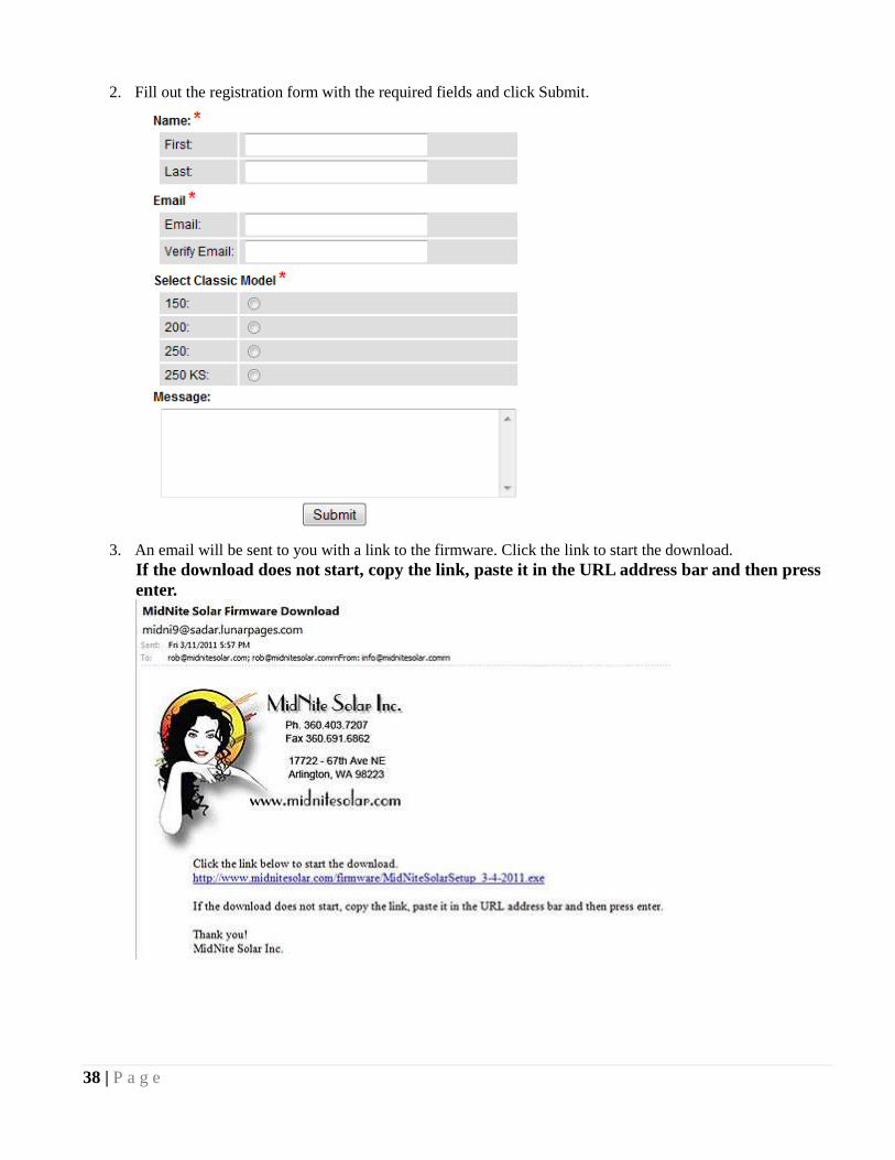
2. Fill out the registration form with the required fields and click Submit.
3. An email will be sent to you with a link to the firmware. Click the link to start the download.
If the download does not start, copy the link, paste it in the URL address bar and then press
enter.
39 | P a g e
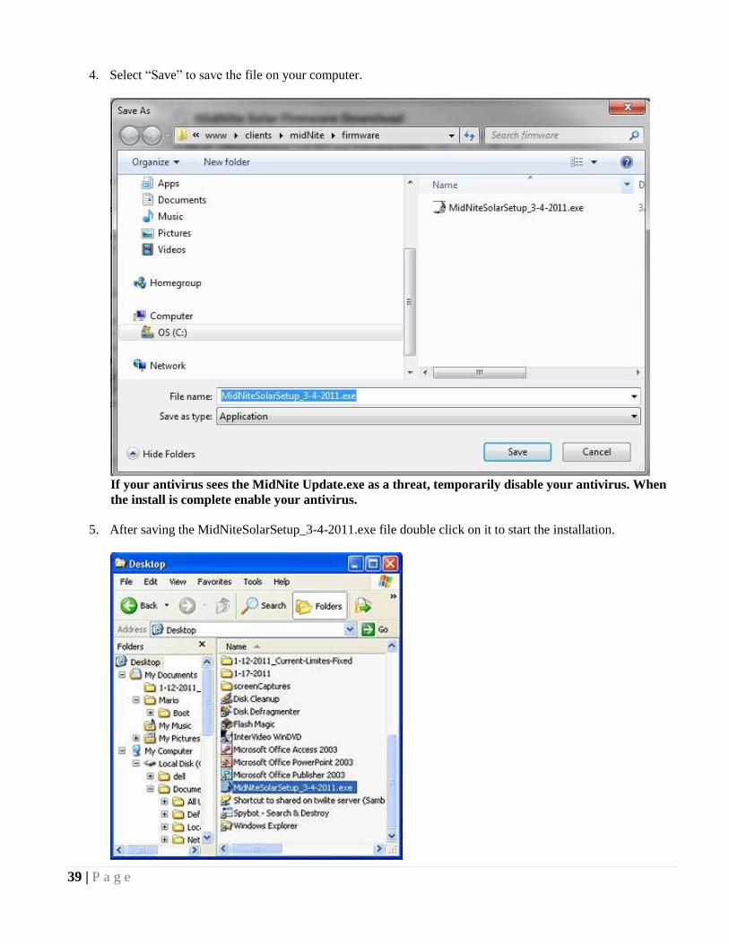
4. Select ―Save‖ to save the file on your computer.
If your antivirus sees the MidNite Update.exe as a threat, temporarily disable your antivirus. When
the install is complete enable your antivirus.
5. After saving the MidNiteSolarSetup_3-4-2011.exe file double click on it to start the installation.

40 | P a g e
6. The Software License Agreement dialog box will appear. Click ―Yes‖ to except the terms.
7. In the ―Select Program Folder‖ dialog box make sure that MidNiteSolar is in the Program Folder field, and
then click ―Next‖.
41 | P a g e
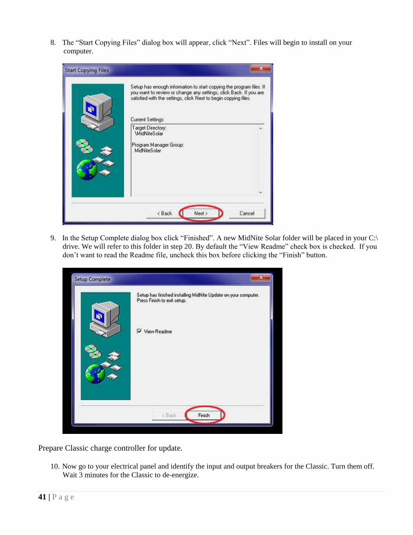
8. The ―Start Copying Files‖ dialog box will appear, click ―Next‖. Files will begin to install on your
computer.
9. In the Setup Complete dialog box click ―Finished‖. A new MidNite Solar folder will be placed in your C:\
drive. We will refer to this folder in step 20. By default the ―View Readme‖ check box is checked. If you
don‘t want to read the Readme file, uncheck this box before clicking the ―Finish‖ button.
Prepare Classic charge controller for update.
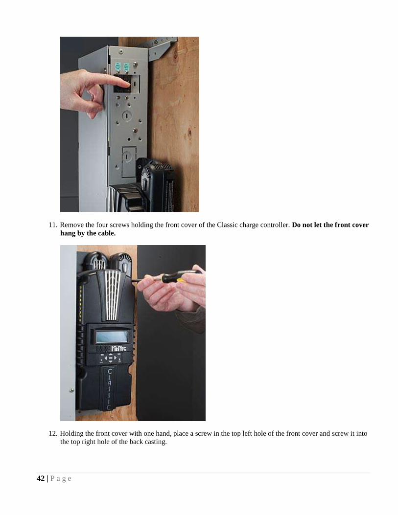
10. Now go to your electrical panel and identify the input and output breakers for the Classic. Turn them off.
Wait 3 minutes for the Classic to de-energize.
42 | P a g e
11. Remove the four screws holding the front cover of the Classic charge controller. Do not let the front cover
hang by the cable.
12. Holding the front cover with one hand, place a screw in the top left hole of the front cover and screw it into
the top right hole of the back casting.

43 | P a g e
13. Use the provided USB cable to connect the Classic to the PC. The smaller terminal connects to the USB
port on the Classic. The USB port is located on the right side of the Ethernet Jack in the lower part of the
Classic.

44 | P a g e
14. Connect the other end of the USB cable to an available port of the PC.
Install USB Classic driver
15. Go back to the electrical panel and turn on the battery breaker to the Classic.

45 | P a g e
16. The LED above the USB port on the Classic will light up and stay on.
17. The computer will prompt with a ―Found New Hardware‖ pop-up. Select ―Not at this time‖ and
press ―Next‖.

46 | P a g e
18. A ―New Found Hardware Wizard‖ dialog box will appear. Select ―Install from a list or specific lo-
cation (Advanced)‖ and click ―Next‖.
19. Select ―Search for the best driver in this location‖. Check the ―Include this location in the search‖
checkbox and then click ―Browse‖.
20. Browse to the MidNite Solar folder located on the C:\\ drive and click OK.
47 | P a g e
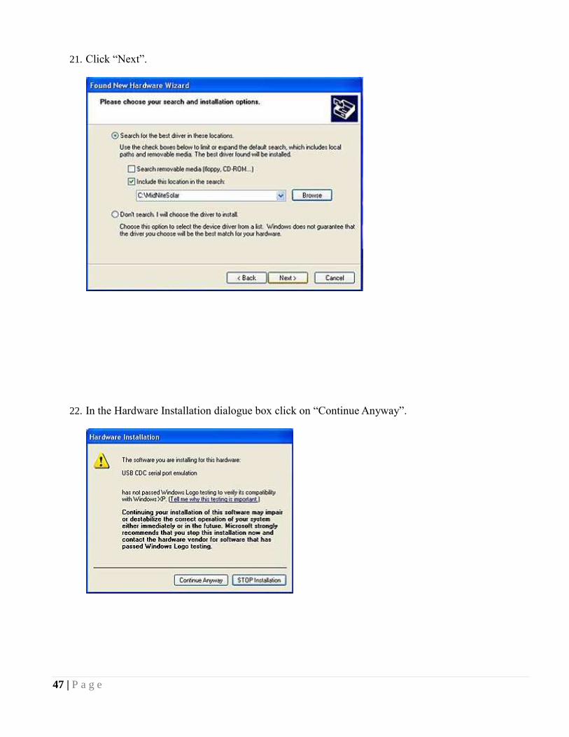
21. Click ―Next‖.
22. In the Hardware Installation dialogue box click on ―Continue Anyway‖.
48 | P a g e
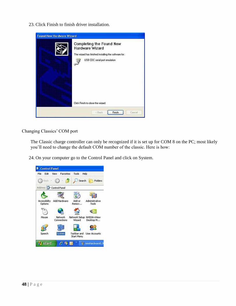
23. Click Finish to finish driver installation.
Changing Classics‘ COM port
The Classic charge controller can only be recognized if it is set up for COM 8 on the PC; most likely
you‘ll need to change the default COM number of the classic. Here is how:
24. On your computer go to the Control Panel and click on System.
49 | P a g e
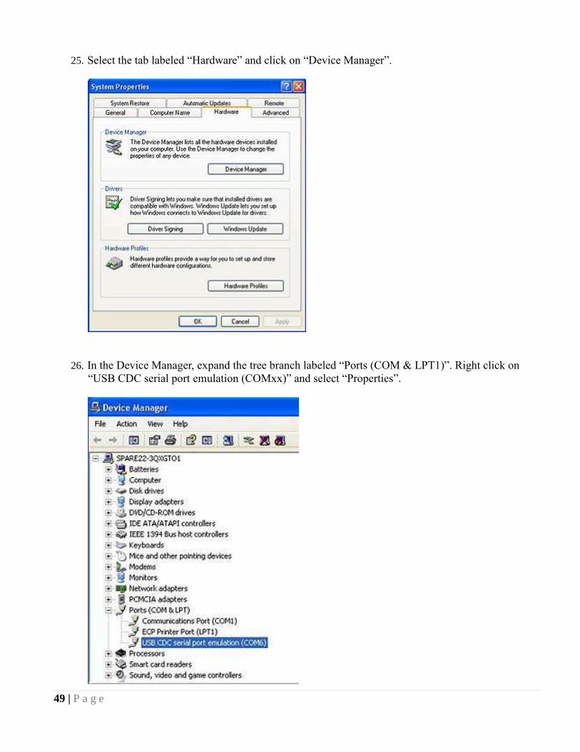
25. Select the tab labeled ―Hardware‖ and click on ―Device Manager‖.
26. In the Device Manager, expand the tree branch labeled ―Ports (COM & LPT1)‖. Right click on
―USB CDC serial port emulation (COMxx)‖ and select ―Properties‖.
50 | P a g e
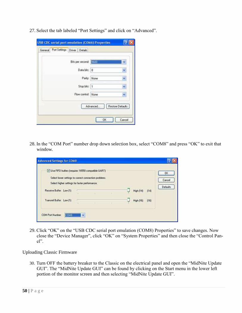
27. Select the tab labeled ―Port Settings‖ and click on ―Advanced‖.
28. In the ―COM Port‖ number drop down selection box, select ―COM8‖ and press ―OK‖ to exit that
window.
29. Click ―OK‖ on the ―USB CDC serial port emulation (COM8) Properties‖ to save changes. Now
close the ―Device Manager‖, click ―OK‖ on ―System Properties‖ and then close the ―Control Pan-
el‖.
Uploading Classic Firmware
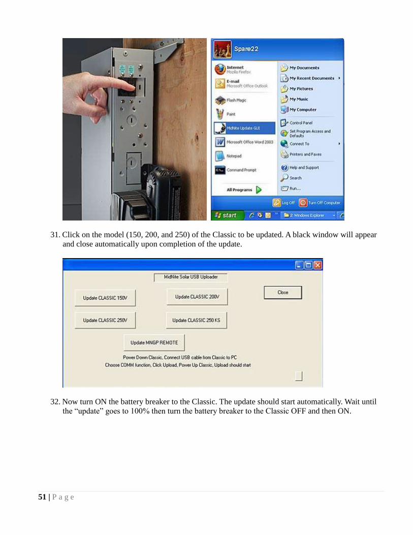
30. Turn OFF the battery breaker to the Classic on the electrical panel and open the ―MidNite Update
GUI‖. The ―MidNite Update GUI‖ can be found by clicking on the Start menu in the lower left
portion of the monitor screen and then selecting ―MidNite Update GUI‖.
51 | P a g e
31. Click on the model (150, 200, and 250) of the Classic to be updated. A black window will appear
and close automatically upon completion of the update.
32. Now turn ON the battery breaker to the Classic. The update should start automatically. Wait until
the ―update‖ goes to 100% then turn the battery breaker to the Classic OFF and then ON.

52 | P a g e
Turning the breaker off and on resets the Classic so the new settings take effect.
33. If MNGP (MidNite Graphics Panel) needs to be updated as well, turn OFF the battery breaker to
the Classic. Click on the ―MNGP‖ button on the ―MidNite Update GUI‖ then turn ON the breaker.
34. Wait until the uploading percentage reaches 100% and then turn the battery breaker to the classic
OFF and then ON. Turning the breaker off and on resets the Classic so the new settings to
take effect. This now completes the firmware installation. The battery settings, saved graphs and
LCD settings on the Classic will remain the same.
Beware: If the Classic has been updated with a different model of Classic firmware than the factory
default, the charge controller will display a “WRONG CODE” message on the bottom right corner
of the Status screen and it will not turn ON.
53 | P a g e
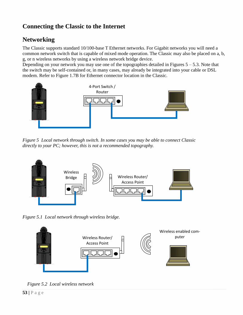
Connecting the Classic to the Internet
Networking
The Classic supports standard 10/100-base T Ethernet networks. For Gigabit networks you will need a
common network switch that is capable of mixed mode operation. The Classic may also be placed on a, b,
g, or n wireless networks by using a wireless network bridge device.
Depending on your network you may use one of the topographies detailed in Figures 5 – 5.3. Note that
the switch may be self-contained or, in many cases, may already be integrated into your cable or DSL
modem. Refer to Figure 1.7B for Ethernet connector location in the Classic.
4-Port Switch / Router
Figure 5 Local network through switch. In some cases you may be able to connect Classic
directly to your PC; however, this is not a recommended topography.
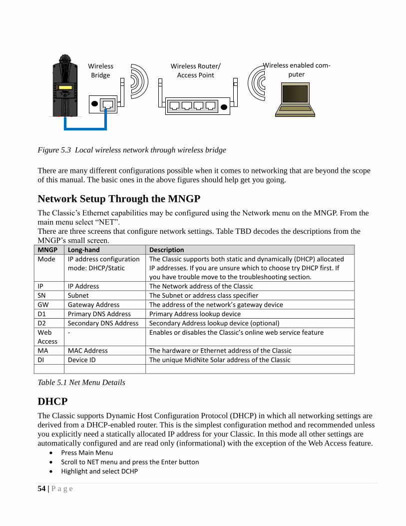
Wireless Router/ Access Point
Wireless Bridge
Figure 5.1 Local network through wireless bridge.
Wireless Router/ Access Point
Wireless enabled com-puter
Figure 5.2 Local wireless network
54 | P a g e
There are many different configurations possible when it comes to networking that are beyond the scope
of this manual. The basic ones in the above figures should help get you going.
Network Setup Through the MNGP
The Classic‘s Ethernet capabilities may be configured using the Network menu on the MNGP. From the
main menu select ―NET‖.
There are three screens that configure network settings. Table TBD decodes the descriptions from the
MNGP‘s small screen.
MNGP Long-hand Description
Mode IP address configuration mode: DHCP/Static
The Classic supports both static and dynamically (DHCP) allocated IP addresses. If you are unsure which to choose try DHCP first. If you have trouble move to the troubleshooting section.
IP IP Address The Network address of the Classic
SN Subnet The Subnet or address class specifier
GW Gateway Address The address of the network’s gateway device
D1 Primary DNS Address Primary Address lookup device
D2 Secondary DNS Address Secondary Address lookup device (optional)
Web Access
- Enables or disables the Classic’s online web service feature
MA MAC Address The hardware or Ethernet address of the Classic
DI Device ID The unique MidNite Solar address of the Classic
Table 5.1 Net Menu Details
DHCP
The Classic supports Dynamic Host Configuration Protocol (DHCP) in which all networking settings are
derived from a DHCP-enabled router. This is the simplest configuration method and recommended unless
you explicitly need a statically allocated IP address for your Classic. In this mode all other settings are
automatically configured and are read only (informational) with the exception of the Web Access feature.
Press Main Menu
Scroll to NET menu and press the Enter button
Highlight and select DCHP
Wireless enabled com-puter
Wireless Router/ Access Point
Wireless Bridge
Figure 5.3 Local wireless network through wireless bridge

55 | P a g e
Please note that the Classic‘s DHCP protocol implementation usually takes a few seconds up to a minute
to update the network settings. If the network settings do not update within a minute, please consult the
troubleshooting section.
Static IP
The Classic supports static IP address allocation. In this mode you can assign the Classic a specific IP
address. This lets you set up things like port forwarding from your router or for networks with static IP
allocations.
Press Main Menu
Scroll to NET menu and press the Enter button
Highlight and select STATIC
Using the left and right keys, navigate to the settings to change and use the up and down arrows to adjust the desired fields.
Press the COMMIT softkey at any time to commit the settings to the Classic’s Flash memory.
Please note that static settings span two menu screens. You may use the soft keys to navigate between the
two menus. Pressing the ENTER key in either menu saves all settings to Flash memory.
For convenience when you manually set the device‘s IP address the Gateway and Primary DNS addresses
follow the change. See the following sections for details on each of these fields.
IP Address
This is the local network address of your Classic. It usually takes the form ―192.169.0/1.x‖ or ―10.0.0.x‖
depending on your networking equipment. You must be careful when selecting this address. If it does not
match your network subnet then the classic will not be able to communicate with the network. If it is the
same as another device on the network then collisions will occur causing both devices to act erratically.
Check your router settings or ask your network administrator which local address to use. Also refer to the
troubleshooting section for tips.
Subnet
This refers to the class of local network you are using. This depends on your network hardware but most
users should use ―255.255.255.0‖ for this field.
Gateway
This is the address of your router or modem – the device which is connected directly to the Internet
proper. It will usually take the form 192.168.0/1.1 or 10.0.0.1 depending on your network configuration
and hardware. Check your router settings or ask your network administrator which local address to use.
Also refer to the troubleshooting section for tips.
DNS 1 & 2
The DNS is the means by which human-readable internet addresses are resolved to actual IP addresses on
the network. These values can usually be set identically to the gateway address depending on your
network hardware. If your ISP provides you with specific DNS servers then use those addresses in these
fields instead.
Example 1: Your gateway is a DSL modem with address 192.168.1.1. If your ISP has not given you
explicit DNS servers to use then set the D1 field to 192.168.1.1. D2 can be ignored.

56 | P a g e
Example 2: Your gateway is a cable modem with address 10.0.0.1. Your ISP has specified primary and
secondary DNS server addresses of 11.22.33.44 and 11.22.33.55, respectively. Set the D1 address to
11.22.33.44 and the D2 address to 11.22.33.55.
Web Access
MidNite Solar offers a free web service with which you can access your Classic from a web page from
anywhere in the world simply by pointing your favorite web browser to
http://www.mymidnite.com
See the web section further on for instructions on how to create an account and use the web-based system.
All communications between the Classic and MidNite Solar‘s server are encrypted using a strong session-
based algorithm. To respect your privacy, however, it is required that you manually enable this feature if
you‘d like to use it.
In order to enable the web access feature:
Press Main Menu
Scroll to NET menu and press the Enter button
using the soft keys, navigate to the ADVANCED menu (NET→NEXT→ADVANCED)
The Web Access option should be highlighted.
Use the up/down keys to now enable or disable the feature.
Note that the Web Access selection indicates the current setting of the feature: i.e. ENABLED means the
feature is currently in operation.
Note also that you will need the values MA and DI handy in order to create an account on the MidNite
Solar web site. This unique number pair identifies your particular classic to our server and helps to
prevent malicious users from trying to access your Classic. The DI or Device Id is different than your
Unit‘s Serial Number.
Local Network
Note that your classic identifies itself by name to DHCP-enabled routers as ―Classic‖. There is facility to
change the name of a given classic via the local and web-based interfaces as well as using third-party
MODBUS software packages.
Advanced
The Classic advertises its address every 10 seconds using the UDP protocol on port (TBD). Advanced
users and programmers may use this feature to identify Classics on their network.
MODBUS (Preliminary)
DISCLAIMER
There is not a convention on the write-ability of registers. You may write to any register in the system
including registers THAT MAY DAMAGE OR DESTROY your Classic and attached equipment like
battery banks. Please make sure that you understand what you are doing before attempting to change any
settings (like battery voltage) using the raw MODBUS interface. MidNite Solar cannot take
responsibility for any damage to your Classic in the event of misconfiguration.

57 | P a g e
Registers and bits marked RESERVED are not necessarily unimplemented. Great care must be taken not
to overwrite these registers or bits to ensure proper operation of the Classic.
Wherever possible we have tried to indicate settings that may have an adverse effect on your system if set
incorrectly.
If you need to configure your system, please consider using the MNGP‘s built in configuration wizard
which will step you through the process.
Conventions:
Register units are expressed using formulas to try to reduce the ambiguity surrounding converting from
the raw bus formats and human-readable values. Due to the nature of the Classic‘s operation, there is not
a uniform convention as far as data endianness so you may find some classes of values that follow a Most
Significant Byte (MSB) first convention and others that use the Least Significant Byte (LSB) first
convention.
Bits are numbered from 0-15 in the little-endian or LSB-0 notation. That is, the least significant bit is
indexed by 0.
For Example, the number 43,981 is 0xABCD in hex is represented in binary as 1010101111001101.
The bit ordering is as shown in the following table: 15 14 13 12 11 10 9 8 7 6 5 4 3 2 1 0
1 0 1 0 1 0 1 1 1 1 0 0 1 1 0 1
So that the binary digit indexed by (0) is 1. (1) is 0, (6) is 1, and (10) is 0.
MODBUS registers are 16-bit (2-octet/byte) in size. When using values from the map to indicate
conversion formulas the following convention is used to access different octets:
Note that when talking about bytes or octets, it is more convenient to describe them in hexadecimal (base
16) form than in decimal. Some values are expressed in bytes as it is a more compact way of dealing with
certain classes of numbers (IP addresses, for example). We use the ‗C‘ convention of referring to
hexadecimal numbers by prefixing them with ‗0x‘. So the decimal value 10 is represented by the
hexadecimal value 0x0A.
A note on Read/Write: The Classic MODBUS does not strictly enforce the Read/Write accessibility of
some registers. It is possible to write to some registers marked Read Only. This will usually have no effect
on Classic operation, but in some cases you may corrupt a register from which you wanted to read data. In
some cases the registers are reset internally as new values. Additionally, some counters are accessible
directly. For example, the AbsorbTime (4139) timer is a ―suggested‖ read only register; however, if your
MODBUS application has reason to reset or adjust this register, there is nothing to prevent you from
changing it however you please. Don‘t be surprised if your batteries pop in and out of Absorb stage
unexpectedly, though!
Operators:
Indexing
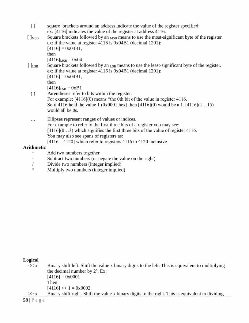
58 | P a g e
[ ] square brackets around an address indicate the value of the register specified:
ex: [4116] indicates the value of the register at address 4116.
[ ]MSB Square brackets followed by an MSB means to use the most-significant byte of the register.
ex: if the value at register 4116 is 0x04B1 (decimal 1201):
[4116] = 0x04B1,
then
[4116]MSB = 0x04
[ ]LSB Square brackets followed by an LSB means to use the least-significant byte of the register.
ex: if the value at register 4116 is 0x04B1 (decimal 1201):
[4116] = 0x04B1,
then
[4116]LSB = 0xB1
( ) Parentheses refer to bits within the register.
For example: [4116](0) means ―the 0th bit of the value in register 4116.
So if 4116 held the value 1 (0x0001 hex) then [4116](0) would be a 1. [4116](1…15)
would all be 0s.
… Ellipses represent ranges of values or indices.
For example to refer to the first three bits of a register you may see:
[4116](0…3) which signifies the first three bits of the value of register 4116.
You may also see spans of registers as:
[4116…4120] which refer to registers 4116 to 4120 inclusive.
Arithmetic
+ Add two numbers together
- Subtract two numbers (or negate the value on the right)
/ Divide two numbers (integer implied)
* Multiply two numbers (integer implied)
Logical
<< x Binary shift left. Shift the value x binary digits to the left. This is equivalent to multiplying
the decimal number by 2x. Ex:
[4116] = 0x0001
Then
[4116] << 1 = 0x0002.
>> x Binary shift right. Shift the value x binary digits to the right. This is equivalent to dividing
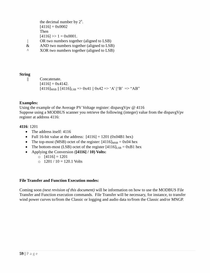
59 | P a g e
the decimal number by 2x.
[4116] = 0x0002
Then
[4116] >> 1 = 0x0001.
| OR two numbers together (aligned to LSB)
& AND two numbers together (aligned to LSB)
^ XOR two numbers together (aligned to LSB)
String
|| Concatenate.
[4116] = 0x4142.
[4116]MSB || [4116]LSB => 0x41 || 0x42 => ‗A‘ ||‗B‘ => ―AB‖
Examples:
Using the example of the Average PV Voltage register: dispavgVpv @ 4116
Suppose using a MODBUS scanner you retrieve the following (integer) value from the dispavgVpv
register at address 4116:
4116: 1201
The address itself: 4116
Full 16-bit value at the address: [4116] = 1201 (0x04B1 hex)
The top-most (MSB) octet of the register: [4116]MSB = 0x04 hex
The bottom-most (LSB) octet of the register [4116]LSB = 0xB1 hex
Applying the Conversion ([4116] / 10) Volts:
o [4116] = 1201
o 1201 / 10 = 120.1 Volts
File Transfer and Function Execution modes:
Coming soon (next revision of this document) will be information on how to use the MODBUS File
Transfer and Function execution commands. File Transfer will be necessary, for instance, to transfer
wind power curves to/from the Classic or logging and audio data to/from the Classic and/or MNGP.
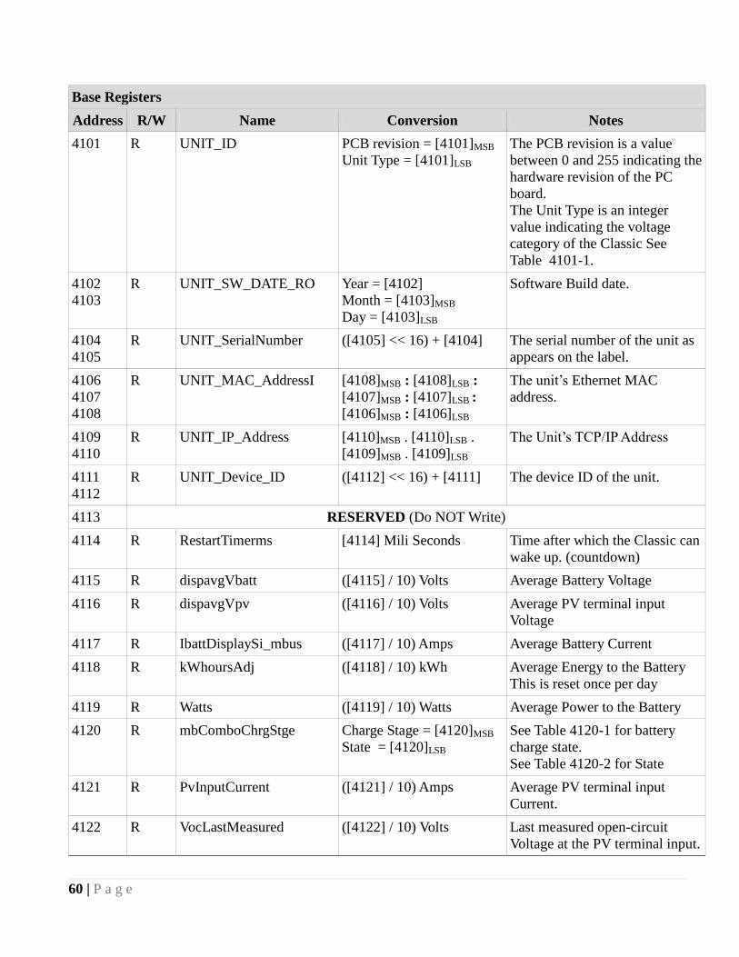
60 | P a g e
Base Registers
Address R/W Name Conversion Notes
4101 R UNIT_ID PCB revision = [4101]MSB
Unit Type = [4101]LSB
The PCB revision is a value
between 0 and 255 indicating the
hardware revision of the PC
board.
The Unit Type is an integer
value indicating the voltage
category of the Classic See
Table 4101-1.
4102
4103
R UNIT_SW_DATE_RO
Year = [4102]
Month = [4103]MSB
Day = [4103]LSB
Software Build date.
4104
4105
R UNIT_SerialNumber
([4105] << 16) + [4104] The serial number of the unit as
appears on the label.
4106
4107
4108
R UNIT_MAC_AddressI [4108]MSB : [4108]LSB :
[4107]MSB : [4107]LSB :
[4106]MSB : [4106]LSB
The unit‘s Ethernet MAC
address.
4109
4110
R UNIT_IP_Address [4110]MSB . [4110]LSB .
[4109]MSB . [4109]LSB
The Unit‘s TCP/IP Address
4111
4112
R UNIT_Device_ID ([4112] << 16) + [4111] The device ID of the unit.
4113 RESERVED (Do NOT Write)
4114 R RestartTimerms [4114] Mili Seconds Time after which the Classic can
wake up. (countdown)
4115 R dispavgVbatt ([4115] / 10) Volts Average Battery Voltage
4116 R dispavgVpv ([4116] / 10) Volts Average PV terminal input
Voltage
4117 R IbattDisplaySi_mbus ([4117] / 10) Amps Average Battery Current
4118 R kWhoursAdj ([4118] / 10) kWh Average Energy to the Battery
This is reset once per day
4119 R Watts ([4119] / 10) Watts Average Power to the Battery
4120 R mbComboChrgStge Charge Stage = [4120]MSB
State = [4120]LSB
See Table 4120-1 for battery
charge state.
See Table 4120-2 for State
4121 R PvInputCurrent ([4121] / 10) Amps Average PV terminal input
Current.
4122 R VocLastMeasured ([4122] / 10) Volts Last measured open-circuit
Voltage at the PV terminal input.
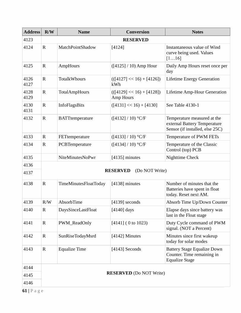
61 | P a g e
Address R/W Name Conversion Notes
4123 RESERVED
4124 R MatchPointShadow [4124] Instantaneous value of Wind
curve being used. Values
[1…16]
4125 R AmpHours ([4125] / 10) Amp Hour Daily Amp Hours reset once per
day
4126
4127
R TotalkWhours (([4127] << 16) + [4126])
kWh
Lifetime Energy Generation
4128
4129
R TotalAmpHours (([4129] << 16) + [4128])
Amp Hours
Lifetime Amp-Hour Generation
4130
4131
R InfoFlagsBits ([4131] << 16) + [4130] See Table 4130-1
4132 R BATTtemperature ([4132] / 10) °C/F Temperature measured at the
external Battery Temperature
Sensor (if installed, else 25C)
4133 R FETtemperature ([4133] / 10) °C/F Temperature of PWM FETs
4134 R PCBTemperature ([4134] / 10) °C/F Temperature of the Classic
Control (top) PCB
4135 NiteMinutesNoPwr [4135] minutes Nighttime Check
4136
RESERVED (Do NOT Write)
4137
4138 R TimeMinutesFloatToday [4138] minutes Number of minutes that the
Batteries have spent in float
today. Reset next AM.
4139 R/W AbsorbTime [4139] seconds Absorb Time Up/Down Counter
4140 R DaysSinceLastFloat [4140] days Elapse days since battery was
last in the Float stage
4141 R PWM_ReadOnly [4141] ( 0 to 1023) Duty Cycle command of PWM
signal. (NOT a Percent)
4142 R SunRiseTodayMsrd [4142] Minutes Minutes since first wakeup
today for solar modes
4143 R Equalize Time [4143] Seconds Battery Stage Equalize Down
Counter. Time remaining in
Equalize Stage
4144
RESERVED (Do NOT Write) 4145
4146
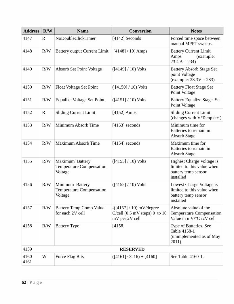
62 | P a g e
Address R/W Name Conversion Notes
4147 R NoDoubleClickTimer [4142] Seconds Forced time space between
manual MPPT sweeps.
4148 R/W Battery output Current Limit [4148] / 10) Amps Battery Current Limit
Amps (example:
23.4 A = 234)
4149 R/W Absorb Set Point Voltage ([4149] / 10) Volts Battery Absorb Stage Set
point Voltage
(example: 28.3V = 283)
4150 R/W Float Voltage Set Point ( [4150] / 10) Volts Battery Float Stage Set
Point Voltage
4151 R/W Equalize Voltage Set Point ([4151] / 10) Volts Battery Equalize Stage Set
Point Voltage
4152 R Sliding Current Limit [4152] Amps Sliding Current Limit
(changes with V/Temp etc.)
4153 R/W Minimum Absorb Time [4153] seconds Minimum time for
Batteries to remain in
Absorb Stage.
4154 R/W Maximum Absorb Time [4154] seconds Maximum time for
Batteries to remain in
Absorb Stage.
4155 R/W Maximum Battery
Temperature Compensation
Voltage
([4155] / 10) Volts Highest Charge Voltage is
limited to this value when
battery temp sensor
installed
4156 R/W Minimum Battery
Temperature Compensation
Voltage
([4155] / 10) Volts Lowest Charge Voltage is
limited to this value when
battery temp sensor
installed
4157 R/W Battery Temp Comp Value
for each 2V cell
-([4157] / 10) mV/degree
C/cell (0.5 mV steps) 0 to 10
mV per 2V cell
Absolute value of the
Temperature Compensation
Value in mV/°C /2V cell
4158 R/W Battery Type [4158] Type of Batteries. See
Table 4158-1
(unimplemented as of May
2011)
4159 RESERVED
4160
4161
W Force Flag Bits ([4161] << 16) + [4160] See Table 4160-1.
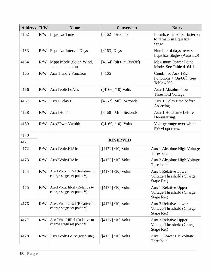
63 | P a g e
Address R/W Name Conversion Notes
4162 R/W Equalize Time [4162] Seconds Initialize Time for Batteries
to remain in Equalize
Stage.
4163 R/W Equalize Interval Days [4163] Days Number of days between
Equalize Stages (Auto EQ)
4164 R/W Mppt Mode (Solar, Wind,
…………… etc)
[4164] (bit 0 = On/Off) Maximum Power Point
Mode. See Table 4164-1.
4165 R/W Aux 1 and 2 Function [4165] Combined Aux 1&2
Functions + On/Off. See
Table 4208
4166 R/W Aux1VoltsLoAbs ([4166] /10) Volts Aux 1 Absolute Low
Threshold Voltage
4167 R/W Aux1DelayT [4167] Milli Seconds Aux 1 Delay time before
Asserting.
4168 R/W Aux1HoldT [4168] Milli Seconds Aux 1 Hold time before
De-asserting.
4169 R/W Aux2PwmVwidth ([4169] /10) Volts Voltage range over which
PWM operates.
4170
RESERVED 4171
4172 R/W Aux1VoltsHiAbs ([4172] /10) Volts Aux 1 Absolute High Voltage
Threshold
4173 R/W Aux2VoltsHiAbs ([4173] /10) Volts Aux 2 Absolute High Voltage
Threshold
4174 R/W Aux1VoltsLoRel (Relative to
charge stage set point V) ([4174] /10) Volts Aux 1 Relative Lower
Voltage Threshold (Charge
Stage Rel)
4175 R/W Aux1VoltsHiRel (Relative to
charge stage set point V) ([4175] /10) Volts Aux 1 Relative Upper
Voltage Threshold (Charge
Stage Rel)
4176 R/W Aux2VoltsLoRel (Relative to
charge stage set point V) ([4176] /10) Volts Aux 2 Relative Lower
Voltage Threshold (Charge
Stage Rel)
4177 R/W Aux2VoltsHiRel (Relative to
charge stage set point V) ([4177] /10) Volts Aux 2 Relative Upper
Voltage Threshold (Charge
Stage Rel)
4178 R/W Aux1VoltsLoPv (absolute) ([4178] /10) Volts Aux 1 Lower PV Voltage
Threshold

64 | P a g e
Address R/W Name Conversion Notes
4179 R/W Aux1VoltsHiPv (absolute) ([4179] /10) Volts Aux 1 High PV Voltage
Threshold
4180 RESERVED (Do NOT Write)
4181 R/W Aux2VoltsHiPv (absolute) ([4181] /10) Volts Aux 2 High PV Voltage
Threshold
4182 RESERVED (Do NOT Write)
4183 R/W ArcFaultSenstvty Time = [4183]
Sense = [4183]
Arc Fault Protection
sensitivity response
adjustments
4184
RESERVED (Do NOT Write) 4185
4186
4187 R/W Enable Flags bits [4187] See Table 4187-1
4188 R/W RESERVED [4188] RESERVED(Do NOT
Write)
4189 R/W Vbatt_Offset ([4189] /10) Battery Voltage Offset Tweak
(Range Limited) (Signed)
4190 R/W Vpv_Offset ([4190] /10) Input Voltage Offset Tweak
(Range Limited) (Signed)
4191 R VpvTargetRd ([4191] /10) Volts Input Target (V regulation)
Voltage (Usually Vmpp)
4192
RESERVED (Do NOT Write)
4193
4194
4195
4196
4197 R/W LgcySweepIntervalSecs [4197] Seconds Legacy P&O, Hydro, Solar,
U-Set Sweep Interval,
Seconds
(Forcing Sweep resets timer)
4198 R/W MinSwpVocPercentage ([4198] / 100) % Minimum sweep as a
percentage of Voc (Unused)
4199 R/W MaxSwpVocPercentage ([4199] / 100)% Maximum sweep as a
percentage of Voc (Unused)
4200 R/W SweepDepth [4200] Watts % Percent of last Mpp Watts

65 | P a g e
4201 RESERVED (Do NOT Write)
Address R/W Name Conversion Notes
4202 R/W ClipperCmdVolts ([4202] /10) Volts Variable Voltage command to
Clipper or Aux in Clipper mode
4203 R/W WindNumberOfPoles [4203] poles Number of turbine alternator
poles (for RPM Calc)
4204 R/W MppPercentVoc [4204] 00 to 100 % % of Voc for U-Set mode
4205 R/W WindTableToUse [4205] FUTURE power curve select
4206 R/W WindTableLearn [4206] FUTURE Wind Learn usage
4207 R/W LEDmode [4207] See Table 4207-1
4208
4209
RESERVED
4210
4211
4212
4213
R/W ID name [4210]MSB || [4210]LSB ||
[4210]MSB || [4210]LSB ||
[4210]MSB || [4210]LSB ||
[4210]MSB || [4210]LSB || (End
with 00 if less than 8
characters)
Unit Name. DHCP and
MODBUS name. 8 character
maximum ASCII. Takes
place of MODBUS address
in MNGP display if present
(this needs some work)
4214
4215
W CTIME0 ([4215] << 16) + [4214]
(possibly atomic op)
Consolidated Time Registers
SEE Table 4214-1
4216
4217
W CTIME1 ([4217] << 16) + [4216]
(possibly atomic op)
Consolidated Time Registers
SEE Table 4216-1
4218 W CTIME2 [4218] Consolidated Time Registers
SEE Table 4218-1
4219 R/W BaudRateStopStartEtc [4219] Baud rate, bps
(Not implemented as of May
2011)
MODBUS Serial Baud rate.
Note that writing this register
will immediately change the
target unit‘s serial baud rate
which may result in
communication problems
with other units in the system
including the unit‘s MNGP.
4220 R/W RemoteMenuMode [4220] Present Remote Menu sent
from MNGP
4221 R/W RemoteButtons [4221] Remote Buttons pressed from
MNGP
4222 R/W VbatOvrshootSenstvty [4222] Overshoot Sensitivity (not
implemented)
4223 R/W RESERVED [4223] RESERVED (Do NOT
Write)
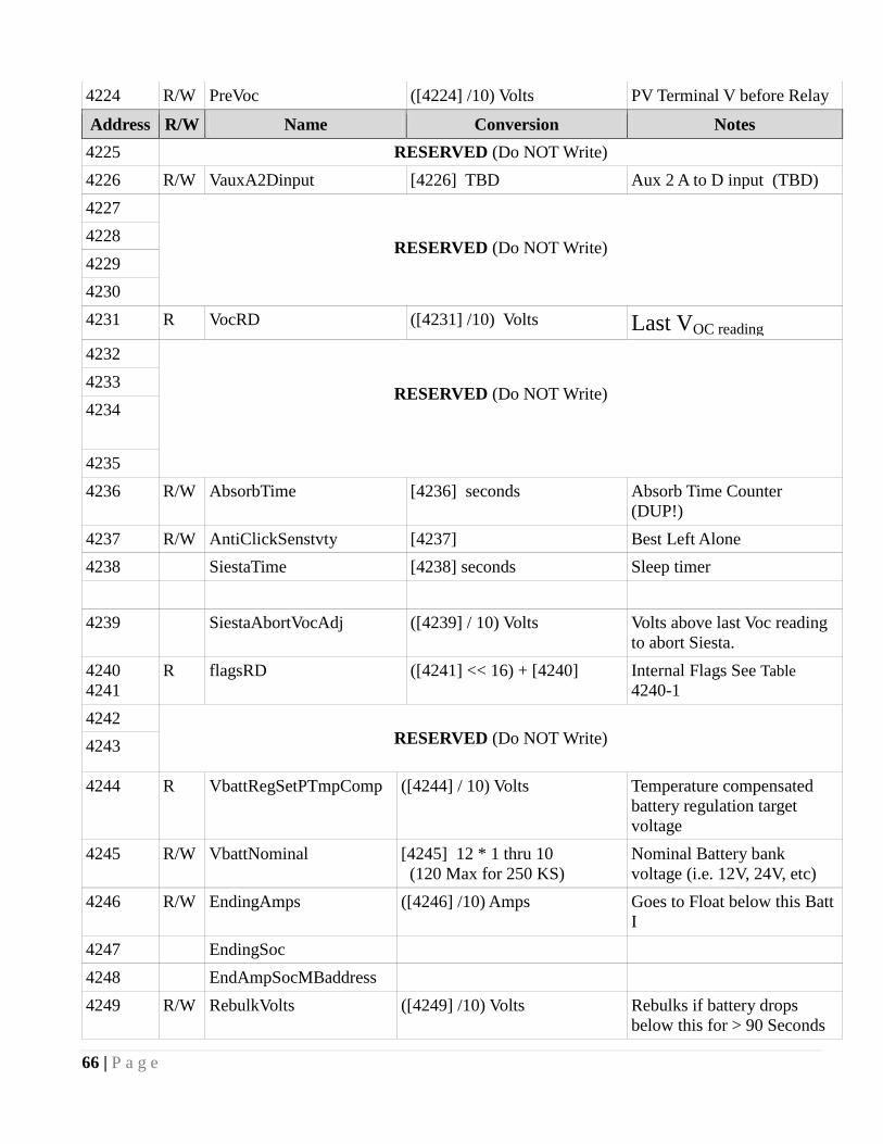
66 | P a g e
4224 R/W PreVoc ([4224] /10) Volts PV Terminal V before Relay
Address R/W Name Conversion Notes
4225 RESERVED (Do NOT Write)
4226 R/W VauxA2Dinput [4226] TBD Aux 2 A to D input (TBD)
4227
RESERVED (Do NOT Write) 4228
4229
4230
4231 R VocRD ([4231] /10) Volts Last VOC reading
4232
RESERVED (Do NOT Write)
4233
4234
4235
4236 R/W AbsorbTime [4236] seconds Absorb Time Counter
(DUP!)
4237 R/W AntiClickSenstvty [4237] Best Left Alone
4238 SiestaTime [4238] seconds Sleep timer
4239 SiestaAbortVocAdj ([4239] / 10) Volts Volts above last Voc reading
to abort Siesta.
4240
4241
R flagsRD ([4241] << 16) + [4240] Internal Flags See Table
4240-1
4242
RESERVED (Do NOT Write)
4243
4244 R VbattRegSetPTmpComp ([4244] / 10) Volts Temperature compensated
battery regulation target
voltage
4245 R/W VbattNominal [4245] 12 * 1 thru 10
(120 Max for 250 KS)
Nominal Battery bank
voltage (i.e. 12V, 24V, etc)
4246 R/W EndingAmps ([4246] /10) Amps Goes to Float below this Batt
I
4247 EndingSoc
4248 EndAmpSocMBaddress
4249 R/W RebulkVolts ([4249] /10) Volts Rebulks if battery drops
below this for > 90 Seconds
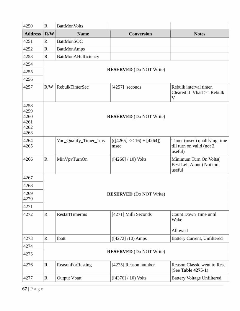
67 | P a g e
4250 R BattMonVolts
Address R/W Name Conversion Notes
4251 R BattMonSOC
4252 R BattMonAmps
4253 R BattMonAHefficiency
4254
RESERVED (Do NOT Write) 4255
4256
4257
R/W RebulkTimerSec [4257] seconds Rebulk interval timer.
Cleared if Vbatt >= Rebulk
V
4258
4259
4260
4261
4262
4263
RESERVED (Do NOT Write)
4264
4265
Voc_Qualify_Timer_1ms (([4265] << 16) + [4264])
msec
Timer (msec) qualifying time
till turn on valid (not 2
useful)
4266 R MinVpvTurnOn ([4266] / 10) Volts Minimum Turn On Volts(
Best Left Alone) Not too
useful
4267
RESERVED (Do NOT Write)
4268
4269
4270
4271
4272 R RestartTimerms [4271] Milli Seconds Count Down Time until
Wake
Allowed
4273 R Ibatt ([4272] /10) Amps Battery Current, Unfiltered
4274
RESERVED (Do NOT Write)
4275
4276 R ReasonForResting [4275] Reason number Reason Classic went to Rest
(See Table 4275-1)
4277 R Output Vbatt ([4376] / 10) Volts Battery Voltage Unfiltered
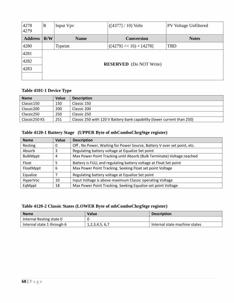
68 | P a g e
4278
4279
R Input Vpv ([4377] / 10) Volts PV Voltage Unfiltered
Address R/W Name Conversion Notes
4280 Typeint ([4279] << 16) + [4278] TBD
4281
RESERVED (Do NOT Write) 4282
4283
Table 4101-1 Device Type
Name Value Description
Classic150 150 Classic 150
Classic200 200 Classic 200
Classic250 250 Classic 250
Classic250 KS 251 Classic 250 with 120 V Battery bank capability (lower current than 250)
Table 4120-1 Battery Stage (UPPER Byte of mbComboChrgStge register)
Name Value Description
Resting 0 Off , No Power, Waiting for Power Source, Battery V over set point, etc.
Absorb 3 Regulating battery voltage at Equalize Set point
BulkMppt 4 Max Power Point Tracking until Absorb (Bulk Terminate) Voltage reached
Float 5 Battery is FULL and regulating battery voltage at Float Set point
FloatMppt 6 Max Power Point Tracking. Seeking Float set point Voltage
Equalize 7 Regulating battery voltage at Equalize Set point
HyperVoc 10 Input Voltage is above maximum Classic operating Voltage
EqMppt 18 Max Power Point Tracking. Seeking Equalize set point Voltage
Table 4120-2 Classic States (LOWER Byte of mbComboChrgStge register)
Name Value Description
Internal Resting state 0 0
Internal state 1 through 6 1,2,3,4,5, 6,7 Internal state machine states

69 | P a g e
Table 4130-1 Info Flag Bits: READ ONLY
Flag Value Description
Classic Over Temperature 0x00000001 Classic Over Temperature if set
EEPROM error 0x00000002 Classic EEprom read/write found an error if set
RESERVED 0x00000004 RESERVED
Equalize In Progress 0x00000008 Equalize Charge stage Active if set
RESERVED 0x00000010 RESERVED
RESERVED 0x00000020 RESERVED
RESERVED 0x00000040 RESERVED
EQ MPPT 0x00000080 Battery V is less than EQ Voltage (EQ MPPT)
In V is Lower Than Out 0x00000100 Input Voltage (PV) is lower than Vbatt if set
Current Limit 0x00000200 User current limit or internal temperature current limt reached
HyperVoc 0x00000400 Hyper Voc PV input is between Vmax and Vmax+Vbatt
RESERVED 0x00000800 RESERVED
RESERVED 0x00001000 RESERVED
Battery Temp Sensor Installed 0x00002000 Battery temperature sensor installed if set
Aux1 State On 0x00004000 Aux 1 ON (aux 1 connector has V or relay closed)
Aux2 State On 0x00008000 Aux 2 ON (aux 2 connector has V present)
GroundFaultF 0x00010000 Ground Fault detected if set
DefCon4ErrF 0x00020000 FET Drive Error if set (lower priority than DefCon3)
ArcFaultF 0x00040000 Arc Fault occurred if set
NegBatCurrentF 0x00080000 Negative battery current if set
DefCon3ErrF 0x00100000 FET error (higher priority and DefCon 4)
XtraInfo2DsplayF 0x00200000 Extra info is available to display (Shading, etc)
PvPartialShadeF 0x00400000 Partial Shade detected during SOLAR sweep
WatchdogResetF 0x00800000 watchdog reset flag indicator (for debugging)
LowBatteryVF 0x01000000 VERY low battery) Vbatt is lower than 8.0 Volts
StackumperF 0x02000000 Stack Jumper is NOT installed if set
EqDoneF 0x04000000 EQ Finished. Resets when mode changed or new day
TempCompShortedF 0x08000000 Indication of shorted Temp Comp if set (all fans should
come on if this is true)
LockJumperF 0x10000000 Lock Jumper is NOT installed if set
XtraJumperF 0x20000000 Extra Jumper is NOT installed if set
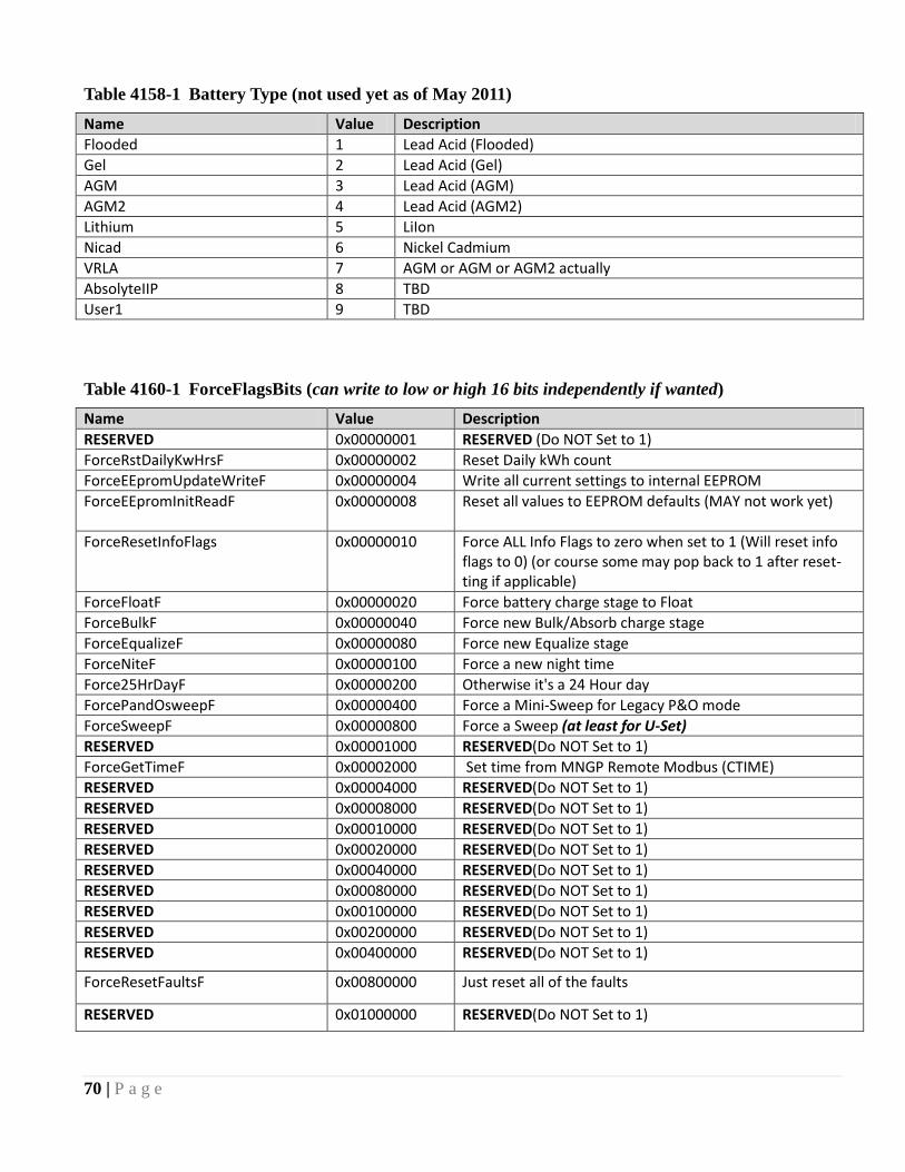
70 | P a g e
Table 4158-1 Battery Type (not used yet as of May 2011)
Name Value Description
Flooded 1 Lead Acid (Flooded)
Gel 2 Lead Acid (Gel)
AGM 3 Lead Acid (AGM)
AGM2 4 Lead Acid (AGM2)
Lithium 5 LiIon
Nicad 6 Nickel Cadmium
VRLA 7 AGM or AGM or AGM2 actually
AbsolyteIIP 8 TBD
User1 9 TBD
Table 4160-1 ForceFlagsBits (can write to low or high 16 bits independently if wanted)
Name Value Description
RESERVED 0x00000001 RESERVED (Do NOT Set to 1)
ForceRstDailyKwHrsF 0x00000002 Reset Daily kWh count
ForceEEpromUpdateWriteF 0x00000004 Write all current settings to internal EEPROM
ForceEEpromInitReadF 0x00000008
Reset all values to EEPROM defaults (MAY not work yet)
ForceResetInfoFlags 0x00000010 Force ALL Info Flags to zero when set to 1 (Will reset info flags to 0) (or course some may pop back to 1 after reset-ting if applicable)
ForceFloatF 0x00000020 Force battery charge stage to Float
ForceBulkF 0x00000040 Force new Bulk/Absorb charge stage
ForceEqualizeF 0x00000080 Force new Equalize stage
ForceNiteF 0x00000100 Force a new night time
Force25HrDayF 0x00000200 Otherwise it's a 24 Hour day
ForcePandOsweepF 0x00000400 Force a Mini-Sweep for Legacy P&O mode
ForceSweepF 0x00000800 Force a Sweep (at least for U-Set)
RESERVED 0x00001000 RESERVED(Do NOT Set to 1)
ForceGetTimeF 0x00002000 Set time from MNGP Remote Modbus (CTIME)
RESERVED 0x00004000 RESERVED(Do NOT Set to 1)
RESERVED 0x00008000 RESERVED(Do NOT Set to 1)
RESERVED 0x00010000 RESERVED(Do NOT Set to 1)
RESERVED 0x00020000 RESERVED(Do NOT Set to 1)
RESERVED 0x00040000 RESERVED(Do NOT Set to 1)
RESERVED 0x00080000 RESERVED(Do NOT Set to 1)
RESERVED 0x00100000 RESERVED(Do NOT Set to 1)
RESERVED 0x00200000 RESERVED(Do NOT Set to 1)
RESERVED 0x00400000 RESERVED(Do NOT Set to 1)
ForceResetFaultsF 0x00800000 Just reset all of the faults
RESERVED 0x01000000 RESERVED(Do NOT Set to 1)

71 | P a g e
Table 4164-1 MPPT MODE†
` Value Description
PV_Uset 0x0001 U-SET MPPT MODE (includes MPPT ENABLED (On) FLAG i.e. if 0x0000 MPPT mode is OFF)
DYNAMIC 0x0003 Slow Dynamic Solar Tracking (old Solar 1 O & P )
Legacy P&O 0x0009 Legacy P & O sweep mode
SOLAR 0x000B Fast SOLAR track (old PV Learn mode)
MICRO HYDRO 0x000D Micro Hydro mode (similar to Legacy P&O)
WIND TRACK 0x0005 Wind Track Mode
WIND LEARN (future mode) 0x0007 Wind Learn Mode (not implemented as of May 2011)
PV COMBO 1 0x000F PV COMBO 1
RESERVED 0x0011 RESERVED
BOOST CHRG 0x0013 Boost Charge Mode (Lower to Higher Voltage, Unimple-mented as of May 2011)
†Bit 0 is the ON/OFF (Enable/Disable) Table shows modes as ON
NOTE: MPPT MODE will automatically revert to OFF during mode change
Table 4207-1 LED Mode
Name Value Description
All Off 0 No LED activity except on startup
Rick Mode 1 Minimal Activity: Remote Yellow LED indicates Current
Limiting or FET Temperature Limit.
Blinky 2 All LEDs Active: Lightshow!
MNGP Red LED : MNGP->Classic MODBUS active
LED 1 3 Status Mode:
MNGP Green LED = Battery Full (Float)
Classic Red LED = Aux 1 Active.
Classic Yellow LED = Aux 2 Active
Classic Blue LED = Unimplemented
LED 2 4 Unimplemented
LED 3 5 Unimplemented

72 | P a g e
Table 4240-1 Internal Flags bits (Read Only) (flagsRD)
Name Value Description
RESERVED 0x00000001 RESERVED
RESERVED 0x00000002 RESERVED
RESERVED 0x00000004 RESERVED
RESERVED 0x00000008 RESERVED
RESERVED 0x00000010 RESERVED
RESERVED 0x00000020 RESERVED
RESERVED 0x00000040 RESERVED
AbsorbTimeRunf 0x00000080 Bulk/Absorb Timer Counting is Enabled
EqTimeRunf 0x00000100 EQualize Timer Run flag
FloatTimeRunf 0x00000200 Float Time accumulate flag
kWhAccumRunf 0x00000400 kiloWatt-hour & Amp-Hour accumulate enabled
RESERVED 0x00000800 RESERVED
AbsorbCountUpf 0x00001000 Absorb Timer is counting UP if set
OK2WriteIVtables 0x00004000 OK to write WindPowerTableV[] & I[]
WindLowflag 0x00008000 Indicates that we turned off because of low power
SweepDwnEnabledf 0x00010000 Slowly Sweeping Down V input
LowLightflag 0x00020000 State 2 detected low light (May not be accurate)
RESERVED 0x00040000 RESERVED
RESERVED 0x00080000 RESERVED
RESERVED 0x00100000 RESERVED
SweepUpEnabledf 0x00200000 Slowly Sweeping UP V input
RESERVED 0x00400000 RESERVED
RESERVED 0x00800000 RESERVED
RESERVED 0x01000000 RESERVED
BattFull 0x02000000 Battery Full, Absorb complete, Float
RESERVED 0x04000000 RESERVED
EqCountUpf 0x08000000 EQ Timer is counting Up
RESERVED 0x10000000 RESERVED
RESERVED 0x20000000 RESERVED
RESERVED 0x40000000 RESERVED
RESERVED 0x80000000 RESERVED
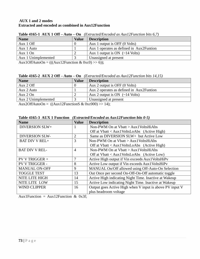
73 | P a g e
AUX 1 and 2 modes
Extracted and encoded as combined in Aux12Function
Table 4165-1 AUX 1 Off – Auto – On (Extracted/Encoded as Aux12Function bits 6,7)
Name Value Description
Aux 1 Off 0 Aux 1 output is OFF (0 Volts)
Aux 1 Auto 1 Aux 1 operates as defined in Aux2Funtion
Aux 1 On 2 Aux 1 output is ON (~14 Volts)
Aux 1 Unimplemented 3 Unassigned at present
Aux1OffAutoOn = (((Aux12Function & 0xc0) >> 6));
Table 4165-2 AUX 2 Off – Auto – On (Extracted/Encoded as Aux12Function bits 14,15)
Name Value Description
Aux 2 Off 0 Aux 2 output is OFF (0 Volts)
Aux 2 Auto 1 Aux 2 operates as defined in Aux2Funtion
Aux 2 On 2 Aux 2 output is ON (~14 Volts)
Aux 2 Unimplemented 3 Unassigned at present
Aux2OffAutoOn = ((Aux12FunctionS & 0xc000) >> 14);
Table 4165-3 AUX 1 Function (Extracted/Encoded as Aux12Function bits 0-5)
Name Value Description
DIVERSION SLW+ 1 Non-PWM On at Vbatt > Aux1VoltsHiAbs
Off at Vbatt < Aux1VoltsLoAbs (Active High)
DIVERSION SLW- 2 Same as DIVERSION SLW+ but Active Low
BAT DIV V REL+ 3 Non-PWM On at Vbatt > Aux1VoltsHiAbs
Off at Vbatt < Aux1VoltsLoAbs (Active High)
BAT DIV V REL- 4 Non-PWM On at Vbatt > Aux1VoltsHiAbs
Off at Vbatt < Aux1VoltsLoAbs (Active Low)
PV V TRIGGER + 7 Active High output if Vin exceeds Aux1VoltsHiPv
PV V TRIGGER - 8 Active Low output if Vin exceeds Aux1VoltsHiPv
MANUAL ON-OFF 9 MANUAL On/Off allowed using Off-Auto-On Selection
TOGGLE TEST 13 Out Once per second On-Off-On-Off automatic toggle
NITE LITE HIGH 14 Active High indicating Night Time. Inactive at Wakeup
NITE LITE LOW 15 Active Low indicating Night Time. Inactive at Wakeup
WIND CLIPPER 16 Output goes Active High when V input is above PV input V
plus headroom voltage
Aux1Function = Aux12Function & 0x3f;

74 | P a g e
Table 4165-4 AUX 2 Function (Extracted/Encoded as Aux12Function bits 8-13)
Name Value Description
DIVERT DGTL F+ 0 Digital Out PWM Battery Diversion (Active High)
DIVERT DGTL F- 1 Digital Out PWM Battery Diversion (Active Low)
BAT DIV V REL+ 2 Digital Out PWM Relative to Charge Stage Voltage
Threshold Diversion (Use It Or Lose It) (Active High)
BAT DIV V REL- 3 Digital Out PWM Relative to Charge Stage Voltage
Threshold Diversion (Use It Or Lose It) (Active Low)
TOGGLE TEST 6 Out Once per second On-Off-On-Off automatic toggle
PV IN TRIG + 7 Active High output if Vin exceeds Aux2VoltsHiPv
PV IN TRIG - 8 Active Low output if Vin exceeds Aux2VoltsHiPv
MANUAL ON-OFF 9 MANUAL On/Off allowed using Off-Auto-On Selection
WIND CLIPPER 10 PWM output Active High when V input is above PV input
V plus headroom voltage
NITE LITE HIGH 11 Active High indicating Night Time. Inactive at Wakeup
NITE LITE LOW 12 Active Low indicating Night Time. Inactive at Wakeup
Aux2Function = (Aux12FunctionS & 0x3f00) >> 8; (Digital/Analog Input/Output)
Table 4187-1 EnableFlags bits [4187]
Name Value Description
GroundFaultEn 0x0001 Ground Fault Protection Enabled when Set to 1
ArcFaultEn 0x0002 Arc Fault Protection Enabled when Set to 1
RESERVED 0x0004 RESERVED (Do NOT set this bit)
PvPartialShadeEn 0x0008 Partial Shade reporting Enabled when Set to 1
RESERVED 0x0010 RESERVED (Do NOT set this bit)
DefCon3ErrEn 0x0020 DefCon3 Error reporting enabled if set to 1
DefCon4ErrEn 0x0040 DefCon3 Error reporting enabled if set to 1
PwmLowMaxFlag 0x0080 Low Max Enabled if Set to 1 (Low Vin - Vout)
RESERVED 0x0100 RESERVED (Do NOT Set to 1)
RESERVED 0x0200 RESERVED (Do NOT Set to 1)
BumpWindI 0x0400 When adjusting wind curve, automatically ―bumps‖
adjacent current set points out of the way if set to 1
DivrsnAbsEqTmrEn 0x0800 Enables Absorb & EQ timer counting when Aux
functions are diverting if set to 1.
RESERVED 0x1000 RESERVED (Do NOT Set to 1)
RESERVED 0x4000 RESERVED (Do NOT Set to 1)
RESERVED 0x8000 RESERVED (Do NOT Set to 1)
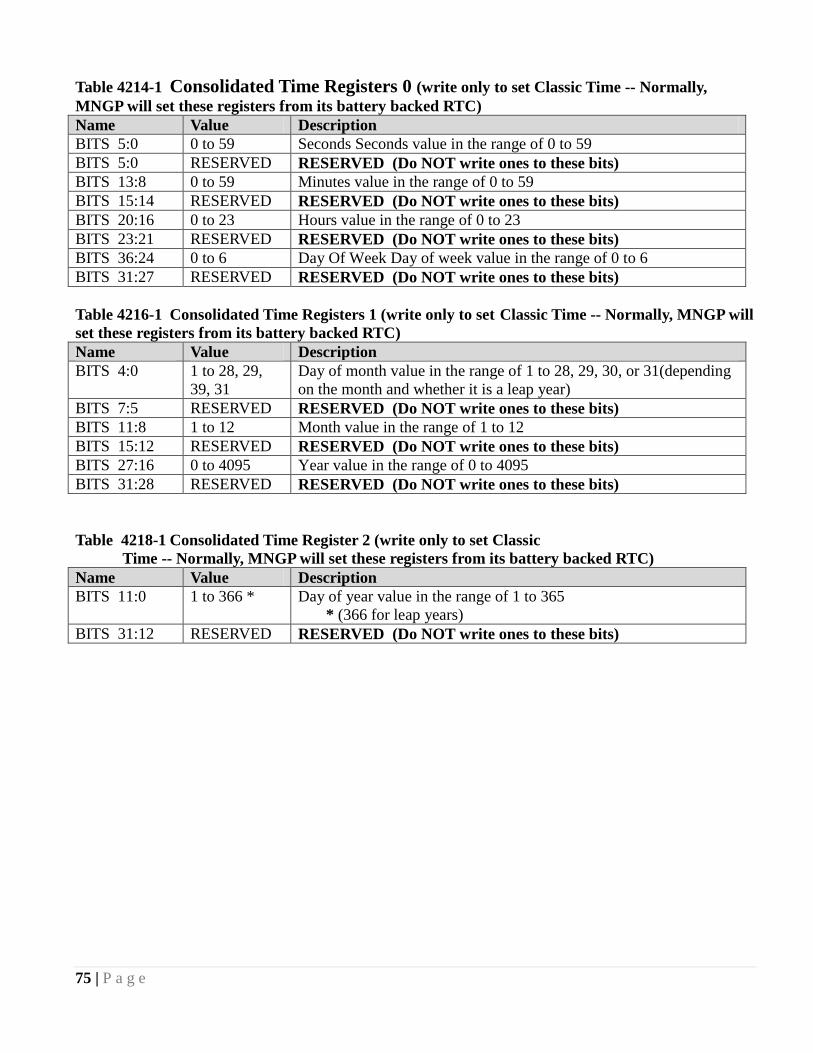
75 | P a g e
Table 4214-1 Consolidated Time Registers 0 (write only to set Classic Time -- Normally,
MNGP will set these registers from its battery backed RTC)
Name Value Description
BITS 5:0 0 to 59 Seconds Seconds value in the range of 0 to 59
BITS 5:0 RESERVED RESERVED (Do NOT write ones to these bits)
BITS 13:8 0 to 59 Minutes value in the range of 0 to 59
BITS 15:14 RESERVED RESERVED (Do NOT write ones to these bits)
BITS 20:16 0 to 23 Hours value in the range of 0 to 23
BITS 23:21 RESERVED RESERVED (Do NOT write ones to these bits)
BITS 36:24 0 to 6 Day Of Week Day of week value in the range of 0 to 6
BITS 31:27 RESERVED RESERVED (Do NOT write ones to these bits)
Table 4216-1 Consolidated Time Registers 1 (write only to set Classic Time -- Normally, MNGP will
set these registers from its battery backed RTC)
Name Value Description
BITS 4:0 1 to 28, 29,
39, 31
Day of month value in the range of 1 to 28, 29, 30, or 31(depending
on the month and whether it is a leap year)
BITS 7:5 RESERVED RESERVED (Do NOT write ones to these bits)
BITS 11:8 1 to 12 Month value in the range of 1 to 12
BITS 15:12 RESERVED RESERVED (Do NOT write ones to these bits)
BITS 27:16 0 to 4095 Year value in the range of 0 to 4095
BITS 31:28 RESERVED RESERVED (Do NOT write ones to these bits)
Table 4218-1 Consolidated Time Register 2 (write only to set Classic
Time -- Normally, MNGP will set these registers from its battery backed RTC)
Name Value Description
BITS 11:0 1 to 366 * Day of year value in the range of 1 to 365
* (366 for leap years)
BITS 31:12 RESERVED RESERVED (Do NOT write ones to these bits)
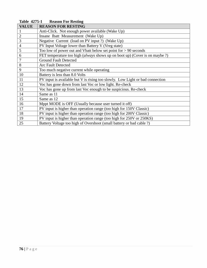
76 | P a g e
Table 4275-1 Reason For Resting
VALUE REASON FOR RESTING
1 Anti-Click. Not enough power available (Wake Up)
2 Insane Ibatt Measurement (Wake Up)
3 Negative Current (load on PV input ?) (Wake Up)
4 PV Input Voltage lower than Battery V (Vreg state)
5 Too low of power out and Vbatt below set point for > 90 seconds
6 FET temperature too high (always shows up on boot up) (Cover is on maybe ?)
7 Ground Fault Detected
8 Arc Fault Detected
9 Too much negative current while operating
10 Battery is less than 8.0 Volts
11 PV input is available but V is rising too slowly. Low Light or bad connection
12 Voc has gone down from last Voc or low light. Re-check
13 Voc has gone up from last Voc enough to be suspicious. Re-check
14 Same as 11
15 Same as 12
16 Mppt MODE is OFF (Usually because user turned it off)
17 PV input is higher than operation range (too high for 150V Classic)
18 PV input is higher than operation range (too high for 200V Classic)
19 PV input is higher than operation range (too high for 250V or 250KS)
25 Battery Voltage too high of Overshoot (small battery or bad cable ?)

77 | P a g e
The network registers are all Read/Write. You may write any values to these registers, however this may
result in erratic operation in some instances.
To set A static IP address, be sure to clear the DHCP bit in register 20481 before writing the static values
to the
Network
Address Name Units Description
20481 IP Settings [20481] Network Settings Flags. See
Table 20481-1
20482
20483
IP Address [20483]MSB . [20483]LSB .
[20482]MSB . [20482]LSB
The IP address of the
Classic†
20484
20485
Gateway Address [20485]MSB . [20485]LSB .
[20484]MSB . [20484]LSB
Network Gateway Address. †
20486
20487
Subnet [20487]MSB . [20487]LSB .
[20486]MSB . [20486]LSB
Network Subnet Mask†
20488
20489
DNS_1 [20489]MSB . [20489]LSB .
[20488]MSB . [20488]LSB
Primary DNS Address†
20490
20491
DNS_2 [20491]MSB . [20491]LSB .
[20490]MSB . [20490]LSB
Secondary/Alternate DNS
Address†
† Read Only if the DHCP flag is set. To assign a static IP to the Classic, first clear the DHCP flag in the IP
Settings Register (20481).
Table 20481-1
Name Value Description
DHCP 0x0001 Set this bit to enable DHCP.
Web Access 0x0002 Set this bit to enable online access to your Classic
through http://www.mymidnite.com
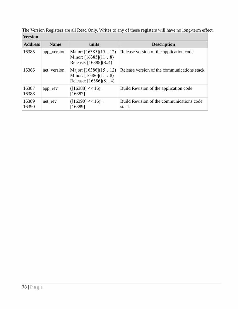
78 | P a g e
The Version Registers are all Read Only. Writes to any of these registers will have no long-term effect.
Version
Address Name units Description
16385 app_version Major: [16385](15…12)
Minor: [16385](11…8)
Release: [16385](8..4)
Release version of the application code
16386 net_version, Major: [16386](15…12)
Minor: [16386](11…8)
Release: [16386](8…4)
Release version of the communications stack
16387
16388
app_rev ([16388] << 16) +
[16387]
Build Revision of the application code
16389
16390
net_rev ([16390] << 16) +
[16389]
Build Revision of the communications code
stack

79 | P a g e
Communication Statistics are all Read/Write registers. You may write any value to these registers which
will be incremented should the trigger for that counter occur. The most useful type of write may be to
periodically reset the counters to zero. These are all lifetime counters and due to the number of MODBUS
transactions may overflow to 0.
Communication Statistics
Address Name units Description
Master / In Bus Interface
10001
10002
rx_ok
([10002] << 16) +
[10001]
Number of correctly received packets
10003
10004
rx_crc_err ([10004] << 16) +
[10003]
Number of packets received with crc errors
10005
10006
requested_ok ([10006] << 16) +
[10005]
Number of transactions originating from
this unit that completed successfully
10007
10008
requested_err ([10008] << 16) +
[10007]
Number of transactions originating from
this unit that failed
10009
10010
forwarded ([10010] << 16) +
[10009]
Number of packets forwarded through this
interface
10011
10012
broadcast ([10012] << 16) +
[10011]
Number of broadcast packets received
10013
10014
dropped_busy ([10014] << 16) +
(10013)
Number of packets dropped due to the
interface being busy.
10015
10016 RESERVED
Slave / Out bus interface
10017
10018
rx_ok
([10018] << 16) +
[10007]
Number of correctly received packets
10019
10020
rx_crc_err ([10020] << 16) +
[10020]
Number of packets received with crc errors
10021
10022
requested_ok ([10022] << 16) +
[10021]
Number of transactions originating from
this unit that completed successfully
10023
10024
requested_err ([10024] << 16) +
[10023]
Number of transactions originating from
this unit that failed
10025
10026
forwarded ([10026] << 16) +
[10025]
Number of packets forwarded through this
interface
10027
10028
broadcast ([10028] << 16) +
[10027]
Number of broadcast packets received
10029
10030
dropped_busy ([10030] << 16) +
[10029]
Number of packets dropped due to the
interface being busy.
10031
10032 RESERVED
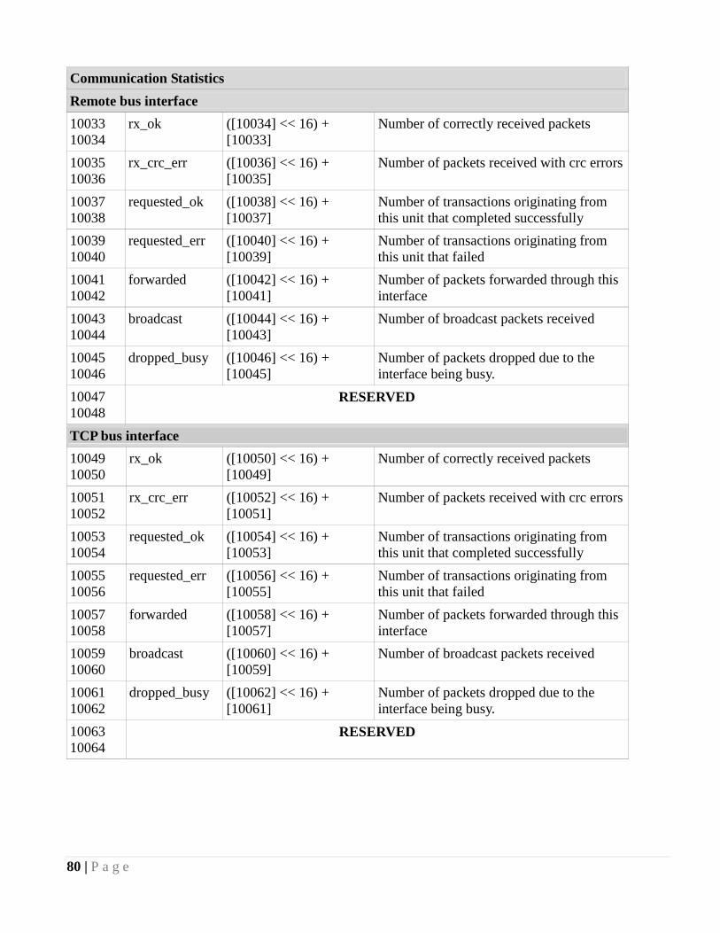
80 | P a g e
Communication Statistics
Remote bus interface
10033
10034
rx_ok
([10034] << 16) +
[10033]
Number of correctly received packets
10035
10036
rx_crc_err ([10036] << 16) +
[10035]
Number of packets received with crc errors
10037
10038
requested_ok ([10038] << 16) +
[10037]
Number of transactions originating from
this unit that completed successfully
10039
10040
requested_err ([10040] << 16) +
[10039]
Number of transactions originating from
this unit that failed
10041
10042
forwarded ([10042] << 16) +
[10041]
Number of packets forwarded through this
interface
10043
10044
broadcast ([10044] << 16) +
[10043]
Number of broadcast packets received
10045
10046
dropped_busy ([10046] << 16) +
[10045]
Number of packets dropped due to the
interface being busy.
10047
10048 RESERVED
TCP bus interface
10049
10050
rx_ok
([10050] << 16) +
[10049]
Number of correctly received packets
10051
10052
rx_crc_err ([10052] << 16) +
[10051]
Number of packets received with crc errors
10053
10054
requested_ok ([10054] << 16) +
[10053]
Number of transactions originating from
this unit that completed successfully
10055
10056
requested_err ([10056] << 16) +
[10055]
Number of transactions originating from
this unit that failed
10057
10058
forwarded ([10058] << 16) +
[10057]
Number of packets forwarded through this
interface
10059
10060
broadcast ([10060] << 16) +
[10059]
Number of broadcast packets received
10061
10062
dropped_busy ([10062] << 16) +
[10061]
Number of packets dropped due to the
interface being busy.
10063
10064 RESERVED
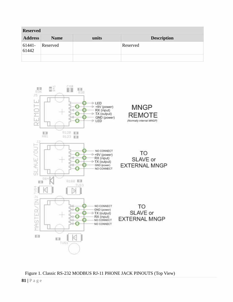
81 | P a g e
Reserved
Address Name units Description
61441-
61442
Reserved Reserved
Figure 1. Classic RS-232 MODBUS RJ-11 PHONE JACK PINOUTS (Top View)
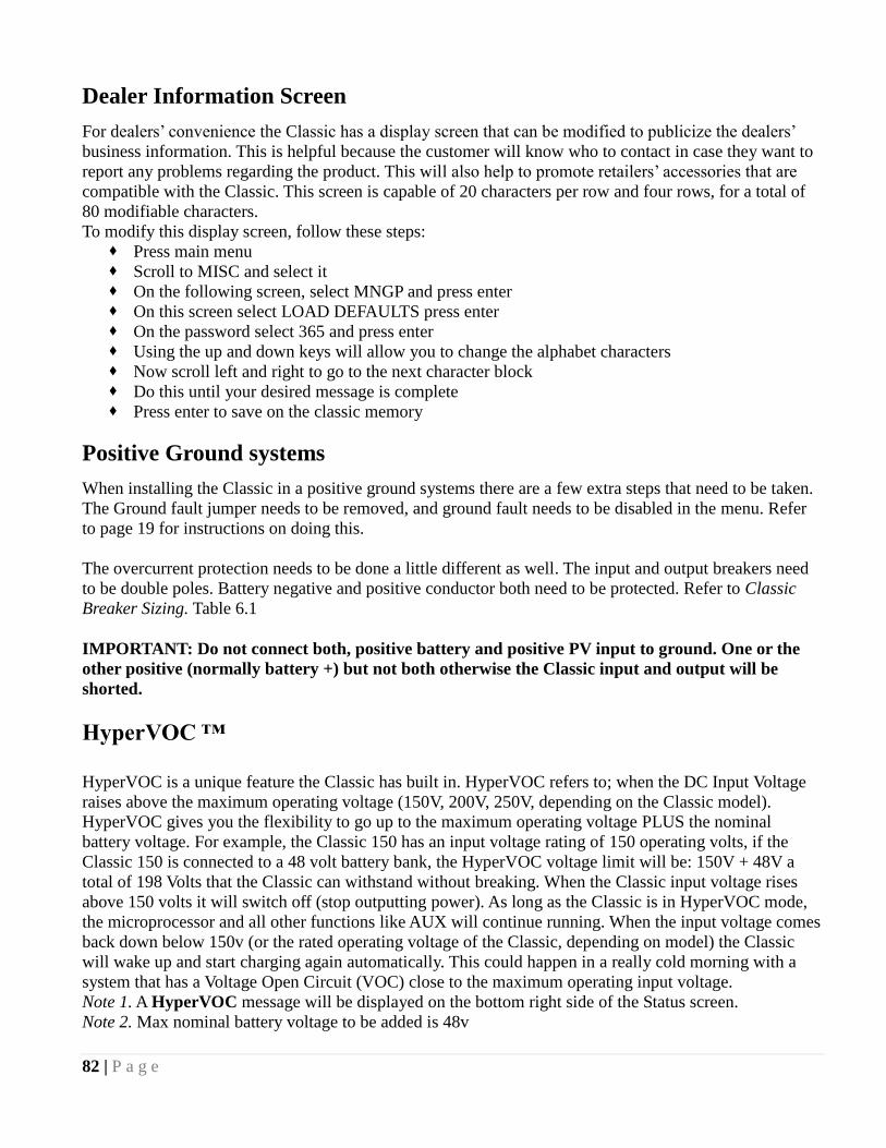
82 | P a g e
Dealer Information Screen
For dealers‘ convenience the Classic has a display screen that can be modified to publicize the dealers‘
business information. This is helpful because the customer will know who to contact in case they want to
report any problems regarding the product. This will also help to promote retailers‘ accessories that are
compatible with the Classic. This screen is capable of 20 characters per row and four rows, for a total of
80 modifiable characters.
To modify this display screen, follow these steps:
Press main menu
Scroll to MISC and select it
On the following screen, select MNGP and press enter
On this screen select LOAD DEFAULTS press enter
On the password select 365 and press enter
Using the up and down keys will allow you to change the alphabet characters
Now scroll left and right to go to the next character block
Do this until your desired message is complete
Press enter to save on the classic memory
Positive Ground systems
When installing the Classic in a positive ground systems there are a few extra steps that need to be taken.
The Ground fault jumper needs to be removed, and ground fault needs to be disabled in the menu. Refer
to page 19 for instructions on doing this.
The overcurrent protection needs to be done a little different as well. The input and output breakers need
to be double poles. Battery negative and positive conductor both need to be protected. Refer to Classic
Breaker Sizing. Table 6.1
IMPORTANT: Do not connect both, positive battery and positive PV input to ground. One or the
other positive (normally battery +) but not both otherwise the Classic input and output will be
shorted.
HyperVOC ™
HyperVOC is a unique feature the Classic has built in. HyperVOC refers to; when the DC Input Voltage
raises above the maximum operating voltage (150V, 200V, 250V, depending on the Classic model).
HyperVOC gives you the flexibility to go up to the maximum operating voltage PLUS the nominal
battery voltage. For example, the Classic 150 has an input voltage rating of 150 operating volts, if the
Classic 150 is connected to a 48 volt battery bank, the HyperVOC voltage limit will be: 150V + 48V a
total of 198 Volts that the Classic can withstand without breaking. When the Classic input voltage rises
above 150 volts it will switch off (stop outputting power). As long as the Classic is in HyperVOC mode,
the microprocessor and all other functions like AUX will continue running. When the input voltage comes
back down below 150v (or the rated operating voltage of the Classic, depending on model) the Classic
will wake up and start charging again automatically. This could happen in a really cold morning with a
system that has a Voltage Open Circuit (VOC) close to the maximum operating input voltage.
Note 1. A HyperVOC message will be displayed on the bottom right side of the Status screen.
Note 2. Max nominal battery voltage to be added is 48v

83 | P a g e
HyperVOC ™ Origins
HyperVOC can be useful in overcoming an industry shortcoming in charging 48 volt battery‘s with
standard panels. For example let‘s take a sample system with Solar World 165‘s that have a VOC of
44.1vdc. The industry has limited us to 2 of these panels in series making it hard to charge a 48vdc battery
on hot summer days. With the Classic we designed in Hyper VOC to allow you to run 3 of these in series.
3 panels at 44.1vdc will give you a total VOC of 132.3vdc. When temperature compensated for cold
climates to 125% gives you 165vdc. This is above the maximum safe limits for most controllers but falls
well into the Hyper VOC range of the Classic. We do have to use Hyper VOC wisely though if we abuse
it the Controller will never wake up in colder weather.
Troubleshooting

84 | P a g e
Technical information
Specifications Electrical
Model Classic150 Classic200 Classic250 Classic250KS
Operating Volts in 150VDC 200VDC 250VDC 250VDC
Max Hyper VOC 150+battery 200+battery 250+battery 250+battery
*Battery Charge Volts 12-93 volts 12-93 volts 12-93 volts 12-150 volts
**Absolute Current
Output at 25°C
96a at 12v battery
94a at 24v battery
83a at 48v battery
74a at 12v battery
70a at 24v battery
65a at 48v battery
60a at 12v battery
62a at 24v battery
55a at 48v battery
40a at 120v battery
De-rate current
at 40°C+ 80 amperes 66 amperes 52 amperes 33 amperes
Environment -40c to 40c
Dimensions of Classic 14.87‖X 5.95‖X 4.00‖ 378mm X 151mm X 102mm
Dimensions of Box 19.00‖X 8.50‖X 5.70‖ 483mm X 216mm xX145mm
Shipping Weight 11.5 lb 4.9 kg
NOTE: Current output ratings were measured with 75% of the PV array‘s VOC (Open Circuit Voltage)
*NOTE: Calculated by adding battery voltage to the maximum input operating voltage (48V battery max)
* **NOTE: Measurement Accuracies: +- 0.12v, offset calibration adjustment maybe necessary
Table 6.1

85 | P a g e
Specifications Mechanical
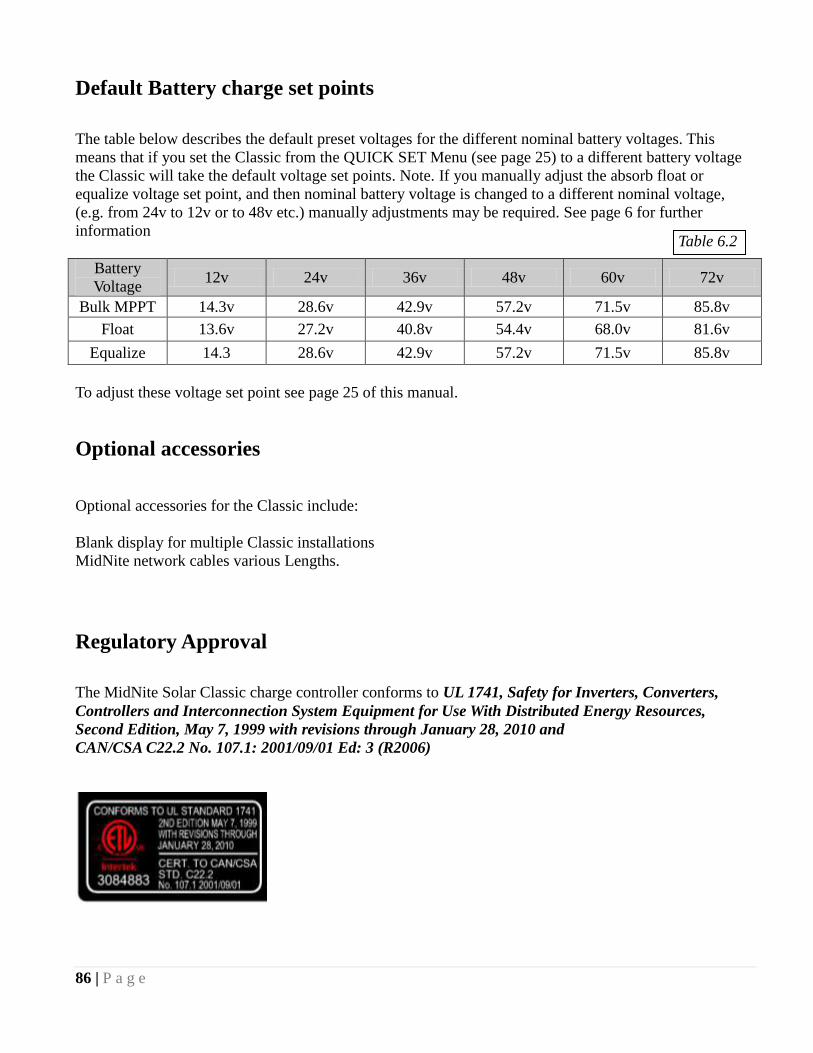
86 | P a g e
Default Battery charge set points
The table below describes the default preset voltages for the different nominal battery voltages. This
means that if you set the Classic from the QUICK SET Menu (see page 25) to a different battery voltage
the Classic will take the default voltage set points. Note. If you manually adjust the absorb float or
equalize voltage set point, and then nominal battery voltage is changed to a different nominal voltage,
(e.g. from 24v to 12v or to 48v etc.) manually adjustments may be required. See page 6 for further
information
Battery
Voltage 12v 24v 36v 48v 60v 72v
Bulk MPPT 14.3v 28.6v 42.9v 57.2v 71.5v 85.8v
Float 13.6v 27.2v 40.8v 54.4v 68.0v 81.6v
Equalize 14.3 28.6v 42.9v 57.2v 71.5v 85.8v
To adjust these voltage set point see page 25 of this manual.
Optional accessories
Optional accessories for the Classic include:
Blank display for multiple Classic installations
MidNite network cables various Lengths.
Regulatory Approval
The MidNite Solar Classic charge controller conforms to UL 1741, Safety for Inverters, Converters,
Controllers and Interconnection System Equipment for Use With Distributed Energy Resources,
Second Edition, May 7, 1999 with revisions through January 28, 2010 and
CAN/CSA C22.2 No. 107.1: 2001/09/01 Ed: 3 (R2006)
Table 6.2
87 | P a g e
Warranty
MidNite Solar's Classic comes with a standard 5 year warranty we will repair or replace the Classic at no
charge to the consumer during this 5 year period
End of Warranty tune up
MidNite Solar offers a industry first Tune up / Extended Warranty. 6 months prior to the end of the
warranty period Customers can ship their Classic back to MidNite Solar with a check for $125 dollars and
we will replace any wearable items like the fans and the capacitors and in general tune the Classic up.
This will also extend the warranty by 2 additional years as well.

88 | P a g e
Aux 2
IN/OUT
+
+ - -
Aux 1 RELAY/OUT
Aux 1 and Aux 2 Graphs/Jumpers
Figure 3.0 shows the two Aux port terminals, with their respective
polarities. These terminals are located at the bottom of the
power board below the battery temperature jack. Use a mini
flat head screw driver to tighten the screws. The jumpers are
described in the section below.
In order to select operation of Aux 1 between relay contact or 12v output JP6 and JP8 need to be
configured accordingly following the instructions provided in this section.
When Aux 1 is used to supply 12v out, JP6 and JP8 have to be in the position shown in Figure 3.1. The
basic schematic of how this works is shown in Figure 3.2. The 12v out is more like 14.5v. The maximum
current from Aux 1 should not exceed 200mA. The Aux 1 output can be set to operate at either Active
High (12V) or Active Low (0V) when the Aux 1 function condition is true. For more information see
Table 2.1, page 31.
To configure Aux 1 to use the internal relay, JP6 and JP8 have to be in the position shown in Figure 3.4.
This configuration is commonly known as ―dry contact‖ because it does not provide 12v at the Aux1
terminals; it acts more like an isolated switch (to the ratings of the relay). The Aux 1 output can be set to
operate at either normally open, (Active High) or normally closed (Active Low) when the Aux 1 function
condition is true. For more information see Table 2.1, page 31. This is ideal for an Auto Gen Start.
Figure 3.1 JP6 and JP8 positioned to supply 12v out of the Aux 1 terminals
Figure 3.2
Figure 3.3
Figure 3.4
Figure 3.0

89 | P a g e
Aux 1 Voltage-Time Relation (Relay/12v)
Aux 1 Function Graph shows the relationship between voltage and time of AUX 1. (The axis labeled
VOLTAGE could be battery, PV, wind input voltage, etc. depending on the function selected by the user)
VHIGH is the upper voltage limit, as soon as the voltage reaches this limit the Delay time will then start,
as soon as the Delay time expires AUX1 will change state and stay there until the voltage drops below
VLOW set point, then another timer called Hold Time will start and when this expires the out put will go
back to the original state.
Aux 2 Voltage-Time Relation (PWM)
The graph below describes the relation in Aux 2, between voltage and time. The difference in Aux 2 is the
use of PWM running at a hundreds of Hz rate and is suitable for use with Solid State Relays (SSRs). The
way this works is: user sets a desired threshold and a width voltage, this means that at the desired voltage
(VOLTS), the aux will start to PWM and it has to go above or below the width to completely change
states (from 0v to 12v, or from 12v to 0v depending on the user selection, active high or active low). This
gives a much smoother transition. For more information see; Configuring Auxiliary Input/Output. Page 29
PWM PWM
Figure 3.5
Figure 3.6

90 | P a g e
Classic Breaker sizing
Table 6.1
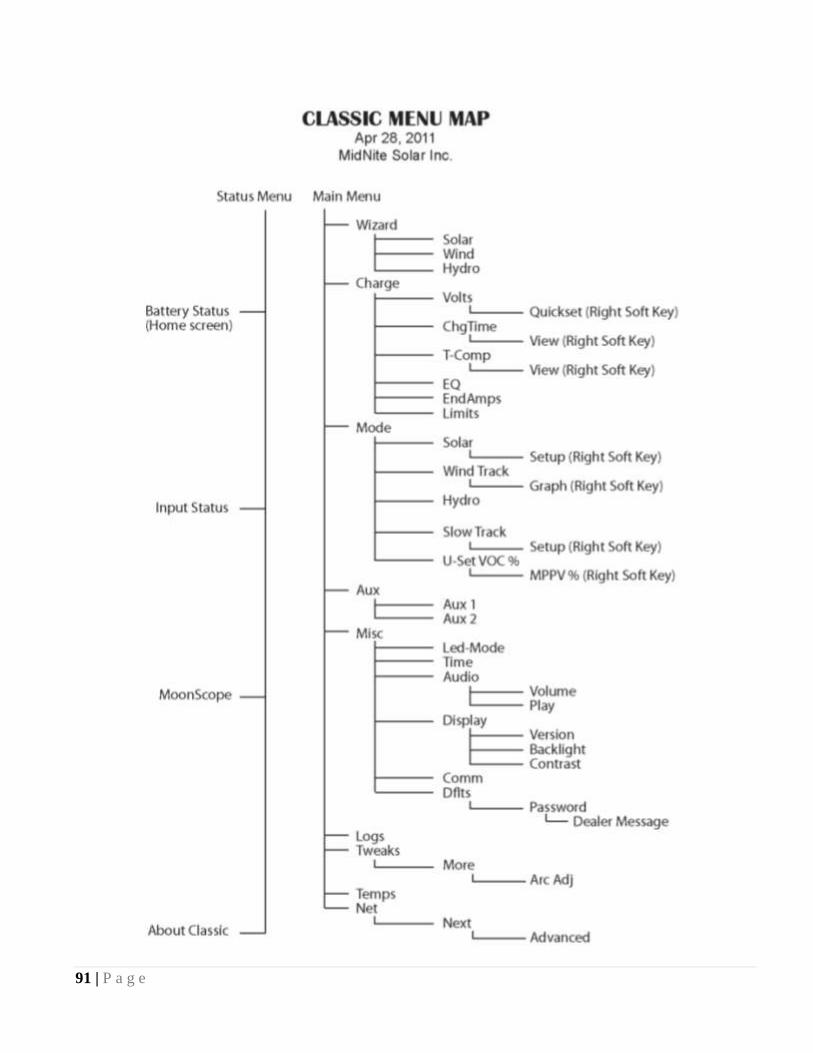
91 | P a g e
Classic Menu Map