Embed Size (px)
Citation preview

MIKE 21 Maritime
Frequency Response Calculator
User Guide
MIKE 2017

2

PLEASE NOTE
COPYRIGHT This document refers to proprietary computer software which is pro-tected by copyright. All rights are reserved. Copying or other repro-duction of this manual or the related programs is prohibited without prior written consent of DHI. For details please refer to your 'DHI Software Licence Agreement'.
LIMITED LIABILITY The liability of DHI is limited as specified in Section III of your 'DHI Software Licence Agreement':
'IN NO EVENT SHALL DHI OR ITS REPRESENTATIVES (AGENTS AND SUPPLIERS) BE LIABLE FOR ANY DAMAGES WHATSOEVER INCLUDING, WITHOUT LIMITATION, SPECIAL, INDIRECT, INCIDENTAL OR CONSEQUENTIAL DAMAGES OR DAMAGES FOR LOSS OF BUSINESS PROFITS OR SAVINGS, BUSINESS INTERRUPTION, LOSS OF BUSINESS INFORMA-TION OR OTHER PECUNIARY LOSS ARISING OUT OF THE USE OF OR THE INABILITY TO USE THIS DHI SOFTWARE PRODUCT, EVEN IF DHI HAS BEEN ADVISED OF THE POSSI-BILITY OF SUCH DAMAGES. THIS LIMITATION SHALL APPLY TO CLAIMS OF PERSONAL INJURY TO THE EXTENT PERMIT-TED BY LAW. SOME COUNTRIES OR STATES DO NOT ALLOW THE EXCLUSION OR LIMITATION OF LIABILITY FOR CONSE-QUENTIAL, SPECIAL, INDIRECT, INCIDENTAL DAMAGES AND, ACCORDINGLY, SOME PORTIONS OF THESE LIMITATIONS MAY NOT APPLY TO YOU. BY YOUR OPENING OF THIS SEALED PACKAGE OR INSTALLING OR USING THE SOFT-WARE, YOU HAVE ACCEPTED THAT THE ABOVE LIMITATIONS OR THE MAXIMUM LEGALLY APPLICABLE SUBSET OF THESE LIMITATIONS APPLY TO YOUR PURCHASE OF THIS SOFT-WARE.'
3

4 Frequency Response Calculator - © DHI

CONTENTS
1 About this User Guide . . . . . . . . . . . . . . . . . . . . . . . . . . . . . . . . 71.1 Purpose . . . . . . . . . . . . . . . . . . . . . . . . . . . . . . . . . . . . . 71.2 Assumed User Background . . . . . . . . . . . . . . . . . . . . . . . . . . . 71.3 General Editor Layout . . . . . . . . . . . . . . . . . . . . . . . . . . . . . . 8
1.3.1 Navigation tree . . . . . . . . . . . . . . . . . . . . . . . . . . . . . 81.3.2 Editor window . . . . . . . . . . . . . . . . . . . . . . . . . . . . . . 81.3.3 Validation window . . . . . . . . . . . . . . . . . . . . . . . . . . . . 8
1.4 Online Help . . . . . . . . . . . . . . . . . . . . . . . . . . . . . . . . . . . . 8
2 Introduction . . . . . . . . . . . . . . . . . . . . . . . . . . . . . . . . . . . . . . 92.1 Short Description . . . . . . . . . . . . . . . . . . . . . . . . . . . . . . . . . 9
3 Reference Manual . . . . . . . . . . . . . . . . . . . . . . . . . . . . . . . . . . 113.1 Vessel Configuration . . . . . . . . . . . . . . . . . . . . . . . . . . . . . . . 113.2 Vessel Instance . . . . . . . . . . . . . . . . . . . . . . . . . . . . . . . . . 11
3.2.1 Vessel characteristics . . . . . . . . . . . . . . . . . . . . . . . . . . 113.2.2 Vessel view . . . . . . . . . . . . . . . . . . . . . . . . . . . . . . . 14
3.3 Computational Settings . . . . . . . . . . . . . . . . . . . . . . . . . . . . . . 163.4 Wave Drift Forces . . . . . . . . . . . . . . . . . . . . . . . . . . . . . . . . 173.5 Outputs . . . . . . . . . . . . . . . . . . . . . . . . . . . . . . . . . . . . . . 17
3.5.1 Vessel response . . . . . . . . . . . . . . . . . . . . . . . . . . . . 183.5.2 Added mass . . . . . . . . . . . . . . . . . . . . . . . . . . . . . . 183.5.3 Damping . . . . . . . . . . . . . . . . . . . . . . . . . . . . . . . . 183.5.4 Drift forces . . . . . . . . . . . . . . . . . . . . . . . . . . . . . . . 183.5.5 Response amplitude operator . . . . . . . . . . . . . . . . . . . . . 193.5.6 Exciting forces . . . . . . . . . . . . . . . . . . . . . . . . . . . . . 19
4 References . . . . . . . . . . . . . . . . . . . . . . . . . . . . . . . . . . . . . . . 21
Index . . . . . . . . . . . . . . . . . . . . . . . . . . . . . . . . . . . . . . . . . . . . . 23
5

6 Frequency Response Calculator - © DHI

Purpose
1 About this User Guide
1.1 Purpose
The main purpose of this User Guide is to get you started in the use of the new MIKE 21 Mooring Analysis (MA) modelling system, for analysis of moored vessels (or a floating body in general) subject to wave, current and wind forcing, whether located in ports, coastal or offshore areas. The effect of breakwaters and other port structures on the wave field is included in the model.
The MIKE 21 MA modelling system consists of two applications in the MIKE 21 product group Maritime, which works together in a full workflow:
1. Frequency Response Calculator
2. MIKE 21 MA
This guide will explain how to operate the Frequency Response Calculator (FRC), which is the first application to consider in a mooring analysis work-flow.
This User Guide is complemented by the Online Help.
The MIKE 21 MA modelling system, is a further commercialisation and devel-opment of the previously released DHI model called DVRS (Dynamic Vessel Response Simulator) as well as the DHI internal tool known as WAMSIM /1/. Therefore reference papers and past studies refer as well to the MIKE 21 MA modelling system as such.
1.2 Assumed User Background
Although the MIKE 21 MA suite of applications have been designed carefully with emphasis on a logical and user-friendly interface, and although the User Guide and Online Help contain modelling procedures and a large amount of reference material, common sense is always needed in any practical applica-tion.
In this case, "common sense" means a background in hydrodynamics and flow-structure interaction, which is sufficient for you to be able to check whether the results are reasonable or not. This User Guide is not intended as a substitute for a basic knowledge of the area in which you are working: Mathematical modelling of flow-structure interaction.
It is assumed that you are familiar with the basic elements of MIKE Zero: File types and file editors, the Plot Composer, the MIKE Zero Toolbox, the Data Viewer and the Mesh Generator. An introduction to these can be found in the documentation.
7

About this User Guide
1.3 General Editor Layout
The Frequency Response Calculator (FRC) setup editor consists of three separate panes.
1.3.1 Navigation tree
To the left is a navigation tree, that shows the structure of the model setup file, and is used to navigate through the separate sections of the file. By selecting an item in this tree, the corresponding editor is shown in the central pane of the setup editor.
1.3.2 Editor window
The editor for the selected section is shown in the central pane. The content of this editor is specific for the selected section, and might contain several property pages.
The FRC editor windows offer the user a vessel hull rendering tool, where characteristics like:
Spatial vessel extent (Length Over All (LOA), beam (B) and height)
Volume displacement of the vessel/floating body, at a particular draft
Waterline and deck plane contours in the XY plane
are instantly computed and visualized, in order to grant the user quantitative and visual information of the conditions for the vessel/floating body.
Further options may be available in the context menu depending on the sec-tion being edited.
1.3.3 Validation window
The bottom pane of the editor shows possible validation errors, and is dynamically updated to reflect the current status of the setup specifications. By double-clicking on an error in this window, the editor in which this error occurs will be selected.
1.4 Online Help
To access the help associated with a specific dialog page, press the F1-key on the keyboard after opening the editor and activating the specific property page.
8 Frequency Response Calculator - © DHI

Short Description
2 Introduction
Frequency Response Calculator (FRC) is an independent software applica-tion to generate geometric, hydrostatic and computational response data. It can be applied in two ways:
As the basis for a further time-domain computation of the temporal dynamics of a vessel/floating body exposed to incident environmental forcings (wave, wind, current).
As an independent stand-alone tool for a specific analysis of for example Response Amplitude Operators (RAO) and added mass for a ves-sel/floating body of any geometry and loading conditions.
It is the first of these applications, which is the primary intended purpose of the FRC. In such a workflow the user will:
1. Generate the fundamental necessary vessel/floating body data (geomet-ric and frequency response data) with FRC (step 1)
2. Load the generated data into the MIKE 21 Mooring Analysis (MA) editor, which subsequently can compute time-domain results for the ves-sel/floating body (step 2).
FRC will thus typically be part of a "double team" together with the MIKE 21 MA application.
A further description of how the two applications depend on each other is found in the User Guide for MIKE 21 MA.
2.1 Short Description
FRC offers a graphical environment, where the user on basis of:
A supplied 3D panelized grid representing the vessel/floating body
Relevant hydrodynamic characteristics
can set up a model of a static vessel/floating body, with local static conditions.
When a full setup has been created, a simulation with the associated engine can be launched, leading to a series of generated results, storing a series of relevant data.
Static spatial data representing the physical system:
The geometric XYZ data of the full vessel hull
Vessel statistics of dimensions + volume displacement
Depth and draft, deck plane values
9

Introduction
Computational response data for the vessel/floating body, which is also rele-vant as input data in a subsequent time-domain computation in MIKE 21 MA:
Hydrostatic and gravitational restoring matrix (geometrically dependent)
Radiation potentials (frequency dependent).
Added mass (frequency dependent)
Radiation damping (frequency dependent)
Wave drift forces (frequency dependent)
Generation of RAOs for the vessel/floating body
Generation of exciting forces for the vessel/floating body
Some of this data can be of isolated interest to inspect, but the main perspec-tive is that this data is stored into a single binary file (.vre), which is subse-quently loaded into the MIKE 21 MA application.
In MIKE 21 MA the data above will be the basis for:
Defining spatial mooring line setups (relying on spatial vessel hull data above)
Solving the equations of motion for the vessel/floating body exposed to environmental forcings and mooring line forces, in the time domain (rely-ing on the computational response data above).
10 Frequency Response Calculator - © DHI

Vessel Configuration
3 Reference Manual
The Frequency Response Calculator (FRC) calculates geometric, hydrostatic and computational response data for a vessel.
3.1 Vessel Configuration
On this dialog you must specify the vessel configuration. Currently, only single vessel is supported as configuration type in the graphical user inter-face (GUI).
A record with the single vessel is seen in a grid in Figure 3.2, where you can declare the name of the vessel. The ‘Go to...’ button will take you to the ves-sel instance GUI where characteristic data for the single vessel is to be pro-vided.
In the common conditions you are to specify the water depth and density, in the local spatial neighbourhood where the vessel is assumed located.
3.2 Vessel Instance
The vessel instance GUI covers the two tabs: Vessel characteristics and Ves-sel view.
3.2.1 Vessel characteristics
The first data to be provided on the Vessel characteristics GUI is the Vessel grid, which is the three dimensional panellized vessel hull. The intended work flow is that the vessel grid should be selected before you set any of the other properties on vessel characteristics.
After loading the vessel grid you must specify additional parameters to config-ure the vessel.
Vessel statisticsOn basis of the vessel grid and the associated parameters, an automatic computation of some vessel statistics will take place. These includes
Length Over All (LOA): maximum length of a vessel
Beam (B): breath of the vessel
Maximum height: height of the entire vessel hull (keel to deck plane)
Submerged volume (V): volume of the vessel below the water line due to draft.
11

Reference Manual
Vessel grid
The vessel grid is supported in two different formats: (.grd) which is an open text format and (.hull) which is an encrypted data format. If supplying a vessel grid in (.grd) format the delimiters space, comma and tab are sup-ported.
Availability of (.grd) filesA free selection of prepared vessel hull grids in (.grd) format, instantly ready for use, representing these hull classes:
Bulk Carrier
Container
Cruise Ship
Gas Carrier
General Cargo
Tanker
is available as part of the MIKE Zero installation in the folder:
<MIKE installation folder>\MIKE Zero\Templates\Maritime\MooringAnaly-sis\Vessel Hulls
The individual vessel hulls are documented and visualised in a file ‘DHI Ves-sel Hull Data Sheets, Data Sheets for Different Vessels’ which can be accessed from the MIKE 21 Documentation Index.
If you want to generate a vessel hull yourself, then you need to generate a (.grd) format file. It's general structure is as seen in Figure 3.1.
Figure 3.1 Vessel grid format
12 Frequency Response Calculator - © DHI

Vessel Instance
Availability of (.hull) filesIn addition to the free vessel grid archive in (.grd) format being part of the MIKE installation, DHI hosts an even more extensive database of vessel hulls in the encrypted (.hull) format, which can be provided upon request. They are documented and visualized in a file ‘DHI Vessel Hull Data Sheets, Additional Vessels Data Base’ which can also be accessed from the MIKE 21 Documen-tation Index.
FRC will in the first release only support vessel grid files which are symmetri-cal around only one axis e.g. either x-axis or y-axis. This means that the ves-sel grid is assumed to contain a 'half' hull, and that the full representation of the vessel in the processing is obtained by mirroring data around the axis of symmetry.
It is recommended to ensure that the vessel hull has it's length direction par-allel with the x-axis. Below in Figure 3.2 the assumed content of the panel-lized vessel grid file is visualized.
Figure 3.2 Symmetrical vessel hull
Vessel scaling
By default it is assumed that the content in the vessel grid is provided in a 1:1 ratio according to the vessel hulls true spatial extent. But if the vessel hull XYZ values in the vessel grid is up or down scaled to another ratio, the cor-rect scaling factors in all 3 dimensions must be provided. It is recommended to scale the vessel not more than 15% of its original size. The vessel hull val-ues in the further processing, will then be vessel hull values from the vessel grid, multiplied with the scaling factors.
13
Reference Manual
Radii of gyration
Radii of gyration, describing the moment of inertia in terms of a distance between a mass point and each axis, for the vessel must be provided as well.
Vertical parameters
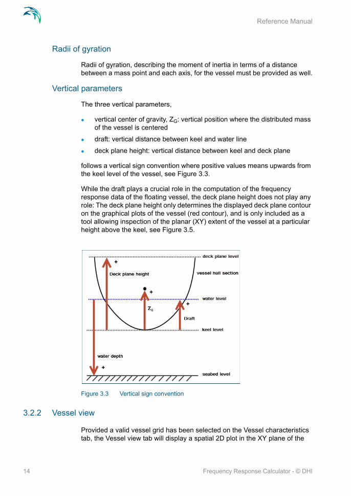
The three vertical parameters,
vertical center of gravity, ZG: vertical position where the distributed mass of the vessel is centered
draft: vertical distance between keel and water line
deck plane height: vertical distance between keel and deck plane
follows a vertical sign convention where positive values means upwards from the keel level of the vessel, see Figure 3.3.
While the draft plays a crucial role in the computation of the frequency response data of the floating vessel, the deck plane height does not play any role: The deck plane height only determines the displayed deck plane contour on the graphical plots of the vessel (red contour), and is only included as a tool allowing inspection of the planar (XY) extent of the vessel at a particular height above the keel, see Figure 3.5.
Figure 3.3 Vertical sign convention
3.2.2 Vessel view
Provided a valid vessel grid has been selected on the Vessel characteristics tab, the Vessel view tab will display a spatial 2D plot in the XY plane of the
14 Frequency Response Calculator - © DHI

Vessel Instance
water line contour around the vessel (due to draft), as well as the deck plane contour (due to deck plane height). A definition of the two planes is given in Figure 3.4.
Figure 3.4 Definition of waterline and deck plane contour
The purpose of the plot under Vessel view is give an insight into what the spa-tial picture looks like, where these two contours are relative to each other., as shown in Figure 3.5.
Figure 3.5 Displaying vessel Red polygon: Deck plane contour as defined by the deck plane height.Filled polygon: Submerged contour as defined by the draft.
The origo in this contour plot will by default be positioned at the amidship point of the vessel.
Just like the Vessel statistics values on the Vessel characteristics tab, the contour plot will respond to changes in draft (water line contour will be updated) and deck plane height (deck plane contour will be updated) as well as the scaling parameters (both contours will be updated). The user can assess if it looks meaningful, and change the draft and deck plane height, if assessed needed.
15
Reference Manual
NOTE: Advanced interactive features like Pan and Mouse Wheel based zoom, are available for the most flexible work flow, e.g. when certain details are to be looked up and inspected. These two features become active when you click on the plot and hold down the shift key on the keyboard.
3.3 Computational Settings
Here you specify the Simulation mode:
M21 Mooring Analysis compatible mode
User defined mode
M21 Mooring Analysis compatible modeThis is the default simulation mode. This mode should be used if the overall aim is to proceed with a vessel motion analysis in the time-domain, with MIKE 21 MA. Execution in this mode will create a (.vre) output file bundling all rele-vant geometric and frequency response output data, which is later to be loaded into MIKE 21 MA for further processing. Due to compatibility require-ments the only freedom you have in this mode, is to decide the number of fre-quencies to be solved for, either 256 or 512. Notice that when running the FRC simulation in this mode two extra frequencies (zero and infinity) are always implicitly included, meaning that an additional 2 frequencies are taken into account. The frequency range, and the directional range are pre-defined in this mode.
User defined modeThis mode is used if you want to perform independent analyses with FRC, e.g. analyze RAOs. RAOs help determining the vessel’s response subject to recurring load cycles, e.g. waves. In this mode, FRC can be used to investi-gate the vessel’s response for a particular number of specified frequencies, in a certain frequency range, in a certain directional range. Figure 3.6 depicts the horizontal directional sign convention in FRC, which is similar to the OCIMF Guidelines /4/. Execution in this mode won't generate a (.vre) file which can be used as a basis for further time-domain behaviour of a vessel.
16 Frequency Response Calculator - © DHI

Wave Drift Forces
Figure 3.6 The FRC directional range sign convention (same as OCIMF guidelines /4/)
3.4 Wave Drift Forces
Here you can specify whether you want to include the physical phenomenon of 2nd order wave drift forces. The 2nd order wave drift forces are based on the Newman’s approximation /3/ which is only valid in deep water.
NOTE:Including wave drift forces will lead to a more time consuming overall FRC simulation (20-30 % extra for typical applications). The wave drift forces are negligible at high wave periods. So an example where it is not recommended to include wave drift forces is for a passing vessel scenario, where you just have one high period wave. It should thus always be assessed whether it is required to include wave drift forces.
3.5 Outputs
The selection of potential output files includes:
Vessel response
Added mass
Damping
Drift forces
Response amplitude operator
Exciting forces
17
Reference Manual
3.5.1 Vessel response
This is a special file of type (.vre) which stores a lot of different bundled output data (geometric and frequency response data). When generated, this file is binary and cannot be inspected for content with any editor. The only applica-tion of this file is that it is the input file in order to use MIKE 21 MA for time-domain analysis of the defined vessel when exposed to environmental forc-ings and moored. This file is only possible to generate if Simulation mode is set to M21 Mooring Analysis compatible mode, in the Computational Settings section.
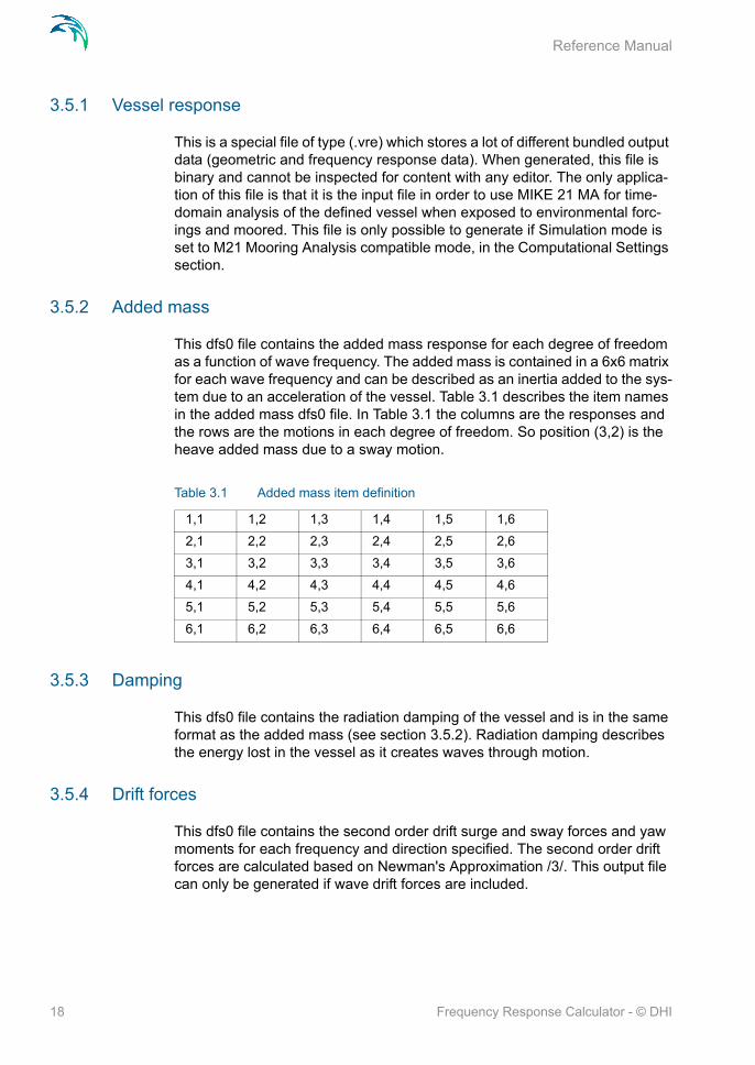
3.5.2 Added mass
This dfs0 file contains the added mass response for each degree of freedom as a function of wave frequency. The added mass is contained in a 6x6 matrix for each wave frequency and can be described as an inertia added to the sys-tem due to an acceleration of the vessel. Table 3.1 describes the item names in the added mass dfs0 file. In Table 3.1 the columns are the responses and the rows are the motions in each degree of freedom. So position (3,2) is the heave added mass due to a sway motion.
3.5.3 Damping
This dfs0 file contains the radiation damping of the vessel and is in the same format as the added mass (see section 3.5.2). Radiation damping describes the energy lost in the vessel as it creates waves through motion.
3.5.4 Drift forces
This dfs0 file contains the second order drift surge and sway forces and yaw moments for each frequency and direction specified. The second order drift forces are calculated based on Newman's Approximation /3/. This output file can only be generated if wave drift forces are included.
Table 3.1 Added mass item definition
1,1 1,2 1,3 1,4 1,5 1,6
2,1 2,2 2,3 2,4 2,5 2,6
3,1 3,2 3,3 3,4 3,5 3,6
4,1 4,2 4,3 4,4 4,5 4,6
5,1 5,2 5,3 5,4 5,5 5,6
6,1 6,2 6,3 6,4 6,5 6,6
18 Frequency Response Calculator - © DHI
Outputs
3.5.5 Response amplitude operator
This dfs0 file contains the amplitude and phase data of the response ampli-tude operator (RAO) for each frequency and direction specified. The RAO is a transfer function that can be used to determine the effect that a sea state will have upon the motion of a vessel.
A separate file can be generated for each vessel in the simulation.
3.5.6 Exciting forces
This dfs0 file contains the amplitude and phase data of the exciting forces and moments for each frequency and direction specified. The exciting force is the first order wave force on the vessel and is calculated using the Haskind relation (see e.g. /2/). The exciting force describes the combination of the incident wave forces from a harmonic wave and the diffraction force due to the vessel on the undisturbed wave field.
A separate file can be generated for each vessel in the simulation.
19

Reference Manual
20 Frequency Response Calculator - © DHI

Outputs
4 References
/1/ Christensen, E.D., Jensen, B., Mortensen, S., Hansen, H.F. and Kir-kegaard J. (2008). “Numerical Simulation of Ship Motion in Offshore and Harbour Areas”, OMAE2008-57206, Proc. ASME 27th Int. Conf. on Offshore Mechanics and Arctic Engineering, Estoril, Portu-gal
/2/ Wehausen, J.V. and Laitone, E.V. (1960): “Surface Waves in Fluid Dynamics III”, in Handbuch der Physik 9, Eds: S. Fluegge and C.Truesdell, pp 446-778, Springer Verlag
/3/ Newman, J.N. (1974) “Second-Order, Slowly Varying Forces on Vessels in Irregular Waves”, Proc., Int. Symp. On Dynamics of Marine Vehicles and Structures in Waves, London, UK
/4/ OCIMF (2008). “Mooring Equioment Guidelines”, 3rd edition, With-erby Seamanship International, Livingston, UK
21

References
22 Frequency Response Calculator - © DHI

INDEX
23

Index
Symbols.grd . . . . . . . . . . . . . . . . . 12.hull . . . . . . . . . . . . . . . . . 13
AAdded mass . . . . . . . . . .9, 10, 18
BBeam . . . . . . . . . . . . . . . . 11
DDeck plane height . . . . . . . . . . 14Draft . . . . . . . . . . . . . . . 11, 14Drift forces . . . . . . . . . . . . . . 18
EExciting forces . . . . . . . . . . 10, 19
GGyration . . . . . . . . . . . . . . . 14
HHeight . . . . . . . . . . . . . . . . 11
LLength Over All . . . . . . . . . . . 11
MM21 Mooring Analysis compatible mode16
RRadiation damping . . . . . . . . 10, 18Radiation potentials . . . . . . . . . 10Radii of gyration . . . . . . . . . . . 14RAOs . . . . . . . . . . . . . . 10, 16Response amplitude operator . . . . 19Response Amplitude Operators . . . .9
SScaling . . . . . . . . . . . . . . . . 13Submerged volume . . . . . . . . . 11
UUser defined mode . . . . . . . . . 16
Vvertical center of gravity . . . . . . .14Vessel grid . . . . . . . . . . . . . . 11
WWater depth . . . . . . . . . . . . . 11Wave drift forces . . . . . . . . .10, 17
24 Frequency Response Calculator - © DHI


![PRESSURE VESSEL [Proses Pembuatan Pressure Vessel]](https://img.pdfslide.net/doc/110x75/546b26fab4af9fc2128b4e24/pressure-vessel-proses-pembuatan-pressure-vessel.jpg)