Embed Size (px)
Citation preview


I want to express my thanks to you for being interested in our products and for having
confidence in MikroElektronika.
The primary aim of our company is to design and produce high quality electronic products
and to constantly improve the performance thereof in order to better suit your needs.
TO OUR VALUED CUSTOMERS
Nebojsa Matic
General Manager
ARM® and Windows® logos and product names are trademarks of ARM® Holdings and Microsoft® in the U.S.A. and other countries.

Page 3
1. Introduction to mikroC PRO for ARM® . . . . . . . . . . . . . . . . . . . . . . . . . . . . . . . . . . . . . . . . 04
2. Hardware connection . . . . . . . . . . . . . . . . . . . . . . . . . . . . . . . . . . . . . . . . . . . . . . . . . . . . . . . 05
3. Creating a new project . . . . . . . . . . . . . . . . . . . . . . . . . . . . . . . . . . . . . . . . . . . . . . . . . . . . . 06
Step 1 - Project settings . . . . . . . . . . . . . . . . . . . . . . . . . . . . . . . . . . . . . . . . . . . . . . . . 07
Step2-Addfiles...................................................... 10
Step 3 - Include libraries . . . . . . . . . . . . . . . . . . . . . . . . . . . . . . . . . . . . . . . . . . . . . . . . 11
Step 4 - Finishing . . . . . . . . . . . . . . . . . . . . . . . . . . . . . . . . . . . . . . . . . . . . . . . . . . . . . . 12
Blank new project created . . . . . . . . . . . . . . . . . . . . . . . . . . . . . . . . . . . . . . . . . . . . . . . 13
4. Code example . . . . . . . . . . . . . . . . . . . . . . . . . . . . . . . . . . . . . . . . . . . . . . . . . . . . . . . . . . . . . . 14
5. Building the source . . . . . . . . . . . . . . . . . . . . . . . . . . . . . . . . . . . . . . . . . . . . . . . . . . . . . . . . . 16
6. Changing project settings . . . . . . . . . . . . . . . . . . . . . . . . . . . . . . . . . . . . . . . . . . . . . . . . . . . 17
7. What’s next . . . . . . . . . . . . . . . . . . . . . . . . . . . . . . . . . . . . . . . . . . . . . . . . . . . . . . . . . . . . . . . . 18
Table of Contents

Page 4
mikroC PRO for ARM® organizes applications
into projects consisting of a single project file
(file with the .mcpar extension) and one or
more source files (files with the .c extension).
The mikroC PRO for ARM® compiler allows you to
manage several projects at a time. Source files
can be compiled only if they are part of a project.
In this reference guide, we will create a new project,
write code, compile it and test the results. The
purpose of this project is to make microcontroller
PORTA LEDs blink, which will be easy to test.
Aprojectfilecontains:
• Project name and optional description;
• Target device in use;
• Device clock;
•Listofprojectsourcefiles;
•Binaryfiles(*.emcl);and
•Otherfiles.
1. Introduction to mikroC PRO for ARM®
03
04
05
06
07
08
01
02
Main Toolbar
Code Explorer
Project Settings
Messages
Code Editor
Image Preview
05
06
0703
02
04
01
08
Project Manger
Library Manager

Page 5
Let’s make a simple “Hello world” example for the
selected microcontroller. First thing embedded
programmers usually write is a simple LED blinking
program. So, let’s do that in a few simple lines of C code.
LED blinking is just turning ON and OFF LEDs that are
connected to desired PORT pins. In order to see the
example in action, it is necessary to connect the target
microcontroller according to schematics shown on
Figure 2-1. In the project we are about to write, we
will use only PORTA, so you should connect the LEDs
to PORTA only.
Priortocreatinganewproject,itisnecessarytodothefollowing:
Step 1: Install the compilerInstall mikroC PRO for ARM® from the Product DVD or download it
fromtheMikroElektronikawebsite:
Step 2: Start up the compilerDouble click on the compiler icon in the Start menu, or on your
desktop to Start up mikroC PRO for ARM®. The mikroC PRO for ARM®
IDE (Integrated Development Environment) will appear on the
screen. Now you are ready to start creating a new project.
2. Hardware connectionVCC-3.3
AVCC
30292827 3433
58575655545352
463635 42 43 44 4537 50
9
48 49
1112
32
72
69686766656463
43
78 77
2423
181716151413
5678
10
7980
12
22212019
62616059
38 39 40 41 47
71
31
51
70
26
25
76
757473
LM3S9B95
81828384858687888990919293949596979899100
PA
7P
A6
ER
BIA
SV
DD
PF4
PF5
PE5PE4LDOVDD
GNDVDD
PB1/USB0VBUS
VDD
VD
DTX
OP
PJ4PJ5PJ6PJ7
GN
DTX
ON
PB
5P
B6
PB
7
VD
D
VD
DC
PJ1
PH
2P
H3
GNDAVDDA
PD
5P
D4
PE
3P
E2
GN
D
PB
4
PD2
PA
2
PC6PC7GNDVDDPG0PG1
USB0DPUSB0DM
NC
PB3/I2C0SDA
PJ0
PD1PD0
VD
DC
PD
6P
D7
PE7PE6
PA
1P
A0
PC4PC5
OS
C1
PJ3
PB0/USB0ID
PF2
PF0
OS
C0
GND
PJ2
RX
IN
MDIO
PF1
PH
0
XTALNPHYXTALPPHYPH7
PG
7
RX
IP
PF3
RST
PH
1
PA
5P
A4
PA
3
PA
7P
A6
PA
2P
A1
PA
0
PA
5P
A4
PA
7
PA
6
PA
5
PA
4
PA
3
PA
2
PA
1
PA
0
PA
3
PD3
GND
PH6PH5
PB2/I2C0SCL
PC
2
PH
4
USB0BIASPE0PE1
PC
3
PC
1P
C0
VD
DG
ND
U1
R619K1
E910uF
VCORE
VCORE
R14K7
R5
4K7
R24K7
R6
4K7
R34K7
R7
4K7
R44K7
R8
4K7
LD0LED
LD4LED
LD1LED
LD5LED
LD2LED
LD6LED
LD3LED
LD7LED
VCC3
VCC3
Figure 2-1: Hardware connection schematic
http://www.mikroe.com/mikroc/arm/

Page 6
The process of creating a new project is
very simple. Select the New Project option
from the Project menu as shown below.
The New Project Wizard window appears.
It can also be opened by clicking the New Project icon from the Project toolbar.
The New Project Wizard (Figure 3-1) will
guide you through the process of creating
a new project. The introductory window of
this application contains a list of actions to
be performed when creating a new project.
3. Creating a new project
Figure 3-1: Introductory window of the New Project Wizard
01
Click Next.01

Page 7
First thing we have to do is to specify the
general project information. This is done
by selecting the target microcontroller, its
operating clock frequency, and of course
- naming our project. This is an important
step, because the compiler will adjust the
internal settings based on this information.
Defaultconfigurationisalreadysuggested
to us at the begining. We will not change
the microcontroller, and we will leave the
default LM3S9B95 as the choice for this
project.
Step 1 - Project settings
Figure 3-2: You can specify project name, path, device and clock in the first step

Page 8
If you do not want to use the suggested
path for storing your new project, you can
change the destination folder. In order
todothat,followasimpleprocedure:
Step 1 - Project settings
Figure 3-3: Change the destination folder using Browse For Folder dialog
01
01
02
03 03
02
Click the Browse button of the Project
Settings window to open the Browse for Folder dialog.
Select the desired folder to be the
destination path for storing your new
projectfiles.
Click the OK button to confirmyour
selection and apply the new path.

Page 9
Once we have selected the destination
project folder, let’s do the rest of the project
settings:
Step 1 - Project settings
Figure 3-4: Enter project name and change device clock speed if necessary
01
02
03
03
01
02
Enter the name of your project. Since
we are going to blink some LEDs,
it’s appropriate to call the project
“LedBlinking”
For this demonstration, we will use
the default 16MHz clock. Clock speed
depends on your target hardware, and
whether you are using PLL or not. But
howeveryouconfigureyourhardware,
make sure to specify the exact clock
(Fosc) that the microcontroller is
operating at.
Click the OK button to proceed.

Page 10
This step allows you to include additional
files thatyouneed inyourproject: some
headers or source files that you already
wrote, and that you might need in further
development. Since we are building a
simple application, we won’t be adding any
filesatthismoment.
Step 2 - Add files
01
Figure 3-5: Add existing headers, sources or other files if necessary
Click Next.01

Page 11
Following step allows you to quickly set
whether you want to include all libraries
in your project, or not. Even if all libraries
are included, they will not consume
any memory unless they are explicitely
used from within your code. The main
advantage of including all libraries is that
you will have over 500 functions available
for use in your code right away, and visible
from Code Assistant [CTRL+Space]. We
willleavethisindefaultconfiguration:
Step 3 - Include libraries
02
01
Figure 3-6: Include all libraries in the project, which is a default configuration.
01
02
Make sure to leave “Include All” selected.
Click Next.

Page 12
After all the configuration is done, the
finalstepallowsyoutodojustabitmore.
Step 4 - Finishing
Figure 3-7: Choose whether to open Edit Project window after dialog closes.
02
0101 There is a check-box called “Open Edit Project window to set Configuration bits”atthefinalstep.Edit Project is a
specialized window which allows you to
do all the necessary oscillator and PLL
settings. We made sure that everything
is described in plain English, so you
will be able to do the settings without
having to open the datasheet. Anyway,
since we are only building a simple
application, we will leave it at default
configuration(internal16MHzoscillator
with PLL disabled). Therefore, leave the checkbox unchecked.
Click Finish.02

Page 13
New project is finally created. A new
source file called “LedBlinking.c” is
created and it contains the void main()
function, which will hold the program.
Youmaynoticethatproject isconfigured
according to the settings done in the New Project Wizard.
Blank new project created
Figure 3-8: New blank project is created with your configuration

Page 14
Time has come to do some coding. mikroC
PRO for ARM® has the unique libraries that
enable you to do complicated tasks in a
single line of code. Built-in GPIO library
enables you to set configure each PORT
and enable pins that you need, without
worrying about complex procedure that
this operation requires. To demonstrate
this,wewillwriteourfirstlineofcode:
Once we have enabled PORTA to act as
digital output, we can now initialize PORTA
withlogiczerosoneveryPORTpin:
Finally, in a while() loop we will toggle the
PORTA value, and put a 1000 ms delay, so
the blinking is not too fast.
void main() {
// Set PORTA as digital output GPIO_Digital_Output(&GPIO_PORTA, _GPIO_PINMASK_ALL); // Set PORTA initial value to zero GPIO_PORTA_DATA = 0; while(1) { // Toggle PORTA GPIO_PORTA_DATA = ~GPIO_PORTA_DATA; // Delay 1000 ms Delay_ms(1000); }
}
// Set PORTA as digital outputGPIO_Digital_Output( &GPIO_PORTA, _GPIO_PINMASK_ALL);
// Set PORTA initial value to 0GPIO_PORTA_DATA = 0;
123456789101112131415161718
LedBlinking.c - source code
4. Code example
Figure 4-1: Complete source code of the PORTA LED blinking

Page 15
Figure 4-2: This is how the code looks written in compiler code editor window

Page 16
Whenwearedonewritingourfirst
LedBlinking code, we can now build
the project and create a .HEX filewhich can be loaded into our target
microcontroller, so we can test the
program on real hardware. “Building”
includes compilation, linking and
optimization which is all done automatically. Build your code by clicking
on the icon in the main toolbar, or simply go to Build menu and
click Build [CTRL+F9]. Message window will report the details of
the building process (Figure 5-2). Compiler automatically creates
necessaryoutputfiles.LedBlinking.hex (Figure 5-1) is among them.
5. Building the source
Figure 5-1: Listing of project files after building is done
Figure 5-2: After the successful compilation and linking, the message window should look something like this

Page 17
If you need to change the target microcontroller or clock speed, you don’t have to go through the new project wizard all over again. This
can be done quickly in the Edit Project window. You can open it using Project->Edit Project [CTRL+SHIFT+E] menu option.
6. Changing project settings
Figure 6-1: Edit Project Window
01
02
03
04
To change your MCU, just select the desired microcontroller from the dropdown list.
To change your oscillator settings enter the oscillator value and adjust oscillatorconfigurationregistersus-ing drop-down boxes.
Several most commonly used oscil-lator settings can be loaded using the provided oscillator “schemes”. Load the desired scheme by clicking the Load Scheme button.
Select whether to build a Debug HEX, which is necessary for hardware debugging,orafinalRelease HEX.
01
02
02
03
03
Page 18
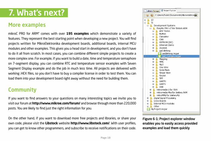
mikroC PRO for ARM® comes with over 195 examples which demonstrate a variety of
features.Theyrepresentthebeststartingpointwhendevelopinganewproject.Youwillfind
projects written for MikroElektronika development boards, additional boards, internal MCU
modules and other examples. This gives you a head start in development, and you don’t have
todoitallfromscratch.Inmostcases,youcancombinedifferentsimpleprojectstocreatea
more complex one. For example, if you want to build a date, time and temperature semaphore
on 7-segment display, you can combine RTC and temperature sensor examples with Seven
Segment Display example and do the job in much less time. All projects are delivered with
working.HEXfiles,soyoudon’thavetobuyacompilerlicenseinordertotestthem.Youcan
load them into your development board right away without the need for building them.
Figure 6-1: Project explorer window enables you to easily access provided examples and load them quickly
7. What’s next?
Ifyouwanttofindanswerstoyourquestionsonmanyinterestingtopicsweinviteyouto
visit our forum at http://www.mikroe.com/forum/ and browse through more than 220,000
posts.Youarelikelytofindjusttherightinformationforyou.
On the other hand, if you want to download more free projects and libraries, or share your
own code, please visit the Libstock website http://www.libstock.com/.Withuserprofiles,
youcangettoknowotherprogrammers,andsubscribetoreceivenotificationsontheircode.
Community
More examples

DISCLAIMER
All the products owned by MikroElektronika are protected by copyright law and international copyright treaty. Therefore, this manual is to be treated as any other copyright material. No part of this manual, including product and software described herein, may be reproduced, stored in a retrieval system, translated or transmitted in any form or by any means, without the prior written permission of MikroElektronika. The manual PDF edition can be printed for private or local use, butnotfordistribution.Anymodificationofthismanualisprohibited.
MikroElektronika provides this manual ‘as is’ without warranty of any kind, either expressed or implied, including, but not limited to, the implied warranties or conditionsofmerchantabilityorfitnessforaparticularpurpose.
MikroElektronika shall assume no responsibility or liability for any errors, omissions and inaccuracies that may appear in this manual. In no event shall MikroElektronika,itsdirectors,officers,employeesordistributorsbeliableforanyindirect,specific,incidentalorconsequentialdamages(includingdamagesforlossofbusinessprofitsandbusinessinformation,businessinterruptionoranyotherpecuniaryloss)arisingoutoftheuseofthismanualorproduct,evenifMikroElektronika has been advised of the possibility of such damages. MikroElektronika reserves the right to change information contained in this manual at any time without prior notice, if necessary.
TRADEMARKS
The MikroElektronika name and logo, mikroC™, mikroProg™, mikroBUS™, click™ boards, EasyMx PRO™ and mikromedia™ are trademarks of MikroElektronika. All other trademarks mentioned herein are property of their respective companies.All other product and corporate names appearing in this manual may or may not be registered trademarks or copyrights of their respective companies, and are only usedforidentificationorexplanationandtotheowners’benefit,withnointenttoinfringe.
Copyright © 2014 MikroElektronika. All Rights Reserved.
HIGH RISK ACTIVITIES
The products of MikroElektronika are not fault – tolerant nor designed, manufactured or intended for use or resale as on – line control equipment in hazardous environments requiring fail – safe performance, such as in the operation of nuclear facilities, aircraft navigation or communication systems, airtrafficcontrol,directlifesupportmachinesorweaponssystemsinwhichthefailureofSoftwarecouldleaddirectlytodeath,personalinjuryorseverephysicalorenvironmentaldamage (‘HighRiskActivities’).MikroElektronikaand itssuppliersspecificallydisclaimanyexpressedor impliedwarrantyoffitnessforHighRiskActivities.

If you want to learn more about our products, please
visit our website at www.mikroe.com. If you are
experiencing some problems with any of our products or
just need additional information, please place your ticket
at www.mikroe.com/support If you have any questions,
comments or business proposals, do not hesitate to
contact us at [email protected]
Designed by MikroElektronika Ltd.www.mikroe.com
Creating the first projectin mikroC PRO for ARM
ver. 1.00a
0 100000 026366


![Creating first project in mikroC PRO for ARM [2.63MB]ubiquitics.co.kr/.../get/1767/ctfp_mikroc_pro_for_arm.pdf · · 2012-05-01Page 2 Page 3 mikroC PRO for ARM® organizes applications](https://img.pdfslide.net/doc/110x75/5af439857f8b9a5b1e8c3b95/creating-first-project-in-mikroc-pro-for-arm-263mb-2-page-3-mikroc-pro-for-arm.jpg)