Embed Size (px)
Citation preview

PUBLISHED BY DIRECTION OF COMMANDER, NEW YORK NAVAL MILITIA
MILBOATSTECHMAN/BK-04
VERSION 3
MILITARY EMERGENCY BOAT SERVICE
TECHNICAL MANUAL BOOK 04
PATROL BOAT 300 CLASS
DISTRIBUTION STATEMENT: APPROVED FOR PUBLIC RELEASE, DISTRIBUTION IS UNLIMITED.
5 APRIL 2016

22 APR 2016
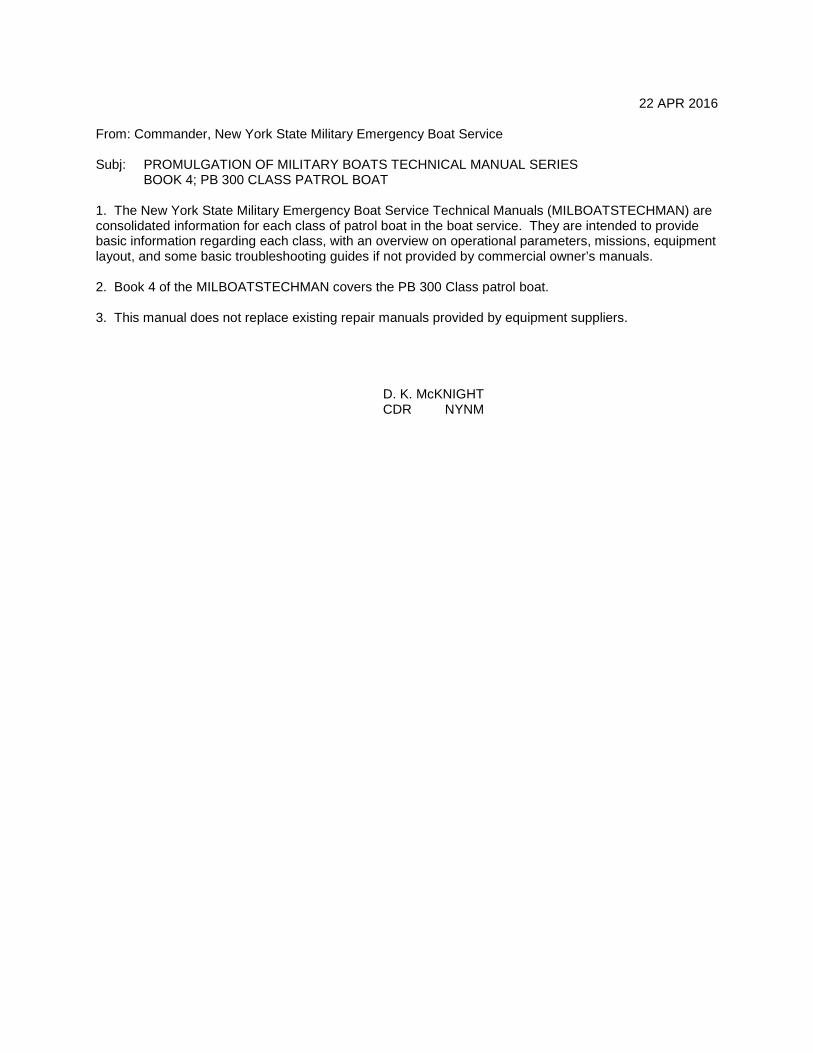
From: Commander, New York State Military Emergency Boat Service Subj: PROMULGATION OF MILITARY BOATS TECHNICAL MANUAL SERIES BOOK 4; PB 300 CLASS PATROL BOAT 1. The New York State Military Emergency Boat Service Technical Manuals (MILBOATSTECHMAN) are consolidated information for each class of patrol boat in the boat service. They are intended to provide basic information regarding each class, with an overview on operational parameters, missions, equipment layout, and some basic troubleshooting guides if not provided by commercial owner’s manuals. 2. Book 4 of the MILBOATSTECHMAN covers the PB 300 Class patrol boat. 3. This manual does not replace existing repair manuals provided by equipment suppliers. D. K. McKNIGHT CDR NYNM

MILBOATSTECHMAN/BK-04 PB 300 CLASS
2
This Page Intentionally Left Blank

MILBOATSTECHMAN/BK-04 PB 300 CLASS
3
PB 301 underway Hudson River

MILBOATSTECHMAN/BK-04 PB 300 CLASS
4
This Page Intentionally Left Blank
MILBOATSTECHMAN/BK-04 PB 300 CLASS
5
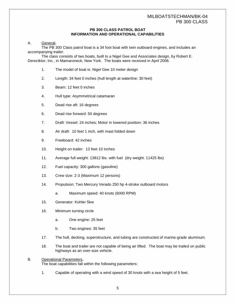
PB 300 CLASS PATROL BOAT INFORMATION AND OPERATIONAL CAPABILITIES
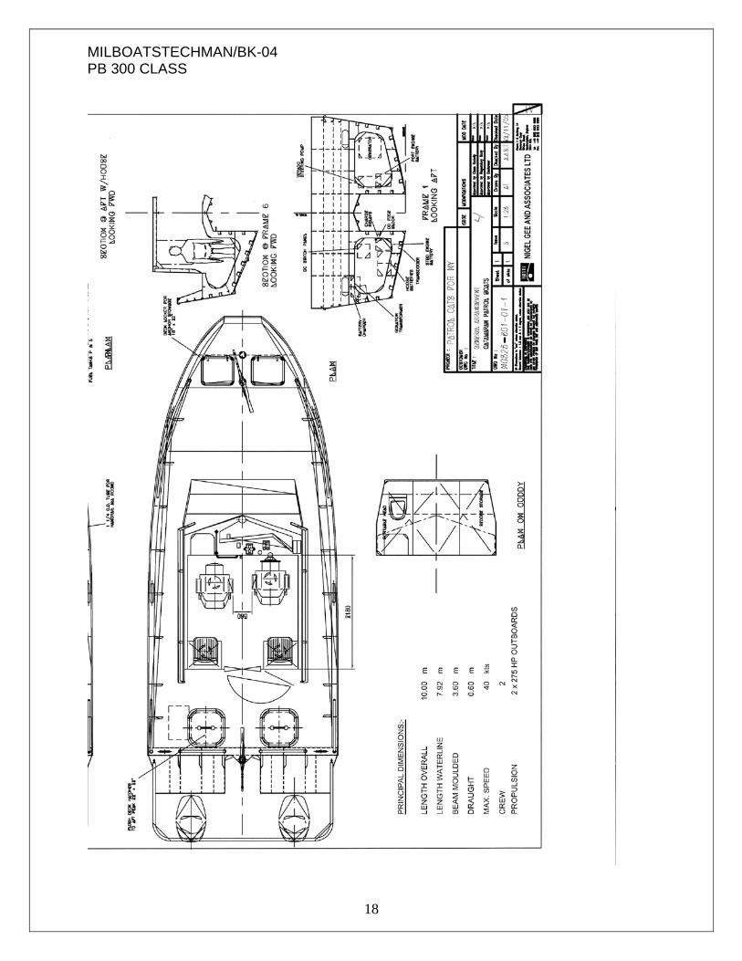
A. General. The PB 300 Class patrol boat is a 34 foot boat with twin outboard engines, and includes an accompanying trailer. The class consists of two boats, built to a Nigel Gee and Associates design, by Robert E. Derectktor, Inc., in Mamaroneck, New York. The boats were received in April 2006. 1. The model of boat is: Nigel Gee 10 meter design 2. Length: 34 feet 0 inches (hull length at waterline: 30 feet) 3. Beam: 12 feet 0 inches 4. Hull type: Asymmetrical catamaran 5. Dead rise aft: 16 degrees 6. Dead rise forward: 50 degrees 7. Draft: Vessel: 24 inches; Motor in lowered position: 36 inches 8. Air draft: 10 feet 1 inch, with mast folded down 9. Freeboard: 42 inches 10. Height on trailer: 13 feet 10 inches 11. Average full weight: 13812 lbs. with fuel (dry weight: 11425 lbs) 12. Fuel capacity: 300 gallons (gasoline) 13. Crew size: 2-3 (Maximum 12 persons) 14. Propulsion: Two Mercury Verado 250 hp 4-stroke outboard motors a. Maximum speed: 40 knots (6000 RPM) 15. Generator: Kohler 5kw 16. Minimum turning circle a. One engine: 25 feet b. Two engines: 35 feet 17. The hull, decking, superstructure, and tubing are constructed of marine-grade aluminum.
18. The boat and trailer are not capable of being air lifted. The boat may be trailed on public
highways as an over-size vehicle. B. Operational Parameters. The boat capabilities fall within the following parameters: 1. Capable of operating with a wind speed of 30 knots with a sea height of 5 feet.

MILBOATSTECHMAN/BK-04 PB 300 CLASS
6
2. Capable of surviving with a wind speed of 50 knots with a sea height of 7 feet. 3. Capable of operating in air temperatures of 0 – 100 degrees Fahrenheit. 4. Capable of operating in water temperatures of 28 – 95 degrees Fahrenheit. C. Missions. The boat is capable of several missions. With an enclosed and heated cabin, it is suitable for year-round operations. The boat is capable of operating in all waters in or contiguous to New York State. With an asymmetrical catamaran hull, it is a stable platform well-suited to operate in rough waters. For the purposes of NYNM, the primary mission is maritime patrol. D. Features. The boat includes the following features and components: 1. Hull: a. Aluminum construction, with ¼-inch bottom plate, and 3/16-inch side plate. b. Asymmetrical catamaran hull
c. Welded aluminum bow, stern, roof, and aft cabin rails
d. Towing bracket 2. Deck: a. Aluminum b. Self bailing scuppers c. (6) 10-inch welded cleats d. 4-inch aluminum tow post e. Hatches (2) aft, (1) cabin, (2) bow f. Bow locker for anchor storage 3. Cabin: a. Forward leaning windshield with ¼-inch clear, tempered glass-Pilkington b. Sliding ¼-inch side windows c. Windshield wipers (2 speed) (2) d. Air conditioner - SeaMach (Coleman) e. Un-finished cuddy cabin forward with porta-john, and cuddy cabin hatch to bow f. Overhead and dash grab rails

MILBOATSTECHMAN/BK-04 PB 300 CLASS
7
g. Heater, electric 1500 watt –Heater Craft Dial-a-Watt h. Heater, diesel WEBASTO 2000STC with 1-gallon fuel tank. h. 4 seats i. Carbon monoxide detector-Xintex j. Fold-down mast 4. Engines: a. Twin outboards; 250 hp Mercury Verado, counter rotating 6 cylinder, 4-stroke, 158.5 cu in displacement, each motor (1) Idle speed: 550 rpm (3 knots) (2) Cruise speed: 3100 rpm (11 knots) (3) Full speed: 5800-6400 rpm (35+ knots) (4) On plane: 4300 rpm (5) Off plane: 4000 rpm
(6) Ref: Mercury Marine Manual 90-8M0087585, Outboard Operation, Maintenance & Warranty Manual; 200/225/250/275 Verado [4-Stroke] Manual
(7) Original outboard engines were replaced in March 2014
5. Generator: a. One Kohler 5KW; Model 5E, 60Hz (gasoline powered) 2 cylinder, 4-stroke Kawasaki engine (model FD501D) (1) Aluminum head and cylinder block
(2) Fuel consumption: 0.76 gallons per hour at full load (3) Located in port lazarette
(4) Ref: Kohler Power Systems publications TP-5982, G2-58, and TP-5982,
G2-58, and TT-687 6. Steering: a. Helm wheel 7. Fuel system:
a. 300 gallons (150 gallon tanks port and starboard)
b. Fuel tank fills port and starboard abaft beam 8. Electrical system:

MILBOATSTECHMAN/BK-04 PB 300 CLASS
8
a. 12VDC system with three batteries (port, starboard, house)
b. Electronic battery charger - Charles 2000SP series c. 12 breaker panel-Blue Sea Systems
d. Bilge pump - Rule-Mate 2000 GPH
e. Shore power connection: 25-foot, 30amp, 125 volt, 2 pole, 3 wire yellow 10AWG f. 12 VDC outlets (2) on dash
g. 115 VAC outlets (2) under rear seats
9. Lighting: a. Navigation/anchor lights - Aqua Signal Series 25 b. Dual blue strobe lights on roof -Galls model 1000 c. Spotlight 5-inch - Jabsco d. Interior fluorescent and LED lighting including red night lights 10. Navigation and electronics: a. Radar - Furuno Model 1724 with NAVnet (1) Ref: Furuno Electric Co Pub. No. OSE-35550-A b. Global Positioning System chart plotter - Furuno Model GP1650WF c. Binnacle compass - Ritchie Helmsman HF743 d. Marine VHF Radios (2), with hailer - Standard Horizon Quantum GX5500S e. Kenwood TK 690/790 dual-band VHF Radios f. L3 Communications ProTec Automatic Identification System (AIS) Encrypted g. Long Range Acoustic Device (LRAD) Model 300 (shared asset) 11. Gauges: a. Mercury SmartCraft (1) Ref: Mercury Marine 90-10229023 203 b. Fuel gauge 12. Ground tackle: a. Anchor, 20 lbs Bruce type; 10 feet of chain and 150 5/8-inch anchor line 13. Safety equipment:

MILBOATSTECHMAN/BK-04 PB 300 CLASS
9
a. Fire extinguisher – 10 lb., ABC b. PDFs (Type 1) c. Emergency flare kit d. Ring buoy with light e. Air horns, dual trumpet - Fultone II f. Portable rescue ladder 14. Trailer: a. Tri-axle trailer - Magic Tilt Model TTALS 34110B3 aluminum
b. GVWR: 14050 lbs c. 12,700 lb capacity
d. Trailer weight: 1650 lbs e. Electric winch, mechanical brakes, spare tire
f. Trailer is 42 feet 6 inches in length when combined with boat.
g. Trailer dimensions: 36 feet 8 inches long, 8 feet 7 inches wide. E. WEBASTO heater startup procedures:
1. Turn on lower defroster breaker 2. Hit selection button. The time set screen will come up. 3. Press button until the Temperature screen comes up. 4. Press the on/off button once and the heater will ignight. Two red lights will
illuminate on either side of the temperature indicated. Hit button once to shut off. 5. Turn the rotary knob clockwise or counter clockwise to set desired temperature
and push the selection button F. General Maintenance Requirements.
1. Mercury Verado Outboard Engines:
a. Outboard Care. To keep the outboard engines in the best operating condition, it is important that they receive the periodic inspections and maintenance listed in the Inspection and Maintenance Schedule.
b. Record maintenance performed in the Maintenance Log. Save all maintenance work
orders and receipts.
c. The manufacturer recommends using original Mercury Precision or Quicksilver replacement parts and Genuine Lubricants.

MILBOATSTECHMAN/BK-04 PB 300 CLASS
10
d. All new outboards manufactured by Mercury Marine are certified to the United States
Environmental Protection Agency, as conforming to the requirements of the regulations for the control of air pollution from new outboard motors. This certification is contingent on certain adjustments being set to factory standards. For this reason, the factory procedure for servicing the product must be strictly followed and, wherever practicable, returned to the original intent of the design. Maintenance, replacement, or repair of the emission control devices and systems may be performed by any marine spark ignition (SI) engine repair establishment or individual.
e. Inspection and Maintenance Schedule
(1) BEFORE EACH USE • Check engine oil level. See Fuel & Oil ‑ Checking and Adding
Engine Oil. • Check that lanyard stop switch stops the engine. • Visually inspect the fuel system for deterioration or leaks. • Check outboard for tightness on transom. • Check steering system for binding or loose components. • Visually check power steering fittings and hoses for leaks or signs of
damage. Check tie bar fasteners (multiple outboard rigs) for proper tightness.
• Check propeller blades for damage.
(2) AFTER EACH USE • Flush out the outboard cooling system if operating in salt or polluted
water. See Flushing the Cooling System. • Wash off all salt deposits and flush out the exhaust outlet of the
propeller and gearcase with fresh water if operating in salt water.
(3) EVERY 100 HOURS OF USE OR ONCE YEARLY, WHICHEVER OCCURS FIRST
• Change engine oil and replace the oil filter. The oil should be
changed more often when the engine is operated under adverse conditions such as extended trolling. See Changing Engine Oil.
• Inspect thermostat visually for corrosion and/or for a broken spring. Make sure thermostat closes completely at room temperature.
• Check engine water separating fuel filter for contaminants. Clean and/or replace filter. See Fuel System.
• Check corrosion control anodes. Check more frequently when used in salt water. See Corrosion Control Anodes.
• Drain and replace gearcase lubricant. See Gearcase Lubrication. • Check power steering fluid. See Checking Power Steering Fluid. • Inspect battery. See Battery Inspection. • Saltwater usage. Remove and inspect spark plugs for corrosion and
replace spark plugs as necessary. Apply a thin coating of Anti‑Seize Compound only on threads of spark plug prior to installation. See Maintenance ‑ Spark Plug Inspection and Replacement.
• Check wiring and connectors. • Check tightness of bolts, nuts, and other fasteners.
(4) EVERY 300 HOURS OF USE

MILBOATSTECHMAN/BK-04 PB 300 CLASS
11
IMPORTANT: Engine oil must be drained before removing gearcase to avoid oil spillage. Perform scheduled water pump replacement in combination with an engine oil change.
• Replace water pump impeller (more often if overheating occurs or reduced water pressure is noted).
• Check power trim fluid. See Checking Power Trim Fluid. • Replace high pressure in‑line fuel filter. • Replace spark plugs at first 300 hours or three years. After that,
inspect spark plugs every 300 hours or three years. Replace spark plugs as needed. See Spark Plug Inspection and Replacement.
• Replace accessory drive belt. See Accessory Drive Belt Inspection.
(5) BEFORE PERIODS OF STORAGE
• Refer to Storage procedure. See Storage section. Flushing The Cooling System Flush the internal water passages of the outboard with fresh water after each use in salt, polluted, or muddy water. This will help prevent a buildup of deposits from clogging the internal water passages.
NOTE: The outboard can be tilted or in the vertical operating position during flushing.
• With the engine turned off, place the outboard in either the operating position (vertical) or in a tilted position.
• Disconnect the flush connector from fitting on the bottom cowl. • Thread a water hose into the flush fitting.

MILBOATSTECHMAN/BK-04 PB 300 CLASS
12
• Turn on the water tap (1/2 maximum) and let the water flush
through the cooling system for about 15 minutes. • When flushing is complete, turn off water and disconnect the
water hose. • Reinstall the flushing connector to the fitting on the bottom cowl.
Tighten the connector securely.
f. Cowl Removal: Most maintenance points are accessible by removing the top cowl only.
• Pull up on the top cowl lock latch.
• 2. Pull top cowl forward and lift off. • 3. Pull lower cowl release latch up. • 4. Remove rear cowl towards aft of outboard.
g. Cowl Installation
• Position lower cowl from aft side of outboard. Make sure it fits properly in the rubber seal. • Lock cowl in place by pulling lower cowl latch down. • Place top cowl into position over engine, front first. Ensure cowl fits properly into the rubber seal. • The top cowl will lock into place when downward pressure is applied to the back side of cowl. Ensure cowl is securely fastened by pulling up on back of cowl.
h. Cleaning Care for Top and Bottom Cowls IMPORTANT: Dry wiping (wiping the plastic surface when it is dry) will result in minor surface scratches. Always wet the surface before cleaning. Do not use detergents containing hydrochloric acid. Follow the cleaning and waxing procedure.
• Before washing, rinse the cowls with clean water to remove dirt and dust that may scratch the surface. • Wash the cowls with clean water and a mild non‑abrasive soap. Use a soft clean cloth when washing. • Dry thoroughly with a soft clean cloth.
MILBOATSTECHMAN/BK-04 PB 300 CLASS
13
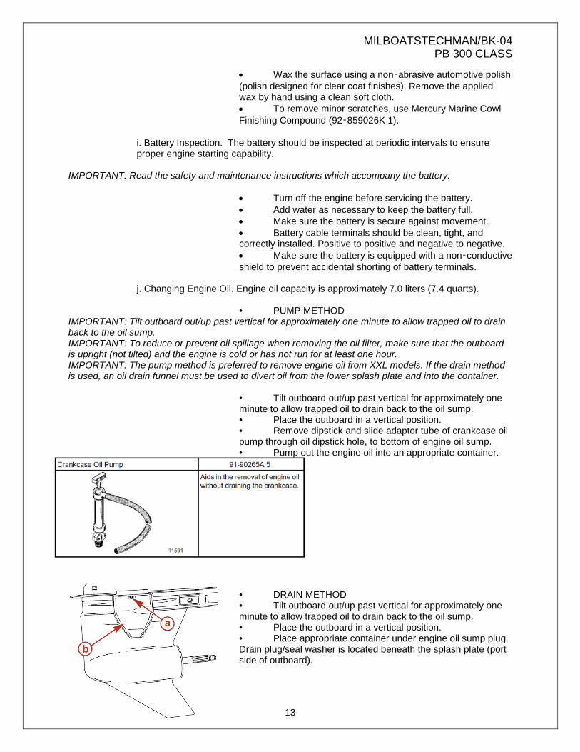
• Wax the surface using a non‑abrasive automotive polish (polish designed for clear coat finishes). Remove the applied wax by hand using a clean soft cloth. • To remove minor scratches, use Mercury Marine Cowl Finishing Compound (92‑859026K 1).
i. Battery Inspection. The battery should be inspected at periodic intervals to ensure proper engine starting capability.
IMPORTANT: Read the safety and maintenance instructions which accompany the battery.
• Turn off the engine before servicing the battery. • Add water as necessary to keep the battery full. • Make sure the battery is secure against movement. • Battery cable terminals should be clean, tight, and correctly installed. Positive to positive and negative to negative. • Make sure the battery is equipped with a non‑conductive shield to prevent accidental shorting of battery terminals.
j. Changing Engine Oil. Engine oil capacity is approximately 7.0 liters (7.4 quarts).
• PUMP METHOD
IMPORTANT: Tilt outboard out/up past vertical for approximately one minute to allow trapped oil to drain back to the oil sump. IMPORTANT: To reduce or prevent oil spillage when removing the oil filter, make sure that the outboard is upright (not tilted) and the engine is cold or has not run for at least one hour. IMPORTANT: The pump method is preferred to remove engine oil from XXL models. If the drain method is used, an oil drain funnel must be used to divert oil from the lower splash plate and into the container.
• Tilt outboard out/up past vertical for approximately one minute to allow trapped oil to drain back to the oil sump. • Place the outboard in a vertical position. • Remove dipstick and slide adaptor tube of crankcase oil pump through oil dipstick hole, to bottom of engine oil sump. • Pump out the engine oil into an appropriate container.
• DRAIN METHOD • Tilt outboard out/up past vertical for approximately one minute to allow trapped oil to drain back to the oil sump. • Place the outboard in a vertical position. • Place appropriate container under engine oil sump plug. Drain plug/seal washer is located beneath the splash plate (port side of outboard).

MILBOATSTECHMAN/BK-04 PB 300 CLASS
14
• Loosen the drain plug/seal washer. Install the oil drain funnel over the drain plug/seal washer and slide the tool onto the splash plate. • Remove drain plug/seal washer and drain engine oil into container. • Reinstall drain plug/seal washer.
k. Changing Oil Filter
IMPORTANT: To reduce or prevent oil spillage when removing the oil filter ensure that the outboard is upright (not tilted) and the engine is cold or has not run for at least one hour.
• Remove the top cowl. • Place a rag or towel below the oil filter to absorb any spilled oil. • Unscrew old filter by using oil filter wrench tool and turning the filter counterclockwise.
• 4. Clean the oil filter mounting base. • 5. Apply film of clean oil to filter gasket. Do not use grease. • 6. Screw new filter on until gasket contacts base, then tighten 3/4 to 1 turn.
l. Oil Filling • Remove the oil fill cap and add recommended oil to the midpoint of the operating range (midpoint of cross hatched region). Adding approximately 7 liters (7.4 quarts) will bring oil level to midpoint of cross hatched region.
• 2. Reinstall oil fill cap. • 3. With outboard in water or cooling water flush hose connected, idle engine for five minutes to check for leaks at the oil filter. • 4. Stop engine and check oil level.
m. Gearcase Lubrication. When adding or changing gearcase lubricant, visually check for the presence of water in the lubricant. If water is present, it may have settled to the bottom and will drain out prior to the lubricant, or it may be mixed with the lubricant, giving it a milky colored appearance. If water is noticed, have the gearcase checked by a dealer. Water in the lubricant may result in premature bearing failure or, in freezing temperatures, will turn to ice and damage

MILBOATSTECHMAN/BK-04 PB 300 CLASS
15
the gearcase. Examine the drained gearcase lubricant for metal particles. A small amount of metal particles indicates normal gear wear. An excessive amount of metal filings or larger particles (chips) may indicate abnormal gear wear and should be checked by an authorized dealer.
2. Generator:
a. Each Use:
• Check engine oil • Check air filter • Check ground fault circuit interrupter (GFCI)
b. Every 3 months or 50 hours of operation:
• Clean air filter c. Every 6 months or 100 hours of operation:
• Replace engine oil • Clean sediment cup • Check/adjust spark plug • Clean spark arrestor • Clean fuel tank and filter (service dealer only)
d. Ever 12 months or 300 hours of operation:
• Replace spark plug • Check/adjust idle speed (service dealer only) • Check/adjust valve clearance (service dealer only)
3. Furuno Radar:
a. Every 3 – 6 months:
• Check fixing bolts on antenna unit for corrosion and tightness. Replace corroded bolts. Coat new bolts with anti-corrosive sealant.
• Check antenna unit for cleanliness. Clean antenna with fresh water cloth. Do not use commercial cleaners.
• Check antenna unit for cracks. If crack is found, it should be temporarily repaired by using a small amount of sealing compound or adhesive. The unit should be brought to an authorized dealer for permanent repairs.
• Wipe the LCD gently with a soft cloth. Do not use commercial cleaners.
b. Every 6 – 12 months: • Check display connectors for tight connection and corrosion. If corroded,
contact dealer for replacement.
4. Marine VHF Antennas:
a. Every 3 – 6 months: • Check antenna unit cover for cracks. If crack is found, it should be
temporarily repaired using a small amount of sealing compound or adhesive. The unit should be brought to an authorized dealer for permanent repairs.
b. Every 6 -12 months:
• Check display unit connectors for tightness and corrosion. If connectors are corroded, contact dealer for replacement.

MILBOATSTECHMAN/BK-04 PB 300 CLASS
16
5. Dual-band VHF Antennas: a. Normally stored in the cabin. b. When required for operations, remove the two black base mount caps located on
the forward part of the cabin roof. Safeguard these caps in the cabin orange storage container.
c. Screw the antennas to the NMO mounts, paying close attention to the length of
each whip. The high-band antenna is shorter than the low-band antenna. The high band whip goes on the port side, while the low-band antenna goes on the starboard side.
6. Hydraulic Steering:
a. Monthly:
• Inspect hydraulic fluid reservoir (at top of helm pump) to make certain that fluid level is at full.
b. Annually:
• Remove, clean and grease the support rod with quality marine grease • Replace any hoses showing signs of wear. • Check fittings and seals for leaks and damage. Service as necessary.
7. Air Conditioning:
a. Every two weeks, or as needed:
• Clean or replace filters when necessary.
8. Fire Extinguishers:
a. Annually: • Check and either refill or replace. • Check brackets for corrosion, and repair or replace as needed.

MILBOATSTECHMAN/BK-04 PB 300 CLASS
17
MILBOATSTECHMAN/BK-04 PB 300 CLASS
18
MILBOATSTECHMAN/BK-04 PB 300 CLASS
19
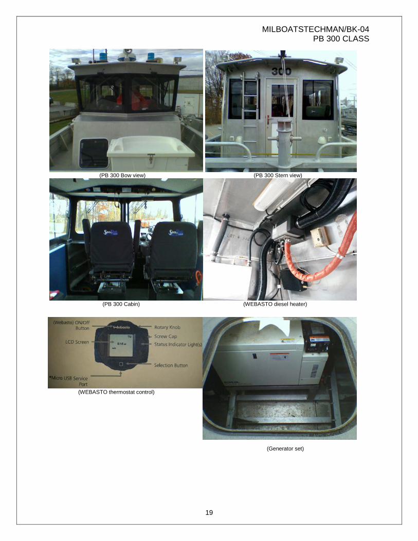
(PB 300 Bow view) (PB 300 Stern view)
(PB 300 Cabin) (WEBASTO diesel heater) (WEBASTO thermostat control) (Generator set)

MILBOATSTECHMAN/BK-04 PB 300 CLASS
20
(Helm console) (Engine controller)
(Electrical switch panel) (Electrical breaker panel)
(Electric control and genset panel) (Battery isolator switches)

MILBOATSTECHMAN/BK-04 PB 300 CLASS
21
MILBOATSTECHMAN/BK-04 PB 300 CLASS

NEW YORK NAVAL MILITIA MILITARY EMERGENCY BOAT SERVICE