Embed Size (px)
Citation preview

-.
I4IL-N-2951O(ECJ12 September 1986
MILITARY SPEC IF1CATION
NAVIGATIONAL SET, AWURN-25, TACAN
This specification is approved for use by the Space and Naval Uarf are Systems Command,Ltepartntentof the liavy, and $s avaflable for use by al1 Departments and Agencies of the Departmentof Defense.
1. SCOPE
1.1 *. This specification covers the requirements and tests for production of a TacticalAir Mavigatlon ~TACJW] all-band transponder, Navigational Set, AN/URN-25, hereinafter referred toas the navigational set, for use in conjunction with a TACAN antenna group to provide navigationalinformation to aircraft.
2. APPL lCABLE DOCWENTS
2.1 Government documents.
2.1.1 Specifications, standards, and handbooks. The following specifications, standards, andhandbook, form a part of this specification to the extent specified he.rein. Unless otherwisespecified, the issues of these documents shall be those listed in the issue of the Department ofDefense Index of Specifications and Standards (DoDISS) and sumlement thereto, cited in thesol citation.
SPECWICATIONS
MILITARY
MIL-E -
MIL-E -
16400
17555
MI1-M-3851O
Electronic, Interior Conununication And NavigationEquipment, Naval Ship And Shore: General Specification ForElectronic And Electrical Equipment. Accessories, AndProvisioned Items (Repair Parts): Packaging OfMicrocircuits, Genera? Specification For
STANDARDS
MILITARY
MIL-sTo-lo9 Qual fty Assurance Terms And DefinitionsMIL-STD-454 Standard General Requirements For Electronic EquipmentMIL-STO-461 Electromagnetic Emission And Susceptibility Requirements
For The Control Of Electromagnetic interferenceMIL-STO-462 Electromagnetic interference Characteristics, t4easurententOfMIL-STD-471 Maintainability Verification/Demonstrati on/EvaluationWL-STD- 740 . Airborne And Structureborne h’oise Measurements And
Acceptance Criteria Of Shipboard EquipmenthilL-sTD-781 Reliability Oesign Qualification And Production Tests:
flxponential DistributionM!L-STO-810 Environmental Test Methods And Engineering Gufdel inesMIL-STO-965 Parts Control ProgramMIL-STD-1310 Shipboard Bonding, Groundtng, And Other Techniques For
Electromagnetic CompatibilityMIL-STD- 1364 Standard General Purpose Electronic Test EquipmentMIL-STD-1387 Procedures For Submission Of Application For Approval Of
Non-Standard General Purpose Electronic Test EquipmentDoE1-sTD-13’99, interface Standard For Shipboard Systems, Electric Power,Section 300 Alternating Current (MetriC]MIL-STD-1472 Human Engineering Design Criteria For Mil it,arySystems,
Equipment And Facilities
L
Beneficial comments [recamndations, additions, deletions) and any pertinent data which maybeofuse in improving this document should be addressed to: Cmander, Space and Uaval Warfare SystemsCommand (SPAWU?-003-121], Uashtngton, OC 20363-5100, by usfng the self-addressed StandardizationDocument Improvement Proposal (DD Form 1426) appearing at the end of this document, or by letter.
ARSC WA FSC 5825
OISTI(IBUTION STATEMENT A. Approved for put)lic release; distribution is unlimited.
Downloaded from http://www.everyspec.com

K:IL-N-2951O(EC)
MS3114
HANDBOOK
MILITARY
Connector, Receptacle, Electric, Series 1, Solder Type,Jam Nut Mounting, Bayonet Coupling
MIL-HDBK-241 Design Guide For Electromagnetic Interference (EMI)Reduction In Power Supplies
2.1.2 Other Government publications. The following other Government publications form a partof this speclf]catlon to the extent specified herein. Unless otherwise specified, the issuesshal1 be those in effect on the date of the solicitation.
PUBLICATIONS
NAVAL MILITARY PERSONNEL COMMAND (NMPC )
NAVPERS 18068 Navy Enlisted Manpower And Personnel ClassificationsAnd Occupational Standards
NAVAL AIR SYSTEMS COMMAND (NAVAI R)
WS-6536E Process Specification Procedures And Requirementswith SCN 1 For Preparation And Soldering Of Electrical Connections
(Copies of specifications, standards, handbooks, aridpublications required by contractors inconnection with specific acquisition functions should be obtained from the contracting activity oras directea by the contracting officer. )
2.2 Other publications. The following document forms a part of this specification to theextent specified herein. Unless otherwise specified, the issues of the documents which are DoDadopted shall be those listed in the issue of the IIoDISS specified in the solicitation. Unlessotherwise specified, the issues of documents not listed in the DoDISS shall be the issue of thenongovernment documents which is current on the date of the solicitation.
ELECTRONIC INDUSTRIES ASSOCIATION (EIA)
EIA RS-3i0-L-77 Racks, Panels And Associated Equipment
[Application for copies should be addressed to Electronic Industries Association,2001 Eye Street, NW, Washington, DC 2(JO06.)
(Nongovernment standards and other publications are normally available from the organizationswhich prepare or which distribute the documents. These documents also may be available in orthrough 1ibraries or other informational services. )
2.3 Order of precedence. In the event of a conflict between the text of this specificationand the references cited herein (except for associated detail specifications, specificationsheets, or MS standards), the text of this specification shall take precedence. Nothing in thisspecification, however, shall supersede applicable laws and regulations unless a specificexemption has been obtained.
3. REQUIREMENTS
3.1 General . The navigational set shall be in accordance with MIL-E-16400, to the ,extentspeci fied~.
3.1.1 First article. When specified in the contract or purchase order, a sample shall besubjected to first article inspection (see 4.3 and 6.3).
3.2 Navigational set description. The navigational set shall consist of a beacon cabinet anda Control-indicator unit (see 6.4.4) suitable for ship or shore installation. The navigationalset shal1 provide 100 properly equipped aircraft with range, bearing, and identificationinformation within a 321.8 kilometer (km) (200 mile (mi)) line-of-sight range. The navigationalset shal1 have a 252 channel capabil ity and require a maximum of 3 minutes to change from anychannel to any other channel without external test equipment or internal adjustments. Vacuumtubes shal1 not be used except for the last two radio frequency (RF) power stages.
2
Downloaded from http://www.everyspec.com

M1L-N-2951O(EC)
3.2.1 MaJor components. The beacon shal1 consist of the major components spec~ fied in a andb, enclosed in one cabinet:
a. Coder-keyerb. Receiver-transmitter
3.2.1.1 Major functions. The functions specified in a through d shall be contained inseparate drawers or contatned within the major components of the beacon cabinet:
a. Monitoring circuitry (see 3.3.3)b. Control -interface circuitryc. Blowers (if requ~red)d. Secondary power supplies
3.2.1.2 Control-indicator. The control-indicator shal1 provide remote control operation andreport beacon status.
3.3 Specific performance requirements. Specific perfonoance requirements Shal1 be asspecif$ed in 3.s.I through 3.3.1.2.3.
3.3.1 Coder-keyer. The coder-keyer shall provide the composite video pulse train to thereceiver-transmitter.
3.3.1. i Coder. The coder shall dev@lop the mafn and auxiliary reference groups, identitysignal, estab~priority between reference groups, Identity, random, and distance reply pulsesand provide pulse pair coding.
3.3.1.1.1 Main reference pulse group. The 15-hertz (Mz) reference group is called the mainreference group. For X-channels, the mafn reference group sha?l consist of a group of 12 pairs ofpulses, and the spacing between pairs shall be 30 *0.3 microseconds [us). For Y-channels, themain reference group shall consist of a group of 13 single pulses spaced 30 *0.3 IISapart.
3.3.1 .1.2 Auxiliary reference pulse group. The 135-Hz reference group is cal led theauxiliary reference group. For X-channels, the auxiliary reference group shall consist of sixpairs of pulses, and the spacing between pairs shal1 be 24 $0.25 VS. For Y-channels. theauxiliary reference group shal1 consist of a group of 13 single pulses spaced 15 *0.2 US apart.
3.3.1.1.3 Precedence. Reference groups shal1 have priority over al1 other portions of theoutput signal. dentlty pulses shall have priority over all but reference groups. i)istance replypulses shall have priority over random pulses only,
For X-channels, tttepulses shall be coded in pairs with a spacingwhic;~ii;~e W For Y-channels, the spacing shall be 30 *0.25 ~s. Delay compensationin the X-channei timing will be accomplished in the antenna group,
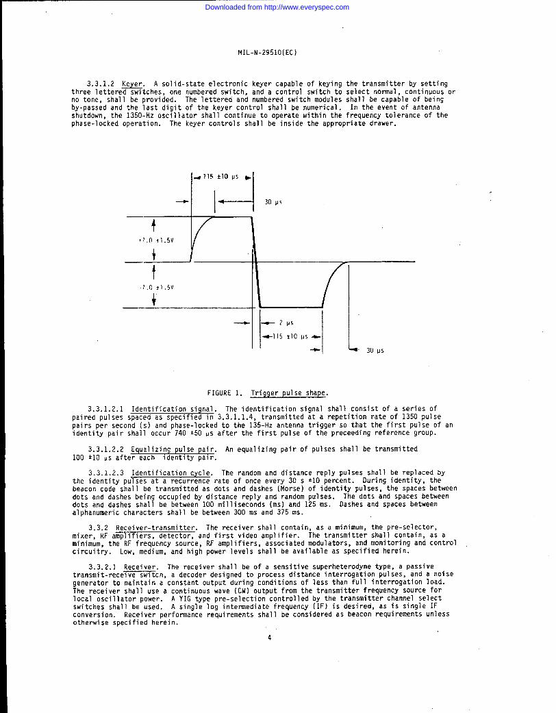
3.3.1.1.5 Antenna tim$nq triggers. The main and auxiliary timing triggers provided to thebeacon from the antenna group shal1 properly operate the burst development circuits. Theircharacteristics are: Amplitude of +7.0 *1.5 volts (V) and -7.0 *1.5 V measured across 10 kilohmsshunted by 0.005 microfarad. These loads shi?l1 be incorporated into the transponder. Thetrigger’s positive excurs~on occurs first and each half alternation has a length of 115 *IO us.The decay time of the positive to negative crossover does not exceed 2 VS. The leading andtrailing edges of the rise and fall of the pulse are approximately 30 PS as shown in FIGURE 1.
A pretrigger output from the beacon shall be provided. The pretriggerat a receptacle located on the cable entrance box.
3.3.1.1.6.1 Pretriq~er characteristics. The pretrigger shall have a lead time of 3.0 VS to10 IIS,measured to the O percent point on the rfse of the transmitter pulse pair, with astability of @.25 us. The pretrigger amplitude sha?l be between +5 V and +50 V, with a pulse-width between 2.0 us and 20 IIS. The output fmpedance shall be 12S ohms. The rise tice shall beless than 100 nanoseconds as measured at the end of 30.48 meter [m) [100 feet (ft)) of RG-58/Ucoaxial cable.
3
Downloaded from http://www.everyspec.com
MIL-N-2951O(EC)
3.3.1.2 -. A solid-state electronic keyer capable of keying the transmitter by settingthree lettered switches, one numbered switch, and a control switch to select normal , continuous orno tone, shall be provided. The 1ettered and numbered switch modules shal1 be capable of beingby-passed and the last digit of the keyer control shall be numerical . In the event of antennashutdown, the 1350-Hz oscil later shal1 continue to operate within the frequency tolerance of thephase-locked operation. The keyer controls shall be inside the appropriate drawer.
4115 flops *
I 1-l* 30 p$
f
+7.0 jl.5v
+ ——
t.7.0 *1.5V
+
— ~2ps
+115 tlo us-
+ ‘1 30 ps
FIGURE 1. Trigger pulse shape.
3.3.1 .2.1 Identification signal. The identification signal shall consist of a series ofpaired pulses spaced as specified in 3.3.1.1.4, transmitted at a repetition rate of 1350 pulsepairs per second (s) and phase-locked to the 135-Hz antenna trigger so that the first Pulse of anidentity pair shall occur 740 *5O us after the first pulse of the preceding reference group.
3.3.1 .2.2 Equalizing pulse pair. An equalizing pair of pulses shall be transmitted100 *1O us after each identity pair.
3.3.1 .2.3 Identification cycle. The random and distance reply pulses shal1 be replaced bythe identity PUTses at a recurrence rate of once every 30 s *1O percent. During identity, thebeacon code shal1 be transmitted as dots and dashes (Morse) of identity pulses, the spaces betweendots and dashes being occupied by distance reply and random PU1ses. The dots and spaces betweendots and dashes shall be between 100 milliseconds (ins)and 125 ms. Dashes and spaces betweenalphanumeric characters shalI be between 300 ms and 375 ms.
3.3.2 Receiver-transmitter. The receiver shall contain, as a minimum, the pre-selector,mixer, RF amplifiers, detector, and first video amplifier. The transmitter shall contain, as aminimum, the RF frequency source, RF amplifiers, associated modulators, and monitoring and controlcircuitry. Low, medium, and high power levels shall be available as specified herein.
3.3.2.1 Receiver. The receiver shall be of a sensitive superheterodyne type, a passivetransmit-receive switch, a decoder designed to process distance interrogation pulses, and a noisegenerator to maintain a constant output during conditions of less than full interrogation load.The receiver shall use a continuous wave (CW) output from the transmitter frequency source forlocal oscillator power. A YIG type pre-selection controlled by the transmitter channel selectswitches shall be used. A single log intermediate frequency (IF) is desired, as is single IFconversion. Receiver performance requirements shall be considered as beacon requirements unlessotherwise specified herein.
4
Downloaded from http://www.everyspec.com

MIL-M-2951O(EC)
3.3.2.1.1 Fre uenc*“
The receiver shall be capable of being tuned126 l-megahertz z c annels centered on integral frequencies between
to any one of the1025 MHz and IMO MHz.
3.3.2.1.2 Triggering level. The recefver shall respond to properly coded interrogations with aresponse percentage of at 1east 60 percent with a tnfnfmum signal strength of -90 decibels referredto one mIfl 1fwatt (d&n) under conditions of 90 percent of ful1 interrogation load. For a no-loadcondition, the minimum signal strength $hall be -92 dBm with an interrogation pulse repetitionfrequency of no more than 150 pulse-pal rs per s. The total number of pulses out of the receivershall not wary from the normal operating settfng by more than 3.3 percent for conditions of normalloading or for a 50 percent overload.
3.3.2.1.3 Demand code. The beacon shal 1 be provided with a switch to select Normal or OemandTACAN mode. In the I)eman&mode, the transmt tter $hal1 remain in a standby condi tlon unti1 anaircraft interrogates the beacon with a proper interrogation.
3.3.2 .1.3.1 Triggering level. Under the no-load condition, when an interrogation is requiredto activate the transmitter, th -IS activation shal1 occur when the minimum fnput signal strength isat most 3 decibels (dB) greater than the no-load sensitivity as specified in 3.3.2.1.2. Adiscerrtable interrogation period of 3 s to 4 s shall elapse before the transmitter turns on.
Mhem the interrogation rate drops to less than an average of 12 per s,an a~~~&~;~”;el&%#%~ld the transmitter in the on-air condition for a period of 1 minute to3 minutes before returning to the standby condition.
3.3.2.1.4 Bandwidth. The bandwidth of the receiver shal1 be such that the triggering levelshal? not deter~orate by more than 3 dt)when its total frequency drift is added directly to anincoaing frequency drift of $100 kilohertz (kHz).
The receiver shall reject properly coded interrogations centered onfre&~~~~~-&%%%%$~d from the nominal input frequency which have an amplitude of 80 dB abovethe receiver threshold. Interrogations arriving at all IFs shal1 be suppressed by 80 dB. Otherspurious responses within 960 MHz to 1215 Wlz and image frequencies shal1 be suppressed at least65 dD.
The receiver decoder timing shall be.derived from the first pulse of aninte~~~~~~~~~ p%%%er conditions of interrogations by pulse pairs having a deviation from thenominal 12 *S or 36 us by *0.5 us, the receiver triggering level shall not decrease by more than1 dB. Under conditions when the pulse pa$r spacing deviates from nominal by more than *2 Ps, thereceiver sensitivity shal1 be reduced by at least 70 dB. The receiver shal 1 not respond to singlepulse interrogations.
3.3.2.1.7 Res onse delqf+%-’-+’
The response delay, measured from the half amplitude point on theleading edge o t e Irst nterrogation pulse to the half afnplitude point on the leading edge of the
‘ first reply pulse shal 1 be 50 MS for X-channels and 56 9S for Y-channels. Tolerances shal1 be:
Input signal Oelay variation
CldBm to -10 dih *0.5 0s-10 dihnto -70 dllm *0.25 us-?(IdBm to -90 dBm *o+~ us
3.3.2.1.8 Dead time. The transponder dead time shall be measured from the trailing edge of adecoded pulse pair (from an interrogation or noise). The blanking shall be set at 60 *1 vs forX-channels and 66 *I ps for Y-channels. The transponder shall be adjustable from these values by*2O Ps.
3.3.2.1.9 Echo suppression. The receiver shall contain an interrogation level sensing circuitto detect any interrogating purse pair that is adjustable from 10 dB to 40 dB above threshold. Theoutput of this level sensor shall be used to initiate rece~ver desensitization to any incomingsignal level which is less than the preset threshold. The desensitizing gate shall be continuouslyadjustable between the limits of 150 HS to 400 IJS, Any interrogation signal greater than the presetthreshold shall be allowed to passand shall initiate the desensitization period again regardless ofwhether it occurs during a previous desensitization period or not.
5
Downloaded from http://www.everyspec.com

MIL-N-2951O(EC)
3.3.2.1.10 Pulse count output. The total receiver pulse output, from either interrogations ornoise shall be controllable such that the total count can be varied from 2700 pulses per s to401Xlpulses per s.
3.3.2.1.11 CM interference. In the presence of on-channel and off-channel CW interference,the receiver sha_l1 respond to valid interrogations that exceed the CW interference by 10 dB ormore. Conformance to this requirement shal1 be achieved with CM input signal strengths fromthreshold level to -30 dBm. The response delay tolerances, as a function of signal to CWinterference, shal1 not exceed:
Level of signal level above CW level Delay tolerances
10 dB to 20 dB *1.2 us
20 dB to 90 dB :Input signals equal to orless than -10 dBm *0.375 us
Input signals greaterthan -10 dBm *0.75 lls
3.3.2.1.12 Narrow pulse interference. The receiver shal1 not reduce the traffic handlingcapabil ity of the beacon in the presence of single input pulses or of pairs having the spacingwithin the tolerances of the decoder which have a duration of 1.2 us or less.
3.3.2.1.13 Additional decoder capability. As a growth feature, adequate space shal1.beavailable in the coder-keyer card deck to add at least three additional circuit boards for futureuse.
3.3.2.1.14 Squitter distribution. Squitter distribution shall be as shown in FIGURE 2.
3.3.2.2. Transmitter. The transmitter shall be as specified in 3.3.2.2.1 through 3.3.2.2.7.6.
3.3.2.2.1 Frequency source. The frequency source shal1 be synthesizer control led by channelnumbered switches and shall provide 252 channels from 962 MHz through 1213 MHz. An illegaladdress (incorrect channel number), shal1 result in no output, and shall activate the illegalchannel alarm. A direct phase-locked type is recommended. Spurious signal off of centerfrequencies shal1 be down greater than 95 dB at frequencies *63 MHz from the operating frequenciesand at 1east 70 dB down at the other frequencies in the band. The frequency source shal1 bedirectly interchangeable both physically and electrically with the monitor synthesizer.
3.3.2 .2.1.1 Frequency lock time. The synthesizer shall be capable of locking on to anyfrequency, having been on any other frequency, in a maximum of 500 ms.
3.3.2 .2.1.2 Frequency outputs. Two RF outputs shall be provided, one output to the firsttransmitter amplifier and the second output to the beacon receiver mixer.
3.3.2 .2.1.3 Antenna control logic. The channel select circuitry shall provide, at thetransponder cable entrance box, three separate two-line logic signals, derived from the channelsetting, where logic U is -0.5 volts direct current (VDC) to +0.5 VDC, 20 milliamperes (mA)sinking current maximum. Logic 1 is +2.5 VOC to +5.0 VDC. Logic 1 will be a minimum of +3 VDCwith 1 MA source current. The switching logic shall be as specified in TABLE I.
TABLE 1. Switching logic.~— r
Frequency (MHZ) Y mode Band code
962 to 993 0994 to 1024 0
&u_ti
I
6
Downloaded from http://www.everyspec.com

.
RANDOM
PULSE
DISTRIBUTION
LIMIT3
Atots!of1000
radln~
ofthespzeingof&a
mnd
omPUIUM(2700pulses
porseurnd)shallhe
tzzkan.RrtrdingzihatllM
~mulati
In25
Bcoc
intar.
vah
rndthenumLrero
frmxlinprin
each
intervalshaiitm
plottodon
thit
figwrt.Of
the49
pohm
plottd;3may
Iiaabove
&muppercoliiiina,
3may
iiaboiow
theiowr
eolidline,butnomore
tfwz
5may
lieouts-tie
tfw~ion
boimdd
bythezolidIinm,andno
mom
than
1may
liewt$ida
theregionboundodby
dwdotwl
iinas.In
rddition,no
more
than
1(KIof
the10@3
reodinpimay
axoe
edIOIW
gzsc
andno
MO
Mth
en10
retii~
may
foiitr+hw
00I,w+3c,
&r so v-l
s m n
FIGuRE
2.Pulse
spat
irrg
inmicroseconds.
Downloaded from http://www.everyspec.com

M1L-N-2551O(EC)
3.3.2 .2.1.4 YIb pre-selection control logic. The channel select circuitry shal1 provide therequired logic to control the YIG pre-selector through the 1025 MHz to 115G MHz tuning range.
3.3.2.2.2 Solid-state RF amplifier (driver). The solid-state amplifier shal1 amplify theinput RF signal from the synthesizer, and, with its associated low level modulator, shall providea suitable output to either the following RF cavity amplifier or as a Gaussian source for thefirst or low level beacon output (see 3.3.2.2.6). The solid-state amplifier shall be contained ina single module (exclusive of modulator) and shall be designed to operate without forced aircool ing throughout the frequency, power, and temperature ranges. The solid-state amplifier shallnot require user-operator requi rea frequency tuning adjustments. The last RF output stage shallcontain no more than two active devices. The amplifier shall be capable of operating into an openor shorted 1ine without damage.
3.3.2 .2.3 Low level amplifier modulator. The low level modulator shall provide the keyingsequence and necessary pulse shaping to the solid-state amplifier. Adjustments shall not benecessary to maintain spectrum when changing from one channel to another. Preventive orcorrective maintenance adjustments shal1 be kept to a minimum and be made with the aid of ageneral purpose multimeter and oscilloscope only.
3.3.2 .2.4 Intermediate and final power amplifiers. The intermediate and final output shal 1be tube stages which are physically separate, identical, and interchangeable assemblies. Thesetube stages may share a common modulator and voltage source. The tubes shall be of theceramic-metal planar triode type. Tube replacement shall not require tuning adjustments, otherthan front panel tuning, and no solder connections. Tubes procurable under the contractor’ssource control drawing shal1 conform to the minimum requirements of this specification. Totaltime to replace a tube shal1 be not more than 10 minutes, with no special tools required. Tuningcontrols shall be limited to not more than two per stage. The tuning controls shall havecalibration. If calibration is not directly readable in channel number, a calibration chart shallbe permanently affixed to the transmitter front panel . Filtered forced air cooling may beutil ized for the power amplifier stages but air shall not pass internal ly through the cavities.The amplifiers shal1 be capable of operating into an open or shorted line without damage.
3.3.2 .2.5 High level modulator. The high level modulator shall provide the keying sequenceand drive to the tube stages to maintain proper output. Operator tuning adjustments shal1 not berequired to maintain transmitter output performance criteria. Preventive or correctivemaintenance adjustments shall be kept to a minimum and shall be made with the aid of a generalpurpose multimeter and oscilloscope only. A panel switch shall be provided to set the modulatorfor medium or high power output and the switch may be used to provide for single or dual stageoperation. A second switch 1ocated internal ly may be required for the emergency operation mode ofsingle stage operation.
3.3.2 .2.6 Output power levels. The beacon shall be capable of operating (maintainingtransmitter output characteristics of 3.3.2.2.7) at three power levels across the 962-MHz through1Z13-MHZ band as measured at the transmitter output connector. A front panel control may beprovideo to permit setting the power level to the tolerances specified:
Power Source Power output
LOW Sol id-state amplifier 150 Watts (W) peak minimumMia Intermediate power amplifier (IPA) 7LIGW peak *1O percentHigh Power amplifier (PA) 300G W peak *1O percent
The IPAS amd PAS shall conform to their rated power outputs after 1000 hours of beacon oPeratin9time.
3.3.2 .2.6.1 Emergency operation. The 150-W and 700-W operation shall be achievable bydisconnecting ana reconnecting RF cables to bypass mid and high power stages. Additional cabl ingrequired for reconnecting shall be affixed to the inside of the transmitter drawer.
3.3.2 .2.6.2 RF feed cable. The RF output cabling internal to the cabinet shal1 remainconnected when the drawer is opened for servicing. Times Wire SF 14ZB cable and a retractor andS1ide assembly of the Jonathan 150 QOP button type, or equal , is recommended.
8
Downloaded from http://www.everyspec.com

3.3.2 .2.6.3filter to reject
I41L-N-2951O[EC)
croon transmit and receive line shall contain a low passsignals above 1600 MHz.
3.3.2.2.7 Transmitter output characteristics. Conformance to the transni tter outputcharacteristics spec~f~ed In 3.3.2 .2.6 shall be achfeved throughout the 962-t4Hz to 1213-MHz bandat all three power levels.
3.3.2 .2,7.1 Ptflse shape. The pulse envelope, as detected by a linear detector, shall have arounded shape falling within the limits of 3.3.2 .2.7.1.1 through 3.3.2.2.7.1.4.
3.3.2 .2,7.1.1 Pulse rise time. The pulse rise t$me ts the ttme required for the Teading edgeof the pulse to rise from 10 percent to 90 percent of the maximum voltage amplitude, The pulserise time shall nominally be 2.5 us, but shall not exceed 3.0 VS. The minimum rise time isgoverned by the spectrum requirements of 3.3.2.2,7.2.
3.3.2 .2.7.1.2 Pulse decay time. The pulse decay tfme is the tfme required for the trailingedge of the pulse to decay from 90 pewent to 10 percent of the maximum voltage amplitude. Thepulse decay time shall be nominally 2.S Ps, but shall not exceed 3.0 MS. The minimum decay timeis governed by the spectrum requirements of 3.3.2.2.7.2.
3.3.2 .2.7.1.3 Pulse toT-l+-
The instantaneous amplitude of thepulse shall not, at any instantbetween the point o t e eadlrig edge which ts 95 percent of the maxfmum voltage amplitude and thepoint of the trailing edge which is 95 percent of the maximum amplftude, fall belowa line whichis 95 percent of the maximumvoltage amplitude af the pulse and is parallel to the baseline.
3.3.2 .2.7.1.4 Pulse duration. The pulse duration measured between points on the leading edgeand trailing edge 01 the pulse which are 50 percent of the maximum voltage amplitude of the pulseshall be 3.5 ~0,5 OS.
3.3.2 .2.7.2 RF pulse spectrum. The energy level contained in each of two 0.5 MHz-bandscentered on frequencies *0. FJMHzabove and below the channel frequency shall not exceed200 milliwatts (mW), and the energy level contafned in each of two 0.5-Miz bands centered onfrequencies *2.O I$liizabove and below the channel frequency shall not exceed 2.OIEli.
3.3.2 .2.7.3 Pulse droo+
Prfor to antenna amplitude modulation of the composite RF pulsetrain, the percentage m u atlon of the pulse train at 15 Hz and 135 Hz shall not exceed 1.0percent for each. This modulation shall be measured with the transmitter operating norrally andshall include the effects of droop and recovery time of the main and auxiliary reference groups.Spurious modulation at 120 Hz shall not exceed *1.O percent.
3.3.2 .2.7.4 Ctioutput, Clf output between pulse pafrs shall not exceed 5microwatts with thebeacon in normal operational mode, The peak signal amplitude for 1 MS between pulses of a pair onX-channels and 19 us between pulses of a pair and pulses of the main reference group on Y-channelshall be at least 20 dB below the peak pulse amplftude. During the Y-channel auxiliary referencegroup, the energy shall be at least 20 dilbelow the peak pulse amplitude for at.least 4 US betweenpulses of the group.
3.3.2 .2.7.5 Frequency stability. The transmitted .frequency shall be maintained within*0.002 percent 0{ that specitied in 3.3.2.2.1.
3.3.2 .2.7.6 Duty cycle. The duty cycle shall conform to the requin?ments of continuousoperation with the pulse repetition rate of 7200 pulses per s to 9800 pulses per s.
3.3.3 Beacon monitoring. Monitoring circuitry shal?, whenever practical, be installedphysically and electrically in close proximity to the beacon circuit being monitored. Monitoringcircuitry shall not share the same cards as functional circtd try.
3.3.3.1 lton~tor$ng alarms. Uhenever a xtonitor$ng c$rcuit detects an out of tolerancecondition, an alarm signal shall be developed. This stgnal shall be programmable by switches orjumpers on the appropriate logic circuit card to deliver a hard or soft failure signal to thebeacon control circuits. An internally adjusted delay from 5 s to 10 s shall activate thetransponder control circuits. An internal switch shall be provided to inhibft this alarm.Placing the nornsal/test switch (see 3.3.5.3) fn the testposition shall also inhibit the alarm.An indicator displaytfig the monitor inhibtt condition shall be provided on the transponder and onthe control-indicator. Reply delay shall be wired as a hard failure. The alternating current(AC) ?ine shall be wired as a hard failure, subject to the reset feature (see 3.3.6.1).
9
Downloaded from http://www.everyspec.com

MIL-N-2951 O(EC)
3.3.3.2 Monitored parameters and tolerances. The parameters and tolerances shal1 becontinuously and independently monitored as specifies in TABLE 11.
3.3.3.3 Monitor alarm indicators. All monitor alarm parameters shall be individually displayedon indicators that are vertically aligned on one side of cabinet panels ana shall be prominentlyidentified. Instantaneous failures shall be indicated by a 1-s memory and failures exceeding alarmlimits shall be held in memory until manually reset. Alarm failure time limits shall be held inmemory unti1 manual ly reset.
3.3.3.4 Monitor fail-safe. A monitor fail-safe function shall be provided that exercises each“of the monitored parameters to verify its error detection capabi 1ity.
3.3.4 Beacon metering. Significant voltages, currents, and RF power levels shall be metered.The KF power metering shal1 be of a peak type and shall measure the 10W, medium, anc high power1evels at the system output with an accuracy of ●1O percent and through the range of 1000 pulse pairsper s to 5000 pulse pairs per s. General purpose test equipment (GPTE) may be used. Power supplyvoltage readings shal1 be centered on the meter scale within a green 1ine tolerance area.Calibration adjustment shall be provided.
3.3.4.1 Metered transmitter levels. As a minimum, the levels specified in a through h shall bemetered:
::c.d.e.f.9-h.
RF driver output power to an accuracy of *1 dBRF IPA output power to an accuracy of *1 dBRF PA output powerReflected output power to an accuracy of *1 dBIPA and PA cathode currentIPA and PA cathode bias voltageIPA and PA plate voltageAl. input line voltage
TABLE 11. Monitored parameters and tolerances.
Nominal value orParameter range, or both No alarm Alarm
ID ~/ statusPeriod 30 s +10 percent +lUO percentContinuous O.10IJ s and 0.375 s 0.5 s 5.0 sPulse spacing 12 VS and 311us *u.6 PS *1.O psRX sensitivity 2/S/ -90 dBm to -52 dBm 60 percent replies 50 percent
repliesuuty cycle S/ 7200 pulses to 9800 pulses 3.3 percent 10.0 percentReply delay~/ 50 PS and 56 ~s *U.6 us *1.(JusAC line 60 Hz or 400 Hz, 115V *5 percent frequency
10 percent voltage ;;Data link 45 s <3(Is percent ;60 SSynthesizer statusCavity temperature i! 6/Spectrum control ~/ ‘(if feedback circuit used to control spectrum)BurstMain X 12 pulse pairs
Y 13 pulses :: %Aux X 6 pulse pairs 7/ T
Y 13 pulses gl TG/—
Adjustment controls may be provided to set any of the tolerance limits; however, only a generalpurpose oscilloscope, counter, and multi meter shall be necessary.
1/ Identification2/ Measured at -84 dbm~/ The RX sensitivity and duty cycle alarm lights shall not flash when the IO tone is
transmitted.Measured at -40 dBm
3 Nominal values and tolerances to be determined by manufacturer; however, limits shall bewithin levels below those resulting in beacon out of tolerance conditions and resulting indamage to the equipment.
10
Downloaded from http://www.everyspec.com
~/ Cavity temperaturerequired.
7/ Lose 1 pulse pair~1 Lose 1 pulse~/ Lose any 2 or more~0/ Lose any 2 or more—
3.3.4.2 Lam test.*of MIL-STD-14
MIL-N-29510(EC)
shall be monitored by a temperature sensor. Monitoring of air flow is not
pulse pairsPU1ses
A lamp test switch shall be provided for lamp testing. The requirements
3.3.4.3 Time totaliz.ingmeter. A time total izing meter t$ required. This meter shall be inthe tube filament line and shall display five significant di~its fn hours.
3.3.5 RF test generator. The monftor ctrcuitry shall be capable of functioning as an RF testgenerator across the receiver band.
3.3.5.1 Synthesizer. The monitor synt.hes~zer shall have the features specified in a throughc:
Be directly interchangeable with the receiver-transmitter synthesizer~: Have an externally programb}e frequency control !n i4Hz steps which is
independent of the transmitter frequency controlHave a frequency devfation control to extend the interrogation band *3 Mtlz in
100-kHz steps!”
3.3.5.2 Monitor modulator. The monitor RF modulator shall be prugrarrmable to provide avariable pulse modulation from 60 pulse pairs per s to 4000 pulse pafrs per s. A dial markident.ifyinq the 2700-pulse pair rate on this range shell be provided. Fixed pulse pair spacingsof 10 US, 12 US, 14 vs, 34 US, 36 US, and 38 KS, wfth a tolerance of *0.5 us, as well as avariable spacing control of from 10 PS to 40 PS, shall be provided.
3.3.5.3 Variable attenuator. A variable attenuator calibrated fn l-dB steps through therange from O dB 100 dB with an accuracy of $0,5 dB, shall be provided. The uariableattenuator shall%e bypas;ed when not in the test pos~tion by a normal/test switch which shallalso disable the programmable modulator pulse rate and spacing controls.
3.3.5.4 Test output. A panel-mounted test output jack shall provide a sample of the detectedRF output when the normal/test switch is fn either position.
3.3.6 Control circuits. The control circuitry shall provtde the functions of transpondercontroi, local and remote beaconsystem control, control-indicator, antenna group interface, andvoice cmunication to the control-indicator (see 3.3.7b).
3.3.6.1 Transponder control. The transponder control circuftryshall provfde for manual turnon, off, standby, and test operation, start up and shut down sequencing, automatic power failure,transient and overloac protection, and monitor control. A test position shall connect thetransmitter output to an internal dumm$y load. ~ndicators shall display beacon status of standbyand on-air. I/henAC power at the equipment reaches the alarm tolerances of 3.3.3.2, the equipmentshall automatically shut down before damage occurs. Hhenever AC power is within tolerance, theequipment shall return to its previous ON state after approximately 10 s to 20 s (plus requiredtube warm-up) and the AC line monitor lamp shall illuminate as a soft.failure indication, Thehigh voltage arc detection circuits, when tripped, shall automatically reset three times and thenremain open until manually reset. If operation is not Interrupted for 20 s, the circuits shallautomatically reset to the normal positton. For power faflures of short duration when the time ofpower loss is less than necessary to reinitiate power supply time delays, thesedelaysshallbebypassed to achieve optimum on-air time without damage to equipment. The channel select switchesshall be enabled on?y in the TUNE mode. Changing channels fn the ON-AIR, TEST, or STANDBY modesshall enable the illegal channel alarm and automatically switch the beacon to the STANDBY mode.
3.3.6.2 Single and dual beacon system control. The system control circuitry shall be suchthat a dual beacon Installation shall consist of two identical beacons requfring an additionalcontrol cable between the two to control priority of primary and secondary beacon operation.Operation shall be such that one beacon can be selected as the installation primary. Cableconnections to the antenna, antenna control, status control indicator, and ancillary equipmentsshall be madefrom the selected beacon. The corresponding jacks on the secondary beacon shall be
11
Downloaded from http://www.everyspec.com
MIL-N-2951O(EC)
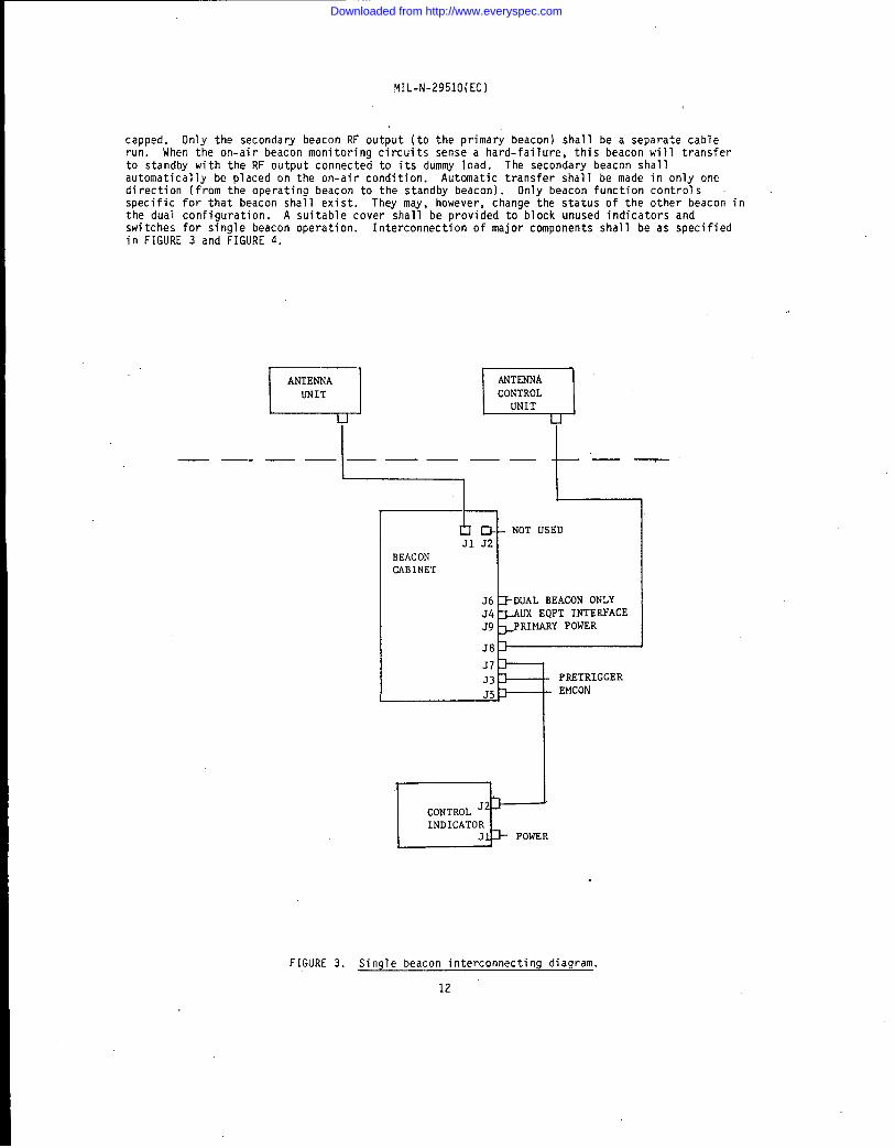
capped. Only the secondary beacon RF output (to the primary beacon) shal1 be a separate cablerun. When the on-air beacon monitoring circuits sense a hard-failure, this beacon will transferto standby with the RF output connected to its dummy 1oad. The secondary beacon shal1automatically be placed on the on-air condition. Autanatic transfer shall be made in only onedirection (from the operating beacon to the standby beacon). Only beacon function controlsspecific for that beacon shall exist. They may, however, change the status of the other beacon inthe dual configuration. A suitable cover shall be provided to block unused indicators andswitches for single beacon operati on. Interconnection of major components shal1 be as specifiedin FIGURE 3 and FIGURE 4.
mm—— —— l————— t——
I
rl NOTUSEDJ1 J2
BEACONCABINET
J6
E
DUALBEACONONLYS4 UX EQPTINTERFACEJ9 PRIMARYPOWER
J7J3.15h=
I wCONTROL‘2
I INDICATORJ]b POWER
PRRTRIGGEREMCON
FIGURE3. Single beacon interconnecting diagram.
12
Downloaded from http://www.everyspec.com

NIL-N-2951 o(Ec)
—— —.
[J
BEACONCABINET(PRIMARY)
—. —— . .
t
——
t
J2
.J61-J4k AUX&QPTIN .’4J9 4PRWI,ARYPO El
J
CONTRIIL
EINDICATORJl,
T.J1 32
BEA#NCABINET(SECONDARY)
36$4
S938.J7J3
—
+
.NOTUSED
)- AUXEQPTINTFC~PRIMMW POWER~NOT USED~NOT USEI)
~ PRETRICGER* EMCON
FIGURE 4. Oual beacon interdonnectfng diagram.
13
Downloaded from http://www.everyspec.com

MIL-N-2951 O(EC)
3.3.6.2.1 Beacon and antenna group interface. The system of controls and interlocks,specified in a through f, shall be provided to interface the beacon with the antenna group in anoperational installation:
The main and auxi1iary reference triggers shal1 be provided to the beacon eachby a separate s~~elded twisted pair (see 3.3.1.1.5).
b. A soft fail alarm signal shall be provided to the beacon by a contact open on ashielded twisted pair. Maximum load to be handled on this line is 28 VDC, 100 MA.
c. A hard fail alarm signal shall be provided to the beacon by a contact open on ashielded twisted pair. The maximum load to be handled on this line is 28 VDC, 100 MA.
d. A remote turn-on signal to the antenna group shal1 be provided by a +26 VOClevel signal on a shielded twisted pair. Maximum load to be handled on this line is 200 MA at+28 VDC.
e. The beacon ready shal1 be provided to the antenna group on two separateshielded twisted pairs where logic O is -0.5 VDC to +0.5 VDC, 20 MA sinking current maximum.Logic 1 iS +2.5 VOC to +5.0 VDC. Logic 1 shall be a minimum of +3 VDC with 1 MA source. A 01signal shall represent the 3 kilowatt (kW) power, a 10 signal shall represent the 700-W power, a11 signal shal1 represent the 150-W power, and a 00 signal shal1 represent beacon not ready.
f. Antenna band switching signals shal1 be provided to the antenna group on threeseparate shielded twisted pairs where logic O is -0.5 VDC to +0.5 VDC, 20 MA sinking currentmaximum. Logic 1 is +2.5 VOC to 5.0 VDC. Logic 1 shall be a minimum of +3 VOC with 1 MA sourcecurrent. The switching logic shal1 be as specified in TABLE III.
TABLE II1. Switching logic.—
Frequency (MHz) Y mode
‘~
8and code
962 to 993 0 00994 to 1024 0 01
1025 to 1055 1 001056 to 1087 1 011088 to 1119 1 101120 to 1150
L1 11
1151 to 1181 0 101182 to 1213 0 11
This signal shall be initiated by the synthesizer frequency setting switches. Maximum load to behandled on this line shall be +5 VW, 100 MA.
3.3.6 .2.1.1 Interface cable. The interface cable carrying the signals specified in 3.3.6.2.1shall be a type 2SWU-12 with a maximum length of 15.24 m (50 ft). The mating connector to besupplied shall be a Bendix Part Number 10-214628 -21S, or equivalent.
3.3.6.3 Emission control. The navigational set TACAN shall provide radiation status to aremote location, AN/SSQ-82(V) &lute system, through a separate connector on each transponder. Thisconnector shall be in accordance with MS3114, Part Number MS3114E-12-1OS with pin functions asfollows:
Pin Function—
A Oeny command signal (+12 V) that silences thetransponder until +12 V is removed
B DC return for Oeny connnand
c Short circuit between C and D provides aclosed circuit
o When mating plug is connected
E External voltage source (+12 V) for Pin FOeny cormnand acknowledgment
F +12 V from Pin E via closed relay contactacknowledging the receipt of a Deny command
14
Downloaded from http://www.everyspec.com

MIL-N-2951O(EC)
Pin Function—
G Radiate indication signal from transponder tobe +12 V from Pin H vfa relay contact closingwhenever transponder is radiating
ii Cxternal source of +12 V for radiate indicationsignal
J Ground from external equipment to be conducted totransponder ground
3.3.6.3.1 Functional operation. Functional operatfon shall be as specified fn 3.3.6 .3.1.1through 3.3.6.3.1.3.
3.3.6 .3.1.1 flonftor function. The monftor functfon requfres that the transponder provide anindication of wtte~iter or not It fs on the air; that fs, any condition of output power: tune,test, low, mid, or high power. Closed relay cont,acts shall be provfded between Tennfnal G andTerminal H. Contacts sha?l be rated for 50 W, 100 mA maximum.
3.3.6 .3.i.2 Control function. The transponder shall be capable of having its output powercapability being ~ostantaneously silenced (Oeny and Permi t). The Deny co!mnand shal1 be actuatedby the applicat~on of +12 V to P$n A w$th Pin B as the 12-V return. Removal of the +12 V to Pin Ashal1 eye? e the transponder from Deny to Pennlt returning the transponder to fts normal operatingstatus, ~ith operator interaction permitted.
3.3.6 .3.1.3 Acknowledge function. The transponder shall acknowledge the receipt of a Oenycoasand by closing relay contacts between Pin E and Pin F and opening these contacts upon cyclingback to Permit. Contact rating shall be 50 VDC, 100 mA maximum. Normal ly the external equipmentwill supply +12 V to Pin E.
3.3.7 Control-indicator. The control -indicator shal1 prov~de the indicators and controls tointerface w~th the beacon as specified in a through g:
Provide control for one or two beacons to put either in standby or onrair andprovfde fnd;~ator 1ights for dark adapted areas to df$play status. An ind$cator to provide statusof ?oca} and remote control shall be provided. Light sources shall be electrically dimmercontrol 1M by a single adjustment. A lamp test switch shall be pswided to test a~l lamps. Asuitable cover shall be provided to block unused indicators and switches durin~ single beaconoperation. The standby beacon shal1 automatically be connected to a beacon internal dummy load.It shall be possible, in normal operation, to switch a beacon from on to standby and back to on inless than 5 s.
b. Provide two-way voice cmunfcatfon between the local and remote sites with anaudio alarm operating in response to a ringing signal originat~ng at either site. A telephonehandset shal1 not be used. A panel mounted loud speaker and a nondetachablee microphone shal1 beused.A Shure Model 4138Bon a retractable (coiled) cord with a push-to-talk (PTT) button, orequivalent microphone, is recommended. Activating only the PTT button shal1 allow a voice signalto substitute or multiplex with the status and control sfgnals. A 45 s memory shal1 hold thestatus displayed on the indicators during voice if the voice is not multiplexed with the statuss$gnals. A loud speaker volume control shall be provided at both sites. Speaker power shal 1 be aminimum of 2 W.
c. Provide monftor alarm signals, both aural and visual. A soft failure shall beindicated by a flashing amber light and a hard faflure shall be indicated by a steady ned lightand, in addtion, an aural alarm shal1 sound. An internal adjustment shall be provided that wiltallow a range adjustment to the aural alarm of at least 9 dB. An aural defeat switch sha11 beprovi dea.
d. Provide control to put the on-air beacon in a medium or highhiqh power being the 3-kW level and medium Dower beinq the 700-14level.-.
e. %ovtde control and an indicator to pr~vide operation of theOF both.
f. Provide an fndicator to display the monitor inhibit functionthe transponder only.
!t- The control-indicator shal1 have the features specified $n 1mfnimum:
power output mode;
Womal or Demand mode,
which is controlled at
through 3, as a
15
Downloaded from http://www.everyspec.com

1. Alarms:
2. Status:
3. Controls:
MIL-N-2951O(EC)
Hard fail indicatorSoft fail indicatorTransmission line fail indicatorAural alarm
Monitor inhibitRemote controlEmergency Mode (indicates 150 !4or 700 W with singlecavity)Service (for Demand Mode)On-airStandby
Normal or demandHigh or medium powerOn-air or standbyAural alarm defeatLamp testLamp dimmerAudio volumeRing initiate
3.3.7.1 Interface cable. The interface cable shall be a two-wire telephone line. Functionsof the control -lndlcator shall be controlled over this line. For long runs this shall be adedicated 600-ohm line with some lightning protection. Additional lightning protection within theequipment is desired. For distances up to 76.20 m (250 ft), a 120-ohm line may be used. Anon-air status signal shall be available at J2 on the control-indicator. A closed contact shallindicate a beacon on-air condition. Relay contact rating shall be 1.0 ampere at 60 V.
3.3.7.2 Lfne signal characteristics. Line levels shall be adjustable to allow compatibilitywith world-wide conunerclal telephone line standards. Sufficient energy shall be available toallow transmission through wet-field wire with useful signals available at distances of at least4.827 km (3 mi). The remoting system shall be fail-safe to the extent that any abnormality in thetelephone line which would prevent its conveying the beacon status information to the remotelocation shall cause an alarm at the remote site. The operation of the beacon shall not beaffected by the opening or shorting of the line. Loss of telephone line data, along with a powerinterrupt to the beacon shall cause the beacon to reinitialize in the STANDBY mode until telephoneline data are resumed.
3.3.8 Ancillary equipment interface. The signals shall be available at an MS jack on thebeacon cabinet cable entrance box as specified in a through f:
a. An identification keying signal of logic O is -0.5 VDC to +0.5 VDC, 20 MA sinkingcurrent maximum for the key up position and logic 1 is +2.5 VOC to +5.0 VOC, 20 MA source currentmaximum for the key down position.
b. A hard failure signal of logic O is -0.5’VOC to +0.5 VL)C,20 MA sinking currentmaximum for the failure alarm and logic 1 is +2.5 VOC to +5.0 VUC, 20 MA source current maximumfor the no alarm condition.
c. A soft failure signal of logic O is -0.5 VOC to +0.5 VOC, 20 MA sinking currentmaximum for the failure alarm and logic 1 is +2.5 VOC to +5.0 VIIC,20 MA source current maximumfor the no alarm condition.
d. A beacon ready signal of logic O is -0.5 VOC to +0.5 VDC, 20 MA sinking currentmaximum for ready condition and logic 1 is +2.5 VDC to +5.0 VDC, 20 MA source current maximum forthe opposite condition.
An on-air signal of logic O is -0.5 VDC to +0.5 VOC, 20 MA sinking current maximumfor a no ha% or soft failure condition and logic 1 is +2.5 VOC to 5.0 VDC, 20 MA source currentmaximum for the failure condition.
f. Chassis ground
3.4 Parts, materials, and processes. Parts, materials, and processes shall be in accordancewith the ‘parts, mater~als and processes paragraph of MIL-E-16400, except that prior to selectionand request for approval of nonstandard parts and materials, the procedures in MIL-STO-965,Procedure I shall be followed.
16
Downloaded from http://www.everyspec.com

MIL-N-2951O(EC)
3.4,1 Parts. Parts shall be as specfffed fn 3.4.1.1 through 3.4.1.5.
3.4.1.1 Microelectronic devices. 14icroelectronic devfces employed in the design of thenavigaticmal set requirlng 141L-M-385 10, Class 8 devices, shall conform to MIL-STO-454, Requirement 64.
3.4.1.2 Control lockinq devices. Control locking devices are required and shal1 be designed inaccordance with the Shaft locking devices paragraph of #lIL-E-16400, except that switches or othercontrols hawing detent mechanisms need not have locking devices.
3.4.1.3 Fuse locations. Fuses and spares for each shall be located on front panels.
3.4.1.4 Indicator switches. Flush-maunted $ndicator switches, if used, shall be serviceablefram the front of the mounting panel.
3,4.1.5 Dial sizes and illumination. Dial sizes shall be proposed by the contractor and subjectto the approval of panel layouts . 111Unsination of dfals, switches, and controls shall be requiredonly where necessary to permit the channel changing operatfon in darkened areas and shal1 be requiredfor all functions of the control-indicator (see 3.3.7).
3.4.2 Processes. Processes shall be as specified in 3.4.2.1 and 3.4,2.2.
The exterior of the equipmant shal1 be in accordance wfth the Painting ‘para~;;~”;f %%%00.
3.4.2.2 Soldering. Solaering shal1 be fn accordance with WS-6536E with SCN 1.
3.5 Environmental conditions. The beacon shall operate properly within the service conditionsfor a sheltered control lea environment of MIL-E-16400, except as specified in a through h:
a. Ambient temperature (aperatfng). -28: Celsius (C) to +65~Cb. Ambient temperature (nonoperating or storage). Range 4 of 14iL-E-16400c. Altitude. O m to 3048 m (10,000 ft) above mean sea level [MSLId. Altitude (nonoperating or storage). O m to 15,000 m (50,000 ft) above MSLe. Salt fog ispr~). The requirements of the Salt fog (spray) paragraph of MIL-E-16400 for
sheltered equipment apply. In additfon, samples of parts, components, and modules within the cabinetwhich wauld be exposed with the drawers open, shali be subject to the same requirements.
f. Humidity, 141L-STO-810, Method 507.2, Procedure 2!l- Shock. MIL-S-901, Grade. A, Class I, Type Ah. Vibration. #lIL-STO-167-1, Type I
3.6 Electrical characteristics, Electrical characteristics shall be as specified in 3.6.1through 3.6.3.
3.6.1 Power source. The beacon shall operate within the requirements of this specification whenconnected to a source of power of either single-phase, 115 V, 60 Hz, or 115 V, 400 Hz having thecharacter sties as specified for Type I power of 000-STO-1399, Section 300. There shal1 be noswitches, cable changes, adjustments, or modifications permitted, except for primary power to mainblowers. Primary input power circuits shall not be directly grounded and both sides of the lineshal1 be fused.
The power supply outputs shall be protected by autamatic cutouts duringove;;f;~ge%%%%’%t. The power supplfes shall not be damaged and shall return to operationupon removal of abnormal conditions. Power supplies shall be operated at no more than 80 percent oftheir rated values under ftsl1 beacan load canditians. Fuses shall be used in lieu of circuitbreakers on all power supplies. Co!!$ned fuse holders and fuse indicators shal1 be used. Loss ofone or more supply voltages sha,l1 nat result in damage to any single cmponent, components, or higherassembly.
3.6.3 Interlocks. The interlocks shall not be cheatable with the beacon lacal-remote switch inremote position.
3.7 Mechanical characteristics. Mechanical characteristics shall be as specified in 3.7.1through 3.1. i 8.
3.7.1 Equfpsw nt enclosures.3.7.1.6.
Equipment enclosures shall be as specified in 3.7.1.1 through
17
Downloaded from http://www.everyspec.com
MIL-N-2951O(EC)
3.7.1.1 Equipment cabinet. The transponder cabinet shall have maximum dimensions of 1689.1millimeters (mm] 66 Inches (in.)) in height, (excluding removable hardware), 660.4 mm (26 in.) indepth, and 609.6 mm ~24 in.) in width. The cable entrance and filter box shall be attached to thebottom of the right side of the cabinet as viewed from the front. The transponder cabinet weightshall not exceed 466 kilograms (1025 pounds) . Shock blocks and guide pins shall be installed in thefront and back of the equipment drawers.
3.7.1.1.1 Structural integrity. The structural integrity of the equipment, with base mountingonly, shall be such that the self resonance shall be above 33 Hz in the vertical and front to.backdirection. The side to side axis shall be above 29 Hz.
3.7.1.2 Control-indicator. The control -indicator shal1 be contained in a single cabi net with adrawer suitable for reinstallation in a 482.6 mm (19 in.) rack in accordance with EIA RS-31O-C-77.
3.7.1.3 Equipment fasteners. Each of the vertical equipment drawers shal1 have a single handleto facilitate quick opening and closing. The handle shal1 also provide a positive locking feature tosecure the drawer in a closed position. Modules within the equipment drawers shal1 be secured byspring-loaded captive fasteners that resist loosening during vibration.
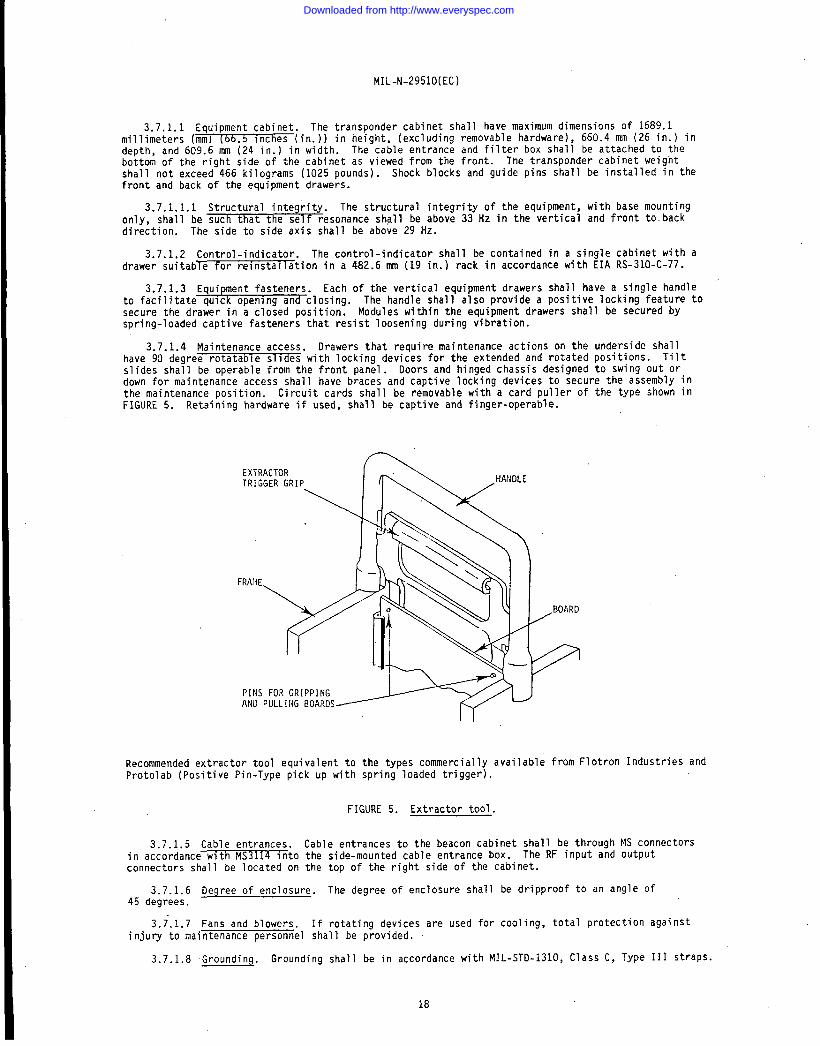
3.7.1.4 Maintenance access. Drawers that require maintenance actions on the underside shal1have 90 degree rotatable slides with locking devices for the extended and rotated positions. TiltS1ides shal1 be operable from the front panel . Ooors and hinged chassis designed to swing out ordown for maintenance access shall have braces and captive locking devices to secure the assembly inthe maintenance position. Circuit cards shall be removable with a card pullerFIGURE 5. Retaining hardware if used, shall be captive and finger-operable.
of the type shown in
EXTRACTORTRIGGER GRIP
\
h. \ .HA’”LE
/BOARD
9
Recommended extractor tool equivalent to the types commercially available from F’otron Industries andProtolab (Positive Pin-Type pick up with spring loaded trigger).
FIGURE 5. Extractor tool.
3.7.1.5 Cable entrances. Cable entrances to the beacon cabinet shal1 be through MS connectorsin accordance with MS3114 into the side-mounted cable entrance box. The RF input and outputconnectors shall be located on the top of the right side of the cabinet.
3.7.1.6 Degree of enclosure. The degree of enclosure shall be dripproof to an angle of45 degrees.
3.~.l.7 Fans and blowers. If rotating devices are used for cooling, total protection againstinjury to maintenance personnel shall be provided.
3.7.1.8 Grounding. Grounding shall be in accordance with MIL-STD-131O, Class C, Type 111 straPS.
18
Downloaded from http://www.everyspec.com

MiL-H-29510(EC)
3.8 Airborne and structureborne noise. The requirement for airborne andshall be ~or Grade A, Type 3 equipinent in accordance dth hilL-STO-740.
structureborne noise
3.9 Safety. Safety shal1 be in accordance wfth the Safety criteria paragraph of MIL-E-L6400.
3.10 Leakage current. The leakage current of the navigational set shall not exceed 5 MA.
3.11 Electrumaqnetic compatibility (EMC) characteristics. The navigational set shal1 confotm tothe Class 7t4 requlrements of M~ except that the EIJ2 transmitter frequency (fo) ?evel isrelaxed by 35 dB. 141L-HDBK-241 &y be u~ed for guidance in electromagnetic interference reduction inpower supply design.
3.12 Identification and markinq. All panel marking shall be engraved.
3.13 Reliabili& The specified mean-time-between-failure (14TBF) (O1 as definedby r41L-STD-/W}
3.14 #laintainabilit~. The navigational set shall have an equipment regain time (ERT) notexceeding =m~nutes when repair is accomplished at the organizational level of maintenance byreplacement of faul~ modules (including printed circuit boards (PCBS)) and chassis-mounted parts(electnnic, electrical, electromechanical, and mechanical parts). The corrective maintenance timeincludes localization, isolation, dtsa$sembly, interchange, reassembly, and checkout for allrcaintenance tasks. The ERT for piece-part repa$r of repairable modules at the intemedfate or depotlevel of maintenance shall not exceed 120 minutes. The organizational level maintainabilityrequirements shall be based on thecapabilities (skill level and experience) of a Navy ElectronicsTechnician, third class (ET-3) in accordance with MAVPERS 12068.
3.14.1 Maintenance concept. The maintenance concept for the navigational set at the user levelis for repair by replacement at the module level utflizing thebuilt-in-test and indication features,the module and chassis test points, and GPTE. Factory only adjuswents shall not exist.
3.14.2 Test measurement and diagnostic equipment ~TMDE) (see 6.4.6). Testprovisions for theequipwsnt shall conform to t41i.-STD-W4, Requirement 32, except as specl~ied herein.
3.14.2.1 Test pofnt criteria, Except for ship testing, test points shall be accessible with theremoval of not more than one cover panel while the equipment is operational and without removal ofcables or connectors. The use of extenderboards is permitted to allow access to test points onprinted circuit cards. Test points shall be provided for the requirements specified in a through e.[Multiple use of test points is permitted and unintentional grounding of test points shall not causedamage to the equipment. )
. Signal quality and cfrcuit performance. Test po~nts, test jacks, or both, shall beprovided to pe%it the injection of signals and the monitoring of signals at the fnpat/Ot$tpUt (1/0)terminals of the system (see 6.4.5), each unit, and each assembly (see 6.4.3).
b. Alignment. Test points, test jacks, or both shall be provided toenergize, injecta standard dynamfc signal, or monitor the intermediate circuft affected by the alignment. Where TlfDE$s used to align or adjust a system, unit, assem~ly, and subassembly (see 6.4.2) circuitry shall bedesignea so that a technic-ian may see and operate the TMDE while making adjustments and probing thecircuit under test.
c. Fault isolation. Test points, test jacks, or both, shall be provideo to permit theinjection and measurement of signals at.1/0terminals of the unit, assembly, and subassembly todetemine satisfactory operation or malfunction of the unft, assembly, or subassembly.
d. Shop testing. Shop t.est$ng of assemblies and subassemblies shall be performed withthe assemblies and subassemblies removed from the prfme equipment. Test points shall be provided sothat the assembly mm.y be activated (such as direct current (OC) and dynamic signals applied), checkedfor quality of operation, and fault isolated to the shop replaceable item (that is, flatpack, voltagecontrolled oscillator, mixer, detector, multiplier, and so forth). Assembly and subassembly testpoints shall be provided in a sfngle connector. Assembly and subassembly test points may be placedat various nodes or locations on the assembly and subassembly.
Standard test jacks. The standard test jacks specified in 1 through 4 shall beprovided asa ~infmum:
19
Downloaded from http://www.everyspec.com

MIL-N-2951O(EC)
Detected RF output (composite signal );: Sync (main trigger)3. Receiver output (video)4. Coder output (video)
3.14.2.2 General purpose electronic test equipment (GPETE). GPETE for use at al1 leve’maintenance shal1 be selected from the standard and substitute standard GPETE 1isted inMIL-STO-1364. The procedures of MIL-STO-1387 shal1 apply when the GPETE 1isted in MIL-STD-not produce a satisfactory test.
s of
364 wil 1
The need for special tools (see 6.4.7) shall be kept to a minimum. Ifrequ?;i~l’i.~ecwil be supplied with each equipment, shall be in accordance withMIL-STO-454, Requirement 63, and shal1 conform to the storage and operating environmental conditionsspecified for the prime equipment.
3.15 Workmanship. Workmanship shall be as specified in 3.15.1 and 3.15.2.
3.15.1 General workmanship. Workmanship shall be as specified in MIL-STD-454, Requirement 9.
3.15.2 Workmanship screen. Navigational sets shal1 withstand a defect detection vibrationscreen of random vibration of 0.02g2/Hz *3 dB from 350 Hz to 2000 Hz, with a rol1-off of 3 dB peroctave starting at 350 Hz, conducted as specified in 4.8.2, and temperature cycling as specified in4.8.1 and 4.8.3.
4. QUALITY ASSURANCE PROVISIONS
4.1 Responsibility for inspection. Unless otherwise specified in the contract or purchaseorder, the contractor Is responsib le for the performance of all inspection requirements as specifiedherein. Except as otherwise specified in the contract or purchase order, the contractor may use hisown or any other facil ities suitable for the performance of the inspection requirements specifiedherein, unless disapproved by the Government. The Government reserves the right to perform any ofthe inspections set forth in the specification where such inspections are deemed necessary to assuresupplies and services conform to prescribed requirements.
4.1.1 Responsibility for compliance. Al1 items shal1 conform to al1 requirements of Section 3and Section 5. he inspection set forth in this specification shall become a part of thecontractor’s overall inspection system or quality program. The absence of any inspectionrequirements in the specification shall not relieve the contractor of the responsibility of assuringthat all products or supplies submitted to the Government for acceptance comply with all requirementsof the contract. Sampling in quality conformance does not authorize submission of known defectivematerial , either indicated or actual , nor does it cormnit the Government to acceptance of defectivematerial .
4.1.2 Government verification. All quality assurance operations performed by the contractorwill be subject to Government verification at any time. Verification will consist of, but is notlimited to, a) surveillance of the operations to determine that practices, methods, and procedures ofthe written quality program are being properly applied, b) Government product inspection to measurequality of the product to be offered for acceptance, and c) Government inspection of deliveredproducts to assure compliance with all inspection requirements of this specification. Failure of thecontractor to promptly correct deficiencies discovered by him or of which he is notified shall because for suspension of acceptance until corrective action has been taken or until conformance of theproduct to prescribed criteria has been demonstrated.
4.1.3 Quality assurance terms and definitions. Quality assurance terms used in thisspecification shall be as defined in MIL-STD -109.
4.2 Classification of inspections. The inspection requirements specified herein are classifiedas specified in a through d:
a. First article inspection (see 4.3)b. Quality conformance inspection (see 4.4)
Production inspection (Group A) (see 4.4.1)~1 Production control inspection (Group B) (see 4.4.2)3. Environmental inspection (Group C) (see 4.4.3)
c. Safety verification (see 4.5.2)d. Inspection of preparation for delivery (see 4.1O)
20
Downloaded from http://www.everyspec.com

MIL-M-2951O(EC)
4.3 First article inspection. Unless otherw$se specffied (see 6.2), one single and one dualnavigational set shall be required for ffrst article inspection. First article inspection shal 1consist of al1 examination and testing necessary to detem$ne conformance with the requirements ofthis specification. First article inspection shall fnclude the examination and testing specified inTABLE lV and the performance tests specified fn TABLE V, Groups A, B, and C. The total testrequirements for first article inspection my be proportioned over the contract”s first articles,subject to approval of the procuring activity.
TABLE IV. Examination and test.
Quality conformanceFirst inspection
iZxamination Requirement Test article Group Group Groupor test paragraph paragraph inspectf on A b c
Surface examinationbfeight 3.7.1.1 4.5 xQirx3nsions 3.7.1.1 4.5 xParts 3.4.1 4.5 xPainting 3.4.2.1 4.5 xIdentificationand marking 3.12 4.5 x
Safety 3.9 xGeneral workmanship 3.15.1 x
Performance TABLE V x ; x xTemperature
sequenceLow temperature 4.5
:::x x
High temperature 4.5 x xiiumiaity 4.5
Hx x
Salt fog [spray] 4.!5 x xShock 3.5 4.5 xVibration 3.5 4.5
x
Enclosure 3.7.1. b 4.5 x xSteady-state voltage
and frequency 3.6.1 4.5 x xTransient voltage 3.6.1 4.5 x xTransient frequency 3.6.1 4.5 x xSpike voltage 3.6.1 4.5 x xPower interruption 3.6.1 4.5 x xPower and power
factor 3.6.1 4.5Leakage curren~ 3.10 4.5.3 i.EKE
x3.11 4,5.4 x x
Maintainability 3.14 4.7~1 xReliability 3.13Thermal survey
4.64.5.1 AI :
Airborne andstructureborne noise 3.8 4.5 x
At Required on original development contract only.
4.4 Quality conformance inspection. ouality conformance inspection shall be performed asspeciffed In 4.4.1 through 4.4. J.3.
4.4.1 Production inspection (Group A]. Production inspection shall be conducted on eachnavigational set ottered tor dellvery. l%e inspection shall comprise examinations and tests whichwill prove the workmanship and reveal the omissions and errors of the production process such asfunctional and performance tests at a limited nwzber of points, tests which detect deviations fromdesign, tests of controls and adjustments, and tests which detect hidden defects of material.production inspection shall include the examinations and tests of TABLE IV, Group A, and theperformance tests specified in TJWLE V, Group A.
4.4.2 Production control inspection (Group B). Production control inspection shall be performedon a randody selected samp?e from each month’s production lot and shall include examinations andtests of ?AML.t IV, Group 8, and the performance tests specified in TABLE V, Group Il. productioncontrol inspection shall be performed on navigational sets that have passed production inspection.The sample shall satisfactorily complete the production control inspection prior to release of themonth’s production to shipment.
Downloaded from http://www.everyspec.com

MIL-N-2951CI(EC)
TABLE V. Performance tests.
Quality conformanceinspection
Requirement Group Group GroupTests paragraph A B c
—
Peak power out 3.3.2.2.6 xRF pulse spectrum 3.3.2.2.7.2 xPulse shape 3.3.2 .2.7.1 xPulse droop 3.3.2 .2.7.3 xFrequency stability 3.3.2 .2.7.5 xCw output 3.3.2 .2.7.4 xPulse coding 3.3.1 xSquitter rate 3.3.2.1.10 xDemand tolerances 3.3.2.1.3 xSquitter distribution 3.3.2.1.14 xReceiver bandwidth 3.3.2.1.4 xEcho suppression 3.3.2.1.9 xReceiver selectivity 3.3.2.1.5 xSingle pulse rejection 3.3.2.1.6Narrow pulse interference 3.3.2.1.12 xCW interference 3.3.2.1.11 xResponse delay 3.3.2.1.7 xTriggering level 3.3.2.1.2 xDead time 3.3.2.1.8 xReceiver decoding 3.3.2.1.6 xMonitor tolerances 3.3.3.2 x
BITEii tolerances 3.3.5 xControls and interlocks (beacon) 3.3.6 xControls and interfaces 3.3.7 xInterface (antenna) 3.3.2.2.1.3,
3.3.6.2.1 xPretrigger tolerances 3.3.1.1.6 xAncillary interface 3.3.& x
~/ Built-in-test equipment (see 6.4.1)
4.4.3 Environmental inspection (Group C). Environmental inspection shall be as specified inTABLE IV, Group C, and the performance tests specified in TABLE V, Group C and shall be performed onunits which have been subjected to and have passed production inspection. Vibration testing from33 Hz to 50 Hz shall be limited to a single sweep search for resonance at a reduced magnitude.
4.4.3.1 Sampling for environmental inspection. The initial sample shall be selected from thefirst month’s production lot, and shall satisfactorily complete environmental inspection prior torelease to shipment of the second month’s production lot. Subsequently, one each sample shall beselected from each successive 25 navigational sets, or fraction thereof, and shall pass environmentalinspection prior to release to shipment of succeeding month’s production quantities.
4.4.3.2 Nonconforming environmental sample units. If a sample unit fails the inspectionspecified in 4.4.3 , the contractor shall immediately investigate the cause of failure and shallreport to the quality assurance representative (QAR) the results thereof and details of the”corrective action to be taken to correct units of product which were manufactured under the sameconditions, with the same materials, processes, and so forth. The contractor shall demonstrate theeffectiveness of the corrective action to the QAR by subjecting two additional navigational sets tothe failed environmental inspection. In the case of the humidity test, only the two additionalcorrected cards and modules or components shall be subjected to the same number of hours and
22
Downloaded from http://www.everyspec.com

PIIL-N-29510(EC)
conditions as for the system test. lfthecontractor cannot demonstrate effective corrective actionthat enables the equipment to conform to speciffed requirements, or if the cause of failure cannot bedetenairted, the matter shall be referred to the contracting officer.
4.4.3.3 Reinspection of conforming environmental sample units. Unless othemise specified inthe contract ~see 6.2), sample units which have been $uixjected to, and have passed, environmentaltests may be accepted on the contract, provided they are resubjected to, and pass, productioninspection after repair of all damage.
4.5 Test methods. Examtnatfons and tests specfffed in TABLE IV and ‘TA3LE V shall be conductedto verify conformance to applicable specification requirements and as specified in 4.5.1 through4.5.4.
4.5.1 Thermal surve~“
To verify the system design portion of 3.6a, the contractor shall conducta complete t enna survey of the navigational set during temperature environmental testing, todetermine the existence of hot spots which may prove to be injurious to the useful life of thesystem. The survey shall be conducted with the system packaged and enclosed in the proposed finalproduction configuration. The survey shall inc]ude a thermal profile of the fnternal configurationof the system and all critical ?tems at both 25,C ambient and the maxlmm specified ambient operatingtempera ture. The survey shall be completed and all required corrective measures taken by thecontractor prior to approval by the procurtng activity. A hot spot is any item Ipart or assembly ofparts) used in the system including, but not limited to, semiconductor devices, printed circuit”boards (PC3S), transformers, and resistors which attatn a temperature in excess of that recoannendedby the $tem manufacturer or applicable specification, or an assembly of parts that attain atemperature which could cause accelerated degradation of the system. The thermal survey shall berepeated whenever system changes occur which may affect this characteristic.
4.5.2 Safety verification. Examinations, analyses, and tests shall be performed to verifyconformance to 3.9.
4.5.3 Leakage current test. The leakage current test shall be performed as specified in 4.5.3.1and 4.5.3.2.
MARWING
THIS TEST MAY BE HAZARDOUS DUE TO THE UNGROUh!DED COMOITIOM OFTHE NAV1GATIOML SET OURING THE ‘TEST. 00 NOT TOUCH EXPOSEOMETAL suRFAcEs UITHOUT ADEQUATE ELECTRIC smcx PRoTECTION.
THE U141TE0 STATES GOVERNMENT NEITHER ASSUMESNOR ACCEPTS RESPOMSIBILITYFOR ANY INJURY OR OAJAAIiETNAT MAY OCCUR OURING OR AS A RESULT OF THIS TEST.
4.5.3.1 Navigational set connections. Each navigational set dfrectly connected to an externalpower source and units deriving power from the navigational set shall be placed on an insulatedsurface. All safety ground conductors between the navigational set and units deriving power frmn thenavigational set shall be intact. The safety qround conductor between the navigational set and thesource power shall be opened during the test. The navigational set shall be connected as shown inFIGURE 6 if it ts connected to single-phase source power,
4.5.3.2 Measurement. Leakage current shall be measured on the navigational set in its normaloperating configuration. Navigational set controls in each operating mode shall be such that maximumpower will be utilized during leakage current measurements. The leakage current shall be determinedby the voltage-drop method. A true root-mean-square (rms) vollxxeter shall be used. The voltagemeasured across the 1500-ohm resistor shall not exceed 7.5 V at the highest nominal power linevoltage and the highest and lowest nomfnal power line frequencies for which the navigational set isdesigned. The overall measurement error shall not exceed 5 percent.. The probe shall be used on allexternal conducting parts such as case, connector housings, recessed calibration or adjustmentcontrols, and cont;ol shafts with knobs rentoved, and the-voltage measured for every combination ofswitch positions available ininsnediately after the test is
4.5.4 EMC test. Conformanceaccordance with MIL-STO-462.
FIGURE 6. The opencompleted.
to the requirements
safety ground conductor shall be reconnected
of 3,11shall be verfffed by tests performed in
23
Downloaded from http://www.everyspec.com

REV
ERSI
NG
SWIT
CH
NORMAL-
REVERSED
INSULATED
m?GENERAL
ORDER
OFTEST:
,Jq
=+O
N-O
FFSW
ITC
H
21
y–-
--1TR
UE
1.So
urca
pow
erO
FF.
Cor
rnec
teq
ulcl
-m
errt
per
dlog
rom
.d
LOA
Do.
15pf
‘soo
nv
?%T-
2.O
N-O
FFSW
OFF
.S
1S
Wnormol.S2
..—.
METER
SWclosed.Connect
source
power.
SAFETY
GROUND
ISA
FETY
GR
OU
ND
SWIT
CH
INSU
LATE
DSU
RFA
CE
WA
RN
ING
DO
NO
TTO
UC
HEX
POSE
DM
ETA
LSU
RFA
CES
THIS
TEST
MA
YB
EH
AZA
RD
OU
SD
UE
TOTH
EU
NG
RO
UN
DED
CO
ND
ITIO
NO
FTH
EEQ
UIP
-M
ENTD
UR
ING
THE.
TEST
.TH
EU
NIT
EDST
ATE
SG
OVE
RN
MEN
TN
EITH
ERA
SSU
MES
NO
RA
CC
EPTS
RES
PON
SIB
ILIT
YFO
RA
NY
INJU
RY
OR
DA
MA
GE
THA
TM
AY
OC
CU
RFR
OM
THE
USE
OF
TH19
DIA
GR
AM
FOR
LEA
KA
GE
CU
RR
ENT
MEA
SUR
EMEN
T.
3.[o
BSE
RVE
WA
RN
INQ
jS
2S
Wo
PE
N.
ON
-OFF
SWO
N.
4.Fo
reo
chpr
obe
poin
t,ra
cord
vol-
tmet
erre
odln
g(C
ASE
CO
NN
ECTO
RS}
-C
ON
TRO
LS,
SHA
FTS)
.5.
ON
-OFF
S“W
OFF
.R
eoea
tSt
ev4,
6.S1
SWR
EVER
SED
.“
“O
N-O
FFSW
ON
.R
epea
tSt
ep4.
7.O
N-O
FFSW
OFF
.R
epea
tSt
ep4.
8.S2
SWC
LOSE
D.
SISW
norm
al.
9.R
epea
tSt
ep3
THR
U8
for
each
mod
eof
oper
atio
n.lQ
Rem
ove
sour
cepo
wer
.D
mco
nnec
teq
uipm
ent.
Sign
reco
rdsh
eet.
FIG
UR
E6.
Sing
le-p
hase
test
diag
ram
for
leak
age
curr
ent
mea
sure
men
t.
Downloaded from http://www.everyspec.com

..
MIL-M-2951O(EC)
4.6 Reliability qualification test (RQT). An RQ? shal 1 be conducted in accordance with thegeneral requirements of kl~ -S?0- 781 Test Plan XXIC. Testing shall proceed to a decision inaccordance with accept or ~ject cri&ia of Test Plan XXIC.
4.6.1 RQT conditions. The navigational sets shall be subjected to the environmental conditionsof 141L-STD-781 , equipment Category 3A anti the Test conditions matrix table of MIL-STD-781.
4.6.2 Re ection-+=--”
If the test results in a reject decision, the procuring activity shall beimmediately notl led. The contractor shall, at no costto the Government,
a) rerun the entire RQT, orb) rerun portions of the RQT to vertfy the effectiveness of the corrective action
developed to remedy causes for the rejectfon. Successful demonstration of corrective actfons withoutadditional failures shall be a basis for hardware acceptance.
4.6.3 Failure. The final decfsion as tothedefinition and classification of failures shall bemade by the procur$ng itctivity, using the Failure categories paragraph of MJL-STD-781 as a guide.Amy operating discrepancy or degradation that requires an unscheduled adjustment or calibration to bemade after initial satisfactory operation of the navigational set sh~ll be defined as a failure.
4.7 Maintainability demonstration. Conformance with the equipment and module” maintainabilityrequirements shall be demonstrated in accordance wfth 141L-STO-471, Test Method 4. Only Phase 11 ofNIL-STD-471 shall apply.
4.7.1 Equipment maintainability. The equipnent maintainability demonstration shall consist of20 corrective maintenance tasks requfring replacement of modules (or PC3S) or chassis-mounted partsat the organizational level of maintenance. Fifty faults shall be determined for the equipmentmaintainability demonstration in accordance with APPENDIX A of MIL-STO-471. The procuring activityor its representative shall select 20 of these faults to be used in this part of the maintainabilitydemonstration. For fault simulation, a number shall be assigned to each component and part within amodule or chassis-mounted component and part. Fault simulation for modules shall be accomplished byintroduction to faulty parts corresponding to the number selected or by simulating such faults. Aspart of tttedemonstration, the accessibility shall be observed to determine conforntance with 3.14.
4.7.2 Module maintainability. The module maintainability demonstration shall consist of 20corrective ma~ntenance tasks requiring repair of modules (or PCBS) by replacement of parts at theintermediate or depot level of maintenance, as appropriate. A minimum of two faults shall bedetermined for each repairable module, Fault selection and simulation for each repairable moduleshall be in accordance with the procedure for the equipment maintainability demonstration, Using thelist as a guide, a total of 20 faults shall be selected by the procuring activity for the modulemaintainability demonstration.
4.7.3 Technicians. ‘The procurtng activity reserves the right to provide and select thetechnicians to perform the equipment maintainability demonstration. The module maintainabilitydemonstration shall be performed by contractor personnel.
4.7.4
4.7. saoti fied.
repeat the
Technical documentation. Technical documentation shall be limfted to the technical manual.
Rejection. If a reject decisfon is reached, the procuring activity shall be immediatelyThe contractor shall, at no additional cost to the Government:
a. Oevelop an approach for redesign or correction of all deficiencies, andb. Upon approval of an approach to the redesign or corrections, the contractor shalldemonstration until an accept decision is reached.
4.8 Workmanship. Workmanship shall be as specified in 4.8.1 through 4.8.4.
4.8.1 General workranshig. The nav$gationa? set shall be examined to determine conformance tothe requirements of 3.15.1.
4.8.2 $forkm!mship screen. Workmanship screen shall consist of the three segments specified in athrough c:
a. Nonoperating temperature cycling at the subassembly level. All modules shall besubjected to nonoperating temperature cycling.
b. Randomvibration at the system level. One navigational set from each third month’sproduction shall be subjected to random vibration screening.
25
Downloaded from http://www.everyspec.com

c. Temperatureshal1 be conducted on each
MIL-N-2951O(EC)
cycling at the system level. Temperature cycling at the system levelsystem.
4.8.2.1 Nonoperating temperature cycling at the subassembly level. Subassemblies shall becategorized as nonhybrid and hybrid as speclfled In 4.8.2 .1.1 and 4.8.2.1:2. High voltage powersupply potted modules shal1 not be subjected to nonoperating temperature cycling.
4.8.2.1.1 Nonhybrid facility assemblies. Nonhybrid facility assemblies shall be as specified ina through f:
Two chambers shal1 be used to conduct thermal shock tests. One chamber shal1 beset at -54~C, h~~einafter referred to as CO1d chamber, and one chamber shal1 be set at +1OO!C,hereinafter referred to as hot chamber.
b. Thermal shock shal1 be conducted chamber to chamber, with minimum dwel1 timebetween chambers.
c. The unit under test shall be placed in the cold chamber and shall remain for1 hour.
d. After 1 hour i n the CO1d chamber, the unit under test shal 1 be removed and placedin the hot chamber and remain for 1 hour.
e. Procedures c and d, run sequentially as specified herein, complete one cycle ofthermal shock.
f. Twenty-five cycles shall be conducted on each unit under test.
4.8.2 .1.2 Hybrid facility assemblies. Hybrid facility assemblies shall be as specified in athrough c:
Two chambers shall be used to conduct thermal shock tests. The cold chamber shall“be set at -28~Ca~nd the hot chamber shall be set at ‘90°C.
b. Procedures b through d, run sequentially as specified in 4.8.2.1.1, complete onecycle of thermal shock.
c. Fifteen cycles shall be conducted on each unit under test.
4.8.3 Vibration. Following the subassembly nonoperating temperature cycling, and prior toconducting temperature cycling at the operating cabinet level, vibration shall be performed. Thevibration shall be random, or, subject to procuring activity approval, pseudo-random or complexwaveform vibration for an accumulated time of 10 minutes in the top to bottom direction on theOX-52/URN and in the front to back direction on the C-10363/URN. All test items shall behard-mounted (without shock isolators) and subjected to the vibration conditions specified herein.The control accelerometer shall be located next to one of the mounting points of the item undertest. Navigational sets having a bandwidth no greater than 10 Hz for vibration frequencies up to500 Hz and 100 Hz for vibration frequencies above 500 Hz shall be used for the control and analysisof the acceleration spectral density. The test item shall be energized during vibration. Failuresoccurring during vibration shall be corrected and the test resumed. If random vibration testing isconducted at a facility remote to the contractor’s plant, only failures related to loss of operatingvoltages shall be corrected on site. Any remaining failures may be corrected after return to thecontractor’s plant. Failures occurring in the sample navigational sets shall be localized andidentified so that all other like navigational sets produced that month may be examined or tested forthe presence o.flike defects.
4.8.4 Temperature cycling at the system level. Following vibration, if applicable, eachnavigational set shall be subjected to the temperature cycle shown in FIGURE 7. The temperature rateof change shall be not less than 5~C per minute. Navigational set power shall be turned on and offat the indicated times. When practical, navigational set drawers, panels, and enclosures shall beopened or removed for maximum exposure to the changing temperature. Cooling blowers within thenavigational set may also be operated when the navigational set is turned off. When a test is calledfor, a functional operating test shall be performed. The dwell time for each cycle shall be80 percent of the time required for the largest electrical or electronic part to become temperature-stabilized. Temperature stabilization shall be as defined in MIL-STO-81O for the nonoperatingcondition. When test failures occur, the navigational set shall be reworked and the cyclingcontinued for a cumulative total of six cycles.
26
Downloaded from http://www.everyspec.com

141L-N-29510[EC)
1
— —“
CQWLfTL SY$lEN 10?t’ltWIUliL l.Vl.Ll<
.
I
L
FIGURE 7. Temperature cycle at the system level.
4.9 Manufacturingrun-in.Followingworkmanship screen, each navigational set shall besubjected to a Manufacturing run-fn. This test shall consist of at least 40 operating hours atambient temperature with the last 24 hours failure-free.
4.10 lnspect~on of preparation for del$very, Inspection shall be performed to ensureconformance with the requirements of SectIon 5.
27
Downloaded from http://www.everyspec.com

MIL-N-2951O(EC)
5. PACKAGING
(The preparation for delivery requirements specified herein apply only for direct Governmentprocurements. Preparation for delivery requirements of referenced documents 1istealin Section 2 do’not apply unless specifically stated in the contract. Preparation for deli very requirements forproducts procured by contractors shal1 be specified in the individual order. )
5.1 Preservation, packaging, packing, and marking. Unless otherwise specified herein,preparation for delivery shal1 be In accordance WIth the appl icable levels of preservation,packaging, packing, and marking specified in MIL-E-17555 (see 6.2).
6. NOTES
6.1 Intended use. The navigational set, covered by this specification, is intended to beinterfaced with a family of TACAN antennas for service on ship or shore facilities. The navigationalset will provide distance, azimuth, and identification information to aircraft with properly equippedinterrogators.
6.2 Ordering data. Procurement documents should specify:
a. Title, number, and date of this specificationb. Number of first article samples to be submitted if other than specified in 4.3c. When reinspected environmental sample units may not be accepted (see 4.4.3.3)d. Applicable levels of preservation, packaging,, packing, and marking (see 5.1)
6.3 First article. When a first article inspection is required, the item(s) should be a firstarticle sample. The first article should consist of one single and one dual navigational set. Thecontracting officer should include specific instructions in acquisition documents regardingarrangements for examinations, approval of first article test results and disposition of firstarticles. Invitations for bids should provide that the Government reserves the right to waive therequirement for samples for first article inspection to those bidders offering a product which hasbeen previously acquired or tested by the Government, and that bidders offering such products, whowish to rely on such production or test, must furnish evidence with the bid that prior Governmentapproval is presently appropriate for the pending contract.
6.4 Definitions. Definitions of terms used in this specification are given in 6.4.1 through6.4.8.
6.4.1 BITE. Instruments, devices (electrical, electronic, mechanical, magnetic, or chemical,and so fort~tools and interface equipment, built as an integral part of the equipment and usedto: test, observe, measure, monitor, modify, generate, calibrate and control physical properties,movements, and other characteristics. This includes power sources, modifiers, scalers, jigs,templates, monitoring devices, plumbing standards, and programming software required to test,measure, and diagnose.
6“4”2v“ Two or more parts which form a portion of an assembly, but having partswhich are lndlvldual y replaceable (such as, modules and PCBS with components).
6.4.3 Assembly. A number of parts or subassemblies or any combination thereof, joined togetherto perform a specific function and capable of disassembly (such as, audio oscillator, amplifier,synthesizer, crystal oscillator).
6.4.4 Unit. An assembly or any combination of parts, subassemblies, and assemblies niountedtogether, n=lly capable of independent operation in a variety of situations. For the purpose ofthis specification, the following items are units: Each base station equipment, that is, interfacecentral unit, system control unit, RF repeater, remote monitor unit; also portable equipmentincluding protective communications helmet, transceiver electronics, F/P transceiver, F/V chargeramplifier, damage control adapter, and support equipment including the cryptovariable fill unit, andbattery charger.
6.4.5 System. All possible combinations of units required to perform a function.
6.4.6 TMOE. TMOE are all instruments, devices (electrical, electronic, mechanical, magnetic, orchemical,, a=o forth), tools and interface equipment used to: test, observe, measure, monitor,modify, generate, calibrate and control physical properties, movements, and other characteristics.This includes power sources, modifiers, scalers, jigs, templates, monitoring devices, waveguides,standards, and programming software required to test, measure, and diagnose.
28
Downloaded from http://www.everyspec.com

MIL-M-2951O[ECJ
6.4.7 .~. Special t OOIS are defined as those tools not 1 isted in the National SupplyCatalog [copies o t 1s catalog may be consul ted in the office of the Defense Contract AdministrationService).
6.5 Refurbishing first artfcle units. After first article approval, first art$cle units shouldbe refurb~shed and should pass the production inspection tests.
6.6 Subject term [keyword) listin~.
Antenna tuning triggersAN/llRt&25, navigational setAuxiliary reference pulse groupDistribution statement AElectromagnetic compatibility (EMC)fieneral purpose electronic test equipment (GPETEILeakage currentMain reference pulse groupMaintainabilityNavigational set, AN/URA-25Noise airborne and structurebornePretriggerPretrigger characteristicsPulse codingReliabilitySafetyTACMTest measurement and diagnostic equipment (TMi)E)Workmanship screen
6.714 June
Supersessiondata. This specification includesthe requirementsof ELEX-T-2385),datedlm3 .
Preparing activity:NAVY - EC
(Project No. S825-N020(EC))
29
Downloaded from http://www.everyspec.com