Embed Size (px)
Citation preview

AFQTP 3E3X1-25 31 JANUARY 2003
AIR FORCE QUALIFICATION TRAINING PACKAGE (AFQTP)
FOR
STRUCTURAL (3E3X1)
MODULE 25
PERSONNEL DOOR AND WINDOW MAINTENANCE
AFQTP 3E3X1-25
TABLE OF CONTENTS
MODULE 25
PERSONNEL DOOR AND WINDOW MAINTENANCE
AFQTP GUIDANCE INTRODUCTION..............................................................................................25-3
AFQTP UNIT 1 INSTALL PERSONNEL DOOR UNITS
WOOD (25.1.1.)................................................................................................25-4 METAL (25.1.2.) .............................................................................................25-11
AFQTP UNIT 2 REPAIR PERSONNEL DOOR UNITS
WOOD (25.2.1.)..............................................................................................25-17 METAL (25.2.2.) .............................................................................................25-24
AFQTP UNIT 5 PERSONNEL DOOR HARDWARE
INSTALL DOOR CLOSERS (25.5.1.).............................................................25-31 CYLINDER LOCKS (25.5.3.1.).......................................................................25-39 PANIC HARDWARE/EXIT DEVICE (25.5.3.4.) ..............................................25-46 INSTALL HINGES (25.5.3.5.).........................................................................25-53
REVIEW ANSWER KEY.......................................................................................................KEY-1
CORRECTIONS/IMPROVEMENT LETTER ............................................................ APPENDIX A
Career Field Education and Training Plan (CFETP) references from 1 August 2002 version.
OPR: HQ AFCESA/CEOF Certified by: HQ AFCESA/CEOF (SMSgt Dan Sacks) (CMSgt Myrl F. Kibbe) Supersedes AFQTP 3E3X1-24, 14 Jul 00 Pages: 65/Distribution F
Notice. This AFQTP is NOT intended to replace the applicable technical references nor is it intended to replace hands-on training. It is to be used in conjunction with these for training purposes only.
25-2
AFQTP 3E3X1-25
AIR FORCE QUALIFICATION TRAINING PACKAGES
FOR STRUCTURAL
(3E3X1)
INTRODUCTION
Before starting this AFQTP, refer to and read the “AFQTP Trainer/Trainee Guide”
AFQTPs are mandatory and must be completed to fulfill task knowledge requirements on core and diamond tasks for upgrade training. It is important for the trainer and trainee to understand that an AFQTP does not replace hands-on training, nor will completion of an AFQTP meet the requirement for core task certification. AFQTPs will be used in conjunction with applicable technical references and hands-on training. AFQTPs and Certification and Testing (CerTest) must be used as minimum upgrade requirements for Diamond tasks.
MANDATORY minimum upgrade requirements: Core task: AFQTP completion Hands-on certification Diamond task: AFQTP completion CerTest completion (80% minimum to pass) Note: Trainees will receive hands-on certification training for Diamond Tasks when equipment becomes available either at home station or at a TDY location. Put this package to use. Subject matter experts under the direction and guidance of HQ AFCESA/CEOF revised this AFQTP. If you have any recommendations for improving this document, please contact the Career Field Manager at the address below.
HQ AFCESA/CEOF 139 Barnes Dr. Suite 1
Tyndall AFB, FL 32403-5319 DSN: 523-6445, Comm: (850) 283-6445
Fax: DSN 523-6488 E-mail: [email protected]
Notice. This AFQTP is NOT intended to replace the applicable technical references nor is it intended to replace hands-on training. It is to be used in conjunction with these for training purposes only.
25-3
AFQTP 3E3X1-25 25.1.1.
INSTALL PERSONNEL DOOR UNITS
MODULE 25 AFQTP UNIT 1
WOOD (25.1.1.)
Notice. This AFQTP is NOT intended to replace the applicable technical references nor is it intended to replace hands-on training. It is to be used in conjunction with these for training purposes only.
25-4
AFQTP 3E3X1-25 25.1.1.
INSTALL WOOD PERSONNEL DOOR UNIT
Task Training Guide
STS Reference Number/Title:
25.1.1. – Install wood personnel door unit.
Training References:
1. Career Development Course (CDC) Structural Journeyman 3E351C, Volume 1, Unit 5, Section 5-1; Lesson 037; Installing Exterior Doorframes and Doors and Section 5-2, Lesson 041; Installing Interior Doors.
2. Commercial Manual, Modern Carpentry by Willis H. Wagner, 1992.
3. Navy Advancement Training (NAVEDTRA) Course14044, Builder 3 and 2, Volume 2.
4. Door manufacturer’s instructions.
Prerequisites: 1. Possess as a minimum a 3E331 AFSC. 2. Review the following references:
2.1. CDC Structural Journeyman 3E351C, Volume 1, Unit 5, Section 5-1, Lesson 037 and Section 5-2, Lesson 041. 2.2. Modern Carpentry, Unit 17, Doors and Interior Trim, pg. 424-29 to 434-5. 2.3. NAVEDTRA 14044, Chapter 6, Interior Finish of Floors, Stairs, Doors, and Trim. 2.4. Door manufacturer’s instructions.
Equipment/Tools Required:
1. Personal Protective Equipment (PPE). 2. Basic Tool Kit. 3. Tape Measure. 4. 4’ Level. 5. Framing Square. 6. Hammer. 7. Nail Set. 8. Casing Nails. 9. Finish Nails.
10. Pre-hung Door Unit.
Learning Objective:
Trainee should be able to install a pre-hung wood door within a reasonable time limit as determined by trainer.
Samples of Behavior:
1. Trainee should demonstrate a basic knowledge of doors, components, and installation techniques.
2. Trainee should be able to install a pre-hung door unit. Notes: 1. Any safety violation is an automatic failure. 2. Trainer will have to provide the trainee with a job/work order in order to complete this task.
If job/work order is not available, trainer will have to construct a wall with the rough opening outline in step 2.
Notice. This AFQTP is NOT intended to replace the applicable technical references nor is it intended to replace hands-on training. It is to be used in conjunction with these for training purposes only.
25-5
AFQTP 3E3X1-25 25.1.1.
INSTALL WOOD PERSONNEL DOOR UNIT
1. Background. As a structural journeyman, one of your tasks will involve installing interior/exterior wood personnel door units. These units are very similar in construction. The frames consist of two side jambs and a head jamb and on exterior units a sill is installed at the bottom of the jamb. The units are typically purchased with the doors pre-hung on the jambs; however, this is not always the case. In this unit, we will describe the procedures for installing pre-hung interior and exterior door units. This is a very important task that cannot be taken lightly. Imagine the consequence if a door to a secured area is not installed properly—classified material may become compromised jeopardizing national security. As with all things, remember excellence in all that you do.
2. Door Units. One of the primary considerations that must be made when ordering or constructing a door unit is not only the door size, but the rough opening size as well.
2.1. Consider the door's thickness, height, and width, as well as the wall’s thickness. Door units come in different sizes, the most common size being 3' 0" x 6' 8". Jambs can vary from 4 1/2" to 5 1/4 " in width. However, the most common door unit jamb encountered is 4 5/8" wide for 2” x 4” walls with 1/2" drywall covering.
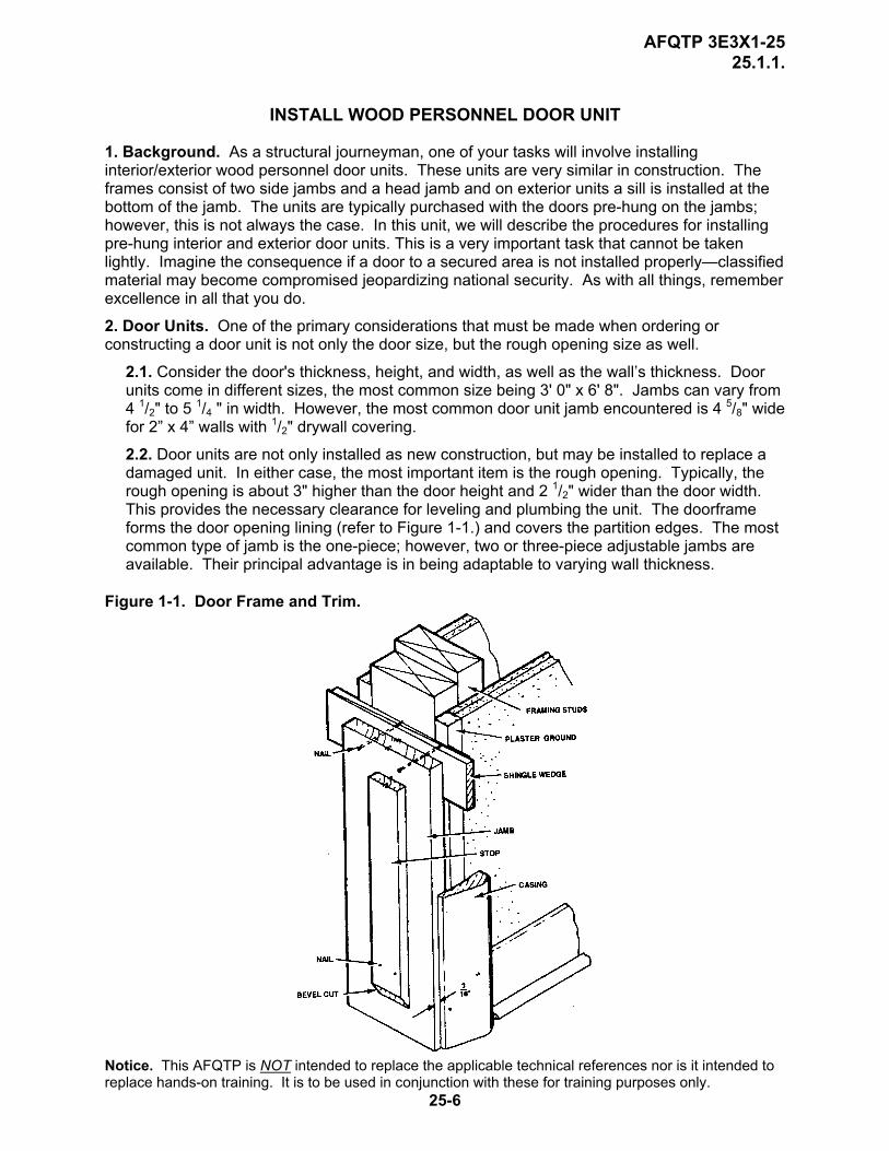
2.2. Door units are not only installed as new construction, but may be installed to replace a damaged unit. In either case, the most important item is the rough opening. Typically, the rough opening is about 3" higher than the door height and 2 1/2" wider than the door width. This provides the necessary clearance for leveling and plumbing the unit. The doorframe forms the door opening lining (refer to Figure 1-1.) and covers the partition edges. The most common type of jamb is the one-piece; however, two or three-piece adjustable jambs are available. Their principal advantage is in being adaptable to varying wall thickness.
Figure 1-1. Door Frame and Trim. Notice. This AFQTP is NOT intended to replace the applicable technical references nor is it intended to replace hands-on training. It is to be used in conjunction with these for training purposes only.
25-6
AFQTP 3E3X1-25 25.1.1.
SAFETY: DUE TO THE SIZE AND WEIGHT OF A DOOR UNIT, A TRAINEE WILL NEED HELP TO SET AND PLUMB A DOOR UNIT.
3. Procedures. Follow these steps to install an interior door unit: Step 1: Gather required tools and materials. Having the proper equipment will save time by preventing you from having to go back to the shop and retrieve additional tools. A general toolbox, along with a 4’ level and/or straight edge and miter saw, will prove most helpful when beginning this type of undertaking.
HINT: Check the door unit size against the Job/Work Order to ensure the correct door was received.
Step 2: Check rough opening size. Ensure rough opening is adequate for the doorframe. Rough openings for interior doors are usually framed to be 3 inches higher than the door height and 2 1/2 inches wider than the door width. This provides enough space for the frame to be plumbed and leveled in the opening.
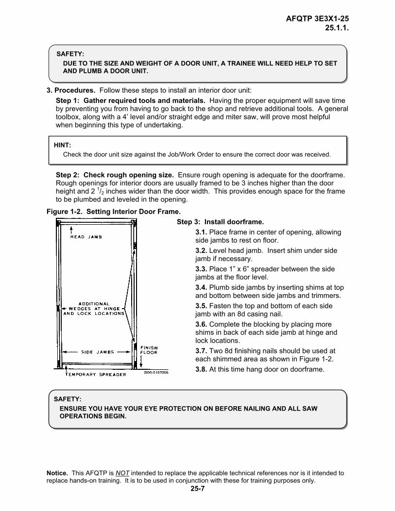
Figure 1-2. Setting Interior Door Frame. Step 3: Install doorframe.
3.1. Place frame in center of opening, allowing side jambs to rest on floor. 3.2. Level head jamb. Insert shim under side jamb if necessary. 3.3. Place 1” x 6” spreader between the side jambs at the floor level. 3.4. Plumb side jambs by inserting shims at top and bottom between side jambs and trimmers. 3.5. Fasten the top and bottom of each side jamb with an 8d casing nail. 3.6. Complete the blocking by placing more shims in back of each side jamb at hinge and lock locations. 3.7. Two 8d finishing nails should be used at each shimmed area as shown in Figure 1-2. 3.8. At this time hang door on doorframe.
SAFETY: ENSURE YOU HAVE YOUR EYE PROTECTION ON BEFORE NAILING AND ALL SAW OPERATIONS BEGIN.
Notice. This AFQTP is NOT intended to replace the applicable technical references nor is it intended to replace hands-on training. It is to be used in conjunction with these for training purposes only.
25-7
AFQTP 3E3X1-25 25.1.1.
NOTE: Hinged doors should open or swing in the direction of natural entry, against a blank wall whenever possible. Doors should not obstruct other swinging doors or hinged to swing into a
HINT: When setting a doorframe, do not fully set any nails until all blocking has been adjusted and the jambs are straight and plumb.
Step 4: Check operation. Observe the spacing between the door and jamb during operation. Open and close the door several times.
4.1. Check the hinge areas for signs of binding against the jamb or stop. 4.2. With the door in the closed position, it should rest freely against all stops. 4.3. Ensure adequate clearance between jambs and door. 4.4. If the door operates properly, set the remaining nails below the surface.
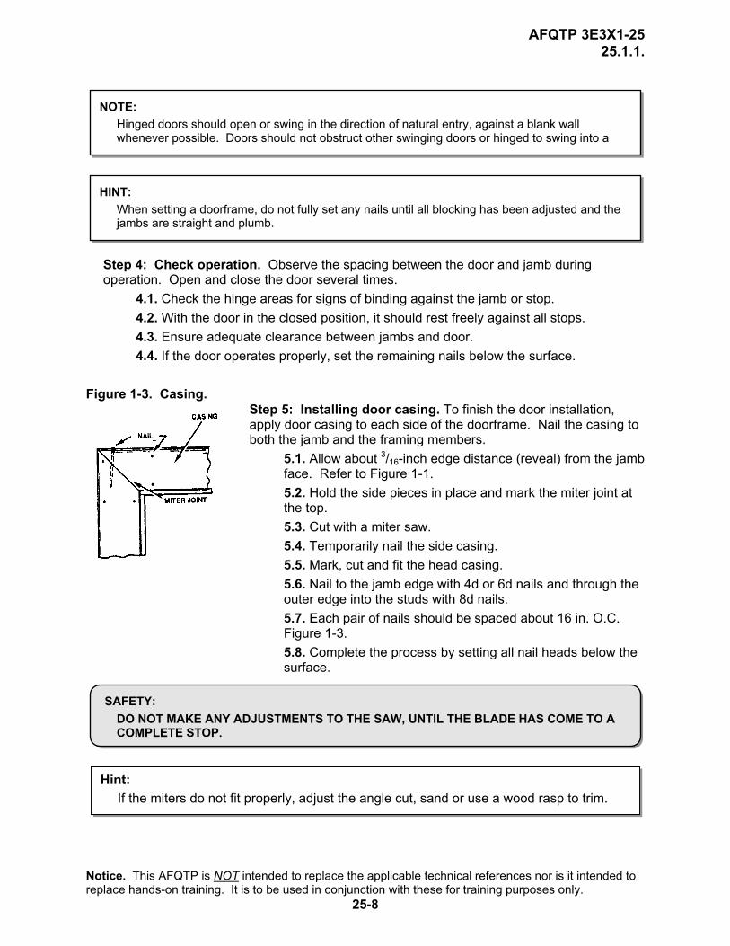
Figure 1-3. Casing.
Step 5: Installing door casing. To finish the door installation, apply door casing to each side of the doorframe. Nail the casing to both the jamb and the framing members.
5.1. Allow about 3/16-inch edge distance (reveal) from the jamb face. Refer to Figure 1-1. 5.2. Hold the side pieces in place and mark the miter joint at the top. 5.3. Cut with a miter saw. 5.4. Temporarily nail the side casing. 5.5. Mark, cut and fit the head casing. 5.6. Nail to the jamb edge with 4d or 6d nails and through the outer edge into the studs with 8d nails. 5.7. Each pair of nails should be spaced about 16 in. O.C. Figure 1-3. 5.8. Complete the process by setting all nail heads below the surface.
SAFETY: DO NOT MAKE ANY ADJUSTMENTS TO THE SAW, UNTIL THE BLADE HAS COME TO A COMPLETE STOP.
Hint: If the miters do not fit properly, adjust the angle cut, sand or use a wood rasp to trim.
Notice. This AFQTP is NOT intended to replace the applicable technical references nor is it intended to replace hands-on training. It is to be used in conjunction with these for training purposes only.
25-8

AFQTP 3E3X1-25 25.1.1.
REVIEW QUESTIONS FOR
INSTALL WOOD PERSONNEL DOOR UNIT
QUESTION ANSWER 1. What is the standard jamb width for a wall
with a 1/2-inch drywall finish? a. 4 5/8 inch. b. 5 1/2 inch. c. 5 5/8 inch. d. 6 5/8 inch.
2. What should be done before placing the doorframe in the rough opening?
a. Ensure door unit will fit in rough opening. b. Cut casing to proper length. c. Trim off excess shims. d. None of the above.
3. What allowances are added to the rough opening for interior/exterior door units?
a. None. b. 3 inches to height and 2 1/2 inches to width. c. 3 inches to height and 2 inches to the width. d. 3 inches to height and 3 inches to the width.
4. Where should the door be placed in the opening?
a. At the top. b. In the center. c. To the lock side. d. To the hinge side.
5. Fasten the top and bottom of each side jamb with a________.
a. 1-inch sheet rock screw. b. 4d finishing nail. c. 6d finishing nail. d. 8d casing nail.
6. At what location(s) should additional shims be placed?
a. Lock. b. Hinge. c. Header. d. a & b.
7. Before hanging the door, you should check for proper operation?
a. True. b. False.
8. You should allow about a _____ edge distance from the face of the jamb to the door trim.
a. ¼ inch b. 1/8 inch c. 3/16 inch d. 5/16 inch
Notice. This AFQTP is NOT intended to replace the applicable technical references nor is it intended to replace hands-on training. It is to be used in conjunction with these for training purposes only.
25-9
AFQTP 3E3X1-25 25.1.1.
INSTALL WOOD PERSONNEL DOOR UNIT PERFORMANCE CHECKLIST INSTRUCTIONS:
The trainee must satisfactorily perform all parts of the task without assistance. Evaluate the trainee’s performance using this checklist.
DID THE TRAINEE…. YES NO 1. have the required tools and equipment? 2. check the rough opening size? 3. install door unit properly? 4. check for proper operation? 5. install the casing correctly? 6. comply with all safety requirements? FEEDBACK: Trainer/Certifier should provide both positive and/or negative feedback to the trainee immediately after the task is performed. This will ensure the issue is still fresh in the mind of both the trainee and trainer/certifier.
Notice. This AFQTP is NOT intended to replace the applicable technical references nor is it intended to replace hands-on training. It is to be used in conjunction with these for training purposes only.
25-10

AFQTP 3E3X1-25 25.1.2.
INSTALL PERSONNEL DOOR UNITS
MODULE 25 AFQTP UNIT 1
METAL (25.1.2.)
Notice. This AFQTP is NOT intended to replace the applicable technical references nor is it intended to replace hands-on training. It is to be used in conjunction with these for training purposes only.
25-11

AFQTP 3E3X1-25 25.1.2.
INSTALL METAL PERSONNEL DOOR UNIT
Task Training Guide
STS Reference Number/Title:
25.1.2. – Install metal personnel door unit.
Training References:
1. Career Development Course (CDC) Structural Journeyman 3E351C, Volume 1, Unit 5, Section 5-2, Lesson 041; Installing Interior Doors.
2. Door manufacturer’s instructions.
Prerequisites: 1. Possess as a minimum a 3E331 AFSC. 2. Review the following references:
2.1. CDC Structural Journeyman 3E351C, Volume 1, Unit 5, Section 5-2, Lesson 041. 2.2. Door manufacturer’s instructions.
Equipment/Tools Required:
1. General 3E3X1 tool kit. 2. Personal protective equipment. 3. 4’ level. 4. Metal door unit.
Learning Objective:
The trainee should be able to describe the procedures for installing a metal personnel door unit.
Samples of Behavior:
1. Trainee should be able to successfully and safely install a metal personnel door unit.
2. Trainee should be able to inspect and adjust the operation of a metal personnel door unit.
Notes: Any safety violation is an automatic failure.
Notice. This AFQTP is NOT intended to replace the applicable technical references nor is it intended to replace hands-on training. It is to be used in conjunction with these for training purposes only.
25-12
AFQTP 3E3X1-25 25.1.2.
INSTALL METAL PERSONNEL DOOR UNIT
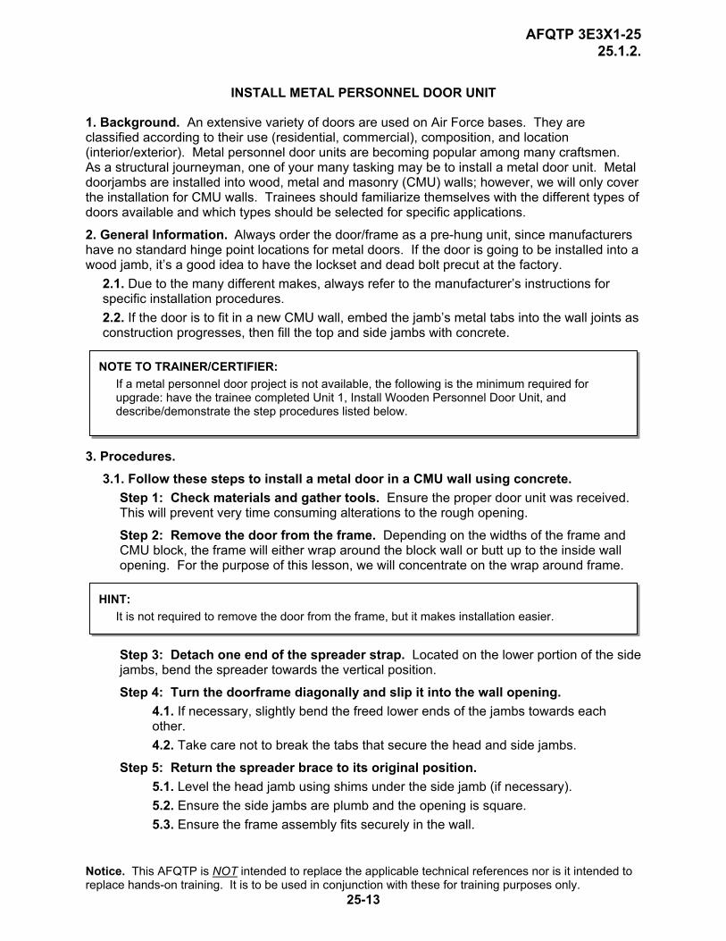
1. Background. An extensive variety of doors are used on Air Force bases. They are classified according to their use (residential, commercial), composition, and location (interior/exterior). Metal personnel door units are becoming popular among many craftsmen. As a structural journeyman, one of your many tasking may be to install a metal door unit. Metal doorjambs are installed into wood, metal and masonry (CMU) walls; however, we will only cover the installation for CMU walls. Trainees should familiarize themselves with the different types of doors available and which types should be selected for specific applications.
2. General Information. Always order the door/frame as a pre-hung unit, since manufacturers have no standard hinge point locations for metal doors. If the door is going to be installed into a wood jamb, it’s a good idea to have the lockset and dead bolt precut at the factory.
2.1. Due to the many different makes, always refer to the manufacturer’s instructions for specific installation procedures. 2.2. If the door is to fit in a new CMU wall, embed the jamb’s metal tabs into the wall joints as construction progresses, then fill the top and side jambs with concrete.
NOTE TO TRAINER/CERTIFIER: If a metal personnel door project is not available, the following is the minimum required for upgrade: have the trainee completed Unit 1, Install Wooden Personnel Door Unit, and describe/demonstrate the step procedures listed below.
3. Procedures. 3.1. Follow these steps to install a metal door in a CMU wall using concrete.
Step 1: Check materials and gather tools. Ensure the proper door unit was received. This will prevent very time consuming alterations to the rough opening. Step 2: Remove the door from the frame. Depending on the widths of the frame and CMU block, the frame will either wrap around the block wall or butt up to the inside wall opening. For the purpose of this lesson, we will concentrate on the wrap around frame.
HINT: It is not required to remove the door from the frame, but it makes installation easier.
Step 3: Detach one end of the spreader strap. Located on the lower portion of the side jambs, bend the spreader towards the vertical position.
Step 4: Turn the doorframe diagonally and slip it into the wall opening. 4.1. If necessary, slightly bend the freed lower ends of the jambs towards each other. 4.2. Take care not to break the tabs that secure the head and side jambs.
Step 5: Return the spreader brace to its original position. 5.1. Level the head jamb using shims under the side jamb (if necessary). 5.2. Ensure the side jambs are plumb and the opening is square. 5.3. Ensure the frame assembly fits securely in the wall.
Notice. This AFQTP is NOT intended to replace the applicable technical references nor is it intended to replace hands-on training. It is to be used in conjunction with these for training purposes only.
25-13
AFQTP 3E3X1-25 25.1.2.
5.4. If it does not, secure it and make sure concrete cannot leak out when the frame is filled with concrete.
SAFETY: PERSONAL PROTECTIVE EQUIPMENT MUST BE WORN WHEN DRILLING, HAMMERING, OR CUTTING MASONRY MATERIALS. USE LEATHER GLOVES WHEN MIXING OR WORKING WITH WET CEMENT OR CONCRETE. FAILURE TO DO SO CAN RESULT IN SKIN BURNS.
Step 6: Carefully punch three holes in the blocks directly above the header jamb. 6.1. Place one in the center and one on either side above the side jambs. 6.2. The holes should be just large enough to pour concrete into the voids between the block and the jambs. 6.3. Avoid large holes, as you will have to repair them later.
Step 7: Fill CMU with concrete. 7.1. Recheck level/plumb, and then fill the jambs with concrete. 7.2. Tamp the jambs carefully with a hammer and wood block to consolidate the concrete. 7.3. Be sure the voids are filled thoroughly. 7.4. After the concrete has set up, fill in the holes above the header jamb with a rich mixture of Portland cement, sand, and lime.
Step 8: Allow the concrete to set about 48 hours. 8.1. Remove the spreader from the base of the frame. 8.2. Reinstall the door and do an operational check.
3.2. Follow these steps to install a metal door in a CMU wall using anchor bolts.
Step 1: Check materials and gather tools. Ensure the proper door unit was received. This will prevent very time consuming alterations to the rough opening. Step 2: Place the frame into the opening and secure with shims. Use the skills learned in Unit 1 to plumb and level the jamb.
Step 3: Install anchor bolts. Drill holes into the frame and CMU for the anchor bolts. Install the bolts, but do not tighten.
Step 4: Tighten the bolts. Add more shims between the jamb and CMU wall. Ensure the jamb is still plumb/level. Fully tighten the bolts
Step 5: Grind the bolt heads flush with the surface. Step 6: Apply a patching compound creating a smooth surface.
NOTE: The steps referenced above are two ways to install some metal personnel door units. There are many different manufacturers and many different installation methods. Always refer to the manufacturer’s instructions of your particular unit.
Notice. This AFQTP is NOT intended to replace the applicable technical references nor is it intended to replace hands-on training. It is to be used in conjunction with these for training purposes only.
25-14
AFQTP 3E3X1-25 25.1.2.
REVIEW QUESTIONS FOR
INSTALL METAL PERSONNEL DOOR UNIT
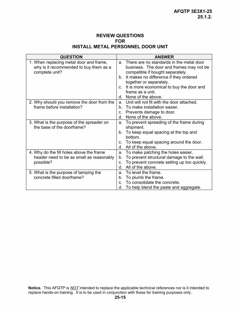
QUESTION ANSWER 1. When replacing metal door and frame,
why is it recommended to buy them as a complete unit?
a. There are no standards in the metal door business. The door and frames may not be compatible if bought separately.
b. It makes no difference if they ordered together or separately.
c. It is more economical to buy the door and frame as a unit.
d. None of the above. 2. Why should you remove the door from the
frame before installation? a. Unit will not fit with the door attached. b. To make installation easier. c. Prevents damage to door. d. None of the above.
3. What is the purpose of the spreader on the base of the doorframe?
a. To prevent spreading of the frame during shipment.
b. To keep equal spacing at the top and bottom.
c. To keep equal spacing around the door. d. All of the above.
4. Why do the fill holes above the frame header need to be as small as reasonably possible?
a. To make patching the holes easier. b. To prevent structural damage to the wall. c. To prevent concrete setting up too quickly. d. All of the above.
5. What is the purpose of tamping the concrete filled doorframe?
a. To level the frame. b. To plumb the frame. c. To consolidate the concrete. d. To help blend the paste and aggregate.
Notice. This AFQTP is NOT intended to replace the applicable technical references nor is it intended to replace hands-on training. It is to be used in conjunction with these for training purposes only.
25-15

AFQTP 3E3X1-25 25.1.2.
INSTALL METAL PERSONNEL DOOR UNIT PERFORMANCE CHECKLIST INSTRUCTIONS:
The trainee must satisfactorily perform all parts of the task without assistance. Evaluate the trainee’s performance using this checklist.
DID THE TRAINEE…. YES NO 1. check materials prior to arrival on job site and brought all required tools? 2. remove the door from the frame? 3. free one end of the temporary spreader? 4. insert the unit in the opening without breaking the tabs? 5. return the spreader to the original position? 6. punch the holes just large enough to fill the frame with concrete? 7. recheck the head jamb for level before pouring, and tamping the frame as
the concrete was being poured?
8. repair the fill holes properly? 9. allow the concrete to cure about 48 hours, the spreader removed, and the
door re-hung, and an operational check performed?
10. install the threshold, if applicable? 11. comply with all safety requirements? FEEDBACK: Trainer/Certifier should provide both positive and/or negative feedback to the trainee immediately after the task is performed. This will ensure the issue is still fresh in the mind of both the trainee and trainer/certifier.
Notice. This AFQTP is NOT intended to replace the applicable technical references nor is it intended to replace hands-on training. It is to be used in conjunction with these for training purposes only.
25-16
AFQTP 3E3X1-25 25.2.1.
REPAIR PERSONNEL DOOR UNITS
MODULE 25 AFQTP UNIT 2
WOOD (25.2.1.)
Notice. This AFQTP is NOT intended to replace the applicable technical references nor is it intended to replace hands-on training. It is to be used in conjunction with these for training purposes only.
25-17
AFQTP 3E3X1-25 25.2.1.
REPAIR WOOD PERSONNEL DOOR UNITS
Task Training Guide
STS Reference Number/Title:
25.2.1. – Repair wood personnel door units.
Training References:
1. Career Development Course (CDC) Structural Journeyman 3E351C, Volume 1, Unit 5, Section 5-2, Lesson 042; Inspecting and Maintaining Interior Doors.
2. Door manufacturer’s instructions.
Prerequisites: 1. Possess as a minimum a 3E331 AFSC. 2. Review the following references:
2.1. CDC Structural Journeyman 3E351C, Volume 1, Unit 5, Section 5-2, Lesson 042. 2.2. Door manufacturer’s instructions.
Equipment/Tools Required:
1. General 3E3X1 tool kit. 2. Personal safety equipment. 3. Portable electric drill. 4. Extension cord. 5. Wood clamps. 6. Shims (cardboard or sheet metal). 7. Dowel pins. 8. Wood Glue. 9. 6-foot stepladder.
10. Small brush for applying glue. 11. Replacement hinges. 12. Wood screws. 13. Wood door unit.
Learning Objective:
Trainee should be able to describe the different methods of wood door unit repair, pass written test and perform a minimum of 1 repair for qualification.
Samples of Behavior:
1. Trainee will be able to successfully and safely repair a wood personnel door unit.
2. Trainee will be able to inspect and adjust the operation of a wood personnel door unit.
Notes: Any safety violation is an automatic failure.
Notice. This AFQTP is NOT intended to replace the applicable technical references nor is it intended to replace hands-on training. It is to be used in conjunction with these for training purposes only.
25-18

AFQTP 3E3X1-25 25.2.1.
REPAIR WOOD PERSONNEL DOOR UNITS
1. Background. Many things can happen to keep doors from operating properly. Decay or shrinkage of door members from exposure to the weather or to severe temperature changes can cause door distortion or failure. Loose door joints, sagging lock stiles, or loose or damaged hinges will make a door drag or bind. Doorjambs often split around hinge and lock locations causing security problems. As a structural journeyman, you will not only be responsible for identifying the problem, but you have to know how to fix it—correctly. In this unit, we will discuss the common defects and repair methods of each.
NOTE TO TRAINER/CERTIFIER: Due to the possibility of encountering more than one of the following problems, only one type of repair needs to be accomplished for upgrade. Have the trainee complete the written test.
2. Procedures. Follow these steps to repair wood doors and jambs.
SAFETY: DUE TO THE SIZE AND WEIGHT OF A DOOR UNIT, TRAINEE MAY NEED ASSISTANCE IF THE REPAIR REQUIRES THE DOOR TO BE REMOVED FROM THE JAMB.
2.1. Shrunk Door. The door has shrunk and no longer makes proper contact with the stop or fails to lock properly.
Step 1: Gather the required tools, materials, and safety equipment. Step 2: Remove the hinge leaves. Install cardboard or metal shims underneath the hinge leaves.
Step 3: Remove the striker plate. If the hinge shims do not provide enough filler, it may be necessary to shim beneath the striker plate in the same manner.
Step 4: Reinstall the hinge leaves and striker plate. Longer screws may be required.
Step 5: Check operation and make final adjustments if needed.
2.2. Warped Door. A warped door may be bowed inward or outward at the hinge edge causing it to bind against the stop. This problem is most prevalent on interior doors, where only two hinges were installed. A door may also develop a twist, making it impossible to close without applying pressure against bulging areas.
Step 1: Gather required tools, materials, and safety equipment. Step 2: If door is bowed inward or outward.
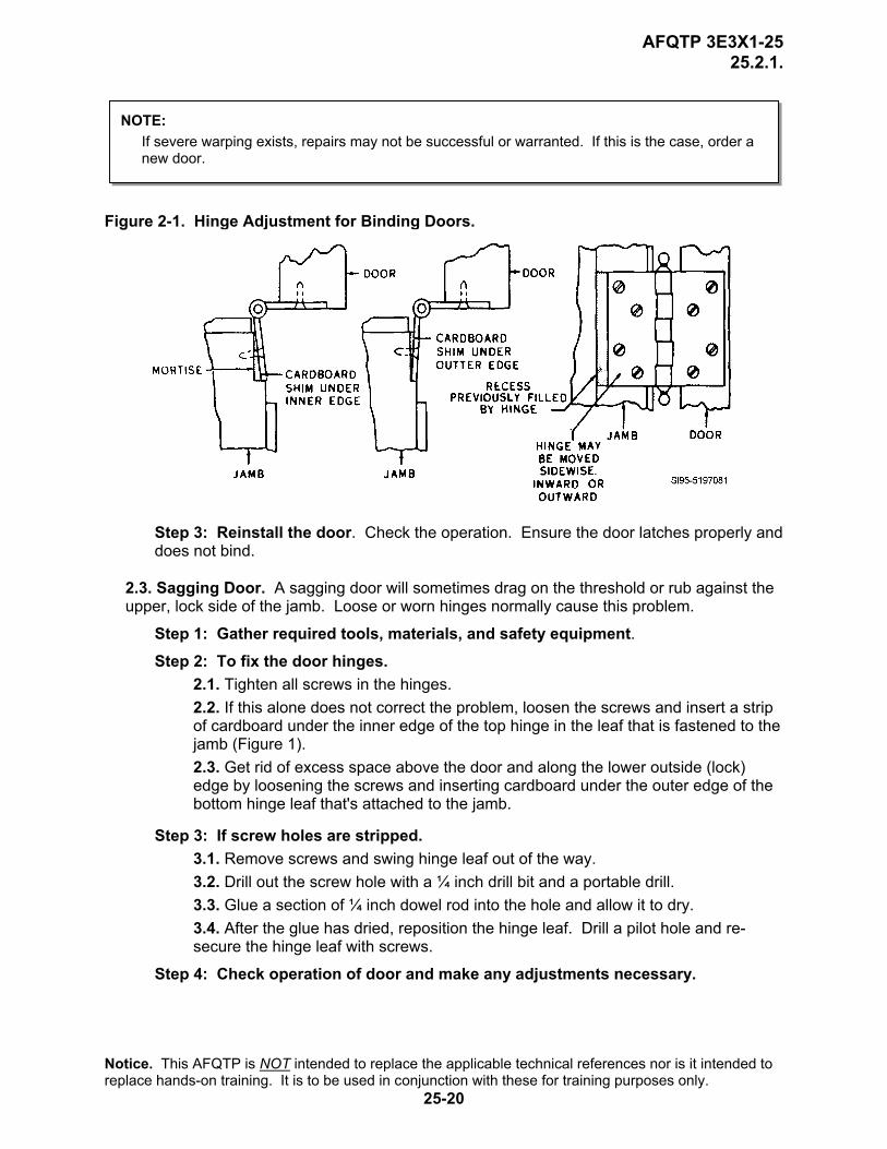
2.1. Eliminate this problem by placing another hinge midway between the first two. 2.2. If another hinge isn’t available, make temporary repairs by shifting the hinges outward on the doorjamb (Figure 2-1). 2.3. If the door has become twisted, remove it, and lay it on a flat surface, and clamp or weigh it down. 2.4. If the door is still warped after a reasonable length of time, battens screwed to the door will help restore it to a true plane. 2.5. The jamb stops may be moved to help correct this problem.
Notice. This AFQTP is NOT intended to replace the applicable technical references nor is it intended to replace hands-on training. It is to be used in conjunction with these for training purposes only.
25-19
AFQTP 3E3X1-25 25.2.1.
NOTE: If severe warping exists, repairs may not be successful or warranted. If this is the case, order a new door.
Figure 2-1. Hinge Adjustment for Binding Doors.
Step 3: Reinstall the door. Check the operation. Ensure the door latches properly and does not bind.
2.3. Sagging Door. A sagging door will sometimes drag on the threshold or rub against the upper, lock side of the jamb. Loose or worn hinges normally cause this problem.
Step 1: Gather required tools, materials, and safety equipment. Step 2: To fix the door hinges.
2.1. Tighten all screws in the hinges. 2.2. If this alone does not correct the problem, loosen the screws and insert a strip of cardboard under the inner edge of the top hinge in the leaf that is fastened to the jamb (Figure 1). 2.3. Get rid of excess space above the door and along the lower outside (lock) edge by loosening the screws and inserting cardboard under the outer edge of the bottom hinge leaf that's attached to the jamb.
Step 3: If screw holes are stripped. 3.1. Remove screws and swing hinge leaf out of the way. 3.2. Drill out the screw hole with a ¼ inch drill bit and a portable drill. 3.3. Glue a section of ¼ inch dowel rod into the hole and allow it to dry. 3.4. After the glue has dried, reposition the hinge leaf. Drill a pilot hole and re-secure the hinge leaf with screws.
Step 4: Check operation of door and make any adjustments necessary.
Notice. This AFQTP is NOT intended to replace the applicable technical references nor is it intended to replace hands-on training. It is to be used in conjunction with these for training purposes only.
25-20
AFQTP 3E3X1-25 25.2.1.
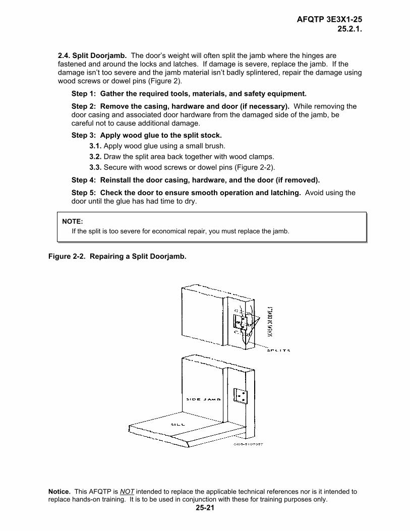
2.4. Split Doorjamb. The door’s weight will often split the jamb where the hinges are fastened and around the locks and latches. If damage is severe, replace the jamb. If the damage isn’t too severe and the jamb material isn’t badly splintered, repair the damage using wood screws or dowel pins (Figure 2).
Step 1: Gather the required tools, materials, and safety equipment. Step 2: Remove the casing, hardware and door (if necessary). While removing the door casing and associated door hardware from the damaged side of the jamb, be careful not to cause additional damage. Step 3: Apply wood glue to the split stock.
3.1. Apply wood glue using a small brush. 3.2. Draw the split area back together with wood clamps. 3.3. Secure with wood screws or dowel pins (Figure 2-2).
Step 4: Reinstall the door casing, hardware, and the door (if removed). Step 5: Check the door to ensure smooth operation and latching. Avoid using the door until the glue has had time to dry.
NOTE: If the split is too severe for economical repair, you must replace the jamb.
Figure 2-2. Repairing a Split Doorjamb.
Notice. This AFQTP is NOT intended to replace the applicable technical references nor is it intended to replace hands-on training. It is to be used in conjunction with these for training purposes only.
25-21
AFQTP 3E3X1-25 25.2.1.
REVIEW QUESTIONS FOR
REPAIR WOOD PERSONNEL DOOR UNITS
QUESTION ANSWER 1. If a door has shrunk, you should? a. Install larger hinges.
b. Remove door, place on flat surface, and weigh down.
c. Install shims of cardboard or metal underneath hinge leafs.
d. All of the above. 2. Why should you place another hinge midway
on as interior door? a. Door is twisted. b. Doorjamb is split. c. Door has shrunk. d. Door has bowed.
3. The stop may be moved to correct a bowed or twisted door?
a. True. b. False.
4. A sagging door is normally caused by_________.
a. a split doorjamb. b. a raised threshold. c. a broken door stile. d. loose or worn hinges.
5. For a sagging door, you should insert a strip of cardboard under the ________.
a. inner edge of the top hinge in the leaf that is fastened to the jamb.
b. inner edge of the bottom hinge in the leaf that is fastened to the jamb.
c. outer edge of the top hinge in the leaf that is fastened to the jamb.
d. outer edge of the bottom hinge in the leaf that is fastened to the jamb.
6. Excess space above the door and along the lower outside (lock) edge is best eliminated by inserting cardboard under the _______.
a. inner edge of the top hinge in the leaf that is fastened to the jamb.
b. inner edge of the bottom hinge in the leaf that is fastened to the jamb.
c. outer edge of the top hinge in the leaf that is fastened to the jamb.
d. outer edge of the bottom hinge in the leaf that is fastened to the jamb.
7. If screw holes are stripped in a wood door, remove hinge leaf, drill out hole and ____________.
a. fill with wood putty. b. pour epoxy in hole. c. glue a dowel in place. d. use manufactured inserts to fill hole.
8. Before repairing a split doorjamb, you must remove the___________.
a. casing and associated hardware. b. rough header. c. threshold. d. all of the above.
9. When repairing a split doorjamb, what should you apply wood glue with?
a. Putty knife. b. Small brush. c. Cotton swab. d. Caulking gun.
10. After gluing a split doorjamb, draw the area back together using_________.
a. C-Clamps. b. Wood clamps. c. Carriage bolts. d. Tie down straps.
Notice. This AFQTP is NOT intended to replace the applicable technical references nor is it intended to replace hands-on training. It is to be used in conjunction with these for training purposes only.
25-22

AFQTP 3E3X1-25 25.2.1.
REPAIR WOOD PERSONNEL DOOR UNITS PERFORMANCE CHECKLIST INSTRUCTIONS:
The trainee must satisfactorily perform all parts of the task without assistance. Evaluate the trainee’s performance using this checklist.
DID THE TRAINEE…. YES NO 1. have the required tools and equipment? 2. correctly assess the problem? 3. correctly fix unit with shrunken door? 4. correctly repair a warped door which was bowed on the hinge side? 5. correctly repair a warped door with a twist in it? 6. repair a sagging door correctly? 7. correctly repair a split doorjamb? 8. comply with all safety requirements? FEEDBACK: Trainer/Certifier should provide both positive and/or negative feedback to the trainee immediately after the task is performed. This will ensure the issue is still fresh in the mind of both the trainee and trainer/certifier.
Notice. This AFQTP is NOT intended to replace the applicable technical references nor is it intended to replace hands-on training. It is to be used in conjunction with these for training purposes only.
25-23

AFQTP 3E3X1-25 25.2.2.
REPAIR PERSONNEL DOOR UNITS
MODULE 25 AFQTP UNIT 2
METAL (25.2.2.)
Notice. This AFQTP is NOT intended to replace the applicable technical references nor is it intended to replace hands-on training. It is to be used in conjunction with these for training purposes only.
25-24

AFQTP 3E3X1-25 25.2.2.
REPAIR METAL PERSONNEL DOOR UNITS
Task Training Guide
STS Reference Number/Title:
25.2.2. – Repair metal personnel door unit.
Training References:
1. Career Development Course (CDC) Structural Journeyman 3E351C, Volume 1, Unit 5, Section 5-2, Lesson 042; Inspecting and Maintaining Interior Doors.
2. Door manufacturer’s instructions.
Prerequisites: 1. Possess as a minimum a 3E331 AFSC. 2. Review the following references:
2.1. CDC Structural Journeyman 3E351C, Volume 1, Unit 5, Section 5-2, Lesson 042. 2.2. Door manufacturer’s instructions.
Equipment/Tools Required:
1. General 3E3X1 tool kit. 2. Personal safety equipment. 3. Shop made hinge alignment tool. 4. Cardboard shims. 5. Hand grinder. 6. Metal door unit.
Learning Objective:
Trainee should be able to identify the causes and proper repair methods for repairing metal door units.
Samples of Behavior:
1. Trainee will be able to successfully and safely repair a metal personnel door unit.
2. Trainee will be able to inspect and adjust the operation of a metal personnel door unit.
Notes: Any safety violation is an automatic failure.
Notice. This AFQTP is NOT intended to replace the applicable technical references nor is it intended to replace hands-on training. It is to be used in conjunction with these for training purposes only.
25-25
AFQTP 3E3X1-25 25.2.2.
REPAIR METAL PERSONNEL DOOR UNITS
1. Background. As you learned in the previous unit, there are many different types of metal personnel door units throughout the Air Force. When installed properly, metal personnel door units require very little maintenance. However, most doors will inevitably require repair sooner or later. It is important for you, as a structural journeyman, to be able to recognize the problem and to know how to fix it. As we mentioned in previous units, the building’s security is at stake.
2. Common Defects and Repair Methods. Before you make any door repairs, first determine what caused the damage. Usually by visually checking the door alignment and operation you can find the problem.
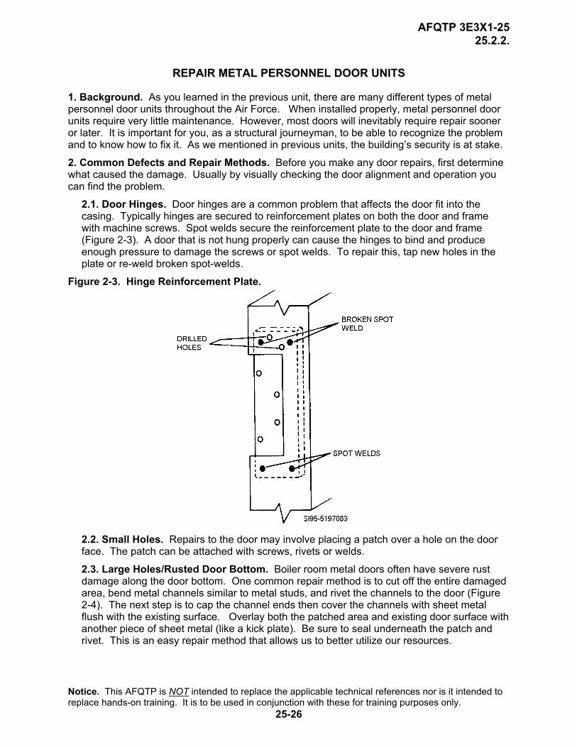
2.1. Door Hinges. Door hinges are a common problem that affects the door fit into the casing. Typically hinges are secured to reinforcement plates on both the door and frame with machine screws. Spot welds secure the reinforcement plate to the door and frame (Figure 2-3). A door that is not hung properly can cause the hinges to bind and produce enough pressure to damage the screws or spot welds. To repair this, tap new holes in the plate or re-weld broken spot-welds.
Figure 2-3. Hinge Reinforcement Plate.
2.2. Small Holes. Repairs to the door may involve placing a patch over a hole on the door face. The patch can be attached with screws, rivets or welds.
2.3. Large Holes/Rusted Door Bottom. Boiler room metal doors often have severe rust damage along the door bottom. One common repair method is to cut off the entire damaged area, bend metal channels similar to metal studs, and rivet the channels to the door (Figure 2-4). The next step is to cap the channel ends then cover the channels with sheet metal flush with the existing surface. Overlay both the patched area and existing door surface with another piece of sheet metal (like a kick plate). Be sure to seal underneath the patch and rivet. This is an easy repair method that allows us to better utilize our resources.
Notice. This AFQTP is NOT intended to replace the applicable technical references nor is it intended to replace hands-on training. It is to be used in conjunction with these for training purposes only.
25-26

AFQTP 3E3X1-25 25.2.2.
Figure 2-4. Door Bottom Repair.
SAFETY: IF A METAL PERSONNEL DOOR HAS TO BE REMOVED IN ORDER TO MAKE REPAIRS, TRAINEE WILL NEED AN ASSISTANT.
NOTE TO TRAINER/CERTIFIER: If a metal personnel door unit repair project is not available, the minimum required for upgrade is to have the trainee demonstrate the repair steps listed below.
3. Procedures. Follow these steps to repair metal personnel door units: Step 1: Gather required equipment. Having the proper equipment will save time by preventing you from having to go back to the shop and retrieve additional tools.
Step 2: Determine cause of damage. Visually check door alignment and operation. If the door fits tight or rubs at one end, a hinge could be bent or sprung. If this is the case, replace the hinge.
Step 3: Check hinges for binding. If the door tends to spring open or is hard to close, the hinges could be bound or the reinforcement plates may be misaligned. In this situation insert cardboard shims under the outer edges on the frame side hinges (Figure 2-5).
Figure 2-5. Hinge Adjustment for Binding Door.
Step 4: Check for twisted hinge plate. If a hinge plate is twisted, you may be able to use a shop made tool, (Figure 2-6 on the next page) to straighten it. Attach the tool to the reinforcement plate with hinge screws and pry the plate back to its correct position.
NOTE: Be careful not to pull the reinforcement plate out of the doorjamb.
Notice. This AFQTP is NOT intended to replace the applicable technical references nor is it intended to replace hands-on training. It is to be used in conjunction with these for training purposes only.
25-27
AFQTP 3E3X1-25 25.2.2.
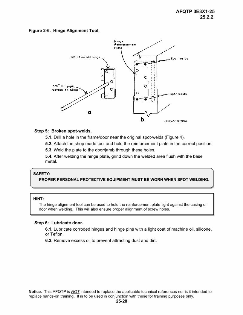
Figure 2-6. Hinge Alignment Tool.
Step 5: Broken spot-welds. 5.1. Drill a hole in the frame/door near the original spot-welds (Figure 4). 5.2. Attach the shop made tool and hold the reinforcement plate in the correct position. 5.3. Weld the plate to the door/jamb through these holes. 5.4. After welding the hinge plate, grind down the welded area flush with the base metal.
SAFETY: PROPER PERSONAL PROTECTIVE EQUIPMENT MUST BE WORN WHEN SPOT WELDING.
HINT: The hinge alignment tool can be used to hold the reinforcement plate tight against the casing or door when welding. This will also ensure proper alignment of screw holes.
Step 6: Lubricate door. 6.1. Lubricate corroded hinges and hinge pins with a light coat of machine oil, silicone, or Teflon. 6.2. Remove excess oil to prevent attracting dust and dirt.
Notice. This AFQTP is NOT intended to replace the applicable technical references nor is it intended to replace hands-on training. It is to be used in conjunction with these for training purposes only.
25-28
AFQTP 3E3X1-25 25.2.2.
REVIEW QUESTIONS FOR
REPAIR METAL PERSONNEL DOOR UNITS
QUESTION ANSWER 1. How are hinge reinforcement plates
attached to the door and frame? a. Bead Welds. b. Spot Welds. c. Screws. d. Rivets.
2. If the door fits tight or rubs at one end, a hinge is probably ________.
a. loose. b. twisted. c. binding. d. sprung.
3. A door that springs open is usually a sign of a binding hinge.
a. True. b. False.
4. What procedure is used to adjust a binding hinge or a misaligned reinforcement plate?
a. Re-weld reinforcement plates to the frame.
b. Use an alignment tool to adjust the hinge plate.
c. Shim the outer edge of the hinge on the frame side.
d. Oil the hinge and hinge pin. 5. What is the shop made hinge tool used for? a. To straighten twisted hinge plates
b. To straighten bent door frames. c. To remove twisted hinge plates. d. To remove striped screws.
6. Holes are drilled in the frame and door near the hinge placement to ________.
a. align screw holes. b. align the door in the doorframe. c. reweld the reinforcement plate to the
frame or door. d. reweld the door frame to the mounting
brackets.
Notice. This AFQTP is NOT intended to replace the applicable technical references nor is it intended to replace hands-on training. It is to be used in conjunction with these for training purposes only.
25-29
AFQTP 3E3X1-25 25.2.2.
REPAIR METAL PERSONNEL DOOR UNITS PERFORMANCE CHECKLIST INSTRUCTIONS:
The trainee must satisfactorily perform all parts of the task without assistance. Evaluate the trainee’s performance using this checklist.
DID THE TRAINEE…. YES NO 1. gather the required tools and materials? 2. determine what caused the damage? 3. check the hinges for binding? 4. check for twisted hinge plates? 5. properly re-weld broken spot welds, if required? 6. properly lubricate the hinges and hinge pins? 7. comply with all safety requirements? FEEDBACK: Trainer/Certifier should provide both positive and/or negative feedback to the trainee immediately after the task is performed. This will ensure the issue is still fresh in the mind of both the trainee and trainer/certifier.
Notice. This AFQTP is NOT intended to replace the applicable technical references nor is it intended to replace hands-on training. It is to be used in conjunction with these for training purposes only.
25-30
AFQTP 3E3X1-25 25.5.1.
PERSONNEL DOOR HARDWARE
MODULE 25 AFQTP UNIT 5
INSTALL DOOR CLOSERS (25.5.1.)
Notice. This AFQTP is NOT intended to replace the applicable technical references nor is it intended to replace hands-on training. It is to be used in conjunction with these for training purposes only.
25-31
AFQTP 3E3X1-25 25.5.1.
INSTALL DOOR CLOSERS
Task Training Guide
STS Reference Number/Title:
25.5.1. - Install door closers.
Training References:
1. Career Development Course (CDC) Structural Journeyman 3E351C, Volume 1, Unit 5, Section 5-2, Lesson 042; Inspecting and Maintaining Interior Doors.
2. Door closer manufacturer’s instructions.
Prerequisites: 1. Possess as a minimum a 3E331 AFSC. 2. Review the following references:
2.1. CDC Structural Journeyman 3E351C, Volume 1, Unit 5, Section 5-2, Lesson 042. 2.2. Door closer manufacturer’s instructions.
Equipment/Tools Required:
1. General 3E3X1 tool kit. 2. Personal safety equipment. 3. 6-foot stepladder. 4. 3/8-inch portable drill. 5. Extension cord. 6. Tap and die set. 7. Tape. 8. Door closer.
Learning Objective:
Trainee should be able to identify the different types of door closers and the procedures for installing them.
Samples of Behavior:
1. Trainee should be able to successfully and safely install door closers.
2. Trainee should be able to inspect and adjust the operation of a door closer.
Notes: Any safety violation is an automatic failure.
Notice. This AFQTP is NOT intended to replace the applicable technical references nor is it intended to replace hands-on training. It is to be used in conjunction with these for training purposes only.
25-32
AFQTP 3E3X1-25 25.5.1.
INSTALL DOOR CLOSERS
1. Background. As you learned in the last unit, door hinges are oftentimes damaged from excessive force from wind and people. For this reason, many doors have door closers installed on them. Door closers serve dual purposes—close the door and keep the door from opening too far. As a structural journeyman, you may have to install, maintain, adjust, or repair a closer at some point in your Air Force career. Obviously, most of the information will be from the manufacturer’s instructions, but you need to be familiar with a few general door closer principles. Many emergency standby calls are a result of jammed door closers. The more you know, the less troublesome those calls may be.
2. Door Closer Types. There are two basic door closer types—pneumatic and hydraulic.
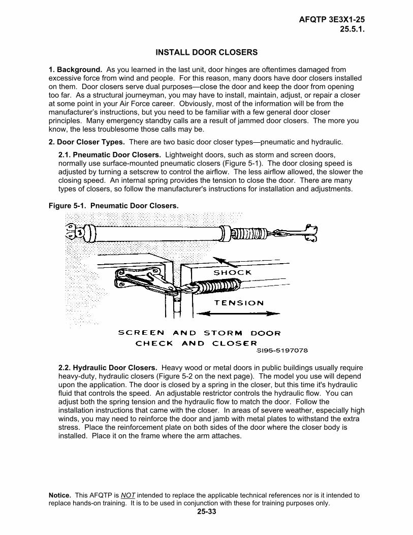
2.1. Pneumatic Door Closers. Lightweight doors, such as storm and screen doors, normally use surface-mounted pneumatic closers (Figure 5-1). The door closing speed is adjusted by turning a setscrew to control the airflow. The less airflow allowed, the slower the closing speed. An internal spring provides the tension to close the door. There are many types of closers, so follow the manufacturer's instructions for installation and adjustments.
Figure 5-1. Pneumatic Door Closers.
2.2. Hydraulic Door Closers. Heavy wood or metal doors in public buildings usually require heavy-duty, hydraulic closers (Figure 5-2 on the next page). The model you use will depend upon the application. The door is closed by a spring in the closer, but this time it's hydraulic fluid that controls the speed. An adjustable restrictor controls the hydraulic flow. You can adjust both the spring tension and the hydraulic flow to match the door. Follow the installation instructions that came with the closer. In areas of severe weather, especially high winds, you may need to reinforce the door and jamb with metal plates to withstand the extra stress. Place the reinforcement plate on both sides of the door where the closer body is installed. Place it on the frame where the arm attaches.
Notice. This AFQTP is NOT intended to replace the applicable technical references nor is it intended to replace hands-on training. It is to be used in conjunction with these for training purposes only.
25-33

AFQTP 3E3X1-25 25.5.1.
Figure 5-2. Typical Hydraulic Closers. 3. Procedures. Follow these steps to install a door closer:
Step 1: Gather required tools and materials. Having the proper equipment will save time preventing you from having to go back to the shop and retrieve additional tools. Some tools you will need are a general toolbox, 4-foot stepladder, battery or electric drill, and extension cord.
Step 2: Determine what closer type is needed. When choosing what type of door closer you are going to install, remember that pneumatic closers are commonly used on lightweight doors, and hydraulic closers are used on heavier doors.
Step 3: Determine door swing. Some hydraulic door closers have a specific swing, while others can be changed at the time of installation. Regardless of the type used, the door swing must be known in advance. Four door swing types are shown in Figure 5-3. Always face the outside of the door to determine its swing (or hand). The outside is the street side of an entrance door or the corridor side of a room door.
Figure 5-3. Door Swing.
NOTE TO TRAINER/CERTIFIER: If a job order is not available to complete this task, have the trainee complete Steps 1 – 4 on any available door, demonstrate Steps 5 and 6, complete Step 7 on any available door closer.
Notice. This AFQTP is NOT intended to replace the applicable technical references nor is it intended to replace hands-on training. It is to be used in conjunction with these for training purposes only.
25-34
AFQTP 3E3X1-25 25.5.1.
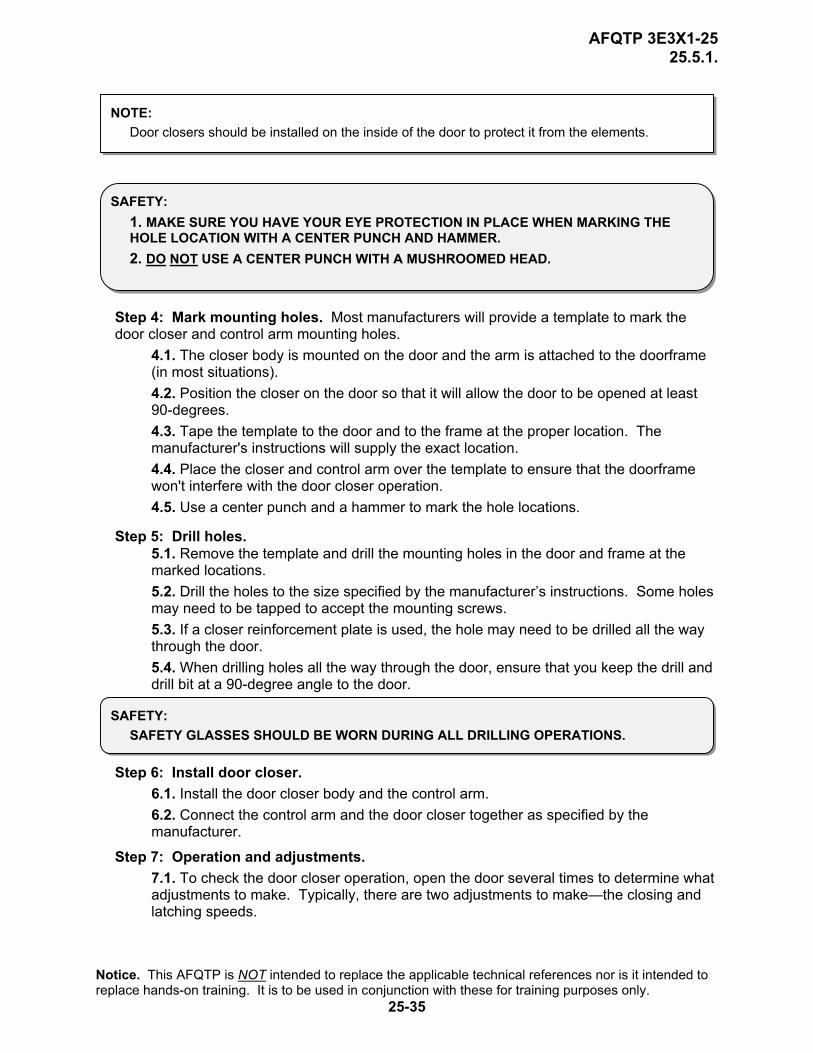
NOTE: Door closers should be installed on the inside of the door to protect it from the elements.
SAFETY: 1. MAKE SURE YOU HAVE YOUR EYE PROTECTION IN PLACE WHEN MARKING THE HOLE LOCATION WITH A CENTER PUNCH AND HAMMER. 2. DO NOT USE A CENTER PUNCH WITH A MUSHROOMED HEAD.
Step 4: Mark mounting holes. Most manufacturers will provide a template to mark the door closer and control arm mounting holes.
4.1. The closer body is mounted on the door and the arm is attached to the doorframe (in most situations). 4.2. Position the closer on the door so that it will allow the door to be opened at least 90-degrees. 4.3. Tape the template to the door and to the frame at the proper location. The manufacturer's instructions will supply the exact location. 4.4. Place the closer and control arm over the template to ensure that the doorframe won't interfere with the door closer operation. 4.5. Use a center punch and a hammer to mark the hole locations.
Step 5: Drill holes. 5.1. Remove the template and drill the mounting holes in the door and frame at the marked locations. 5.2. Drill the holes to the size specified by the manufacturer’s instructions. Some holes may need to be tapped to accept the mounting screws. 5.3. If a closer reinforcement plate is used, the hole may need to be drilled all the way through the door. 5.4. When drilling holes all the way through the door, ensure that you keep the drill and drill bit at a 90-degree angle to the door.
SAFETY: SAFETY GLASSES SHOULD BE WORN DURING ALL DRILLING OPERATIONS.
Step 6: Install door closer. 6.1. Install the door closer body and the control arm. 6.2. Connect the control arm and the door closer together as specified by the manufacturer.
Step 7: Operation and adjustments. 7.1. To check the door closer operation, open the door several times to determine what adjustments to make. Typically, there are two adjustments to make—the closing and latching speeds.
Notice. This AFQTP is NOT intended to replace the applicable technical references nor is it intended to replace hands-on training. It is to be used in conjunction with these for training purposes only.
25-35

AFQTP 3E3X1-25 25.5.1.
7.1.1. The closing speed controls the rate at which the door will close up to the latching point. 7.1.2. The latching adjustment varies the speed the locking device will latch onto the striker plate.
7.2. Make adjustments using the adjusting screws on the closer body.
Step 8: Clean up the area.
Notice. This AFQTP is NOT intended to replace the applicable technical references nor is it intended to replace hands-on training. It is to be used in conjunction with these for training purposes only.
25-36
AFQTP 3E3X1-25 25.5.1.
REVIEW QUESTIONS
FOR INSTALL DOOR CLOSERS
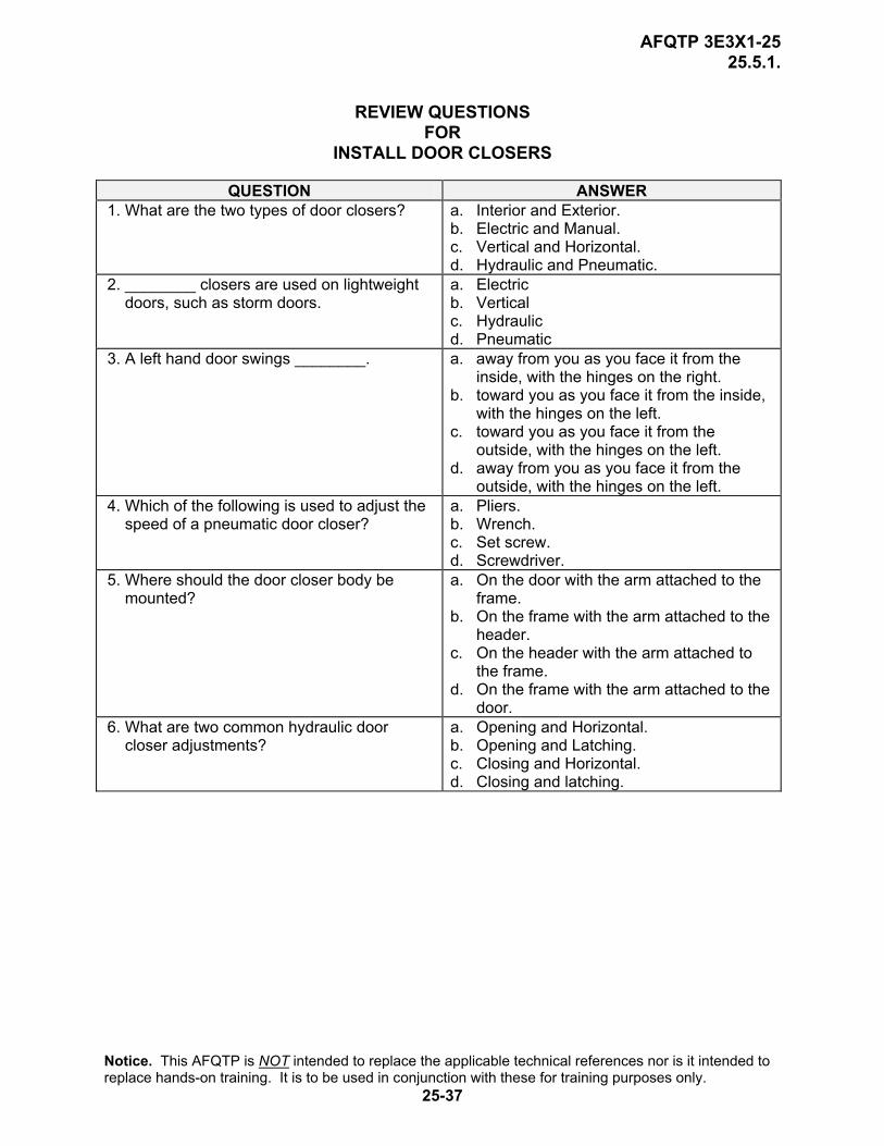
QUESTION ANSWER 1. What are the two types of door closers? a. Interior and Exterior.
b. Electric and Manual. c. Vertical and Horizontal. d. Hydraulic and Pneumatic.
2. ________ closers are used on lightweight doors, such as storm doors.
a. Electric b. Vertical c. Hydraulic d. Pneumatic
3. A left hand door swings ________. a. away from you as you face it from the inside, with the hinges on the right.
b. toward you as you face it from the inside, with the hinges on the left.
c. toward you as you face it from the outside, with the hinges on the left.
d. away from you as you face it from the outside, with the hinges on the left.
4. Which of the following is used to adjust the speed of a pneumatic door closer?
a. Pliers. b. Wrench. c. Set screw. d. Screwdriver.
5. Where should the door closer body be mounted?
a. On the door with the arm attached to the frame.
b. On the frame with the arm attached to the header.
c. On the header with the arm attached to the frame.
d. On the frame with the arm attached to the door.
6. What are two common hydraulic door closer adjustments?
a. Opening and Horizontal. b. Opening and Latching. c. Closing and Horizontal. d. Closing and latching.
Notice. This AFQTP is NOT intended to replace the applicable technical references nor is it intended to replace hands-on training. It is to be used in conjunction with these for training purposes only.
25-37
AFQTP 3E3X1-25 25.5.1.
INSTALL DOOR CLOSERS PERFORMANCE CHECKLIST INSTRUCTIONS:
The trainee must satisfactorily perform all parts of the task without assistance. Evaluate the trainee’s performance using this checklist.
DID THE TRAINEE…. YES NO 1. have the required tools and equipment? 2. determine the correct type of closer to be used? 3. determine the correct door swing? 4. use the template to mark the mounting holes? 5. drill the holes properly? 6. install the door closer properly? 7. adjust the door closer properly? 8. comply with all safety requirements? FEEDBACK: Trainer/Certifier should provide both positive and/or negative feedback to the trainee immediately after the task is performed. This will ensure the issue is still fresh in the mind of both the trainee and trainer/certifier.
Notice. This AFQTP is NOT intended to replace the applicable technical references nor is it intended to replace hands-on training. It is to be used in conjunction with these for training purposes only.
25-38
AFQTP 3E3X1-25 25.5.3.1.
PERSONNEL DOOR HARDWARE INSTALL LOCKING DEVICES
MODULE 25 AFQTP UNIT 5
CYLINDER LOCKS (25.5.3.1.)
Notice. This AFQTP is NOT intended to replace the applicable technical references nor is it intended to replace hands-on training. It is to be used in conjunction with these for training purposes only.
25-39

AFQTP 3E3X1-25 25.5.3.1.
INSTALL CYLINDER LOCKS
Task Training Guide
STS Reference Number/Title:
25.5.3.1. - Install locking devices, cylinder locks.
Training References:
1. Career Development Course (CDC) Structural Journeyman 3E351C, Volume 1, Unit 5, Section 5-2; Lesson 042; Inspecting and Maintaining Interior Doors.
2. Commercial Manual, Modern Carpentry by Willis H. Wagner, 1992.
3. Navy Advancement Training (NAVEDTRA) Course14044, Builder 3 and 2, Volume 2.
4. Cylinder lock manufacturer’s instructions.
Prerequisites: 1. Possess as a minimum a 3E331 AFSC. 2. Review the following references:
2.1. CDC Structural Journeyman 3E351C, Volume 1, Unit 5, Section 5-2, Lesson 042. 2.2. Modern Carpentry, Unit 17, Doors and Interior Trim, pg. 431-34. 2.3. NAVEDTRA 14044, Chapter 6, Door Hardware Installation, pg. 6-18. 2.4. Cylinder lock manufacturer’s instructions.
Equipment/Tools Required:
1. General 3E3X1 tool kit. 2. Personal safety equipment. 3. 1/2 or 3/8-inch portable electric drill. 4. 7/8 and 2 1/8-inch hole saws. 5. Lock installation kit (if available). 6. Extension cord. 7. Cylinder lock kit.
Learning Objective:
Upon completing this section, the trainee should be able to describe the procedures for laying out and installing cylinder locks.
Samples of Behavior:
1. Trainee should be able to successfully and safely install cylinder locks.
2. Trainee should be able to inspect and adjust the operation of cylinder locks.
Notes: Any safety violation is an automatic failure.
Notice. This AFQTP is NOT intended to replace the applicable technical references nor is it intended to replace hands-on training. It is to be used in conjunction with these for training purposes only.
25-40

AFQTP 3E3X1-25 25.5.3.1.
INSTALL CYLINDER LOCKS
1. Background. Doors alone do not provide the security necessary to keep unwanted persons from entering an area. Locks are the backbone for this tasking. They not only help secure areas, but they provide a means of opening and closing doors as well. One of the most popular locks used on public buildings is the cylinder lock. As a structural journeyman, you will more than likely have more than one opportunity to install or repair one of these locks.
2. General Information. Cylinder locks have a sturdy, heavy-duty mechanism. They require a large hole drilled in the door face, a smaller hole in the lock side edge and a shallow mortise in the front plate. Backset is the term used to measure the distance between the door edge and the center of the door lock. The two common backsets that you may encounter are 2 3/8 and 2 3/4-inch. Follow the instructions furnished by the manufacturer. Procedures for installing cylinder locks are similar, but the installation details may vary (Figure 5-4). Figure 5-4. Cylinder Locks.
NOTE TO TRAINER/CERTIFIER: If a cylinder lock installation project is not available, have the trainee install the lock into a 2” x 6” or suitable material.
3. Procedures. Follow these steps to install a cylinder lock: Step 1: Gather required tools and materials. Having the proper equipment will save time by preventing you from having to go back to the shop and retrieve additional tools. Some of the tools you will need are a general toolbox, battery or electric drill, and extension cord.
Step 2: Mark door. Open the door to a convenient working position and block it with a wedge placed underneath the door.
2.1. Measure up from the floor 38 inches and mark a horizontal line. This line will indicate the center of the lock. 2.2. Position the template furnished with the lock set on the face and edge of the door.
Notice. This AFQTP is NOT intended to replace the applicable technical references nor is it intended to replace hands-on training. It is to be used in conjunction with these for training purposes only.
25-41
AFQTP 3E3X1-25 25.5.3.1.
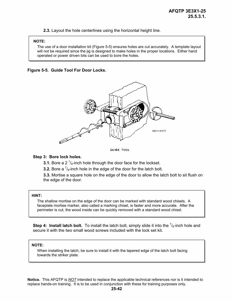
2.3. Layout the hole centerlines using the horizontal height line.
NOTE: The use of a door installation kit (Figure 5-5) ensures holes are cut accurately. A template layout will not be required since the jig is designed to make holes in the proper locations. Either hand operated or power driven bits can be used to bore the holes.
Figure 5-5. Guide Tool For Door Locks.
Step 3: Bore lock holes. 3.1. Bore a 2 1/8-inch hole through the door face for the lockset. 3.2. Bore a 7/8-inch hole in the edge of the door for the latch bolt. 3.3. Mortise a square hole on the edge of the door to allow the latch bolt to sit flush on the edge of the door.
HINT: The shallow mortise on the edge of the door can be marked with standard wood chisels. A faceplate mortise marker, also called a marking chisel, is faster and more accurate. After the perimeter is cut, the wood inside can be quickly removed with a standard wood chisel.
Step 4: Install latch bolt. To install the latch bolt, simply slide it into the 7/8-inch hole and secure it with the two small wood screws included with the lock set kit.
NOTE: When installing the latch, be sure to install it with the tapered edge of the latch bolt facing towards the striker plate.
Notice. This AFQTP is NOT intended to replace the applicable technical references nor is it intended to replace hands-on training. It is to be used in conjunction with these for training purposes only.
25-42
AFQTP 3E3X1-25 25.5.3.1.
Step 5: Install striker plate.
5.1. Mark the height and centerline on the jamb. The centerline must be the same distance from the stop as the latch case centerline is from the edge of the door. 5.2. Cut the mortise in the jamb to fit the box and strike plate. 5.3. Insert the pieces and tighten screws securely.
Step 6: Install lock. 6.1. With the latch bolt in place, insert the lock assembly in the 2 1/8-inch hole, making sure that the lock case hooks the retainer legs and the retractor hooks the bolt tails. 6.2. DO NOT FORCE. Forcing the parts together may bend them.
Step 7: Adjust lock. 7.1. To adjust the lock for a 1 3/8-inch door, unscrew the outside rose plate to 5/16-inch from the case cutout. 7.2. To adjust it for a 1 3/4-inch door, unscrew the outside rose plate to provide 1/2-inch between the rose plate and the case cutout. 7.3. To adjust it for any thickness between 1 3/8 and 1 3/4-inches, set the rose plate at a suitable intermediate position (see Figure 5-4).
Step 8: Install rose plate. 8.1. Slip on the rose plate (“Top” up) and locate screw holes on vertical centerline. 8.2. Insert machine screws and tighten alternately to obtain secure attachment.
8.3. Check the knob function to ensure the lock doesn’t bind nor stick. If it is binding or sticking, loosen the rose plate screws until the problem is fixed.
Step 9: Install inner rose. Place the inside rose over the rose plate with the notch in the rose over the spring retainer and snap the rose down so that the rose is flush with the door.
Step 10: Install inside knob. 10.1. Align the lug on the inside of the knob with the narrow slot on the spindle side. 10.2. Push the knob all the way in until the retainer clicks into the slot on the knob.
Step 11: Check operation. Turn the knob several times for any binding.
Step 12: Clean up area.
Notice. This AFQTP is NOT intended to replace the applicable technical references nor is it intended to replace hands-on training. It is to be used in conjunction with these for training purposes only.
25-43

AFQTP 3E3X1-25 25.5.3.1.
REVIEW QUESTIONS FOR
INSTALL CYLINDER LOCKS
QUESTION ANSWER 1. How many holes are needed in the door
face to install a cylinder lock? a. 1. b. 2. c. 3. d. None.
2. What is the normal height in inches of a cylinder lock?
a. 24-inches. b. 34-inches. c. 38-inches. d. 48-inches.
3. The hole size for the cylinder should be? a. 7/8-inch. b. 1 3/4-inch. c. 2 1/8-inch. d. 2 7/8-inch.
4. What should be done after the hole is drilled in the door edge for the latch?
a. Install the latch unit. b. Install the strike plate. c. Drill the hole for the cylinder. d. Cut the shallow mortise for the latch
faceplate.
5. What optional tool can be used to ensure holes are accurately cut?
a. Router. b. Template. c. Chisel set. d. Door installation kit.
6. When installing the lock, what should you make sure of?
a. The lock case hooks on the retainer legs. b. The retractor hooks on the retainer legs. c. The lock case hooks on the bolt tails. d. The retractor hooks on the latch bolt.
7. What adjustment should be made to the outside rose plate for a 1 3/4-inch door?
a. Unscrew the outside rose plate 5/16-inch from case cutout.
b. Set the rose plate at a suitable intermediate position.
c. Unscrew the outside rose plate 1/2-inch from case cutout.
d. Set the rose plate 1/2-inch from the intermediate position.
8. The final step to installing a cylinder lock is?
a. Install rose plate. b. Install inside rose. c. Install inside knob. d. Install outside knob.
Notice. This AFQTP is NOT intended to replace the applicable technical references nor is it intended to replace hands-on training. It is to be used in conjunction with these for training purposes only.
25-44
AFQTP 3E3X1-25 25.5.3.1.
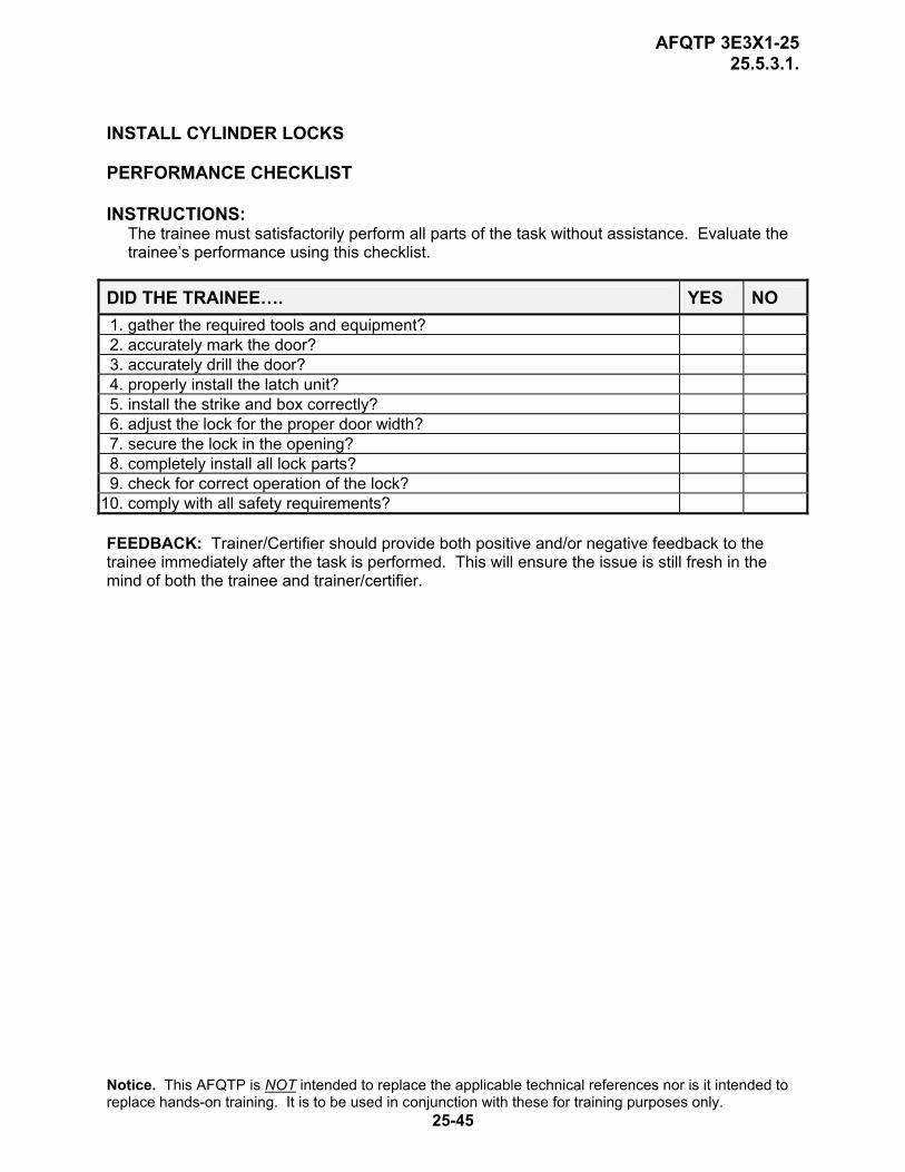
INSTALL CYLINDER LOCKS PERFORMANCE CHECKLIST INSTRUCTIONS:
The trainee must satisfactorily perform all parts of the task without assistance. Evaluate the trainee’s performance using this checklist.
DID THE TRAINEE…. YES NO 1. gather the required tools and equipment? 2. accurately mark the door? 3. accurately drill the door? 4. properly install the latch unit? 5. install the strike and box correctly? 6. adjust the lock for the proper door width? 7. secure the lock in the opening? 8. completely install all lock parts? 9. check for correct operation of the lock?
10. comply with all safety requirements? FEEDBACK: Trainer/Certifier should provide both positive and/or negative feedback to the trainee immediately after the task is performed. This will ensure the issue is still fresh in the mind of both the trainee and trainer/certifier.
Notice. This AFQTP is NOT intended to replace the applicable technical references nor is it intended to replace hands-on training. It is to be used in conjunction with these for training purposes only.
25-45

AFQTP 3E3X1-25 25.5.3.4.
PERSONNEL DOOR HARDWARE
INSTALL LOCKING DEVICES
MODULE 25 AFQTP UNIT 5
PANIC HARDWARE/EXIT DEVICE (25.5.3.4.)
Notice. This AFQTP is NOT intended to replace the applicable technical references nor is it intended to replace hands-on training. It is to be used in conjunction with these for training purposes only.
25-46

AFQTP 3E3X1-25 25.5.3.4.
INSTALL PANIC HARDWARE/EXIT DEVICE
Task Training Guide
STS Reference Number/Title:
25.5.3.4. – Install locking devices, panic hardware/exit device.
Training References:
1. Career Development Course (CDC) Structural Journeyman 3E351C, Volume 1, Unit 5, Section 5-2, Lesson 042; Inspecting and Maintaining Interior Doors.
2. Panic hardware/exit devices manufacturer instructions. 3. Builders Hardware Course for Locksmiths, No. 727. 4. Standard Building Code, 1120.7.2.
Prerequisites: 1. Possess as a minimum a 3E331 AFSC. 2. Review the following references:
2.1. CDC Structural Journeyman 3E351C, Volume 1, Unit 5, Section 5-2, Lesson 042. 2.2. Panic hardware/exit devices manufacturer instructions. 2.3. Standard Building Code, 1120.7.2.
Equipment/Tools Required:
1. General 3E3X1 tool kit. 2. Personal safety equipment. 3. 3/8-inch portable drill. 4. Extension cord (if needed). 5. Panic hardware kit.
Learning Objective:
Trainee upon completing this section should be able to describe the procedures for laying out and installing panic hardware.
Samples of Behavior:
1. Trainee will be able to successfully and safely install panic hardware.
2. Trainee will be able to inspect and adjust the operation of panic hardware.
Notes: Any safety violation is an automatic failure.
Notice. This AFQTP is NOT intended to replace the applicable technical references nor is it intended to replace hands-on training. It is to be used in conjunction with these for training purposes only.
25-47

AFQTP 3E3X1-25 25.5.3.4.
INSTALL PANIC HARDWARE/EXIT DEVICE
1. Background. Another type of locking device commonly used on doors is panic hardware. It is often used on exit doors in public buildings. It acts more as an unlocking device rather than a locking device. It provides emergency exit capability in the event of a panic—hence the name. With the standard cylinder lock, it may be difficult to open a door when pressure is placed on it. Panic hardware eliminates this problem by use of a horizontal bar that releases the lock whenever pressure is placed on it. Even an unconscious person falling against the door will open it and free the people behind. As a structural journeyman, you may be tasked to install or repair these devices. Panic hardware that is not functioning properly may mean the difference between life and death. 2. General Information. Panic hardware varies widely among manufacturers, so always follow the manufacturer’s instructions carefully. There are certain basic procedures that you need to follow when installing any panic hardware.
2.1. Establish the centerline for the hardware on the door and stop.
2.2. Use the templates that come with the hardware. Spot and drill the template holes.
2.3. Mount the hardware according to the manufacturer’s specification.
2.4. After the installation is complete, perform an operational check to ensure the hardware opens and closes properly.
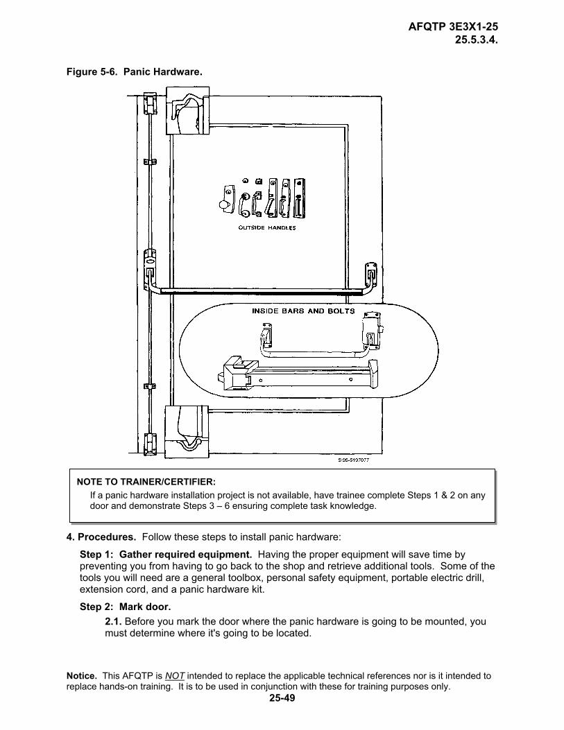
3. Panic Hardware Types (Figure 5-6). There are three basic types of panic hardware, Rim, Mortise lock, and Vertical Rod. All three types have similar components. They consist of two cases or lock bodies and a cross bar.
3.1. The Rim panic exit device is designed to be mounted to the inside door surface, exactly as a rim lock would be mounted. In the rim exit device, the latch bolt and the latching mechanism operation parts are contained within the active case: thus, a rim-mounted strike is used. For this type of installation, there is no door mortising or cutout. When installed, the cross bar controls the latch bolt retraction.
3.2. The Mortise lock panic exit device also is mounted to the inside surface of the door but it is used with a mortise lockset. The installation consists of the mortise lockset that is mortised into the door and a panic exit device installed on the door surface. The active case of the exit device, however, is positioned so that an arm extending from it will contact the mortise lock latch retracting arms. The opening action transfers from the cross bar to the latch bolt by a series of related levers.
3.3. The Vertical Rod exit device also is surface mounted but it is designed to place its latch bolts at the top and bottom of the door. In this type of installation, the usual active and support case is mounted to place the cross bar across the door. At the active case edge, however, vertical rods extend up and down from the active case to connect with latch bolts at the top and bottom edges. Instructions furnished by the manufacturer should be carefully followed. Procedures for all panic hardware will be similar, however the installation details will vary slightly.
Notice. This AFQTP is NOT intended to replace the applicable technical references nor is it intended to replace hands-on training. It is to be used in conjunction with these for training purposes only.
25-48
AFQTP 3E3X1-25 25.5.3.4.
Figure 5-6. Panic Hardware.
NOTE TO TRAINER/CERTIFIER: If a panic hardware installation project is not available, have trainee complete Steps 1 & 2 on any door and demonstrate Steps 3 – 6 ensuring complete task knowledge.
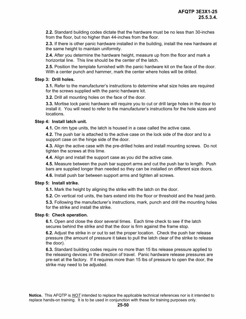
4. Procedures. Follow these steps to install panic hardware:
Step 1: Gather required equipment. Having the proper equipment will save time by preventing you from having to go back to the shop and retrieve additional tools. Some of the tools you will need are a general toolbox, personal safety equipment, portable electric drill, extension cord, and a panic hardware kit.
Step 2: Mark door. 2.1. Before you mark the door where the panic hardware is going to be mounted, you must determine where it's going to be located.
Notice. This AFQTP is NOT intended to replace the applicable technical references nor is it intended to replace hands-on training. It is to be used in conjunction with these for training purposes only.
25-49
AFQTP 3E3X1-25 25.5.3.4.
2.2. Standard building codes dictate that the hardware must be no less than 30-inches from the floor, but no higher than 44-inches from the floor. 2.3. If there is other panic hardware installed in the building, install the new hardware at the same height to maintain uniformity. 2.4. After you determine the hardware height, measure up from the floor and mark a horizontal line. This line should be the center of the latch. 2.5. Position the template furnished with the panic hardware kit on the face of the door. With a center punch and hammer, mark the center where holes will be drilled.
Step 3: Drill holes. 3.1. Refer to the manufacturer’s instructions to determine what size holes are required for the screws supplied with the panic hardware kit. 3.2. Drill all mounting holes on the face of the door. 3.3. Mortise lock panic hardware will require you to cut or drill large holes in the door to install it. You will need to refer to the manufacturer’s instructions for the hole sizes and locations.
Step 4: Install latch unit. 4.1. On rim type units, the latch is housed in a case called the active case. 4.2. The push bar is attached to the active case on the lock side of the door and to a support case on the hinge side of the door. 4.3. Align the active case with the pre-drilled holes and install mounting screws. Do not tighten the screws at this time. 4.4. Align and install the support case as you did the active case. 4.5. Measure between the push bar support arms and cut the push bar to length. Push bars are supplied longer than needed so they can be installed on different size doors. 4.6. Install push bar between support arms and tighten all screws.
Step 5: Install strike. 5.1. Mark the height by aligning the strike with the latch on the door. 5.2. On vertical rod units, the bars extend into the floor or threshold and the head jamb. 5.3. Following the manufacturer’s instructions, mark, punch and drill the mounting holes for the strike and install the strike.
Step 6: Check operation. 6.1. Open and close the door several times. Each time check to see if the latch secures behind the strike and that the door is firm against the frame stop. 6.2. Adjust the strike in or out to set the proper location. Check the push bar release pressure (the amount of pressure it takes to pull the latch clear of the strike to release the door). 6.3. Standard building codes require no more than 15 lbs release pressure applied to the releasing devices in the direction of travel. Panic hardware release pressures are pre-set at the factory. If it requires more than 15 lbs of pressure to open the door, the strike may need to be adjusted.
Notice. This AFQTP is NOT intended to replace the applicable technical references nor is it intended to replace hands-on training. It is to be used in conjunction with these for training purposes only.
25-50
AFQTP 3E3X1-25 25.5.3.4.
REVIEW QUESTIONS FOR
INSTALL PANIC HARDWARE/EXIT DEVICE
QUESTION ANSWER 1. Which type of locking device is intended
more for unlocking than for locking? a. Cylinder. b. Tubular. c. Mortise. d. Panic.
2. The three basic types of panic hardware are rim mounted, vertical rod, and _______.
a. mortise. b. cylinder. c. tubular. d. panic.
3. Panic hardware should be installed no more than?
a. 44-inches from the top of the threshold. b. 44-inches from the floor. c. 30-inches from the top of the threshold. d. 30-inches from the floor.
4. What is the first step to installing panic hardware?
a. Drill holes from mounting. b. Find the height line for the strike. c. Establish a centerline for the hardware. d. Adjust door to required release pressure.
5. What determines what size holes should be pre-drilled in the face of the door?
a. Size of the screw used. b. Size of the drill bit used. c. Length of screws used. d. Drill bit sizes available.
6. What is the final step in installing the latch cases?
a. Find the height line for the strike. b. Cut the push bar to length. c. Drill hole for mounting. d. Tighten all screws.
7. You should install the strike before you install the latch cases.
a. True. b. False.
8. What is the Standard Building Code release pressure for panic hardware?
a. 10 lbs. b. 15 lbs. c. 20 lbs. d. 25 lbs.
Notice. This AFQTP is NOT intended to replace the applicable technical references nor is it intended to replace hands-on training. It is to be used in conjunction with these for training purposes only.
25-51

AFQTP 3E3X1-25 25.5.3.5.
INSTALL PANIC HARDWARE/EXIT DEVICE PERFORMANCE CHECKLIST INSTRUCTIONS:
The trainee must satisfactorily perform all parts of the task without assistance. Evaluate the trainee’s performance using this checklist.
DID THE TRAINEE…. YES NO 1. gather the required tools, material, and equipment? 2. properly mark the door for centerline? 3. properly drill holes for hardware? 4. properly install latch cases? 5. properly install latch strike? 6. properly check panic hardware operation? 7. comply with all safety requirements? FEEDBACK: Trainer/Certifier should provide both positive and/or negative feedback to the trainee immediately after the task is performed. This will ensure the issue is still fresh in the mind of both the trainee and trainer/certifier.
Notice. This AFQTP is NOT intended to replace the applicable technical references nor is it intended to replace hands-on training. It is to be used in conjunction with these for training purposes only.
25-52
AFQTP 3E3X1-25 25.5.3.5.
PERSONNEL DOOR HARDWARE
INSTALL LOCKING DEVICES
MODULE 25 AFQTP UNIT 5
INSTALL HINGES (25.5.3.5.)
Notice. This AFQTP is NOT intended to replace the applicable technical references nor is it intended to replace hands-on training. It is to be used in conjunction with these for training purposes only.
25-53
AFQTP 3E3X1-25 25.5.3.5.
INSTALL HINGES
Task Training Guide
STS Reference Number/Title:
25.5.3.5. - Install hinges.
Training References:
1. Career Development Course (CDC) Structural Journeyman 3E351C, Volume 1, Unit 5, Section 5-2, Lesson 042; Inspecting and Maintaining Interior Doors.
2. Commercial Manual, Modern Carpentry by Willis H. Wagner, 1992.
3. Hinge manufacturer instructions. 4. Navy Advancement Training (NAVEDTRA) Course 14044,
Builders 3 & 2,Volume 2.
Prerequisites: 1. Possess as a minimum a 3E331 AFSC. 2. Review the following references:
2.1. CDC Structural Journeyman 3E351C, Volume 1, Unit 5, Section 5-2. 2.2. Modern Carpentry, Unit 17, pg. 429-30. 2.3. Hinge manufacturer instructions. 2.4. NAVEDTRA 14044, Chapter 6, Door Hardware Installation pg. 6-18.
Equipment/Tools Required:
1. General 3E3X1 tool kit. 2. Personal safety equipment. 3. 2”x4”x7’ lumber or wood personnel door unit. 4. 3 1/2-inch or 4-inch door hinges with screws. 5. 6-foot stepladder (if needed). 6. Wooden wedge. 7. 4d finish nails. 8. Door holder.
Learning Objective:
Trainee should be able to install hinges on a wood personnel door unit.
Samples of Behavior:
Trainee should be able to successfully and safely install hinges on a wood personnel door unit.
Notes: Any safety violation is an automatic failure.
Notice. This AFQTP is NOT intended to replace the applicable technical references nor is it intended to replace hands-on training. It is to be used in conjunction with these for training purposes only.
25-54
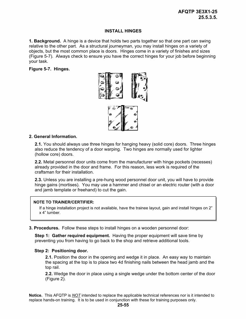
AFQTP 3E3X1-25 25.5.3.5.
INSTALL HINGES
1. Background. A hinge is a device that holds two parts together so that one part can swing relative to the other part. As a structural journeyman, you may install hinges on a variety of objects, but the most common place is doors. Hinges come in a variety of finishes and sizes (Figure 5-7). Always check to ensure you have the correct hinges for your job before beginning your task.
Figure 5-7. Hinges.
2. General Information. 2.1. You should always use three hinges for hanging heavy (solid core) doors. Three hinges also reduce the tendency of a door warping. Two hinges are normally used for lighter (hollow core) doors.
2.2. Metal personnel door units come from the manufacturer with hinge pockets (recesses) already provided in the door and frame. For this reason, less work is required of the craftsman for their installation.
2.3. Unless you are installing a pre-hung wood personnel door unit, you will have to provide hinge gains (mortises). You may use a hammer and chisel or an electric router (with a door and jamb template or freehand) to cut the gain.
NOTE TO TRAINER/CERTIFIER: If a hinge installation project is not available, have the trainee layout, gain and install hinges on 2” x 4” lumber.
3. Procedures. Follow these steps to install hinges on a wooden personnel door:
Step 1: Gather required equipment. Having the proper equipment will save time by preventing you from having to go back to the shop and retrieve additional tools.
Step 2: Positioning door. 2.1. Position the door in the opening and wedge it in place. An easy way to maintain the spacing at the top is to place two 4d finishing nails between the head jamb and the top rail. 2.2. Wedge the door in place using a single wedge under the bottom center of the door (Figure 2).
Notice. This AFQTP is NOT intended to replace the applicable technical references nor is it intended to replace hands-on training. It is to be used in conjunction with these for training purposes only.
25-55

AFQTP 3E3X1-25 25.5.3.5.
Figure 5-8. Setting Interior Doorframe. Step 3: Layout and mark hinge gains.
3.1. Mark hinge locations on the stile and jamb 7 inches from the top of the door and 11 inches from the bottom of the door as shown in Figure 5-8. 3.2. If the unit is to have a third hinge, center it between the first two. 3.3. After marking hinge locations, remove the door from the opening and place it in a door holder. 3.4. Mark the length of gains with the hinge itself. This distance is commonly 3 1/2-inches or 4-inches. 3.5. Mark the gain widths with a combination square. 3.6. There should be about a 3/16-inch setback distance from gain to door face. 3.7. The depth of the gains must be equal to the thickness of the hinge. Using a combination square, mark for this thickness on the jamb edge and the door face.
Figure 5-9. Mortising A Door For Butt Joints. Step 4: Mortising hinge gains.
4.1. Use a wood chisel to mortise hinge gains in both the jamb and the door (Figures 5-9 & 5-10). 4.2. It's best to choose a chisel as wide as the hinge gain. 4.3. Be sure not to remove too much material. An incorrect gain may keep the door from operating smoothly.
NOTE TO TRAINER: If the 2”x4” method is used, insert hinges and screw them down. If not flush, remove and take out more material, until flush. Stop here and proceed to evaluation
Notice. This AFQTP is NOT intended to replace the applicable technical references nor is it intended to replace hands-on training. It is to be used in conjunction with these for training purposes only.
25-56
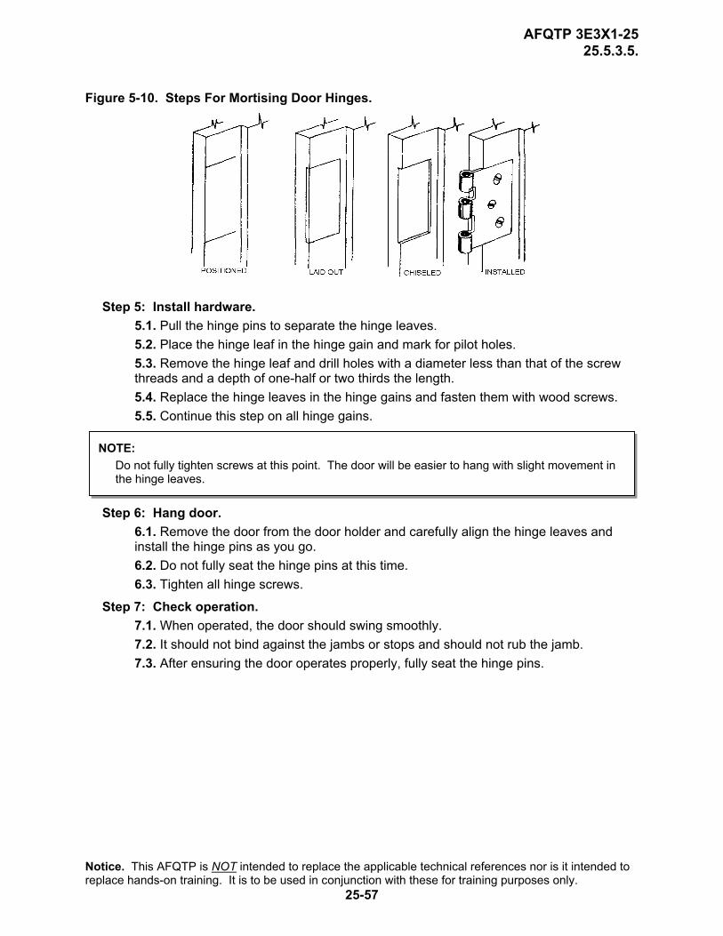
AFQTP 3E3X1-25 25.5.3.5.
Figure 5-10. Steps For Mortising Door Hinges.
Step 5: Install hardware. 5.1. Pull the hinge pins to separate the hinge leaves. 5.2. Place the hinge leaf in the hinge gain and mark for pilot holes. 5.3. Remove the hinge leaf and drill holes with a diameter less than that of the screw threads and a depth of one-half or two thirds the length. 5.4. Replace the hinge leaves in the hinge gains and fasten them with wood screws. 5.5. Continue this step on all hinge gains.
NOTE: Do not fully tighten screws at this point. The door will be easier to hang with slight movement in the hinge leaves.
Step 6: Hang door. 6.1. Remove the door from the door holder and carefully align the hinge leaves and install the hinge pins as you go. 6.2. Do not fully seat the hinge pins at this time. 6.3. Tighten all hinge screws.
Step 7: Check operation. 7.1. When operated, the door should swing smoothly. 7.2. It should not bind against the jambs or stops and should not rub the jamb. 7.3. After ensuring the door operates properly, fully seat the hinge pins.
Notice. This AFQTP is NOT intended to replace the applicable technical references nor is it intended to replace hands-on training. It is to be used in conjunction with these for training purposes only.
25-57
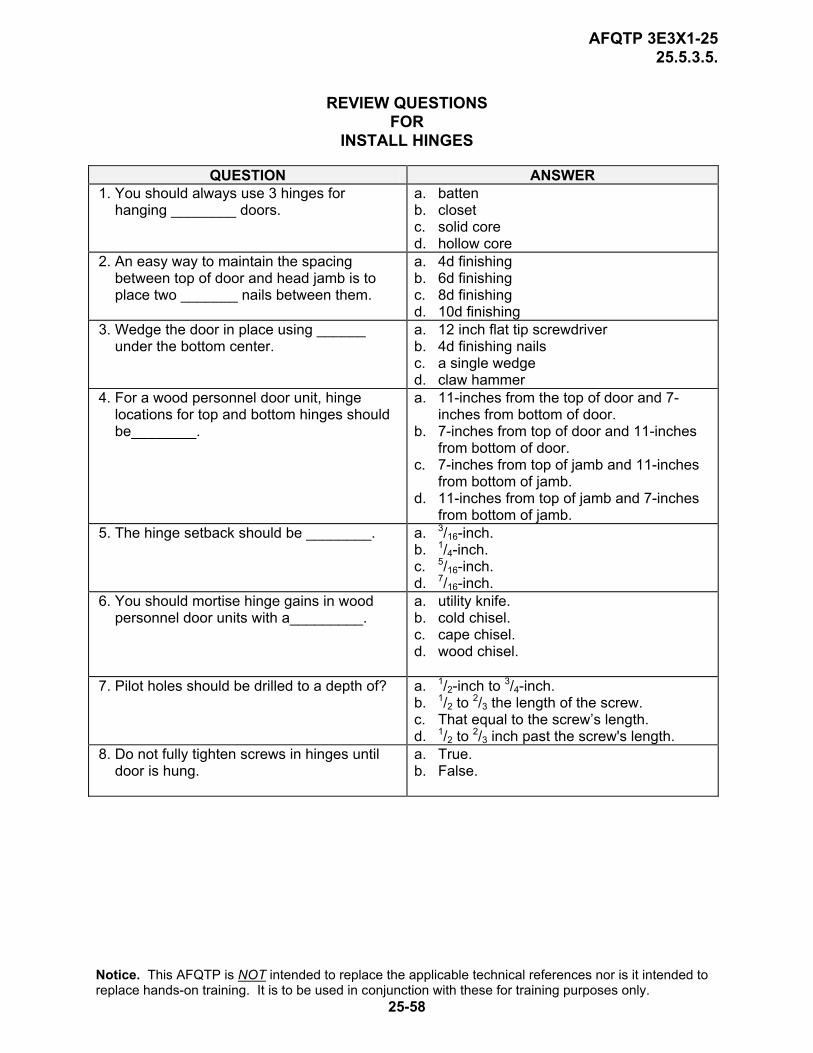
AFQTP 3E3X1-25 25.5.3.5.
REVIEW QUESTIONS
FOR INSTALL HINGES
QUESTION ANSWER 1. You should always use 3 hinges for
hanging ________ doors. a. batten b. closet c. solid core d. hollow core
2. An easy way to maintain the spacing between top of door and head jamb is to place two _______ nails between them.
a. 4d finishing b. 6d finishing c. 8d finishing d. 10d finishing
3. Wedge the door in place using ______ under the bottom center.
a. 12 inch flat tip screwdriver b. 4d finishing nails c. a single wedge d. claw hammer
4. For a wood personnel door unit, hinge locations for top and bottom hinges should be________.
a. 11-inches from the top of door and 7-inches from bottom of door.
b. 7-inches from top of door and 11-inches from bottom of door.
c. 7-inches from top of jamb and 11-inches from bottom of jamb.
d. 11-inches from top of jamb and 7-inches from bottom of jamb.
5. The hinge setback should be ________. a. 3/16-inch. b. 1/4-inch. c. 5/16-inch. d. 7/16-inch.
6. You should mortise hinge gains in wood personnel door units with a_________.
a. utility knife. b. cold chisel. c. cape chisel. d. wood chisel.
7. Pilot holes should be drilled to a depth of? a. 1/2-inch to 3/4-inch. b. 1/2 to 2/3 the length of the screw. c. That equal to the screw’s length. d. 1/2 to 2/3 inch past the screw's length.
8. Do not fully tighten screws in hinges until door is hung.
a. True. b. False.
Notice. This AFQTP is NOT intended to replace the applicable technical references nor is it intended to replace hands-on training. It is to be used in conjunction with these for training purposes only.
25-58

AFQTP 3E3X1-25 25.5.3.5.
INSTALL HINGES PERFORMANCE CHECKLIST INSTRUCTIONS:
The trainee must satisfactorily perform all parts of the task without assistance. Evaluate the trainee’s performance using this checklist.
DID THE TRAINEE…. YES NO 1. gather the required tools, material, and equipment? 2. correctly position the door in opening? (not evaluated for 2”x4” method) 3. correctly layout and mark for hinge gains? 4. mortise the gains correctly and neatly? 5. correctly install hinges? 6. correctly hang door? (not evaluated for 2”x4” method) 7. check for proper operation? (not evaluated for 2”x4” method) 8. comply with all safety requirements? FEEDBACK: Trainer/Certifier should provide both positive and/or negative feedback to the trainee immediately after the task is performed. This will ensure the issue is still fresh in the mind of both the trainee and trainer/certifier.
Notice. This AFQTP is NOT intended to replace the applicable technical references nor is it intended to replace hands-on training. It is to be used in conjunction with these for training purposes only.
25-59

AFQTP 3E3X1-25 KEY
Air Force Civil Engineer
QUALIFICATION TRAINING PACKAGE (QTP)
REVIEW ANSWER KEY
FOR
STRUCTURAL (3E3X1)
MODULE 25
PERSONNEL DOOR AND WINDOW MAINTENANCE
Notice. This AFQTP is NOT intended to replace the applicable technical references nor is it intended to replace hands-on training. It is to be used in conjunction with these for training purposes only.
Key-1
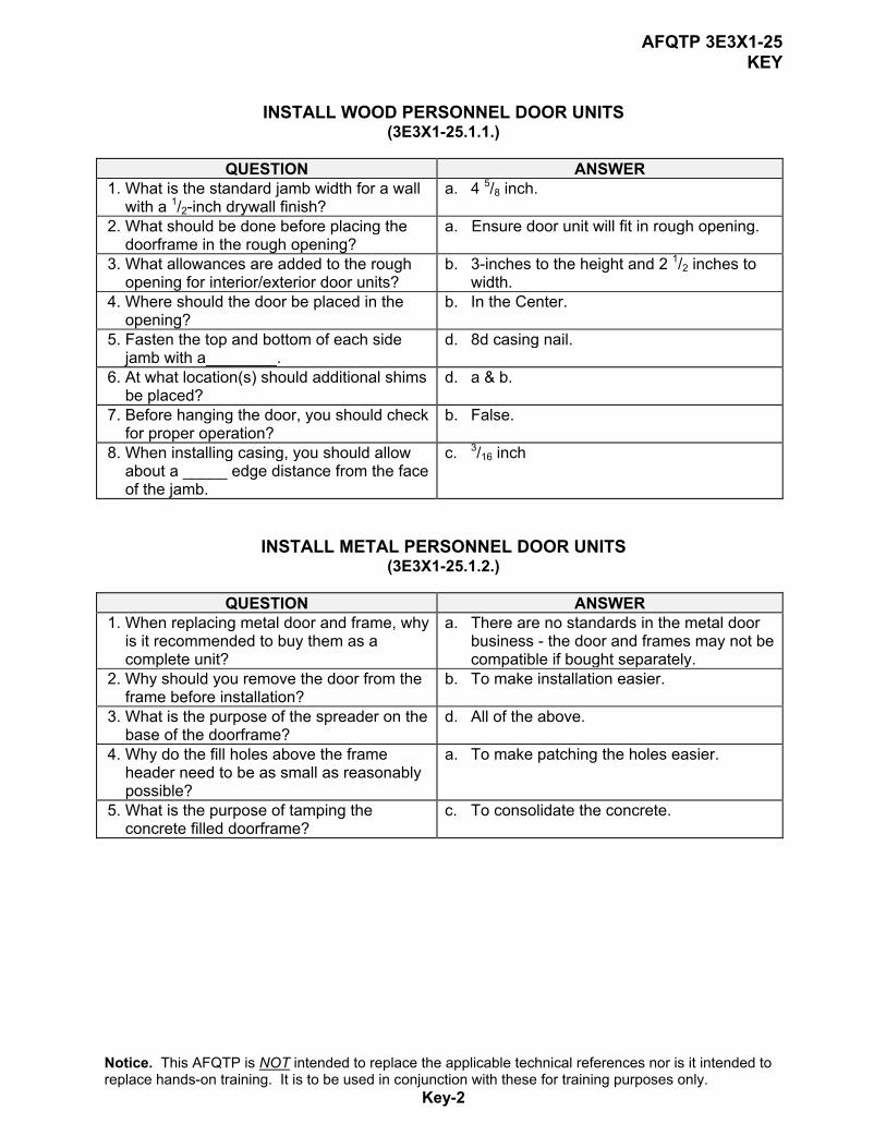
AFQTP 3E3X1-25 KEY
INSTALL WOOD PERSONNEL DOOR UNITS
(3E3X1-25.1.1.)
QUESTION ANSWER 1. What is the standard jamb width for a wall
with a 1/2-inch drywall finish? a. 4 5/8 inch.
2. What should be done before placing the doorframe in the rough opening?
a. Ensure door unit will fit in rough opening.
3. What allowances are added to the rough opening for interior/exterior door units?
b. 3-inches to the height and 2 1/2 inches to width.
4. Where should the door be placed in the opening?
b. In the Center.
5. Fasten the top and bottom of each side jamb with a________.
d. 8d casing nail.
6. At what location(s) should additional shims be placed?
d. a & b.
7. Before hanging the door, you should check for proper operation?
b. False.
8. When installing casing, you should allow about a _____ edge distance from the face of the jamb.
c. 3/16 inch
INSTALL METAL PERSONNEL DOOR UNITS (3E3X1-25.1.2.)
QUESTION ANSWER 1. When replacing metal door and frame, why
is it recommended to buy them as a complete unit?
a. There are no standards in the metal door business - the door and frames may not be compatible if bought separately.
2. Why should you remove the door from the frame before installation?
b. To make installation easier.
3. What is the purpose of the spreader on the base of the doorframe?
d. All of the above.
4. Why do the fill holes above the frame header need to be as small as reasonably possible?
a. To make patching the holes easier.
5. What is the purpose of tamping the concrete filled doorframe?
c. To consolidate the concrete.
Notice. This AFQTP is NOT intended to replace the applicable technical references nor is it intended to replace hands-on training. It is to be used in conjunction with these for training purposes only.
Key-2
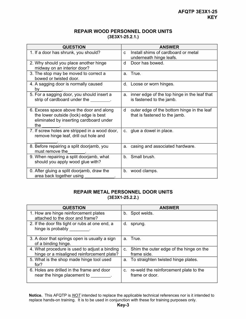
AFQTP 3E3X1-25 KEY
REPAIR WOOD PERSONNEL DOOR UNITS
(3E3X1-25.2.1.)
QUESTION ANSWER 1. If a door has shrunk, you should? c Install shims of cardboard or metal
underneath hinge leafs. 2. Why should you place another hinge
midway on an interior door? d Door has bowed.
3. The stop may be moved to correct a bowed or twisted door.
a. True.
4. A sagging door is normally caused by_________.
d. Loose or worn hinges.
5. For a sagging door, you should insert a strip of cardboard under the ________.
a. inner edge of the top hinge in the leaf that is fastened to the jamb.
6. Excess space above the door and along
the lower outside (lock) edge is best eliminated by inserting cardboard under the _______.
d outer edge of the bottom hinge in the leaf that is fastened to the jamb.
7. If screw holes are stripped in a wood door, remove hinge leaf, drill out hole and _________.
c. glue a dowel in place.
8. Before repairing a split doorjamb, you must remove the_______.
a. casing and associated hardware.
9. When repairing a split doorjamb, what should you apply wood glue with?
b. Small brush.
10. After gluing a split doorjamb, draw the area back together using ____________.
b. wood clamps.
REPAIR METAL PERSONNEL DOOR UNITS (3E3X1-25.2.2.)
QUESTION ANSWER 1. How are hinge reinforcement plates
attached to the door and frame? b. Spot welds.
2. If the door fits tight or rubs at one end, a hinge is probably ________.
d. sprung.
3. A door that springs open is usually a sign of a binding hinge.
a. True.
4. What procedure is used to adjust a binding hinge or a misaligned reinforcement plate?
c. Shim the outer edge of the hinge on the frame side.
5. What is the shop made hinge tool used for?
a. To straighten twisted hinge plates.
6. Holes are drilled in the frame and door near the hinge placement to ________.
c. re-weld the reinforcement plate to the frame or door.
Notice. This AFQTP is NOT intended to replace the applicable technical references nor is it intended to replace hands-on training. It is to be used in conjunction with these for training purposes only.
Key-3
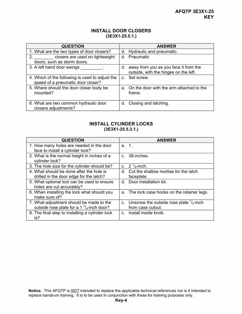
AFQTP 3E3X1-25 KEY
INSTALL DOOR CLOSERS
(3E3X1-25.5.1.)
QUESTION ANSWER 1. What are the two types of door closers? d. Hydraulic and pneumatic. 2. ________ closers are used on lightweight
doors, such as storm doors. d. Pneumatic
3. A left hand door swings _________. d. away from you as you face it from the outside, with the hinges on the left.
4. Which of the following is used to adjust the speed of a pneumatic door closer?
c. Set screw.
5. Where should the door closer body be mounted?
a. On the door with the arm attached to the frame.
6. What are two common hydraulic door
closers adjustments? d. Closing and latching.
INSTALL CYLINDER LOCKS (3E3X1-25.5.3.1.)
QUESTION ANSWER
1. How many holes are needed in the door face to install a cylinder lock?
a. 1.
2. What is the normal height in inches of a cylinder lock?
c. 38-inches.
3. The hole size for the cylinder should be? c. 2 1/8-inch. 4. What should be done after the hole is
drilled in the door edge for the latch? d. Cut the shallow mortise for the latch
faceplate. 5. What optional tool can be used to ensure
holes are cut accurately? d. Door installation kit.
6. When installing the lock what should you make sure of?
a. The lock case hooks on the retainer legs.
7. What adjustment should be made to the outside rose plate for a 1 3/4-inch door?
c. Unscrew the outside rose plate 1/2-inch from case cutout.
8. The final step to installing a cylinder lock is?
c. Install inside knob.
Notice. This AFQTP is NOT intended to replace the applicable technical references nor is it intended to replace hands-on training. It is to be used in conjunction with these for training purposes only.
Key-4

AFQTP 3E3X1-25 KEY
INSTALL PANIC HARDWARE/EXIT DEVICE
(3E3X1-25.5.3.4.)
QUESTION ANSWER 1. Which type of locking device is intended
more for unlocking than for locking? d. Panic.
2. The three basic types of panic hardware are rim mounted, vertical rod, and _______.
a. mortise.
3. Panic hardware should be installed no more than?
b. 44-inches from the floor.
4. What is the first step to installing panic hardware?
c. Establish a centerline for the hardware.
5. What determines what size holes should be pre-drilled in the face of the door?
a. Size of the screw used.
6. What is the final step in installing the latch cases?
d. Tighten all screws.
7. You should install the strike before you install the latch cases?
b. False.
8. What is the Standard Building Code release pressure for panic hardware?
b. 15 lbs.
INSTALL HINGES (3E3X1-25.5.3.5.)
QUESTION ANSWER 1. You should always use 3 hinges for
hanging ________ doors. c. solid core
2. An easy way to maintain the spacing between top of door and head jamb is to place two _______ nails between them.
a. 4d-finishing
3. Wedge the door in place using ______ under the bottom center.
c. a single wedge
4. For a wood personnel door unit, hinge locations for top and bottom hinges should be___________.
b. 7-inches from top of door and 11-inches from bottom of door.
5. The hinge setback should be ________. a. 3/16-inch.
6. You should mortise hinge gains in wood personnel door units with a_____.
d. wood chisel.
7. Pilot hole should be drilled to a depth of? b. 1/2 to 2/3 the length of the screw.
8. Do not fully tighten screws in hinges until door is hung?
a. True.
Notice. This AFQTP is NOT intended to replace the applicable technical references nor is it intended to replace hands-on training. It is to be used in conjunction with these for training purposes only.
Key-5

Appendix A
MEMORANDUM FOR HQ AFCESA/CEOF
139 Barnes Drive Suite 1 Tyndall AFB, FL 32403-5319
FROM: SUBJECT: Qualification Training Package Improvement 1. Identify module.
Module # and title__________________________________________________ 2. Identify improvement/correction section(s):
_____ STS Task Reference ______ Performance Checklist _____ Training Reference ______ Feedback _____ Evaluation Instructions ______ Format _____ Performance Resources ______ Other _____ Steps in Task Performance
3. Recommended changes--use a continuation sheet if necessary.
_________________________________________________________________________________________________________________________________________________________________________________________________________________________________________________________________________________________________________________________________________________________________________________________________________________________________________________________________________________________________________________________________________________________________________________________________________________________________________________________________________________
4. You may choose to call in your recommendations to DSN 523-6445 or FAX
DSN/Commercial 523-6488 or (850) 283-6488 or email [email protected]. 5. Thank you for your time and interest.
YOUR NAME, RANK, USAF Title/Position