Embed Size (px)
Citation preview

MILLAU BRIDGE

The Millau Viaduct is a cable-stayed road-bridge that
spans the valley of the river Tarn near Millau in
southern France.

In February 1995, on the basis of proposals of the architects and structural engineers, five general designs were identified.
Then, The solution of a cable-stayed bridge, presented by architects Norman Foster was declared the best.
In February 1995, on the basis of proposals of the architects and structural engineers, five general designs were identified.
Then, The solution of a cable-stayed bridge, presented by architects Norman Foster was declared the best.

Designed by the French structural engineer Michel
Virlogeux and British architect Norman Foster, it is
the tallest bridge in the world with one mast's summit at
343.0 metres above the base of the structure.
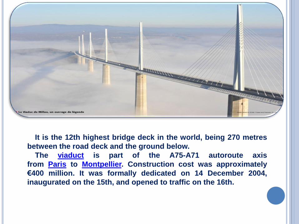
It is the 12th highest bridge deck in the world, being 270 metres
between the road deck and the ground below.
The viaduct is part of the A75-A71 autoroute axis
from Paris to Montpellier. Construction cost was approximately
€400 million. It was formally dedicated on 14 December 2004,
inaugurated on the 15th, and opened to traffic on the 16th.
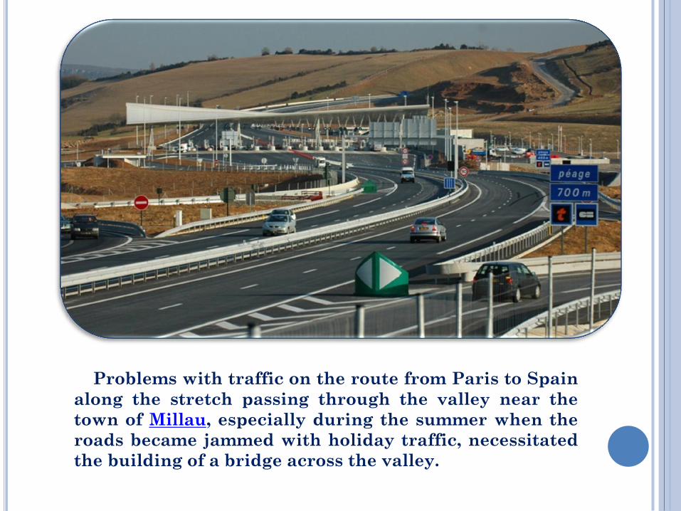
Problems with traffic on the route from Paris to Spain
along the stretch passing through the valley near the
town of Millau, especially during the summer when the
roads became jammed with holiday traffic, necessitated
the building of a bridge across the valley.

Construction Records
The bridge’s construction broke several records:
•The highest pylons in the world: pylons P2 and P3, 244.96 metres and
221.05 metres in height respectively, broke the French record previously
held by the Tulle and Verrières Viaducts and the world record previously
held by the Kochertal Viaduct (Germany), which is 181 metres at its
highest;
•The highest bridge tower in the world: the mast atop pylon P2 peaks at
343 metres

Costs and Resources
The bridge's construction cost up to €394 million,with a toll plaza 6 km
north of the viaduct costing an additional €20 million.
The project required about 127,000 cubic metres of concrete, 19,000
tonnes of steel for the reinforced concrete and 5,000 tonnes of pre-stressed
steel for the cables and shrouds. The builder claims that the lifetime of the
bridge will be at least 120 years.
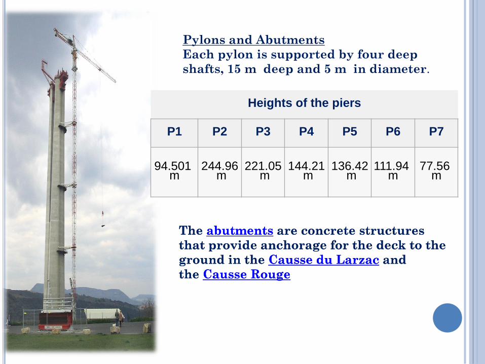
Heights of the piers
P1 P2 P3 P4 P5 P6 P7
94.501 m
244.96 m
221.05 m
144.21 m
136.42 m
111.94 m
77.56 m
Pylons and Abutments
Each pylon is supported by four deep
shafts, 15 m deep and 5 m in diameter.
The abutments are concrete structures
that provide anchorage for the deck to the
ground in the Causse du Larzac and
the Causse Rouge
Pylons and Abutments
Each pylon is supported by four deep
shafts, 15 m deep and 5 m in diameter.
The abutments are concrete structures
that provide anchorage for the deck to the
ground in the Causse du Larzac and
the Causse Rouge
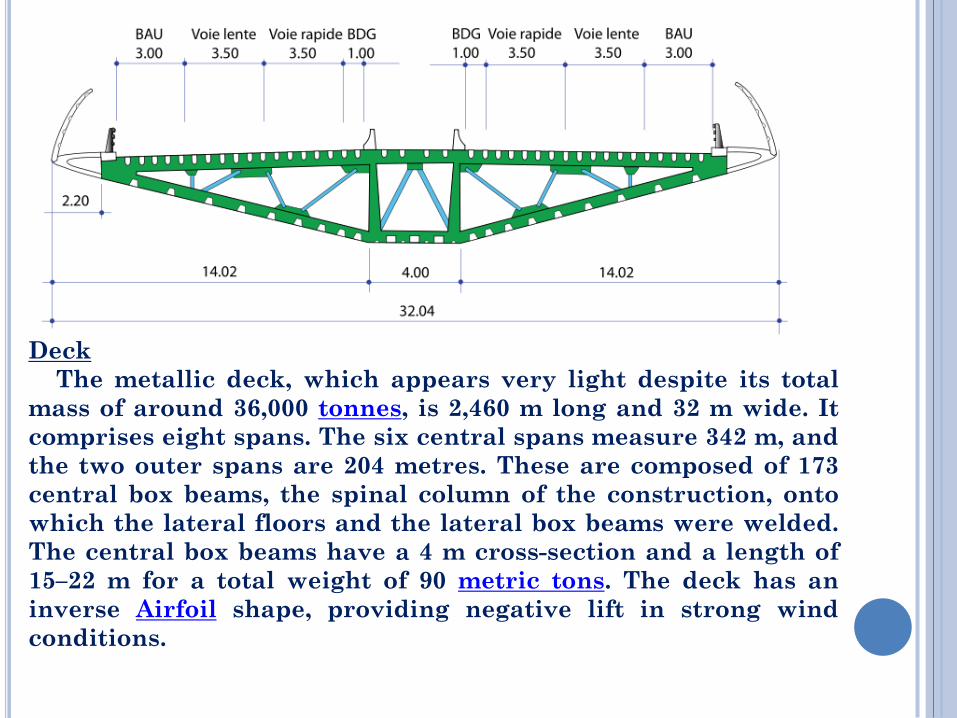
Deck
The metallic deck, which appears very light despite its total
mass of around 36,000 tonnes, is 2,460 m long and 32 m wide. It
comprises eight spans. The six central spans measure 342 m, and
the two outer spans are 204 metres. These are composed of 173
central box beams, the spinal column of the construction, onto
which the lateral floors and the lateral box beams were welded.
The central box beams have a 4 m cross-section and a length of
15–22 m for a total weight of 90 metric tons. The deck has an
inverse Airfoil shape, providing negative lift in strong wind
conditions.

Masts
The seven masts, each 87 m high and weighing around 700 tonnes
are set on top of the pylons. Between each of them, eleven stays
(metal cables) are anchored, providing support for the road deck.
Each mast of the viaduct is equipped with a monoaxial layer of eleven
pairs of stays laid face to face. Depending on their length, the stays were
made of 55 to 91 high tensile steelcables, or strands, themselves formed
of seven strands of steel. Each strand has triple protection
against corrosion. The exterior envelope of the stays is itself coated
along its entire length with a double helical weatherstrip. The idea is to
avoid running water which, in high winds, could cause vibration in the
stays and compromise the stability of the viaduct.
Stays

Surface To allow for deformations of the metal deck under traffic,
a special surface of modified bitumen was installed by
research teams from Appia. The surface is somewhat flexible
to adapt to deformations in the steel deck without cracking,
but it must nevertheless have sufficient strength to
withstand motorway conditions. The "ideal formula" was
found only after two years of research.

Construction
Two weeks after the laying of the first stone on 14 December
2001, the workers started to dig the deep shafts. There were 4
per pylon; 15 m deep and 5 m in diameter, assuring the stability
of the pylons. At the bottom of each pylon, a tread of 3–5 m in
thickness was installed to reinforce the effect of the deep shafts.
The 2,000 m3 of concrete necessary for the treads was poured at
the same time.

In March 2002, the pylons emerged from the ground. The
speed of construction then rapidly increased. Every three days,
each pylon increased in height by 4 m (13 ft). This performance
was mainly due to sliding shuttering. Thanks to a system of
shoe anchorages and fixed rails in the heart of the pylons, a
new layer of concrete could be poured every 20 minutes
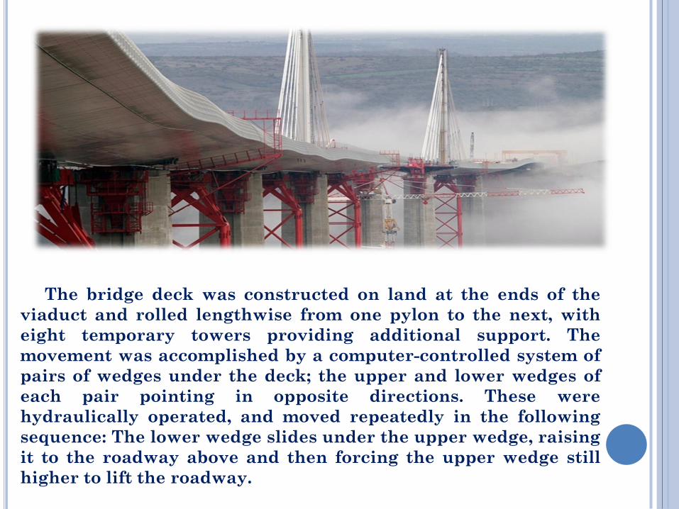
The bridge deck was constructed on land at the ends of the
viaduct and rolled lengthwise from one pylon to the next, with
eight temporary towers providing additional support. The
movement was accomplished by a computer-controlled system of
pairs of wedges under the deck; the upper and lower wedges of
each pair pointing in opposite directions. These were
hydraulically operated, and moved repeatedly in the following
sequence: The lower wedge slides under the upper wedge, raising
it to the roadway above and then forcing the upper wedge still
higher to lift the roadway.
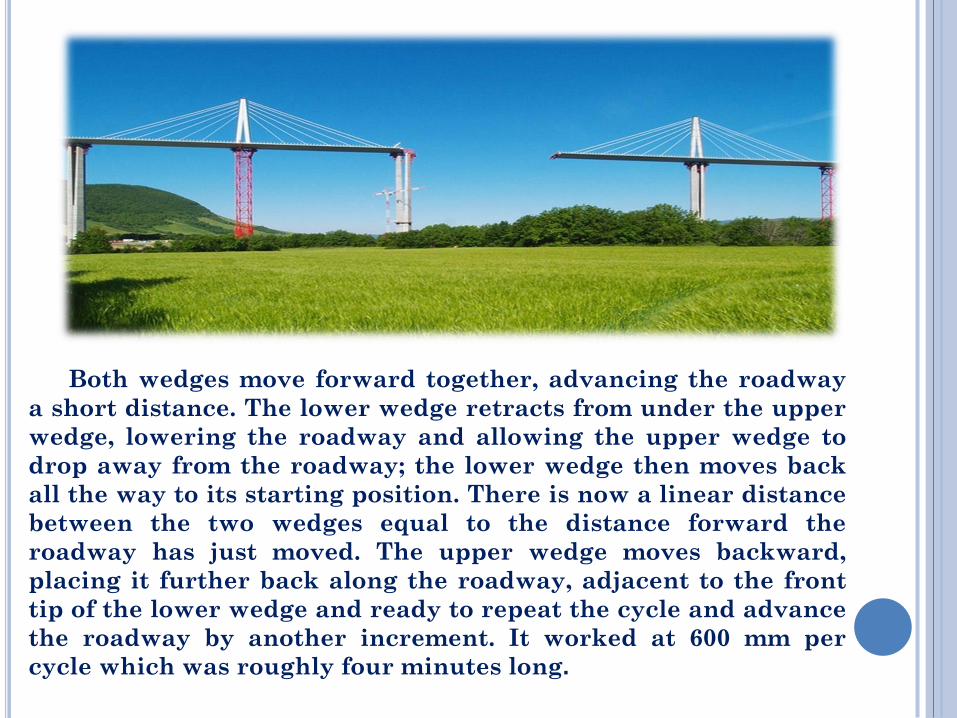
Both wedges move forward together, advancing the roadway
a short distance. The lower wedge retracts from under the upper
wedge, lowering the roadway and allowing the upper wedge to
drop away from the roadway; the lower wedge then moves back
all the way to its starting position. There is now a linear distance
between the two wedges equal to the distance forward the
roadway has just moved. The upper wedge moves backward,
placing it further back along the roadway, adjacent to the front
tip of the lower wedge and ready to repeat the cycle and advance
the roadway by another increment. It worked at 600 mm per
cycle which was roughly four minutes long.

The mast pieces were driven over the new deck lying down
horizontally. The pieces were joined to form the one complete
mast, still lying horizontally. The mast was then tilted upwards,
as one piece, at one time in a tricky operation. In this way each
mast was erected on top of the corresponding pylon. The stays
connecting the masts and the deck were then installed, and the
bridge was tensioned overall and weight tested. After this, the
temporary pylons could be removed.


![mixta combinada con pretensado exterior: el nuevo puente ... · M. Virlogeux (1993) [1] ha hecho un planteamiento interesante en este sentido, estableciendo dos posibles criterios](https://img.pdfslide.net/doc/110x75/5ac4a1967f8b9af91c8d2856/mixta-combinada-con-pretensado-exterior-el-nuevo-puente-virlogeux-1993.jpg)