Embed Size (px)
Citation preview


2

Contents Miller Decommissioning Programme
Miller Decommissioning Programme September 2011 i
Contents
Page
References ix
Terms and Abbreviations xiii Section Page
1 Introduction 1 1.1 Purpose 1 1.2 Scope 1
2 Executive Summary 5 2.1 Introduction 5 2.2 Recommendations 8 2.3 Legal Requirements 9 2.4 Principles Used to Assess Decommissioning Options 9
2.4.1 Method and Evaluation Process 10 2.4.2 Evaluation of Impacts 10 2.4.3 Assurance 11 2.4.4 External Stakeholder Consultation 12
2.5 Decommissioning Options Assessments 12 2.5.1 Well Abandonment and Conductor Removal 12 2.5.2 Topsides Modules Decommissioning 12 2.5.3 Jacket Decommissioning 13 2.5.4 Pipelines 16 2.5.5 Cuttings Pile 16 2.5.6 Seabed Debris and other Items 17 2.5.7 Onshore Treatment and Disposal of Materials 17
2.6 Schedule and Cost Summary 18 2.7 Legacy Activities 19
3 Background Information 21 3.1 Miller Field Development 21 3.2 Pipelines 21 3.3 Adjacent Facilities 22 3.4 Physical, Meteorological and Oceanographic Conditions 23 3.5 Commercial Fisheries 23
3.5.1 General 23 3.5.2 Fishing Methods 24 3.5.3 Landings Weights and Values 24 3.5.4 Fishing Effort 26 3.5.5 Vessel Tracking 26
3.6 Other Sea Users and Obstructions 28 3.6.1 Shipping 28 3.6.2 Wrecks 30 3.6.3 Military Activities 30 3.6.4 Submarine Cables 30

Miller Decommissioning Programme Contents
ii Miller Decommissioning Programme September 2011
Contents (cont'd)
Section Page
4 Description of Items to be Decommissioned 31 4.1 Introduction 31 4.2 Topsides Modules 31 4.3 Jacket and Drilling Template 33
4.3.1 Jacket 33 4.3.2 Drilling Template 37
4.4 Wells and Platform Conductors 37 4.5 Pipeline Spools, Umbilicals, SSIVs and Associated Items at Miller 38
4.5.1 Pipeline Descriptions 38 4.5.2 Items to be Removed 39
4.6 Cuttings Pile 40 4.7 Seabed Debris and Other Items 40
5 Inventory of Materials 43 5.1 Introduction 43 5.2 Topsides Modules 43 5.3 Jacket and Drilling Template 43 5.4 Wells and Platform Conductors 43 5.5 Pipeline Spools, Umbilicals, SSIVs and Associated Items at Miller 43 5.6 Cuttings Pile 43 5.7 Seabed Debris and Other Items 43
6 Removal and Disposal Options 49 6.1 Reuse, Alternative Use and Decommissioning Options 49
6.1.1 Reuse 49 6.1.2 Decommission 50
6.2 Assessment Methodology 50 6.2.1 Introduction 50 6.2.2 Decommissioning Studies 51 6.2.3 Jacket Comparative Assessment Studies 51 6.2.4 Independent Review 55 6.2.5 Stakeholder Consultation 56
6.3 Topsides Modules Decommissioning 56 6.4 Jacket Decommissioning 58
6.4.1 Introduction 58 6.4.2 Jacket Decommissioning Options 58 6.4.3 Jacket Removal Comparative Assessment 60 6.4.4 Jacket Comparative Assessment Conclusions 71
6.5 Drilling Template Decommissioning 74 6.6 Wells and Platform Conductors Decommissioning 74 6.7 Pipeline Spools, Umbilicals, SSIVs and Associated Items 74 6.8 Cuttings Pile Decommissioning 75

Contents Miller Decommissioning Programme
Miller Decommissioning Programme September 2011 iii
Contents (cont'd)
Section Page
7 Selected Removal and Disposal Option 77 7.1 Topsides Decommissioning 77
7.1.1 Introduction 77 7.1.2 Preparatory Work for Topsides Removal 77 7.1.3 Removal Methods 78 7.1.4 Onshore Disposal of Topsides 80 7.1.5 Topsides Removal Method Recommendation 82
7.2 Jacket Decommissioning 82 7.2.1 Introduction 82 7.2.2 Preparation for Removal 82 7.2.3 Contingent Measures 83 7.2.4 Jacket Removal Methods 83 7.2.5 Onshore Disposal 86 7.2.6 Jacket Removal Method Recommendation 87
7.3 Wells and Platform Conductors Decommissioning 87 7.4 Pipeline Spools, Umbilicals, SSIVs and Associated Items 87
7.4.1 Introduction 87 7.4.2 30in Gas Export Pipeline (PL-720) Disconnection 87 7.4.3 18in Oil Export (PL-722) Disconnection 88 7.4.4 16in Brae-Miller Linkline (PL-1971) Disconnection 89 7.4.5 Scope of Work 89 7.4.6 Monitoring Programme for Material Left on Seabed 90
7.5 Cuttings Pile Decommissioning 90
8 Wells 91 8.1 Introduction 91 8.2 Well Abandonment and Conductor Removal 91
9 Cuttings Pile 95 9.1 OSPAR Recommendation 2006/5 95 9.2 Miller Cuttings Pile 95
10 Environmental Impact Assessment 97 10.1 Introduction 97 10.2 Environmental Description 97
10.2.1 Hydrography 97 10.2.2 Meteorology 99 10.2.3 Sediment 100 10.2.4 Plankton and Primary Production 102 10.2.5 Seabed and Benthic Communities 103 10.2.6 Fish Populations 104 10.2.7 Spawning and Nursery Areas 104 10.2.8 Seabirds 105 10.2.9 Marine Mammals 107 10.2.10 Inshore and Coastal Areas 108

Miller Decommissioning Programme Contents
iv Miller Decommissioning Programme September 2011
Contents (cont'd)
Section Page
10.3 Conservation Interest 109 10.3.1 Offshore Conservation 109 10.3.2 Important Species 109 10.3.3 Cetaceans 109 10.3.4 Fish 109 10.3.5 Birds 110
10.4 Environmental Impact Assessment Methodology 110 10.4.1 General 110 10.4.2 Activities and Impact Categories 110 10.4.3 Environmental Issues Identification 110 10.4.4 Risk Matrices Population 111 10.4.5 Risk Rating Assignment 111 10.4.6 Significant Potential Impacts Screening 112
10.5 Offshore Impacts 113 10.5.1 Emissions to Air (Vessels) 113 10.5.2 Energy Use 116 10.5.3 Discharges to Sea 117 10.5.4 Underwater Noise 118
10.6 Onshore/Inshore Impacts 120 10.6.1 Waste 120 10.6.2 Onshore Energy Use and Atmospheric Emissions 122 10.6.3 Disturbance of Protected Sites 123 10.6.4 Interaction with Other Sea Users (Fishing Gear Impact) 124
10.7 Summary 124
11 Interested Party Consultation 125 11.1 Introduction 125 11.2 Consultation Process 125 11.3 Statutory Public Consultation 126 11.4 OSPAR Consultation 127 11.5 Letters from Section 29 Notice Holders 128
Appendix 11-A Scottish Fishermen's Federation Response and BP Reply 129
Appendix 11-B Northern Ireland Fishermen's Federation Response 133
Appendix 11-C Global Marine Systems Limited Response 135
Appendix 11-D Contracting Party Letters 137
Appendix 11-E Letters from Section 29 Notice Holders 145
12 Costs 153
13 Schedule 155

Contents Miller Decommissioning Programme
Miller Decommissioning Programme September 2011 v
Contents (cont'd)
Section Page
14 Project Management and Verification 157 14.1 Introduction 157 14.2 Operating Management System 157 14.3 Technical 158 14.4 Reporting 159 14.5 Verification 160
14.5.1 General 160 14.5.2 Miller Decommissioning Studies Independent Review Consultant 160
14.6 Licences Associated with Decommissioning Miller 160
15 Debris Clearance 163
16 Post–Decommissioning Monitoring and Maintenance 165 16.1 Post Decommissioning Monitoring 165 16.2 Legacy Activities 165
17 Supporting Studies 167
Addendum 1 Summary of Applicable Legislation 169
Figures
Figure Page
1.1 30in Gas Export Pipeline (PL-720/PL-833) and Control Umbilical 2
1.2 18in Oil Export Pipeline (PL-722) 2
1.3 16in Brae-Miller Linkline (PL-1971) and Control Umbilicals 3
2.1 Miller Field Location 5
2.2 Miller Topsides Showing the Modular Construction 6
2.3 Miller Jacket 7
2.4 Miller Decommissioning Indicative Schedule 18
3.1 Adjacent Facilities and Pipelines 22
3.2 Miller Platform Location in Relation to ICES Rectangles 24
3.3 Average Annual Values (2000 - 2007) by Vessel and Type of Fish 25
3.4 Average Annual Landings Weight (Tonnes) (2000 – 2007) by Vessel and
Type of Fish 25
3.5 Annual Fishing Effort (Days Fished between 2000 – 2007) by Vessel
Category 26
3.6 Annual Fishing Effort (Days Fished between 2000 – 2007) by Method in ICES
Rectangle 46F1 27
3.7 Average Monthly Fishing Effort (Days Fished between 2000 – 2007) by
Method in ICES Rectangle 46F1 27
3.8 Vessels Sighted in the Miller Area (2008) 28

Miller Decommissioning Programme Contents
vi Miller Decommissioning Programme September 2011
Figures (cont'd)
Figure Page
3.9 Shipping Routes Passing within 20km of Miller (Ref COAST Database) 29
4.1 Topsides Modules Showing the Modular Construction 32
4.2 Jacket Main Components 34
4.3 Relative Size of Jacket Footings to Person 35
4.4 Miller Drilling Template 37
4.5 Miller Pipelines 38
4.6 Miller Cuttings Pile Bathymetry 41
6.1 Indicative Topsides Removal Activity 57
6.2 Indicative Partial Jacket Removal showing Footings and Drilling Template 59
6.3 Indicative Partial Jacket Removal Activity 61
7.1 30in Gas Export Pipeline (PL-720/PL-833) Details 88
7.2 18in Oil Export Pipeline (PL-722) Details 88
7.3 16in Brae-Miller Linkline (PL-1971) Details 89
8.1 Typical Well Abandonment Showing Location of Cement Plugs 94
10.1 North Sea Current Regime 98
10.2 Miller Area Wind Rose Data 99
10.3 Miller Cuttings Pile Bathymetry 101
10.4 Spawning and Nursery Grounds around Miller 104
10.5 Block Specific Seabird Vulnerability to Surface Pollution around the Miller
Platform and Surrounding Area 106
10.6 Location of Cetacean Sightings in the Vicinity of the Miller Platform (2005) 107
10.7 Potential Dismantling Locations 108
13.1 Miller Decommissioning Indicative Schedule 155
Tables
Table Page
1.1 Miller Platform Section 29 Notice Holders 1
2.1 Miller Platform Section 29 Notice Holders 8
2.2 Assessment Criteria Acceptability Levels 11
2.3 Key Qualitative and Quantitative Factors for Jacket Removal Options
Summary 15
2.4 Rate of Oil Loss and Persistence over the Area of Contaminated Seabed –
OSPAR 2006/5 Thresholds and Miller Values 17
3.1 Physical, Meteorological and Oceanographic Conditions 23
3.2 Shipping Routes and Estimated Numbers of Vessels (excluding Miller/Brae
Traffic) (Ref COAST Database) 29

Contents Miller Decommissioning Programme
Miller Decommissioning Programme September 2011 vii
Tables (cont'd)
Table Page
4.1 Miller Topsides Modules Size and Weight 33
4.2 Miller Jacket Items Size and Weight 36
4.3 Miller Caissons 36
4.4 Miller Cuttings Pile Details 40
5.1 Topsides Modules Materials Location and Weights 44
5.2 Drilling Template and Jacket/Footings Material Weights 45
5.3 Wells and Conductors Removed Material Weights 45
5.4 Pipeline Spools, Umbilicals, SSIVs and Associated Removed Items Material 46
5.5 Estimate of Total Hydrocarbon and other Selected Contaminant Loading in
the Miller Cuttings Pile 48
6.1 Assessment Acceptability Criteria 55
6.2 Hazards Associated with Full Jacket Removal 63
6.3 Key Qualitative and Quantitative Factors for Jacket Removal Options
Summary 73
8.1 Miller Wells Status 92
9.1 Rate of Oil Loss and Persistence over the Area of Contaminated Seabed –
OSPAR 2006/5 Thresholds and Miller Values 96
10.1 Ten Most Abundant Phytoplankton and Zooplankton Species in the Central
and Northern North Sea 102
10.2 Keywords to Support the ENVID Workshop 111
10.3 Environmental Significance and Definitions of Significance 112
10.4 Topsides Atmospheric Emissions 113
10.5 Jacket Atmospheric Emissions 114
10.6 Cuttings Pile Atmospheric Emissions 115
10.7 Topsides Energy Requirements 116
10.8 Jacket Energy Requirements 116
10.9 Cuttings Pile Energy Requirements 117
10.10 Discharges to Sea 118
10.11 Predicted Energy and CO2 Emissions for Topsides Modules Reprocessing
Onshore 122
10.12 Predicted Energy and CO2 Emissions for Jacket Reprocessing Onshore 122
10.13 Predicted Energy and CO2 Emissions for Cuttings Pile Reprocessing
Onshore 123
11.1 Summary of Comments from Statutory Consultees 126
11.2 Summary of Comments from Contracting Parties 128

Miller Decommissioning Programme Contents
viii Miller Decommissioning Programme September 2011
I n t e n t i o n a l l y L e f t B l a n k

References Miller Decommissioning Programme
Miller Decommissioning Programme September 2011 ix
References [Ref 1] Petroleum Act 1998, ISBN 9780105417989.
[Ref 2] Energy Act 2008, ISBN 9780105432081.
[Ref 3] Department of Energy and Climate Change, Guidance Notes - Decommissioning of Offshore Oil and Gas Installations and Pipelines under the Petroleum Act 1998, URN 09D/734, Version 4, August 2009.
[Ref 4] 1998 Ministerial Meeting of the OSPAR Commission, Sintra, Portugal on 22 – 23 July 1998, OSPAR Decision 98/3, Date of Adoption 1998, Sintra.
[Ref 5] BP, Interim Pipeline Regime Miller Field Pipeline Numbers PL1971, PL720, PL722, MLR-A-D0-PM-MD-00262, August 2009.
[Ref 6] Production Services Network, Platform Materials Inventory, 04A0053-SE-02-037.
[Ref 7] Miller Field Cessation of Production Application, Final Version, September 2007.
[Ref 8] Xodus Aurora, BP Miller Decommissioning Comparative Assessment Report by Independent Review Consultant, A-00311-S00-REPT-01-R03, July 2009.
[Ref 9] OSPAR Recommendation 2006/5 on a Management Regime for Offshore Cuttings Piles.
[Ref 10] HSE, Reducing Risk, Protecting People, HSE’s Decision Making Process, HSE Books 2001, ISBN 0 7176 2151 0.
[Ref 11] Oil & Gas UK, Guidelines for the Suspension and Abandonment of Wells, Code WEL03, 2009.
[Ref 12] BP Operating Management System (OMS) (http://www.bp.com/).
[Ref 13] Xodus Aurora, Energy & Emissions Report, A-30232-S01-REPT-01-R03, March 2009.
[Ref 14] Risk Support, Miller Decommissioning Project – Analysis of Risk to Fishermen, Rev 2, 29 September 2008.
[Ref 15] Scottish Federation Services Ltd, Commercial Fishing Baseline Assessment for Miller Platform Decommissioning Programme, MIL CF 1, Draft 2, March 2001.
[Ref 16] KBR, Miller Decommissioning – Partial Jacket - Weight Control Report, KBR-TT-2300-WC-REP-003, Revision C2, 8 September 2005.
[Ref 17] KBR, Miller Decommissioning – Full Jacket - Weight Control Report, KBR-TT-2300-WC-REP-002, Revision C2, 8 September 2005.
[Ref 18] BP, Miller Safety Case, Volume 2, Report No MLR-A-B0-LC-7502_02, April 2007.
[Ref 19] KBR, Miller Decommissioning – Drilling Template – Weight Control & Inventory Report, KBR-TT-2300-WC-REP-001, Revision C3, 8 August 2005.
[Ref 20] Aurora Environmental Ltd, A Review of 1988-2004 Miller seabed surveys - Final report, P04-025-009, June 2005.
[Ref 21] Dredging Research Ltd, Miller Drill Cuttings Pile: Technical Review of the Options of In Situ Covering and Recovery for Reinjection and Onshore Treatment, 338.UK.0305.1, Revision 1, September 2005.
[Ref 22] Aquatera Ltd, Miller Cuttings Pile Excavation – Assessment of Possible Environmental Effects, P205, Revision 2, 22nd January 2007.
[Ref 23] Xodus Aurora, Cutting Pile Inventory Calculation Technical Note, 2009.
[Ref 24] Decommissioning Development Consultant Limited, The Issues, Implications and Lessons Drawn from Reuse Aspects of Recent North Sea Decommissioning Activities, D004/003/004, August 2004.
Miller Decommissioning Programme References
x Miller Decommissioning Programme September 2011
References (cont’d) [Ref 25] BP Miller Platform, Alternative Use, Version 2.0, November 2004.
[Ref 26] 1992 OSPAR Convention, Convention for the Protection of the Marine Environment of the North-East Atlantic, 22nd September 1992.
[Ref 27] Offshore Installations (Safety Case) Regulations 2005, SI 2005 No 3117, ISBN 0110736109.
[Ref 28] Risk Support, Quantitative Risk Assessment of the Removal of the Miller Jacket, MLR-A-D6-HS-GS-00017, Revision 4, 27 February 2007.
[Ref 29] Xodus Aurora, Miller Decommissioning Comparative Environmental Impact Assessment, A-30232-S00-REPT-04-R02, June 2009.
[Ref 30] Energy Institute, Guidelines for the Calculations of Estimates of Energy Use and Gaseous Emissions in the Decommissioning of Offshore Structures, ISBN 0 85293 255 3, 2000.
[Ref 31] Production Services Network, Miller Platform Decommissioning Pre-FEED Study, Volumes 1-6, 04A0053-PM-02-001, Revision A1, 2nd July 2007.
[Ref 32] Heerema Marine Contractors Nederland B.V., BP Miller Platform Removal Study, E1070-50DR000-RevB, Revision B, October 2004.
[Ref 33] SAIPEM UK, Miller Platform Decommissioning Study 2004, 973000480, 20 September 2004.
[Ref 34] Noble Denton Europe Ltd, BP Platform Removal HIRA Report, A4577/02/NDE/DBW, Revision 02, August 2005.
[Ref 35] BP, Assessment of Piecesmall Removal of Miller Topsides, Revision 02, 15 November 2004.
[Ref 36] Allseas, Removal by Single Lift Method, 39.00, 12 September 2007.
[Ref 37] DNV, Joint Industry Project (JIP), Single Lift Concepts Summing Up, 2001 -0553, Revision 02.
[Ref 38] Safetec, Joint Industry Project on the Risk Analysis of Decommissioning Activities, ST-20447-RA-1, Revision 03, March 2005.
[Ref 39] Subacoustech, Modelling and Assessment of Underwater Noise during the BP Miller Field Decommissioning Project, 817R0118, 2009.
[Ref 40] Continental Shelf Associates Inc, Explosive Removal of Offshore Structures Information Synthesis Report MMS, 2003.
[Ref 41] Atkins, Miller Jacket Removal Study Support, 5026332/011/ER-01/Rev-02, Revision 02, September 2005.
[Ref 42] Aker Kvaerner, Miller Jacket Decommissioning Study – Method Statement, 535001-RE-KZ-2-001, Revision A, 4 October 2004.
[Ref 43] COWI, Miller Jacket Removal Quantitative Comparative Assessment, P-67294-001, Version 0.4, July 2009.
[Ref 44] Oil & Gas UK, Fisheries Sensitivity Maps in British Waters, 1998.
[Ref 45] CorrPro, Technical Report – Life Assessment of Jacket Footings, 1540E/29522-01, February 2008.
[Ref 46] Atkins, Topsides Analysis for Reverse Installation and Single Lift, 5059563-001-ER-02, Revision 02, October 2008.
[Ref 47] BP, North West Hutton Decommissioning Programme, February 2005.

References Miller Decommissioning Programme
Miller Decommissioning Programme September 2011 xi
References (cont’d) [Ref 48] RVA Engineering Solution Limited, Miller Platform Topsides Piecesmall Dismantling –
High Level Assessment Summary Report, rep052505 509, Version f.
[Ref 49] Heerema Marine Contractors Netherlands Ltd, Miller Platform Removal – Select Stage Study – Topsides Backloading and Seafastening, 50DT000-RP03, August 2005.
[Ref 50] Oil and Gas UK, JIP Drill Cuttings Initiative, Final Report, February 2002.
[Ref 51] Aquatera Ltd, Initial Screening Assessment of BP’s UKCS Cuttings Pile, Rev 2, June 2007.
[Ref 52] OSPAR Commission (2000). Quality Status Report 2000, Region II – Greater North Sea. OSPAR Commission, London, ISBN 0 946956 48 0.
[Ref 53] North Sea Task Force, North Sea Quality Status Report – Bilan de Santé de la mer du Nord, 1993, ISBN 8785215260.
[Ref 54] Natural Environment Research Council, United Kingdom Digital Marine Atlas, 1998.
[Ref 55] Department of Energy and Climate Change, Strategic Environmental Assessment of the “Mature Areas of the Offshore North Sea”, SEA 2, Consultation Document September 2001.
[Ref 56] BP Petroleum Development Limited, Miller Oil and Gas Export Pipeline Route Geophysical Surveys, 1988.
[Ref 57] UKOOA, Phase III – Characterisation of Beryl, Brent A, Brent S, Clyde and Miller Cuttings Piles through Field Work, Laboratory Studies and Chemical Analysis, Final Report RF-2004/197, 2004.
[Ref 58] ERT, BP Miller (UKCS Blocks 16/7b and 16/8b) Seabed Environmental Survey, 2000.
[Ref 59] Aurora Environmental Ltd, A Review of 1988-2004 Miller Seabed Surveys, 2005.
[Ref 60] Department of Trade and Industry, Technical Report TR_003, Technical Report Produced for Strategic Environmental Assessment – SEA2, North Sea Fish and Fisheries, August 2001.
[Ref 61] Joint Nature Conservancy Committee, Seabird Vulnerability Data in UK Waters, Block Specific Vulnerability, 1999.
[Ref 62] Joint Nature Conservancy Committee, UK Atlas of Cetaceans, 2003, ISBN 1861075502.
[Ref 63] Scottish Association for Marine Science (UK Marine SACs Project), Biogenic Reefs (Volume IX). An Overview of Dynamic and Sensitivity Characteristics for Conservation Management of Marine SACs, 1998.
[Ref 64] Acergy, Jacket and Pile ROV Survey 2008, BP08STR-SRV-00014, May 2008.
[Ref 65] British Standards Institution, BS 8800:1996, Guide to Occupational Health and Safety Management Systems.
[Ref 66] British Standards Institution, BS 8800:2004, Guide to Occupational Health and Safety Management Systems.
[Ref 67] Department of Trade and Industry, Guidance Notes on the Offshore Petroleum Production and Pipelines (Assessment of Environmental Effects) Regulations 1999, Version 15, 14 November 2003.
[Ref 68] Department of Energy and Climate Change, Revised Guidance Notes on the Offshore Petroleum Production and Pipelines (Assessment of Environmental Effects) Regulations 1999, February 2008.
[Ref 69] Intergovernmental Panel on Climate Change (IPCC), Synthesis Report, 2007, (http://www.ipcc.ch/index.htm).
Miller Decommissioning Programme References
xii Miller Decommissioning Programme September 2011
References (cont’d) [Ref 70] Subacoustech Ltd, The Effects of Underwater Blast during Wellhead Severance in the
North Sea, 469 R 0202, 2001.
[Ref 71] Offshore Installation and Wells Design and Construction Regulations, SI 1996 No 913, ISBN 011054451X.
[Ref 72] Miller Platform – An Assessment of Proposals for the Disposal of the “Footings” of the Disused Miller Steel Installation Jacket. MIL-PM-PRO-BP-0004. November2010.
Terms and Abbreviations Miller Decommissioning Programme
Miller Decommissioning Programme September 2011 xiii
Terms and Abbreviations
Term/Abbreviation Definition
A ALARP As Low As Reasonably Practicable. A fundamental principle in UK safety
legislation.
Anthropogenic The term for a substance or impact that arises from human activity.
Anodes Blocks of alloy (aluminium and zinc) that protect steel against corrosion.
AWJ Abrasive Water Jet. Uses high-pressure water with entrained abrasive material to cut through steel and other materials.
B Benthic Communities The assemblages of plants and animals that live on and in the seabed.
Benthos The bed of the sea and the water column immediately above it.
BHQ Benthic Habitat Quality.
Biodiversity A measure of the variety of living organisms found at a site.
Biogenic reefs Reefs comprising the living or dead parts of marine organisms.
Bottles/Bottle legs The four large-diameter corner legs that are part of the footings.
Bracing Steel members linking parts of the jacket.
Bq/g Bequerels per gram. (1Bq is one disintegration per second.)
C Caissons Caissons are vertical steel pipes attached to the legs of the jacket, running
from the topsides down into the water column. They are used to import seawater and discharge permitted aqueous waste to the sea.
Cetaceans Collective name for the group of marine mammals comprising whales,dolphins, and porpoises.
Chatham House rule An agreement in a meeting whereby opinions are expressed on anon-attributable basis.
CITES Convention on International Trade in Endangered Species 1973. An international agreement between governments with the aim to ensure that international trade in specimens of wild animals and plants does notthreaten their survival.
CO2 Carbon dioxide.
CO2
-E Carbon dioxide equivalent, a measure of total greenhouse gas emissions.
COAST Computer Assisted Shipping Traffic.
Cold Cutting A cold method of cutting that does not require hot gas, ie hacksaw, diamond wire, abrasive water jet etc.
Conductors Steel tubes running from the wells on the seabed to the topsides.
CoP Cessation of Production.
CPA Closest Point of Approach.
CPR Continuous Plankton Recorder.

Miller Decommissioning Programme Terms and Abbreviations
xiv Miller Decommissioning Programme September 2011
Terms and Abbreviations (cont’d)
Term/Abbreviation Definition
cSAC candidate Special Area of Conservation.
CVP Capital Value Process. BP’s CVP is part of the sequence of checks and balances in BP’s decision-making process.
Cuttings The fragments of rock generated during the process of drilling a well.
D DCR Design and Construction Regulations.
DECC Department of Energy and Climate Change.
DEFRA Department of Environment, Food and Rural Affairs.
Demersal The term for organisms that live on or close to the seabed.
Derogation
An exemption from the requirement under OSPAR Decision 98/3 toremove the footings of a steel structure from the seabed.
DfT Department for Transport.
Directional Drilling Drilling a well at an angle, to gain access to a reservoir that does not lie directly beneath a drilling rig or platform.
Diversity A measure of the number of species in an area, and the numbers ofindividuals in each of those species.
Drilling Derrick The structure used to support the crown blocks and the drill string of a drilling rig.
DP Dynamic Positioning.
Drilling Template
A steel structured guide frame located on the seabed that acts as a guideduring the drilling operations.
Duty of Care A legal obligation requiring that waste is handled properly and is only transferred to those authorised to handle best or dispose of it.
E EA Environment Act 1995.
EC European Commission.
EEC European Economic Community.
EIA Environmental Impact Assessment. A formal process, which assesses the potential environmental impacts from a proposed activity.
Energy Institute Chartered professional membership body for those working in energy. TheInstitute was created in 2003 by the merger of the Institute of Petroleumand the Institute of Energy.
Engineering Down Engineering down is the de-energising of all plant equipment and systems, including positive isolation, and de-energising electrical, instrumentation and process systems to prevent possible injury to personnel duringdismantling.
ENVID Environmental Issues Identification.

Terms and Abbreviations Miller Decommissioning Programme
Miller Decommissioning Programme September 2011 xv
Terms and Abbreviations (cont’d)
Term/Abbreviation Definition
Environmental
Statement
The document describing the results of an Environmental ImpactAssessment.
EOR Enhanced Oil Recovery. The Miller EOR scheme provided a 16in Linkline (PL-1971) between the Brae Bravo (B) and Miller platforms. Predominatelyused to transports gas from Brae B to Miller for gas injection into the Millerreservoir, the Linkline could be configured to flow in either direction.
EPA Environmental Protection Act.
EPIRB Emergency Position Indicating Radio Beacon.
ERA Environmental Risk Assessment.
EU European Union.
F FAR Fatal Accident Rate.
Fauna The collective term for all animals.
FEPA Food and Environment Protection Act.
FishSafe A computer-based early warning system developed by Oil & Gas UK for the fishing industry to warn of the presence of underwater equipment andpipelines.
FLTC UK Fisheries Offshore Oil & Gas Legacy Trust Fund Limited.
Footings The lower part of the jacket, from about 100m depth to the seabed.
FPS Forties Pipeline System.
ft Feet.
G G Gram. A unit of mass in the metric system equal to approximately
0.035 ounce.
Grout Bags Bags (typically polypropylene) pre-filled with grout or sand. Bags can bestacked and are normally used for pipeline stabilisation.
GJ Gigajoule, a unit of energy equal to 1,000,000,000 joules.
Gross Hydrocarbons
Free
Emptying systems of hydrocarbon inventories to either oil and gas exportroutes or containment, prior to re-injection into disposal wells or transfer toonshore for treatment or disposal. On completion of empting, the systemsare flushed with seawater, engineered down and left vented toatmosphere.
GRP Glass Reinforced Plastic.
H HCFC Hydrochlorofluorocarbon. Refrigerant gas.
HFC Hydrofluorocarbon. Refrigerant gas.
Miller Decommissioning Programme Terms and Abbreviations
xvi Miller Decommissioning Programme September 2011
Terms and Abbreviations (cont’d)
Term/Abbreviation Definition
HLV Heavy Lift Vessel. HLVs are used to install or remove offshore facilities.
Hook-up The process of connecting all the pipework and other utilities in thetopsides so that offshore production can begin.
Hot Cutting Method of cutting using hot gas, ie oxy-acetylene.
HSE (The UK) Health and Safety Executive.
HSSE Health, Safety, Security and Environment.
Hydrocarbons Any compound containing only hydrogen and carbon.
I ICAF Implied Cost of Averting a Fatality.
ICES International Council for the Exploration of the Sea, an organisation thatcoordinates and promotes marine research in the North Atlantic.
IMR Inspection and Maintenance Routine.
IPCC Intergovernmental Panel on Climate Change.
IPR Interim Pipeline Regime.
IRC Independent Review Consultant.
IPPC Integrated Pollution Prevention Control.
IRPA Individual Risk Per Annum.
J Jacket The steel structure that supports the topsides. The lower section or ‘legs’
of an offshore platform.
JIP Joint Industries Project.
JNCC Joint Nature Conservation Committee is the UK Government’s wildlifeadvisor.
K Km Kilometre. A metric unit of distance. One kilometre equals 1000 metres,
approximately 0.62 miles.
L LAT Lowest Astronomical Tide.
M m Metre. One metre is approximately 1.094 yards.
m/s Metres per second. One metre per second is approximately 3.28 feet per second.
MAH Major Accident Hazard
Marine To do with the sea.
Terms and Abbreviations Miller Decommissioning Programme
Miller Decommissioning Programme September 2011 xvii
Terms and Abbreviations (cont’d)
Term/Abbreviation Definition
Mattresses Heavy concrete mats used to protect and stabilise facilities on the seabed.
MCA Marine Coastguard Agency.
MFA Marine Fisheries Agency.
mm Millimetre. One millimetre equals 0.001 metres (approximately 0.039 inches).
MMstbd Million stock tank barrels per day.
Modules Structural units, which are which are assembled to form the platformtopsides.
MPUS Module, Process and Utilities Separation.
MRF Miller Reception Facilities (at St Fergus Terminal).
MSF Module Support Frame, supporting the topsides on top of the jacket.
Mstbd Thousand stock tank barrels per day.
Mud A mixture of fluids and solids used in the drilling operations to drill wells.Muds can be water based or non-water based.
N nm nautical mile.
NORM Naturally Occurring Radioactive Minerals.
NPD Naphthalene, Phenanthrene and Dibenzothiophene.
O OGUK Oil & Gas UK (formerly the United Kingdom Offshore Operators
Association (UKOOA).
OMS Operating Management System.
OPEP Oil Pollution Emergency Plan.
OSPAR Oslo and Paris (Convention). Oslo and Paris Commissions who have worked as one since 1992 as the OSPAR Commission for the Protection of the Marine Environment of the North-East Atlantic.
P PAH Polycyclic Aromatic Hydrocarbons. A group of over 100 different chemicals
formed during the incomplete burning of fossil fuels.
Pelagic Organisms living in the water column.
PEP Project Execution Plan.
Phytoplankton The collective term for the microscopic plants that drift or float in the water column. Phytoplankton consists mainly of microscopic algae. They are the primary producers in the sea and form the basis of food for all other formsof aquatic life.

Miller Decommissioning Programme Terms and Abbreviations
xviii Miller Decommissioning Programme September 2011
Terms and Abbreviations (cont’d)
Term/Abbreviation Definition
Pig A device with blades or brushes inserted in a pipeline for cleaningpurposes. The pressure of the stream of fluid behind the pig pushes thepig along the pipeline to clean out rust, wax, scale and debris. Thesedevices are also called scrapers. An instrumented pig is a device made of rubber or polyurethane that has electronic devices. An instrumented pig isrun through a pipeline to record irregularities that could representcorrosion. An instrumented pig is also called a smart pig.
Pigging The act of forcing a device called a pig through a pipeline for the purposesof displacing or separating fluids and cleaning or inspecting pipelines.
Piles Heavy beam of concrete or steel driven into the seabed as a foundation orsupport for the jacket structure.
Pile Guides Guides for the piles during piling.
PIMS Pipeline Integrity Management Scheme.
Pinnipeds Collective name for the group of marine mammals comprising seals, sealions and walruses.
Pipeline Used to transport liquids and/or gases, pipelines used offshore are normally constructed from carbon steel and are externally coated toprovide corrosion protection.
Pipeline Isolation
Point
A suitable place on a pipeline (normally at a flange) where the left in situ pipeline is separated from the spools and subsea items to be removed. The flange is fitted with a blank (often known as a blind flange) to seal the end of the left in situ pipeline.
Pipeline Spool A purpose-built length of pipe used to connect a pipeline to risers and subsea items such as manifolds, SSIVs, T-pieces etc.
PLL Potential Loss of Life.
Plug Rubber or cement fitting, filling the well to seal it.
Polychaete The class of annelid worms which possess distinct segments.
PON Petroleum Operations Notice.
PPC Pollution Prevention Control.
Production Tubing A wellbore tubular used to produce reservoir fluids. Production tubing isassembled with components to make up the production string.
PVC Poly Vinyl Chloride. A thermoplastic resin produced by the polymerisation of vinyl chloride.
Q QRA Quantitative Risk Assessment.
R Riser A steel conduit connecting a platform topsides facilities to those on the
seabed.
ROV Remotely Operated Vehicle.
Terms and Abbreviations Miller Decommissioning Programme
Miller Decommissioning Programme September 2011 xix
Terms and Abbreviations (cont’d)
Term/Abbreviation Definition
S SAC Special Area of Conservation. Areas considered important for certain
habitats and non-bird species of interest in a European context.
Sacrificial Anode A block of alloy, commonly of zinc or aluminium alloy, that is sacrificed toprovide corrosion (cathodic) protection for the steel structure to which it is attached.
Safety Case A document required by law under the Offshore Installations (Safety Case)Regulations 2005 (SI 2005 No 3117) for fixed and mobile Installationsoperating in British waters and in UK designated areas of the continental shelf. The document describes the Installation systems, management ofhealth and safety, and control of major hazards.
SAR Search and Rescue.
Section 29
Notice Holders
Those persons on whom a notice under Section 29 of the Petroleum Act 1998 have been served and have not been withdrawn.
Notices under Section 29 of the Petroleum Act may be served on those persons with any interest of a kind set out in Section 30(1) of thePetroleum Act in respect of each individual offshore Installation on the UKCS, and in respect of Section 30(2) of the Petroleum Act in respect of each individual offshore pipeline. These Section 29 notices require therecipient to submit a decommissioning programme.
SEPA Scottish Environment Protection Agency.
SFAIRP So Far As Is Reasonably Practicable.
SFF Scottish Fishermen’s Federation.
SFPA Scottish Fisheries Protection Agency.
Sidetrack To drill a secondary wellbore away from an original wellbore. Creation of anew section of the wellbore for the purpose of detouring around an obstruction in the main borehole, or of reaching a different target.
Slot A designated hole in the offshore structures through which a well is drilled.
SLV Single Lift Vessel.
SoR Statement of Requirement.
SPA Special Protection Area.
Span A stretch of pipeline, which has become unsupported.
SSCV Semi-Submersible Crane Vessel (also known as heavy lift crane vessels).
SSIV Subsea Isolation Valve.
SSSI Site of Special Scientific Interest.
SST Sea Surface Temperature.
Subsea Well A well in which the wellhead, xmas tree and production control equipment is located on the seabed.

Miller Decommissioning Programme Terms and Abbreviations
xx Miller Decommissioning Programme September 2011
Terms and Abbreviations (cont’d)
Term/Abbreviation Definition
T Te Tonne. A metric unit of mass equal to 1,000 kilogrammes (approximately
2204.6 pounds).
Tee A connection shaped like a ‘T’.
THC Total Hydrocarbons Concentration.
Topsides The term used to describe decks, accommodation and process moduleslocated on top of the jacket.
Trench A long deep furrow or ditch in the seabed.
Trenched Placed in a trench.
U UKCS United Kingdom Continental Shelf.
µg Microgram. A metric unit of mass equal to one millionth of a gram. Referalso to gram.
Umbilical Cable and tubing-like structure that provides utilities and communication tosubsea equipment to allow it to be operated.
Units The units throughout the document are imperial and metric, usedappropriately as within the oil and gas industry.
V
W Wellbore The wellbore is the open hole or uncased portion of the well.
Wellhead An assembly that provides termination of a wellbore above seabed level, incorporating facilities for installing casing hangers and hanging the production tubing. A xmas tree sits on top of the wellhead.
X Xmas Tree An assembly of piping and valves installed on the wellhead to
control the flow of the well and provide a means of entry for wellintervention.
Y
Z Zooplankton The collective term for the animals that float/drift in the water column.

Section 1 Introduction
Miller Decommissioning Programme September 2011 1
1 Introduction
This section provides an introduction to the Miller Decommissioning
Programme including the purpose, scope and content of the document. An
overview of the Miller Field is also provided.
1.1 Purpose
The purpose of this document is to describe the Miller Decommissioning Programme governed under UK law by the Petroleum Act 1998 [Ref 1], as amended by the Energy Act 2008 [Ref 2].
The Miller platform, Section 29 Notice Holders (see definition in Terms/Abbreviations), listed in Table 1.1, submit this Decommissioning Programme for approval under the Petroleum Act 1998.
BP Exploration (Alpha) Ltd.
ConocoPhillips (U.K.) Ltd.
Shell UK Ltd.
Section 29 Notice Holders
BP Exploration Operating Company Ltd.
Table 1.1: Miller Platform Section 29 Notice Holders
BP Exploration (Alpha) Limited is the designated Miller Platform Operator on behalf of the Platform Section 29 Notice Holders.
The Miller Decommissioning Programme was prepared taking into account the Department of Energy and Climate Control (DECC) Guidance Notes [Ref 3], incorporating the UK’s obligations under the Oslo and Paris (OSPAR) Decision 98/3 on the Disposal of Disused Offshore Installations [Ref 4]. OSPAR Decision 98/3, which entered into force on 9 February 1999, prohibits the dumping and leaving, wholly or in part, of offshore Installations.
1.2 Scope
This document describes the Decommissioning Programme for the following Miller items:
Platform topsides modules
Jacket and drilling template
Wells and platform conductors
Pipeline spools, umbilicals, Subsea Isolation Valves (SSIVs) and associated items at Miller
Cuttings pile (around the base of the jacket)
Seabed debris and other items (within the platform 500m zone and a 200m corridor along each pipeline up to 100m outside the pipeline isolation point)

Introduction Section 1
2 Miller Decommissioning Programme September 2011
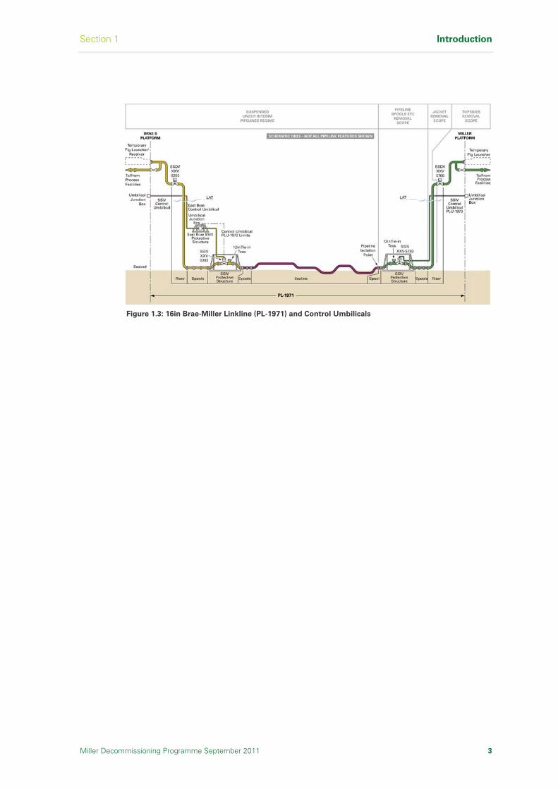
The Miller pipelines, shown in Figures 1.1 to 1.3, are suspended under the Disused Pipelines Notification (Interim Pipelines Regime) [Ref 5] and are not part of this Decommissioning Programme. However, to facilitate removal of the Miller platform, certain pipeline elements are to be removed at the Miller platform end and returned to shore for reuse, recycle or disposal.
Figure 1.1: 30in Gas Export Pipeline (PL-720/PL-833) and Control Umbilical
Figure 1.2: 18in Oil Export Pipeline (PL-722)
Section 1 Introduction
Miller Decommissioning Programme September 2011 3
Figure 1.3: 16in Brae-Miller Linkline (PL-1971) and Control Umbilicals

Introduction Section 1
4 Miller Decommissioning Programme September 2011
I n t e n t i o n a l l y L e f t B l a n k

Section 2 Executive Summary
Miller Decommissioning Programme September 2011 5
2 Executive Summary
The Miller Decommissioning Programme was complied by BP on behalf of
the Miller Section 29 Notice Holders and is submitted for approval in
accordance with the Petroleum Act (1998) Section 29.
2.1 Introduction
The decommissioning of disused offshore Installations is governed under UK law by the Petroleum Act 1998 [Ref 1], as amended by the Energy Act 2008 [Ref 2]. The Decommissioning Programme is set out in accordance with the Department of Energy and Climate Change (DECC) Guidance Notes [Ref 3].
The Miller Field, shown in Figure 2.1, lies in blocks 16/7b and 16/8b in the Central North Sea and was discovered by BP and Conoco in 1982/1983. The Field is located 230km north-east of St Fergus in water depths of approximately 103m.
Figure 2.1: Miller Field Location
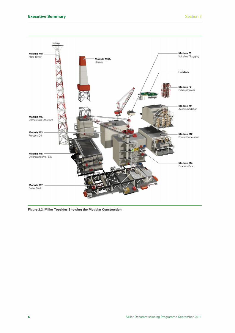
The Miller platform, shown in Figure 2.2, is an integrated oil and gas drilling, production, processing and accommodation platform installed in 1991. The topsides consist of a Module Support Frame (MSF) supporting a number of modules, with an installed weight of approximately 28,732Te [Ref 6]. The topsides are supported by an eight-legged steel jacket, shown in Figure 2.3, weighing approximately 18,584Te [Ref 6].
Executive Summary Section 2
6 Miller Decommissioning Programme September 2011
Figure 2.2: Miller Topsides Showing the Modular Construction

Section 2 Executive Summary
Miller Decommissioning Programme September 2011 7
Figure 2.3: Miller Jacket

Executive Summary Section 2
8 Miller Decommissioning Programme September 2011
The platform, installed in 1991, is operated by BP Exploration (Alpha) Limited on behalf of the Platform Section 29 Notice Holders (refer to Table 2.1) and produced from June 1992 until formal Cessation of Production as approved by DECC in September 2007 [Ref 7].
BP Exploration (Alpha) Ltd.
ConocoPhillips (U.K.) Ltd.
Shell UK Ltd.
Section 29 Notice Holders
BP Exploration Operating Company Ltd.
Table 2.1: Miller Platform Section 29 Notice Holders
2.2 Recommendations
The following recommendations are based on legal requirements, studies, the Independent Review Consultant (IRC) review [Ref 8] and stakeholder participation.
Recommendations
The wells are plugged and abandoned. Removed items are returned to shore for reuse, recycling or disposal
The topsides modules are removed and returned to shore for reuse, recycling or disposal
The jacket is removed down to the top of the jacket footings and returned to shore for reuse, recycling or disposal. The jacket footings and the drilling template are left in place
The pipelines are flushed clear of hydrocarbons and left in situ for possible future use. Pipeline spools, umbilicals, SSIVs and structures associated with platform removal activity are removed and returned to shore for reuse, recycling or disposal
The cuttings pile is left in situ to degrade and to allow the seabed to recover naturally
Following completion of decommissioning work a seabed survey is undertaken to identify oilfield related debris within the platform 500m zone, and a 200m corridor along each pipeline up to 100m outside the pipeline isolation point. All items of oilfield debris identified will be categorised and, in consultation with DECC, a management plan will be agreed
These recommendations are further discussed in Section 2.5.
Section 2 Executive Summary
Miller Decommissioning Programme September 2011 9
2.3 Legal Requirements
The decommissioning of disused offshore Installations is governed under UK law by the Petroleum Act 1998 [Ref 1], as amended by the Energy Act 2008 [Ref 2].
Under the terms of OSPAR Decision 98/3 [Ref 4], which entered into force on 9th February 1999, there is a general prohibition on the dumping and leaving wholly or partly in place of offshore Installations. The topsides modules of all Installations must be returned to shore. All platforms with a jacket weight less than 10,000Te must be completely removed for re-use, recycling or final disposal on land. The Decision recognises that there may be difficulty in removing the 'footings' of large steel jackets weighing more than 10,000Te and installed before 9th February 1999. As a result there is a provision for derogation from the OSPAR requirement for such Installations. It is a requirement that these cases should be considered individually to assess whether it may be appropriate to leave the footings of large steel Installations in place. Nevertheless, there is a presumption that they will be removed entirely and exceptions to that rule will be granted only if the assessment and consultation procedure, which forms part of OSPAR Decision 98/3, demonstrates that there are significant reasons why an alternative disposal option is preferable to re-use or recycling or final disposal on land.
The DECC Guidance Notes [Ref 3], under the Petroleum Act 1998 [Ref 1], incorporates the UK’s international obligations relating to the disposal of offshore Installations which fall under the OSPAR conventions.
2.4 Principles Used to Assess Decommissioning Options
The Miller Section 29 Notice Holders used a thorough screening and
evaluation process against the criteria set out in the DECC Decommissioning
Guidance Notes [Ref 3] to arrive at the recommended options for
decommissioning the Miller facilities. The process was designed to assess the
technical, safety, environmental, financial and societal impacts for all the
decommissioning options considered.
The DECC Guidance Notes [Ref 3] state that the decommissioning programme should be consistent with international obligations and take into consideration:
The precautionary principle
Best available techniques and best environmental practice
Waste hierarchy principles
Other users of the sea
Health and safety law
Proportionality
Cost effectiveness
These form the basis of the principles used to assess the decommissioning options.
Executive Summary Section 2
10 Miller Decommissioning Programme September 2011
2.4.1 Method and Evaluation Process
The Miller Section 29 Notice Holders commissioned a wide range of detailed
studies to fully understand all aspects of the project.
A list of all study references is published in Section 17 of the Decommissioning Programme. In accordance with the DECC Guidance Notes [Ref 3] and to provide consistency to the evaluation of options, the studies were designed under the following key evaluation criteria:
Safety of all personnel involved in the decommissioning activities both offshore and onshore
Environmental impact of all activities at the offshore location and also the onshore dismantling and disposal site
Technical feasibility of implementing the operations
Societal impact on users of the sea, businesses and communities with the potential to be impacted by the decommissioning activity
Economic impacts of the work programme
Each of the studies was scoped to provide information related to one or more of the above evaluation criteria. Each of the studies was implemented by a variety of external contractors, consultants and other specialists and resulted in the decommissioning recommendations presented for Miller. The range of studies completed was categorised as follows:
Studies to identify alternatives to decommissioning, or uses for the platform either in the current location or other locations that align with the intent of the waste hierarchy
Removal studies to evaluate the full removal of the Miller platform and all associated material to achieve a clear seabed
Research and joint industry projects to define and understand areas of decommissioning generally acknowledged as problematic
Comparative assessment studies to describe and compare the alternative options in compliance with the requirements of the OSPAR Decision 98/3 [Ref 4]
Assessment of the cuttings pile for the rate of oil loss and persistence over the area of contaminated seabed against the OSPAR Recommendation 2006/5 [Ref 9] thresholds
2.4.2 Evaluation of Impacts
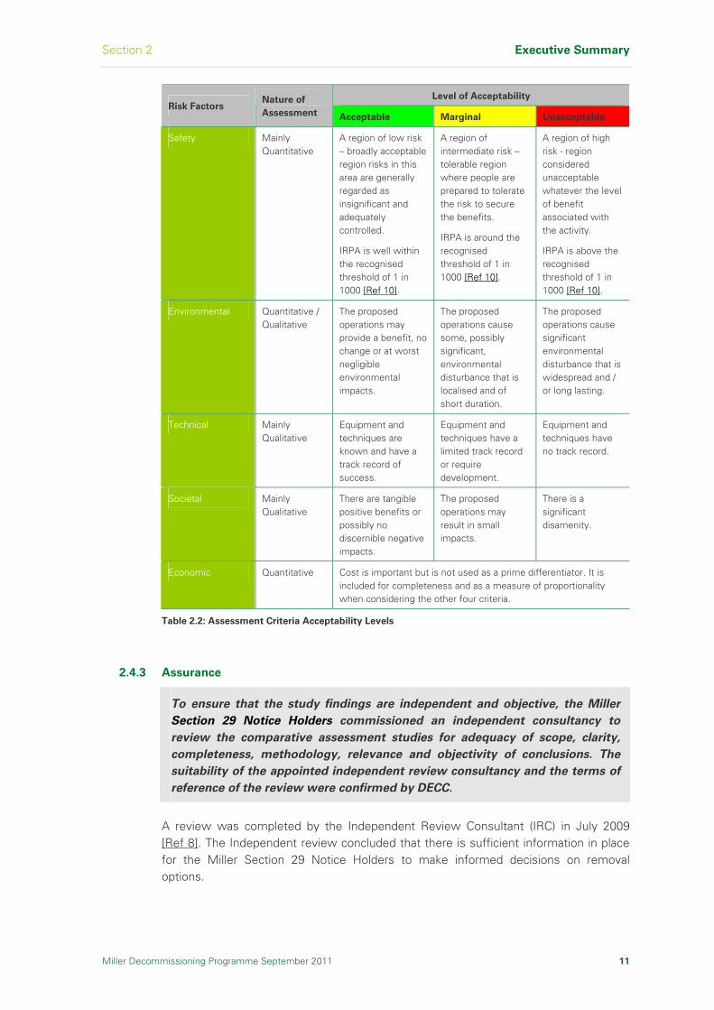
A summary of the criteria and their acceptability levels is shown in Table 2.2.
The evaluations are a combination of qualitative and quantitative impacts. These criteria were used for the evaluation of options for the decommissioning of the jacket footings.
Section 2 Executive Summary
Miller Decommissioning Programme September 2011 11
Level of Acceptability Risk Factors
Nature of
Assessment Acceptable Marginal Unacceptable
Safety Mainly Quantitative
A region of low risk – broadly acceptable region risks in this area are generally regarded as insignificant and adequately controlled.
IRPA is well within the recognised threshold of 1 in 1000 [Ref 10].
A region of intermediate risk – tolerable region where people are prepared to tolerate the risk to secure the benefits.
IRPA is around the recognised threshold of 1 in 1000 [Ref 10].
A region of high risk - region considered unacceptable whatever the level of benefit associated with the activity.
IRPA is above the recognised threshold of 1 in 1000 [Ref 10].
Environmental Quantitative / Qualitative
The proposed operations may provide a benefit, no change or at worst negligible environmental impacts.
The proposed operations cause some, possibly significant, environmental disturbance that is localised and of short duration.
The proposed operations cause significant environmental disturbance that is widespread and / or long lasting.
Technical Mainly Qualitative
Equipment and techniques are known and have a track record of success.
Equipment and techniques have a limited track record or require development.
Equipment and techniques have no track record.
Societal Mainly Qualitative
There are tangible positive benefits or possibly no discernible negative impacts.
The proposed operations may result in small impacts.
There is a significant disamenity.
Economic Quantitative Cost is important but is not used as a prime differentiator. It is included for completeness and as a measure of proportionality when considering the other four criteria.
Table 2.2: Assessment Criteria Acceptability Levels
2.4.3 Assurance
To ensure that the study findings are independent and objective, the Miller
Section 29 Notice Holders commissioned an independent consultancy to
review the comparative assessment studies for adequacy of scope, clarity,
completeness, methodology, relevance and objectivity of conclusions. The
suitability of the appointed independent review consultancy and the terms of
reference of the review were confirmed by DECC.
A review was completed by the Independent Review Consultant (IRC) in July 2009 [Ref 8]. The Independent review concluded that there is sufficient information in place for the Miller Section 29 Notice Holders to make informed decisions on removal options.

Executive Summary Section 2
12 Miller Decommissioning Programme September 2011
2.4.4 External Stakeholder Consultation
The Miller Section 29 Notice Holders invited comments from, and engaged
with, a range interested parties.
A range of organisations and individuals were contacted and invited to register an interest in the Miller Decommissioning consultation process at an early stage in the project.
Several meetings were held with individual organisations and interested parties also received regular updates by e-mail. The Miller Section 29 Notice Holders have established a public website at www.bp.com/miller where information on the project is available.
Public consultation on the proposals contained in the Decommissioning Programme including statutory consultation, was carried out as a result of the submission of the draft Decommissioning Programme. Details of issues raised through this consultation process are documented in Section 11. A consultation on the proposal to leave the jacket footings and drilling template in place was undertaken by the UK Government under the terms of OSPAR Decision 98/3 [Ref 4]. The outcome of this consultation is summarised in Section 11. The public website for information on Miller decommissioning is www.bp.com/miller.
2.5 Decommissioning Options Assessments
2.5.1 Well Abandonment and Conductor Removal
The wells are plugged and abandoned under the Oil & Gas UK (OGUK) Guidelines for the Suspension and Abandonment of Wells [Ref 11].
This required two cement plugs to be installed deep in each well to ensure that the reservoir is completely sealed off. For Miller, cement plugs at 2000m and 500m were also set to isolate upper naturally pressured permeable zones and an environmental cement plug set to isolate the borehole from the surface. The conductors have been removed.
Status
The wells are plugged and abandoned. Removed items have been returned to shore for reuse, recycling or disposal.
2.5.2 Topsides Modules Decommissioning
Existing proven technologies are available to undertake the safe removal and transportation of the topsides modules to an onshore location for reuse, recycling or disposal.
Recommendation
The topsides modules are removed and returned to shore for reuse, recycling or disposal.
Section 2 Executive Summary
Miller Decommissioning Programme September 2011 13
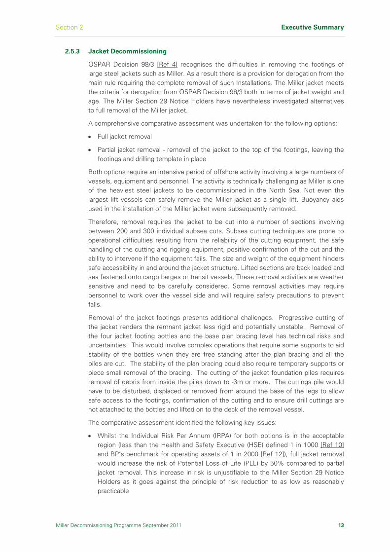
2.5.3 Jacket Decommissioning
OSPAR Decision 98/3 [Ref 4] recognises the difficulties in removing the footings of large steel jackets such as Miller. As a result there is a provision for derogation from the main rule requiring the complete removal of such Installations. The Miller jacket meets the criteria for derogation from OSPAR Decision 98/3 both in terms of jacket weight and age. The Miller Section 29 Notice Holders have nevertheless investigated alternatives to full removal of the Miller jacket.
A comprehensive comparative assessment was undertaken for the following options:
Full jacket removal
Partial jacket removal - removal of the jacket to the top of the footings, leaving the footings and drilling template in place
Both options require an intensive period of offshore activity involving a large numbers of vessels, equipment and personnel. The activity is technically challenging as Miller is one of the heaviest steel jackets to be decommissioned in the North Sea. Not even the largest lift vessels can safely remove the Miller jacket as a single lift. Buoyancy aids used in the installation of the Miller jacket were subsequently removed.
Therefore, removal requires the jacket to be cut into a number of sections involving between 200 and 300 individual subsea cuts. Subsea cutting techniques are prone to operational difficulties resulting from the reliability of the cutting equipment, the safe handling of the cutting and rigging equipment, positive confirmation of the cut and the ability to intervene if the equipment fails. The size and weight of the equipment hinders safe accessibility in and around the jacket structure. Lifted sections are back loaded and sea fastened onto cargo barges or transit vessels. These removal activities are weather sensitive and need to be carefully considered. Some removal activities may require personnel to work over the vessel side and will require safety precautions to prevent falls.
Removal of the jacket footings presents additional challenges. Progressive cutting of the jacket renders the remnant jacket less rigid and potentially unstable. Removal of the four jacket footing bottles and the base plan bracing level has technical risks and uncertainties. This would involve complex operations that require some supports to aid stability of the bottles when they are free standing after the plan bracing and all the piles are cut. The stability of the plan bracing could also require temporary supports or piece small removal of the bracing. The cutting of the jacket foundation piles requires removal of debris from inside the piles down to -3m or more. The cuttings pile would have to be disturbed, displaced or removed from around the base of the legs to allow safe access to the footings, confirmation of the cutting and to ensure drill cuttings are not attached to the bottles and lifted on to the deck of the removal vessel.
The comparative assessment identified the following key issues:
Whilst the Individual Risk Per Annum (IRPA) for both options is in the acceptable region (less than the Health and Safety Executive (HSE) defined 1 in 1000 [Ref 10] and BP’s benchmark for operating assets of 1 in 2000 [Ref 12]), full jacket removal would increase the risk of Potential Loss of Life (PLL) by 50% compared to partial jacket removal. This increase in risk is unjustifiable to the Miller Section 29 Notice Holders as it goes against the principle of risk reduction to as low as reasonably practicable

Executive Summary Section 2
14 Miller Decommissioning Programme September 2011
Whilst both options cause some environmental disturbance that is localised and of short duration, full jacket removal results in a 40% increase in energy consumption and emissions to the atmosphere as compared to partial jacket removal [Ref 13]. This increase in environmental impact is unjustifiable to the Miller Section 29 Notice Holders as it goes against the principle of best practicable environmental option
Full jacket removal is technically more challenging than partial jacket removal. Equipment and techniques required to remove the footings of large steel jackets do not have a demonstrable track record. The probability of major project failure (defined by a cost increase of 15 to 50% and a schedule increase of three to six months) increases by 130% for full jacket removal compared to partial jacket removal. This is unacceptable to the Miller Section 29 Notice Holders
Partial jacket removal creates a long term and persistent risk to fishermen from the snagging of fishing gear. The increase in Individual Risk per Annum (IRPA) directly attributable to the Miller footings is very low and of the order of 7.5 x 10⁻⁸ [Ref 14]
Partial removal of the Miller jacket creates a physical obstruction on the seabed, which is a snagging hazard for the fishing industry. This requires a range of mitigation measures to ensure this area is clearly marked as an obstruction. The obstructed area is extremely small in comparison to the overall size of the fishing grounds, having a footprint less than 0.01km2. The risk to fishermen is proportionately lower than the additional decommissioning risks to remove the footings. Based on Implied Cost of Averting a Fatality (ICAF) principles, the additional cost to remove the footings cannot be justified, compared to the societal risk saved [Ref 14]. The cost to remove the footings is disproportionate to the benefit. It has been identified that through supporting work with the UK Fisheries Offshore Oil & Gas Legacy Trust Fund Limited (FLTC), that there are other effective means of reducing risk to all fishermen (not just those engaged in fishing in the vicinity of Miller) with the realisation of vastly higher cost benefits than by the removal of the Miller footings. Miller is not a major fishing ground; the average fishing effort in the Miller area (ICES rectangle 46F1 of approximately 900nm2) from 2000 to 2007 was 73 vessel days per annum [Ref 15]
The cost of full jacket removal is approximately 37% higher than for partial jacket removal
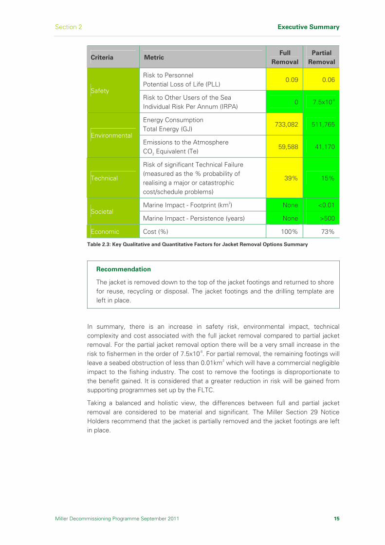
The comparative assessment results are listed in Table 2.3.
Section 2 Executive Summary
Miller Decommissioning Programme September 2011 15
Criteria Metric Full
Removal
Partial
Removal
Risk to Personnel Potential Loss of Life (PLL)
0.09 0.06
Safety Risk to Other Users of the Sea Individual Risk Per Annum (IRPA)
0 7.5x10⁻⁸
Energy Consumption Total Energy (GJ)
733,082 511,765
Environmental Emissions to the Atmosphere CO2 Equivalent (Te)
59,588 41,170
Technical
Risk of significant Technical Failure (measured as the % probability of realising a major or catastrophic cost/schedule problems)
39% 15%
Marine Impact - Footprint (km2) None <0.01 Societal
Marine Impact - Persistence (years) None >500
Economic Cost (%) 100% 73%
Table 2.3: Key Qualitative and Quantitative Factors for Jacket Removal Options Summary
Recommendation
The jacket is removed down to the top of the jacket footings and returned to shore for reuse, recycling or disposal. The jacket footings and the drilling template are left in place.
In summary, there is an increase in safety risk, environmental impact, technical complexity and cost associated with the full jacket removal compared to partial jacket removal. For the partial jacket removal option there will be a very small increase in the risk to fishermen in the order of 7.5x10⁻⁸. For partial removal, the remaining footings will leave a seabed obstruction of less than 0.01km2 which will have a commercial negligible impact to the fishing industry. The cost to remove the footings is disproportionate to the benefit gained. It is considered that a greater reduction in risk will be gained from supporting programmes set up by the FLTC.
Taking a balanced and holistic view, the differences between full and partial jacket removal are considered to be material and significant. The Miller Section 29 Notice Holders recommend that the jacket is partially removed and the jacket footings are left in place.

Executive Summary Section 2
16 Miller Decommissioning Programme September 2011
2.5.4 Pipelines
Miller Pipelines
The Miller pipelines are suspended under the Disused Pipelines Notification (Interim Pipelines Regime) [Ref 5] for 10 years from approval for Cessation of Production, so that re-use opportunities can be explored. They are not part of this Decommissioning Programme submission. The Interim Pipeline Regime is intended to ensure that out of use pipelines do not pose a risk to other users of the sea or to the Environment and that they are covered by an appropriate survey and maintenance regime until a decommissioning programme for the pipelines is approved.
All Miller pipelines have been flushed clear of hydrocarbons and are left in situ for possible future use. Blind flanges are fitted at pipeline isolation points to seal the pipelines as indicated in Section 1, Figures 1.1 to 1.3.
Pipeline Spools, Umbilicals, Subsea Isolation Valves (SSIV) and Associated Items
at Miller
To facilitate removal of the platform, certain pipeline items are to be removed at the Miller platform end and returned to shore for reuse, recycling or disposal. Items to be removed are as follows:
30in gas export pipeline (PL-720) - pipeline closing spools, SSIV and associated control umbilical
18in oil export pipeline (PL-722) - pipeline closing spools
16in Brae-Miller Linkline (PL-1971) - pipeline closing spools, SSIV and associated control umbilical (PLU-1973)
Recommendation
The pipelines are flushed clear of hydrocarbons and left in situ for possible future use. Pipeline spools, umbilicals, SSIVs and structures associated with platform removal activity are removed and returned to shore for reuse, recycling or disposal.
2.5.5 Cuttings Pile
The Miller cuttings pile was assessed against the OSPAR Management Regime for Offshore Cuttings Piles Recommendation 2006/5 [Ref 9] criteria for rate of oil loss to the water column and persistence over the area of seabed contaminated. The results shown in Table 2.4 indicate values significantly below the OSPAR Regime Stage 1 [Ref 9] thresholds. Therefore, the management strategy is to leave the cuttings pile in situ to degrade and to allow the seabed to recover naturally.

Section 2 Executive Summary
Miller Decommissioning Programme September 2011 17
Metric OSPAR Threshold Miller Value
Rate of oil loss (Te/year) 10 1.81
Persistence over the area of contaminated seabed (Km2/year)
500 27.0
Table 2.4: Rate of Oil Loss and Persistence over the Area of Contaminated Seabed – OSPAR 2006/5
Thresholds and Miller Values
Recommendation
The cuttings pile is left in situ to degrade and to allow the seabed to recover naturally.
2.5.6 Seabed Debris and other Items
Following the completion of the decommissioning work, seabed surveys for oilfield debris will be carried out at the following locations:
The platform 500m zone
The pipelines local to the platform within a 200m corridor along each pipeline up to 100m outside the pipeline isolation point
The objective of the surveys and any remedial actions, is to reduce risk for other users of the sea.
Seabed debris located will be identified and catalogued, and an assessment made in discussion with DECC to agree the required remedial action. Following the remedial action agreed above, verification of seabed clearance by an independent organisation, in agreement with DECC will be carried out.
Recommendation
Following completion of decommissioning work a seabed survey will be undertaken to identify oilfield related debris within the platform 500m zone, and a 200m corridor along each pipeline up to 100m outside the pipeline isolation point. All items of oilfield debris identified will be categorised and, in consultation with DECC, a management plan will be agreed.
2.5.7 Onshore Treatment and Disposal of Materials
For the onshore treatment and disposal of Miller material, the waste hierarchy will be applied, in that material is reused and recycled wherever possible in preference to disposal. It is anticipated that up to 97% of the recovered material will be reused or recycled, and contractual arrangements and other incentives will be put in place to ensure that this figure is maximised.
All waste materials will be transferred, treated or disposed of by licensed contractors at licensed sites with all the necessary permits, licences and consents. Throughout these activities duty of care will be exercised through an appropriate assurance process.
Executive Summary Section 2
18 Miller Decommissioning Programme September 2011
On completion, the quantities of material, reused, recycled and disposed, and the sites and methods used to dispose of hazardous waste will be compiled for reporting.
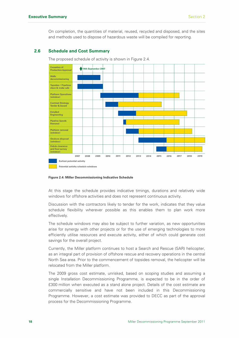
2.6 Schedule and Cost Summary
The proposed schedule of activity is shown in Figure 2.4.
Figure 2.4: Miller Decommissioning Indicative Schedule
At this stage the schedule provides indicative timings, durations and relatively wide windows for offshore activities and does not represent continuous activity.
Discussion with the contractors likely to tender for the work, indicates that they value schedule flexibility wherever possible as this enables them to plan work more effectively.
The schedule windows may also be subject to further variation, as new opportunities arise for synergy with other projects or for the use of emerging technologies to more efficiently utilise resources and execute activity, either of which could generate cost savings for the overall project.
Currently, the Miller platform continues to host a Search and Rescue (SAR) helicopter, as an integral part of provision of offshore rescue and recovery operations in the central North Sea area. Prior to the commencement of topsides removal, the helicopter will be relocated from the Miller platform.
The 2009 gross cost estimate, unrisked, based on scoping studies and assuming a single Installation Decommissioning Programme, is expected to be in the order of £300 million when executed as a stand alone project. Details of the cost estimate are commercially sensitive and have not been included in this Decommissioning Programme. However, a cost estimate was provided to DECC as part of the approval process for the Decommissioning Programme.

Section 2 Executive Summary
Miller Decommissioning Programme September 2011 19
2.7 Legacy Activities
Lessons learned from planning and implementing the Miller Decommissioning Programme will be used to enhance the industry’s technical capability for future decommissioning challenges. In the meantime, the Miller Section 29 Notice Holders will continue to support research into large steel jacket removal technology in collaboration with other operators and major contractors.
The Miller Section 29 Notice Holders will monitor future discussions and decisions under the OSPAR framework for their relevance to the management of the Miller cuttings pile.
Should the Miller Section 29 Notice Holders or reports from other stakeholders identify concerns with equipment or structures left on the seabed, then the Miller Section 29 Notice Holders will mobilise a team. The team will gather further information to assess the concern and then prepare the comparative assessment study of all the options. If necessary, following the comparative assessment study, a revised Decommissioning Programme would be prepared for the appraisal of the relevant authorities prior to commencement of any remedial work.

Executive Summary Section 2
20 Miller Decommissioning Programme September 2011
I n t e n t i o n a l l y L e f t B l a n k

Section 3 Background Information
Miller Decommissioning Programme September 2011 21
3 Background Information
This section provides a history of the Miller Field, and describes the
pipelines, adjacent facilities and commercial, physical, meteorological and
oceanographic conditions.
3.1 Miller Field Development
The Miller Field lies in blocks 16/7b and 16/8b in the Central North Sea and was discovered by BP and Conoco in 1982/1983. The Field is located 230km north-east of St Fergus in water depths of approximately 103m.
Recoverable reserves from the Field were originally estimated to be in excess of 300MMstbd (million stock tank barrels per day) of oil and associated gas. Production started in 1992, however by 2007 the Field had declined and was producing less than 10Mstbd (thousand stock tank barrels per day).
Methods used to extract as much hydrocarbons as possible from the wells included seawater injection (where water is pumped into the edges of the reservoir to force the oil towards the drilling area) and gas injection (where gas is pumped into the reservoir to increase the pressure and so force out more hydrocarbon). In 1997, as the wells lost further pressure, seawater injection was alternated with gas injection.
Formal Cessation of Production was approved by DECC in September 2007 [Ref 7].
3.2 Pipelines
The 18in oil export pipeline (PL-722) transported processed crude oil 7.5km from the Miller platform to the Brae Alpha (A) platform. At Brae A, the oil was comingled with Brae and Heimdal oil and transported by the 30in pipeline (PL-064) to the Forties Charlie platform and onward through the BP Forties Pipeline System (FPS) 36in pipeline (PL-721) to Cruden Bay.
The 30in gas export pipeline (PL-720) transported processed gas 240km from the Miller platform to the St Fergus Terminal Miller Reception Facilities (MRF). At the MRF, the gas pressure was reduced and temperature increased suitable for the entry requirements of landline transportation systems.
In 2003, BP extended the Miller Enhanced Oil Recovery (EOR) scheme with the installation of the 16in Brae-Miller Linkline (PL-1971) between the Brae Bravo (B) and Miller platforms. Predominately used to transport gas 9.5km from Brae B to Miller to be used as gas injection into the Miller reservoir, the Linkline could be configured to flow in either direction.
The pipelines associated with Miller are shown in Figure 3.1.

Background Information Section 3
22 Miller Decommissioning Programme September 2011
3.3 Adjacent Facilities
As shown in Figure 3.1, the three closest platforms to Miller are:
Brae A, located 7.5km west
Brae B, located 9.5km north-west
East Brae, located 18.8km north
Figure 3.1: Adjacent Facilities and Pipelines

Section 3 Background Information
Miller Decommissioning Programme September 2011 23
3.4 Physical, Meteorological and Oceanographic Conditions
Table 3.1 summarises information about the physical, meteorological and oceanographic conditions at the Miller platform and immediate area.
Aspect Information
Platform location 58o43’19.70”N, 01o24’07.40”E
Seabed sediments Dense sand to a depth of 1.5m
Water depth 102.40±0.1m LAT
Maximum tidal range 1.9m
Nearest land St. Fergus, Scotland, 230km south-south-west
Nearest platform Brae ‘A’, 7km west
Distance to median line Median line with Norway is 7km east
Waves 100 years
Significant wave height 14.3m
Maximum wave height 26.2m (trough to peak crest)
Winds (maximum) 100 years
1 minute mean wind speed 10m above LAT 42.0m/sec
3 second gust of wind 10m above LAT 47.3m/sec
Currents 100 years
Maximum surface speed 0.84m/sec
Maximum seabed speed 0.43m/sec
Temperatures Minimum Maximum
Air -6oC +25oC
Sea surface 0oC +14oC
Seabed +6oC +7oC
Table 3.1: Physical, Meteorological and Oceanographic Conditions
3.5 Commercial Fisheries
3.5.1 General
BP commissioned a report to summarise the current commercial fishing baseline within the area of the Miller platform [Ref 15] which lies in ICES statistical rectangle 46F1, ICES sub-area Iva, as shown in Figure 3.2.

Background Information Section 3
24 Miller Decommissioning Programme September 2011
Figure 3.2: Miller Platform Location in Relation to ICES Rectangles [Ref 15]
There is no single data set which can precisely establish the levels of commercial fishing within a small discrete sea area. Therefore, a number of different information sources were used, including the Marine Fisheries Agency (MFA) statistics, surveillance sightings and satellite tracking information, and consultation with north-east based fishermen with experience of fishing the general Miller area. The purpose of this consultation was to obtain details of operating patterns and practices, vessel and gear specifications and the opinions of skippers on interfaces between commercial fishing and oil and gas subsea structures.
3.5.2 Fishing Methods
The five main methods of UK commercial fishing operating in the Miller area are seine netting (either single boat or a pair of boats), twin-rigged trawling, pelagic trawling and purse seining. The area has traditionally been fished by mainly single boat seine netting, although a significant number of seiners are now engaged in pair-seining.
3.5.3 Landings Weights and Values
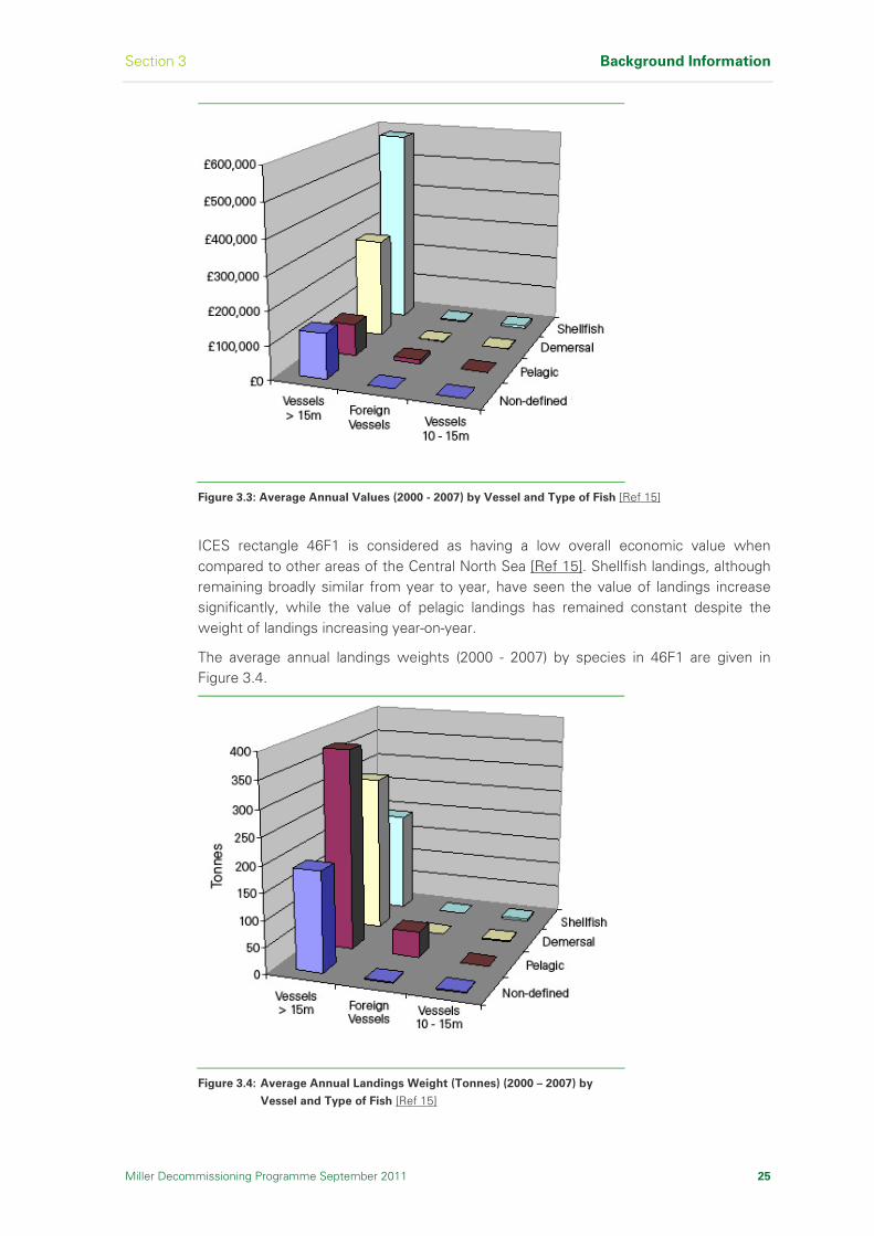
The average annual value of the landings from 46F1 are given in Figure 3.3.
Nephrops are the most important species by landings value with an average annual value of £590,059. The second most valuable catch is Haddock with a value of £181,595. The majority of these landings, irrespective of nationality, are from vessels over 15m length.
Section 3 Background Information
Miller Decommissioning Programme September 2011 25
Figure 3.3: Average Annual Values (2000 - 2007) by Vessel and Type of Fish [Ref 15]
ICES rectangle 46F1 is considered as having a low overall economic value when compared to other areas of the Central North Sea [Ref 15]. Shellfish landings, although remaining broadly similar from year to year, have seen the value of landings increase significantly, while the value of pelagic landings has remained constant despite the weight of landings increasing year-on-year.
The average annual landings weights (2000 - 2007) by species in 46F1 are given in Figure 3.4.
Figure 3.4: Average Annual Landings Weight (Tonnes) (2000 – 2007) by
Vessel and Type of Fish [Ref 15]

Background Information Section 3
26 Miller Decommissioning Programme September 2011
The highest landed weight was 339 tonnes for herring, 85.5% of which was landed by UK vessels and 14.5% by foreign vessels.
The second highest landings recorded weight was for haddock followed by Nephrops. This illustrates the low unit value of herring in comparison to that of Nephrops.
3.5.4 Fishing Effort
In comparison to the average annual fishing effort by UK and foreign vessels landing in UK ports, the effort in rectangle 46F1 is moderate to the majority of other rectangles in sub-area IVa.
Figure 3.5 gives the days fished per annum in rectangle 46F1 between 2000 and 2007, which suggest a pattern of declining effort with relatively low levels occurring in 2007. The clear majority of the recorded effort has been from vessels over 15m length.
Figure 3.5: Annual Fishing Effort (Days Fished between 2000 – 2007) by Vessel Category [Ref 15]
The annual effort by fishing method is illustrated in Figure 3.6. The highest levels of effort have been from the category defined as ‘otter trawls’. However, the Scottish Fishermen’s Federation (SFF) report suggests that as most of the Scottish east coast operate twin-rig trawls, it is probable that the majority of the effort recorded in the ‘otter trawls-bottom’ category was in fact from twin-rig otter trawlers.
The seasonality of effort within 46F1 is illustrated by Figure 3.7, which gives the average days fishing per month (2000 – 2007) by method and shows moderately lower levels of activity in mid-summer and mid-winter for most methods.
3.5.5 Vessel Tracking
Satellite tracking of UK fishing vessels in sub-area IVA, as shown in Figure 3.8, confirms that the Miller platform is located within an area where the levels of fishing activity are significantly lower than in adjacent areas.
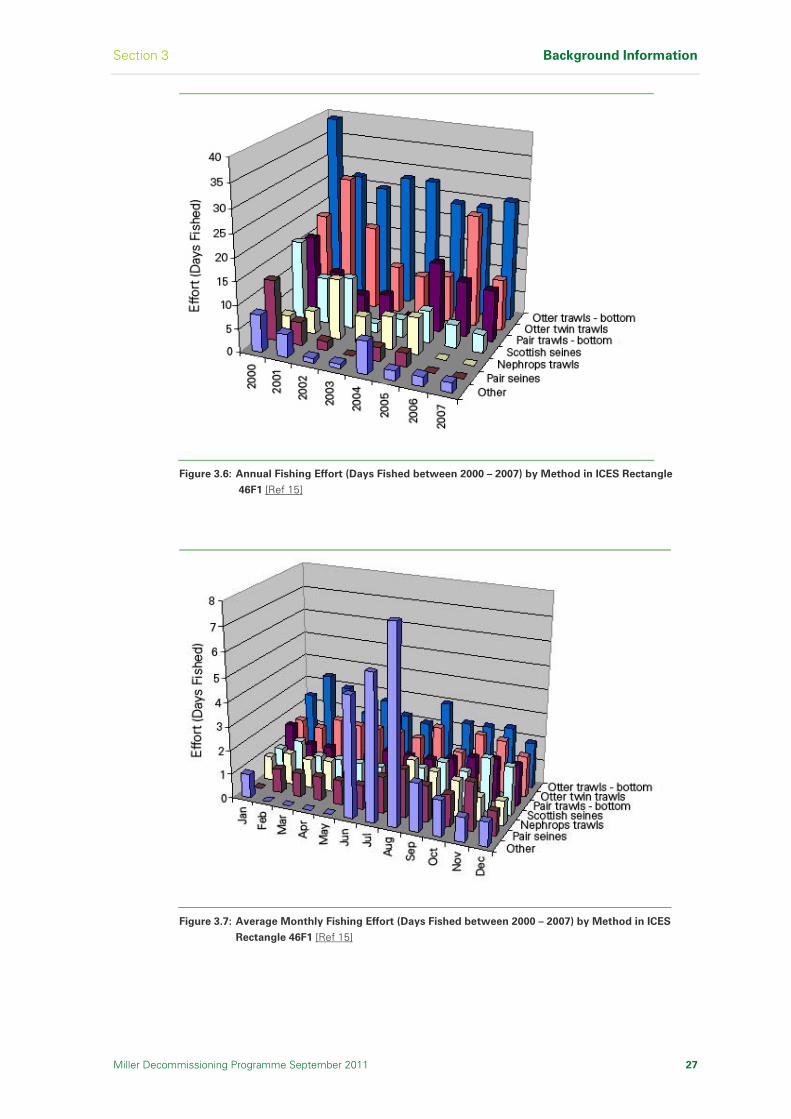
Section 3 Background Information
Miller Decommissioning Programme September 2011 27
Figure 3.6: Annual Fishing Effort (Days Fished between 2000 – 2007) by Method in ICES Rectangle
46F1 [Ref 15]
Figure 3.7: Average Monthly Fishing Effort (Days Fished between 2000 – 2007) by Method in ICES
Rectangle 46F1 [Ref 15]
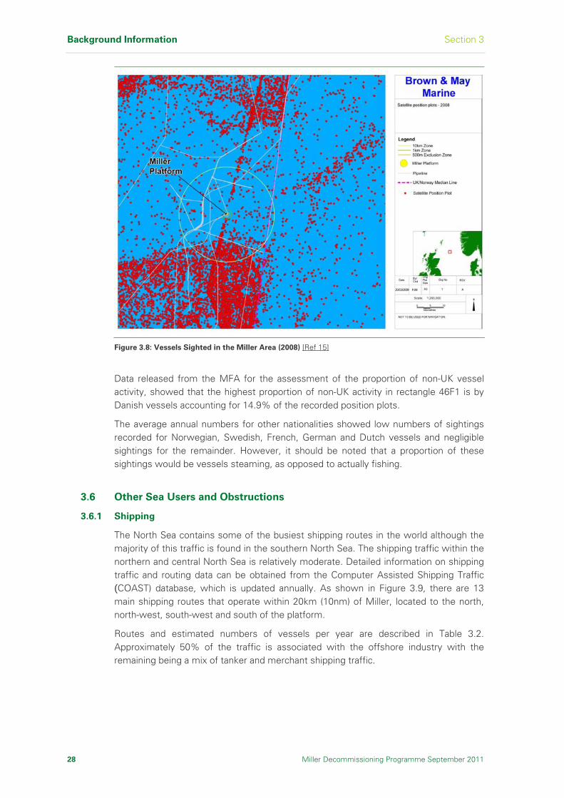
Background Information Section 3
28 Miller Decommissioning Programme September 2011
Figure 3.8: Vessels Sighted in the Miller Area (2008) [Ref 15]
Data released from the MFA for the assessment of the proportion of non-UK vessel activity, showed that the highest proportion of non-UK activity in rectangle 46F1 is by Danish vessels accounting for 14.9% of the recorded position plots.
The average annual numbers for other nationalities showed low numbers of sightings recorded for Norwegian, Swedish, French, German and Dutch vessels and negligible sightings for the remainder. However, it should be noted that a proportion of these sightings would be vessels steaming, as opposed to actually fishing.
3.6 Other Sea Users and Obstructions
3.6.1 Shipping
The North Sea contains some of the busiest shipping routes in the world although the majority of this traffic is found in the southern North Sea. The shipping traffic within the northern and central North Sea is relatively moderate. Detailed information on shipping traffic and routing data can be obtained from the Computer Assisted Shipping Traffic (COAST) database, which is updated annually. As shown in Figure 3.9, there are 13 main shipping routes that operate within 20km (10nm) of Miller, located to the north, north-west, south-west and south of the platform.
Routes and estimated numbers of vessels per year are described in Table 3.2. Approximately 50% of the traffic is associated with the offshore industry with the remaining being a mix of tanker and merchant shipping traffic.
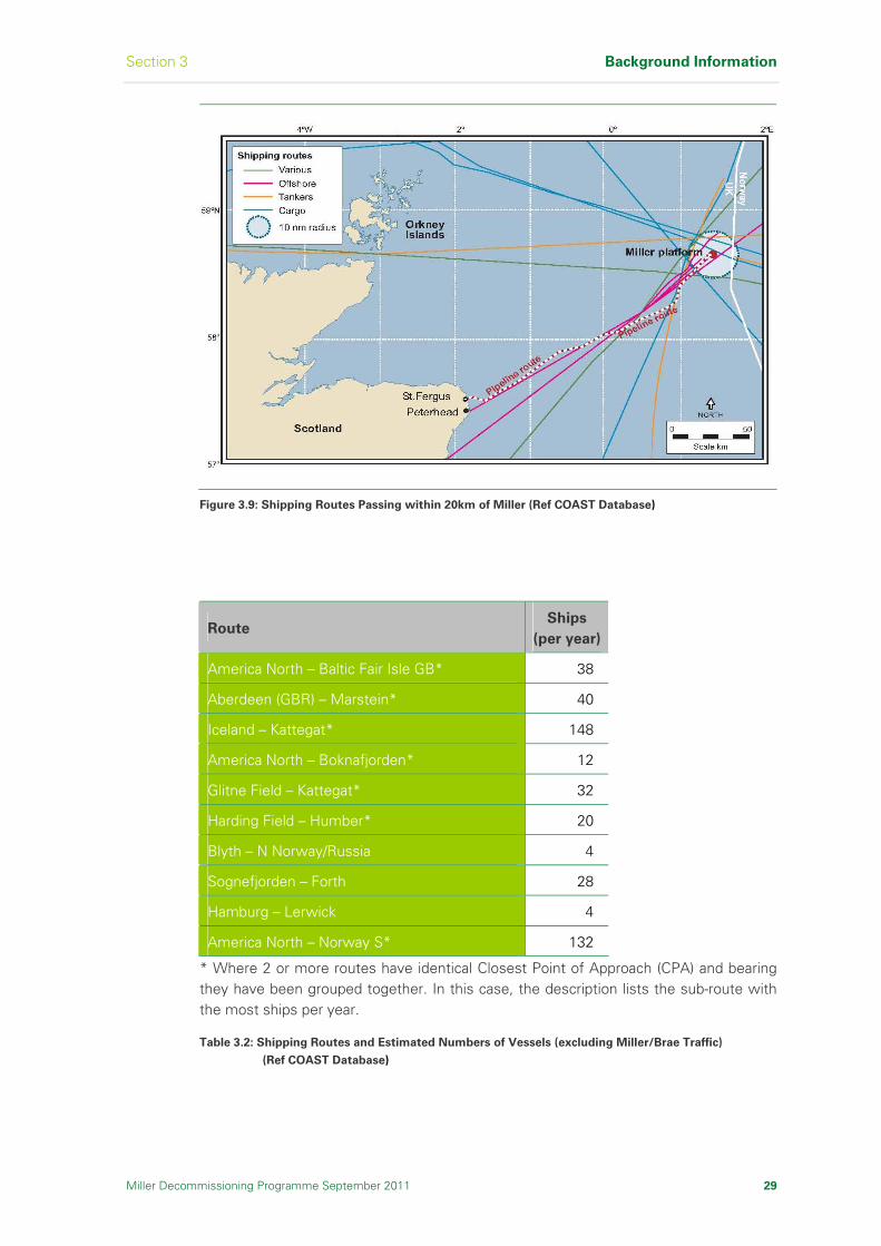
Section 3 Background Information
Miller Decommissioning Programme September 2011 29
Figure 3.9: Shipping Routes Passing within 20km of Miller (Ref COAST Database)
Route Ships
(per year)
America North – Baltic Fair Isle GB* 38
Aberdeen (GBR) – Marstein* 40
Iceland – Kattegat* 148
America North – Boknafjorden* 12
Glitne Field – Kattegat* 32
Harding Field – Humber* 20
Blyth – N Norway/Russia 4
Sognefjorden – Forth 28
Hamburg – Lerwick 4
America North – Norway S* 132
* Where 2 or more routes have identical Closest Point of Approach (CPA) and bearing they have been grouped together. In this case, the description lists the sub-route with the most ships per year.
Table 3.2: Shipping Routes and Estimated Numbers of Vessels (excluding Miller/Brae Traffic)
(Ref COAST Database)

Background Information Section 3
30 Miller Decommissioning Programme September 2011
3.6.2 Wrecks
There are no charted shipwrecks in the immediate vicinity (200m radius) of Miller.
3.6.3 Military Activities
No routine military activities are known to occur in the vicinity of Miller.
3.6.4 Submarine Cables
There are no known submarine telecommunications or power cables in the vicinity of Miller.
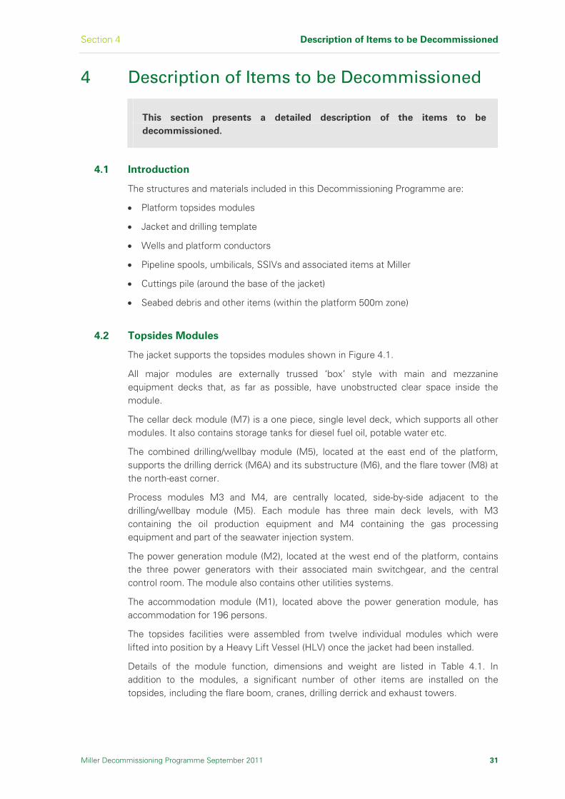
Section 4 Description of Items to be Decommissioned
Miller Decommissioning Programme September 2011 31
4 Description of Items to be Decommissioned
This section presents a detailed description of the items to be
decommissioned.
4.1 Introduction
The structures and materials included in this Decommissioning Programme are:
Platform topsides modules
Jacket and drilling template
Wells and platform conductors
Pipeline spools, umbilicals, SSIVs and associated items at Miller
Cuttings pile (around the base of the jacket)
Seabed debris and other items (within the platform 500m zone)
4.2 Topsides Modules
The jacket supports the topsides modules shown in Figure 4.1.
All major modules are externally trussed ‘box’ style with main and mezzanine equipment decks that, as far as possible, have unobstructed clear space inside the module.
The cellar deck module (M7) is a one piece, single level deck, which supports all other modules. It also contains storage tanks for diesel fuel oil, potable water etc.
The combined drilling/wellbay module (M5), located at the east end of the platform, supports the drilling derrick (M6A) and its substructure (M6), and the flare tower (M8) at the north-east corner.
Process modules M3 and M4, are centrally located, side-by-side adjacent to the drilling/wellbay module (M5). Each module has three main deck levels, with M3 containing the oil production equipment and M4 containing the gas processing equipment and part of the seawater injection system.
The power generation module (M2), located at the west end of the platform, contains the three power generators with their associated main switchgear, and the central control room. The module also contains other utilities systems.
The accommodation module (M1), located above the power generation module, has accommodation for 196 persons.
The topsides facilities were assembled from twelve individual modules which were lifted into position by a Heavy Lift Vessel (HLV) once the jacket had been installed.
Details of the module function, dimensions and weight are listed in Table 4.1. In addition to the modules, a significant number of other items are installed on the topsides, including the flare boom, cranes, drilling derrick and exhaust towers.
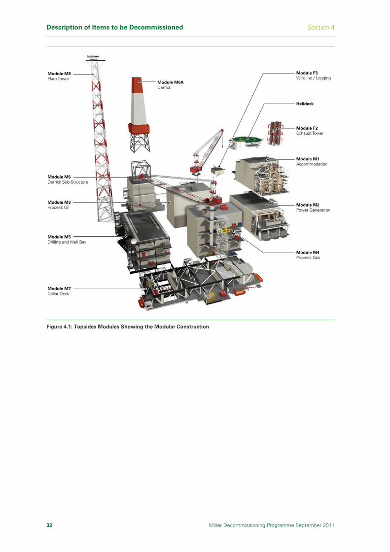
Description of Items to be Decommissioned Section 4
32 Miller Decommissioning Programme September 2011
Figure 4.1: Topsides Modules Showing the Modular Construction

Section 4 Description of Items to be Decommissioned
Miller Decommissioning Programme September 2011 33
Module
Reference Description
Dimensions (m)
(L x W x H)
Weight
(Te)
M1 Accommodation 24 x 30 x 24 2,258
M2 Power generation 45 x 24 x 18.5 3,949
M3 Process (Separation) 32 x 20 x 29.94 4,246
M4 Process (Gas compression) 32 x 20 x 29.59 4,088
M5 Drilling/Wellbay 51 x 21.5 x 20.15 4,899
M6 Drilling (Substructure and skidbase) 26 x 23 x 30 1,336
M6A Drilling derrick 20 x 20 x 46 212
M7 Cellar deck 71 x 30 x 11.5 6,674
M8 Flare tower 12 x 12 x 113 391
H0 Helideck 31 x 30 x 4 154
F2 Exhaust tower 24 x 8.8 x 37 438
F3 Wireline logging unit 8.2 x 8.2 x 5.0 87
Total estimated dry weight of topsides modules 28,732
Note: All weights are indicative. Refer to the Platform Materials Inventory [Ref 6] for latest information.
Table 4.1: Miller Topsides Modules Size and Weight
4.3 Jacket and Drilling Template
4.3.1 Jacket
As shown in Figure 4.2 and Section 2 Figure 2.3, the eight legged, all welded steel tubular jacket is supported by horizontal and diagonal bracings. The bracings provide overall structural strength with the inner legs stiffened by diagonal bracings between the horizontal bracings. The jacket was built onshore and transported to its present location by barge, where it was launched, positioned over the drilling template, and fixed to the seabed using steel piles.
Each of the four corner legs has five 96in diameter vertical piles securing it to the seabed. At the base of the jacket the piles enter pile clusters, formed by 15.49m long pile sleeves and are driven into the seabed to a depth of 55m below the mudline. The pile sleeves are fixed to the lower part of each leg, and the connection between the piles and the sleeves is made by cementing (‘grouting’) them in place. These corner legs and the associated piles and pile sleeves are referred to as ‘bottles’, and the section of the jacket from the seabed to the top of the bottles and piles, including all the bracing and other equipment, is referred to collectively as the ‘footings’ (see Figures 4.2 and 4.3).
The footings are approximately 20m above the seabed and the total weight, including piles and grout above the -3m cut off level below the seabed, is approximately 6461 tonnes [Ref 16, [Ref 17]. A combined system of sacrificial anodes made from aluminium and an aluminium-zinc alloy, and an epoxy coal tar coating protects the jacket and other underwater steel components against corrosion.
Details of the jacket items size and weight are listed in Table 4.2.

Description of Items to be Decommissioned Section 4
34 Miller Decommissioning Programme September 2011
Figure 4.2: Jacket Main Components

Section 4 Description of Items to be Decommissioned
Miller Decommissioning Programme September 2011 35
Figure 4.3: Relative Size of Jacket Footings to Person

Description of Items to be Decommissioned Section 4
36 Miller Decommissioning Programme September 2011
Item Number Dimensions Total Dry Weight
in Air (Te)
Jacket 1 122.5m high(1) 16,927
Anodes 920 Variable according to service 307(4)
Piles(2) 20 70m x 2.438m (96in dia) 1,746(3)(4)
J tubes 4 8in nominal diameter (4)
Risers 9 8in to 30in nominal diameter (4)
Caissons(5) 14 0.273m – 1.2m diameter (4)
Marine Growth N/A N/A 1,657
Total 18,584
Notes:
(1) The base is 71m x 55m, tapering to 71m x 30m at the top. (2) There are five 96in diameter piles arranged in clusters at each corner, and they penetrate 55m
into the seabed. (3) The total weight of piles is 6,136 tonnes. The weight secured to the jacket above -3 LAT is
1746 tonnes. (4) These items are included in the jacket weight. (5) All weights are indicative. Refer to the Platform Materials Inventory [Ref 6] for latest
information.
Table 4.2: Miller Jacket Items Size and Weight
The jacket design includes facilities caissons (to provide a safe housing for submerged pumps) and drain caissons (to discharge waste at depths such that it will disperse to sea) as listed in Table 4.3.
Number Diameter (m) Function Termination
Depth (m)
1 1.200 Umbilical J-tube -92
3 1.000 Seawater lift -70
1 1.100 Hazardous oily water drain -49
1 0.406 Produced water outfall +8
1 1.100 Seawater dump -16
1 1.200 Firewater lift pump -70
2 1.200 Firewater lift pump -42
1 0.273 Sanitary outfall -15
1 1.000 Drilling cuttings chute -45
1 1.000 Non-hazardous drain -37
1 1.000 Umbilical J-tube -91
Table 4.3: Miller Caissons

Section 4 Description of Items to be Decommissioned
Miller Decommissioning Programme September 2011 37
4.3.2 Drilling Template
A 16-slot drilling template [Ref 18] was installed on the seabed and seven wells drilled prior to installation of the jacket. The T-shaped template is a welded steel structure 12m long, 8m wide and 3.4m high, and weighs (without the weight of the piles 3m below the seabed) approximately 150 tonnes [Ref 19]. It is fixed to the seabed by four 20in diameter driven steel support piles that are attached to the template through tubular sleeves, as shown in Figure 4.4.
Figure 4.4: Miller Drilling Template
Three mudmat levelling jacks were installed to level and support the template prior to and during support pile installation. In addition, two 72in locating piles, guided by template sleeves, were installed as a means of accurately aligning the platform jacket.
4.4 Wells and Platform Conductors
The Miller platform was designed to accommodate 40 wells. Over the life of the Field, 22 operational wells (including new wells and sidetracks) were drilled into the reservoir, with the last well drilled in 2003 [Ref 7]. The wells were drilled using directional drilling, which enabled the entire reservoir to be accessed from the platform.
The Miller wells were constructed from concentric steel pipes cemented into the wellbore. Production fluids from the reservoir were transported to the platform for processing by steel pipes, known as production tubing. To provide protection between the seabed and the platform, the production tubing is housed inside conductors supported by five guide frames that are an integral part of the jacket.
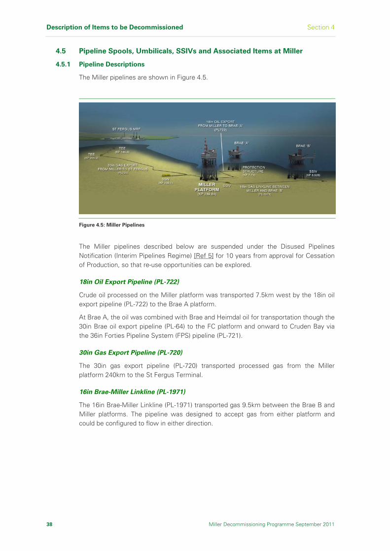
Description of Items to be Decommissioned Section 4
38 Miller Decommissioning Programme September 2011
4.5 Pipeline Spools, Umbilicals, SSIVs and Associated Items at Miller
4.5.1 Pipeline Descriptions
The Miller pipelines are shown in Figure 4.5.
Figure 4.5: Miller Pipelines
The Miller pipelines described below are suspended under the Disused Pipelines Notification (Interim Pipelines Regime) [Ref 5] for 10 years from approval for Cessation of Production, so that re-use opportunities can be explored.
18in Oil Export Pipeline (PL-722)
Crude oil processed on the Miller platform was transported 7.5km west by the 18in oil export pipeline (PL-722) to the Brae A platform.
At Brae A, the oil was combined with Brae and Heimdal oil for transportation though the 30in Brae oil export pipeline (PL-64) to the FC platform and onward to Cruden Bay via the 36in Forties Pipeline System (FPS) pipeline (PL-721).
30in Gas Export Pipeline (PL-720)
The 30in gas export pipeline (PL-720) transported processed gas from the Miller platform 240km to the St Fergus Terminal.
16in Brae-Miller Linkline (PL-1971)
The 16in Brae-Miller Linkline (PL-1971) transported gas 9.5km between the Brae B and Miller platforms. The pipeline was designed to accept gas from either platform and could be configured to flow in either direction.
Section 4 Description of Items to be Decommissioned
Miller Decommissioning Programme September 2011 39
4.5.2 Items to be Removed
To enable removal of the topside modules and jacket, the following items are to be removed at Miller and returned to shore for reuse, recycling or disposal:
Spoolpieces:
30in gas export pipeline (PL-720) spoolpieces connecting the riser at the base of the jacket to the Subsea Isolation Valve (SSIV) and the SSIV to the pipeline. These consist of approximately 16 steel pipe sections of which 13 are concrete coated
18in oil export pipeline (PL-722) spoolpieces connecting the riser at the base of the jacket to the pipeline. These consist of approximately seven steel pipe sections
16in Brae-Miller Linkline (PL-1971) spoolpieces connecting the riser to the SSIV and the SSIV to the pipeline. These consist of approximately 16 steel pipe sections
SSIVs:
30in gas export pipeline SSIV structure. The structure is piled to the seabed and is an integral structure consisting of the valves, piping and protection frame
16in gas import pipeline SSIV structure. This is a ballasted gravity structure and consists of a separate valve skid and a protection frame
Umbilicals:
30in gas export pipeline SSIV control umbilical from the base of the jacket to the SSIV. This consists of approximately 296m of 93mm diameter electro-hydraulic umbilical containing six hydraulic hoses and nine electrical signal conductors
16in gas import pipeline SSIV control umbilical (PLU-1973) from the base of the jacket to the SSIV. This consists of approximately 147m of 61mm diameter electro-hydraulic umbilical containing two hydraulic hoses and two electrical signal conductors
Protection Features:
Flexible concrete mattresses which protect the 30in gas export SSIV control umbilical from the base of the jacket to the SSIV
Flexible concrete mattresses which support the 30in gas export SSIV control umbilical where it crosses over the 18in oil export pipeline
Concrete block that supports the 30in gas export SSIV control umbilical where it exits the j-tube on the jacket
Grout/sand bags that support the 30in gas export SSIV control umbilical where it exits the j-tube on the jacket
Flexible concrete mattresses which protect the 16in gas import spoolpieces and the SSIV control umbilical from the base of the jacket to the SSIV
Grout/sand bags that support the 16in gas import SSIV control umbilical where it exits the j-tube on the jacket
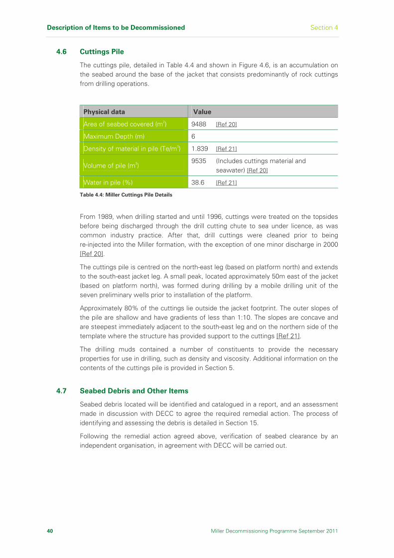
Description of Items to be Decommissioned Section 4
40 Miller Decommissioning Programme September 2011
4.6 Cuttings Pile
The cuttings pile, detailed in Table 4.4 and shown in Figure 4.6, is an accumulation on the seabed around the base of the jacket that consists predominantly of rock cuttings from drilling operations.
Physical data Value
Area of seabed covered (m2) 9488 [Ref 20]
Maximum Depth (m) 6
Density of material in pile (Te/m3) 1.839 [Ref 21]
Volume of pile (m3) 9535 (Includes cuttings material and
seawater) [Ref 20]
Water in pile (%) 38.6 [Ref 21]
Table 4.4: Miller Cuttings Pile Details
From 1989, when drilling started and until 1996, cuttings were treated on the topsides before being discharged through the drill cutting chute to sea under licence, as was common industry practice. After that, drill cuttings were cleaned prior to being re-injected into the Miller formation, with the exception of one minor discharge in 2000 [Ref 20].
The cuttings pile is centred on the north-east leg (based on platform north) and extends to the south-east jacket leg. A small peak, located approximately 50m east of the jacket (based on platform north), was formed during drilling by a mobile drilling unit of the seven preliminary wells prior to installation of the platform.
Approximately 80% of the cuttings lie outside the jacket footprint. The outer slopes of the pile are shallow and have gradients of less than 1:10. The slopes are concave and are steepest immediately adjacent to the south-east leg and on the northern side of the template where the structure has provided support to the cuttings [Ref 21].
The drilling muds contained a number of constituents to provide the necessary properties for use in drilling, such as density and viscosity. Additional information on the contents of the cuttings pile is provided in Section 5.
4.7 Seabed Debris and Other Items
Seabed debris located will be identified and catalogued in a report, and an assessment made in discussion with DECC to agree the required remedial action. The process of identifying and assessing the debris is detailed in Section 15.
Following the remedial action agreed above, verification of seabed clearance by an independent organisation, in agreement with DECC will be carried out.

Section 4 Description of Items to be Decommissioned
Miller Decommissioning Programme September 2011 41
Figure 4.6: Miller Cuttings Pile Bathymetry

Description of Items to be Decommissioned Section 4
42 Miller Decommissioning Programme September 2011
I n t e n t i o n a l l y L e f t B l a n k
Section 5 Inventory of Materials
Miller Decommissioning Programme September 2011 43
5 Inventory of Materials
This section gives information on the materials that will be present at the
facilities prior to removal.
5.1 Introduction
This inventory is indicative of the materials expected to be present prior to the removal of the topsides modules and jacket, once the topsides are free of gross hydrocarbon, isolated from the reservoir with all conductors, casing, tubing and other wells equipment removed, and the process plant has been engineered down.
5.2 Topsides Modules
Table 5.1 lists an inventory of the material in the topsides modules with each module containing different materials depending on the type of facilities present. The weight data is contained within a Platform Materials Inventory [Ref 6] which was compiled from the weight database and other studies, and will continue to be developed as the decommissioning activities progress.
5.3 Jacket and Drilling Template
Table 5.2 lists an inventory of the materials in the jacket and the drilling template.
5.4 Wells and Platform Conductors
Table 5.3 lists the material from the Miller wells and conductors that will be removed prior to the removal of the topsides modules and the platform being gross hydrocarbons free.
5.5 Pipeline Spools, Umbilicals, SSIVs and Associated Items at Miller
Table 5.4 lists the material from the Miller pipelines that will be removed.
5.6 Cuttings Pile
Table 5.5 lists an inventory of selective contaminants known to be present within the cuttings pile. The weight of each contaminant has been calculated based on their worst-case maximum predicted concentrations [Ref 22], [Ref 23] the cuttings pile volume [Ref 20] and cuttings pile material density [Ref 21]. The remainder of the cuttings pile is made up of a mixture of drill cuttings, diesel, low toxicity oil based drilling mud, barite, water, and other contaminants.
5.7 Seabed Debris and Other Items
All items of oilfield debris identified will be categorised and, in consultation with DECC, a management plan will be agreed (refer to Section 15 for further details).
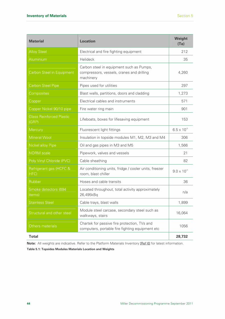
Inventory of Materials Section 5
44 Miller Decommissioning Programme September 2011
Material Location Weight
(Te)
Alloy Steel Electrical and fire fighting equipment 212
Aluminium Helideck 35
Carbon Steel in Equipment Carbon steel in equipment such as Pumps, compressors, vessels, cranes and drilling machinery
4,260
Carbon Steel Pipe Pipes used for utilities 297
Composites Blast walls, partitions, doors and cladding 1,273
Copper Electrical cables and instruments 571
Copper Nickel 90/10 pipe Fire water ring main 901
Glass Reinforced Plastic (GRP)
Lifeboats, boxes for lifesaving equipment 153
Mercury Fluorescent light fittings 6.5 x 10⁻⁵
Mineral Wool Insulation in topside modules M1, M2, M3 and M4 306
Nickel alloy Pipe Oil and gas pipes in M3 and M5 1,566
NORM scale Pipework, valves and vessels 21
Poly Vinyl Chloride (PVC) Cable sheathing 82
Refrigerant gas (HCFC & HFC)
Air conditioning units, fridge / cooler units, freezer room, blast chiller
9.0 x 10⁻²
Rubber Hoses and cable transits 36
Smoke detectors (694 items)
Located throughout, total activity approximately 26,495kBq
n/a
Stainless Steel Cable trays, blast walls 1,899
Structural and other steel Module steel carcase, secondary steel such as walkways, stairs
16,064
Others materials Chartek for passive fire protection, TVs and computers, portable fire fighting equipment etc
1056
Total 28,732
Note: All weights are indicative. Refer to the Platform Materials Inventory [Ref 6] for latest information.
Table 5.1: Topsides Modules Materials Location and Weights

Section 5 Inventory of Materials
Miller Decommissioning Programme September 2011 45
Material Template
(Te)
Jacket/Footings
(Te)
Aluminium and Alloys 19 203
Cement - 588
Copper - <1
Marine Growth - 1,657
Other Materials - 148
Paint <1 29
Poly Vinyl Chloride (PVC) - <1
Structural and other Steel 129 15,959
Total 148 18,584
Note: All weights are indicative. Refer to the Platform Materials Inventory [Ref 6] for latest information.
Table 5.2: Drilling Template and Jacket/Footings Material Weights
Item Material Weight
(Te)
Steel (1) 1,652 Conductors and casing
Cement 532
Steel 309 Tubing and other equipment
NORM scale 70
Total estimated weight removed from wells 2563
Notes: (1) Estimated weight from well programmes. (2) All weights are indicative. Refer to the Platform Materials Inventory [Ref 6] for latest information.
Table 5.3: Wells and Conductors Removed Material Weights

Inventory of Materials Section 5
46 Miller Decommissioning Programme September 2011
Pipeline Item Material Weight
(Te)
30in spool at Miller
265m (total approx length, inc SSIV spool)
Line pipe and bends Steel 43
Flanges Steel 10
Weight Coat Concrete 35
Anodes Zinc 2
30in spool at SSIV
(length inc above) Line pipe and bends
Steel 59
Flanges Steel 10
Weight Coat Concrete 52
Anodes Zinc 2
SSIV structure SSIV inc pipework, flanges, valves and fittings
Steel 338
Piles Steel 43
Protection Features 2 Flexible Concrete Mats at J-tube exit
Concrete 7
1 Triangular Concrete Support Block at J-tube exit
Concrete 3
400 Grout Bags at J-tube exit
Grout 10
55 Concrete Mats covering umbilical length
Concrete 194
18 Concrete Mats supports either side of crossing over 18in pipeline
Concrete 79
30in Gas Export Pipeline (PL-720)
7 Concrete Mats over umbilical at crossing
Concrete 15
18in Spool at Miller
272m (approx length) Line pipe and bends
Steel 25
Flanges Steel 6
18in Oil Export Pipeline (PL-722)
Anodes Zinc 2
Note: All weights are indicative. Refer to the Platform Materials Inventory [Ref 6] for latest information.
Table 5.4: Pipeline Spools, Umbilicals, SSIVs and Associated Removed Items Material Weights (sheet 1 of 2)

Section 5 Inventory of Materials
Miller Decommissioning Programme September 2011 47
Pipeline Item Material Weight
(Te)
16in spool at Miller
367m (approx length) Line pipe and bends
Steel 70
Flanges Steel 6
Anodes Zinc <1
SSIV structure SSIV inc pipework, flanges, valves and fittings
Steel 45
Protection Structure
Steel 42
Anodes Zinc 3
Roof Panel Steel 14
Protection Features 43 Flexible Concrete mats on Miller Spoolpiece and umbilical
Concrete 180
16in Brae-Miller Linkline (PL-1971)
23 Grout Bags on Control Umbilical at Guide
Grout <1
Gas Export Pipeline SSIV Control Umbilical
Electro Hydraulic/ Control Umbilical Composite 6
Electro Hydraulic/ Control Umbilical Composite 1 Brae-Miller Linkline SSIV Control Umbilical (PLU-1973) Umbilical Guide Steel <1
Total estimated weight 1304
Note: All weights are indicative. Refer to the Platform Materials Inventory [Ref 6] for latest information.
Table 5.4: Pipeline Spools, Umbilicals, SSIVs and Associated Removed Items Material Weights (sheet 2 of 2)
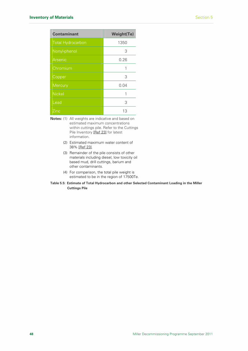
Inventory of Materials Section 5
48 Miller Decommissioning Programme September 2011
Contaminant Weight(Te)
Total Hydrocarbon 1350
Nonyl-phenol 3
Arsenic 0.26
Chromium 1
Copper 3
Mercury 0.04
Nickel 1
Lead 3
Zinc 13
Notes: (1) All weights are indicative and based on estimated maximum concentrations within cuttings pile. Refer to the Cuttings Pile Inventory [Ref 23] for latest information.
(2) Estimated maximum water content of 38% [Ref 23].
(3) Remainder of the pile consists of other materials including diesel, low toxicity oil based mud, drill cuttings, barium and other contaminants.
(4) For comparison, the total pile weight is estimated to be in the region of 17500Te.
Table 5.5: Estimate of Total Hydrocarbon and other Selected Contaminant Loading in the Miller
Cuttings Pile

Section 6 Removal and Disposal Options
Miller Decommissioning Programme September 2011 49
6 Removal and Disposal Options
This section provides a description of how screening of the
decommissioning options for each item to be decommissioned was carried
out and how the recommended option was selected.
6.1 Reuse, Alternative Use and Decommissioning Options
Prior to the assessment of removal and disposal options, the Miller Section 29 Notice Holders undertook a process to look at the potential reuse and alternative uses for the Miller Platform in order to determine whether alternatives to decommissioning were available. This process commenced prior to Cessation of Production (CoP) on Miller and culminated in the submission of the CoP Application [Ref 7].
Currently, the Miller platform continues to host a Search and Rescue (SAR) helicopter, as an integral part of provision of offshore rescue and recovery operations in the central North Sea area. Prior to the commencement of topsides removal, the helicopter will be relocated from the Miller platform.
6.1.1 Reuse
Although a minor number of disused offshore facilities are successfully reused in other parts of the world, the concept is relatively new in the North Sea, where structures similar to Miller are generally built for the specific requirements of the field they service. Several studies were carried out to assess the opportunities for reuse within the industry.
Factors including the remote location, difficulty of access, extreme weather, high maintenance costs and the design life influence the options for the Miller platform.
The following options were considered:
Oil and Gas Reuse at Present Location
Various studies of potential oil and gas reserves in the area surrounding Miller were carried out during the life of the Field [Ref 24], [Ref 25]. These studies indicated that there are no commercial oil and gas reserves that could be accessed to extend the life of the Miller platform. The results of these studies formed the basis of the CoP Application [Ref 7] prepared for the platform and approved by DECC in September 2007.
This option was eliminated and not considered further.
Oil and Gas Reuse at Alternative Location
The production facilities at Miller are based on 1980s technology, some of which might be inefficient. Wholesale redeployment of the facility is not appropriate, and would require the topsides to be removed in a manner similar to that described for decommissioning.
Attempts to reuse parts of the platform will be a key part of the disposal process.

Removal and Disposal Options Section 6
50 Miller Decommissioning Programme September 2011
New or Alternative Use
Studies into new use opportunities outside the oil and gas industry were carried out by the Miller Section 29 Notice Holders [Ref 24]. Alternative uses evaluated included carbon capture and storage facilities, wind farms, marine research stations, wave power plants, fish farming sites and training centres.
None of the new or alternative use opportunities were found to be economically viable.
6.1.2 Decommission
Since no viable reuse or alternative use opportunities have been identified, the option to reuse the platform was not considered to be feasible and not taken forward for further assessment. Therefore the Miller Section 29 Notice Holders recommendation is to decommission the Miller facilities.
Recommendation
The Miller facilities are decommissioned.
6.2 Assessment Methodology
6.2.1 Introduction
The Miller Section 29 Notice Holders developed and implemented a robust assessment methodology to determine the best decommissioning option for each of the items to be decommissioned.
Responsible decommissioning of disused oil and gas facilities is integral to the exploration and production business lifecycle. Ensuring that the Miller facilities decommissioning process achieves a balance of the highest, practicable safety, environmental, technical, societal and economic standards, is the basis of all removal and disposal activities.
Decommissioning of disused offshore Installations is governed under UK law by the Petroleum Act 1998 [Ref 1] as amended by the Energy Act 2008 [Ref 2]. The UK also adheres to the 1992 Oslo and Paris (OSPAR) Convention [Ref 26] for the Protection of the Marine Environment of the Northeast Atlantic. Specific agreement on the decommissioning of offshore Installations is set out in OSPAR Decision 98/3 [Ref 4].
The DECC Guidance Notes [Ref 3] state that the decommissioning programme should be consistent with international obligations and take into consideration:
The precautionary principle
Best available techniques and best environmental practice
Waste hierarchy principles
Other users of the sea
Health and safety law

Section 6 Removal and Disposal Options
Miller Decommissioning Programme September 2011 51
Proportionality
Cost effectiveness
The waste hierarchy principle is particularly important and is a key element in OSPAR Decision 98/3 [Ref 4]. The conceptual framework, which translates sustainability into practice, advocates that the management of waste should follow the reduce, reuse, recycle and dispose principle. This framework forms the core of the Miller decommissioning waste management strategy.
Additionally, the business values and policies of the Miller Section 29 Notice Holders will underpin the process of preparing for decommissioning, particularly with regard to the five key assessment criteria which are safety, environmental, technical, societal and economics.
These guiding principles formed the process by which the Miller Section 29 Notice Holders identified and assessed the decommissioning options to balance all the factors, and seek to meet the needs of stakeholders wherever possible.
6.2.2 Decommissioning Studies
The Miller Section 29 Notice Holders adopted a long-term and comprehensive approach to studying the decommissioning requirements of the Miller platform. Over 40 studies were undertaken by the Miller Section 29 Notice Holders and they are listed in Section 17.
The objectives of the studies were to:
Determine if there was further uses for the platform, either at its present location or at other locations
Examine issues associated with the full removal of the Miller platform and all associated material to achieve a clear seabed
Describe and compare the alternative options for the Miller decommissioning items under the requirements of the Petroleum Act 1998 [Ref 1] as amended by the Energy Act 2008 [Ref 2] and where applicable, OSPAR Decision 98/3 [Ref 4]
Define and understand certain areas of decommissioning universally acknowledged as challenging, eg Joint Industry Projects (JIPs)
6.2.3 Jacket Comparative Assessment Studies
To meet OSPAR Decision 98/3 [Ref 4], the Miller Section 29 Notice Holders are obliged to undertake a specific process of comparative assessment to allow authoritative and comparative evaluation of complete jacket removal against alternative options. This is unique to the jacket and does not apply to other elements of the decommissioning scope. The DECC Guidance Notes [Ref 3] identifies assessment criteria in five areas which are safety, environmental, technical, societal and economic.
Safety Evaluation
Identifying and quantifying the major safety risks to all personnel involved in the decommissioning operations is a major part of the assessment.
Removal and Disposal Options Section 6
52 Miller Decommissioning Programme September 2011
The Safety Case Regulations [Ref 27] require that a Dismantlement Safety Case is prepared prior to any decommissioning activities associated with platform removal taking place. The Duty Holder, by means of the Safety Case, must demonstrate that So Far As Is Reasonably Practicable (SFAIRP) the proposed arrangements for decommissioning have reduced the risks to personnel to As Low As Reasonably Practicable (ALARP).
A core part of the assessment process is the identification of all hazards associated with the decommissioning work, an assessment of the associated risk and whether the level of risk is acceptable.
QRA techniques were used to provide a numerical evaluation of the risks. These were expressed as Potential Loss of Life (PLL), which estimates the collective risk to all workers exposed by the project activities, and Individual Risk Per Annum (IRPA), which estimates the likelihood of an individual becoming a fatality in any one year while exposed to project activities.
PLL and IRPA are directly related in terms of the number of people and the time spent on the project activities.
PLL = IRPA x number of people working on the project fraction of time working per year
The BP criterion for acceptability of risk is that the risk of fatality for an individual shall not be greater than 5 x 10⁻⁴ per year (ie 1 in 2000).
The Health and Safety Executive (HSE) defines the maximum tolerable level of individual risk of fatality as 1 x 10⁻³ per year (ie 1 in 1000) [Ref 10].
The QRA [Ref 28] was undertaken using an established technique to provide an estimate of removal and disposal risks.
Although numerical values can help with the calculations of safety risk, decisions about human lives at risk cannot be reduced to numbers alone. There is always uncertainty associated with a proposed activity and therefore other factors, such as engineering, operational and qualitative analysis, must also be taken into account. This is the situation with the decommissioning of large fixed steel structures, due to the lack of industry experience.
Environmental Impact
Evaluating the impact of decommissioning activities on the offshore, and inshore and onshore environment is a key part of the comparative assessment.
This assessment and comparison of the differences in environmental impacts between the removal options (ie full and partial jacket removal) was based on an Environmental Impact Assessment (EIA) [Ref 29] which was carried out in accordance with widely recognised techniques and standard methodologies.
The scope of the EIA [Ref 29] included the impacts of all activities at the offshore location and involving both developing and existing removal methods based on conceptual studies or contractor data. A generic assessment was undertaken for an inshore / onshore dismantling and disposal site as the exact location is unknown at this stage.

Section 6 Removal and Disposal Options
Miller Decommissioning Programme September 2011 53
The EIA [Ref 29] identified and evaluated the potential environmental impacts to provide an understanding of their associated effects in order to compare the different options and removal methods that had been considered.
For the EIA [Ref 29], the following nine impact sources associated with jacket removal were identified:
Emissions to air
Discharges to sea
Seabed disturbance
Spill risk
Underwater noise
Interaction with other sea users
Waste
Onshore issues / community disturbance
Inshore issues
The assessment process was predominantly qualitative, except where suitable data was available.
The assessment included consideration of the impact on climate change from vessel emissions and those associated with the reprocessing of recovered material. The energy and emissions calculations were based on the Energy Institute (formerly Institute of Petroleum) Guidelines for the Calculations of Estimates of Energy Use and Gaseous Emissions in the Decommissioning of Offshore Structures [Ref 30].
Technical Feasibility
To assess the various aspects of decommissioning the Miller facilities, the Miller Section 29 Notice Holders commissioned technical studies from a number of recognised experts and competent contractors.
The assessment of the technical feasibility of different decommissioning options was based primarily on existing industry experience and available equipment. There is very limited industry experience of decommissioning large steel structures.
Consideration was given to new decommissioning technologies, and the Miller Section 29 Notice Holders participated in study work to assess the development of new decommissioning technologies. None of these technologies are currently available, but this does not preclude new technologies being considered in the evaluation process. QRA techniques, engineering and operational analysis have been used in combination to provide comprehensive robust quantitative and qualitative assessments of each option. These were then used in the decision making process for the selected option.
The feasibility of activities, operations or options, and their associated technical risks were assessed by evaluating a number of key issues including:
Availability of equipment
Complexity of operations
Level of industry experience relating to the operation
Removal and Disposal Options Section 6
54 Miller Decommissioning Programme September 2011
Likelihood that a major failure would occur
Implications for the option if a failure were to occur
Societal Impact
The assessment measured the impact on society of all decommissioning activities and potential options.
The most significant areas assessed were:
Impact on other sea users, primarily the commercial fishing industry
Impact on neighbours to onshore dismantlement and disposal sites
Economic impact, as measured by the employment created and income generated from different activities
Participation of representative groups from society in the consultation process is very important and as many different organisations and individuals as possible will be invited to take part.
Various stakeholder engagement processes have and will continue to be used, including:
Face-to-face meetings
Written correspondence
An interactive website
Economic Assessment
Cost estimates for decommissioning the Miller platform have been developed and are based on input from specialist contractors, comparison with industry norms and incorporation of data from previous decommissioning activity.
The estimated costs are presented as a range of possible costs and were compiled on the basis of:
Industry knowledge of the planning, operations, procedures and contingencies required for activities such as decommissioning
Unit costs of equipment, plant and personnel
All estimates are subject to significant uncertainty due to:
The limited number of completed decommissioning projects for benchmarking
Potential for weather related delays
Limited number of vessels capable of lifting the modules and jacket
Qualitative Levels
The performance of each option in each of the five key assessment criteria was assigned to one of three qualitative levels of acceptability as defined in Table 6.1.

Section 6 Removal and Disposal Options
Miller Decommissioning Programme September 2011 55
Level of Acceptability Risk Factors
Nature of
Assessment Acceptable Marginal Unacceptable
Safety Mainly Quantitative
A region of low risk – broadly acceptable region risks in this area are generally regarded as insignificant and adequately controlled.
IRPA is well within the recognised threshold of 1 in 1000 [Ref 10].
A region of intermediate risk – tolerable region where people are prepared to tolerate the risk to secure the benefits.
IRPA is around the recognised threshold of 1 in 1000 [Ref 10].
A region of high risk - region considered unacceptable whatever the level of benefit associated with the activity.
IRPA is above the recognised threshold of 1 in 1000 [Ref 10].
Environmental Quantitative / Qualitative
The proposed operations may provide a benefit, no change or at worst negligible environmental impacts.
The proposed operations cause some, possibly significant, environmental disturbance that is localised and of short duration.
The proposed operations cause significant environmental disturbance that is widespread and / or long lasting.
Technical Mainly Qualitative
Equipment and techniques are known and have a track record of success.
Equipment and techniques have a limited track record or require development.
Equipment and techniques have no track record.
Societal Mainly Qualitative
There are tangible positive benefits or possibly no discernible negative impacts.
The proposed operations may result in small impacts.
There is a significant disamenity.
Economic Quantitative Cost is important but is not used as a prime differentiator. It is included for completeness and as a measure of proportionality when considering the other four criteria.
Table 6.1: Assessment Acceptability Criteria
6.2.4 Independent Review
In recognition of independent reviews that were undertaken for other decommissioning projects, the Miller Section 29 Notice Holders invited an independent engineering and project management consultancy group to review those comparative assessment studies that are unique to Miller and materially different to previous decommissioning projects. The Independent Review Consultant (IRC) was tasked to assess the Miller studies for adequacy of scope and methodology, clarity, completeness, relevance and objectivity of conclusions.
Details of the IRC process and findings are described in Section 14.

Removal and Disposal Options Section 6
56 Miller Decommissioning Programme September 2011
6.2.5 Stakeholder Consultation
The Miller Section 29 Notice Holders recognise that a purely scientific assessment of the impacts and risks will not reflect the views of all stakeholders, particularly when the different risks and benefits are valued differently by different stakeholder groups. An ongoing consultation process with stakeholders was agreed as an effective way of reaching a balanced solution for the decommissioning of Miller.
Details of the stakeholder consultation process are contained in Section 11.
6.3 Topsides Modules Decommissioning
Under the terms of OSPAR Decision 98/3 [Ref 4], there is a prohibition on the dumping and leaving wholly or partly in place of offshore Installations. Accordingly the topsides of all Installations must be returned to shore for reuse, recycle or disposal. Studies carried out by the Section 29 Notice Holders, and data from other projects, indicate that removal of the Miller topsides is technically feasible [Ref 31], [Ref 32], [Ref 33], [Ref 34], [Ref 35], [Ref 36].
Certain aspects of the way in which the Miller topsides were installed will present some technical and engineering problems during removal operations. An indicative topsides removal activity, using a Heavy Lift Vessel (HLV) as shown in Figure 6.1, is essentially the reverse of the installation process.
The removal operations will be technically challenging and will require detailed planning and rigorous management to ensure that these activities can be completed safely and with minimum environmental impact.
Accordingly, only the option of complete removal to shore has been considered for the Miller topsides.
The Miller Section 29 Notice Holders have a high degree of confidence that existing proven technologies are available to undertake the safe removal and transportation of the topsides to an onshore location for reuse, recycling or disposal.
Recommendation
The topsides modules are removed and returned to shore for reuse, recycling or disposal.

Section 6 Removal and Disposal Options
Figure 6.1: Indicative Topsides Removal Activity
Miller Decommissioning Programme September 2011 57
Removal and Disposal Options Section 6
58 Miller Decommissioning Programme September 2011
6.4 Jacket Decommissioning
6.4.1 Introduction
Whilst the OSPAR Decision 98/3 [Ref 4] prohibits the dumping and leaving jackets wholly or partly in place, it recognises the difficulties in removing the footings of large steel jackets weighing over 10,000Te and installed prior to 9th February 1999. As a result, there is a facility for derogation from the main requirement.
Miller qualifies for consideration of derogation from OSPAR Decision 98/3 [Ref 4] because the jacket weight is greater than 10,000Te and it was installed prior to 1999.
The Miller Section 29 Notice Holders used a screening and evaluation process to arrive at the options for decommissioning the Miller jacket. This was designed to assess the technical, safety, environmental, societal and economic impact of each option and is consistent with the DECC Guidance Notes [Ref 3].
Decommissioning of the jacket and cuttings pile have been evaluated separately to ensure each was considered on its own merits, although this is a factor for complete jacket removal as the cuttings pile would have to be disturbed, displaced or removed to gain access to the base of the footings, seabed brace members and template.
6.4.2 Jacket Decommissioning Options
Partial removal of the footings, ie cutting through the bottles legs above the level of the drill cuttings, was considered in the North West Hutton Decommissioning Programme (Ref 47]. The assessment in the North West Hutton programme showed that partial removal of the footings has technical risks and uncertainties of a similar or greater magnitude to those of complete removal of the jacket. Safety risks were also higher for partial removal as a direct result of this technical uncertainty. The bottle legs on North West Hutton are approximately 10m in diameter with steel up to 70mm thick, whereas for Miller the bottle legs are 15m diameter and steel thicknesses up to 80mm. By comparison, Miller bottles present the same or greater risks and technical uncertainties than North West Hutton; hence for Miller, as for North West Hutton, full jacket removal is preferable to the option of partial footings removal.
Leaving the bottle legs and piles in place and removing the jacket base plan bracing is a variation on partial footings removal for Miller. The base plan bracing is at a level of -97m, which is 5m above the seabed. The greatest depth of the drill cuttings is 6m at one of the bottle legs, which means the plan bracing in this area is covered in drill cuttings. Removal of the plan bracing has technical risks and uncertainties, which would involve disturbance of the drill cuttings and temporary supports or piece small removal of the bracing. Even if this work were undertaken, the bottle legs and piles still remain on the seabed as the greatest mass of steel; and removal of the bracing does not reduce the ‘foot-print’ of the jacket footings with regard to any fishing hazard.
In summary for Miller, as for North West Hutton, there is no advantage to the partial removal of the footings over either full jacket removal or partial jacket removal. Consequently the two options evaluated for the decommissioning of the Miller jacket are full jacket removal or partial jacket removal, as described below:

Section 6 Removal and Disposal Options
Full Jacket Removal
This option would remove all elements of the jacket, including the footings to the original seabed level. The drilling template and piles to 3m below the seabed would also be removed. The jacket would be recovered and brought ashore for recycling and disposal.
Partial Jacket Removal
Removal of the upper portion of the jacket down to the top of the foundations at a depth of approximately 80m below sea level, as shown in Figure 6.2, leaving the jacket footings in place.
The DECC Guidance Notes [Ref 3] describe the footings as the highest upstand of the foundation, or piles, of the jacket. For Miller this elevation is coincident with the 4.5m to 6.0m transition on the four corner legs of the jacket. For practical purposes, the Miller Section 29 Notice Holders have determined the top of this transition is the top of the footings. The top portion of the jacket would be recovered to shore for recycling and disposal; the footings would be left in place to degrade naturally.
The drilling template would be left in situ, being wholly obstructed by the plan bracing of the jacket below the top of the footings.
Using the methodology prescribed in the DECC Guidance Notes [Ref 3] and the comparative assessment studies described in Section 6.2.3, a comparative assessment of the options was undertaken to determine the preferred option of decommissioning of the Miller jacket.
Figure 6.2: Indicative Partial Jacket Removal showing Footings and Drilling Template
Miller Decommissioning Programme September 2011 59
Removal and Disposal Options Section 6
60 Miller Decommissioning Programme September 2011
6.4.3 Jacket Removal Comparative Assessment
Studies have been undertaken with a number of contractors [Ref 32], [Ref 33], [Ref 36] to look at the feasibility of full and partial removal of the jacket as a series of offshore lifts. An indicative partial jacket removal activity, using a HLV is shown in Figure 6.3.
Both full and partial jacket removal would require a period of intensive offshore operational activity involving a large numbers of vessels, equipment and personnel. Heavy lift equipment is currently available, in the form of Semi-Submersible Crane Vessels (SSCVs) to undertake this scope of work. These vessels have the required capacity to remove the jacket sections. However, not even the largest SSCVs can remove the Miller jacket and footings as a single lift. Whilst it is recognised that new and innovative single lift technologies are currently in the early stages of development, these technologies have not matured to a point where they can be considered.
The studies have demonstrated the feasibility of removal of the Miller jacket using existing heavy lift technologies. The comparative assessment of the removal options has therefore been based on existing technologies. The following section of this Decommissioning Programme discusses the comparative assessment of options in the areas of safety evaluation, environmental impact, technical feasibility, societal impact and economic assessment.

Section 6 Removal and Disposal Options
Miller Decommissioning Programme September 2011 61
Figure 6.3: Indicative Partial Jacket Removal Activity
Removal and Disposal Options Section 6
62 Miller Decommissioning Programme September 2011
Safety Evaluation
To establish the comparative differences in safety risk for the jacket removal options, the Miller Section 29 Notice Holders used the well-established technique of QRA [Ref 28]. The approach this study took was a balanced view of major accident hazards and occupational hazards. The key aspects of the approach are as follows:
Major hazards were analysed using fault and event trees
Occupational hazards for each activity were evaluated based on work task details, number of personnel involved in work tasks, task duration and the fatal accidents rates were established by JIPs [Ref 37], [Ref 38]
The QRA [Ref 28] established the estimated number of fatalities or PLL, based on the scenario of using existing technology. Contractor-provided information was used to enable estimates of the number of personnel involved in each work task and the task durations to be made.
It should be noted that the risk figures have not taken into account the potential use of divers or explosives. The implications of using these resources would increase the risk figures and this is believed to impact the full jacket removal option more significantly due to the greater potential for technical failure.
The principal risks associated with the different removal options result from the following hazards:
Occupational hazards such as working at heights, basket transfers and over-side working, as well slips, trips and falls
Hazards associated with the typical removal tasks such as rope access, lifting, cutting, material handling
Floating vessel hazards such as loss of station keeping capability, ballasting failure
Hazards posed by other shipping activity in the work area such as passing or attendant ship collision with a HLV
Hazards associated with background activities on a HLV such as accommodation fires, engine room fires
Hazards associated with the typical activities undertaken by a HLV such as dropped heavy object during lifting operations, fallings debris, material handling and construction activities
Hazards associated with barge operations involved in the handling, sea-fastening and transportation of large, heavy and bulky items
Port hazards
Further information on the hazards associated with the decommissioning activities is included in Table 6.2.
Although every endeavour will be made to carry out the Miller Decommissioning Programme without the need for divers, the hazard has been included for completeness.
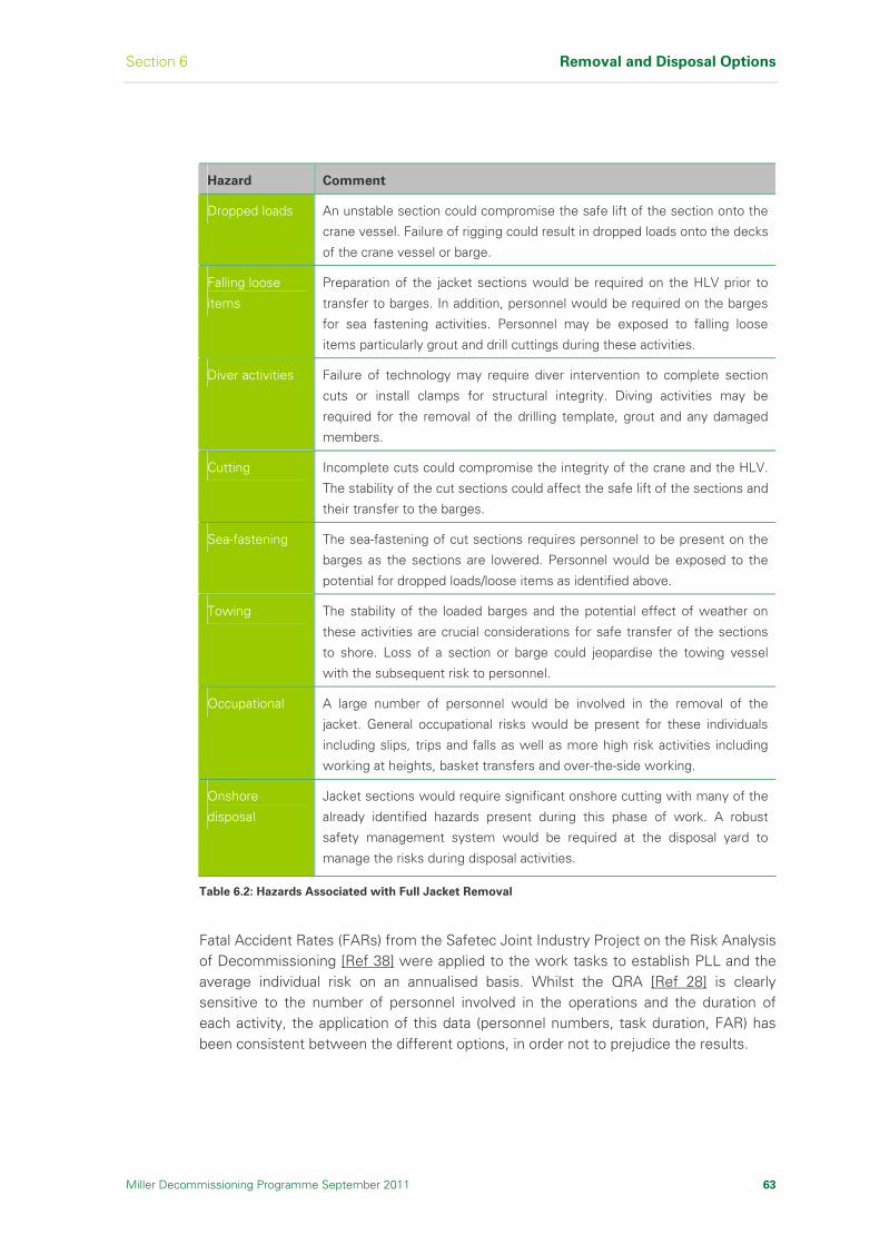
Section 6 Removal and Disposal Options
Miller Decommissioning Programme September 2011 63
Hazard Comment
Dropped loads An unstable section could compromise the safe lift of the section onto the
crane vessel. Failure of rigging could result in dropped loads onto the decks
of the crane vessel or barge.
Falling loose
items
Preparation of the jacket sections would be required on the HLV prior to
transfer to barges. In addition, personnel would be required on the barges
for sea fastening activities. Personnel may be exposed to falling loose
items particularly grout and drill cuttings during these activities.
Diver activities Failure of technology may require diver intervention to complete section
cuts or install clamps for structural integrity. Diving activities may be
required for the removal of the drilling template, grout and any damaged
members.
Cutting Incomplete cuts could compromise the integrity of the crane and the HLV.
The stability of the cut sections could affect the safe lift of the sections and
their transfer to the barges.
Sea-fastening The sea-fastening of cut sections requires personnel to be present on the
barges as the sections are lowered. Personnel would be exposed to the
potential for dropped loads/loose items as identified above.
Towing The stability of the loaded barges and the potential effect of weather on
these activities are crucial considerations for safe transfer of the sections
to shore. Loss of a section or barge could jeopardise the towing vessel
with the subsequent risk to personnel.
Occupational A large number of personnel would be involved in the removal of the
jacket. General occupational risks would be present for these individuals
including slips, trips and falls as well as more high risk activities including
working at heights, basket transfers and over-the-side working.
Onshore
disposal
Jacket sections would require significant onshore cutting with many of the
already identified hazards present during this phase of work. A robust
safety management system would be required at the disposal yard to
manage the risks during disposal activities.
Table 6.2: Hazards Associated with Full Jacket Removal
Fatal Accident Rates (FARs) from the Safetec Joint Industry Project on the Risk Analysis of Decommissioning [Ref 38] were applied to the work tasks to establish PLL and the average individual risk on an annualised basis. Whilst the QRA [Ref 28] is clearly sensitive to the number of personnel involved in the operations and the duration of each activity, the application of this data (personnel numbers, task duration, FAR) has been consistent between the different options, in order not to prejudice the results.

Removal and Disposal Options Section 6
64 Miller Decommissioning Programme September 2011
The QRA studies [Ref 28] indicate that for full jacket removal the PLL is 0.09. For partial jacket removal the PLL is 0.06, which is 33% lower than for full jacket removal. For both options over 90% of the risk is attributable to occupational hazards with less than 10% attributable to major accident hazards. The QRA studies also predict that the average individual risk per removal operation is 33% lower for the partial jacket removal operation compared to the full jacket removal option.
In summary, the studies predict that the risks to personnel would be 50% higher if the full jacket removal option were implemented, rather than the partial jacket removal option where the footings are left in place.
The increase in safety risk for the full jacket removal option, as measured by PLL is in part due to the longer time frame and increased number of heavy lifts required. There are a number of further areas of safety risk which are specific to the full jacket removal option, and include:
Increased vessel requirements such as the requirement for more barges and supply vessel support
The subsea construction activity associated with the support of the bottle legs during removal, which would need substantial engineering
Increased probability of dropped objects onto the deck of the vessels, including the drill cuttings as they dry out, grout and debris
Increased probability of needing to use alternative and novel equipment and techniques that have a higher safety risk profile in order to execute the technically more challenging footings removal operations. Examples of this include the possibility of having to use divers to install or retrieve Remotely Operated Vehicle (ROV) deployed cutting equipment, or explosives cutting where mechanical cutting has been unsuccessful
Increased potential for the use of emergency and recovery equipment due to the higher technical failure probabilities. The use of such equipment and techniques will increase the safety risk
For the full jacket removal option, activity associated with clearing the cuttings pile from around the base of the jacket was not included in the assessment of risk in order to make the comparison with partial jacket removal more transparent. However, removal of the cuttings pile for the safe removal of the footings would increase the risk to personnel. Drill cuttings are considered to be hazardous waste and require special management offshore and onshore; 40% of the drill cuttings have to be relocated to provide safe access for removal of the footings.
If the full jacket removal option was required, there would be an increase in the safety risk and the environmental impact (currently un-quantified) due to the necessary management of the cuttings pile around the footings.
The increased risk to personnel and environmental impact is associated with a number of contributors, including:
Activities on a floating vessel or Installation to carry out the removal or moving of the cuttings pile such as handling of dredging equipment, hoses etc

Section 6 Removal and Disposal Options
Miller Decommissioning Programme September 2011 65
Offshore storage and handling of hazardous waste, not only the bulk fluid/sludge, but also safely managing the residue on equipment that would return to surface, following dredging operations
Personnel exposure to hazardous waste and the immediate safety issues of the above activities
Safe management of removed jacket (footing) sections contaminated with hazardous waste, and the associated personnel exposure to the waste in lifting, placing on barges and off-loading these sections
Management and cleaning the structures offshore would be very problematic, introducing additional hazardous activities
Onshore management of hazardous waste
Exposure to hazardous material could lead to health issues if not properly managed, ie the need for extensive use of personnel protective equipment
Increase in the overall time period required to carry out the operations
Increase in logistics required such as extra helicopter flights and attendant marine activities
Removal of the jacket and the footings, with the presumption that part of the cuttings pile has been dispersed or displaced in a manner to allow access to the footings, would result in a clear seabed free of snagging obstacles. Leaving in place the jacket footings would result in a seabed obstacle, which is a potential snagging hazard for fishermen.
The risk of snagging has been evaluated using QRA principles based on the level of fishing activity in the vicinity of the Miller platform and the type of vessel likely to be at risk of snagging [Ref 14]. On the basis of historical information on vessel snagging and a conservative estimate of the number of snagging hazards in the North Sea, it is clear that the Miller footings has only a negligible impact on the overall risk to fishermen. The increase in IRPA directly attributable to the Miller footings is in the order of 7.5 x 10⁻⁸.
The Miller Section 29 Notice Holders have considered the overall risk to fishermen associated with snagging in the North Sea and have identified measures that can be taken to mitigate against the hazards, not only at Miller, but across the North Sea which can lead to a considerable risk reduction for all fishermen. These points are further discussed under the Societal Impacts section below.
Whilst the IRPA for both options is in the acceptable region (less than the HSE defined 1 in 1000 [Ref 10] and BP’s benchmark for operating assets of 1 in 2000), full jacket removal would increase the risk of PLL by approximately 50% compared to partial jacket removal. Partial removal fulfils the fundamental principle in UK safety legislation of being ALARP.
It should be noted that the comparative study work carried out to establish these figures has not taken into account:
Increased potential need for diving activities
Potential use of explosives
Concerns regarding the cuttings pile for the full jacket removal option

Removal and Disposal Options Section 6
66 Miller Decommissioning Programme September 2011
It is suggested that if these hazards were even conservatively included within the risk figures to reflect the increased technical issues with the removal of the footings, the differential in safety risk would become considerably greater and would enter into the unacceptable region (based on the diving risk alone).
In line with the Miller Section 29 Notice Holders and legal requirements to reduce risk SFAIRP, the preferred option from a safety perspective is to only partially remove the jacket down to the footings.
Environmental Impact
The EIA [Ref 29], used as the basis for the environmental impacts comparative assessment between the full and partial jacket removal options, considered six removal methods which included both existing and technology in development. The sources of environmental impacts were broadly the same for all removal methods, but the study identified that the significant impacts were primarily due to the presence of marine vessels.
All recovery and disposal options were energy intensive with the associated atmospheric emissions contributing to climate change. The offshore removal operations posed the most significant impact in terms of energy use. This varied with removal method due to the type of marine vessel, ie Dynamic Positioning (DP) or anchored, their duration and presence required in the Miller Field for the removal activities and the number of vessels required.
Jacket removal is very energy intensive and there is a direct correlation between quantity removed and energy required to do it. For full jacket removal, the energy required for vessel operations was approximately 30% more and the energy required for reprocessing the structural steel recovered was 34% more than for partial jacket removal.
Only the two existing technology methods had been assessed for both full and partial jacket removal. A comparison of energy use and atmospheric emissions for these methods showed a difference of 60% between them for both full and partial options. This was attributed to one of the vessels using energy for DP whilst the other is anchored. Also, each vessel has different additional support vessel needs.
Although the Energy & Emissions Report [Ref 13] found the difference in energy use to be 30% less for partial jacket removal, compared to full jacket removal, there was a significant probability of technical failure for full jacket removal (especially for technology in development methods which were conceptual and not based on detailed engineering). This would result in a schedule overrun with vessels being present for longer, extending energy use and vessel atmospheric emissions.
Another identified impact associated with vessel presence is the generation of under water noise. Due to the number of vessels present, vessel noise will be a major contributor to the overall noise offshore during removal activities. However, vessel noise and noise from cutting operations are considerably below the levels at which lethal injury or physical damage to fish and marine mammals might occur [Ref 39].
Section 6 Removal and Disposal Options
Miller Decommissioning Programme September 2011 67
In the assessment it was assumed that cutting methods such as diamond wire, Abrasive Water Jet (AWJ) and mechanical cutting would be applied. The number of jacket cuts would vary between removal options and methods. However, failure due to novel technical cutting methods is potentially greater for full jacket removal where the piles and drill template are removed, and this may lead to delay and contingency use of explosives. Depending on the size of explosive charge used, the noise effect on cetaceans within the area would vary with distance from the detonation [Ref 39]. A blast would also cause pressure fluctuations in the water [Ref 40] with the potential to cause harm to animals.
Throughout the comparative assessment process jacket removal has been assessed independently of the cuttings pile, but it is recognised that for full jacket removal, access is required for cutting the jacket and drilling template piles. The cuttings pile covers the base of two of the jacket legs and this would have to be moved. Removal methods would give rise to suspension of cuttings material resulting in a potentially detrimental localised effect. There would also be additional disturbance to the cuttings pile when the footings are lifted from the seabed. However, there will be no associated disturbance to the cuttings pile with partial jacket removal to land, as the cut points on the jacket legs are located above the cuttings pile.
In general, the overall environmental impact is directly related to the time and resources associated with the removal process, which obviously indicates that the impact will be greater for full removal of the jacket. There are other potential impacts that are associated with full removal and these relate to the technical issues and cuttings removal. In line with the requirements to minimise the environmental impact the preferred option is to leave the footings in place.
Technical Feasibility
Studies submitted by HLV contractors, show that the jacket requires to be cut into a number of major and smaller sections, involving between 200 and 300 individual subsea cuts. This is supported by experience from the decommissioning of other large steel jackets. The removal sequence may vary and will be finalised at the detailed design stage, but generally will require the sections to be removed systematically from the top down, whilst ensuring structural stability of the remnant jacket.
Subsea surveys [Ref 41], [Ref 42] have shown the Miller jacket to have very good structural integrity with no known failed members or defects. However, progressive cutting of the jacket renders the remnant jacket less rigid.
The subsea cutting operation requires the jacket legs, braces and piles to be severed using a variety of specially designed subsea cutting equipment deployed by crane and assisted by ROVs. Subsea cutting will involve using a number of cutting tools including hydraulic shears, diamond wire cutters and high pressure AWJs.
Removal of the footings will require the use of much larger tools and equipment due to the size and nature of the footings structure. The major items of the footings are the four bottle legs, each comprising a main leg surrounded by five pile sleeves. Each bottle leg has a combined diameter of over 15m, weighs approximately 1,000Te and would need to be lifted as a single unit.
Removal and Disposal Options Section 6
68 Miller Decommissioning Programme September 2011
To date, there has not been any experience of removing footings structures on this scale and, although the heavy lift contractors believe this is feasible, there is a very high level of uncertainty of success due to the novel nature of the task. This is reflected in the high probability of a major or catastrophic technical failure in the region of 39%.
Progressive cutting of the jacket renders the remnant jacket less rigid and potentially unstable [Ref 32], [Ref 33]. Removal of the four jacket footing bottles and the base plan bracing level has technical risks and uncertainties. This would involve complex operations that require supports to aid stability of the bottles when they are free standing after the plan bracing and all the piles are cut. It will be necessary to disturb the cuttings pile for at least two of the bottle legs. The stability of the plan bracing could also be problematic as the bottles are cut free.
Safe removal of the bottle legs would require the drill cuttings to be removed from around the base of the legs so that they could be inspected and full disconnection of all framing members confirmed. To remove a bottle leg, each of the five piles would have to be severed, using an internal cutting tool, to release the leg from the seabed so that it could be lifted to the surface by crane. The major risks identified for this operation are as follows:
Each of the piles would have to be inspected internally and access to the necessary cutting depth confirmed. It may not be possible to cut all of the piles internally as access problems for the cutting tool have been encountered during pile-severing operations on other projects
Lifting a 1,000 tonnes unstable load is a major risk that could result in unplanned movement of the leg and a potential dropped object hazard
Falling objects pose a particular risk in this operation. There is the potential for grout and drill cuttings (attached on the bottle leg at initial lift) to become detached in a completely unpredictable manner whilst the bottle leg was being manoeuvred onto the lift vessel deck or cargo barge
To determine the likelihood of a major technical failure, a Quantitative Comparative Assessment was carried out [Ref 43].
For the purposes of this study, catastrophic and major technical failure was defined as:
Catastrophic Failure:
An event leading to more than one fatality
An event, or series of events, leading to a cost overrun of over 50%
Delays of more than six months (next season)
Major Failure:
A single fatality
An event or series of events leading to a cost overrun of between 15% and 50%
A schedule overrun of between three to six months
This study concluded that there is a 39% probability of a major or catastrophic technical failure during the full jacket removal of the jacket and a 15% probability of a major or catastrophic technical failure for the partial jacket removal option. The main contributors to the technical risk are cutting, lifting and back loading of the major sections.

Section 6 Removal and Disposal Options
Miller Decommissioning Programme September 2011 69
The technical feasibility of the removal of the jacket has been demonstrated using existing heavy lift technologies. The removal operations will be technically challenging, particularly the footings, and will require detailed planning and rigorous management to ensure that these activities can be completed safely and with minimum environmental impact.
The probability of a major technical failure more than doubles, whilst the probability of a catastrophic failure increases by a factor of 4.5 for the full removal option. The realisation of such a failure not only would have a major impact on the overall Miller Decommissioning Programme, but would vastly increase the potential of having to use novel equipment and technologies to recover the situation, further increasing the risk of another major technical failure. Use of novel techniques will increase the potential for incidents and potential fatalities, whilst also increasing the environmental impact due to the extended time the lifting vessels would need to be on location.
Technical failures, particularly for the footings, have a high probability of occurrence and higher consequence. In the extreme case, the inability to complete removal operations in one offshore season would result in the jacket having to endure a winter season in a partial decommissioned state, potentially jeopardising the integrity of the structure.
At this time, equipment and techniques required to remove the footings of large steel jackets do not have a demonstrable track record and would require further development. Therefore, the technical feasibility of removing the Miller footings is marginal and, considering the hazards associated with full jacket removal in Table 6.2, is not acceptable.
In summary, data from heavy lift contractors suggest that full and partial removal of the jacket is feasible. There are uncertainties surrounding the ability to successfully cut and lift the bottle legs, plus the technical risk study indicates a significantly higher probability of technical failure for full removal of the jacket. With significant concerns regarding the technical failure and the implications of failure potentially requiring novel and high risk solutions (eg use of explosives and / or divers) the preferred option is to leave the footings in place.
Societal Impact
The societal impacts from activities associated with the decommissioning of the Miller facilities have been studied [Ref 15], [Ref 44].
Fishing is considered to be the only commercial activity directly affected by the presence of the Miller platform. For the removal of the Miller jacket, studies have addressed wider economic impacts including both offshore and onshore activity.
Partial removal of the Miller jacket creates a physical obstruction on the seabed, which is a snagging hazard for the fishing industry. This requires a range of mitigation measures to ensure this area is clearly marked as an obstruction. The obstructed area is extremely small in comparison to the overall size of the fishing grounds, having a footprint less than 0.01km2.
Removal and Disposal Options Section 6
70 Miller Decommissioning Programme September 2011
Data obtained from the fishing industry indicates that the immediate vicinity of the Miller platform sustains a relatively low level of fishing activity. Therefore, the availability of this small area for fishing is not likely to result in a significant increase in fishing activity or catch size. The average annual fishing effort for the period 2000 to 2007 for the ICES rectangle 46F1 containing the Miller platform is 72.8 vessel days per annum [Ref 15]. The majority of vessels are UK registered and of 15m length and over. ICES rectangle 46F1 is approximately 3080km2 and the footings only 0.01km2 so, even allowing for a 1km2 area to ensure vessels can easily avoid the footings, the area is very small.
The impact of not being able to carry out fishing activities over such a small area on the numbers of fish caught in the North Sea is negligible.
An assessment of the safety risk created by the Miller footings shows that the incremental increase in risk to fishermen is extremely small.
Full removal of the jacket footings would remove the risk of snagging and clear the area for fishing.
From a societal perspective, it is recognised that the risk to fisherman from fishing gear snagging is continuous and persists throughout the 500 year period it will take for the Miller footings to degrade naturally [Ref 45]. The snagging risk is over a very small area of seabed in an area of relatively low fishing activity, creating an incremental risk to fishermen that is low compared to the overall risk of fishing in the North Sea [Ref 29], [Ref 15].
The fishing risk study [Ref 15] recognises that the long-term risk is proportionately higher in IRPA terms than the additional safety risk to remove the footings because of the longevity of the snagging risk. The statistics are based on historical data for the entire North Sea.
The figures are considered to be very conservative and considering the low levels of activity in the area, coupled with the modern sonar and positioning technology, it is expected that the real risk figures for the future will be considerably lower. It is concluded that the additional resources required and risks created to remove the footings cannot be justified compared to the societal risk saved.
Assessments have identified that there may be other effective means of reducing risk to all fishermen, not just those engaged in fishing in the vicinity of Miller, with the realisation of vastly higher cost benefits than by the removal of the Miller footings. The Miller Section 29 Notice Holders believe that through a contribution to the UK Fisheries Offshore Oil & Gas Legacy Trust Fund Limited (FLTC) there could be an effective reduction in the overall risk to fishermen through:
Improving the safety culture, appreciation of risk and operational procedures employed in fishing (eg for lifting, securing doors and hatches, etc)
Improving vessel appliances and handling of heavy fishing gear, vessel design, etc
Improving and supplying life saving equipment such as liferafts, Emergency Position Indicating Radio Beacon (EPIRB), survival suits, etc

Section 6 Removal and Disposal Options
Miller Decommissioning Programme September 2011 71
Supporting further development and enhancement of warning and navigation tools such as:
FishSafe - a device that shows on an electronic chart all obstructions in an area out to a maximum six miles from the vessel and warns the skipper by an audible signal
Kingfisher KIS-UKCS system - the free information service which produces up to date charts with all obstructions, sea debris, safety zones, etc. This system has no active warning like FishSafe, but it is still very useful
The FLTC was established in September 2007 to manage interactions between the offshore oil and gas and fishing industries, and specifically to manage an endowment fund set up to offset negative legacy issues, in particular concerning the safety of fishermen.
Removal of the Miller jacket has the potential to create the following beneficial or positive societal impacts:
Creation of modest levels of short-term employment at one or more onshore decommissioning and recycling locations
Achieve a high overall percentage of reuse or recycling of the material brought ashore from the Miller platform
The societal impact of bringing material to a decommissioning or recycling yard may be considered to be detrimental and could result in community disturbance issues, but it will not be possible to measure this accurately until the onshore recycling locations are known. Clearly the level of community disturbance will be consistent with the quantities of material being brought onshore, ie more for full jacket removal, less for partial jacket removal. Experience of other decommissioning programmes suggests that this impact is not significant. The Miller Section 29 Notice Holders shall use a thorough evaluation process in selecting the appropriate onshore sites, with mitigation of societal impacts featuring prominently in this assessment process.
Economic Assessment
An economic assessment of the jacket removal options has been undertaken to determine whether there is a material difference between full and partial jacket removal. The cost estimates are order of magnitude and reflect the uncertainties and risks of executing removal works on the scale of Miller.
Full jacket removal of the Miller jacket would result in a cost increase of between 30% and 40% compared to partial jacket removal. This is a reflection of the increase in duration and complexity of full jacket removal. The Miller Section 29 Notice Holders have submitted cost details for these removal options to DECC but for reasons of commercial sensitivity these have not been included in this Decommissioning Programme.
6.4.4 Jacket Comparative Assessment Conclusions
The comparative assessment studies have demonstrated the feasibility of removal of the Miller jacket using existing heavy lift technologies.
Removal and Disposal Options Section 6
72 Miller Decommissioning Programme September 2011
The safety studies undertaken demonstrate that the removal operations associated with the jacket carry substantial safety risk to personnel carrying out the work, both offshore and onshore. Whilst the IRPA for both options is in the acceptable region (less than the HSE defined 1 in 1000 [Ref 10] and BP’s benchmark for operating assets of 1 in 2000), full jacket removal would increase the risk of PLL by 50% compared to partial jacket removal. This increase in risk is contrary to the Miller Section 29 Notice Holders’ principle of constantly striving to reduce risk in so far as is reasonably practicable.
The safety studies have not taken into account the increase in risk associated with diver intervention or explosives, both of which may be required if technical problems are encountered. Safety risk has also avoided the implications of handling the cuttings pile which is considered to be hazardous waste. In each of these cases the most significant impact will be with the removal of the footings, due to the technical difficulties and uncertainty. The impact of disturbing the cuttings pile will only be an issue with the full jacket removal. There has been no quantification of these risks, however it is evident that the removal of the footings would lead to a potential for an even greater risk differential between partial and full removal.
The incremental increase in safety risk to fishermen due to snagging on the Miller footings is very low. The studies have identified that due to the extended period of time associated with the persistence of the footings there is an overall increase in long term safety risk compared to the removal of the footings. Full jacket removal would eliminate this snagging risk. The cost to remove the footings is considered to be disproportionate to the overall reduction in risk. Other options for implementing risk reduction programmes are considered below.
It is considered that a greater reduction in risk will be gained from supporting programmes set up by the FLTC, for the avoidance of snagging, training of fishing crews and technology development. It is acknowledged that correct chart marking, the use of modern positioning/warning systems and sonar equipment reduces the potential for snagging even further. The Miller Section 29 Notice Holders will continue to work closely with the interested parties to determine the most appropriate mitigation measures to implement.
All recovery and disposal options studied were energy intensive with the associated atmospheric emissions contributing to climate change. The offshore removal operations posed the most significant impact in terms of energy use with a direct correlation between quantities removed, ie marine vessel operations used approximately 30% less energy for partial removal and 34% more for reprocessing the structural steel recovered from the full jacket. However, technical failure of the more challenging full removal option would result in a schedule overrun with vessels being present for longer and this would increase energy use and atmospheric emissions.
The Quantitative Comparative Assessment [Ref 43] concluded that the probability of a major technical failure more than doubles for full jacket removal compared to partial jacket removal. The probability of a catastrophic technical failure increases by a factor of 4.5 for full jacket removal. The increased technical risk increases the potential of having to use novel equipment and technologies in order to remove the footings, further increasing the risk of a major technical failure and leading to a more complicated removal operation.
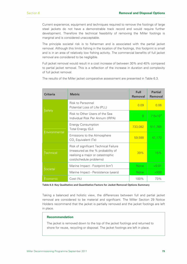
Section 6 Removal and Disposal Options
Miller Decommissioning Programme September 2011 73
Current experience, equipment and techniques required to remove the footings of large steel jackets do not have a demonstrable track record and would require further development. Therefore the technical feasibility of removing the Miller footings is marginal and is considered unacceptable.
The principle societal risk is to fisherman and is associated with the partial jacket removal. Although this limits fishing in the location of the footings, this footprint is small and is in an area of relatively low fishing activity. The commercial benefits of full jacket removal are considered to be negligible.
Full jacket removal would result in a cost increase of between 30% and 40% compared to partial jacket removal. This is a reflection of the increase in duration and complexity of full jacket removal.
The results of the Miller jacket comparative assessment are presented in Table 6.3.
Criteria Metric Full
Removal
Partial
Removal
Risk to Personnel Potential Loss of Life (PLL)
0.09 0.06
Safety Risk to Other Users of the Sea Individual Risk Per Annum (IRPA)
0 7.5x10⁻⁸
Energy Consumption Total Energy (GJ)
733,082 511,765
Environmental Emissions to the Atmosphere CO2 Equivalent (Te)
59,588 41,170
Technical
Risk of significant Technical Failure (measured as the % probability of realising a major or catastrophic cost/schedule problems)
39% 15%
Marine Impact - Footprint (km2) None <0.01 Societal
Marine Impact - Persistence (years) None >500
Economic Cost (%) 100% 73%
Table 6.3: Key Qualitative and Quantitative Factors for Jacket Removal Options Summary
Taking a balanced and holistic view, the differences between full and partial jacket removal are considered to be material and significant. The Miller Section 29 Notice Holders recommend that the jacket is partially removed and the jacket footings are left in place.
Recommendation
The jacket is removed down to the top of the jacket footings and returned to shore for reuse, recycling or disposal. The jacket footings are left in place.
Removal and Disposal Options Section 6
74 Miller Decommissioning Programme September 2011
6.5 Drilling Template Decommissioning
The Miller drilling template is integral to the jacket footings and is in part covered by drill cuttings. The top of template is approximately 3.5m above the seabed and approximately 1m below the centreline of the jacket base plan bracing. The drilling template is contained wholly within the footprint and the envelope of the jacket footings and does not protrude beyond any part of the footings.
Removal of the template would require clearing of the cuttings pile from around the template in order to gain access to the template piles and to confirm that the template is free from seabed debris. The four template piles would have to be cut, either internally or external, before the template is removed. Those well conductors with latching mechanisms would have to be removed together with the template increasing the potential dropped object risk.
There is no feasible means of removing the template without disturbing the jacket footings or the cuttings pile, creating technical risk, safety risk and environmental impact.
Recommendation
The drilling template is left in place.
6.6 Wells and Platform Conductors Decommissioning
Wells decommissioning did not commence until all opportunities for continued oil production and alternative uses in situ had been exhausted. Well decommissioning and conductor removal operations have been completed for Miller.
Refer to Section 8 for further details.
Status
The wells are plugged and abandoned. Removed items have been returned to shore for reuse, recycling or disposal.
6.7 Pipeline Spools, Umbilicals, SSIVs and Associated Items
Decommissioning of the pipelines is deferred to allow future reuse. The proposal for the pipelines will be addressed to DECC under the Interim Pipeline Regime (IPR). The IPR condition of the pipelines will not prejudice any further decommissioning solution or pose an increased risk to users of the sea.
To allow decommissioning of the platform and reduce any residual risk to users of the sea, the pipelines are to be disconnected and isolated at Miller and the pipeline spools, umbilicals, SSIVs and associated items removed.
Section 6 Removal and Disposal Options
Miller Decommissioning Programme September 2011 75
Recommendation
The pipelines are flushed clear of hydrocarbons and left in situ for possible future use. Pipeline spools, umbilicals, SSIVs and structures associated with platform removal activity are removed and returned to shore for reuse, recycling or disposal.
6.8 Cuttings Pile Decommissioning
The Miller cuttings pile has been assessed against Stage 1 of the OSPAR Management Regime for Offshore Cuttings Piles Recommendation 2006/5 [Ref 9]. The purpose of this Recommendation is to reduce the impacts of pollution by oil and / or other substances from cuttings piles to a level that is not significant. To determine significance, OSPAR have set thresholds for the rate of oil loss to the water column and persistence over the area of seabed contaminated.
Stage 1 involved the initial screening of the Miller pile using existing evidence (physical samples from the pile) deemed sufficient to carry out the process. The results were compared against the thresholds and found to be below them, ie 82% below the rate of oil loss threshold and 95% below the persistence threshold. The OSPAR Recommendation determines that where both the rate and persistence are below the thresholds no further action is necessary and the cuttings pile may be left in situ to degrade naturally.
Miller’s compliance with Stage 1 meant that a Stage 2 study, which includes the requirement to undertake a comparative assessment for removal or treatment, was not required.
Recommendation
The cuttings pile is left in situ to degrade and to allow the seabed to recover naturally.

Removal and Disposal Options Section 6
76 Miller Decommissioning Programme September 2011
I n t e n t i o n a l l y L e f t B l a n k

Section 7 Selected Removal and Disposal Option
Miller Decommissioning Programme September 2011 77
7 Selected Removal and Disposal Option
This section describes the selected removal and disposal option, the
decommissioning method and the disposal route for each element of the
Miller Decommissioning Programme.
7.1 Topsides Decommissioning
7.1.1 Introduction
Under the terms of OSPAR Decision 98/3 [Ref 4], there is a prohibition on the dumping and leaving wholly or partly in place of offshore Installations. Accordingly, the topsides of all Installations must be returned to shore for reuse, recycling or disposal. Studies carried out by the Miller Section 29 Notice Holders, and data from other decommissioning programmes, indicate that removal of the Miller topsides is technically feasible.
Therefore the Miller Section 29 Notice Holders’ recommendation is for complete removal of the topsides to shore for reuse, recycle or disposal. The Miller topsides has been subject to a continuous programme of structural integrity management. Structural analysis [Ref 41], [Ref 46] has confirmed that the topside components are capable of withstanding the operations required to bring them to shore for recycling. As discussed in Section 6.1, alternative use and reuse options for the topsides have been considered and discounted. Therefore, it is not necessary to consider alternative decommissioning options.
This section of the decommissioning programme describes in principle the activities required for decommissioning and disposal of the topsides modules.
7.1.2 Preparatory Work for Topsides Removal
Before any dismantling or removal option operations begin, it will be necessary to prepare the topsides to ensure that all safety and environmental risks are minimised, So Far As Is Reasonably Practicable (SFAIRP). This process involves topsides cleaning and engineering-down.
The cleaning programme is designed to remove SFAIRP all chemicals and hydrocarbons. The major steps involved in the cleaning operation would be:
(1) Removing all hydrocarbons, chemicals and residues SFAIRP from the production systems by purging and flushing into handling and export systems that are designed specifically to deal with these materials.
(2) Isolating equipment from all power and production inputs and outputs under the Permit to Work System, and ensuring that it is safe for human intervention.
(3) Opening systems and removing any remaining production residues, chemicals and other materials using specialised cleaning equipment and personnel, where required. Ensuring that all materials/residues are stored correctly and disposed of via the appropriate and approved disposal route.
Selected Removal and Disposal Option Section 7
78 Miller Decommissioning Programme September 2011
(4) On completion of the cleaning operations, tagging all systems and clearly identifying the plant condition.
(5) Carrying out independent inspections (by a competent Technical Authority) to confirm systems are cleaned and, where possible, identified as non-hazardous.
Engineering down is the de-energising of all plant equipment and systems, including positive isolation, and de-energising electrical, instrumentation and process systems to prevent possible injury to personnel during dismantling.
Once cleaning and engineering down is complete the topsides modules are prepare for removal. This requires a systematic programme of Module, Process and Utilities Separation (MPUS). Depending on the type of removal method that is adopted this scope of work could include some, or all of the following:
(1) Disconnecting piping, electrical wiring and other services that link the modules, or span the gap between the topsides modules, module support frame and jacket.
(2) Removing or cutting the pipeline risers and caissons.
(3) Separating the structural connections, walkways and stairs between the modules, module support frame and jacket.
(4) Adding additional strengthening or temporary reinforcement to modules, as required.
(5) Removing or securing items of loose equipment.
(6) Installing or reinstating lifting points on modules, as required.
7.1.3 Removal Methods
For the removal of the topsides there are a number of removal methods available to the Miller Section 29 Notice Holders. At the time of the development of this Decommissioning Programme, there have been a number of dismantlement projects which have removed the topsides utilising the reverse installation method using a Heavy Lift Vessel (HLV), eg North West Hutton [Ref 47] and offshore deconstruction, Ekofisk Tank Topsides.
Whereas the reverse installation method has been shown to be technically feasible and can be carried out safely, for the submission of this Decommissioning Programme the Miller Section 29 Notice Holders recognise that technology continues to advance and other methods may demonstrate technical feasibility and track record to allow consideration during the dismantling engineering and contracting phases of this project. For the purposes of this Decommissioning Programme three removal techniques are presented to describe the range of methods available to the Miller Section 29 Notice Holders, covering both existing and proven technologies and emerging technologies.
The methods considered within this Decommissioning Programme are:
Offshore Deconstruction
Reverse Installation using a HLV
Removal using a Single Lift Vessel (SLV)
The methods are summarised below.

Section 7 Selected Removal and Disposal Option
Miller Decommissioning Programme September 2011 79
Offshore Deconstruction
The Offshore Deconstruction of topsides modules is a proven method of dismantling topsides structures. Each module and its components are cut into small manageable pieces, using hydraulic shears and other cutting techniques. These pieces are removed using the platform cranes or temporary lifting devices and transported to shore on supply boats or transport barges. The process usually involves a small number of highly skilled operators working over a relatively long period of time.
Overall topsides structural integrity is dependant on the integrity of individual modules, so a progressive dismantling programme would have to be planned carefully to ensure overall structural integrity and safety of personnel. Therefore, some topsides modules are more conducive to this type of dismantling. The Miller topsides is not particularly well suited, because it is built up of a small number of large, discretely supported modules; progressive deconstruction would render large portions of the remnant structure unstable.
There is currently limited experience or proven procedures for using this method on a platform the size and complexity of Miller, therefore planning and executing the work would be a major challenge [Ref 35], [Ref 48]. The exposed location, restricted working space and congested nature of the platform means there are significant and as yet undefined safety risks to personnel due to the numerous cuts, material handling, working at heights and crane lifts that are associated with this method. There would also be significant helicopter and marine vessel movements, which are also high risk activities.
Reverse Installation using a Heavy Lift Vessel
This method requires the modules and other components that comprise the topsides to be separated and lifted from the platform using a HLV and is in essence a reverse of the original installation procedure. A large number of marine vessels would be required to be in attendance including tugs, cargo barges, anchor handling boats and offshore construction vessels.
Study work has demonstrated the technical feasibility of removing the modules using a HLV. Up to 12 heavy lifts would be required to remove the modules down to the Module Support Frame (MSF). Each module would constitute a separately engineered heavy lift. The existing module lift points would be used to attach slings and lifting apparatus to facilitate the lift. Offshore surveys would be required to confirm the integrity of these lift points and the module structure to ensure structural stability of the lift. In a few cases it might be necessary to add additional strengthening or reinforcement prior to removal.
New lifting points would have to be installed on the helideck, and tested prior to lifting operations [Ref 49].
The major steps involved in a reverse installation would be:
(1) Disconnecting the piping, electrical wiring and other services that link the modules.
(2) Removing or securing items of loose equipment.
(3) Removing or cutting the pipeline risers and caissons.
(4) Adding additional strengthening or reinforcement to modules, as required.
(5) Installing or reinstating lifting points on modules, as required.
Selected Removal and Disposal Option Section 7
80 Miller Decommissioning Programme September 2011
(6) Separating the structural connections, walkways and stairs between the modules.
(7) Lifting and securing the modules onto the HLV/transport barge.
(8) Transporting all modules to shore for dismantling.
The Reverse Installation method of removing topsides structures is relatively mature, with a well understood set of technical risks. There is a small number of specialist semi-submersible HLVs that can perform this operation. Given the size of the Miller modules, removal operations would be restricted to the summer time.
Removal using a Single Lift Vessel
Various concepts have been proposed for the complete removal of the Miller topsides using a specialist SLV. Single lift has the benefit of transferring a large offshore preparatory scope of work to a near-shore or even direct onshore location. Furthermore, potentially fewer personnel are involved in the offshore operation, thus reducing the offshore exposure hours. However, the technology is hugely demanding of the topsides, requiring the structure to undergo loading conditions it was never designed for.
Single lift technology is being developed but, at present, equipment is not available on the market to undertake a single lift of the Miller topsides. Furthermore, there is no track record for this method and there are a very limited number of onshore facilities that could accept such a large structure for subsequent dismantling. The technology can therefore be classified as being immature and unproven giving rise to a number of significant engineering challenges. The lack of documented experience, experienced personnel, and proven procedures, means that this method is considered a high technical risk with the high potential for cost and schedule overruns.
Given that the single lift method does offer potential advantages, including a significant reduction in the amount of preparatory work required offshore, the Miller Section 29 Notice Holders will continue to monitor the development of these technologies.
7.1.4 Onshore Disposal of Topsides
Objective
For the onshore treatment and disposal of Miller material, the objective of the Miller Section 29 Notice Holders is that the waste hierarchy will be applied, ie material will be reused and recycled wherever possible in preference to disposal. All waste materials will be transferred, treated or disposed of by licensed contractors at licensed sites with all the necessary permits, licences and consents. Throughout these activities ‘Duty of Care’ will be exercised through an appropriate assurance process.
To measure this objective the Miller Section 29 Notice Holders have set a target of 97% re-use or recycling of the recovered material to be achieved through contractual arrangements and other incentives to ensure that this figure is maximised.
On completion, the quantities of material, reused, recycled and disposed, the sites and methods used to dispose of hazardous waste, will be compiled for reporting.
Section 7 Selected Removal and Disposal Option
Miller Decommissioning Programme September 2011 81
Topsides Modules
The topsides modules were assembled from twelve individual modules, which are mostly externally trussed ‘box’ style structures. These modules contain different facilities such as an accommodation module, oil and gas production and processing equipment, power generation facilities, storage tanks for diesel fuel oil, potable water etc. Therefore, each module contains different materials depending on the type of facilities present. An inventory of these materials [Ref 6] has been compiled and is indicative of the materials expected after the topsides systems have been freed of gross hydrocarbons, chemicals and engineered down.
To make these systems free of gross hydrocarbons and chemicals, pipework and vessel inventories were emptied to either oil and gas export routes or containment, prior to re-injection into disposal wells or transfer to onshore for treatment or disposal. Once the inventories were removed the systems were flushed with seawater, engineered down and left vented to atmosphere. All of these activities were undertaken in accordance with the regulatory licences, permits and consents applicable to the offshore operations.
Naturally Occurring Radioactive Material (NORM)
The Miller Field has had a history of Naturally Occurring Radioactive Material (NORM) accumulating in the form of a mineral deposition of barium sulphate scale. The accumulation of this within the Miller topsides has historically been relatively high compared to a typical UK Continental Shelf Installation. Within the topsides facilities, NORM of varying activity is distributed predominately within the produced water system.
The separators and other vessels have historically been cleaned offshore under licence and during the engineering down phase these were cleaned of gross scale and sand.
There are a number of options both offshore and onshore for the disposal of NORM from the Miller platform but, prior to any disposal, the NORM has to be removed from the contaminated pipework, valves and equipment. An evaluation of these options recognised that 100% removal offshore would not be technically possible, due to accessibility and methods available to remove the NORM from systems, and that an onshore disposal option would always be required for residual scale.
All future handling, removal, treatment and disposal of NORM shall be undertaken by competent authorised contractors at licensed sites with all the necessary permits, licences and consents.
Onshore Disposal
The onshore location for receiving and dismantling of the topsides modules will not be selected until the engineering and contractual phase of the Decommissioning Programme. It is possible that more than one site would be used in the UK and abroad. The initial site(s) choice would be dependent on the selected removal method, but final selection would be subject to rigorous assessment and confirmation that all the necessary permits, procedures, competences and other requirements were in place.

Selected Removal and Disposal Option Section 7
82 Miller Decommissioning Programme September 2011
The current UK Management Plan for the Export and Import of Waste allows the export of material for the purpose of recovery. However, the Miller Section 29 Notice Holders have sought clarification on the fate of residual waste from recovery operations abroad from the Scottish Executive and was advised that agreement with Overseas Regulators should be sought to ensure that residual waste could be treated in the country of recovery operations. This has significant implications on any future contracting strategy if these regulatory agreements cannot be reached prior to award of contract.
There is also an expectation that any recovered NORM would be returned to the UK.
7.1.5 Topsides Removal Method Recommendation
The Reverse Installation method has been shown to be technically feasible. However, the Miller Section 29 Notice Holders recognise that technology continues to advance and other methods may demonstrate technical feasibility and a suitable track record to delivery to allow consideration during the dismantling engineering and contracting phases of the Miller Decommissioning Programme.
Therefore, whilst the Miller Section 29 Notice Holders are confident that the topsides can be removed to shore for recycling and disposal, no direct recommendation is made regarding the method of executing this outcome. The Miller Section 29 Notice Holders will undertake a robust contracting strategy to engage the suitable contractors to execute this scope of work, ensuring the work is carried out efficiently, safely and minimising environmental impacts.
7.2 Jacket Decommissioning
7.2.1 Introduction
Under the terms of OSPAR Decision 98/3 [Ref 4], there is a recognition of the difficulty of removing the footings of a large steel jacket. Through a process of comparative assessment, as described in Section 6 of this Decommissioning Programme, the Miller Section 29 Notice Holders recommend the removal of the Miller jacket leaving the footings in situ. This section of the decommissioning programme describes in principle the activities required for the removal and disposal of the Miller jacket.
7.2.2 Preparation for Removal
Removal of the jacket would require a diverse range of marine vessels and heavy plant similar to those that would be used for the removal of the topsides, with the additional need to coordinate subsea and surface activities.
It is assumed that the removal of the jacket would be undertaken as a separate activity from the removal of the topsides, possibly happening a full calendar year after completion of the topsides scope. This is to allow the jacket removal to be undertaken in the summer season when weather conditions would be more favourable. The condition of the jacket would need to be assessed prior to the start of the removal campaign, possibly through subsea survey work.
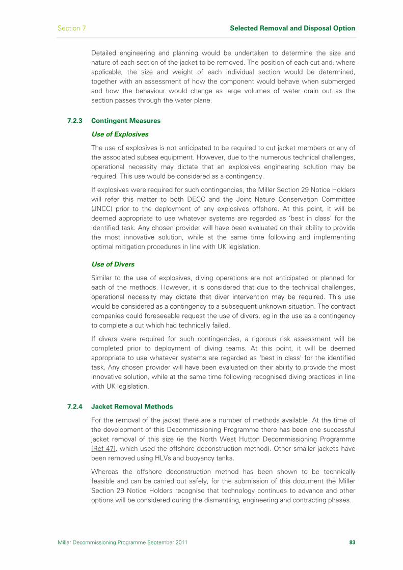
Section 7 Selected Removal and Disposal Option
Miller Decommissioning Programme September 2011 83
Detailed engineering and planning would be undertaken to determine the size and nature of each section of the jacket to be removed. The position of each cut and, where applicable, the size and weight of each individual section would be determined, together with an assessment of how the component would behave when submerged and how the behaviour would change as large volumes of water drain out as the section passes through the water plane.
7.2.3 Contingent Measures
Use of Explosives
The use of explosives is not anticipated to be required to cut jacket members or any of the associated subsea equipment. However, due to the numerous technical challenges, operational necessity may dictate that an explosives engineering solution may be required. This use would be considered as a contingency.
If explosives were required for such contingencies, the Miller Section 29 Notice Holders will refer this matter to both DECC and the Joint Nature Conservation Committee (JNCC) prior to the deployment of any explosives offshore. At this point, it will be deemed appropriate to use whatever systems are regarded as ‘best in class’ for the identified task. Any chosen provider will have been evaluated on their ability to provide the most innovative solution, while at the same time following and implementing optimal mitigation procedures in line with UK legislation.
Use of Divers
Similar to the use of explosives, diving operations are not anticipated or planned for each of the methods. However, it is considered that due to the technical challenges, operational necessity may dictate that diver intervention may be required. This use would be considered as a contingency to a subsequent unknown situation. The contract companies could foreseeable request the use of divers, eg in the use as a contingency to complete a cut which had technically failed.
If divers were required for such contingencies, a rigorous risk assessment will be completed prior to deployment of diving teams. At this point, it will be deemed appropriate to use whatever systems are regarded as ‘best in class’ for the identified task. Any chosen provider will have been evaluated on their ability to provide the most innovative solution, while at the same time following recognised diving practices in line with UK legislation.
7.2.4 Jacket Removal Methods
For the removal of the jacket there are a number of methods available. At the time of the development of this Decommissioning Programme there has been one successful jacket removal of this size (ie the North West Hutton Decommissioning Programme [Ref 47], which used the offshore deconstruction method). Other smaller jackets have been removed using HLVs and buoyancy tanks.
Whereas the offshore deconstruction method has been shown to be technically feasible and can be carried out safely, for the submission of this document the Miller Section 29 Notice Holders recognise that technology continues to advance and other options will be considered during the dismantling, engineering and contracting phases.

Selected Removal and Disposal Option Section 7
84 Miller Decommissioning Programme September 2011
The methods considered within the Miller Decommissioning Programme are:
Offshore Deconstruction
Float and Tow using buoyancy aids
Removal using a SLV
The methods are summarised below.
Offshore Deconstruction
Offshore Deconstruction involves subsea cutting of the jacket into a number of sections for transport to the onshore demolition yard for final disposal. Section 6, Figure 6.3 illustrates an example of how this can be achieved by lifting the sections out of the water using cranes attached to HLVs. The sections are then back-loaded onto a suitable transit vessel and transported to the onshore demolition yard.
Removal of the Miller jacket down to the top of the footings will require three or four major lifts, involving approximately 200 - 300 cuts. It is probable that the total number of cuts will be substantially higher due to the need to remove obstructions and potential dropped objects. Various studies have been carried out [Ref 32], [Ref 33] and predictions vary considerably for the number of sections and number of cuts required, due the various methods of dismantlement and the equipment available to each contractor. The number of sections and number of cuts required will not be finalised until detailed design for the removal phase.
It is probable that the required equipment will use existing technology. The cutting methods that are most likely to be deployed are diamond wire and Abrasive Water Jet (AWJ). Hydraulic shears could be used for members up to 1m diameter.
The diamond wire cutting method uses a strong wire with diamond beads along its length. The wire runs round a series of pulleys and is rotated very quickly, like a chain saw, to cut through steel members containing stiffening or pipe-work. AWJ cutting uses high-pressure water with entrained abrasive material to cut through members and is best suited to simple tubular components.
These two methods would be suitable for severing all members down to the top of the footings at 85m below sea level. The main risks are associated with the reliability of the cut, and the safe handling of the securing, cutting and rigging equipment (the rigging equipment alone can weigh up to 40 tonnes). The size and weight of the equipment that would have to be used presents two main problems; achieving safe access in and around the jacket structure, and positioning the unit to accurately cut the structural members.
Both the diamond wire and AWJ cutting techniques are prone to operational difficulties that can lead to incomplete cuts. For intermediate or preparatory cuts, this would probably result in the requirement to repeat the cut, and there would be no major impacts apart from time delay and additional cost. However, for the final three or four structural cuts required to free each section for lifting, failure to complete a cut would represent a major source of risk because the crane would be attached to the section in readiness to lift. A cutting failure at this stage could result in the equipment and vessels being exposed to a severe risk of damage due to loss of stability and integrity of the section being removed.

Section 7 Selected Removal and Disposal Option
Miller Decommissioning Programme September 2011 85
The contingencies to mitigate the consequences of a failed cutting operation are threefold:
The final cuts will not be started unless the weather window is long enough to allow time for repeat cuts
Spare cutting tools will be carried on the vessel
An alternative location will be prepared adjacent to the cut in case of total failure to separate the member
Development work will be required to design and manufacture clamps and rigging equipment with the size and capacity required for use on Miller. Lifting clamps would have to be attached subsea without a complete understanding of the section geometry or weight. The clamps operate on close tolerance and the activation of teeth to grip the steel as the method of attaching the rigging to the section being lifted. During lifting operations, any failure of the clamps or rigging equipment would result in the load being dropped onto the remainder of the jacket structure or, more significantly, onto the crane vessel or transport barge where personnel will be present. This is a risk in all construction lifts, but in a deconstruction operation such as that required for Miller, there would be more uncertainty, and this would increase the overall risk of a catastrophic failure. The experience and lessons learned from other Decommissioning Programmes will assist with the engineering.
Float and Tow Using Buoyancy Aids
Concepts are in development for the removal of jacket structures using large floatation tanks, secured to the jacket by a series of self-closing and hydraulically-actuated clamps. Marine tugs are used to transport the tanks to the offshore location and secure the tanks to the jacket corner legs. Once secured, the tanks are progressively de-ballasted until the required buoyancy force is generated and the jacket is refloated and lifted clear of the footings. The jacket is then towed to a sheltered, deepwater anchorage and set down in preparation for piece small destruction.
Float and Tow proposals require less work at the offshore location (where the environmental conditions are generally harsher) and more work at a near-shore location (where access is better and environmental conditions more benign). However, there are additional environmental sensitivities regards undertaking this type of work in near-shore locations.
In principle, Float and Tow is a very efficient means of removing the jacket. However, there are several technical uncertainties in using this method. Each tank is a complex and bespoke lifting device, requiring electrical control and hydraulic power from a remote location. Extensive preparatory work is required to demonstrate the integrity of the jacket structure to undergo a loading condition it was never designed for.
To date, only the Frigg DP2 jacket, weighing 8,500 tonnes, has been removed by Float and Tow. No jacket of the weight and dimensions of Miller has been removed using this method.

Selected Removal and Disposal Option Section 7
86 Miller Decommissioning Programme September 2011
Removal Using a Single Lift Vessel
Various concepts have been proposed for the complete removal of the Miller jacket using a specialist SLV. Single lift would entail using a purpose-built vessel (preferably capable of lifting the entire structure) to lift the jacket from the seabed and either transport it to shore or transfer it onto a cargo barge for transport to the dismantling site. SLVs vary in configuration from very large ship-shaped vessels, to smaller mono-hull units and twin-vessel configurations.
The single lift method does offer potential advantages, including a significant reduction in the amount of cutting and lifting work required offshore. This reduces a lot of the risk to offshore personnel, however, this risk is shifted inshore and onshore to where the jacket would eventually be dismantled.
It is necessary to consider the ability of the jacket to be lifted by such a method. During the removal, the jacket would have to withstand considerable dynamic forces due to the loading from raising the entire structure, wave and current action, and the motion of the vessels during transportation. However, there is no track record for this method of offshore decommissioning and there are a very limited number of onshore facilities that could accept such a large structure for subsequent dismantling. The technology can therefore be classified as being immature and unproven giving rise to a number of significant engineering challenges. The lack of documented experience, experienced personnel, and proven procedures, means that this method is considered a high technical risk with the high potential of cost and schedule overruns.
The industry recognises the potential importance of single lift techniques and a number of joint projects have been funded and carried out to develop the technology. At present, there are no single lift systems of sufficient capacity to undertake the single lift removal of the Miller jacket.
7.2.5 Onshore Disposal
The onshore disposal of the Miller jacket will follow the same waste management principles as described in Section 7.1.4.
There are a number of specific points relevant to the handling of the jacket as follows:
A site is required capable of handling large structures delivered in close succession, therefore requiring the necessary handling and storage facilities
For certain decommissioning methods, the receiving site must have deep water capacity to receive the structure, potentially as a single unit. Temporary inshore storage may also be required. The assumption is that the structure will have to remain vertical in the water, due to the technical complexity of ‘upending’ such a large structure. There may be a requirement to place such a large structure onto the seabed, during final dismantlement which in turn would create further disturbance to marine life. It is also expected that the techniques used for offshore deconstruction would then need to be used to reduce the structure to manageable pieces for lifting to shore. Environmentally there is a greater risk of transferring marine life to the location for dismantlement. At the present time there are no deep water sites with the necessary onshore support infrastructure identified in the UK
For the Single Lift method there are the added technical issues surrounding the removal of the jacket from the vessel, prior to final dismantlement

Section 7 Selected Removal and Disposal Option
Miller Decommissioning Programme September 2011 87
7.2.6 Jacket Removal Method Recommendation
The Miller Section 29 Notice Holders will continue to monitor the development of removal technologies and maintain dialogue with several contractors to keep abreast of emerging technologies.
Therefore, whilst the Miller Section 29 Notice Holders are confident that the jacket can be removed to shore for recycling and disposal using the offshore deconstruction method, no direct recommendation is made regarding the method of executing the jacket removal.
The Miller Section 29 Notice Holders will undertake a robust contracting strategy to engage suitable contractors to execute this scope of work, ensuring the work is carried out efficiently and safely, whilst minimising environmental impacts.
7.3 Wells and Platform Conductors Decommissioning
The recommendation in Section 6.6 is that the wells are plugged and abandoned. Removed items are returned to shore for reuse, recycling or disposal. Well decommissioning and conductor removal operations are expected to be completed in 2009. Refer to Section 8 for further details.
7.4 Pipeline Spools, Umbilicals, SSIVs and Associated Items
7.4.1 Introduction
The pipelines are suspended under the Disused Pipelines Notification (Interim Pipelines Regime) (IPR) and therefore not part of the Miller Decommissioning Programme submission. The IPR ensures that out of use pipelines do not pose a risk to other users of the sea or to the environment. To enable removal of the topsides and jacket it is necessary to disconnect the pipelines from the platform.
The recommendation in Section 6.7 is that the pipelines are flushed clear of hydrocarbons and left in situ for possible future use. Pipeline spools, umbilicals, SSIVs and structures associated with platform removal activity are removed and returned to shore for reuse, recycling or disposal.
7.4.2 30in Gas Export Pipeline (PL-720) Disconnection
At Miller, the spools between the riser and the SSIV, and between the SSIV and the pipeline will be disconnected and removed. The protection features will be removed from the SSIV control umbilical and the control umbilical will be removed between the jacket and the SSIV. The SSIV piles will be cut 3m below seabed and the SSIV removed.
Figure 7.1 shows the pipeline isolation point and the items to be recovered and returned to shore for recycling or disposal. The SSIV control umbilical is shown in Section 1, Figure 1.1.
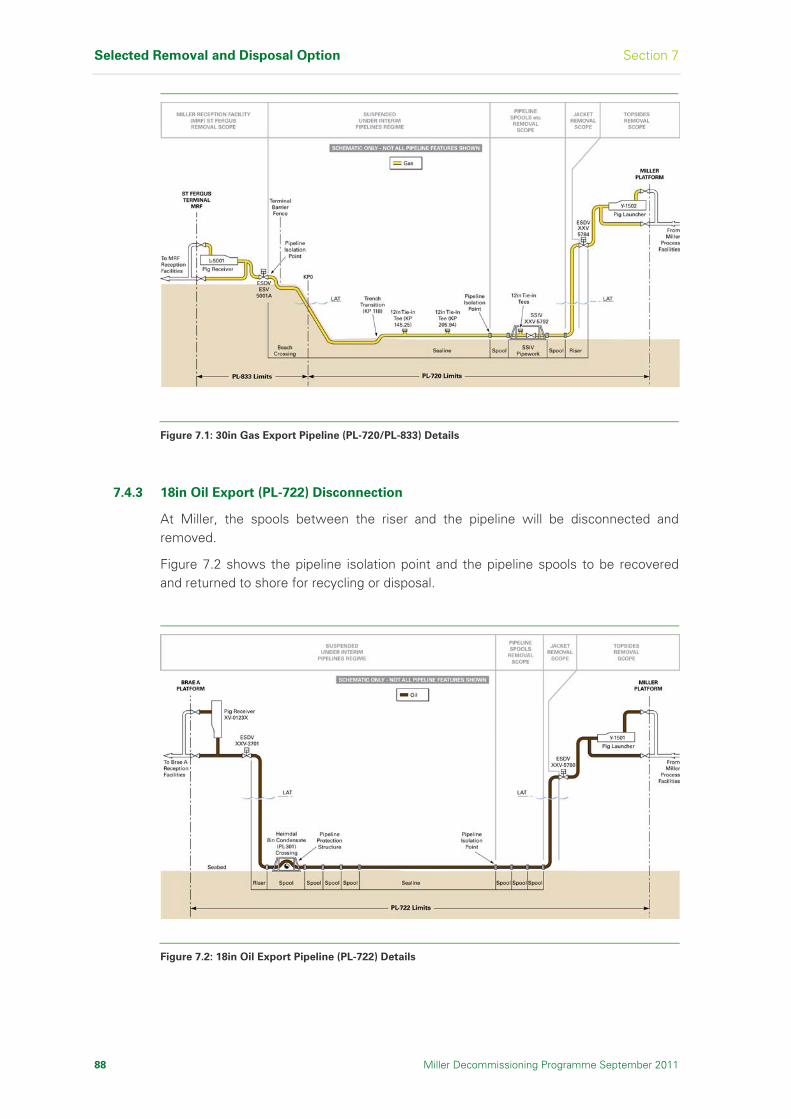
Selected Removal and Disposal Option Section 7
88 Miller Decommissioning Programme September 2011
Figure 7.1: 30in Gas Export Pipeline (PL-720/PL-833) Details
7.4.3 18in Oil Export (PL-722) Disconnection
At Miller, the spools between the riser and the pipeline will be disconnected and removed.
Figure 7.2 shows the pipeline isolation point and the pipeline spools to be recovered and returned to shore for recycling or disposal.
Figure 7.2: 18in Oil Export Pipeline (PL-722) Details

Section 7 Selected Removal and Disposal Option
7.4.4 16in Brae-Miller Linkline (PL-1971) Disconnection
At Miller, the spools between the riser and the SSIV, and between the SSIV and the pipeline will be disconnected and removed, and the control umbilical (PLU-1973) will be removed between the jacket and the SSIV. The SSIV will be removed. Protection features will be removed between the SSIV control umbilical and the spools.
Figure 7.3 shows the pipeline isolation point and the items to be recovered and returned to shore for recycling or disposal. The SSIV control umbilical is shown in Section 1, Figure 1.3.
Miller Decommissioning Programme September 2011 89
Figure 7.3: 16in Brae-Miller Linkline (PL-1971) Details
7.4.5 Scope of Work
Disconnecting the pipelines can be carried out separately from other decommissioning activities. However, given the extent of activity and number of vessels required, coordination between activities is important.
The major pipeline activity, debris clearance and site survey work is planned to take place after the removal of the Miller topsides. The pipelines will not deteriorate in the short-term, which removes concerns about pipeline condition and integrity.
The major steps involved in pipeline disconnection would be:
(1) Performing a pre-disconnection underwater survey of the pipelines and associated items on the seabed.
(2) Re-positioning concrete mattresses at pipeline isolation ends.
(3) Removing the 30in gas export pipeline (PL-720) and 16in Brae-Miller Linkline (PL-1971) SSIVs, umbilicals and protection frames.
(4) Removing pipeline spools.
(5) Removing protection features.

Selected Removal and Disposal Option Section 7
90 Miller Decommissioning Programme September 2011
(6) Implementing the Integrity Management Programme to maintain the pipelines for potential future reuse.
7.4.6 Monitoring Programme for Material Left on Seabed
The remaining pipelines and risers have been, and continue to be, inspected and maintained under the Pipeline Integrity Management Scheme (PIMS) and platform Inspection and Maintenance Routines (IMRs) respectively.
A revised Integrity Management Programme is to be developed for the period after disconnection of the pipelines.
7.5 Cuttings Pile Decommissioning
The Miller cuttings pile has been assessed against the OSPAR Recommendation 2006/5 [Ref 9] and is in compliance with Stage 1 of the Cuttings Pile Management Regime, ie both the rate of oil loss to water column and persistence over the area of seabed contaminated are below the OSPAR thresholds and no other discharges have contaminated the cuttings pile.
Therefore, no further action is necessary and it is proposed that the cuttings pile is left in situ to degrade and to allow the seabed to recover naturally.

Section 8 Wells
Miller Decommissioning Programme September 2011 91
8 Wells
This section describes the abandonment operations carried out and the
final condition at the end of the well abandonment and conductor removal
phases of the wells on the Miller platform. Of the original 22 wells, seven
were drilled from the subsea drilling template, known as tieback wells and
the remaining fifteen were drilled from the platform (known as platform
wells).
8.1 Introduction
Wells decommissioning did not commence until all opportunities for continued oil production and alternative uses in situ had been exhausted.
Adherence to the Oil & Gas UK (OGUK) Guidelines for the Suspension and Abandonment of Wells, and the BP Drilling and Well Operations Policy ensure that wells are designed, drilled, maintained and abandoned to high, consistent standards.
Both the OGUK Guidelines and BP Drilling and Well Operations Policy agree that:
All wells are to be left in a condition such that leakage of formation fluid to surface will be adequately prevented
Cement is the prime material for abandonment purposes
Using these guidelines and policy, a suitable plugging strategy was proposed.
The Miller wells were abandoned in two phases using the Miller drill rig and existing drilling facilities, supplemented by coiled tubing equipment.
Details of the wells are listed in Table 8.1.
8.2 Well Abandonment and Conductor Removal
Although well abandonment is covered by a separate approval process, it is also an integral part of the Miller Decommissioning Programme.
The aims of the Well Decommissioning Programme were to:
Permanently and securely isolate and seal all hydrocarbons and other pressured formations
Remove all equipment down to 3m below the seabed
Miller well pre-abandonment operations commenced in early December 2007 and included drift runs to ascertain through bore, pressure and temperature data acquisition, installation of mechanical plug to isolate reservoir, punching of tubing above plug and circulation of both tubing and ‘A’ annulus to treated seawater. These operations helped define the final well abandonment method, which was through tubing, either by bullhead / circulation or by coiled tubing.

Wells Section 8
92 Miller Decommissioning Programme September 2011
Well
No
Slot
No Type of Well
Platform/
Pre-drilled Well
Well Abandonment
Report No Plug Status
A02 26 Alternative Gas/Seawater Injector
Pre-drilled 16/8-A02 3 Cement plugs installed
A03 16 Alternative Gas/Seawater Injector
Pre-drilled 16/8-A03 3 Cement plugs installed
A04 25 Alternative Gas/Seawater Injector
Pre-drilled 16/8-A04 3 Cement plugs installed
A05 37 Cutting Reinjection Pre-drilled 16/8-A05 3 Cement plugs installed
A06 34 Water Injector Pre-drilled 16/8-A06 3 Cement plugs installed
A07 27 Water Injector Pre-drilled 16/8-A07 3 Cement plugs installed
A08 40 Gas-Lift Producer Platform 16/8-A08 3 Cement plugs installed
A10 12 Water Injector Platform 16/8-A10 3 Cement plugs installed
A11 20 Water Injector Platform 16/8-A11 3 Cement plugs installed
A12 23 Producer Platform 16/8-A12 3 Cement plugs installed
A13 38 Cuttings Reinjection Platform 16/8-A13 3 Cement plugs installed
A14 19 Producer Platform 16/8-A14 3 Cement plugs installed
A16 01 Gas-Lift Producer Platform 16/8-A16 3 Cement plugs installed
A17 04 Producer Platform 16/8-A17 3 Cement plugs installed
A18 32 Gas Lift Producer Platform 16/8-A18 3 Cement plugs installed
A20 03 Producer Platform 16/8-A20 3 Cement plugs installed
A21 02 Gas Lift Producer Platform 16/8-A21 3 Cement plugs installed
A22 15 Alternative Gas/Seawater Injector
Pre-drilled 16/8-A22 3 Cement plugs installed
A23 13 Gas-Lift Producer Platform 16/8-A23 3 Cement plugs installed
A24 09 Producer Platform 16/8-A24 3 Cement plugs installed
A25 29 Gas-Lift Producer Platform 16/8-A25 3 Cement plugs installed
A26 08 Producer Platform 16/08-A26 3 Cement plugs installed
Table 8.1: Miller Wells Status

Section 8 Wells
Miller Decommissioning Programme September 2011 93
Phase 1 – Well Isolation
Reservoir isolation was effected by the placement of separate cement plus, as shown in Figure 8.1. Cement plug placement was through tubing within the cased hole. Due to the presence of deep control lines, the production tubing was recovered from slots 38, 13, 29, 23, 26, 08 and 27. Plug placement was effected by a combination of bullhead / circulation and coiled tubing. Plugs were placed to seal off the reservoir and isolate movable fluids from the surface. For the Miller reservoir, isolation consisted of three primary plugs.
Phase 2 – Recovery of Tubing, Casing and Conductors
The conductors were removed to 3m below the seabed except on the seven pre-drilled wells which, because of their design, it was not possible to retrieve from the drilling template. So these wells were cut as close as possible to the subsea wellhead, approximately 22ft above the seabed.
Details of the final status of the wells was included in the well abandonment reports, which will be available for review at BP and at the National Hydrocarbons Data Archive. The final status was notified to the DECC and other notifiable bodies as per the Miller licence, upon completion of abandonment activity.
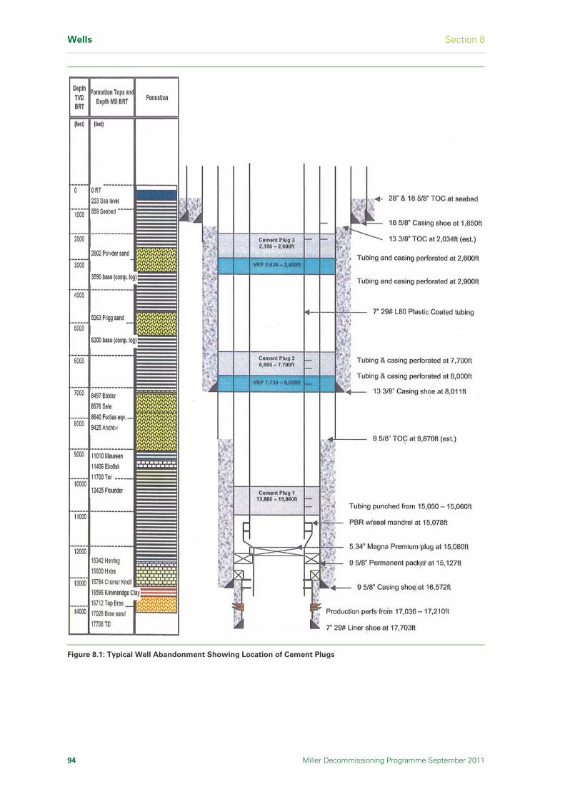
Wells Section 8
94 Miller Decommissioning Programme September 2011
Figure 8.1: Typical Well Abandonment Showing Location of Cement Plugs
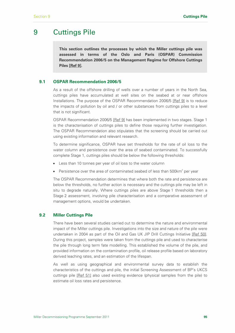
Section 9 Cuttings Pile
Miller Decommissioning Programme September 2011 95
9 Cuttings Pile
This section outlines the processes by which the Miller cuttings pile was
assessed in terms of the Oslo and Paris (OSPAR) Commission
Recommendation 2006/5 on the Management Regime for Offshore Cuttings
Piles [Ref 9].
9.1 OSPAR Recommendation 2006/5
As a result of the offshore drilling of wells over a number of years in the North Sea, cuttings piles have accumulated at well sites on the seabed at or near offshore Installations. The purpose of the OSPAR Recommendation 2006/5 [Ref 9] is to reduce the impacts of pollution by oil and / or other substances from cuttings piles to a level that is not significant.
OSPAR Recommendation 2006/5 [Ref 9] has been implemented in two stages. Stage 1 is the characterisation of cuttings piles to define those requiring further investigation. The OSPAR Recommendation also stipulates that the screening should be carried out using existing information and relevant research.
To determine significance, OSPAR have set thresholds for the rate of oil loss to the water column and persistence over the area of seabed contaminated. To successfully complete Stage 1, cuttings piles should be below the following thresholds:
Less than 10 tonnes per year of oil loss to the water column
Persistence over the area of contaminated seabed of less than 500km2 per year
The OSPAR Recommendation determines that where both the rate and persistence are below the thresholds, no further action is necessary and the cuttings pile may be left in situ to degrade naturally. Where cuttings piles are above Stage 1 thresholds then a Stage 2 assessment, involving pile characterisation and a comparative assessment of management options, would be undertaken.
9.2 Miller Cuttings Pile
There have been several studies carried out to determine the nature and environmental impact of the Miller cuttings pile. Investigations into the size and nature of the pile were undertaken in 2004 as part of the Oil and Gas UK JIP Drill Cuttings Initiative [Ref 50]. During this project, samples were taken from the cuttings pile and used to characterise the pile through long term fate modelling. This established the volume of the pile, and provided information on the contamination profile, oil release profile based on laboratory derived leaching rates, and an estimation of the lifespan.
As well as using geographical and environmental survey data to establish the characteristics of the cuttings and pile, the initial Screening Assessment of BP’s UKCS cuttings pile [Ref 51] also used existing evidence (physical samples from the pile) to estimate oil loss rates and persistence.
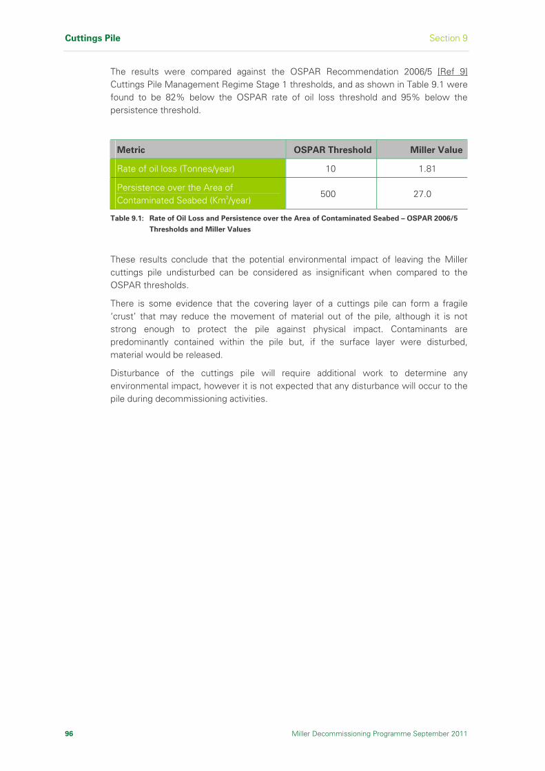
Cuttings Pile Section 9
96 Miller Decommissioning Programme September 2011
The results were compared against the OSPAR Recommendation 2006/5 [Ref 9] Cuttings Pile Management Regime Stage 1 thresholds, and as shown in Table 9.1 were found to be 82% below the OSPAR rate of oil loss threshold and 95% below the persistence threshold.
Metric OSPAR Threshold Miller Value
Rate of oil loss (Tonnes/year) 10 1.81
Persistence over the Area of Contaminated Seabed (Km2/year)
500 27.0
Table 9.1: Rate of Oil Loss and Persistence over the Area of Contaminated Seabed – OSPAR 2006/5
Thresholds and Miller Values
These results conclude that the potential environmental impact of leaving the Miller cuttings pile undisturbed can be considered as insignificant when compared to the OSPAR thresholds.
There is some evidence that the covering layer of a cuttings pile can form a fragile ‘crust’ that may reduce the movement of material out of the pile, although it is not strong enough to protect the pile against physical impact. Contaminants are predominantly contained within the pile but, if the surface layer were disturbed, material would be released.
Disturbance of the cuttings pile will require additional work to determine any environmental impact, however it is not expected that any disturbance will occur to the pile during decommissioning activities.
Section 10 Environmental Impact Assessment
Miller Decommissioning Programme September 2011 97
10 Environmental Impact Assessment
This section summarises the Environmental Impact Assessment
undertaken for the items to be decommissioned as described in Section 4,
and for the removal options and methods described in Sections 6 and 7.
10.1 Introduction
The Environmental Impact Assessment (EIA) [Ref 29] scope included the identification and evaluation of the impacts associated with all decommissioning activities at the Miller Field, undertaken by existing technology. Consideration was also given to new decommissioning technologies and, although none of these technologies are currently available, this does not preclude them being considered in this EIA. A generic assessment was undertaken for an inshore / onshore dismantling and disposal site as the exact location is unknown at this stage.
The EIA [Ref 29] identified and evaluated the potential environmental impacts to provide an understanding of their associated effects in order to compare the different options and removal methods that had been considered and to develop mitigation options.
10.2 Environmental Description
10.2.1 Hydrography
Bathymetry
The water depth at Miller is 103m. The platform is situated within the Witch Ground Basin, a relatively deep part of the Central North Sea where water depths range between 100 - 130m compared to the average range of 80 - 100m.
Current Regime
As shown in Figure 10.1, the predominant current in the vicinity of Miller is the Fair Isle/Dooley Current which flows south from Orkney until it reaches a depth of 100m, where it turns north-east and circulates in the Northern North Sea.
The second current influencing the area is the East Shetland Atlantic Inflow that flows to the north of the Fair Isle/Dooley current. The Dooley Current guides most of the water eastwards to the Norwegian trench along the 100m depth contour. Only a small part flows southward along the coast of Scotland and England [Ref 52]. During the winter months circulation is predominantly wind-driven, but during the summer, once vertical stratification begins to occur, it becomes increasingly density driven [Ref 53].
Surface water speeds in the vicinity of Miller are usually less than 0.84m/s and the residual water movement at sea is generally variable and wind driven [Ref 54]. Residual current speed declines with depth, with seabed currents at the Miller Field generally less than 0.43m/s.
A maximum tidal range of 1.5m is seen at Miller, compared to a tidal range of 2.5m in inshore waters. Tidal current speeds in the vicinity are approximately 0.26m/s.
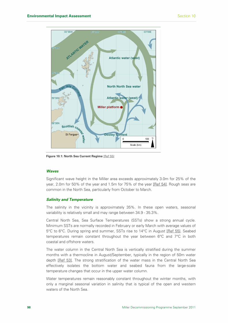
Environmental Impact Assessment Section 10
98 Miller Decommissioning Programme September 2011
Figure 10.1: North Sea Current Regime [Ref 55]
Waves
Significant wave height in the Miller area exceeds approximately 3.0m for 25% of the year, 2.0m for 50% of the year and 1.5m for 75% of the year [Ref 54]. Rough seas are common in the North Sea, particularly from October to March.
Salinity and Temperature
The salinity in the vicinity is approximately 35%. In these open waters, seasonal variability is relatively small and may range between 34.9 - 35.3%.
Central North Sea, Sea Surface Temperatures (SSTs) show a strong annual cycle. Minimum SSTs are normally recorded in February or early March with average values of 5°C to 6°C. During spring and summer, SSTs rise to 14°C in August [Ref 55]. Seabed temperatures remain constant throughout the year between 6°C and 7°C in both coastal and offshore waters.
The water column in the Central North Sea is vertically stratified during the summer months with a thermocline in August/September, typically in the region of 50m water depth [Ref 53]. The strong stratification of the water mass in the Central North Sea effectively isolates the bottom water and seabed fauna from the large-scale temperature changes that occur in the upper water column.
Water temperatures remain reasonably constant throughout the winter months, with only a marginal seasonal variation in salinity that is typical of the open and western waters of the North Sea.
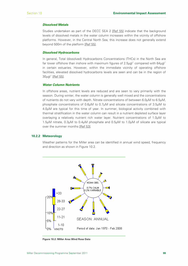
Section 10 Environmental Impact Assessment
Dissolved Metals
Studies undertaken as part of the DECC SEA 2 [Ref 55] indicate that the background levels of dissolved metals in the water column increases within the vicinity of offshore platforms. However, in the Central North Sea, this increase does not generally extend beyond 500m of the platform [Ref 55].
Dissolved Hydrocarbons
In general, Total (dissolved) Hydrocarbons Concentrations (THCs) in the North Sea are far lower offshore than inshore with maximum figures of 2.5µgl-1 compared with 64µgl-1 in certain estuaries. However, within the immediate vicinity of operating offshore facilities, elevated dissolved hydrocarbons levels are seen and can be in the region of 30µgl-1 [Ref 55].
Water Column Nutrients
In offshore areas, nutrient levels are reduced and are seen to vary primarily with the season. During winter, the water column is generally well mixed and the concentrations of nutrients do not vary with depth. Nitrate concentrations of between 6.0µM to 6.5µM, phosphate concentrations of 0.6µM to 0.7µM and silicate concentrations of 3.5µM to 4.0µM are typical for this time of year. In summer, biological activity combined with thermal stratification in the water column can result in a nutrient depleted surface layer overlaying a relatively nutrient rich water layer. Nutrient concentrations of 1.0µM to 1.5µM nitrate, 0.3µM to 0.4µM phosphate and 0.5µM to 1.0µM of silicate are typical over the summer months [Ref 53].
10.2.2 Meteorology
Weather patterns for the Miller area can be identified in annual wind speed, frequency and direction as shown in Figure 10.2.
Figure 10.2: Miller Area Wind Rose Data
Miller Decommissioning Programme September 2011 99
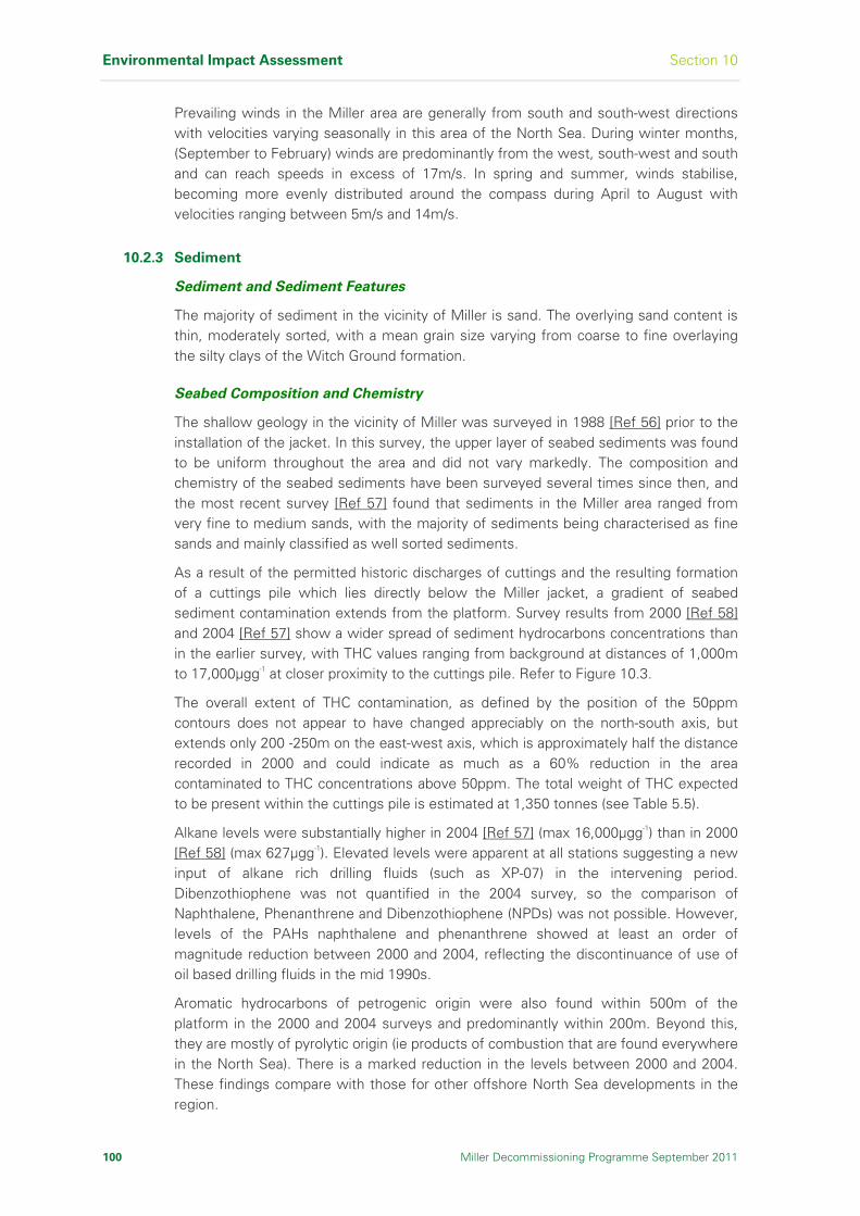
Environmental Impact Assessment Section 10
100 Miller Decommissioning Programme September 2011
Prevailing winds in the Miller area are generally from south and south-west directions with velocities varying seasonally in this area of the North Sea. During winter months, (September to February) winds are predominantly from the west, south-west and south and can reach speeds in excess of 17m/s. In spring and summer, winds stabilise, becoming more evenly distributed around the compass during April to August with velocities ranging between 5m/s and 14m/s.
10.2.3 Sediment
Sediment and Sediment Features
The majority of sediment in the vicinity of Miller is sand. The overlying sand content is thin, moderately sorted, with a mean grain size varying from coarse to fine overlaying the silty clays of the Witch Ground formation.
Seabed Composition and Chemistry
The shallow geology in the vicinity of Miller was surveyed in 1988 [Ref 56] prior to the installation of the jacket. In this survey, the upper layer of seabed sediments was found to be uniform throughout the area and did not vary markedly. The composition and chemistry of the seabed sediments have been surveyed several times since then, and the most recent survey [Ref 57] found that sediments in the Miller area ranged from very fine to medium sands, with the majority of sediments being characterised as fine sands and mainly classified as well sorted sediments.
As a result of the permitted historic discharges of cuttings and the resulting formation of a cuttings pile which lies directly below the Miller jacket, a gradient of seabed sediment contamination extends from the platform. Survey results from 2000 [Ref 58] and 2004 [Ref 57] show a wider spread of sediment hydrocarbons concentrations than in the earlier survey, with THC values ranging from background at distances of 1,000m to 17,000µgg-1 at closer proximity to the cuttings pile. Refer to Figure 10.3.
The overall extent of THC contamination, as defined by the position of the 50ppm contours does not appear to have changed appreciably on the north-south axis, but extends only 200 -250m on the east-west axis, which is approximately half the distance recorded in 2000 and could indicate as much as a 60% reduction in the area contaminated to THC concentrations above 50ppm. The total weight of THC expected to be present within the cuttings pile is estimated at 1,350 tonnes (see Table 5.5).
Alkane levels were substantially higher in 2004 [Ref 57] (max 16,000µgg-1) than in 2000 [Ref 58] (max 627µgg-1). Elevated levels were apparent at all stations suggesting a new input of alkane rich drilling fluids (such as XP-07) in the intervening period. Dibenzothiophene was not quantified in the 2004 survey, so the comparison of Naphthalene, Phenanthrene and Dibenzothiophene (NPDs) was not possible. However, levels of the PAHs naphthalene and phenanthrene showed at least an order of magnitude reduction between 2000 and 2004, reflecting the discontinuance of use of oil based drilling fluids in the mid 1990s.
Aromatic hydrocarbons of petrogenic origin were also found within 500m of the platform in the 2000 and 2004 surveys and predominantly within 200m. Beyond this, they are mostly of pyrolytic origin (ie products of combustion that are found everywhere in the North Sea). There is a marked reduction in the levels between 2000 and 2004. These findings compare with those for other offshore North Sea developments in the region.

Section 10 Environmental Impact Assessment
Miller Decommissioning Programme September 2011 101
Figure 10.3: Miller Cuttings Pile Bathymetry
The highest metal concentrations were found within 200m of the platform associated with the cuttings pile, with levels of contamination comparable to other North Sea platforms. Among the trace metals of environmental concern that showed increased levels in the cuttings pile is mercury, but there is no evidence of higher contamination of metals deeper into the pile.
A worst-case 0.04 tonnes of mercury are estimated to be present within the cuttings pile (see Table 5.5). Levels of barium were found to be lower in 2004 [Ref 57] compared with 2000 [Ref 58].
Contour plots of barium distribution in 2004 show that the main area of barium distribution beyond the immediate vicinity of the cuttings pile is to the north of the Installation indicating a continuing degree of dispersion in line with water currents.
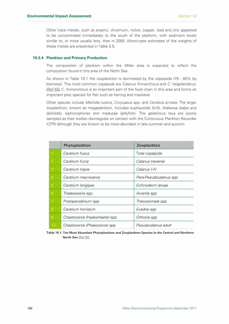
Environmental Impact Assessment Section 10
102 Miller Decommissioning Programme September 2011
Other trace metals, such as arsenic, chromium, nickel, copper, lead and zinc appeared to be concentrated immediately to the south of the platform, with sediment levels similar to, or more usually less, than in 2000. Worst-case estimates of the weights of these metals are presented in Table 5.5.
10.2.4 Plankton and Primary Production
The composition of plankton within the Miller area is expected to reflect the composition found in this area of the North Sea.
As shown in Table 10.1 the zooplankton is dominated by the copepods (70 - 80% by biomass). The most common copepods are Calanus finmarchicus and C. helgolandicus. [Ref 55] C. finmarchicus is an important part of the food chain in this area and forms an important prey species for fish such as herring and mackerel.
Other species include Metridia lucens, Corycaeus spp. and Candicia armata. The larger zooplankton, known as megaplankton, includes euphausiids (krill), thaliacea (salps and doliolids), siphonophores and medusae (jellyfish). The gelatinous taxa are poorly sampled as their bodies disintegrate on contact with the Continuous Plankton Recorder (CPR) although they are known to be more abundant in late summer and autumn.
Phytoplankton Zooplankton
1 Ceratium fusus Total copepods
2 Ceratium furca Calanus traverse
3 Ceratium tripos Calanus I-IV
4 Ceratium macroceros Para-Pseudocalanus spp
5 Ceratium longipes Echinoderm larvae
6 Thalassiosira spp. Arcartia spp
7 Protoperodinium spp. Thecosomata spp
8 Ceratium horridum Evadne spp
9 Chaetoceros (Hyalochaete) spp. Oithona spp
10 Chaetoceros (Phaeoceros) spp. Pseudocalanus adult
Table 10.1: Ten Most Abundant Phytoplankton and Zooplankton Species in the Central and Northern
North Sea [Ref 55]
Section 10 Environmental Impact Assessment
Miller Decommissioning Programme September 2011 103
10.2.5 Seabed and Benthic Communities
The benthic communities in the region of Miller comprise typically of the deeper water sand communities. The seabed fauna in this area are generally regarded as uniform with moderate species richness and faunal densities, and with moderately high productivity but low biomass. The low biomass may in part be an artefact of inadequate sampling of deep burrowing species such as Nephrops and Calocarius and the Hagfish Myxine which, although contributing substantial biomass, are generally poorly sampled by grab and core samplers [Ref 55]. This results in the presence of a modified benthic invertebrate community within samples.
Benthic Communities in the Vicinity of Miller
In a seabed baseline survey [Ref 56] carried out by BP in 1988 (prior to any drilling activity), univariate and multivariate analyses of the faunal data indicated that there were no environmental gradients in the survey area that could be related to offshore industrial activity. In the 2000 survey [Ref 58], there was a clear gradient of species richness with the lowest values at the stations closest to the platform.
The environmental seabed survey [Ref 58] was undertaken in July 2000 in the area of the Miller Field development, within and beyond the 500m zone. A total of 15 locations were sampled along two transects bisecting the Miller location. Overall, 234 taxa were identified from the 30 samples that were analysed.
Opportunistic species such as Capitella capitata and Ophryotrocha spp., that are associated with organic enrichment, dominated the benthos at stations closest to the platform. The macrofauna was composed of annelids (49.3%), arthropods (23%), molluscs (17.6%), echinoderms (3.1%) and minor phyla (6.2%). This is considered to be relatively typical of macrobenthic communities in offshore sediments for this area of the North Sea, where polychaetes have been found to account for approximately 50% of the species encountered [Ref 58]. Common taxa included the polychaetes Paramphinome jeffreysii, Pholoe assimilis, Aphelochaeta spp, Exogone veruger, Spiophanes kroyeri and Jasmineira caudata. Opisthobranch molluscs belonging to the order Cephalaspedia (including Cylichna cylindracea, Philine quadrata, P. scabra and Refusa umbilicata), the bivalve mollusc Thyasira pygmaea and Nemertean worms were also found to be consistently common. Species richness, animal density and community diversity of benthic assemblages were within the ranges previously reported for this area [Ref 58].
The biological effects of drilling activities, as indicated by species richness, diversity and multivariate analysis of the species associations, extended out to 500m from the platform. Benthic Habitat Quality (BHQ) measures at 100m and 250m south of the platform show that at the time of the 2000 survey [Ref 58] the seabed environment was grossly affected by the close proximity of the cuttings pile.
It is not possible to establish the degree of environmental recovery that might have taken place without a measure of the status of the environment at the peak of drilling activity. The 2000 survey [Ref 58] did however indicate a limited extent of contamination and its associated environmental impact suggest that the seabed around Miller may have undergone some degree of rehabilitation since drill cuttings have been routinely re-injected [Ref 58], [Ref 59] compared to the background levels outwith the platform 500m zone.

Environmental Impact Assessment Section 10
104 Miller Decommissioning Programme September 2011
10.2.6 Fish Populations
Demersal and pelagic species dominate the offshore waters, whilst shellfish species are concentrated on the coast. The exception is the Norwegian lobster (Nephrops norvegicus). These burrowing animals inhabit the muddy sediments found throughout the northern and central North Sea.
Fish and shellfish populations are vulnerable to impacts from offshore installations, such as hydrocarbons pollution and exposure to aqueous effluents (especially during the egg and juvenile stages of their lifecycles). The eggs of certain species, develop on the seabed and could be susceptible to smothering by discharged solids or disturbed sediments.
10.2.7 Spawning and Nursery Areas
Four species are known to use the area around Miller as spawning and/or nursery grounds, as shown in Figure 10.4. These are the Norway pout, Nephrops, haddock and blue whiting [Ref 44], [Ref 60].
Figure 10.4: Spawning and Nursery Grounds around Miller [Ref 44]
Section 10 Environmental Impact Assessment
Miller Decommissioning Programme September 2011 105
Norway pout are generally found in large schools within a few metres of the sea surface in the northern and central areas of the North Sea. Peak spawning activity occurs during February and March, but also occurs slightly later between March and May in deeper parts of the North Sea. Norway pout do not have specific nursery grounds, but are widely dispersed in the Northern North Sea in close proximity to their spawning grounds.
Nephrops spend most of their lives in one area and do not migrate from their burrows [Ref 60]. This species spawns in the sediments characteristic of the seabed around Miller and is one of the main species targeted by the fishing industry in the area [Ref 44].
The extensive nursery grounds for Haddock and Blue Whiting include the Miller area though neither of these species spawn in this area.
10.2.8 Seabirds
Within the vicinity of Miller a number of species are encountered at various times of the year. The main species likely to be encountered are auks - guillemot (Cephus grille) Atlantic puffin (Fratercula arctica) and razorbill (Alca torda) – northern fulmar (Fulmarus glacialis), northern gannet (Sula bassana), and kittiwake (Larus tridactyla). Other species that can be expected to occur in the area in lower numbers include, little auk (Alle alle), black-backed gull (Larus marinus), herring gull (Larus argentatus), lesser black-backed gull (Larus fuscus), great skua (Catharcta skua), Arctic skua (Stercorarius parasiticus), and storm petrel (Hydrobates pelagicus).
After the breeding season ends in June, large numbers of moulting auks with young disperse widely away from their coastal colonies and into offshore waters from July onwards. At this time, these birds are particularly vulnerable to oil pollution. In addition to auks, kittiwake, gannet and fulmar are present in sizeable numbers during the post-breeding season.
The main potential risk to birds is from surface oil pollution, which can cause direct toxicity through ingestion, and hypothermia as a result of a bird’s inability to waterproof their feathers should they become covered with oil. Due to differences in behaviour and distribution, the threat from hydrocarbons pollution varies with species.
Species such as guillemots are at high risk from surface pollutants because they spend much of their time on the sea surface. Several species undergo a total moult of their flight feathers at some point during the year, during which they cannot fly. These birds are therefore confined to the sea surface during this time, and this significantly increases their vulnerability to oil pollution (eg auks and Atlantic puffin).
The seasonal vulnerability of seabirds to oil pollution within the vicinity of Miller is presented in Figure 10.5. This suggests that seabird vulnerability to oil pollution will be high in January, February, April, possibly May (data is lacking but suggested by adjacent blocks), July, October and November. November is of notably high vulnerability with several blocks adjacent to Miller having very high vulnerability scores.

Environmental Impact Assessment Section 10
106 Miller Decommissioning Programme September 2011
Figure 10.5: Block Specific Seabird Vulnerability to Surface Pollution around the Miller Platform and
Surrounding Area [Ref 61]

Section 10 Environmental Impact Assessment
10.2.9 Marine Mammals
Ten cetacean species have been recorded in the Central North Sea, minke whale (Balaenoptera acutorostrata), white-beaked dolphin (Lagenorhynchus albirostris), Atlantic white-sided dolphin (Lagenorhynchus acutus), harbour porpoise (Phocoena phocoena), Risso’s Dolphin (Grampus griseus), Killer whale (Orcinus orca), Humpback whale (Megaptera novaeangliae), Pygmy sperm whale (Kogia brevicep), Common bottlenose dolphin (Tursiops truncates) and Short-beaked common dolphin (Delphinus delphis) [Ref 62]. Of these, Minke Whale, White Sided Dolphin and White beaked dolphin have been sighted within the vicinity of the Miller Platform, as shown in Figure 10.6.
Figure 10.6: Location of Cetacean Sightings in the Vicinity of the Miller Platform (2005) [Ref 62]
Animal population and density estimates for the wider Miller area, suggest that the most likely animal to be encountered will be the harbour porpoise (0.294 animals/km2) and the least likely will be the minke whale (0.028 animals/km2) [Ref 62].
Miller Decommissioning Programme September 2011 107
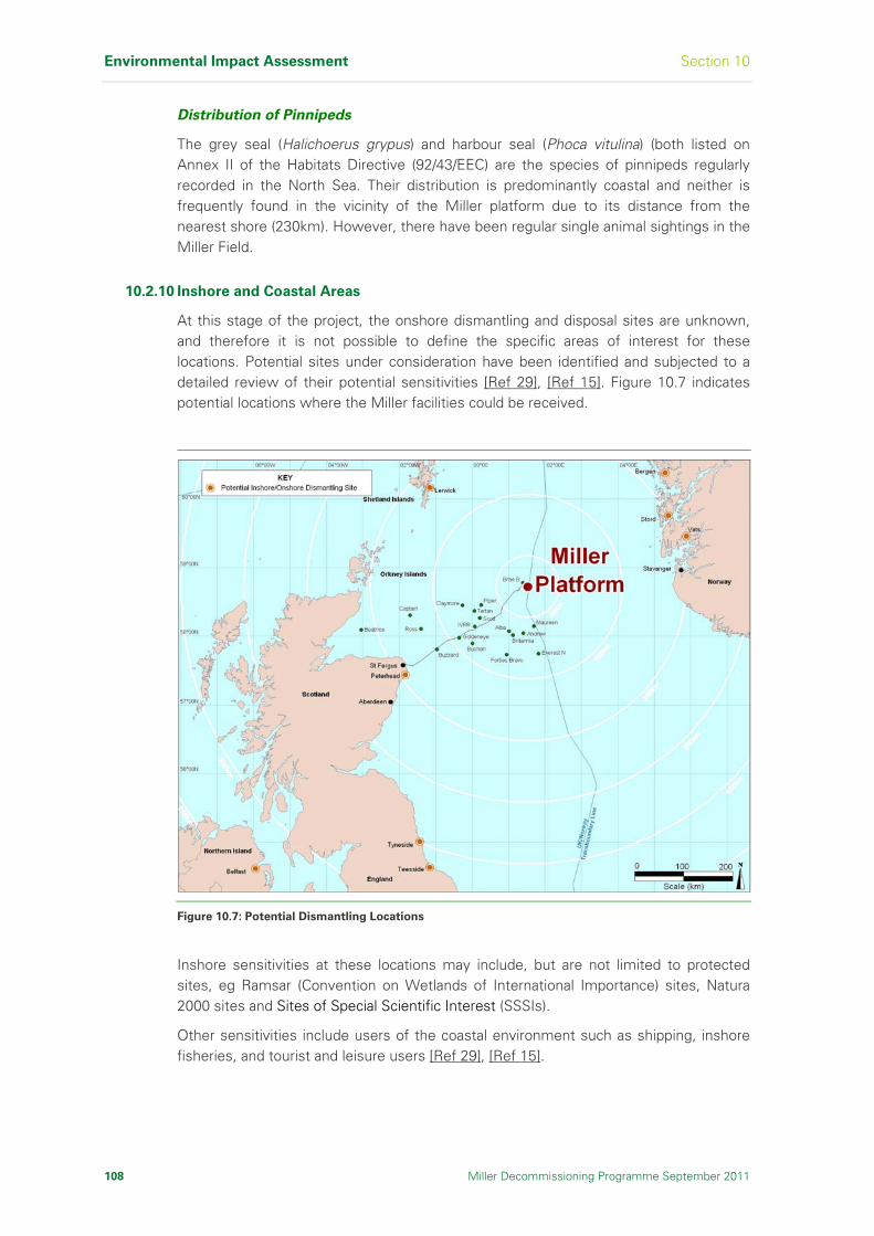
Environmental Impact Assessment Section 10
108 Miller Decommissioning Programme September 2011
Distribution of Pinnipeds
The grey seal (Halichoerus grypus) and harbour seal (Phoca vitulina) (both listed on Annex II of the Habitats Directive (92/43/EEC) are the species of pinnipeds regularly recorded in the North Sea. Their distribution is predominantly coastal and neither is frequently found in the vicinity of the Miller platform due to its distance from the nearest shore (230km). However, there have been regular single animal sightings in the Miller Field.
10.2.10 Inshore and Coastal Areas
At this stage of the project, the onshore dismantling and disposal sites are unknown, and therefore it is not possible to define the specific areas of interest for these locations. Potential sites under consideration have been identified and subjected to a detailed review of their potential sensitivities [Ref 29], [Ref 15]. Figure 10.7 indicates potential locations where the Miller facilities could be received.
Figure 10.7: Potential Dismantling Locations
Inshore sensitivities at these locations may include, but are not limited to protected sites, eg Ramsar (Convention on Wetlands of International Importance) sites, Natura 2000 sites and Sites of Special Scientific Interest (SSSIs).
Other sensitivities include users of the coastal environment such as shipping, inshore fisheries, and tourist and leisure users [Ref 29], [Ref 15].

Section 10 Environmental Impact Assessment
Miller Decommissioning Programme September 2011 109
If part of the decommissioning process is undertaken in inshore and coastal waters, close to protected sites, then under The Conservation (Natural Habitats &c) Regulations 1994, an appropriate assessment would be required to be undertaken where activities are likely to have a significant effect. Where decommissioning activities are carried out within a classified Special Protection Area (SPA) or Special Area of Conservation (SAC), then appropriate assessment is mandatory.
10.3 Conservation Interest
The EC Habitats Directive (92/43/EEC) and the EC Wild Birds Directive (79/409/EEC), are the main instruments of the European Union for safeguarding biodiversity.
The Offshore Petroleum Activities (Conservation of Habitats) Regulations (SI 2001 No 1754) have been introduced and implement the EC Habitats Directive in UK law. These regulations apply to UK waters beyond 22km (12nm) and up to 370km (200nm) offshore.
10.3.1 Offshore Conservation
The closest offshore candidate site for conservation to Miller is the Braemar pockmark. Pockmarks which contain carbonate structures are of particular conservation interest due to the potential for unique biological assemblages to develop. The Braemar pockmark has been nominated as a candidate Special Area of Conservation (cSAC) and is located over 27.5km north of Miller.
Biogenic reefs, such as those formed by Sabellaria spinulosa or Lophelia pertusa, are also very unlikely to occur in the vicinity of Miller as the conditions are not favourable for the development of such reefs (which tend to be associated with a range of seabeds, including, hard substrata, shells and sandy gravel) [Ref 63]. Following an integrity management survey of the Miller jacket in 2008 [Ref 64], there was no evidence of naturally occurring reefs of Lophelia pertusa on the seabed within the area of the Miller Field or on the Miller structure itself.
10.3.2 Important Species
A number of marine species in UK waters have been identified for protection under Annex II of the EC Habitats Directive (92/43/EEC).
10.3.3 Cetaceans
The harbour porpoise and bottle-nosed dolphin are both listed in Annex II of the EC Habitats Directive (92/43/EEC). All cetaceans are listed in Annex II of CITES, Appendix II of the Bern Convention Annex, and in Appendix IV of the EC Habitats Directive as species of European Community interest and in need of strict protection. They are also protected under Schedule 5 of the Wildlife and Countryside Act 1981.
10.3.4 Fish
Of the 166 fish species recorded in Scottish marine waters, thirteen have been accorded protected status under UK or international legislation. Few of these have distributions that extend into the offshore waters of the North Sea.

Environmental Impact Assessment Section 10
110 Miller Decommissioning Programme September 2011
Examples that may occur seasonally in small numbers throughout the North Sea during zooplankton abundance include the basking shark (Cetorhinus maximus), tope (Galeorhinus galeus) and porbeagle (Lamna nasus). The common skate (Raja batis) can be found at low density throughout the northern part of the North Sea and the Angel Shark (Squatina californica) is rarely seen.
10.3.5 Birds
A large number of birds have been identified as candidates for Annex I protected species, some of which occur in the vicinity of Miller (northern fulmar, kittiwake, storm petrel, guillemot and herring gull). The identification of appropriate SPAs for these species is complicated by the tendency of birds to move from area to area, however no species occurs in sufficient numbers in the vicinity of Miller for the area to be considered as a candidate SPA.
10.4 Environmental Impact Assessment Methodology
10.4.1 General
A five stage Environmental Risk Assessment (ERA) was used to determine environmental risks and compare the different options that have been proposed for decommissioning of the Miller facilities.
The comparative Environmental Impact Assessment (EIA) [Ref 29] used an ERA approach widely used in the oil and other industries and is developed from the approach to risk assessment described in the British Standard BS 8800 [Ref 65], [Ref 66] and by the Department of Trade and Industry Guidelines for Environmental Statements [Ref 67] and updated 2008 draft DECC Guidance [Ref 68].
10.4.2 Activities and Impact Categories
The first stage was to identify all project activities that could affect the environment. This list of activities was derived from the project data available at the time, with further input provided by expert judgement and stakeholder opinions. Each activity was placed in broad impact categories presented in Table 10.2. Activities considered included both routine and accidental events. Consultation with stakeholders involved the Miller Section 29 Notice Holders contacting a wide range of organisations and providing information on and discussing the impacts of their activities, and identifying any issues of concern.
10.4.3 Environmental Issues Identification
The second stage was to hold an Environmental Issues Identification Workshop (ENVID) where a multi-disciplinary team of engineers and environmental professionals identified the potential environmental impacts from decommissioning activities, including lessons learned from previous decommissioning projects. The evaluation of the findings was based on the expert judgement of environmental professionals.
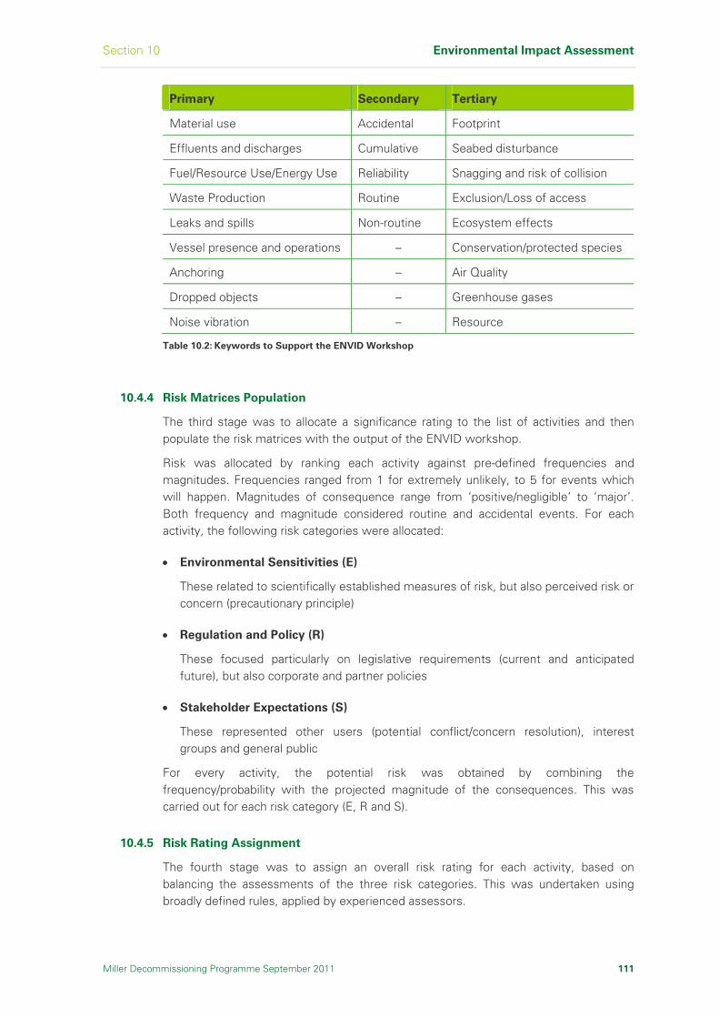
Section 10 Environmental Impact Assessment
Miller Decommissioning Programme September 2011 111
Primary Secondary Tertiary
Material use Accidental Footprint
Effluents and discharges Cumulative Seabed disturbance
Fuel/Resource Use/Energy Use Reliability Snagging and risk of collision
Waste Production Routine Exclusion/Loss of access
Leaks and spills Non-routine Ecosystem effects
Vessel presence and operations – Conservation/protected species
Anchoring – Air Quality
Dropped objects – Greenhouse gases
Noise vibration – Resource
Table 10.2: Keywords to Support the ENVID Workshop
10.4.4 Risk Matrices Population
The third stage was to allocate a significance rating to the list of activities and then populate the risk matrices with the output of the ENVID workshop.
Risk was allocated by ranking each activity against pre-defined frequencies and magnitudes. Frequencies ranged from 1 for extremely unlikely, to 5 for events which will happen. Magnitudes of consequence range from ‘positive/negligible’ to ‘major’. Both frequency and magnitude considered routine and accidental events. For each activity, the following risk categories were allocated:
Environmental Sensitivities (E)
These related to scientifically established measures of risk, but also perceived risk or concern (precautionary principle)
Regulation and Policy (R)
These focused particularly on legislative requirements (current and anticipated future), but also corporate and partner policies
Stakeholder Expectations (S)
These represented other users (potential conflict/concern resolution), interest groups and general public
For every activity, the potential risk was obtained by combining the frequency/probability with the projected magnitude of the consequences. This was carried out for each risk category (E, R and S).
10.4.5 Risk Rating Assignment
The fourth stage was to assign an overall risk rating for each activity, based on balancing the assessments of the three risk categories. This was undertaken using broadly defined rules, applied by experienced assessors.

Environmental Impact Assessment Section 10
112 Miller Decommissioning Programme September 2011
Key rules used were:
Major regulatory classification deemed the final rating ‘major’
An issue rated major by any risk category usually remained ‘major’
An issue rated moderate by two-three risk categories was seriously considered for ‘major’ rating in the final rating
All lower ratings were examined for important negative criteria before rating as ‘negligible’, and in cases of uncertainty an issue was rated as presenting minor risk.
The significance classification in Table 10.3 was then used to consistently assign an overall risk level to each activity.
Frequency/Probability
Rating Regulatory Env’ment Stakeholder 5 4 3 2 1
Major
Prohibited or major breach in consent
Major Impact
International or national concerns
Highly Significant
Highly Significant
Highly Significant
Highly Significant
Significant
Moderate
Potential non- compliance
Moderate Impact
Regional or community concerns
Highly Significant
Highly Significant Significant Significant
Not Significant
Minor
No specific consent limits
Minor Impact
Local or individual concerns
Significant Significant Not Significant
Not Significant
Insignificant
Negligible
Best practice guidance
Negligible Impact
Limited interest
Not Significant
Not Significant Insignificant Insignificant Insignificant
Positive/
No Impact
No regulation or guidance
Positive or No Impact
No public interest
No impact/ Positive
No Impact/ Positive
No Impact/ Positive
No Impact/ Positive
No Impact/ Positive
Highly Significant An unacceptable risk that must be eliminated or reduced to an acceptable level by developing risk-specific mitigation and/or controls.
Significant A risk that can be accepted but that should be further reduced by generic and risk-specific mitigation and/or controls.
Not Significant A risk that has an effect that is considered to be of little consequence. Can be further reduced by generic mitigation and controls.
Insignificant A risk that has an effect that is trivial. Often will not require mitigation or control.
No Impact/Positive A risk that has no effect or a positive effect.
Table 10.3: Environmental Significance and Definitions of Significance
10.4.6 Significant Potential Impacts Screening
The final stage in the ERA was to screen the activities. Impact categories with ‘highly significant’ and/or ‘significant’ activities, were carried forward for further consideration. Impact categories with activities allocated to ‘not significant’, ‘insignificant’ and ‘no impact/positive’ ratings were screened out and not considered further.
The following ‘significant’ and ‘highly significant’ risks were carried forward:
Offshore Impacts:
Emissions to air (vessels)
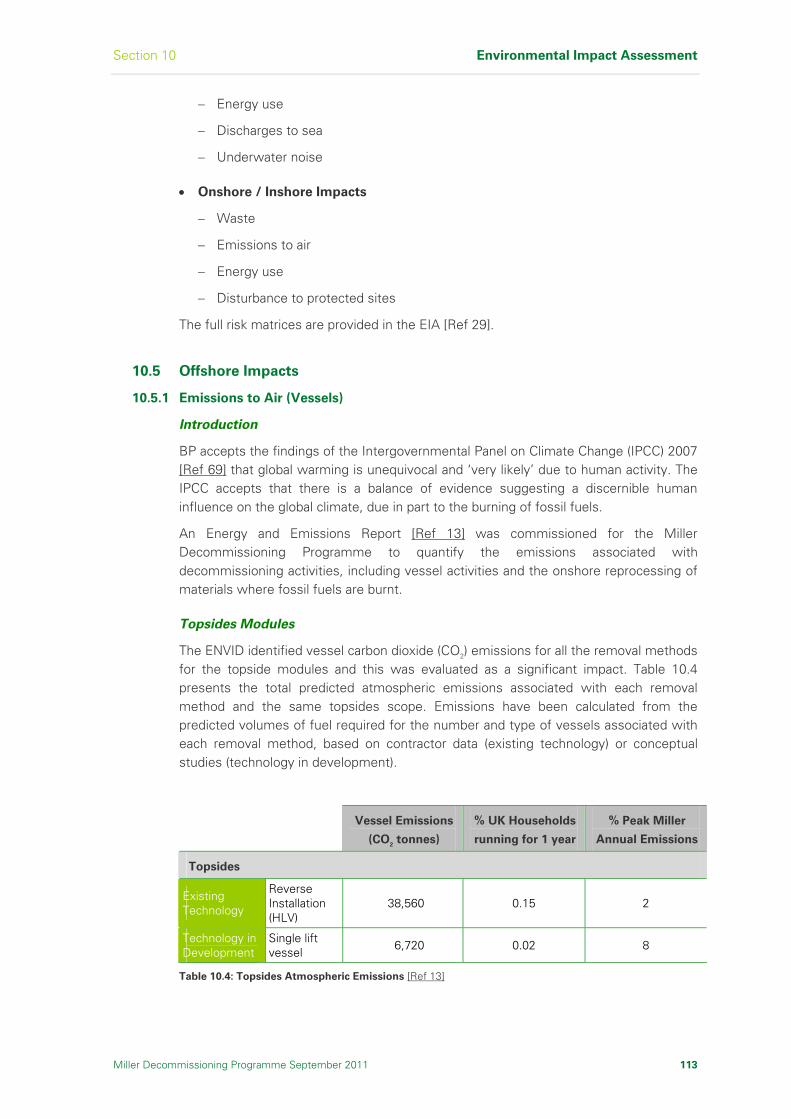
Section 10 Environmental Impact Assessment
Miller Decommissioning Programme September 2011 113
Energy use
Discharges to sea
Underwater noise
Onshore / Inshore Impacts
Waste
Emissions to air
Energy use
Disturbance to protected sites
The full risk matrices are provided in the EIA [Ref 29].
10.5 Offshore Impacts
10.5.1 Emissions to Air (Vessels)
Introduction
BP accepts the findings of the Intergovernmental Panel on Climate Change (IPCC) 2007 [Ref 69] that global warming is unequivocal and ‘very likely’ due to human activity. The IPCC accepts that there is a balance of evidence suggesting a discernible human influence on the global climate, due in part to the burning of fossil fuels.
An Energy and Emissions Report [Ref 13] was commissioned for the Miller Decommissioning Programme to quantify the emissions associated with decommissioning activities, including vessel activities and the onshore reprocessing of materials where fossil fuels are burnt.
Topsides Modules
The ENVID identified vessel carbon dioxide (CO2) emissions for all the removal methods for the topside modules and this was evaluated as a significant impact. Table 10.4 presents the total predicted atmospheric emissions associated with each removal method and the same topsides scope. Emissions have been calculated from the predicted volumes of fuel required for the number and type of vessels associated with each removal method, based on contractor data (existing technology) or conceptual studies (technology in development).
Vessel Emissions
(CO2 tonnes)
% UK Households
running for 1 year
% Peak Miller
Annual Emissions
Topsides
Existing Technology
Reverse Installation (HLV)
38,560 0.15 2
Technology in Development
Single lift vessel
6,720 0.02 8
Table 10.4: Topsides Atmospheric Emissions [Ref 13]

Environmental Impact Assessment Section 10
114 Miller Decommissioning Programme September 2011
To set these emissions into context, they have been compared as a percentage of the average annual CO2 emissions from UK Households and the annual CO2 emissions from the Miller platform during its peak production [Ref 13].
When the technologies are compared, there is a significant difference of 83% fewer CO2 emissions for technology in development. This suggests that if technology in development is brought to the market there is an opportunity to reduce these emissions in the future.
Jacket
Vessel emissions (CO2) for jacket removal were calculated using the same methodology as used to calculate topsides modules removal and is presented in Table 10.5.
Vessel Emissions
(CO2 tonnes)
% UK Households
running for 1 year
% Peak Miller
Annual Emissions
Jacket
Existing Technology
Offshore Deconstruction (full removal – HLV A
10,867 0.04 3
Offshore Deconstruction (full removal – HLV B
43,389 0.17 10
Offshore Deconstruction (partial removal – HLV A
7,379 0.03 2
Offshore Deconstruction (partial removal HLV B
30,982 0.12 7
Technology in Development
Float and Tow (full removal)
10,739 0. 04 3
Single lift – ship-shaped vessel (full removal)
11,936 0. 05 3
Single lift – concrete monohull (full removal)
12,474 0. 05 3
Table 10.5: Jacket Atmospheric Emissions [Ref 13]
Only the two existing technology methods can be compared for both full and partial jacket removal, as technology in development is based on single lift. When compared, it is demonstrated that there is a correlation between the proportion of jacket removed and CO2 emissions, as both the existing methods demonstrate reduced emissions for partial jacket removal.

Section 10 Environmental Impact Assessment
Miller Decommissioning Programme September 2011 115
The predicted emissions for technology in development methods for full jacket removal are in the region of 70% less CO2 compared with existing methods, but is based on conceptual studies and not from experienced contractor data. This also does not acknowledge a greater probability of technical failure for full removal, especially for technology in development methods which are conceptual and not based on engineering, which could lead to vessels in the Miller Field for longer with an increase in emissions.
Cuttings pile
Cuttings pile removal methods studied [Ref 22], [Ref 50], identified that vessels would be required for this activity. Vessels would also be involved in monitoring activities where the pile was left in situ. These vessel operations were identified in the ENVID as significant.
Total predicted emissions from vessels during any potential activity involving the cuttings pile are presented in Table 10.6. The least amount of vessel associated CO2 emissions are from leaving the cuttings in situ with periodic monitoring, with the highest emissions from full recovery of the pile.
Vessel Emissions
(CO2 tonnes)
% UK Households
running for 1 year
% Peak Miller
Annual Emissions
Cuttings Pile
Partial Disturbance 1,658 0.006 0.4
Partial Recovery with onshore disposal
2,938 0.01 0.7
Partial recovery with remote reinjection
4,794 0.02 1
Full recovery with onshore disposal
5,626 0.02 1
Full recovery with remote reinjection
9,146 0.04 2
Leave and monitor 256 0.001 0.06
Leave and cover 4,446 0.02 1
Table 10.6: Cuttings Pile Atmospheric Emissions [Ref 13]
Mitigation
All vessels employed during decommissioning operations will comply with MARPOL 73/78 Annex VI on air pollution. Any future contracting strategy would consider the most efficient schedule of activities to ensure durations were minimised.
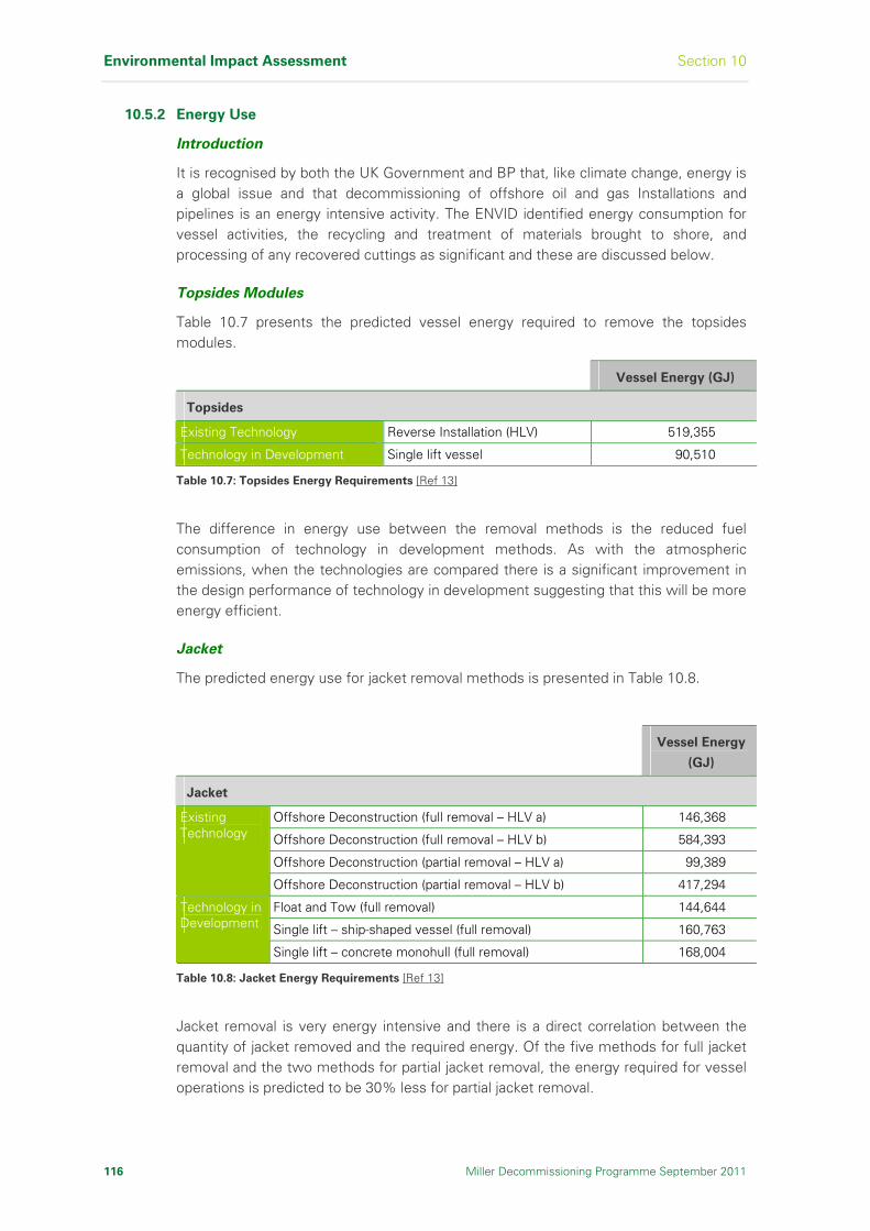
Environmental Impact Assessment Section 10
116 Miller Decommissioning Programme September 2011
10.5.2 Energy Use
Introduction
It is recognised by both the UK Government and BP that, like climate change, energy is a global issue and that decommissioning of offshore oil and gas Installations and pipelines is an energy intensive activity. The ENVID identified energy consumption for vessel activities, the recycling and treatment of materials brought to shore, and processing of any recovered cuttings as significant and these are discussed below.
Topsides Modules
Table 10.7 presents the predicted vessel energy required to remove the topsides modules.
Vessel Energy (GJ)
Topsides
Existing Technology Reverse Installation (HLV) 519,355
Technology in Development Single lift vessel 90,510
Table 10.7: Topsides Energy Requirements [Ref 13]
The difference in energy use between the removal methods is the reduced fuel consumption of technology in development methods. As with the atmospheric emissions, when the technologies are compared there is a significant improvement in the design performance of technology in development suggesting that this will be more energy efficient.
Jacket
The predicted energy use for jacket removal methods is presented in Table 10.8.
Vessel Energy
(GJ)
Jacket
Offshore Deconstruction (full removal – HLV a) 146,368
Offshore Deconstruction (full removal – HLV b) 584,393
Offshore Deconstruction (partial removal – HLV a) 99,389
Existing Technology
Offshore Deconstruction (partial removal – HLV b) 417,294
Float and Tow (full removal) 144,644
Single lift – ship-shaped vessel (full removal) 160,763
Technology in Development
Single lift – concrete monohull (full removal) 168,004
Table 10.8: Jacket Energy Requirements [Ref 13]
Jacket removal is very energy intensive and there is a direct correlation between the quantity of jacket removed and the required energy. Of the five methods for full jacket removal and the two methods for partial jacket removal, the energy required for vessel operations is predicted to be 30% less for partial jacket removal.

Section 10 Environmental Impact Assessment
Miller Decommissioning Programme September 2011 117
Only the two existing technology methods have been assessed for both full and partial jacket removal. The difference in energy use for the removal option shows 60% less energy being required for partial versus full jacket removal. This was attributed to one of the vessels using dynamic positioning and the other anchored, and both with different supporting vessel needs.
Although the energy use for full jacket removal is less for technology in development, there is a higher probability of technical failure for the full removal option as these conceptual methods are design based scenarios.
Cuttings pile
Table 10.9 presents the energy requirements for decommissioning the cuttings pile.
Where there is little or no disturbance to the cuttings pile, there are limited energy requirements as relatively little or no vessel time is required.
Vessel emissions are linked to the proportion of cuttings recovered, ie more recovery takes more time and leads to greater emissions.
The worst energy requirement option in terms of vessel requirements, is full recovery with remote reinjection.
Vessel Energy (GJ)
Cuttings Pile
Partial Disturbance 22,326
Partial Recovery with onshore disposal 39,566
Partial recovery with remote reinjection 65,564
Full recovery with onshore disposal 75,770
Full recovery with remote reinjection 123,180
Leave and monitor 3,448
Leave and cover 59,887
Table 10.9: Cuttings Pile Energy Requirements [Ref 13]
Mitigation
All vessels employed during decommissioning operations will comply with MARPOL 73/78 Annex VI on air pollution. Any future contracting strategy would consider the most efficient schedule of activities to ensure durations were minimised.
10.5.3 Discharges to Sea
Introduction
During the topsides modules and jacket removal phases of the Decommissioning Programme there will be no significant inventories of hydrocarbons or chemicals present within the structures, as the topsides will be gross hydrocarbons free, isolated from the reservoir, and the process plant will have been engineered down and flushed.

Environmental Impact Assessment Section 10
118 Miller Decommissioning Programme September 2011
The frequency of fuel bunkering will depend on the type and duration of vessels in the Miller Field for decommissioning activities, therefore the level of spill risk will be comparable to the normal operational risk associated with these vessels. The only remaining discharge to sea identified in the ENVID workshop as potentially significant, was re-suspension of the cuttings pile.
Jacket
Throughout the comparative assessment process, jacket removal has been assessed independently of the cuttings pile, but it was recognised during the ENVID (refer to Table 10.10) that for full jacket removal, access to the footings is required.
Re-suspended
cuttings
pile/hydrocarbons
Placement of
aggregate over
cuttings pile
Cuttings Pile
Partial Disturbance Full Jacket Removal Partial Recovery with
onshore disposal
Partial recovery with remote reinjection
Full recovery with remote reinjection
Full recovery with onshore disposal
Leave and monitor Partial Jacket Removal Leave and cover
Table 10.10: Discharges to Sea
The cuttings pile surrounds the lower levels of two of the jacket legs as well as a number of bracings. To safely remove the footings this part of the cuttings pile would have to be moved. In addition, there would be additional disturbance to the pile when the jacket is lifted from the seabed.
Partial dispersion and recovery of the cuttings would lead to contaminated cuttings material being re-suspended within the water column, with the potential impact on marine life in the vicinity of the cuttings pile disturbance. This impact would likely be proportionate to the amount of cuttings pile disturbance.
10.5.4 Underwater Noise
Introduction
There is concern about the effects of anthropogenic noise on cetaceans (whales, dolphins and porpoises). Cetaceans use sound to communicate with members of their own species, and for many toothed cetaceans, sound is also used to build up an image of their environment and to detect prey and predators. Potential effects of industrial noise on cetaceans include direct effects on hearing, displacement of the cetaceans themselves and stress and indirect effects such as displacement of prey species.

Section 10 Environmental Impact Assessment
Miller Decommissioning Programme September 2011 119
The ENVID identified that underwater noise from vessel presence and the contingency use of explosives was a significant issue. Therefore, to further understand this impact, a noise modelling study [Ref 39] was undertaken to assess the noise levels associated with the decommissioning activities.
Topsides Modules
The only differentiator for the impact of noise in topsides decommissioning is the number of vessels present and their duration in the Miller Field. The reverse installation methods have the highest number of vessels with the longest durations and therefore represent the worst-case in terms of noise.
Jacket
Vessel noise during decommissioning operations will be a major contributor to the overall noise in the offshore area around the Miller platform given the number of vessels present. The key factors in determining the total energy output is the time taken for each operation, the number of vessels present and their duration, as there is no difference in the noise levels associated with the different cutting techniques [Ref 39].
The design specifications for technology in development methods have the lowest overall noise energy output. The offshore deconstruction activity using existing technology has the greatest vessel requirements, for the greatest duration and a higher total noise energy output. However, noise associated with vessels and cutting operations are considerably below the levels at which lethal injury or physical disturbance to fish and marine mammals might occur [Ref 39].
It is assumed that cutting methods such as diamond wire, Abrasive Water Jet (AWJ) and mechanical cutting would be applied. The number of jacket cuts varies between removal options and the method of removal. Should these cutting methods prove ineffective, contingency use of explosives may be considered.
Depending on the size of members requiring cutting, then an explosive charge of between 2.7 - 200kg may be required. With charges of these sizes, lethal injury can be expected up to approximately 110m, with physical injuries expected up to 800m [Ref 39] away.
In addition to the noise associated with explosive activities, the blast will cause shock waves in the water [Ref 40] which will also have the potential to cause harm to marine life that may be present in the area. Based on work undertaken by Subacoustech on the use of explosives during decommissioning [Ref 39], for a typical 45kg charge the distance at which the shock wave was estimated to fall to a level where there would be low expectation of trivial blast injuries was approximately 2km [Ref 70]. At distances between 75 - 800m, the levels would be sufficient to cause moderately severe blast injuries [Ref 70].
Environmental Impact Assessment Section 10
120 Miller Decommissioning Programme September 2011
Cuttings Pile
As with the topsides, the key differentiator between noise impacts from each of the proposed options for decommissioning of the topsides is the number of vessels and their duration in the Miller Field. The options which have the lowest vessel requirements and therefore lowest noise impacts are partial disturbance and leave in situ. Full recovery of the cuttings pile, for either remote re-injection or onshore disposal, would have the highest level of vessel activity and highest noise impacts.
Mitigation
Should the contingent use of explosives be exercised, all activities will be carried out in line with UK legislation and following the guidelines for minimising acoustic disturbance to marine mammals from explosives.
As far as practicable and with due regard to logistical and safety requirements, the number of vessels in the area at any one time will be optimised.
10.6 Onshore/Inshore Impacts
The ENVID highlighted the geographical locations at which impacts may be expected to occur, ie offshore, inshore or onshore. It also identified that where removal scope was reduced offshore this was transferred to inshore or quayside/onshore locations.
10.6.1 Waste
Introduction
The ENVID identified residual waste from topsides modules dismantlement, including NORM in the form of a barium sulphate scale contaminated by radium 226 and radium 228 plus their progeny, and any onshore treatment of recovered cuttings pile material, has significant impacts requiring further consideration.
Topsides Modules
The topsides modules are gross hydrocarbons and chemical free. The process plant has been emptied of all inventories flushed with seawater, engineered down and left vented to atmosphere. Once equipment / material have been removed for re-use or recycling, the residual waste will be recovered for treatment and / or disposal. This material is likely to consist of hazardous / non-hazardous waste and NORM scale.
If these operations are undertaken at a UK onshore site, then that site will be subject to rigorous assessment and confirmation that all the necessary permits, procedures, competences and other requirements were in place.
If the topsides modules are sent overseas for dismantlement, then the current UK Management Plan for the Export and Import of Waste will allow this export of material for the purpose of recovery. Agreement will be reached with the UK and Overseas Regulators regarding the disposal of the NORM contaminated wastes arising from this process. This has significant implications on any future contracting strategy if these regulatory agreements cannot be reached prior to award of contract.

Section 10 Environmental Impact Assessment
Miller Decommissioning Programme September 2011 121
Within the topsides facilities, NORM deposits contaminated with radium-226 and 228 and progeny of varying levels of activity are distributed predominately within the produced water system. The separators and other vessels have historically been cleaned offshore under licence and, during the engineering down phase, these were cleaned of gross scale and sand. There are a number of options (both offshore and onshore) for the disposal of NORM deposits from the Miller platform but, prior to any disposal, the NORM scales and deposits have to be removed from the contaminated pipework, valves and equipment.
An evaluation of these options recognised that 100% removal of NORM deposits offshore will not be technically possible, due to inaccessibility of some equipment/pipework and removal methods currently available, therefore some onshore removal and disposal will be required for residual scale. All future handling, removal, treatment and disposal of NORM deposits shall be undertaken by competent authorised contractors at licensed sites with all the necessary permits, licences and consents.
Cuttings Pile
All potential waste issues relating to the cuttings pile are limited to recovery options. Partial or full recovery of the pile will require onshore treatment for some of the options identified in the ENVID. An OGUK Drill Cuttings Initiative [Ref 50] study reviewed treatment methods and is summarised below.
Treatment would commence with the bulk separation of the water and solids, eg this could be done using mud shakers and screens offshore or onshore. The water wet cuttings material would then require further water extraction with the water product treated further, eg at a production / ballast water treatment facilities.
The oily solids could be disposed to hazardous landfill or the hydrocarbons recovered by direct / indirect thermal desorption or solvent extraction. This would produce a solid and an oil waste.
The oil could then be reused as a fuel for the thermal treatment process, a base for fresh drilling muds or reconditioned as a fuel for power stations or quarry operations. The solid is likely to be classified as a special / hazardous waste however, in some instances depending on its composition, it could be re-used as a liner and / or cell wall building material in a landfill site otherwise it would be disposed to landfill.
Mitigation
For the onshore treatment and disposal of Miller material, the waste hierarchy will be applied and material will be reused and recycled wherever possible in preference to disposal. It is anticipated that up to 97% of the recovered material will be reused or recycled, and contractual arrangements and other incentives would be put in place to ensure that this figure is maximised.
All waste materials will be transferred, treated or disposed of by licensed contractors at licensed sites with all the necessary permits, licences and consents. Throughout these activities ‘Duty of Care’ will be exercised through an appropriate assurance process.
On completion, the quantities of material, reused, recycled and disposed, and the sites and methods used to dispose of hazardous waste will be compiled for reporting.

Environmental Impact Assessment Section 10
122 Miller Decommissioning Programme September 2011
10.6.2 Onshore Energy Use and Atmospheric Emissions
The ENVID identified energy required and the onshore emissions (CO2) for the reprocessing of materials as a significant impact and this is discussed in this section.
The energy and emissions data presented here were generated for the Energy and Emissions Report [Ref 13] which used established criteria to calculate emissions. The report also presented the onshore emissions as a percentage of the average annual CO2
emissions from UK Households and the annual CO2 emissions from the Miller platform during its peak production [Ref 13].
Topsides Modules
The quantity of material available for reprocessing from the topsides modules does not vary between the removal methods. Therefore, the predicted energy use and emissions listed in Table 10.11, would be expected for topsides module reprocessing where all the steel, aluminium and copper is recycled rather than re-used.
Emissions
(CO2 tonnes)
Energy (GJ) % UK Households
running for 1 year
% Peak Miller Annual
Emissions
25,279 264,371 0.1 6
Table 10.11: Predicted Energy and CO2 Emissions for Topsides Modules Reprocessing Onshore [Ref 13]
Jacket
As detailed in Table 10.12, the energy required for reprocessing the structural steel recovered from the full jacket is approximately 34% more than for partial jacket removal.
Emissions
(CO2
tonnes)
Energy
(GJ)
% UK Households
running for 1 year
% Peak Miller
Annual
Emissions
Jacket
Existing Technology
Full removal
16,200 148,690 0.06 4
Partial removal
10,188 94,471 0.04 2
Technology in Development
Full removal
16,200 148,690 0.06 4
Table 10.12: Predicted Energy and CO2 Emissions for Jacket Reprocessing Onshore [Ref 13]
Cuttings Pile
The onshore treatment options for any recovered cuttings pile is described in the Section 10.6.1. This is a very energy intensive process and Table 10.13 provides the associated predicted CO2 emissions.

Section 10 Environmental Impact Assessment
Miller Decommissioning Programme September 2011 123
Emissions
(CO2
tonnes)
Energy
(GJ)
% UK Households
running for 1 year
% Peak Miller
Annual
Emissions
Cuttings Pile
Partial disturbance / no recovery
- - - -
Partial recovery with onshore disposal
- 39,566 - -
Partial recovery with remote reinjection
- - -
Full recovery with onshore disposal
- 63,891 - -
Full recovery with remote reinjection
- - -
Leave and monitor / no recovery
- - -
Leave and cover (aggregates)
56,011 1,482,651 0.2 13
Table 10.13: Predicted Energy and CO2 Emissions for Cuttings Pile Reprocessing Onshore [Ref 13]
Mitigation
During the Decommissioning Programme, emphasis will be placed on the reuse of recovered equipment. Where this is not possible material will be recycled.
10.6.3 Disturbance of Protected Sites
The ENVID study identified that where removal scope was reduced offshore this was transferred to inshore or quayside/onshore locations. The consequence of disturbance in inshore waters was regarded as being more significant where there may be potential to have adverse effects on any special areas of conservation or other protected sites.
Jacket
The potential inshore impacts were only identified for full jacket removal options using technology which is in development and based on the current design specifications.
The impacts identified were mostly associated with anchor handling or physical contact of the towed jacket with the seabed. One proposed method involves upending the jacket onto a cargo barge and towing to a quayside location. Another removal method involves placing the jacket onto the inshore seabed, dismantling piece-small and gradually moving the jacket into shallower water as it reduces in size.
Mitigation
Where an inshore location may be subject to seabed disturbance, then an appropriate assessment, as required by the relevant regulatory authority, will be carried out.
Environmental Impact Assessment Section 10
124 Miller Decommissioning Programme September 2011
10.6.4 Interaction with Other Sea Users (Fishing Gear Impact)
The ENVID identified that a potential snagging risk will remain if the platform jacket footings are left in place. The 500m exclusion zone around the Miller jacket footings will no longer apply, however the presence of the remains of the jacket will be published through FishSafe, KIS-UKCS, Kingfisher bulletins and Admiralty charts will be updated to reflect the potential obstruction.
10.7 Summary
All recovery and disposal options for both the topsides modules and the jacket were found to be energy intensive, with the associated atmospheric emissions contributing to climate change.
The offshore removal operations posed the most significant impact in terms of energy use with a direct correlation between quantities removed - marine vessel operations used approximately 30% less energy for partial removal and 34% more for reprocessing the structural steel recovered from the full jacket. However, technical failure of the more challenging full removal option for both existing and conceptual methods, would result in a schedule overrun with vessels being present for longer and this would increase energy use, atmospheric emissions and more noise disturbance.
When technology in development is compared with existing technology for removal, the design specifications suggest that there may be an improvement in the performance of conceptual technologies which, if proven, could lead to more energy efficient operations. However, none of these technologies are presently suitable for the decommissioning of the Miller facilities.
Throughout the comparative assessment process, jacket removal has been assessed independently of the cuttings pile but it is recognised that for full removal of the jacket, access is required for cutting the jacket and drilling template piles. The cuttings pile has covered much of two of the jacket legs and this would have to be moved. Removal methods would give rise to suspension of cuttings material resulting in a potentially detrimental localised effect.
There would also be additional disturbance to the cuttings pile when the jacket is lifted from the seabed. Any onshore treatment of recovered cuttings pile material would also be very energy intensive. However, there will be no associated disturbance to the cuttings pile with partial removal to land, as the cut points on the jacket legs are located above the cuttings pile.
The EIA [Ref 29] conclusion is that energy and emissions can be minimised by partial jacket removal. The most effective outcome for the cuttings pile is to leave this undisturbed to degrade naturally therefore minimising seabed disturbance, energy use and atmospheric emissions. Where technology in development methods for jacket removal are developed and available, then inshore sites should be appropriately assessed.
Section 11 Interested Party Consultation
Miller Decommissioning Programme September 2011 125
11 Interested Party Consultation
This section describes how the Miller Section 29 Notice Holders have been
carrying out consultation with interested parties on issues arising from the
decision to decommission the Miller platform. It summarises the extent of
stakeholder engagement so far, including statutory public consultation and
how this will continue through the next phase of the Miller
Decommissioning Project.
11.1 Introduction
The Miller Section 29 Notice Holders are committed to engaging with stakeholders, providing information on and discussing the economic, environmental and social impact of our activities.
In the UK, the decommissioning process requires a statutory thirty-day public consultation plus consultation with four specifically nominated organisations as detailed in the DECC Guidance Notes [Ref 3]. This public consultation phase was undertaken between 24th May and 25th June 2010 in parallel with a review by the UK Government of the Miller Decommissioning Programme and the results are documented in Section 11.3. A copy of the Decommissioning Programme is available on the public website at www.bp.com/miller.
Before the public consultation stage, the Miller Section 29 Notice Holders contacted a wide range of organisations and individuals, including the statutory consultees identified in the DECC Guidance Notes [Ref 3], to invite expressions of interest in the Miller Decommissioning Programme.
11.2 Consultation Process
In October 2007, the Miller Section 29 Notice Holders sent invitations to a range of organisations and individuals, inviting them to register an interest in the Miller Decommissioning Programme. The invitation list was developed from existing stakeholder contacts, including those consulted during the North West Hutton Decommissioning Programme [Ref 47]. The Miller Section 29 Notice Holders asked each recipient to extend the invitation to anyone else within their organisation that they considered appropriate. A stakeholder register was established, based on responses received.
One of the organisations which responded, the Scottish Fishermen’s Federation (SFF), also requested a meeting to discuss the project in more detail and several meetings have been held with this organisation. To date, no other organisations have requested further information or a meeting, beyond the information which has already been made available.
A public website www.bp.com/miller was set up to provide information on the Miller Decommissioning Programme and this will continue to be updated throughout the life of the Decommissioning Programme. The option of communicating by email directly with company representatives through the website has also been available since the website was established.

Interested Party Consultation Section 11
126 Miller Decommissioning Programme September 2011
Each registered stakeholder is provided with email communications from the Miller Section 29 Notice Holders, giving updates on the status of the project and a reminder of the website address when more detailed information is posted.
11.3 Statutory Public Consultation
A 30 day statutory public consultation was held from 24th May to 25th June 2010, inviting comments from interested parties on the detailed proposals for Miller in a draft Decommissioning Programme dated May 2010.
To initiate this consultation, the following actions were taken:
Public notices were placed in the Times, Press and Journal and Edinburgh Gazette
A letter inviting comments was sent to the four organisations listed as statutory consultees – the Scottish Fishermen’s Federation (SFF), the National Federation of Fishermen’s Organisations, the Northern Ireland Fishermen’s Federation and Global Marine Systems Ltd
All registered stakeholders were advised of the start of public consultation and that the decommissioning programme could be viewed or downloaded from the public website at www.bp.com/miller or a hard copy requested from BP
Table 11.1 summarises the comments received from the public consultation. No comments were received as a result of the 30 day statutory public consultation from the general public.
Organisation Summary of Comments
Scottish Fishermen’s Federation (SFF)
Preference for full removal of all offshore hardware and note that the jacket footings will remain on the seabed
Welcome proposals for wells, topsides, pipeline “jewellery, debris removal and ongoing monitoring
Drill cuttings proposal noted and request that BP continues to engage with Stakeholders and contribute to ongoing debate
Welcome BP commitment to supporting the objectives of the Fisheries Legacy Trust Company (FLTC)
Northern Ireland Fishermen’s Federation
No comment
Global Marine Systems Ltd Recommend notifying owners of submarine
cables in the vicinity as a courtesy
Table 11.1: Summary of Comments from Statutory Consultees
Copies of the responses from the Statutory Consultees and the BP reply to the SFF are included in Appendices 11-A to 11-C.
Section 11 Interested Party Consultation
Miller Decommissioning Programme September 2011 127
11.4 OSPAR Consultation
OSPAR Decision 98/3 [Ref. 4] requires that all redundant Installations be completely removed to be reused, recycled or disposed of on land. However, OSPAR Decision 98/3 also allows a potential ‘derogation’ which is an exemption from the general presumption of total removal, for all or part of the footings of steel jacket installations weighing more than 10,000 tonnes and placed in the maritime area before 9th February 1999. Annex 2 to OSPAR Decision 98/3 details the process to be followed before such derogation can be considered and granted. This includes details of the assessment and consultation procedures to be followed.
The UK Government having accepted the case presented in this Decommissioning Programme for leaving the footings in place, then the Miller Section 29 Notice Holders produced an Assessment Document for the footings. The Document was based on a comparative assessment process which looked at the safety, environmental, technical, social and economic aspects of different solutions for the footings, and provided reasons supporting the case for the Miller footings to be left in place. The Assessment Document [Ref. 72] (www.bp.com/miller) was submitted to the UK Government for use in consulting with OSPAR Contracting Parties.
The UK Department of Energy and Climate Change (DECC) informed the OSPAR Executive Secretary in December 2010 that they were considering issuing a permit, under Paragraph 3a of OSPAR Decision 98/3, allowing for the disposal of the footings of the Miller steel jacket at their current location in the Miller field.
The OSPAR Executive Secretary sent the Assessment Document together with a letter from the UK Department of Energy and Climate Change to all the OSPAR Contracting Parties on 6th December 2010. By the end of the 16-week consultation period, allowed under 98/3, no objections had been received by the UK Department of Energy and Climate Change to the issuing of a permit.
Some of the Contracting Parties raised a number of issues for consideration. The issues and mitigations are summarised in Table 11.2 and copies of the Contracting Party letters are included in Appendix 11-D. The UK Government have responded to the issues raised by the Contracting Parties and where appropriate the issues will be the subject of conditions in the permit to be issued by the UK Authorities.

Interested Party Consultation Section 11
128 Miller Decommissioning Programme September 2011
Contracting Party Summary of Issues Summary of Mitigations
Denmark Potential risk to
fishermen and need for monitoring
Mitigation measures will be put in place and future monitoring system will be
agreed with DECC
Participation in the UK Fisheries Offshore Oil & Gas Legacy Trust Fund
Germany
Footings are a snagging hazard,
and potential risk to fishermen
Mitigation measures will be put in place including update of Fishsafe System
Netherlands Monitoring of the abandoned wells
Monitoring system will be agreed with DECC once post-decommissioning
survey results are known
Norway
Footings must be below the highest point of the piles
and markers should be installed
Footings will satisfy OSPAR decision 98/3 and mitigation measures for
identification of the footings will be put in place
Table 11.2: Summary of Comments from Contracting Parties
11.5 Letters from Section 29 Notice Holders
The OSPAR consultation, Section 11.4, completes the consultation process. The Miller Decommissioning Programme is now complete and can be formally submitted upon the request of the UK Department of Energy and Climate Change (DECC). This completion includes letters of support from the Miller Section 29 Notice Holders for the proposals detailed in the Programme, and these letters are included in Appendix 11-E.
Appendix 11-A Scottish Fishermen’s Federation Response and BP Reply
Miller Decommissioning Programme September 2011 129

Scottish Fishermen’s Federation Response and BP Reply Appendix 11-A
130 Miller Decommissioning Programme September 2011
Appendix 11-A Scottish Fishermen’s Federation Response and BP Reply
Miller Decommissioning Programme September 2011 131
Scottish Fishermen’s Federation Response and BP Reply Appendix 11-A
132 Miller Decommissioning Programme September 2011
Appendix 11-B Northern Ireland Fishermen’s Federation Response
Miller Decommissioning Programme September 2011 133

Northern Ireland Fishermen’s Federation Response Appendix 11-B
134 Miller Decommissioning Programme September 2011
I n t e n t i o n a l l y L e f t B l a n k
Appendix 11-C Global Marine Systems Limited Response
Miller Decommissioning Programme September 2011 135
Global Marine Systems Limited Response Appendix 11-C
136 Miller Decommissioning Programme September 2011
I n t e n t i o n a l l y L e f t B l a n k

Appendix 11-D Contracting Party Letters
Miller Decommissioning Programme September 2011 137
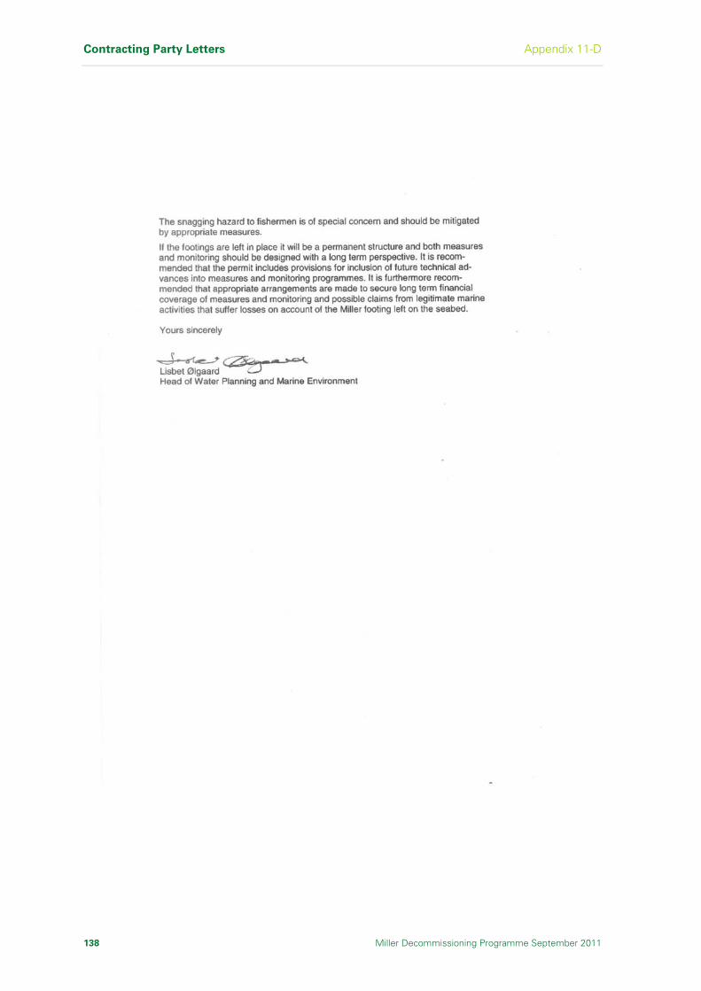
Contracting Party Letters Appendix 11-D
138 Miller Decommissioning Programme September 2011
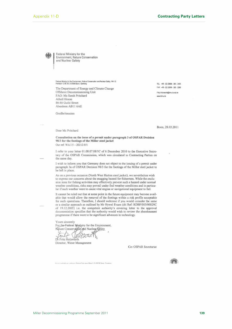
Appendix 11-D Contracting Party Letters
Miller Decommissioning Programme September 2011 139

Contracting Party Letters Appendix 11-D
140 Miller Decommissioning Programme September 2011
I n t e n t i o n a l l y L e f t B l a n k
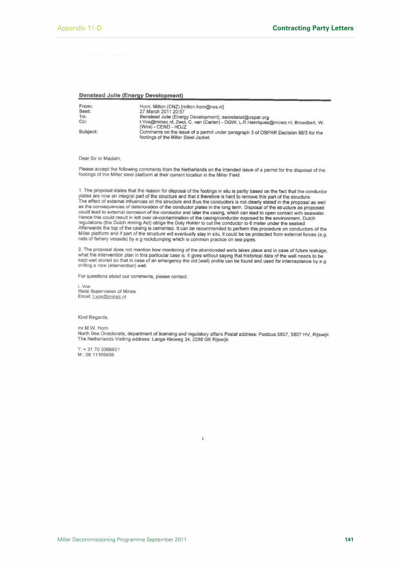
Appendix 11-D Contracting Party Letters
Miller Decommissioning Programme September 2011 141

Contracting Party Letters Appendix 11-D
142 Miller Decommissioning Programme September 2011
I n t e n t i o n a l l y L e f t B l a n k
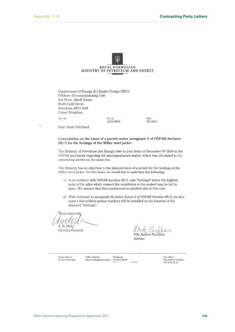
Appendix 11-D Contracting Party Letters
Miller Decommissioning Programme September 2011 143

Contracting Party Letters Appendix 11-D
144 Miller Decommissioning Programme September 2011
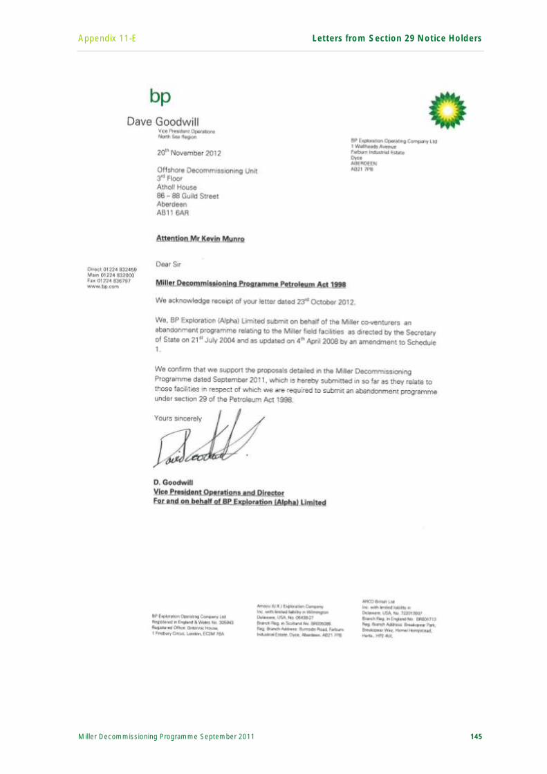
Appendix 11-E Letters from Section 29 Notice Holders
Miller Decommissioning Programme September 2011 145
H o l d i n g P a g e f o r S e c t i o n 2 9 N o t i c e H o l d e r L e t t e r 1

Letters from Section 29 Notice Holders Appendix 11-E
146 Miller Decommissioning Programme September 2011
I n t e n t i o n a l l y L e f t B l a n k
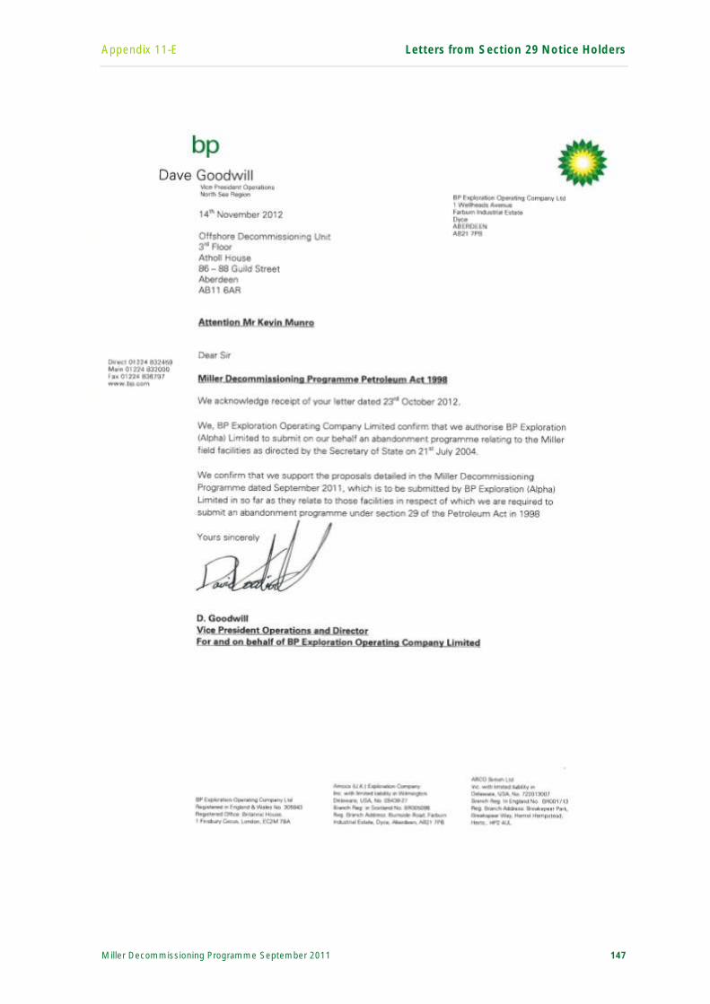
Appendix 11-E Letters from Section 29 Notice Holders
Miller Decommissioning Programme September 2011 147
H o l d i n g P a g e f o r S e c t i o n 2 9 N o t i c e H o l d e r L e t t e r 2

Letters from Section 29 Notice Holders Appendix 11-E
148 Miller Decommissioning Programme September 2011
I n t e n t i o n a l l y L e f t B l a n k
Appendix 11-E Letters from Section 29 Notice Holders
Miller Decommissioning Programme September 2011 149
H o l d i n g P a g e f o r S e c t i o n 2 9 N o t i c e H o l d e r L e t t e r 3

Letters from Section 29 Notice Holders Appendix 11-E
150 Miller Decommissioning Programme September 2011
I n t e n t i o n a l l y L e f t B l a n k

Appendix 11-E Letters from Section 29 Notice Holders
Miller Decommissioning Programme September 2011 151
H o l d i n g P a g e f o r S e c t i o n 2 9 N o t i c e H o l d e r L e t t e r 4

Letters from Section 29 Notice Holders Appendix 11-E
152 Miller Decommissioning Programme September 2011
I n t e n t i o n a l l y L e f t B l a n k

Section 12 Costs
Miller Decommissioning Programme September 2011 153
12 Costs
This section details the costs associated with the Miller Decommissioning
Programme, and the workscope covered by these costs.
The overall cost for the proposed Miller Decommissioning Programme as presented is expected to be in the order of £300 million when executed as a stand alone project.
The scope of work covered by this overall estimate includes:
The reservoir isolation work, which involved the abandonment of 22 wells and the removal of 22 well conductors
Topsides cleaning and engineering down activities
Platform logistics, operational and technical integrity support throughout the decommissioning activities
Pipelines hydrocarbons freeing and preservation
Modifications to the platform to remain in situ for the removal schedule window
Topsides removal and transportation to shore
Jacket removal and transportation to shore
Onshore receipt, reuse, recycle and disposal of all material
Post decommissioning subsea surveys, site clearance and future monitoring
Project management, engineering and procurement
Cost estimates have been developed for all aspects of the decommissioning activity assuming a stand alone project. The estimates are based on data from contractors, detailed studies and standard industry data. There are a range of uncertainties caused by a number of factors including technical, safety and environmental risks detailed in this Decommissioning Programme and also contracting risks associated with the work yet to be completed. Synergies with other similar activity projects will be investigated, and the majority of the work associated with the removal and the disposal of Miller will be competitively tendered. The tendering activity will mitigate the commercial uncertainty currently in the estimates.
Details of the cost estimate are commercially sensitive and have not been included in this Decommissioning Programme. However, a cost estimate has been provided to DECC as part of the approval process for the Decommissioning Programme.

Costs Section 12
154 Miller Decommissioning Programme September 2011
I n t e n t i o n a l l y L e f t B l a n k
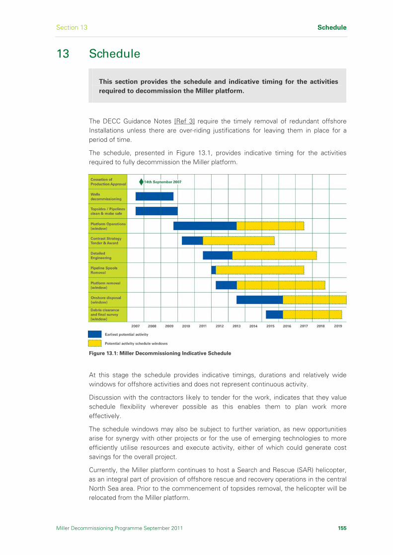
Section 13 Schedule
13 Schedule
This section provides the schedule and indicative timing for the activities
required to decommission the Miller platform.
The DECC Guidance Notes [Ref 3] require the timely removal of redundant offshore Installations unless there are over-riding justifications for leaving them in place for a period of time.
The schedule, presented in Figure 13.1, provides indicative timing for the activities required to fully decommission the Miller platform.
Figure 13.1: Miller Decommissioning Indicative Schedule
At this stage the schedule provides indicative timings, durations and relatively wide windows for offshore activities and does not represent continuous activity.
Discussion with the contractors likely to tender for the work, indicates that they value schedule flexibility wherever possible as this enables them to plan work more effectively.
The schedule windows may also be subject to further variation, as new opportunities arise for synergy with other projects or for the use of emerging technologies to more efficiently utilise resources and execute activity, either of which could generate cost savings for the overall project.
Currently, the Miller platform continues to host a Search and Rescue (SAR) helicopter, as an integral part of provision of offshore rescue and recovery operations in the central North Sea area. Prior to the commencement of topsides removal, the helicopter will be relocated from the Miller platform.
Miller Decommissioning Programme September 2011 155

Schedule Section 13
156 Miller Decommissioning Programme September 2011
I n t e n t i o n a l l y L e f t B l a n k

Section 14 Project Management and Verification
Miller Decommissioning Programme September 2011 157
14 Project Management and Verification
This section outlines BP’s project management and verification, and how
this applies to the Miller Decommissioning Programme.
14.1 Introduction
The Miller Decommissioning Project represents an important activity for the Section 29 Notice Holders. The project management process will require the rigorous levels of quality control, inspection and assurance that would be expected for a capital investment project of this size. BP as the Operator of the Field will be responsible for the implementation of the overall project management.
BP has a well developed, company-wide approach to project management and this is being applied to all aspects of the Miller Decommissioning project. A Project Management Team has been established to develop and implement the project from inception through to the completion of all operations and final inspections of the site.
BP group-wide functions provide the control for ensuring successful implementation of the project.
14.2 Operating Management System
BP recognises that Health, Safety, Security and Environmental (HSSE) performance is critical to the success of the business, and is distinctive world-wide in its pursuit of health, safety and environmental performance. BP’s commitment to HSE Performance is enshrined within its Operating Management System (OMS) [Ref 12].
The OMS [Ref 12] is fundamental to delivering safe and reliable operating activities in BP. It is the foundation for a responsible and high performing BP where our goals are simply stated: no accidents, no harm to people and no damage to the environment.
The OMS [Ref 12] provides a set of requirements and a systematic application of a performance improvement cycle to continuously improve the way BP operate. It also sets the boundaries and standards that will enable leaders to exercise control in a way that is clear and unambiguous.
The OMS [Ref 12] ‘Elements of Operating’ describe eight dimensions of how people, processes, plant and performance operate within BP. The elements are leadership, organization, risk, procedures, assets, optimization, privilege to operate and results.
The OMS eight ‘Elements of Operating’ and their associated principles are summarised below:
Element 1 Leadership - Our operating leaders are competent, exhibit visible, purposeful and systematic leadership and are respected by the organisations they lead
Element 2 Organisation - We have fit for purpose and agile organisations staffed with competent people and teams

Project Management and Verification Section 14
158 Miller Decommissioning Programme September 2011
Element 3 Risk - The workforce at all levels of our organisation understands and manages operating risk to prevent accidents and harm to people, to reduce damage to the environment and to achieve competitive performance
Element 4 Procedures - We document and rigorously follow procedures for safe, responsible and reliable operating
Element 5 Assets - Our plants, facilities, assets and floating systems are fit for purpose throughout the lifecycle of the operation
Element 6 Optimisation - Our operations are continuously optimised to improve performance and delivery from our assets
Element 7 Privilege to Operate - We deliver what is promised and address issues raised by our key stakeholders
Element 8 Results - Measurement is used to understand and sustain performance
As the project is defined further and moves towards the execution phase, all elements will be required to be assessed to ensure compliance and undertaking of the project with minimal risk.
14.3 Technical
The Miller Decommissioning Project will be executed within the framework of the BP Project Management Capital Value Process (CVP) and the BP OMS [Ref 12] discussed in Section 14.2. This sets the principles and controls for project delivery.
Technical delivery is core to the delivery of any project. This is managed within the CVP framework with engineering definition and construction developing in increasing detail as the project progresses through the CVP gated phases of Appraise – Select – Define - Execute – Operate, as applicable to a decommissioning project.
Key control for the technical execution of the project will be established through the Project Execution Plan (PEP), Statement of Requirement (SoR) and the Assurance Plans. The PEP sets out how the project will be executed and establishes key controls and communications. Contracting Strategy and clarity on interfaces and responsibilities is central to this execution.
The SoR is the prime technical document that sets out the technical requirements of the project and these include:
Technical objectives and philosophy
Site factors and data
Regulatory requirements
Design standards, with clarity on order of precedence
Engineering deliverables to execute and control the project
Third Party Compliance, permits and consents
The SoR develops into the basis of design and ultimately into the contractors’ detailed design briefs, documentation and procedures. A change-control process will be established by the project to ensure that the contractors deliver the technical objectives set out in the SoR.
Section 14 Project Management and Verification
Miller Decommissioning Programme September 2011 159
Decommissioning on the scale of Miller brings project challenges. It is a large brown-field project (ie it involves work with existing equipment) with all the attendant difficulties and uncertainties. Assurance Plans will be essential to review and challenge the engineering and execution of the project at all phases of the CVP. This will be done through audits and processes which will review critical areas of the project to ensure best practice is being achieved.
14.4 Reporting
BP will provide a quarterly written report on the progress of the decommissioning works to DECC. This report will include information on the following topics:
HSSE performance
Current project status
Changes to the Decommissioning Programme
Stakeholder engagement
Forthcoming key activities
Issues and concerns
The above report shall be in addition to the statutory and regulatory permits, consents and notifications that may be required during the execution of the project.
On completion of the project, no later than four months after completion of the offshore removal activity, including post-decommissioning surveys and debris clearance where applicable, a Close-Out Report will be submitted to DECC addressing major variations from the Decommissioning Programme, should there be any, and summarise the following:
Information on the outcome of the Decommissioning Programme as a whole, outlining how the major milestones were achieved, including confirmation that the work has been carried out in accordance with the terms of the Decommissioning Programme
An explanation of any variances from the Decommissioning Programme inclusive of why they occurred and any permits required as a result
The results of debris clearance and monitoring undertaken, inclusive of any independent verification activities and certifications
Results of post-decommissioning environmental sampling survey, including any immediate consequences of the decommissioning activity which have been observed. If necessary update the schedule for future environmental monitoring or monitoring of items left in place with reasons for the changes
Measures taken to manage the potential risks arising from any legacies, including participation in the UK Fisheries Offshore Oil & Gas Legacy Trust Fund Limited (FLTC), confirmation of marking any remains on mariners charts, inclusion in the Fishsafe System and installation of navigational aids
Provide a high level summary of actual costs and a general explanation of variances against forecast costs

Project Management and Verification Section 14
160 Miller Decommissioning Programme September 2011
Following submission of the Close-Out Report to DECC, the Operator shall place a copy of the report on their public website.
14.5 Verification
14.5.1 General
Specialist consultants will be engaged as required to ensure that satisfactory engineering and construction techniques are employed, and that work is performed to the satisfaction of the Section 29 Notice Holders and their insurers.
Well abandonment was subject to well examination under Regulation 18 of the Design and Construction Regulations (DCR) [Ref 71].
Verification activities will be undertaken to confirm that the Miller Decommissioning Programme has been delivered.
14.5.2 Miller Decommissioning Studies Independent Review Consultant
The Miller Section 29 Notice Holders appointed an Independent Review Consultant (IRC) to review the studies and reports associated with the development of the Miller Decommissioning Programme. The suitability of the terms of reference and the appointment of the consultant was confirmed with DECC.
The terms of reference for the independent review were as follows:
Read and review existing project documentation to ensure an understanding of the relevant issues for the comparative assessment process
Read and review the comparative assessment study work (including contractors scopes of work) commissioned for or produced by the Miller Section 29 Notice Holders
Provide view/guidance on the above in respect of the scope, clarity, completeness, methodology, relevance and objectivity of conclusions
Advise on any further research or actions to address identified gaps that would otherwise prevent an informed decision
Make recommendations for additional work as necessary which should be practicable and achievable within the timeframe for the Decommissioning Programme submission
The IRC concluded that sufficient information is in place for the Miller Section 29 Notice Holders to make an informed decision on the removal of the jacket footings. The full IRC report [Ref 8] is available on the Miller public website at: www.bp.com/miller.
14.6 Licences Associated with Decommissioning Miller
As the decommissioning project progresses, the Miller Section 29 Notice Holders will put in place the appropriate permits, consents and licences for all activities with the relevant authorities. Each permit or licence will be lodged with the authorities, allowing adequate time for review or public consultation where this is applicable, before any activity is commenced.

Section 14 Project Management and Verification
Miller Decommissioning Programme September 2011 161
The responsibility for ensuring that the appropriate offshore permits, consents and licences are in place will rest with BP, as the Operator of the Miller Field, but these may be compiled by the various contractors who will be responsible for different activities.

Project Management and Verification Section 14
162 Miller Decommissioning Programme September 2011
I n t e n t i o n a l l y L e f t B l a n k
Section 15 Debris Clearance
Miller Decommissioning Programme September 2011 163
15 Debris Clearance
This section describe how the Miller Section 29 Notice Holders ensures that
material on the seabed associated with the Miller platform (but not
included in the inventories of materials relating to the platform and
pipelines) will be surveyed and any non-consented oilfield-related debris
that could interfere with other users of the sea removed.
Following the completion of the decommissioning work, seabed surveys for any non-consented oilfield debris will be carried out to cover:
The platform 500m zone
Seabed debris and other items (within the platform 500m zone and a 200m corridor along each pipeline up to 100m outside the pipeline isolation point)
Seabed debris located will be identified and catalogued in a report, and an assessment made in discussion with DECC to agree the required remedial action for non-consented oil-field related debris.
Following the remedial action agreed above, verification of seabed clearance by an independent organisation, in agreement with DECC will be carried out.

Debris Clearance Section 15
164 Miller Decommissioning Programme September 2011
I n t e n t i o n a l l y L e f t B l a n k

Section 16 Post-Decommissioning Monitoring and Maintenance
Miller Decommissioning Programme September 2011 165
16 Post–Decommissioning Monitoring and Maintenance
This section describes how the Miller Section 29 Notice Holders will
establish a baseline and conduct future monitoring and evaluation
activities.
16.1 Post Decommissioning Monitoring
The Miller Section 29 Notice Holders, throughout the operational life of the Miller Field, have carried out comprehensive sampling and survey work to fully understand the impact of operations. The dataset available will form the pre-decommissioning baseline data.
Within a year of the completion of the decommissioning activity and debris clearance recommended by this Decommissioning Programme, the site within the platform 500m zone and a 200m corridor along each pipeline up to 100m outside the pipeline isolation point, will be subjected to a physical and environmental survey to establish a post-decommissioning baseline for the site.
The scope of the post-decommissioning survey will be agreed with the DECC before the work is carried out and the survey results submitted to the DECC. The environmental survey is likely to be based upon the transects and stations sampled in the 2004 survey to allow temporal recovery trends to be evaluated. Samples will be analysed for hydrocarbons, metals and other trace contaminants. The morphology of the cuttings pile may also be evaluated if it is believed to have been disturbed during decommissioning activities.
From the post decommissioning survey findings and all previously available survey information, the Miller Section 29 Notice Holders in conjunction with the DECC, will determine the scope and frequency for future surveys to monitor the condition of the site, the structure and all other material left in situ, to ensure they remain as expected as a result of the Miller Decommissioning Programme. The results of all surveys will be submitted to the DECC.
16.2 Legacy Activities
Lessons learned from planning and implementing the Miller Decommissioning Programme will be used to enhance the industry’s technical capability for future decommissioning challenges. In the meantime, we will continue to support research into large steel jacket removal technology in collaboration with other operators and major contractors.
The Miller Section 29 Notice Holders will monitor future discussions and decisions under the OSPAR framework for their relevance to the management of the Miller cuttings pile.
Post-Decommissioning Monitoring and Maintenance Section 16
166 Miller Decommissioning Programme September 2011
Should the Miller Section 29 Notice Holders or reports from other stakeholders identify concerns with equipment or structures left on the seabed, then the Miller Section 29 Notice Holders will mobilise a team. The team will gather further information to assess the concern and then prepare the comparative assessment study of all the options. If necessary, following the comparative assessment study, a revised Decommissioning Programme would be prepared for the appraisal of the relevant authorities prior to commencement of any remedial work.
Engineering of the appropriate mitigation measures and the execution of the work will be done in accordance with the BP Capital Value Process and the BP HSSE Management System.

Section 17 Supporting Studies
Miller Decommissioning Programme September 2011 167
17 Supporting Studies
The following studies were commissioned and prepared in support of this Decommissioning Programme:
Acergy, Jacket and Pile ROV Survey 2008, BP08STR-SRV-00014.
Aker Kvaerner, Jacket Removal by Buoyancy Method, 535001-RE-KZ-2-001 Rev A.
Aker Kvaerner, Jacket Removal by Buoyancy Method (Update), 535001-RE-KZ-2-001 Rev B.
Allseas, Removal by Single Lift Method, 39.0012.
Allseas, Removal by Single Lift Method (Update), 39.0012.
Aquatera, Aquatera Miller Drill Cuttings Modelling of Excavation, P205 / Dec 2006 / Rev 2.
Aquatera, Initial Screening Assessment of BP UKCS Cuttings Piles June 2007, P208 / June 2007 / Rev 2.
Atkins, Jacket Analysis for Single Lift (Pieter Schelte), 5026332/011/ER-01/Rev 2.
Atkins, Weight and Materials Inventory (Weight Control Database), KBR-TT-2300-WC-REP-004.
Atkins, Topsides Analysis Model Manual, 5059563-001-ER-01 Rev 01.
Atkins, Topsides Analysis for Reverse Installation & Single Lift, 5059563-001-ER-02 Rev 02.
Atkins, Jacket Analysis Model Manual, 5059563-021-ER-03 Rev 0.
Atkins, Jacket Analysis for Cut & Lift and Single Lift, 5059563-021-ER-04 Rev 00.
Atkins, Jacket Weight and Materials Inventory, 5059563-026-TN-01 Rev 1.
Aurora, Summary of Seabed Survey, P04-025-009.
BP, Drill Cutting Excavation of Pile, MLR-A-D4-GE-RP-00008.
BP, NORM Disposal Strategy, MLR-A-D0-EN-SY-00063.
CorPro, Life Assessment, 1540E/29522-01.
COWI, Quantitative Comparative Assessment, P-67294-001.
DRL, Drill Cuttings Covering and Recovery, 338.UK.0305.1 Rev 1.
Heerema, Removal by HLV Method, E1070-50DR000 Rev B.
MPU, Removal by Single Lift Method (MPU), N/A.
Noble Denton, Miller HIRA Report 2005, A4577/02/NDE/DBW.
Noble Denton, Miller Independent Review 2005, A4577/02/NDE/DWO.
Supporting Studies Section 17
168 Miller Decommissioning Programme September 2011
Noble Denton, Independent Review & Technology Screening, A5519/00/NDC/CH.
PSN, Materials Inventory (including Residual Hazardous Waste), 04A0053-SE-02-037.
PSN, PSN Review of Atkins Structural Models - Single Lift, PS9718-TT2393-ST-TN-001 Rev 2.
PSN, Brownfield Scope for Reverse Installation & Single Lift, 04A0069-GD-02-002.
PSN, Jacket Weight Verification, PSN-TT-2393-ST-WC-001.
PSN, Removal of the Lower Leg Assemblies and Plan Bracing, 04A0069-GD-02-001.
Risk Support Ltd, QRA for Topsides Removal by HLV, R263-3.
Risk Support Ltd, QRA for Topsides Removal by SLV, R263-4.
Risk Support Ltd, QRA for Jacket Removal by HLV, R263-0.
Risk Support Ltd, QRA for Jacket Removal by SLV, R263-1.
Risk Support Ltd, QRA Comparison of Different Techniques, R263-2.
Risk Support Ltd, QRA Comparison with Uncertainty Factors, R263-8.
Risk Support Ltd, QRA for Drill Cuttings Decommissioning, R263-6.
Risk Support Ltd, QRA Risk to Fishermen, R263-7.
RVA, Onshore demolition of Topsides, FN072308.
Saipem, Removal by HLV Method, 973000480/BPMill/Removal 2004.
SFF, Impact on Fisherman - of leaving footings, leaving cuttings in place, excavating and dispersing and/ or covering with rock and impact of leaving/ burying pipelines. Note incorporate advantage to fish in leaving footings (natural reef), MILCF1.
Stolt Offshore, Jacket and Pile ROV Survey 2005, BP05BBM-CTN-00028.
Subacoustech, Noise Report, 817R0118.
UKOOA, Drill Cuttings Modelling of Leave in Situ, 20132900.
Xodus Aurora, Cuttings Pile Inventory Technical Note, A30232-S00-TECH-02-R00.
Xodus Aurora, Drill Cuttings – Assessment of Options May 2008, A-30015-S00-REPT-03-R00.
Xodus Aurora, Energy and Emissions Report 2009, A30232-S01-REPT-01-R03.
Xodus Aurora, Environmental Statement, MLR-A-D0-EN-SC-00054-01.
Xodus Aurora, Technical Review of Jacket Footings Removal, A-00282-S00-REPT-01-R02.

Addendum 1 Summary of Applicable Legislation
Miller Decommissioning Programme September 2011 169
Addendum 1 Summary of Applicable Legislation
Regulator Aspect
Applicable
Legislation UK Scottish Requirement
Coastal Concerns Coastal Protection Act 1949 Section 34 (as extended by the Continental Shelf Act 1964 and as amended by Section 36 of the Merchant Shipping Act 1988)
DfT Provides that where obstruction or danger to navigation is caused or is likely to result, the prior written consent of the Secretary of State for the Department for Transport (DfT) is required for the siting of the offshore Installation.
Coastal Concerns Dangerous Substances in Harbour Areas Regulations, SI 1987 No 37
HSE Controls the carriage, loading, unloading and storage of all classes of dangerous substances in harbours and harbour areas.
Decommissioning OSPAR 98/3 and OSPAR 98/4
DECC Derogation to leave footings of steel jackets weighing more than 10,000 tonnes.
Derogation to leave cuttings where disturbances have the potential for detrimental environmental impact.
Decommissioning Petroleum Act 1998
Energy Act 2008
DECC Provides a framework for the decommissioning process (including submission of the Decommissioning Programme).
Decommissioning Pipeline Safety Regulations, SI 1996 No 825
Health and Safety Executive (HSE)
Notification requirement under Regulations 22, for pipelines classified as MAH, for the start of decommissioning or dismantlement.
Environmental Protection
Convention on International Trade in Endangered Species (CITES) 1973
DEFRA If the coral, Lophelia Pertusa, is present on an Installation located outside of territorial waters that is being transported to the UK or elsewhere, a CITES certificate will be required.

Summary of Applicable Legislation Addendum 1
170 Miller Decommissioning Programme September 2011
Regulator Aspect
Applicable
Legislation UK Scottish Requirement
Environmental Protection
The Offshore Petroleum Activities (Conservation of Habitats) Regulations, SI 2001 No 1754
DECC Apply the Habitats Directive (92/43/EEC) and the Wild Birds Directive (79/409/EEC) for offshore oil and gas plans development on the UKCS. Applies to decommissioning, although not to the creation of artificial habitats by the infrastructure.
Health & Safety Health and Safety at Work Act etc 1974.
HSE and Environmental Health Department of Local Authority
Imposes a responsibility on the employer to ensure safety at work for all their employees, with an implied responsibility to take all reasonable steps to ensure that the health and safety of their employees is not put at risk.
Health & Safety Control of Substances Hazardous to Health, SI 2002 No 2677
HSE COSHH places a duty on employers, in respect of employees, to control exposure to hazardous substances to prevent ill health
Health & Safety The Offshore Installations (Safety Case) Regulations, SI 2005 No 3117
HSE Safety Case demonstrates that risks of major accidents are identified and managed to reduce risks to persons to as low as reasonably practicable. Notifications are required for diving, deconstruction, heavy lift activity and modifying the Safety Case,
Pollution Prevention
Environment Act 1995
EA SEPA The provision of this Act is to encourage producers to promote the waste hierarchy.
Pollution Prevention
Environment Protection Act 1990
EA SEPA Part I of the EPA identifies PPC as an integrated approach to pollution control. Part II sets out waste management and disposal requirements, including Duty of Care.
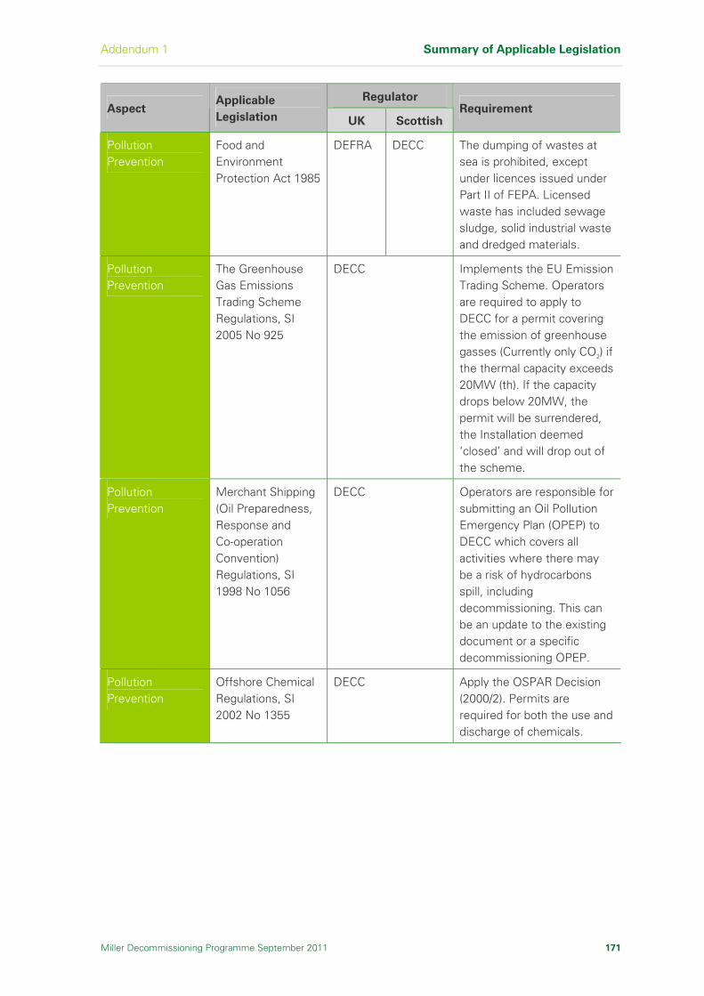
Addendum 1 Summary of Applicable Legislation
Miller Decommissioning Programme September 2011 171
Regulator Aspect
Applicable
Legislation UK Scottish Requirement
Pollution Prevention
Food and Environment Protection Act 1985
DEFRA DECC The dumping of wastes at sea is prohibited, except under licences issued under Part II of FEPA. Licensed waste has included sewage sludge, solid industrial waste and dredged materials.
Pollution Prevention
The Greenhouse Gas Emissions Trading Scheme Regulations, SI 2005 No 925
DECC Implements the EU Emission Trading Scheme. Operators are required to apply to DECC for a permit covering the emission of greenhouse gasses (Currently only CO2) if the thermal capacity exceeds 20MW (th). If the capacity drops below 20MW, the permit will be surrendered, the Installation deemed ‘closed’ and will drop out of the scheme.
Pollution Prevention
Merchant Shipping (Oil Preparedness, Response and Co-operation Convention) Regulations, SI 1998 No 1056
DECC Operators are responsible for submitting an Oil Pollution Emergency Plan (OPEP) to DECC which covers all activities where there may be a risk of hydrocarbons spill, including decommissioning. This can be an update to the existing document or a specific decommissioning OPEP.
Pollution Prevention
Offshore Chemical Regulations, SI 2002 No 1355
DECC Apply the OSPAR Decision (2000/2). Permits are required for both the use and discharge of chemicals.

Summary of Applicable Legislation Addendum 1
172 Miller Decommissioning Programme September 2011
Regulator Aspect
Applicable
Legislation UK Scottish Requirement
Pollution Prevention
The Offshore Combustion Installations (Prevention and Control of Pollution) Regulations, SI 2001 No 1091
DECC Implements the Integral Pollution Prevention and Control (IPPC) Directive for offshore oil and gas Installations requiring a permit when the aggregated thermal capacity exceeds 50MW (th). When below 50MW (th), the Operator will be required to surrender the permit.
Pollution Prevention
Offshore Petroleum Activities (Oil Pollution Prevention and Control) Regulations, SI 2005 No 2055
DECC Cover oil discharges and spills. Permits will be required to undertake any activity which could result in a spill or discharge of oil into the sea. They replace the Prevention of Oil Pollution Act 1971.
Pollution Prevention
Pollution Prevention and Control Act 1999, under which come PPC (England and Wales) Regulations (SI 2000 No 1973) and the PPC (Scotland) Regulations (SSI2000/323) as amended
EA SEPA Implements the European Commission (EC) Directive 96/61/EC on Integrated Pollution Prevention and Control (‘the IPPC Directive’), while building on the Environmental Protection Act 1990 (EPA 90). Requires Operators of Installations carrying out specified activities that may cause pollution or have other environmental effects, to submit an application for a permit.
Waste Management
Environment Protection (Duty of Care) Regulations, SI 1991 No 2839
EA SEPA All parties in the chain of waste will be required to ensure that all other parties act within the law.
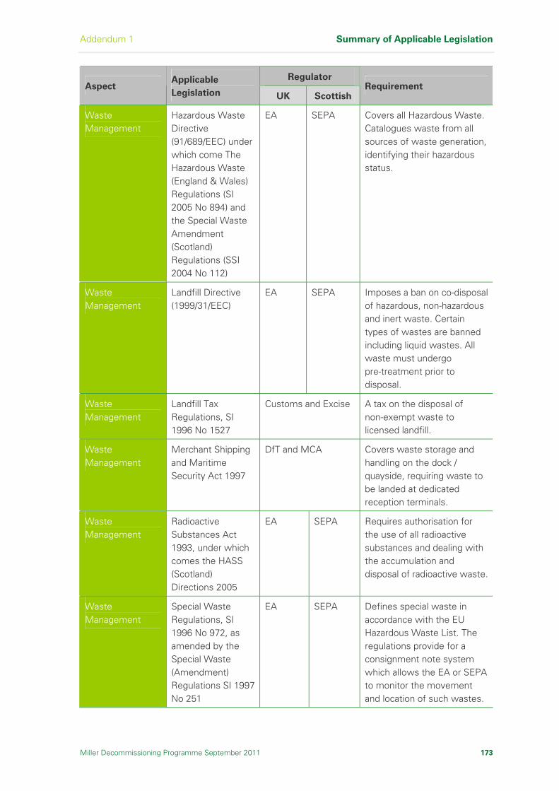
Addendum 1 Summary of Applicable Legislation
Miller Decommissioning Programme September 2011 173
Regulator Aspect
Applicable
Legislation UK Scottish Requirement
Waste Management
Hazardous Waste Directive (91/689/EEC) under which come The Hazardous Waste (England & Wales) Regulations (SI 2005 No 894) and the Special Waste Amendment (Scotland) Regulations (SSI 2004 No 112)
EA SEPA Covers all Hazardous Waste. Catalogues waste from all sources of waste generation, identifying their hazardous status.
Waste Management
Landfill Directive (1999/31/EEC)
EA SEPA Imposes a ban on co-disposal of hazardous, non-hazardous and inert waste. Certain types of wastes are banned including liquid wastes. All waste must undergo pre-treatment prior to disposal.
Waste Management
Landfill Tax Regulations, SI 1996 No 1527
Customs and Excise A tax on the disposal of non-exempt waste to licensed landfill.
Waste Management
Merchant Shipping and Maritime Security Act 1997
DfT and MCA Covers waste storage and handling on the dock / quayside, requiring waste to be landed at dedicated reception terminals.
Waste Management
Radioactive Substances Act 1993, under which comes the HASS (Scotland) Directions 2005
EA SEPA Requires authorisation for the use of all radioactive substances and dealing with the accumulation and disposal of radioactive waste.
Waste Management
Special Waste Regulations, SI 1996 No 972, as amended by the Special Waste (Amendment) Regulations SI 1997 No 251
EA SEPA Defines special waste in accordance with the EU Hazardous Waste List. The regulations provide for a consignment note system which allows the EA or SEPA to monitor the movement and location of such wastes.
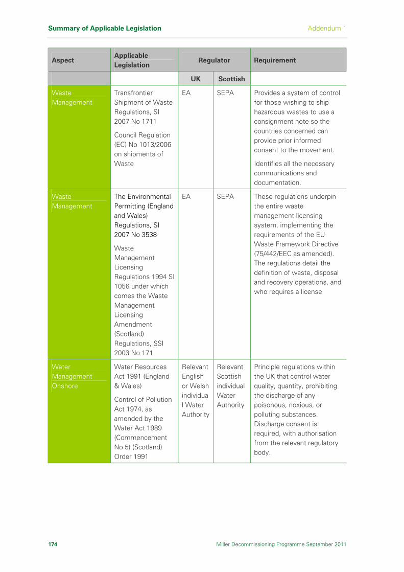
Summary of Applicable Legislation Addendum 1
174 Miller Decommissioning Programme September 2011
Aspect Applicable
Legislation Regulator Requirement
UK Scottish
Waste Management
Transfrontier Shipment of Waste Regulations, SI 2007 No 1711
Council Regulation (EC) No 1013/2006 on shipments of Waste
EA SEPA Provides a system of control for those wishing to ship hazardous wastes to use a consignment note so the countries concerned can provide prior informed consent to the movement.
Identifies all the necessary communications and documentation.
Waste Management
The Environmental Permitting (England and Wales) Regulations, SI 2007 No 3538
Waste Management Licensing Regulations 1994 SI 1056 under which comes the Waste Management Licensing Amendment (Scotland) Regulations, SSI 2003 No 171
EA SEPA These regulations underpin the entire waste management licensing system, implementing the requirements of the EU Waste Framework Directive (75/442/EEC as amended). The regulations detail the definition of waste, disposal and recovery operations, and who requires a license
Water Management Onshore
Water Resources Act 1991 (England & Wales)
Control of Pollution Act 1974, as amended by the Water Act 1989 (Commencement No 5) (Scotland) Order 1991
Relevant English or Welsh individual Water Authority
Relevant Scottish individual Water Authority
Principle regulations within the UK that control water quality, quantity, prohibiting the discharge of any poisonous, noxious, or polluting substances. Discharge consent is required, with authorisation from the relevant regulatory body.
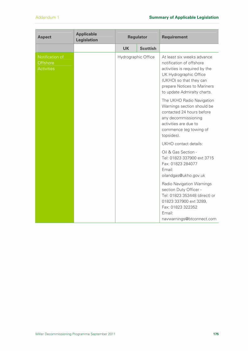
Addendum 1 Summary of Applicable Legislation
Miller Decommissioning Programme September 2011 175
Aspect Applicable
Legislation Regulator Requirement
UK Scottish
Notification of Offshore Activities
Hydrographic Office At least six weeks advance notification of offshore activities is required by the UK Hydrographic Office (UKHO) so that they can prepare Notices to Mariners to update Admiralty charts.
The UKHO Radio Navigation Warnings section should be contacted 24 hours before any decommissioning activities are due to commence (eg towing of topsides).
UKHO contact details:
Oil & Gas Section - Tel: 01823 337900 ext 3715 Fax: 01823 284077 Email: [email protected]
Radio Navigation Warnings section Duty Officer - Tel: 01823 353448 (direct) or 01823 337900 ext 3289, Fax: 01823 322352 Email: [email protected]

Summary of Applicable Legislation Addendum 1
176 Miller Decommissioning Programme September 2011
I n t e n t i o n a l l y L e f t B l a n k


![Shadowrun: Street Grimoire, 2nd Printing · HEALTH SPELLS 109 Ambidexterity 109 Alleviate Addiction 109 Alleviate [Allergy] 109 Awaken 109 ... Advanced Alchemy/ Ritual/Spellcasting](https://img.pdfslide.net/doc/110x75/5f0367d57e708231d4090d07/shadowrun-street-grimoire-2nd-printing-health-spells-109-ambidexterity-109-alleviate.jpg)