Embed Size (px)
Citation preview
MIMAKI ENGINEERING CO., LTD.URL: http://mimaki.com/
You can also download the latest manual from our website.
D202746-16Original instructions
i
CAUTION .......................................................................................viiDISCLAIMER OF WARRANTY ...........................................................viiRequests .............................................................................................viiFCC Statement (USA) .........................................................................viiInterference to televisions and radios ..................................................vii
Foreword ........................................................................................viiAbout usable ink ..................................................................................viiOn This Operation manual ..................................................................vii
Safety Precautions ........................................................................ viiiSymbols ..............................................................................................viii
Warning labels ................................................................................xiEC DECLARATION OF CONFORMITY .............................................xiii
Chapter 1 Before Use
Moving This Machine ................................................................... 1-2Where to Install This Machine ........................................................... 1-2Working Environmental Temperature................................................ 1-2Moving This Machine ........................................................................ 1-2
Names of Parts and Functions .................................................... 1-3Front Side of the Machine ................................................................. 1-3Rear Side and Right Side of the Machine ......................................... 1-4Operation Panel ................................................................................ 1-5Media sensor..................................................................................... 1-7Carriage............................................................................................. 1-7Cutter blade and slot for cutting ........................................................ 1-7Capping station ................................................................................. 1-7Pinch Rollers and Grit Rollers ........................................................... 1-7
Connecting Cables ...................................................................... 1-8Connecting USB2.0 Interface Cable ................................................. 1-8Connecting the power cable.............................................................. 1-8
Inserting ink cartridges ................................................................. 1-9Caution in handling of ink cartridges ............................................... 1-10
Media ......................................................................................... 1-10Usable sizes of media ..................................................................... 1-10Caution in handling of medias ......................................................... 1-10
Menu mode ................................................................................ 1-11
Chapter 2 Basic Operations
Workflow of printing ..................................................................... 2-2Turning the Power ON/OFF ......................................................... 2-3
Turning the Power ON....................................................................... 2-3Turning the Power OFF..................................................................... 2-3
Table of Contents
ii
Setting a Media ............................................................................2-4Adjusting the Head Height................................................................. 2-4Adjusting the Position of the Pinch Roller According to the State of a Media ................................................................................ 2-5Maximum Print Area/Cut Area........................................................... 2-8Notes When Using media Holder ...................................................... 2-8Setting a roll media............................................................................ 2-9Setting the pinch roller pressure...................................................... 2-11Take-up device................................................................................ 2-12Setting leaf media............................................................................ 2-13Changing the printing origin ............................................................ 2-14
Preparing for the Heaters ...........................................................2-14Changing the Temperature Settings for the Heaters....................... 2-14
Test Printing ...............................................................................2-15Test Printing .................................................................................... 2-15Perform test printing with the normal test pattern............................ 2-16Perform test printing with the test pattern for checking white ink .... 2-16
Head Cleaning ...........................................................................2-17About head cleaning........................................................................ 2-17Perform head cleaning depending on the test printing result .......... 2-17
Setting of Media Correction ........................................................2-17Setting of Media Correction............................................................ 2-17
If the Positions of Dots Shift... ....................................................2-18Printing Data ..............................................................................2-18
Starting a Printing Operation ........................................................... 2-18Stopping a Printing Operation ......................................................... 2-19Deleting Received Data (Data Clear) .............................................. 2-19
Cutting a media ..........................................................................2-19Workflow of cutting .....................................................................2-20Installing Tools ...........................................................................2-21
When a Cutter Is Used .................................................................... 2-21How to Install a Ballpoint Pen.......................................................... 2-22
Setting the cutting conditions .....................................................2-24About the Cut Conditions ................................................................ 2-24Select the tool condition .................................................................. 2-24Set the Cut Conditions .................................................................... 2-25
Test Cutting ................................................................................2-26Cutting Data ...............................................................................2-26
Setting the origin ............................................................................. 2-26Start cutting ..................................................................................... 2-26Stopping a Cutting Operation (Data Clear) ..................................... 2-27Removing the Cutter Unit Temporarily ............................................ 2-27
Cutting a media ..........................................................................2-27

iii
Chapter 3 Setup
About SETUP MENU ................................................................... 3-2SETUP MENU table .......................................................................... 3-3Register the optimal print conditions to match the use...................... 3-4Setting of Media Correction............................................................... 3-5If the Positions of Dots Shift... ........................................................... 3-6Setting the HEATER.......................................................................... 3-6Setting of Logical Seek...................................................................... 3-7Setting of Drying Time....................................................................... 3-7Setting of Left and Right Margins ...................................................... 3-8Setting of Vacuum Fan...................................................................... 3-8Setting of Feed Speed....................................................................... 3-8Setting of MAPS................................................................................ 3-8Setting Auto Cleaning........................................................................ 3-9Setting Interval wiping ....................................................................... 3-9
About MACHINE SETUP MENU ............................................... 3-10MACHINE SETUP MENU table ...................................................... 3-11Setting a AUTO Power-off............................................................... 3-12Setting Take-up unit ........................................................................ 3-12Setting Top Blower .......................................................................... 3-12Setting the Display of Media Residual............................................. 3-13Setting the Display of Media Detection ........................................... 3-13Setting a LANGUAGE ..................................................................... 3-14Setting Time .................................................................................... 3-14Setting Unit (Temperature/ Length)................................................. 3-14Setting a KEY BUZZER................................................................... 3-14Setting the CONFIRM. FEED.......................................................... 3-15Setting the SPACE FEED MODE.................................................... 3-15Set the network ............................................................................... 3-15Setting event mail function .............................................................. 3-16Initializing the Settings..................................................................... 3-20
About NOZZLE CHECK MENU ................................................. 3-21INFORMATION MENU table........................................................... 3-21Printing Check Flow ........................................................................ 3-22Printing Operations at “Nozzle Missing” Judgment and Error Occurrence...................................................................................... 3-22Setting the Printing Check............................................................... 3-23Setting the NOZZLE RECOVERY................................................... 3-23Setting the Judgement Condition .................................................... 3-23
About INFORMATION MENU .................................................... 3-24INFORMATION MENU table........................................................... 3-25Displaying the Information............................................................... 3-25

iv
Chapter 4 Cutting Funcion
Cut Out Data with Registration Mark ............................................4-2The Flow of Cutting out the Registered Data .................................... 4-2Enter the registration mark detection mode ...................................... 4-2Precautions in inputting data with registration marks ........................ 4-2Setting of Detecting the Registration Marks ...................................... 4-6
About CUTTING MENU ...............................................................4-8Cutting MENU table........................................................................... 4-9
Setting the CUT MODE ..............................................................4-10perform multiple Cuttings (Copy function) ..................................4-10SETUP SUB MENU ...................................................................4-11
Setting the DIVISION CUT .............................................................. 4-11Make the media without uncut area (OVER CUT function) ............. 4-13Other SETUP SUB MENU .............................................................. 4-13SETUP RESET ............................................................................... 4-14
Maintenance Function ................................................................4-14Maintenance of Mark Sensor .......................................................... 4-15Perform SAMPLE CUT to Find out the Cause of Cutting Error. ...... 4-17Cutting a Medium into Multiple Pieces with a Certain Length ......... 4-17Cutting out Data without Register Marks (PC ORIGIN OFFSET).... 4-18Setting the Scale Adjust .................................................................. 4-19
Chapter 5 Maintenance
Maintenance ................................................................................5-2Precautions for Maintenance............................................................. 5-2About Cleaning Solution ....................................................................5-2Cleaning the Exterior Surfaces.......................................................... 5-2Cleaning the Platen ........................................................................... 5-2Cleaning the Media Sensor ............................................................... 5-3Cleaning the Media Press ................................................................. 5-3
About MAINTENANCE MENU .....................................................5-4MAINTENANCE MENUs at-a-glance................................................ 5-5
Maintaining the Capping Station ..................................................5-6Cleaning the Wiper and Cap ............................................................. 5-6Washing the Head Nozzle................................................................. 5-7Washing the Ink Discharge Passage ................................................ 5-8When the Machine Is Not Used for a Long Time .............................. 5-8
Cleaning the Ink Head and the Area around It ...........................5-10Nozzle Recovery Function .....................................................................5-11
Reset the set value.......................................................................... 5-12Automatic Maintenance Function ...............................................5-12
Setting the Refreshing Intervals ...................................................... 5-13Setting the Tube Wash Intervals ..................................................... 5-13Setting the Cleaning Intervals and Type ......................................... 5-13
Fill up Ink ....................................................................................5-14White Ink Maintenance ...............................................................5-14

v
Replacing consumables ............................................................. 5-15Replacing the wiper......................................................................... 5-15If a Waste Ink Tank Confirmation Message Appears ...................... 5-15Replacing the waste ink tank before the waste ink tank confirmation message is displayed ................................................. 5-17Replacing the Cutter Blade ............................................................. 5-17
Replacing and Adjusting the Cutter Blade ................................. 5-18Replacing the cutter ........................................................................ 5-18Adjusting the Cutter Blade............................................................... 5-18Replacing the cutter other than supplied one.................................. 5-18Adjusting blade edge of cutter other than supplied one .................. 5-19
Chapter 6 Troubleshooting
Troubleshooting ........................................................................... 6-2Power does not turn on ..................................................................... 6-2The machine does not start printing .................................................. 6-2Media get jammed / media is soiled .................................................. 6-2The heater’s temperature will not rise to the set level ....................... 6-3Image quality is poor ......................................................................... 6-3Nozzle is clogged .............................................................................. 6-3Ink cartridge warning appears ........................................................... 6-4When the ink leakage occurs ............................................................6-4
Warning / Error Messages ........................................................... 6-5Warning messages............................................................................ 6-5Error messages................................................................................. 6-8
Chapter 7 Appendix
Specifications ............................................................................... 7-2Printer Section Specifications............................................................ 7-2Cutter Section Specifications ............................................................ 7-2Common Specifications..................................................................... 7-3Ink specifications ............................................................................... 7-4
Setting orders depending on ink type .......................................... 7-5Sheet for inquiry ........................................................................... 7-6

vi

vii
CAUTION
CAUTIONDISCLAIMER OF WARRANTY
THIS LIMITED WARRANTY OF MIMAKI SHALL BE THE SOLEAND EXCLUSIVE WARRANTY AND IS IN LIEU OF ALLOTHER WARRANTIES, EXPRESS OR IMPLIED, INCLUDING,BUT NOT LIMITED TO, ANY IMPLIED WARRANTY OFMERCHANTABILITY OR FITNESS, AND MIMAKI NEITHERASSUMES NOR AUTHORIZES DEALER TO ASSUME FOR ITANY OTHER OBLIGATION OR LIABILITY OR MAKE ANYOTHER WARRANTY OR MAKE ANY OTHER WARRANTY INCONNECTION WITH ANY PRODUCT WITHOUT MIMAKI’SPRIOR WRITTEN CONSENT.IN NO EVENT SHALL MIMAKI BE LIABLE FOR SPECIAL,INCIDENTAL OR CONSEQUENTIAL DAMAGES OR FORLOSS OF PROFITS OF DEALER OR CUSTOMERS OF ANYPRODUCT.
Requests
• This Operation manual has been carefully prepared foryour easy understanding. However, please do not hesitate to contact a distributorin your district or our office if you have any inquiry.
• Description contained in this Operation manual aresubject to change without notice for improvement.
FCC Statement (USA)
This equipment has been tested and found to comply with thelimits for a Class A digital device, pursuant to Part 15 of the FCCRules. These limits are designed to provide reasonableprotection against harmful interference when the equipment isoperated in a commercial environment. This equipmentgenerates, uses and can radiate radio frequency energy and, ifnot installed and used in accordance with the Operation manual,may cause harmful interference to radio communications.Operation of this equipment in a residential area is likely tocause harmful interference in which case the user will berequired to correct the interference at his own expense.In the case where MIMAKI-recommended cable is not used forconnection of this device, limits provided by FCC rules can beexceeded.To prevent this, use of MIMAKI-recommended cable is essentialfor the connection of this machine.
Interference to televisions and radios
The product described in this manual generates high frequencywhen operating.The product can interfere with radios and televisions if set up orcommissioned under improper conditions.The product is not guaranteed against any damage to specific-purpose radio and televisions.The product’s interference with your radio or television will bechecked by turning on/off the power switch of the product.In the event that the product is the cause of interference, try toeliminate it by taking one of the following corrective measures ortaking some of them in combination.
• Change the orientation of the antenna of the television set orradio to find a position without reception difficulty.
• Separate the television set or radio from this product.• Plug the power cord of this product into an outlet which is
isolated from power circuits connected to the television set orradio.
ForewordCongratulations on your purchase of MIMAKI color ink jetprinter "CJV300-130/160" .“CJV300-130/160” is a color inkjet printer that can print on1.3m or 1.6m-width media with solnent ink (4-color, 6-color and 8-color) and sublimation dye ink (4-color and 6-color) realizing high image quality.
About usable ink
You can use solvent ink (SS21/ES3) and sublimation dyeink (Sb53/Sb54) for this machine.
On This Operation manual
• This Operation manual is describing the operationsand maintenance of "Color inkjet printer CJV300-130/160" (called as this machine hereafter)
• Read this Operation manual carefully and understandthem thoroughly to use.
• It is also necessary to keep this Operation manual onhand.
• This Operation manual has been carefully prepared foryour easy understanding, however, please do nothesitate to contact a distributor in your district or ouroffice if you have any inquiry.
• Descriptions contained in this Operation manual aresubject to change without any notice for improvement.
• In the case when this Operation manual should beillegible due to destruction or lost by fire or breakage,purchase another copy of the Operation manual fromour office.
• You can also download the latest manual from ourwebsite.
Reproduction of this manual is strictly prohibited.All Rights Reserved.Copyright© 2016 MIMAKI ENGINEERING Co., Ltd.

viii
1
2
2
2
2
2
1
Safety Precautions
Safety PrecautionsSymbols
Symbols are used in this Operation Manual for safeoperation and for prevention of damage to the machine.The indicated sign is different depending on the content ofcaution.Symbols and their meanings are given below. Pleasefollow these instructions as you read this manual.
Examples of symbols
Warning for Use
Meaning
Failure to observe the instructions given withthis symbol can result in death or seriousinjuries to personnel. Be sure to read it carefullyand use it properly.
Failure to observe the instructions given withthis symbol can result in injuries to personnel ordamage to property.
Important notes in use of this machine aregiven with this symbol. Understand the notesthoroughly to operate the machine properly.
Useful information is given with this symbol.Refer to the information to operate the machineproperly.
Indicates the reference page for relatedcontents.
The symbol " " indicates that the
instructions must be observed as strictly as theCAUTION instructions (including DANGER andWARNING instructions). A sign representing aprecaution (the sign shown at left warns ofhazardous voltage) is shown in the triangle.
The symbol " " indicates that the action
shown is prohibited. A sign representing aprohibited action (the sign shown at leftprohibits disassembly) is shown in or aroundthe circle.
The symbol " " indicates that the action
shown must be taken without fail or theinstructions must be observed without fail. Asign representing a particular instruction (thesign shown at left instructs to unplug the cablefrom the wall outlet) is shown in the circle.
WARNING
• The set of power cables provided with this machine isfor use with this machine only, and cannot be usedwith other electrical devices. Do not use any powercables other than the ones provided with the machine.Failure to observe those instructions may result in fireor electric shocks.
• Do not use this machine in an environment wherehumidity is high or the machine may get wet. Using themachine under such environment may result in fire orelectric shock, or cause malfunction.
• Use of the machine under an abnormal conditionwhere it produces smoke or strange smell can result infire or electric shocks. If such an abnormality is found,be sure to turn off the power switch immediately andunplug the cable from the wall outlet. Check first thatthe machine no longer produces smoke, and contactyour distributor or a sales office of MIMAKI for repair.
• Never repair your machine by yourself since it is verydangerous for you to do so.
• Never disassemble or remodel the main unit of themachine or the ink cartridge. Disassembly orremodeling can result in an electric shock orbreakdown of the machine.
• Take care that no dust or dirt sticks to Media TransferSurface heaters. Dust and dirt sticking heaters cancause fire.
• Do not use extension cords. Doing so may result in fireor electric shocks.
• Keep the power plug prong clear of any foreign objectsuch as a piece of metal. Failure to do so may result ina fire or electric shocks.
• Do not plug too may leads into a single socket. Doingso may result in fire or electric shocks.
• Do not use the machine if the power cord or plug isdamaged. Using the machine with damaged powercord may result in fire or electric shocks. Contact yourservice representative for replacement cord.
• Do not handle the power plug with wet hands. Doingso may result in electric shocks.
• Grasp by holding the plug itself when removing thepower plug from wall outlet, and never hold by thecord. Holding and pulling the cord may damage thecord, leading to fire or electric shocks.
• In case of ink leakage, please turn off the main power,unplug the power cable and contact our service officeor distributor.
Hazardous Moving Parts• Keep Fingers and Other Body Parts Away
• If a foreign object such as a small piece of metal or aliquid such as water gets inside the machine, turn offthe machine and unplug the power cord immediately,then consult your service representative. Continuing touse the machine without proper maintenance or repairmay result in fire or electric shocks.
• Do not use a flammable spray or solvent inside oraround the machine. Doing so may result in fire orelectric shocks.
• Do not place a vase, flower pot, water glass, containerwith liquid such as water or chemicals inside, or smallmetallic object near or on top of this machine. Liquid orforeign object may get inside the machine, leading tofire or electric shocks.

ix
Safety Precautions
Precautions in Use
CAUTIONS and NOTES
CAUTION
Handling of the power cable
• Connect to a socket-outlet with determinate polarity.
• For Inlet 1 and 2, be sure to supply power from theoutlet of the same voltage.
• For PLUGGABLE EQUIPMENT, the socket-outlet shallbe installed near the equipment and shall be easilyaccessible.
• Unplug the cord from the wall outlet and remove dustfrom the power plug periodically, at least once a year.Failure to do so may result in fire or electric shocks.
• Do not use the machine unless it is connected to apower supply that satisfies the displayed voltagecondition.
• Check the voltage of the wall outlet and the capacity ofthe circuit breaker before you plug the power cords.Plug each power cord to different outlet that hasindependent circuit breaker. If you plug more than onepower cord to wall outlets that share the same circuitbreaker, the power may be cut off by the breaker.
Handling of ink
• Keep ink away from an open flame. Also keep theroom well ventilated when you use or handle ink.
• If you get ink in your eyes, immediately wash youreyes with a lot of clean water for at least 15 minutes. Indoing so, also wash eyes to rinse ink away completely.Then, consult a doctor as soon as possible.
• If anyone drinks ink by mistake, keep him or her quietand see a doctor immediately. Do not allow him or herto swallow the vomit.Then contact the emergency number written in SDS.
• If you inhale a lot of vapor and feel bad, immediatelymove to a location of fresh air and keep yourself warmand quiet. Then, consult a doctor as soon as possible.
• Store ink cartridges in a place that is out of the reach ofchildren.
• If the ink adheres to your skin, use a large amount ofwater and soap or special detergent for skin to removethe ink.
Power supply
• Leave the breaker turned ON.• Do not turn off the main power switch on the right side
of this machine.
Heater
• Do not spill liquid on the Media Transfer Surface asthis may cause failure of the heater or firing.
• Do not touch Media Transfer Surface heaters with barehand while it is hot; otherwise, you can get burned.
Note on maintenance
• When cleaning the heads, make sure to wear theattached goggles and gloves.
• The gloves supplied with the machine are disposable.When all the gloves are expended, purchase anequivalent product on the market.
• Keep ink away from an open flame. Also keep theroom well ventilated when you use or handle ink.
Caution with cutters
• Do not touch the cutter blade, which is very sharp.• Do not shake or swing the cutter holder; otherwise, the
blade may come off.
Be careful with the movable parts
• Do not touch the rolling grit roller; otherwise, you mayhurt your fingers or tear off your finger nails.
• Keep your head and hands away from any movingparts during cutting (plotting) operation; otherwise, youmay get your hair caught in the machine or get injuries.
• Wear proper clothes. (Do not wear loose-fit clothes oraccessories). Bind a long hair.
Warning
Handling of ink cartridges
• The safety evaluation of this machine assumes that the inkrecommended by this company is used. For safe usage of thismachine, use the ink recommend by this company
• Never refill the ink pack and white ink cartridge with ink. Refilledink cartridge can cause a trouble. Remember that MIMAKIassumes no responsibility for any damage caused by the use ofthe ink cartridge replenished with ink.
• If the ink cartridge is moved from a cold place to a warm place,leave it in the room temperature for three hours or more beforeusing it.
• Open the ink cartridge just before installing it in the machine. If itis opened and left for an extended period of time, normalprinting performance of the machine may not be ensured.
• Make sure to store ink cartridges in a cool and dark place.
• Store ink cartridges and waste ink bottle in a place that is out ofthe reach of children.
• Be sure to thoroughly consume the ink in the ink cartridge, onceit is opened, within three months. If an extended period of timehas passed away after opening the cartridge tank, printingquality would be poor.
• Neither pound the cartridge nor shake it violently, as doing socan cause leakage of ink.
• Do not touch or stain the contacts of the ink cartridge, as doingso may cause damage to the print circuit board.
• Consult your sales or service representative for proper disposalof ink cartridge, ink pack, and waste ink.When you dispose them by yourself, follow the regulationsstipulated by the industrial waste disposer or the country orregion you live in.
• Make sure that you shake the white and silver ink cartridgesbefore printing.
Clump lever
• Never raise the lever during printing. Raising the lever will abortprinting.
Protection of media from dust
• Store media in a bag. Wiping off dust accumulated on media willadversely affect the media due to static electricity.
• When leaving the workshop after the working hours, do notleave any media on the roll hanger. If any media is left on the rollhanger, it can get dusty.
Disposition of this machine
• Consult your sales or service representative for proper disposalof this machine. Otherwise, commission an industrial wastedisposal company.
CAUTION

x
1
2
2
2
2
2
1
Safety Precautions
Cautions on Installation
Periodic replacement parts
• Some parts of this machine must be replaced with a new oneperiodically by service personnel. Be sure to make a contractwith your distributor or dealer for After sale service to ensure along life of your machine.
Notes on maintenance
• It is strongly recommended to use the machine in a room that isnot dusty.
• Keep the front cover closed even when the machine is notprinting. If not, dust can accumulate on the nozzles in theheads.
• Dust in the heads can also cause drops of ink to fall suddenlydown on the media during printing. In such a case, be sure toclean up the heads. ( P.5-10)
• When cleaning the ink-station or the heads, make sure to wearthe attached gloves. Further, when the solvent ink is used, it isnecessary to wear the attached goggles.
• Perform wiping (removal of dust and paper powder) of thecapping station and wiper frequently.
Handling of media
• Use media recommended by MIMAKI to ensure reliable, high-quality printing.
• Set the heater temperature to meet the characteristics of themedia. (Model with a built-in heater)Set the temperature of the Pre-heater, Print heater and Post-heater according to the type and characteristics of the mediaused. Automatic temperature setting can be made on theoperation panel by setting the profile on the dedicated RIP. Forsetting on the RIP, refer to the instruction manual for your RIP.
• Pay attention to the expansion and contraction of the media.Do not use media immediately after unpacking. The media canbe affected by the room temperature and humidity, and thus itmay expand and contract.The media have to be left in theatmosphere in which they are to be used for 30 minutes or moreafter unpacked.
• Do not use curled media.The use of curled media can not only cause a media jam butalso affect print quality.Straighten the sheet of media, if significantly curled, beforeusing it for printing. If a regular-sized coated sheet of media isrolled and stored, the coated side has to face outside.
• Do not leave the media with the heater ON for a long time.
Warning
CAUTION
A place exposed to directsunlight
On an inclined surface
A place that vibratesA place exposed to direct airflow from an air conditioneror the like.
A place where temperature orhumidity varies significantly
Around a place where fireis used
•Use the machine under the following environmental conditions:
•Operating environment:20 to 30 °C (68 to 86 °F)35 to 65 % (Rh)
xi
Warning labels
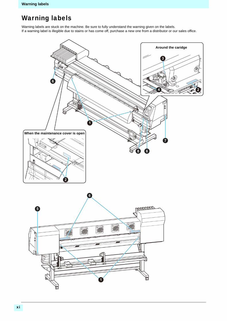
Warning labelsWarning labels are stuck on the machine. Be sure to fully understand the warning given on the labels.If a warning label is illegible due to stains or has come off, purchase a new one from a distributor or our sales office.
Around the caridge
When the maintenance cover is open

xii
Warning labels
1
2
2
2
2
2
1
No. Reorder Label
1 M903239
2 M903330
3 M903405
4 M906144
5 M907935
6 M905811
7 M906031
8 M905935

xiii
Warning labels
EC DECLARATION OF CONFORMITY
We hereby declare that the following our product conforms with the essential health and safety requirements of ECDirectives.
Product Inkjet Printer
Model No. CJV300-160CJV300-130
Manufacturer MIMAKI ENGINEERING CO.,LTD.2182-3, Shigeno-otsu, Tomi, Nagano, 389-0512, JAPAN
Authorised Compiler in the CommunityMIMAKI EUROPE B.V.Stammerdijk 7E 1112 AA Diemen, The Netherlands
Directives Machinery Directive2006/42/ECLow Voltage Directive2014/35/EUEMC Directive2014/30/EURoHS Directive2011/65/EU
The above product has been evaluated for conformity with above directives using the following European standards. Thetechnical construction file (TCF) for this product is retained at the above Manufacturer’s location.
Machinery Directive / Low Voltage DirectiveENISO12100:2010, EN60204-1:2006+A1,EN60950-1:2006+A11+A1+A12
EMC Directive EN55022:2010, EN61000-3-2:2006+A1+A2, EN61000-3-3:2008, EN55024:2010
RoHS Directive EN50581:2012
This chapter
describes the items required to understand before use, such as the name of each part ofthe machine or the installation procedures.
Moving This Machine .................................... 1-2Where to Install This Machine ..................... 1-2Working Environmental Temperature ......... 1-2Moving This Machine .................................. 1-2
Names of Parts and Functions...................... 1-3Front Side of the Machine ........................... 1-3Rear Side and Right Side of the Machine ... 1-4Operation Panel .......................................... 1-5Media sensor ............................................... 1-7Carriage ...................................................... 1-7Cutter blade and slot for cutting .................. 1-7Capping station ........................................... 1-7Pinch Rollers and Grit Rollers ..................... 1-7
Connecting Cables........................................ 1-8Connecting USB2.0 Interface Cable ............1-8Connecting the power cable ........................1-8
Inserting ink cartridges .................................. 1-9Caution in handling of ink cartridges ..........1-10
Media .......................................................... 1-10Usable sizes of media ................................1-10Caution in handling of medias ...................1-10
Menu mode ................................................. 1-11
Chapter 1
Before Use

Chapter 1 Before Use
1-2
Moving This MachineWhere to Install This Machine
Secure a suitable installation space before assemblingthis machine.The place of installation must have enough space for notonly this machine itself, but also for the printing operation.
Working Environmental Temperature
Use this machine in an environment of 20 to 30C toensure reliable printing.
Moving This Machine
Move this machine according to the following steps whenthis machine needs to be moved on the same step-freefloor.
1 Remove the caster blocks.
2 Move this machine as shown in the figure.
• For safety, be sure to operate it with 4 people ormore.
• Do not push the cover to move this machine sincethe cover may be broken.
3 Reinstall the caster blocks.
Model Width Depth HeightGross weight
CJV300-1302525mm
(99.4in)700mm(27.6in)
1392mm(54.8in)
157kg(346.1lb)
CJV300-1602775mm(109.3in)
700mm(27.6in)
1392mm(54.8in)
168kg(370.4ib)
500 mm or more(19.7 in or more)
3525 mm or more (130 model)
(138.8 in or more (130 model))
3775 mm or more (160 model)
(148.6 in or more (160 model))
2700 mm or more
(106.3 in or more)
500 mm or more(19.7 in or more)
1000 mm or more
(39.3 in or more)
1000 mm or more
(39.3 in or more)
• When the machine is moved to any place other than on the same step-free floor, contact your distributor or our service office.If you move it by yourself, failure or damage may occur. Be sure to request your distributor or our service office to move this machine.
• When moving this machine, take care that it does not receive a significant impact.
• Be sure to lock the casters after moving of this machine.

1-3
Chapter 1 Before Use
1
2
2
2
2
Names of Parts and FunctionsFront Side of the Machine
Operation panel
This panel has the operation keys required for operating the machine and the LCDs for displaying setting items, etc.
Clamp lever (front)
Moves the pinch rollers up and down to hold or release the media.
Waste ink tank
Waste ink gathers in this tank.
Stand
Supports the main body of the machine. It is provided with casters that are used to move this machine.
Platen
The printed media is sent out, sliding on the platen.
Ink cartridgesEach cartridge contains an ink of a particular color.
Cartridge protection coverThis prevents an injury or breakage of the machine due to a protrusion of the ink cartridge. (It is located under the ink cartridge.)
Take-up device
Automatically winds up the roll media printed.
Carriage
Move the print head unit from side to side.
Maintenance cover
Open the cover in maintenance.Even when the power switch is off, keep all covers closed.
CleaningSolutionCartridge slot
Insert the cleaning solution cartridge.
Top blower
Dries ink by blowing air from the ceiling part.

1-4
Chapter 1 Before Use
Rear Side and Right Side of the Machine
AC inlet
Connect the power cable to the AC inlet.
Clamp lever (rear)
Interlocks with the clamp leverin the font of this machine.
USB 2.0 connector
This is USB2.0 interface connector.
Main power switch (INLET 1)
Turns on/off the main power for this machine. Leave the main power turned on to prevent ink clogging.
Top blower filter
Suppress upward floating of the ink mist that occurs during
Vent filter box
Vents the ink mist that occurs during printing.
Roll holders
Putting this into the paper core (right and left) of a roll media, hold the media. It supports the paper core of 2 inch and 3 inch.
Power switch for heater (INLET 2)
Turns on/off the heater for this machine.
LAN connector
Please use this connector when you use netwark function.
1-5
Chapter 1 Before Use
1
2
2
2
2
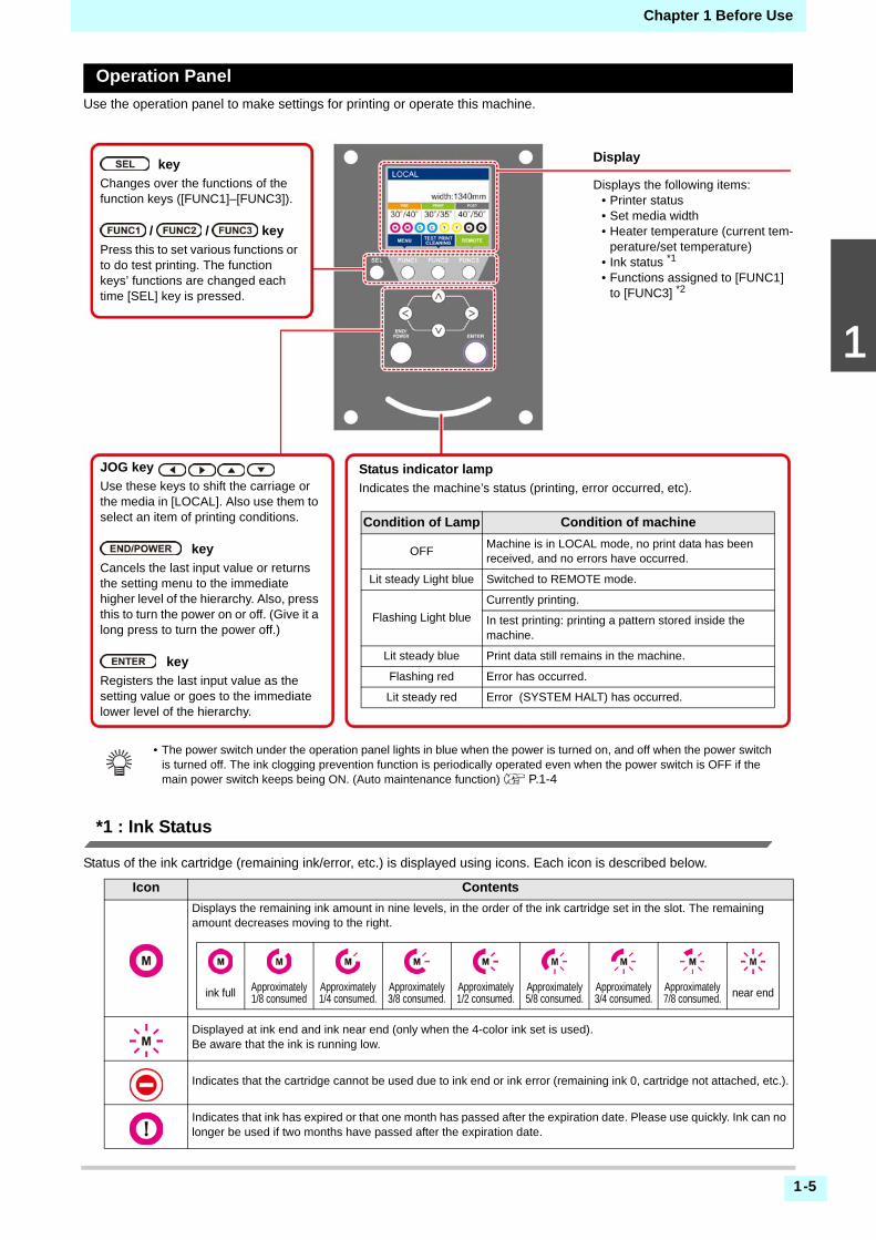
Operation Panel
Use the operation panel to make settings for printing or operate this machine.
*1 : Ink Status
Status of the ink cartridge (remaining ink/error, etc.) is displayed using icons. Each icon is described below.
Icon Contents
Displays the remaining ink amount in nine levels, in the order of the ink cartridge set in the slot. The remaining amount decreases moving to the right.
Displayed at ink end and ink near end (only when the 4-color ink set is used).Be aware that the ink is running low.
Indicates that the cartridge cannot be used due to ink end or ink error (remaining ink 0, cartridge not attached, etc.).
Indicates that ink has expired or that one month has passed after the expiration date. Please use quickly. Ink can no longer be used if two months have passed after the expiration date.
Status indicator lamp
Indicates the machine’s status (printing, error occurred, etc).
Condition of Lamp Condition of machine
OFFMachine is in LOCAL mode, no print data has been received, and no errors have occurred.
Lit steady Light blue Switched to REMOTE mode.
Flashing Light blue
Currently printing.
In test printing: printing a pattern stored inside the machine.
Lit steady blue Print data still remains in the machine.
Flashing red Error has occurred.
Lit steady red Error (SYSTEM HALT) has occurred.
Display
Displays the following items:• Printer status• Set media width• Heater temperature (current tem-
perature/set temperature)• Ink status *1
• Functions assigned to [FUNC1] to [FUNC3] *2
key
Changes over the functions of the function keys ([FUNC1]–[FUNC3]).
/ / key
Press this to set various functions or to do test printing. The function keys’ functions are changed each time [SEL] key is pressed.
JOG key
Use these keys to shift the carriage or the media in [LOCAL]. Also use them to select an item of printing conditions.
key
Cancels the last input value or returns the setting menu to the immediate higher level of the hierarchy. Also, press this to turn the power on or off. (Give it a long press to turn the power off.)
key
Registers the last input value as the setting value or goes to the immediate lower level of the hierarchy.
• The power switch under the operation panel lights in blue when the power is turned on, and off when the power switch is turned off. The ink clogging prevention function is periodically operated even when the power switch is OFF if the main power switch keeps being ON. (Auto maintenance function) P.1-4
ink full Approximately 1/8 consumed
Approximately 1/4 consumed.
Approximately 3/8 consumed.
Approximately 1/2 consumed.
Approximately 5/8 consumed.
Approximately 3/4 consumed.
Approximately 7/8 consumed. near end

1-6
Chapter 1 Before Use
*2 : Functions assigned to [FUNC1] to [FUNC3]
Contents of functions assigned to [FUNC1] to [FUNC3] are described below.
Icon Contents
Displays “MENU” for setting functions.
Displays maintenance functions such as test print, cleaning, etc.
Shifts to REMOTE from LOCAL and starts printing.
Displays adjustment functions such as FEED COMP, DROP.POScorrect, etc.
Sets the heater temperature.
Executes data clear.
Suspends printing in REMOTE and shifts to LOCAL.
Executes media cut.
When there are multiple items on the MENU screen or other screens, it moves to the previous page.
When there are multiple items on the MENU screen or other screens, it moves to the next page.
Used for completing confirmation when warning message has been displayed and so on.
Used for turning functions OFF or cancelling them, for example, when turning heater settings OFF and so on.
Some kind of setting or function is assigned. Operate according to the description of each function.
Switches between enable/disable when selecting multiple items, for example, when selecting target head for cleaning and so on.
Set the cutting conditions.
Check or set the settings related to cutting, such as test cutting.
Set the pressure of the pinch rollers.
• The color of icons changes according to the state of the printer.When the icon is green : The printer is in REMOTE mode.When the icon is dark blue : The printer is in LOCAL mode.When the icon is yellow : A warning has been issued.When the icon is red : An erroe has been issued.

Chapter 1 Before Use
1-7
1
2
2
2
2
Media sensor
The media sensor detects the presence of the media andthe media length.This machine has one media sensor on the platen (in therear).
Carriage
The carriage consists of the printer unit and the cutterunit.
Printer Unit
Cutter Unit
Cutter blade and slot for cutting
The carriage is provided with a cutter unit for cutting offthe media that has been printed on. The cutter cuts off the sheet of media along the slot forcutting on the platen.
Capping station
The capping station consists of the ink caps, the wiper forcleaning the heads, etc.The ink caps prevent the nozzles in the ink heads fromdrying up.The wiper cleans the nozzles in the heads.The wiper is consumable.If the wiper is deformed or themedia is stained, replace the wiper with a new one.
Pinch Rollers and Grit Rollers
This machine retains the media with the pinch rollers andthe grit rollers.
• When setting a media, be sure to cover the media sensors located on the rear of the platen. The media cannot be detected unless it is placed over the sensor.
Media sensor
Printer unit
Cutter unit
• Be sure to wear the attached goggles in cleaning within the capping station to protect your eyes against ink. Otherwise, you may get ink in your eyes.
• Keep the pinch rollers lifted up when this machine is not in use. If the pinch rollers are left lowered for an extended period of time, they can be deformed and fail to securely retain the media.
Cutter partslot for cutting
Grit roller Pinch roller

Chapter 1 Before Use
1-8
Connecting CablesConnecting USB2.0 Interface Cable
Connect the PC and this machine with the USB2.0interface cable.
Notes on USB 2.0 Interface
When two or more CJV300 machines are connected to one personal computer
When two or more CJV300 machines are connected toone personal computer, the personal computer may notrecognize all the CJV300 machines normally.Reconnect the unrecognized CJV300 machine to anotherUSB port, if available, and check to see if it isrecognized.If the CJV300 machine is not recognized bythe newly connected USB port, use USB 2.0 repeatercables available on the market.
Notes on peripheral devices in USB high speed mode
When a peripheral device (USB memory or USB HDD) tobe operated in USB high speed mode is connected to thesame personal computer that a CJV300 machine isconnected to, the USB device may not be recognized.WhenCJV300 is connected to the personal computer to whichan external HDD is connected via USB, the speed of dataoutput to CJV300 may drop.That can cause the head unitto stop temporarily at the right or left end during printing.
Removing USB memory
If a USB memory module is inserted in the personalcomputer to which a CJV300 machine is connected, click"Stop" in the "Safely Remove Hardware" window byfollowing the instructions given there first and remove themodule.Leaving a USB memory module inserted can cause[ERROR 10 COMMAND ERROR].Copy the data onto the hard disk before outputting it forprinting.
Connecting the power cable
1 Insert the power cable into an inlet of the machine.
2 Secure a cable band.
• Secure the cable with the cable band attached tothis machine.
3 Insert the power plug into a plug socket.
• Your RIP must be compatible with USB 2.0.• Contact a RIP maker near your location or our
office when the USB2.0 interface is not attached to the PC.
• Your RIP must be compatible with USB 2.0.
USB cable
• Do not use any power cables other than the attached power cable.
• Be sure to connect the power cable to the outlet near this machine, and make sure that the power cable can be easily removed.
• Connect the power cable to the grounded outlet.Otherwise, it may result in fire or an electric shock.
Inlet
Power cable
Cable band
Power plug
Socket
Chapter 1 Before Use
1-9
1
2
2
2
2
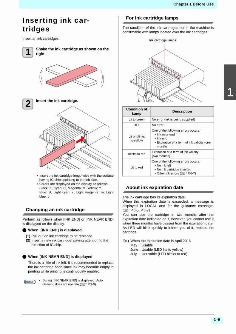
Inserting ink car-tridgesInsert an ink cartridges.
1 Shake the ink cartridge as shown on the right.
2 Insert the ink cartridge.
• Insert the ink cartridge lengthwise with the surfacehaving IC chips pointing to the left side.
• Colors are displayed on the display as follows.Black: K, Cyan: C, Magenta: M, Yellow: Y, Blue: B, Light cyan: c, Light magenta: m, Lightblue: b
Changing an ink cartridge
Perform as follows when [INK END] or [INK NEAR END]is displayed on the display.
When [INK END] is displayed
(1) Pull out an ink cartridge to be replaced.(2) Insert a new ink cartridge, paying attention to the
direction of IC chip.
When [INK NEAR END] is displayed
There is a little of ink left. It is recommended to replacethe ink cartridge soon since ink may become empty inprinting while printing is continuously enabled.
For Ink cartridge lamps
The condition of the ink cartridges set in the machine isconfirmable with lamps located over the ink cartridges.
About ink expiration date
The ink cartridge has its expiration date.When this expiration date is exceeded, a message isdisplayed in LOCAL and for the guidance message.( P.6-5, P.6-7)You can use the cartridge in two months after theexpiration date indicated on it, however, you cannot use itwhen three months have passed from the expiration date.As LED will blink quickly to inform you of it, replace thecartridge
Ex.) When the expiration date is April 2016May : UsableJune : Usable (LED lits to yellow)July : Unusable (LED blinks to red)
• During [INK NEAR END] is displayed, Auto cleaning does not operate.( P.3-9)
Condition of Lamp
Description
Lit to green No error (ink is being supplied)
OFF No error
Lit or blinks to yellow
One of the following errors occurs.• Ink near-end• Ink end• Expiration of a term of ink validity (one
month)
Blinks to redExpiration of a term of ink validity (two months)
Lit to red
One of the following errors occurs.• No ink left• No ink cartridge inserted• Other ink errors ( P.6-7)
Ink cartridge lamps

Chapter 1 Before Use
1-10
Caution in handling of ink cartridges MediaUsable media sizes and notes for handling are described.
Usable sizes of media
Caution in handling of medias
Pay attention to the followings for handling of medias.
• Use genuine ink cartridges for this machine. This machine functions by recognizing the genuine ink cartridges. In case of troubles caused by modified ink cartridges or the like, it shall be out of the warranty even within the warranty period.
• If the ink cartridge is moved from a cold place to a warm place, leave it in the room temperature for three hours or more before using it.
• Be sure to thoroughly consume the ink in the ink cartridge, once it is opened, within three months. If an extended period of time has passed away after opening the cartridge tank, printing quality would be poor.
• Make sure to store ink cartridges in a cool and dark place.
• Store ink cartridges and waste ink tank in a place that is out of the reach of children.
• Request an industrial waste processor for processing of empty ink cartridges.
• Do not shake ink cartridges violently. This may result in ink leakage from the ink cartridges.
• Never refill the ink cartridges with ink. This may result in troubles.MIMAKI will not bear any responsibility for any damage caused by the use of the ink cartridges refilled with ink.
• Do not touch or stain the contacts of the ink cartridge. This may cause damages on printed circuit boards.
• Do not disassemble the ink cartridges.
Model CJV300-130 CJV300-160
Type of Recommended media
Label stock (paper-based) / PVC sheet (including laminated; thickness no more than 0.25 mm) / Reflective sheet (excluding high-luminance reflective sheet) / Heat transfer rubber sheet
Maximum width 1371mm 1620mm
Minimum width 210mm 210mm
Maximum printing width
1361mm 1610mm *1
*1. When the MARGIN(RIGHT/LEFT) setting has been set to theminimum (-10 mm).
Rol
l med
ia
Thickness 1.0mm or less
Roll outside diameter
Paper media : Φ250mm or lessOther media : Φ210mm or less
Roll weight 40kg or less
Roll inside diameter
3 or 2 inches
Side printed Side facing outward
Roll end treatment
The roll end is gently fixed to the core with weak-adhesive tape or weak glue for easy removal.
• Use media recommended by MIMAKI to ensure reliable, high-quality printing.Set the heater temperature to meet the characteristics of the media.
• Pay attention to the expansion and contraction of the media.Do not use media immediately after unpacking. The media can be affected by the room temperature and humidity, and thus it may expand and contract.The media have to be left in the atmosphere in which they are to be used for 30 minutes or more after unpacked.
• Do not use curled media.This may result in paper jamming.If a regular-sized coated sheet of media is rolled and stored, the coated side has to face outside.
• Be careful to dusts on the edge face of the media.Some rolls have dusts contained in the package gathered on the edge surface of the roll. If you use as it is, the drawing quality may be degraded due to nozzle missing or ink drops. Be sure to set the roll after removing dusts adhering on the edge face of the roll.

1-11
Chapter 1 Before Use
1
2
2
2
2
Menu modeThis machine has 4 modes. Each menu mode is described below.
NOT-READY mode
This is the mode in which the media has not been detected yet.
LOCAL mode
Local mode is the mode for the drawing preparation state.All the keys are effective.The machine can receive data from the computer.However, it does not perform printing.
This mode permits the following operations:
• Pressing the JOG keys to set up a drawing origin and drawing area.
• Pressing the [ENTER] key to check the remaining amount of ink, the description of the cartridge error, themodel name, the firmware version, and so on.
MENU mode
To set MENU mode, press the [FUNC1] key when this machine is in LOCAL mode.In this mode, each function can be set.
REMOTE mode
This machine prints the data it receives.
Displays the current heater temperature.The color of the icon above the temperature display changes with the current heater status.
Orange : Temperature risingGreen : Set temperature
reachedGlay : Heater off
Displays the detected media width.
Displays detected ink levels (approximate)
Displays the functions thathave been set for the function
keys [FUNC1] – [FUNC3].
[SEL] key Function key [FUNC1] ~ [FUNC3]Press the [SEL] key to change the functions.
Screen display in Local mode

1-12
Chapter 1 Before Use

This chapter
describes procedures and setting methods for ink and media preparation, and printing.
Workflow of printing ......................................2-2Turning the Power ON/OFF ..........................2-3
Turning the Power ON ................................ 2-3Turning the Power OFF ............................... 2-3
Setting a Media .............................................2-4Adjusting the Head Height .......................... 2-4Adjusting the Position of the Pinch Roller According to the State of a Media ............... 2-5Maximum Print Area/Cut Area .................... 2-8Notes When Using media Holder ................ 2-8Setting a roll media ..................................... 2-9Setting the pinch roller pressure ............... 2-11Take-up device .......................................... 2-12Setting leaf media ..................................... 2-13Changing the printing origin ...................... 2-14
Preparing for the Heaters ............................2-14Changing the Temperature Settings for the Heaters ...................................................... 2-14
Test Printing ................................................2-15Test Printing .............................................. 2-15Perform test printing with the normal test pattern ....................................................... 2-16Perform test printing with the test pattern for checking white ink ................................ 2-16
Head Cleaning ............................................2-17About head cleaning ................................. 2-17Perform head cleaning depending on the test printing result ...................................... 2-17
Setting of Media Correction .........................2-17Setting of Media Correction ......................2-17
If the Positions of Dots Shift... .....................2-18Printing Data ...............................................2-18
Starting a Printing Operation .....................2-18Stopping a Printing Operation ....................2-19Deleting Received Data (Data Clear) ........2-19
Cutting a media ...........................................2-19Workflow of cutting ......................................2-20Installing Tools ............................................2-21
When a Cutter Is Used ..............................2-21How to Install a Ballpoint Pen ....................2-22
Setting the cutting conditions ......................2-24About the Cut Conditions ...........................2-24Select the tool condition .............................2-24Set the Cut Conditions ...............................2-25
Test Cutting .................................................2-26Cutting Data ................................................2-26
Setting the origin ........................................2-26Start cutting ................................................2-26Stopping a Cutting Operation (Data Clear) ...............................................2-27Removing the Cutter Unit Temporarily ......2-27
Cutting a media ...........................................2-27
Chapter 2
Basic Operations

2-2
Chapter 2 Basic Operation
Workflow of printing
Turning the Power ON/OFF Referring to “Turning the Power ON/OFF” ( P.2-3).
Setting a Media Referring to “Setting a Media” ( P.2-4).
Preparing for the Heaters Referring to “Preparing for the Heaters” ( P.2-14).
Test Printing Referring to “Test Printing” ( P.2-15).
Head Cleaning Referring to “Head Cleaning” ( P.2-17).
Printing Data Referring to “Printing Data” ( P.2-18)

2-3
2
2
2
2
2
Chapter 2 Basic Operation
Turning the Power ON/OFFTurning the Power ON
This machine is provided with the following two powerswitches:Main power switch :
It is located on the side of this machine.Keep this switchON all the time.
[END/POWER] key :Normally, use this key to turn the power ON/OFF.The nozzle clogging prevention function periodicallyoperates even with the [END/POWER] key turned OFFwhen the main power switch is turned ON.
1 Turn the main power switch ON.
• Set the main power switch located on the side ofthis machine to the “I” side.
• The firmware version is displayed when the poweris turned ON, and the machine performs its initialoperation.
2 Turn the power on, by pressing the key.
• The machine enters LOCAL.
3 Turn ON the power of the connected PC.
Turning the Power OFF
When having ended the operation of the machine, turn thepower OFF by pressing the power switch located on thefront side.Check the following items when turning the power OFF.
• If the machine is receiving data from the PC or if thereis any data that has not been output yet
• If the head has returned to the capping station• If any error has occurred
( P.6-7 “Ink Error”)
1 Turn OFF the power of the connected PC.
2 Turn the power off, by giving the key a long press.
• Do not turn OFF the main power switch locatedon the side of the machine.
• To use this machine again, press the [END/POWER] key .
Cautions about Turning the Power OFF
Do not turn the main power switch OFF.
When the main power switch is ON, the powerperiodically turns ON and the nozzle cloggingprevention function (flushing function) operates.When the main power switch has been turned OFF,the auto maintenance functions, such as flushing, donot operate, and this may cause nozzle clogging.
Turn the power OFF after having checked theposition of the head.
If the power is turned OFF in a state where the headhas not returned to the capping station, the ink headdries, which may cause nozzle clogging.In this case, turn the power ON again and check thatthe head has returned to the capping station, and turnthe power OFF.
Do not turn the power OFF during printing or cutting.
The head may not return to the capping station.
After having turned the power switch OFF by pressing [END/POWER] key, turn the main power switch OFF.
When turning the main power switch off for moving themachine or for solving the error or the like, press the[END/POWER] key a long time on the front of themachine, check the display is turned off on theoperation panel, and turn the main power switch off.
• Turn the power ON after the front cover and maintenance cover are closed.
• The head nozzle may result in nozzle clogging if the main power switch is left OFF for a long time.
Main power switch
[END/POWER] key
[END/POWER] key

2-4
Chapter 2 Basic Operation
Setting a MediaThis machine can be used with a roll media and leafmedia.For usable medias, refer to P.1-10 “Usable sizes ofmedia”.
Adjusting the Head Height
Adjust the head height according to the thickness of themedia you use.
1 Move the carriage to the platen.
• When the device is turned ON:Execute [ST.MAINTENANCE - CARRIAGE OUT]of the Maintenance functions.( P.5-6 Step1,2)
• When the device is turned off :Open the front cover, then move the carriage byhand.
2 Loosen the screw in front.
• Loosen the screws, rotating each by one turn of astandard screwdriver.
3 Adjust the height-adjusting lever according to the media.
• Adjust the position of the lever, referring to P.2-4“For the Adjusting Lever and the Range”.
• Set the height-adjusting lever to the highest stageor the lowest stage.Setting it to the intermediateheight, a printing fault can result.
4 Fix the carriage.
• Fasten the screw securely.
5 Return the carriage to the station position.
For the Adjusting Lever and the Range
• Take care not to drop the media on your foot when setting the media.It may cause an injury due to the media.
• When setting a roll media, work by two or more people. Otherwise, you may hurt your back by the weight of the roll media.
• Adjust the head height prior to setting the media.If the head height is adjusted after the media is set, this may cause a media jamming, deterioration of the print quality or head damage.
• The range of the initial head height is adjustable by 2 levels according to the purpose of use.
• The range of the printing height of this machine is from L range (2 mm/3 mm) to H range (3 mm/4 mm). (Set to L range 2 mm at shipping)
Carriage
• If you set the height-adjusting lever to the H range or L range, do not push the lever upward or downward when you tighten the screw.
Range Head height Note
L range 2mm
(The set position at shipping)You can raise the base of the head height 1 to 2 mm higher.To do this, contact one of our sales representatives.
M range 2.5mm
H range 3mm
Height-adjusting lever
2-5
2
2
2
2
2
Chapter 2 Basic Operation
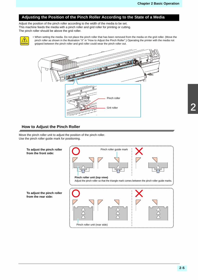
Adjusting the Position of the Pinch Roller According to the State of a Media
Adjust the position of the pinch roller according to the width of the media to be set.This machine feeds the media with a pinch roller and grid roller for printing or cutting.The pinch roller should be above the grid roller.
How to Adjust the Pinch Roller
Move the pinch roller unit to adjust the position of the pinch roller.Use the pinch roller guide mark for positioning.
• When setting the media. Do not place the pinch roller that has been removed from the media on the grid roller. (Move the pinch roller as shown in the illustration “X” in “How to Adjust the Pinch Roller”.) Operating the printer with the media not gripped between the pinch roller and grid roller could wear the pinch roller out.
Pinch roller
Grit roller
Pinch roller guide markTo adjust the pinch roller from the front side:
To adjust the pinch roller from the rear side:
Pinch roller unit (top view)Adjust the pinch roller so that the triangle mark comes between the pinch roller guide marks.
Pinch roller unit (rear side)
2-6
Chapter 2 Basic Operation
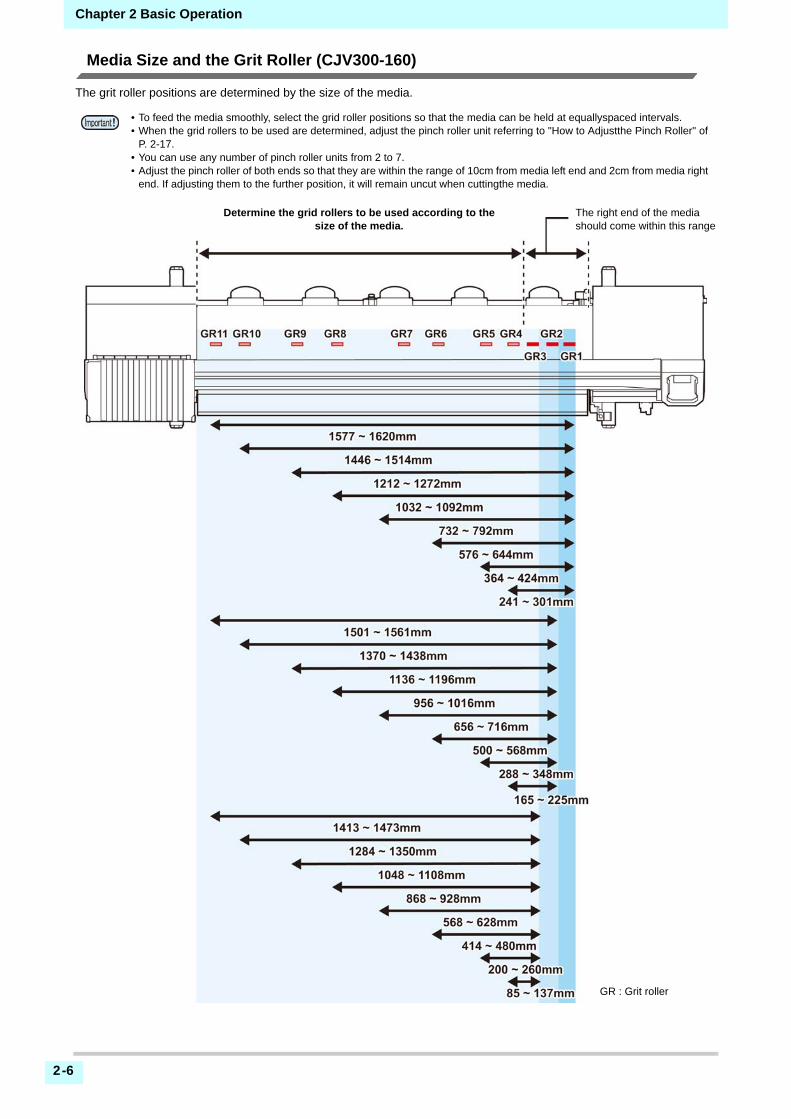
Media Size and the Grit Roller (CJV300-160)
The grit roller positions are determined by the size of the media.
• To feed the media smoothly, select the grid roller positions so that the media can be held at equallyspaced intervals.• When the grid rollers to be used are determined, adjust the pinch roller unit referring to "How to Adjustthe Pinch Roller" of
P. 2-17.• You can use any number of pinch roller units from 2 to 7.• Adjust the pinch roller of both ends so that they are within the range of 10cm from media left end and 2cm from media right
end. If adjusting them to the further position, it will remain uncut when cuttingthe media.
Determine the grid rollers to be used according to the size of the media.
The right end of the media should come within this range
GR : Grit roller

2-7
2
2
2
2
2
Chapter 2 Basic Operation
Media Size and the Grit Roller (CJV300-130)
The grit roller positions are determined by the size of the media.
• To feed the media smoothly, select the grid roller positions so that the media can be held at equallyspaced intervals.• When the grid rollers to be used are determined, adjust the pinch roller unit referring to "How to Adjustthe Pinch Roller" of
P. 2-17.• You can use any number of pinch roller units from 2 to 6.• Adjust the pinch roller of both ends so that they are within the range of 10cm from media left end and 2cm from media right
end. If adjusting them to the further position, it will remain uncut when cuttingthe media.
Determine the grid rollers to be used according to the size of the media.
The right end of the media should come within this range.
GR : Grit roller

2-8
Chapter 2 Basic Operation
Maximum Print Area/Cut Area
The maximum printed area/cut area varies, depending on the position of the pinch roller( P.2-8 to P.2-7) and the originposition ( P.2-14). The white area shown in the following figure represents the maximum print/ cut area.The area other than that is the dead space that cannot be printed/cut.
Notes When Using media Holder
Setting Position of the Media
Set the media so that the right end of the media will be inside the area shown below.
The End of the Media Should Not Exceed the Slit Line on the Platen
CJV300-130 CJV300-160
Maximum printing/cut width 1361mm 1610mm
Set the media so that the right end of the media will be inside the area shown by an arrow. (up to the 3rd grid roller from the right end in front of the main body)
Media
Media press
Slit line
2-9
2
2
2
2
2
Chapter 2 Basic Operation
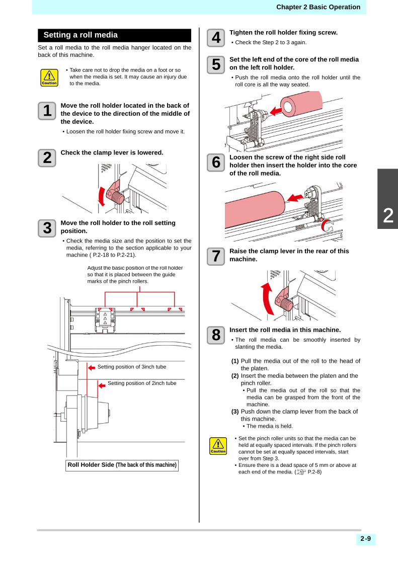
Setting a roll media
Set a roll media to the roll media hanger located on theback of this machine.
1 Move the roll holder located in the back of the device to the direction of the middle of the device.
• Loosen the roll holder fixing screw and move it.
2 Check the clamp lever is lowered.
3 Move the roll holder to the roll setting position.
• Check the media size and the position to set themedia, referring to the section applicable to yourmachine ( P.2-18 to P.2-21).
4 Tighten the roll holder fixing screw.
• Check the Step 2 to 3 again.
5 Set the left end of the core of the roll media on the left roll holder.
• Push the roll media onto the roll holder until theroll core is all the way seated.
6 Loosen the screw of the right side roll holder then insert the holder into the core of the roll media.
7 Raise the clamp lever in the rear of this machine.
8 Insert the roll media in this machine.
• The roll media can be smoothly inserted byslanting the media.
(1) Pull the media out of the roll to the head ofthe platen.
(2) Insert the media between the platen and the pinch roller.• Pull the media out of the roll so that the
media can be grasped from the front of themachine.
(3) Push down the clamp lever from the back of this machine.• The media is held.
• Take care not to drop the media on a foot or so when the media is set. It may cause an injury due to the media.
Roll Holder Side (The back of this machine)
Setting position of 2inch tube
Setting position of 3inch tube
Adjust the basic position of the roll holder so that it is placed between the guide marks of the pinch rollers.
• Set the pinch roller units so that the media can be held at equally spaced intervals. If the pinch rollers cannot be set at equally spaced intervals, start over from Step 3.
• Ensure there is a dead space of 5 mm or above at each end of the media. ( P.2-8)

2-10
Chapter 2 Basic Operation
9 Pull out the roll media out.
(1) Open the front cover.(2) Raise the clamp lever from the front of this
machine.(3) Pull out the roll media gently and stop pulling
when locked lightly.
10 Make the roll media even then lower the clamp lever.
• Pulling several positions of the media lightly,Lower the clamp lever after confirming that theamount of the roll media pulled out is almosteven.
11 Hold the media with the media press gently.
• Set the media so that no media sticks out from theright end pinch roller to the right side.
• When using a thick media, remove the mediapress from the media before printing.
12 Set an empty core of the roll media on the take-up device.
13 Press the key to select “ROLL” .
• Detects the media width.• When [MEDIA DETECT] of the machine setup is
“MANUAL” ( P.3-13), refer to P.2-11 "Settingof the manual media width setting" and enter themedia width.
14 When the media width detection is complete, use to enter the number of the pinch rollers you are using.
• When the pinch roller number in "MEDIADETECT" of the machine setup is set to OFF( P.3-13), the screen to enter the number ofpinch rollers is not displayed. Proceed to step 16.
15 Press the key.
• When [MEDIA RESIDUAL] of the machine setupis “ON” ( P.3-13), the screen for enteringmedia remaining amount is displayed afterpressing [ENTER] key.( P.2-11)
Media press
• When installing the media, align the media’s right edge with the slit line in the platen. Placing the media rightward of the slit line will make it rise up if it moves obliquely, and this could cause damage to the head.
• If a media is misaligned to the right/left more than fixed position, a error message “MEDIA SET POSITION R” is displayed. Set the media again.
Media
MediaPress
Slit Line
Core
Take-up device

2-11
2
2
2
2
2
Chapter 2 Basic Operation
16 Secure the media on the take-up device. ( P.2-12)
(1) Feed the media up to the core of the roll media ofthe take-up device by pressing the [] key.
(2) Fix the middle of the media with adhesive tape.(3) In the same manner, fix the left side and right side
of the media.• Make sure that the there is no slack or wrinkle on the
media in such condition that the roll media is pulledto right and left evenly, and stick the tape.
Setting the pinch roller pressure
After setting the media in place, set the pressure of the pinchrollers that retain the media.Be sure to set a pressure value that is appropriate for the media.With an inappropriate pinch roller pressure value, the mediacould skew during printing or cutting, or the pinch rollers couldremain on the media after pinching.You can set the following items in pinch roller pressure settings:
1 Press the (PR) key in LOCAL.
2 Press to select setting item, and press the key.
3 Press , to select the setting value.
4 Press the key.
5 Press , to end the setting.
• If you want to switch to another settingimmediately, press [<].
Entering the media remaining amount
When [MEDIA RESIDUAL] of the machine setup is “ON”( P.3-13), the screen for entering media remainingamount is displayed after detecting the media width.
1 Display the screen for entering media remaining amount.
2 Press to enter the media remaining amount.
3 Press the key.
Setting of the manual media widthsetting
When [MEDIA DETECT] of the machine setup is“MANUAL” ( P.3-13), set the media width in thefollowing method.
1 Display the screen for entering the right edge position of the media.
2 Press to enter the right edge position of the media.
3 Press the key.
• Next, the screen to enter the left edge position ofthe media is displayed.
4 Press to enter the media the left edge position of the media.
5 Press the key.
Item Setting value Outline
NUMBER FOR USE 1 ~ 7
Set the number of the pinch rollers you are using.This number differs depending on the model you are using.
PRINTLOW/ MID/
HIGHSet the pinch roller pressure for printing.
CUT: ENDSLOW/ MID/
HIGH
Set the pressure of the edge pinch rollers (left and right edges) used when cutting the media.
CUT: INNEROFF/ LOW/ MID/ HIGH
Set the pressure of the pinch rollers except for the edge pinch rollers used when cutting the media.
CHANGE EXECUTION
PRINT/ CUTSwitch between the setting for printing and cutting.
• Be careful not to set the position beyond the media range, as it may cause printing or cutting outside the media.

2-12
Chapter 2 Basic Operation
About the media residual print
When [MEDIA RESIDUAL] of the maintenance function is“ON” ( P.3-13), You can print a list of print the currentdate and media remaining.
1 In Local, Press .
• It enters into the origin setting mode.
2 Press the key.
• Appear the confirmation screen of mediaremaining print.
3 Press the key.
• Media residual print starts.
Take-up device
With the switch of the narrow take-up device, select thetake-up direction of the media or others.
Setting the torque limiter
The take-up device is provided with a torque limiter.The take-up torque can be adjusted with the torque limiter. (The torque limiter is set to "media" at delivery.)If the tension is too strong to use a thin media of media,lower the take-up torque with the torque limiter.Clockwise turn :
Increases torque (a heavy and thicker media such astarpaulin or the like)
Counterclockwise turn :Decreases torque (For light media)
When Not Using Taking-up Device
Direction selector switch
UP (REVERSE)
The take-up device winds the media with the printed side facing in.
DOWN (FORWARD)
The take-up device winds the media with the printed side facing out.
ON/OFF button
Turns the winding motion on/off.(When you press the button and operate the take-up device, the device keeps taking up the media until you press the button again. *1)
*1. You can also change the setting so that the taking-up operation onlylasts while the ON/OFF button is being pressed. For details, refer to“Setting Top Blower” ( P.3-12) in machine settings.
ON/ OFF buttonDirection selector switch
• When performing printing or cutting of 700 mm or more without using the taking-up device, evacuate the takingup device to right and left. The quality of the print and cut may become low because of the impact when the front end of the media touches the taking-up device.
50% of the maximum 100% of the maximum
Scale of the torque
Adjustment nut

2-13
2
2
2
2
2
Chapter 2 Basic Operation
Setting leaf media
Unlike roll media, leaf media does not need to be retainedwith the roll holders.
1 Raise the clamp lever.
2 Insert the leaf media between the platen and the pinch rollers.
• Set the media so that no media sticks out from theright end pinch roller to the right side.
3 To print, hold the media with the media press gently.
• Set the media so that no media sticks out from theright end pinch roller to the right side.
• When using a thick media, remove the mediapress from the media before printing.
4 Push down the clamp lever.
• Set the media straight.
5 Press the key.
6 Press the key to select "LEAF" .
7 The media detection is started.
(1) The media width is detected.(2) The media is fed then the rear end of media
is detected.(3) It returns to the Local when the detection is
completed.
• Set the pinch roller so that the media is held at equally spaced intervals. If the pinch rollers cannot be set at equally spaced intervals, start over from Step 2.
• Ensure there is a dead space of 5 mm or above at each end of the media. P.2-8).
Clamp lever
Pinch roller
Media press
• Set the media on the black part of the platen so that it comes out approximately 40mm. If it is shorter than that, it may not be able to perform the media detection.
• After setting the media in place, set the pinch roller pressure, referring to P.2-11 “Setting the pinch roller pressure”.
Media
Approximately 40mm

2-14
Chapter 2 Basic Operation
Notes when using media press
Changing the printing origin
The position of the printing origin can be changed.Moving the LED pointer to the changing position anddeciding the position.
1 In Local, Press .
• It enters into the origin setting mode.
2 Set a light point of the LED pointer to the changing position by pressing
.
• Select the carriage and media, moving the pointwith [][][][].
3 After determining the origin, press the key.
• The printing origin is changed.
Typical setting position of printing origin
The printing origin in the depth direction (X') is positionedat about 75 mm rearward from the slot for cutting on theplaten. The printing origin in the scanning direction (Y') ispositioned at 15 mm from the right end of the media. Thevalue in the scanning direction (Y') can be changed using[MARGIN] in FUNCTION mode. ( P.3-8) This can be changed by using the Jog key.
Preparing for the HeatersChanging the Temperature Settingsfor the Heaters
You can change/save the temperature settings for theheaters with “Heater” of the setting mode. ( P.3-6)Here, changing method of the temperature set in thesetting mode is explained.Set the heater temperature according to thecharacteristics of the media you use.The temperature of the heaters has been set to "OFF" asdefault.Appropriate temperature adjustment can be madebecause the temperature can be adjusted even duringprinting.It may take several minutes to tens of minutes for the settemperature to be reached, depending on the ambienttemperature.
1 Press the key,and press the (Heater) in LOCAL.
• The heater temperature adjustment screen will bedisplayed.
2 Press to set the temperature of each heater.
Heater selecting: Select with [][]Temperature setting: Set with [][]
• The heater starts to get hot.
3 The heating of the heater stops.
• When the heater temperature reaches the settemperature, the heater icon lights in green.
4 Press the key to stop heating.
• The screen returns to LOCAL.
• When installing the media, align the media’s right edge with the slit line in the platen. Placing the media rightward of the slit line will make it rise up if it moves obliquely, and this could cause damage to the head.
• If a media is misaligned to the right/left more than fixed position, a error message “MEDIA SET POSITION R” or is displayed. Set the media again.
Media
MediaPress
Slit Line
slot for cutting
approx. 75 mm(X’)
15 mm (Y’)

2-15
2
2
2
2
2
Chapter 2 Basic Operation
Test PrintingPrint a test pattern to check that there are no dischargingdefects such as nozzle clogging (slight touching of ink ornozzle missing).
Relationship between head row and test pattern
The relations between head row and test pattern printposition are as follow.
About test patterns
This machine provides you two test patterns.
Normal test pattern (when using ink other than white ink)
When you use ink that you can check by printing a testpattern on a white media, print this test pattern.
Test pattern for checking white ink
When you use a white media and wish to checkdischarging status of white ink, print this test pattern.
Note on test printing
Test Printing
Print a test pattern to check that there are no dischargingdefects such as nozzle clogging (slight touching of ink ornozzle missing).In addition, you can select the orientation of the testpattern to print from two types in order to perform testprinting repeatedly. Select one depending on your use.
• When using leaf media, set a media of more than A3 size put horizontally. If a media with narrow width is set, printing will only be conducted to midway.
• When using a roll media, rewind the media by hand before printing so that it is not loose. When the roll media has not been rewound tightly, it may cause image quality to deteriorate.
Med
ia a
dvan
ce d
irect
ion
Pattern of head 1
Pattern of head 2
Head 2
Head 1
Check before test printing.
• If a media has been set P.2-4
• If the origin position has been set
• If the head gap has been adjusted P.2-4
Media-feeding direction
: When the set value is "FEED DIR."
: When the set value is "SCAN DIR."

2-16
Chapter 2 Basic Operation
Perform test printing with the normaltest pattern
1 Press the (TEST PRINT/CLEANING),and press the key in LOCAL.
• TEST PRINT MENU will be displayed.• Press [][] to change the test pattern
orientation.The orientation selected here will bereflected on when you will print next time.
• When performing test printing after havingchanged the orientation from "SCAN DIR." to"FEED DIR.", the line is fed to the position of thefirst test printing.
2 Press the key.
• Test printing starts.• When the printing has been completed, the
screen returns to LOCAL.
3 Check the printed test pattern.
• When the result is normal, end the operation.• When the result is abnormal, perform head
cleaning.( P.2-17)
Perform test printing with the testpattern for checking white ink
It makes easier to check if print the background to thewhite ink locations in the pattern.
1 Press the (TEST PRINT/CLEANING),and press the key in LOCAL.
• TEST PRINT MENU will be displayed.
2 Press to select “SpotColor Check”.
3 Press the key.
• Print a test pattern in the following orders.
(1) Print the pattern daubed with black.(2) Dry the pattern for thirty seconds.
• When press the [ENTER] key, cancel waitingtime and shift to step (3).
(3) Return the media automatically and print the test pattern.
4 Check the printed test pattern.
• When the result is normal, end the operation.• When the result is abnormal, perform head
cleaning.( P.2-17)
Abnormal pattern
Clogged with ink
Normal pattern
Nozzles are dirty
Abnormal pattern
Clogged with ink
Normal pattern
Nozzles are dirty

2-17
2
2
2
2
2
Chapter 2 Basic Operation
Head CleaningAbout head cleaning
Check the printed test pattern result and perform cleaningdepending on the status.Select one from the four types below:
NORMAL : When any line is missingSOFT : When only head wiping is needed (when
lines are bent)HARD : When poor image quality cannot be
improved even by NORMAL or SOFTcleaning
ULTRA : When poor image quality cannot beimproved even by HARD cleaning
Perform head cleaning depending onthe test printing result
There are four types of head cleaning. Use one bychecking the test pattern.
1 Press the (TEST PRINT/CLEANING) key in LOCAL.
• CLEANING MENU will be displayed.
2 Press to select the cleaning type.
• NORMAL : Select this if any line is missing.• SOFT : When only head wiping is desirable.
(in case of bent lines)• HARD : Select this if inferior printing cannot
be improved even by [NORMAL] or[SOFT] cleaning.
• ULTRA : Select this if inferior printing cannotbe improved even by [HARD]cleaning.
3 Press the key.
4 Press to select the cleaning head, and then press the ().
• After selecting the head, press the [FUNC2] keyand put a check in the check box. The head whose box has been checked will becleaned.
• To have both head 1 and head 2 cleaned, put acheck in both their check boxes.
5 Press the key.
6 Perform test printing again, and check the result.
• Repeat the cleaning and the test printing until theprinting result becomes in normal.
Setting of Media CorrectionCorrect the media feed amount to match the type ofmedia you are using.If the correction value is not appropriate, stripes mayappear on the printed image, thus resulting in a poorprinting.
Setting of Media Correction
A pattern for media correction is printed and a media-feeding rate is corrected.
1 Set a media. ( P.2-4)
2 Press the key, and press the (ADJUST) in LOCAL.
• ADJUST MENU will be displayed.
3 Press the key twice to print the
correction pattern
4 Check the correction pattern and enter a correction value.
• A screen for entering the correction value will bedisplayed.
• Enter a correction value in "+":The boundary between the two bands is widened.
• Enter a correction value in "-":The boundary between the two bands isnarrowed.
• When you change the correction value by "30",the width of the boundary changes by about 0.1mm.
When the image quality is not improved after the head cleaning.• Clean the wiper and ink cap. ( P.5-6)• Wash the head nozzle. ( P.5-7)
• On completion of [MEDIA COMP.] during use of a roll media, the media returns to the printing origin. Then the roll media in the rear of this machine will slacken.Before printing, take up the slack in the roll media by hand; a loose roll media can result in an inferior image quality.
• When printing with a take-up device, set the media first and perform media correction.
• Two bands are printed in the correction pattern.• Make adjustment so that an even color density is
obtained in the boundary between the two bands.
Second band
First band
Med
ia a
dvan
ce d
irect
ion

2-18
Chapter 2 Basic Operation
If the Positions of Dots Shift...When the condition for printing (media thickness/ink type/etc.) has been changed, perform the following operationto correct the ink drop position for bidirectional (Bi)printing and obtain the proper printing result.
Example of a Printed Pattern
1 Press the key, and press the (ADJUST) in LOCAL.
• ADJUST MENU will be displayed.
2 Press , and press the key.
• “DROP.POScorrect” will be selected.
3 Press the key.
• Printing of the Drop position correct printed pattern will start.
• Multiple test patterns are printed. (The printedpatterns are called Pattern 1, Pattern 2, Pattern3... in the order of printing.)
4 Press to enter a correction value of Pattern 1, and press the key.
• Corrected feeding rate: -40 to 40• Check the test patterns. The position where an
outward feeding line and a return feeding linebecome one straight line is the correction value.
• When the correction value in not between -40 and40, adjust the height of the printing heads andperform the operations in Step 2 and later.
5 In the same way as in Step 4, enter a correction value of Pattern 2 and later, and press the key.
6 Press the key several times to end the setting.
Printing DataStarting a Printing Operation
1 Setting a Media ( P.2-4)
2 Press the (REMOTE) key in LOCAL.
• The screen changes to REMOTE, and data canbe received from the PC.
3 Transmit data to be printed from the PC.
• For the method of data transmission, see theinstruction manual for the output software.
4 Start printing.
• The printing speed may change, depending onthe width of the set media or the position of theprint origin even when the same data is printed.This is because of a difference in resolution.
• When using leaf media, set a media of more than A3 size put horizontally. If a media with narrow width is set, printing will only be conducted to midway.
The dots at the fourth position counted from the zero position in the positive direction form a straight line.In this case, the dot position correction value is 4.0.
Output direction
• When using a roll media, rewind the media by hand before printing so that it is not loose.When the roll media has not been rewound tightly, it may cause the image quality to deteriorate.
Resolution360 /540 /720 /1440 DPI
Number of passes
The length of media printed
Scan directionUni:UnidirectionalBi . :Bidirectional
Scanning speedStd:Standard speedHi :Double speed
Data typeVd : Variable dataNd : Normal data

2-19
2
2
2
2
2
Chapter 2 Basic Operation
Stopping a Printing Operation
Perform the following operation when stopping a printingoperation halfway.
1 Press the (LOCAL) during printing.
• The printing operation stops.• Interrupt data sending at the PC side during the
data is sent from the PC.• Printing restarts from the interrupted data by
repressing the [REMOTE] key.
Deleting Received Data (Data Clear)
When you want to stop printing, delete the alreadyreceived data.
1 Press the key, and press the (DATA CLEAR) in LOCAL.
2 Press the key.
• The received data is erased then it returns to theLocal.
Cutting a mediaBy using the keys on the operation panel, you can cut themedia at any position.
1 In Local, Press .
• It enters into the origin setting mode.• By pressing [] , feed the media to the cutting
position.
2 Press the key.
• The media is cut.• When the cutting has been completed, the current
mode returns to LOCAL.
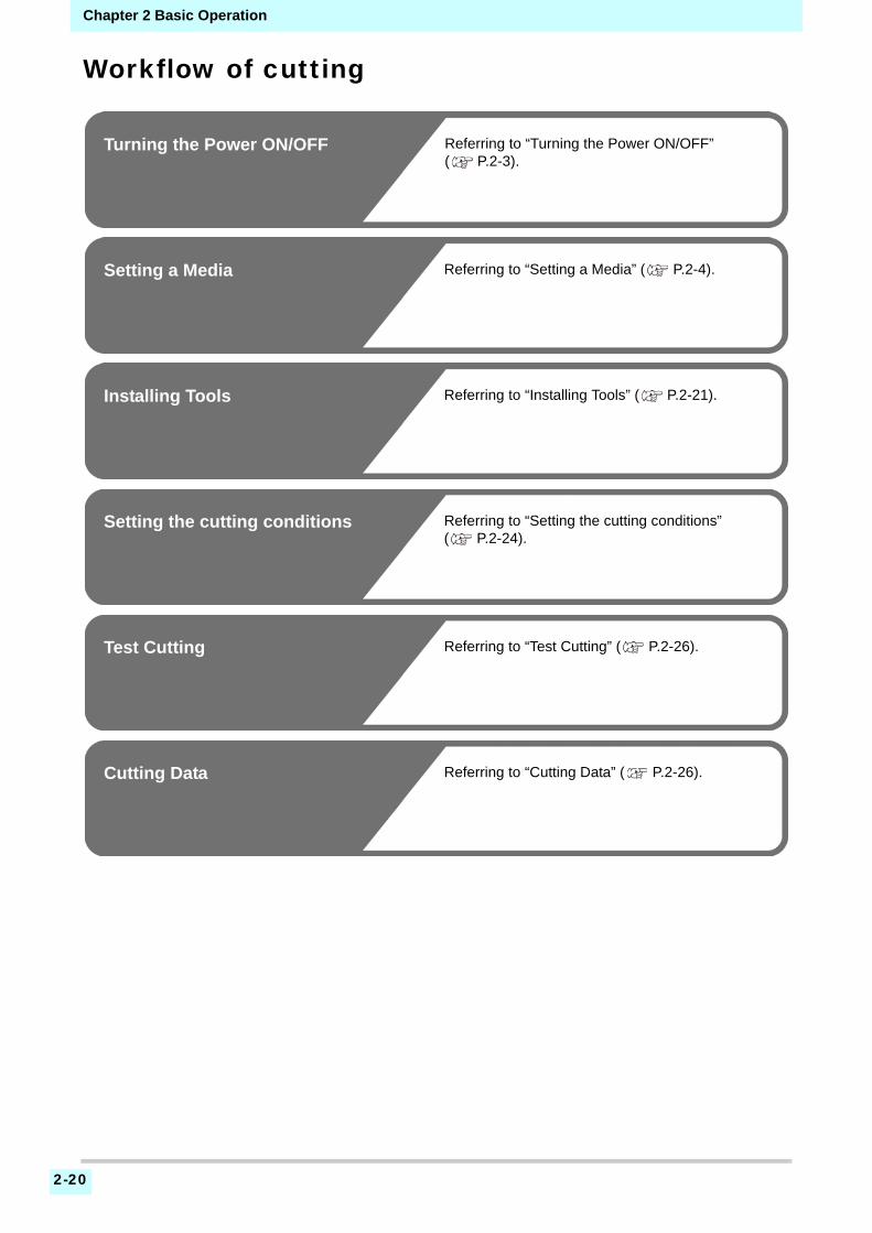
2-20
Chapter 2 Basic Operation
Workflow of cutting
Turning the Power ON/OFF Referring to “Turning the Power ON/OFF” ( P.2-3).
Setting a Media Referring to “Setting a Media” ( P.2-4).
Installing Tools Referring to “Installing Tools” ( P.2-21).
Setting the cutting conditions Referring to “Setting the cutting conditions” ( P.2-24).
Test Cutting Referring to “Test Cutting” ( P.2-26).
Cutting Data Referring to “Cutting Data” ( P.2-26).

2-21
2
2
2
2
2
Chapter 2 Basic Operation
Installing ToolsThis machine allows you to use the following tools:Cutter :
This tool is selected when an image printed on a mediais cut or when letters are cut with a cutting media.
Pen (water-based ballpoint pen) : This tool is used to perform “test printing” for checkinghow images or letters are cut actually.
When a Cutter Is Used
How to install a cutter
1 Remove the cap located at the edge by rotating it, and replace the cutter with a new one using tweezers or the like.
2 Turn the adjusting knob to adjust the protruding amount of the cutter.
• arrow to protrude the cutter blade. ( 0.5 mm per revolution)
Adjusting the protrusion of the cutter blade
Adjust the cutter blade according to the types of the cutters andthe sheet for use.After adjusting the protrusion of the cutter blade, set the cuttingconditions and conduct test cutting to check the cutting quality.For the cutter supplied with unit, the protruding amount of theblade can be adjusted with the cuttermounted in the pencarriage.
1 Turn the adjusting knob to adjust the protruding amount of the cutter blade.
• arrow to protrude the cutter blade.( 0.5 mm per revolution)
Protruding amount of the cutter blade
• Do not touch the cutter with your fingers.The sharp blade edge of the cutter may cause you to get injured.
• Do not shake the tool after having set the cutter.Otherwise, the blade edge may pop out, causing you to get injured.
• Store the cutter blade in a place that is out of the reach of children. In addition, dispose of used cutter blades according to regional laws and regulations.
Cutter holder
Cutter
Cap
Cutter
Adjusting knob
• Take care not to protrude the blade too much. If the cutter is used with its blade excessively protruded, the cutter can cut out the base paper, thus damaging the main unit.
• See the appendix for the blade adjustment of the cutters other than the auxiliary products.( P.5-19)
Amount of cutting=
For reference :the protruding amount of the cutter blade = 0.2 to 0.5mm(Replace the blade when it is blunt.)
• Adjust the blade pressure so that the cutter may leave a little bit of cutter track on the sheet.
• In case the sheet thickness is thinner than the film thickness, which may not provide correct cutting quality, change the protruding amount of the blade and you may get a better result.
Protruding amountof the cutter blade
Amount of cuttingFilm
Base paper
(Film thickness + Base paper thickness)
2
• However, Film thickness < Base paper thickness

2-22
Chapter 2 Basic Operation
How to install the cutter holder
1 Press the (MENU) (>>) key in LOCAL.
• Cuttibg MENU will be displayed.
2 Press to select “TOOL REPLACE”, and press the key.
3 Press the key.
• The cutter unit moves to the left end of themachine.
4 Rotate the knob to loosen the holder presser.
5 Insert the cutter holder into the tool holder.
• Push the brim of the cutter holder against the toolholder.
• Press the brim of the cutter holder with the lholder presser.
6 Fix the cutter holder.
• Turn the knob of the tool holder clockwise, andsurely fix it.
How to Install a Ballpoint Pen
1 Put the cap on the pen adapter.
• Use the cap to adjust the pen height.
2 Insert the pen into the pen adapter.
• Insert the pen until the tip of the pen reaches thecap.
3 Fix the tip of the pen.
• Tighten the fixing screw clockwise.• Be careful not to over-tighten the fixing screw for
the pen adapter. If tightened too much, the ball-point pen may crack.
4 Remove the cap.
5 Press the (MENU) (>>) key in LOCAL.
• Cuttibg MENU will be displayed.
• Install the cutter holder to the tool holder of the carriage.Be sure to insert the cutter holder all the way in the tool holder.
• Fix the cutter holder firmly. If not, accurate and high-quality cutting will not be achieved.
Holder presser
Knob
Brim
Holder presser
Knob
• When you want to use a commercially available ballpoint pen, you must use the pen of 8mm to 9mm in diameter. Image quality may depend on the pen. (Recommended ballpoint pen: the one available from Pentel Co., Ltd. with the product No.: K105-A, K105-GA)
• Regarding such ballpoint pens as shown below, the pen inclines to touch the cover when held by the pen adapter (the pen that the pen holder girth of which may vary, the pen that the pen holder of which has umbo and differences)
Uneven gauge With steps or bumps
Pen
Pen adapter
Fixing screw
Cap

2-23
2
2
2
2
2
Chapter 2 Basic Operation
6 Press to select “TOOL REPLACE”, and press the key.
7 Press the key.
• The cutter unit moves to the left end of themachine.
8 Rotate the knob to loosen the holder presser.
9 Insert the pen adapter with the pen into the tool holder.
• Make sure that the brim of the pen adapter isrested on the tool holder.
• Set the adapter in such a way that the fixing screwwill not obstruct operation.
• Press the brim of the pen adapter with the holderpresser.
10 Turn the knob clockwise to fix the tool.
• Turn the knob of the tool holder clockwise, andsurely fix it.
Holder presser
Knob
Insert until it is rested
Brim
Holder presser
• Instead of the ballpoint pen, you can attach the refill that comes with it.Follow the procedure below to attach the ballpoint pen refill to the pen adapter, then put it into the tool holder in the same way as in step 6.
(1) Insert a spring into the pen tip.
(2) While pressing the cap onto the spring,attach it on the pen adapter.• Rotate the cap to the direction indicated
with an arrow and attach it on the pen adapter.
• When you replace the ballpoint pen (SPB-0726), contact a distributor in your district or our office to call for service

2-24
Chapter 2 Basic Operation
Setting the cutting conditionsYou can register the cutting speed and the pressuredepending on the sheet or the tool type to be used. (Cut condition)
About the Cut Conditions
Items you can set here
About Selecting Cutting Condition
1 Press the key to display “TOOL” in LOCAL.
2 Press to display the cut condition.
• The three items shown in the following screen arenot displayed unless the half-cut is set to ON.
About Half Cutting
You can cut on the dotted line, not to cut sheet out. (Half cut)When you set half cut to valid (ON), you can use the halfcut function.
Select the tool condition
Before cutting (plotting), select the tool conditiondepending on the sheet and the tool type to be used.
1 Press the key in LOCAL to display the “TOOL” menu.
2 Press the (TOOL).
3 Press the key.
4 Press to select a tool condition to be used.
• Each time you press [][], the tool condition isswitched as follows.
5 Cutting. ( P.2-22)
Tool condition
You can select the cutting condition No.(1 to 7) or plotting condition (PEN).
Cut speed Setting of the speed of cutting.
Cut press Setting of the pressure required for cutting. (g)
Offset *1
*1. You cannot set this when "PEN" is selected in the tool condition,
Setting of the distance from the center of the cutter holder to the cutter blade.
Half cut *2
*2. The three items in the lower level are available when the half-cut isset to ON.
Setting of enabling (ON)/disabling (OFF) the half-cut function.
Half cut press
Setting of the pressure of left part. (g)
H-leng Setting of the length to be left (not to be cut). (mm)
C-leng Setting of the length to be cut. (mm)• The illustration above is the image. The shape of
cut surface differs depending on the cutting conditions.
Cutter
Set the length to be left
(not to be cut).
Sheet
Set the length to be cut.
Set the cutting pressure
CUT1 ~ 3 PEN
CUT4 ~ 7

2-25
2
2
2
2
2
Chapter 2 Basic Operation
Set the Cut Conditions
Set the condition to cut or to plot with a pen.
Setting contents of cutting condition (CUT1 to 7):Cut speed (SPEED)/ cut pressure (PRESS)/ OFFSETvalue/ Half cut
Setting contents of plotting condition (PEN):Plotting speed (SPEED)/ pen pressure (PRESS)
1 Press the key in LOCAL to display the “TOOL” menu.
2 Press the (TOOL).
3 Press to select a tool condition to be used, and press the key.
4 Press to move the cursor to cutting speed, and press the key.
5 Press to set the cutting speed, and press the key.
• Set the moving speed of the tool for cutting or penplotting.
• Setting values : 1 to 10cm/s (settable by 1cm/sstep)15 to 30cm/s (settable by 5cm/s step)
6 Press to move the cursor to cutting pressure, and press the key.
7 Press to set the cutting pressure, and press the key.
• Set the pressure that the tool presses the sheetfor cutting or pen plotting.
• Setting values : 10 to 20g (settable by 2g step)25 to 100g (settable by 5g step)110 to 450g (settable by 10gstep)
8 Press to move the cursor to OFFSET, and press the key.
9 Press to set the offset value, and press the key.
• When you set the cutting condition (CUT1 to 7),set the distance between the center of the cutterholder and the blade tip.
• Setting values : 0 to 250 (0.00 to 2.50mm)(settable by 0.05mm step)
10 Press to move the cursor to half cut, and press the key.
11 Press to set ON/OFF, and press the key.
• When you perform half cut, select ON andproceed to the Step 11.
• When you do not want to set AUTO CUT, select"OFF" and proceed to Step 17.
12 Press to move the cursor to pressure setting of left part (not to be cut), and press the key.
13 Press to set pressure, and press the key.
• Set the pressure of the left part (not to be cut)when performing half cut.
• Setting values : 0 to 450g (settable by 5g step)
14 Press to move the cursor to the setting of length to be left, and press the
key.
15 Press to move the cursor to the setting of length to be left, and press the
key.
• Set the length to be left not to be cut whenperforming half cut.
• Setting values : 0.1 to 5mm (settable by 0.1mm step)
16 Press to move the cursor to the setting of cut length, and press the
key.
17 Press to set the cut length, and press the key.
• Set the length to be cut when performing half cut.• Setting values : 5 to 150 mm
(5 to 20mm: 1mm step, 20 to150mm: 5mm step)
18 Press the key to register the set contents.
• Return to the local.
• When the cutting (plotting) pressure setting is completed, proceed to the setting of the
• OFFSET value. When you set the plotting condition (PEN), you cannot set the OFFSET value and half cut. Proceed to the Step 16.
• The maximum pressure at selecting PEN is 150g.
Cutter holder
OFFSET
Blade
• Nothing is displayed on the LCD if "0" is specified.
• The set value is retained even when the power is turned “OFF”.

2-26
Chapter 2 Basic Operation
Test CuttingExecute test cutting to confirm the toolconditions.In the test cutting, the machine cuts twosquares.
1 Press the key in LOCAL to display the “TEST CUT” menu.
2 Press the (TEST CUT).
3 Press the key .
• The machine will execute test cutting and returnto the local mode display.
Change the settings of the cut conditions according to thetest cutting results.
Cutting DataYou can start cutting after completion of setting up a tool,a media and the tool conditions.
Setting the origin
The origin is a reference point for the cutting data.When the origin is changed, set the new origin beforestarting cutting.
1 Move the carriage to a point at which the new origin is to be set.
• [] : Moves the carriage to the right.[] : Moves the carriage to the left.[] : Feeds the media to the rear of the machine.[] : Feeds the media to the front of the machine.
2 Press the key to register the origin.
• The display panel will show the effective cuttingarea first and the tool conditions.
Start cutting
1 After completion of setting the origin, press the (REMOTE).
• The screen changes to REMOTE, and data canbe received from the PC.
2 Transmit data to be cuted from the PC.
• On receiving the data, the machine performscutting while displaying the remaining amount ofthe data.
Bringing the cutting to a halt
To temporarily stop the machine during cutting, press the[FUNC3] (REMOTE) key once. Another press of the keywill make the machine resume cutting.
• When the cutter blade is worn and dull, you can use it temporarily by enhancing the value of PRESSURE. However, you are recommended to replace the worn cutter blade with a new one to ensure a satisfactory cutting quality.
When the tool conditions are proper, the results of test cutting are as follows:• The two squares are cut perfectly.• The base media remains uncut.• No corner of the squares is rounded.• No corner of the squares is curled-up.
Cut Condition
Cause Solution
Some parts uncut.
The blade is lifted above the media because of a too high cutting speed.
Lower the speed. ( P.2-25).
Tighten up the knob for the tool holder. ( P.2-22).
The base media has been cut.
Too high pressure.
Lower the pressure. ( P.2-25).
Too large protrusion of the cutter blade.
Adjust the protrusion of the cutter blade. ( P.2-21).
Any of the square corners rounded.
Improper OFFSET value.
Adjust the OFFSET value so that it suits the cutter blade in use. ( P.2-25).
Any of the square corners curled-up.
The protruded cutter blade is too much.The cutting pressure is higher.The [COMPENSATION PRESSURE OFFSET value] is large.More than two out of the above fall under this category.
Adjust the protrusion of the cutter blade. ( P.2-21).
Adjust the cutting pressure. ( P.2-25).
Adjust the ADJ-PRS OFS value. ( P.4-9).
• Change the origin before cutting the next data; otherwise, cutting will be performed over the previous data.
• In case the media has slipped off the machine during cutting operation, turn off the power immediately; otherwise, the main unit may be damaged.
• You cannot use the functions that include operations while pausing. In this case, let the machine complete the cutting for the remaining portion of the data or discontinue the cutting by executing data clearing ( P.2-27).
New origin

2-27
2
2
2
2
2
Chapter 2 Basic Operation
Stopping a Cutting Operation (Data Clear)
If you want to stop a cutting operation of the receiveddata, clear the data.
1 Press the key, and press the (DATA CLEAR) in LOCAL.
2 Press the key.
• The reception buffer is cleared, and the presentmode returns to LOCAL..
Removing the Cutter Unit Temporar-ily
When cutting or printing-with-a-pen job is finished, thecutter unit is on the platen.To check the result of cutting (printing-with-a-pen) or to seta new medium, follow the steps below to remove thecutter unit from the platen temporarily.
1 Press the key to display the “TEST CUT” menu.
2 Press the (TEST CUT).
3 Press to select the “CUTTER HEAD MOVE/RETRACT”, and press the
key.
• The cutter unit moves from on the platen to theleft end of the machine.
• When the coupling unit is connected to the printerunit, switch the destination to the cutter unit, andmove to move it to the origin position. (Moving thecutter unit)
Cutting a mediaBy using the keys on the operation panel, you can cut themedia at any position.
1 In Local, Press .
• It enters into the origin setting mode.• By pressing [] , feed the media to the cutting
position.
2 Press the key.
• The media is cut.• When the cutting has been completed, the current
mode returns to LOCAL.
• When clearing the data, the process will not restart even if you press the [FUNC3] (REMOTE) key.
• After clearing the data, switching to the remote mode and receiving another data, new data will be cut.
• Do not perform the data clearance during the data transmitting.
• Even after performing the data clearance, the received data is stored in the reception buffer.

2-28
Chapter 2 Basic Operation
This chapter
describes various settings of this machine.
About SETUP MENU ....................................3-2SETUP MENU table.................................... 3-3Register the optimal print conditions to match the use.............................................. 3-4Setting of Media Correction......................... 3-5If the Positions of Dots Shift... ..................... 3-6Setting the HEATER ................................... 3-6Setting of Logical Seek ............................... 3-7Setting of Drying Time................................. 3-7Setting of Left and Right Margins................ 3-8Setting of Vacuum Fan................................ 3-8Setting of Feed Speed ................................ 3-8Setting of MAPS.......................................... 3-8Setting Auto Cleaning ................................. 3-9Setting Interval wiping ................................. 3-9
About MACHINE SETUP MENU ................3-10MACHINE SETUP MENU table ................ 3-11Setting a AUTO Power-off......................... 3-12Setting Take-up unit .................................. 3-12Setting Top Blower.................................... 3-12Setting the Display of Media Residual ...... 3-13
Setting the Display of Media Detection...... 3-13Setting a LANGUAGE................................ 3-14Setting Time............................................... 3-14Setting Unit (Temperature/ Length) ........... 3-14Setting a KEY BUZZER............................. 3-14Setting the CONFIRM. FEED .................... 3-15Setting the SPACE FEED MODE.............. 3-15Set the network.......................................... 3-15Setting event mail function......................... 3-16Initializing the Settings............................... 3-20
About NOZZLE CHECK MENU ..................3-21INFORMATION MENU table ..................... 3-21Printing Check Flow................................... 3-22Printing Operations at “Nozzle Missing” Judgment and Error Occurrence ............... 3-22Setting the Printing Check ......................... 3-23Setting the NOZZLE RECOVERY ............. 3-23Setting the Judgement Condition............... 3-23
About INFORMATION MENU .....................3-24INFORMATION MENU table ..................... 3-25Displaying the Information ......................... 3-25
Chapter 3
Setup

3-2
Chapter 3 Setup
About SETUP MENUOn SETUP MENU, you can set the print conditions to match the media you usually use.
INTERVAL WIPING >
RESET SETTING >
>><<
SETUP 1 3/3INTERVAL WIPING >
RESET SETTING >
>><<
SETUP 1 3/3
width:1340mm
REMOTEMENU
PRE PRINT
TEST PRINTCLEANING
POST
LOCAL
30°/40°30°/35°40°/50°
width:1340mm
REMOTEMENU
PRE PRINT
TEST PRINTCLEANING
POST
LOCAL
30°/40°30°/35°40°/50°
SETUP●SETUP 1 >
>○SETUP 2>○SETUP 3>○SETUP 4>○Temporary
>><<
Select “SETUP 1 to 4” or “Temporary”,and then press the key.
SETUP 1 1/3FEED COMP. >
>DROP.POScorrectHOSTHEATERHOST
>LOGICAL SEEKDRYING TIME
>><<
SETUP 1 1/3FEED COMP. >
>DROP.POScorrectHOSTHEATERHOST
>LOGICAL SEEKDRYING TIME
>><<
SETUP 1 1/3FEED COMP. >
>DROP.POScorrectHOSTHEATERHOST
>LOGICAL SEEKDRYING TIME
>><<
SETUP 1 1/3FEED COMP. >
>DROP.POScorrectHOSTHEATERHOST
>LOGICAL SEEKDRYING TIME
>><<
SETUP 1 1/3FEED COMP. >
>DROP.POScorrectHOSTHEATERHOST
>LOGICAL SEEKDRYING TIME
>><<
SETUP 1 1/3FEED COMP. >
>DROP.POScorrectHOSTHEATERHOST
>LOGICAL SEEKDRYING TIME
>><<
MARGIN/LEFT HOSTHOSTMARGIN/RIGHTHOSTVACUUM FAN100%
>FEED SPEEDAUTO CLEANING
>><<
SETUP 1 2/3MARGIN/LEFT HOST
HOSTMARGIN/RIGHTHOSTVACUUM FAN100%
>FEED SPEEDAUTO CLEANING
>><<
SETUP 1 2/3MARGIN/LEFT HOST
HOSTMARGIN/RIGHTHOSTVACUUM FAN100%
>FEED SPEEDAUTO CLEANING
>><<
SETUP 1 2/3
INTERVAL WIPING >MAPS AUTO MAPS AUTO MAPS AUTORESET SETTING >
>><<
SETUP 1 3/3
MARGIN/LEFT HOSTHOSTMARGIN/RIGHTHOSTVACUUM FAN100%
>FEED SPEEDAUTO CLEANING
>><<
SETUP 1 2/3MARGIN/LEFT HOST
HOSTMARGIN/RIGHTHOSTVACUUM FAN100%
>FEED SPEEDAUTO CLEANING
>><<
SETUP 1 2/3
MENUSETUP >
>MAINTENANCE>MACHINE SETUP>NOZZLE CHECK>INFORMATION
: Press this to select SETUP MENU, or to switch to theprevious screen.
: Press this to switch to the next screen.
: Use these to select a setting item.
: Press this to confirm a setting, etc..
SETUP MENUs at-a-glance

3-3
3
2
2
2
Chapter 3 Setup
SETUP MENU table
• For each setting item below, you can set it so that the machine may operate according to the value specified when you printed from your RIP software in the connected host PC.
• Set Item : DRYING TIME/ MARGIN (LEFT and RIGHT)/ VACUUM FAN/ FEED SPEED• When you operate the machine according to the contents specified with the RIP software, set each• item to “Host” when registering this machine type. When you set it other than “Host”, the machine operates according to
the machine setting.• For the specifying method with the RIP software, refer to the operation manual of the RIP software.
Function name Set valueWhen no instruc-
tion from RIP exists *1
*1. This is the setting value to be used for printing when setting value is not specified at the RIP software (host) side, or, you give priority to the setting value atthe machine side.
Outline
FEED COMP. ( P.3-5) -9999 to 0 to 9999 Used to print a pattern for correcting a media-feeding rate and correct it.
DROP.POScorrect ( P.3-6) -40.0 to 0 to 40.0 Used to adjust the dot position in go and return printing.
HEATER( P.3-6)
PREOFF/ 20 to 60 °C(OFF/ 68 to 140°F)
Sets each heater's conditions. PRINT
POST
OFF TIME NONE/ 0 to 90 minSet the time from the print completion until the heater to be OFF.
LOGICAL SEEK ( P.3-7) HOST/ON / OFF OFF Sets the scan movable area during printing.
DRYING TIME( P.3-7)
SCAN HOST/0.0 to 9.9 sec 0 sec Sets the time to wait for ink drying.
PRINT END HOST/0 to 120 min 0 min Sets the ink drying time after printing.
MARGIN/LEFT ( P.3-8)-10 to 85mm
0 mm Sets a non-printing area along the right and left edges of the media. MARGIN/RIGHT ( P.3-8) 0 mm
VACUUM FAN ( P.3-8)HOST/ WEAK/ STANDARD/ STRONG
STRONG Sets the absorbability of the media.
FEED SPEED *2 ( P.3-8)
*2. When you set this to “100%” or more, required time for completion of printing will be shortened. However, enough drying time cannot be ensured and it mayaffect the image quality.
10 to 100 to 200 % 100 % Changes the media feeding speed in printing.
AUTO CLEANING( P.3-9)
OFF, FILE, LENGTH, TIME
Sets the automatic cleaning operation for the head performed before printing or during printing.
FILE INTERVAL 1 to 1000
TYPE NORMAL/ SOFT/ HARD
LENGTH INTERVAL 0.1 to100.0m
TYPE NORMAL/ SOFT/ HARD
TIME INTERVAL 10 to 120 min
TYPE NORMAL/ SOFT/ HARD
INTERVAL WIPING ( P.3-9) 3 to 255 min, OFF Sets the wiping operation performed after printing is completed.
MAPS( P.3-8)
AUTO
Change the effect of "MAPS".MANUAL
Speed 50 ~ 100%
Smoothing level 0 ~ 100%
RESET SETTING ( P.3-5) The configulation in the settings 1-4 can be reset ondividually.
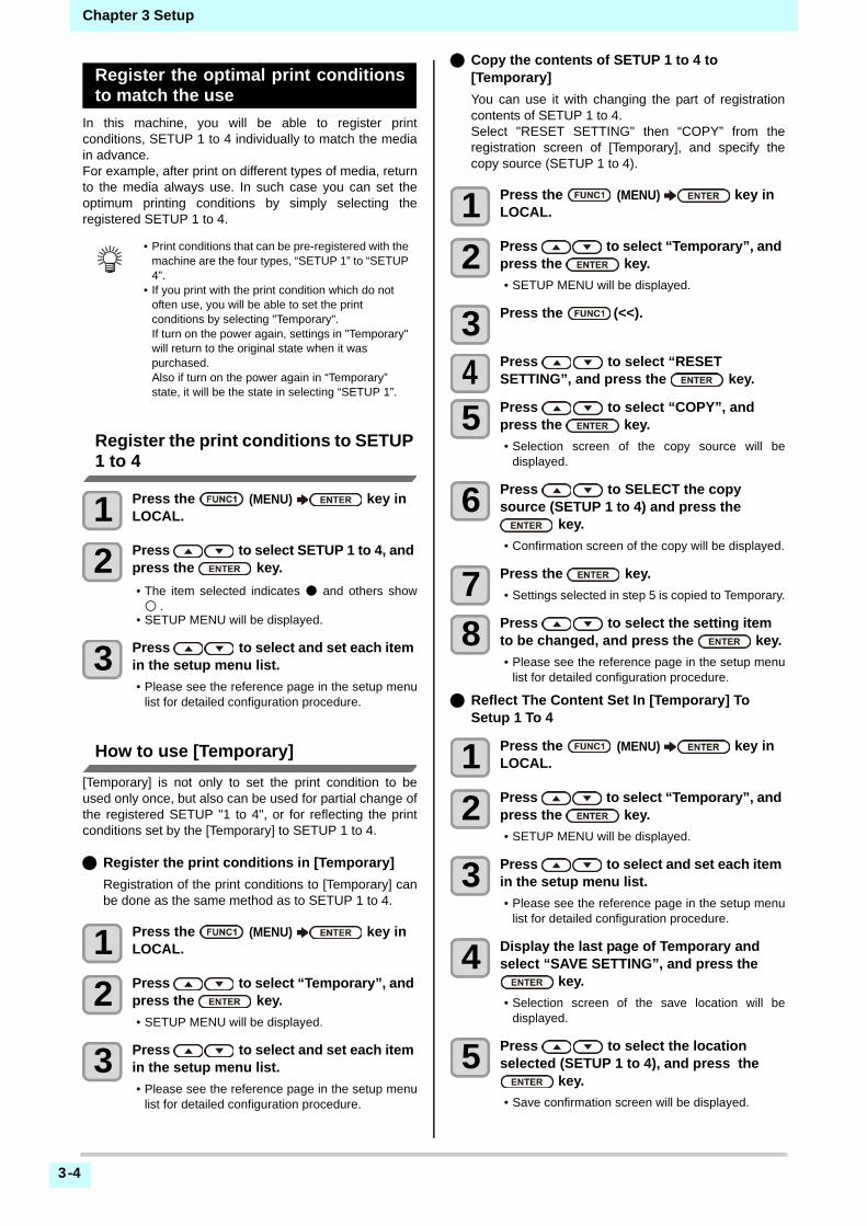
3-4
Chapter 3 Setup
Register the optimal print conditionsto match the use
In this machine, you will be able to register printconditions, SETUP 1 to 4 individually to match the mediain advance.For example, after print on different types of media, returnto the media always use. In such case you can set theoptimum printing conditions by simply selecting theregistered SETUP 1 to 4.
Register the print conditions to SETUP 1 to 4
1 Press the (MENU) key in LOCAL.
2 Press to select SETUP 1 to 4, and press the key.
• The item selected indicates ● and others show○ .
• SETUP MENU will be displayed.
3 Press to select and set each item in the setup menu list.
• Please see the reference page in the setup menulist for detailed configuration procedure.
How to use [Temporary]
[Temporary] is not only to set the print condition to beused only once, but also can be used for partial change ofthe registered SETUP "1 to 4", or for reflecting the printconditions set by the [Temporary] to SETUP 1 to 4.
Register the print conditions in [Temporary]
Registration of the print conditions to [Temporary] canbe done as the same method as to SETUP 1 to 4.
1 Press the (MENU) key in LOCAL.
2 Press to select “Temporary”, and press the key.
• SETUP MENU will be displayed.
3 Press to select and set each item in the setup menu list.
• Please see the reference page in the setup menulist for detailed configuration procedure.
Copy the contents of SETUP 1 to 4 to [Temporary]
You can use it with changing the part of registrationcontents of SETUP 1 to 4.Select "RESET SETTING" then “COPY” from theregistration screen of [Temporary], and specify thecopy source (SETUP 1 to 4).
1 Press the (MENU) key in LOCAL.
2 Press to select “Temporary”, and press the key.
• SETUP MENU will be displayed.
3 Press the (<<).
4 Press to select “RESET SETTING”, and press the key.
5 Press to select “COPY”, and press the key.
• Selection screen of the copy source will bedisplayed.
6 Press to SELECT the copy source (SETUP 1 to 4) and press the
key.
• Confirmation screen of the copy will be displayed.
7 Press the key.
• Settings selected in step 5 is copied to Temporary.
8 Press to select the setting item to be changed, and press the key.
• Please see the reference page in the setup menulist for detailed configuration procedure.
Reflect The Content Set In [Temporary] To Setup 1 To 4
1 Press the (MENU) key in LOCAL.
2 Press to select “Temporary”, and press the key.
• SETUP MENU will be displayed.
3 Press to select and set each item in the setup menu list.
• Please see the reference page in the setup menulist for detailed configuration procedure.
4 Display the last page of Temporary and select “SAVE SETTING”, and press the
key.
• Selection screen of the save location will bedisplayed.
5 Press to select the location selected (SETUP 1 to 4), and press the
key.
• Save confirmation screen will be displayed.
• Print conditions that can be pre-registered with the machine are the four types, “SETUP 1” to “SETUP 4”.
• If you print with the print condition which do not often use, you will be able to set the print conditions by selecting "Temporary".If turn on the power again, settings in "Temporary" will return to the original state when it was purchased.Also if turn on the power again in “Temporary” state, it will be the state in selecting “SETUP 1”.

3-5
3
2
2
2
Chapter 3 Setup
6 Press the key.
• Settings of Temporary will be saved to the locationselected in step 5.
7 Press the key several times to end the setting.
Reset the registered contents
Reset the contents registered to SETUP 1 to 4.
1 Press the (MENU) key in LOCAL.
2 Press to select SETUP 1 to 4 to be reset and press the key.
• SETUP MENU will be displayed.
3 Press the (<<).
4 Press to select “RESET SETTING”, and press the key.
• Confirmation screen of reset settings will bedisplayed.
5 Press the key several times to end the setting.
Setting of Media Correction
Correct the media feed amount to match the type ofmedia you are using.If the correction value is not appropriate, stripes mayappear on the printed image, thus resulting in a poorprinting.
A pattern for media correction is printed and a media-feeding rate is corrected.
1 Set a media. ( P.2-4)
2 Press the (MENU) key in LOCAL.
3 Press to select SETUP 1 to 4, and press the key.
• SETUP MENU will be displayed.
4 Press to select “FEED COMP”, and press the key.
5 Press the key twice to print a correction pattern.
6 Check the correction pattern and enter a correction value.
• A screen for entering the correction value will bedisplayed.
• Enter a correction value in "+":The boundary between the two bands is widened.
• Enter a correction value in "-":The boundary between the two bands isnarrowed.
• When you change the correction value by "30", thewidth of the boundary changes by about 0.1 mm.
7 Press the key.
• Print a correction pattern again and check it.• When media correction is needed, perform the
operation in Step 6 to make correction.
8 Press the key several times to end the setting.
Correcting Media-feeding during Printing
A media-feeding rate can be corrected even in the remotemode or when image data is printed.
1 Press the (ADJUST) key inthe Remote.
2 Press to enter a corrected feeding rate.
• Corrected feeding rate: -9999 to 9999• The value entered here is reflected in the
corrected feeding rate soon.
3 Press the twice key.
• key. The changed value is registered.• When you press the [ENTER] key instead of the
[END] key, the value entered here will be validtemporarily.(When you perform media detectionagain or turn the power OFF, the correction valueis cleared.)
• On completion of [MEDIA COMP.] during use of a roll media, the media returns to the printing origin. Then the roll media in the rear of this machine will slacken.Before printing, take up the slack in the roll media by hand; a loose roll media can result in an inferior image quality.
• When printing with a take-up device, set the media first and perform media correction.
• Two bands are printed in the correction pattern.• Make adjustment so that an even color density is
obtained in the boundary between the two bands.
Second band
First band Med
ia fe
ed d
irect
ion

3-6
Chapter 3 Setup
If the Positions of Dots Shift...
When the condition for printing (media thickness/ink type/etc.) has been changed, perform the following operationto correct the ink drop position for bidirectional (Bi)printing and obtain the proper printing result.
Example of a Printed Pattern
1 Set a media on the machine. ( P.2-4)
• In order to print a pattern, a media that is 500 mmwide at least is necessary.
2 Press the (MENU) key in LOCAL.
3 Press to select SETUP 1 to 4, and press the key.
• SETUP MENU will be displayed.
4 Press to serect “DROP.POScorrect” , and press the key.
5 Press the key.
• Start the pattern printing.• Multiple test patterns are printed. (The printed
patterns are called Pattern 1, Pattern 2, Pattern3... in the order of printing.)
6 Press to enter a correction value of Pattern 1, and press the key.
• Corrected feeding rate: -40 to 40• Check the test patterns. The position where an
outward feeding line and a return feeding linebecome one straight line is the correction value.
• When the correction value in not between -40 and40, adjust the height of the printing heads andperform the operations in Step 2 and later.
7 In the same way as in Step 4, enter a correction value of Pattern 2 and later, and press the key.
8 Press the key several times to end the setting.
Setting the HEATER
Pre-heater /Print heater / Post-heater are equipped on theplaten.
Here, in addition to the temperature setting of eachheater, the time from the print completion until the heaterto be OFF can be set up.
1 Press the (MENU) key in LOCAL.
2 Press to select SETUP 1 to 4, and press the key.
• SETUP MENU will be displayed.
3 Press to serect “HEATER” , and press the key.
4 Set each heater temperature by pressing .
• Heater selecting : by the [][] keys• Temperature setting : by the [][] keys
5 Press to serect “OFFTIME” , and press the key.
6 Press , set the time until the heater to be OFF after printing, and press the key
7 Press the key several times to end the setting.
The dots at the fourth position counted from the zero position in the positive direction form a straight line.In this case, the dot position correction value is 4.0.
Output direction
Type of HEATER Function
Pre-heaterUsed for pre-heating of the media prior to printing to prevent rapid temperature changing.
Print-heater Improves the image quality in printing.
Post-heater Dries ink after printing.
• press [FUNC3] (off) in Step 3 to turn all heaters OFF.or, press [FUNC1] to raise all heaters by 10°C.
• If press keys or receive data during OFF is set in step 6, automatically returns to the set temperature.

3-7
3
2
2
2
Chapter 3 Setup
Setting of Logical Seek
The head’s operation varies depending on the LOGICALSEEK settings, as shown in the figure below.
1 Press the (MENU) key in LOCAL.
2 Press to select SETUP 1 to 4, and press the key.
• SETUP MENU will be displayed.
3 Press to serect “LOGICAL SEEK” , and press the key.
4 Press to select a set value, and press the key.
• Set value : HOST / ON / OFF
5 Press the key several times to end the setting.
Setting of Drying Time
In the drying time setting, the following items for ink dryingtime are set.
• SCAN : Ink drying time for each scanning is set. (During bidirectional printing, the machine stops for a certain period of time specified for each of the outward and return scanning.)
• PRINT END : Ink drying time for after printing is set.
1 Press the (MENU) key in LOCAL.
2 Press to select SETUP 1 to 4, and press the key.
• SETUP MENU will be displayed.
3 Press to select “DRYING TIME”, and press the key.
4 Press the key.
5 Press to set drying time, and press the key.
• Set the drying time for canning and after printingis completed. To enable the drying time specifiedin your RIP, select “Host”.
• Scanning setting value : Host or 0.0 sec. to 9.9 sec.
• Print end setting value:Host or 0 sec. to 120 min.
• Item selecting:by the [][] keys• Time setting:by the [][] keys
6 Press the key several times to end the setting.
UNI-DIRECTIONAL BI-DIRECTIONAL
Movement of heads when LOGICAL seek is OFF
Movement of heads when LOGICAL seek is ON
UNI-DIRECTIONAL BI-DIRECTIONAL
Media
Red arrow :Movement of head
Print erea
Red arrow :Movement of head
Print erea
Media
Media Media
• When you give priority to the setting at the RasterLink side, make the setting value “Host”.
• “SCAN” set in this machine is displayed as “Pause Time per Scan” in the RasterLink.
• You cannot specify the print end at the RasterLink side. When you set this machine to “Host”, printing will be performed in “PRINT END= 0 sec.” status.

3-8
Chapter 3 Setup
Setting of Left and Right Margins
Set a non-printing area along the left and right edges ofthe media.The offset value against the standard margin 15mm is sethereupon.
1 Press the (MENU) key in LOCAL.
2 Press to select SETUP 1 to 4, and press the key.
• SETUP MENU will be displayed.
3 Press the (>>).
4 Press to serect “Margin/L” or “Margin/R” , and press the key.
5 Press to select a set value, and press the key.
• Set value : HOST / -10 to 85 mm
6 Press the key several times to end the setting.
Setting of Vacuum Fan
Sets the absorbability of the media.By setting the absorption power to match the media, youcan prevent print errors due to media rise-up.
1 Press the (MENU) key in LOCAL.
2 Press to select SETUP 1 to 4, and press the key.
• SETUP MENU will be displayed.
3 Press the (>>).
4 Press to serect “VACUUM FAN” , and press the key.
5 Press the key.
6 Press to select a set value, and press the key.
• Set value : HOST/WEAK /STANDARD/ STRONG
7 Press the key several times to end the setting.
Setting of Feed Speed
Changes the media feeding speed in printing.
1 Press the (MENU) key in LOCAL.
2 Press to select SETUP 1 to 4, and press the key.
• SETUP MENU will be displayed.
3 Press the (>>).
4 Press to serect “FEED SPEED” , and press the key.
5 Press the key.
6 Press to select a set value, and press the key.
• Set value : HOST / 10 to 200%
7 Press the key several times to end the setting.
Setting of MAPS
The MAPS (Mimaki Advanced PassSystem) function todisperse the pass boundary to make the feeding stripesless visible.With this function, the degree of application of MAPS canbe changed.
• When you give priority to the setting at the RIP software side, make the setting value “Host”.
• You cannot specify the margins at the attached RIP software (RasterLink). When you use the RasterLink, if you set this machine to “Host”, printing will be performed in “Margins for right and left off set value= 0 mm” status.
• The margin setting is reflected when the media width is detected.
• Pay attention to that printing may start on the media press if a right and left margin is set to 5 mm or less when the media press is used in printing.
• MAPS provides two setting options: “AUTO” and "MANUAL" MAPS applies the one most suitable for your printing conditions, so please normally use "AUTO" (default value).
• In order to use this function, Mimaki driver Ver 4.2.0 or higher is required.
• Changing the MAPS settings may change the color tone. Check the effects before use.
• MAPS may not be effective depending on image to be printed. Use it after checking effect in advance.

3-9
3
2
2
2
Chapter 3 Setup
Setting Auto Cleaning
You can set the machine so that it counts the number ofprinted files or the length or time after printing has beencompleted, and performs cleaning automatically if required.You can select the auto cleaning setting from three typesbelow:
• PAGE : Set the cleaning intervals by the number of printed files.
• LENGTH : Set the cleaning intervals by the printed length.
• TIME : Set the cleaning intervals by the printed time.
The machine can perform a stable printing operation withits heads always kept clean.Besides, automatic nozzle check after auto cleaning canbe set. (Cleaning Check function)The machine can perform a stable printing operation withits heads always kept clean.
1 Press the (MENU) key in LOCAL.
2 Press to select SETUP 1 to 4, and press the key.
• SETUP MENU will be displayed.
3 Press the (>>) .
4 Press to select “AUTO CLEANING”, and press the key.
5 Press key, and press to select the type of auto cleaning.
• There are “PAGE”, “LENGTH” and “TIME” forauto cleaning.
• FILE:When the set number of prints has beencompleted, the machine performs head cleaningautomatically.
• LENGTH:When the set length has passed, themachine performs head cleaning automatically.
• TIME:When the set time has passed, the machineperforms head cleaning automatically.
• If you do not set auto cleaning, first select “OFF”and proceed to the Step 7.
6 Press key, and press to select the cleaning interval.
• Depending on the auto cleaning type selected inthe Step 3, the setting value differs.
• For FILE : 1 to 1000 file• For LENGTH : 0.1 to 100.0m (in 0.1m increment)• For TIME : 10 to 120min (in 10min increment)
7 Press key, and press to select the cleaning type.
• Set Value : NORMAL/ SOFT/HARD
8 Press key, and press to select “Cleaning Check”.
9 Press key, and press to select set value.
• Set Value : ON/ OFF
10 Press the key.
11 Press the key several times to end the setting.
Setting Interval wiping
When the set time has passed, nozzle face of the head iscleaned automatically to remove ink droplets on thenozzle face.In case that deflection, nozzle missing, or symptom whichink droplets fall down occurred, set the interval betweeneach operation shorter.
1 Press the (MENU) key in LOCAL.
2 Press to select SETUP 1 to 4, and press the key.
• SETUP MENU will be displayed.
3 Press the (<<) .
4 Press to serect “INTERVAL WIPING” , and press the key.
5 Press to set intervals.
• Set Value : 3 to 255 Minutes, OFF• When [OFF] is set, periodical wiping is not
executed.
6 Press the key.
7 Press the key several times to end the setting.
• Depending on the state of the heads, etc., the image quality deterioration may not be improved even with this function performed.In this case, contact our service office or the distributor in your region.
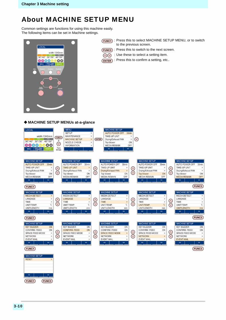
3-10
Chapter 3 Machine setting
About MACHINE SETUP MENUCommon settings are functions for using this machine easily.The following items can be set in Machine settings.
: Press this to select MACHINE SETUP MENU, or to switchto the previous screen.
: Press this to switch to the next screen.
: Use these to select a setting item.
: Press this to confirm a setting, etc..
MACHINE SETUP MENUs at-a-glance

3-11
3
2
2
2
Chapter 3 Machine setting
MACHINE SETUP MENU table
Function name Set value Default Meaning
AUTO Power-off ( P.3-12)NONE/10 ~ 600min
30minWhen no operation has been performed for the set time, the power supply is automatically turned “OFF”.
TAKE-UP UNIT( P.3-12)
TAKE-UP UNIT ON/ OFF ONFor setting whether the take-up unit is used or not used.
TAKE-UP SW Continuance/ TemporaryContinuance
Set the operation method when press the ON / OFF button on the take-up unit.
Drying/Exhaust FANSet this when you use the optional drying/exhaust fan. For details, refer to the user manual supplied with the drying/exhaust fan.
TOP BLOWER( P.3-12) ON / OFF ON Set the operation of the top blower in print.
(ON) STRENGTH AUTO/WEAK/STANDARD AUTO Set the strength of the top blower in print.
MEDIA REMAIN ( P.3-13) ON/ OFF OFF You can control the remaining amount of media.
MEDIA DETECT( P.3-13)
DETECTION TYPE AUTO/MANUAL AUTO Set the media detection method.
USE PR NUMBER QUERY
ON / OFF ONSet whether or not to enter the number of the pinch rollers you are using during media detection.
LANGUAGE ( P.3-14) English / 日本語 English Displayed language is changed.
TIME ( P.3-14) +4h ~ -20h Japan time Time difference is corrected.
UNIT/ TEMP. ( P.3-14) °C (Centigrade)/°F (Fahrenheit) °C A unit for displaying temperature is set.
UNIT/ LENGTH ( P.3-14) mm / inch mm A unit for displaying length and area is set.
KEY BUZZER ( P.3-14) OFF / ON ON A buzzer sound when keys are pressed is set.
CONFIRM. FEED ( P.3-15) ON / OFF ONSet whether media feeding is performed for checking the result of the test printing etc. or not.
SPACE FEED MODE ( P.3-15)INTERMITTENT / CONTINUOUS
INTERMITTENT
Change the feed mode of the margin included in the image data.
NETWORK( P.3-15)
Set the network.
Check IP Addr. The IP address currently used by this machine is displayed.
Check MAC Addr. The IP address currently used by this machine is displayed.
DHCP ON / OFFWhen it is ON, the IP address given by the DHCP server is used.
AutoIP ON / OFFWhen it is ON, the IP address is determined by the AutoIP protocol. However, DHCP is ON, DHCP has priority.
IP Address *1 Set the IP address used by this machine.
Default Gateway *1 Set the default gateway used by this machine.
DNS Address *1 Set the DNS server address used by this machine.
SubNet Mask *1 Set the digit number of the subnet mask used by this machine.
EVENT MAIL
Mail Delivery( P.3-16)
ON / OFF OFFSet whether you send/ do not send the e-mail when the set event occurs.
Select Event( P.3-17)
Print Start Event
ON / OFF OFFSet whether you send/ do not send the e-mail at the start of printing.
Print End Event ON / OFF OFFSet whether you send/ do not send the e-mail at the end of printing.
Error Event ON / OFF OFFSet whether you send/ do not send the e-mail when a error occurs.
Warning Event ON / OFF OFFSet whether you send/ do not send the e-mail when a warning occurs.
Other Event ON / OFF OFFSet whether you send/ do not send the e-mail when an event other than the above occurs.
Mail Address( P.3-17)
Set the e-mail address to which you send the event mail.
Alphanumeric characters and symbols (within 96 characters)
Message Subject( P.3-17)
Set the characters to write in the subject of the event mail.
Alphanumeric characters and symbols (within 8 characters)
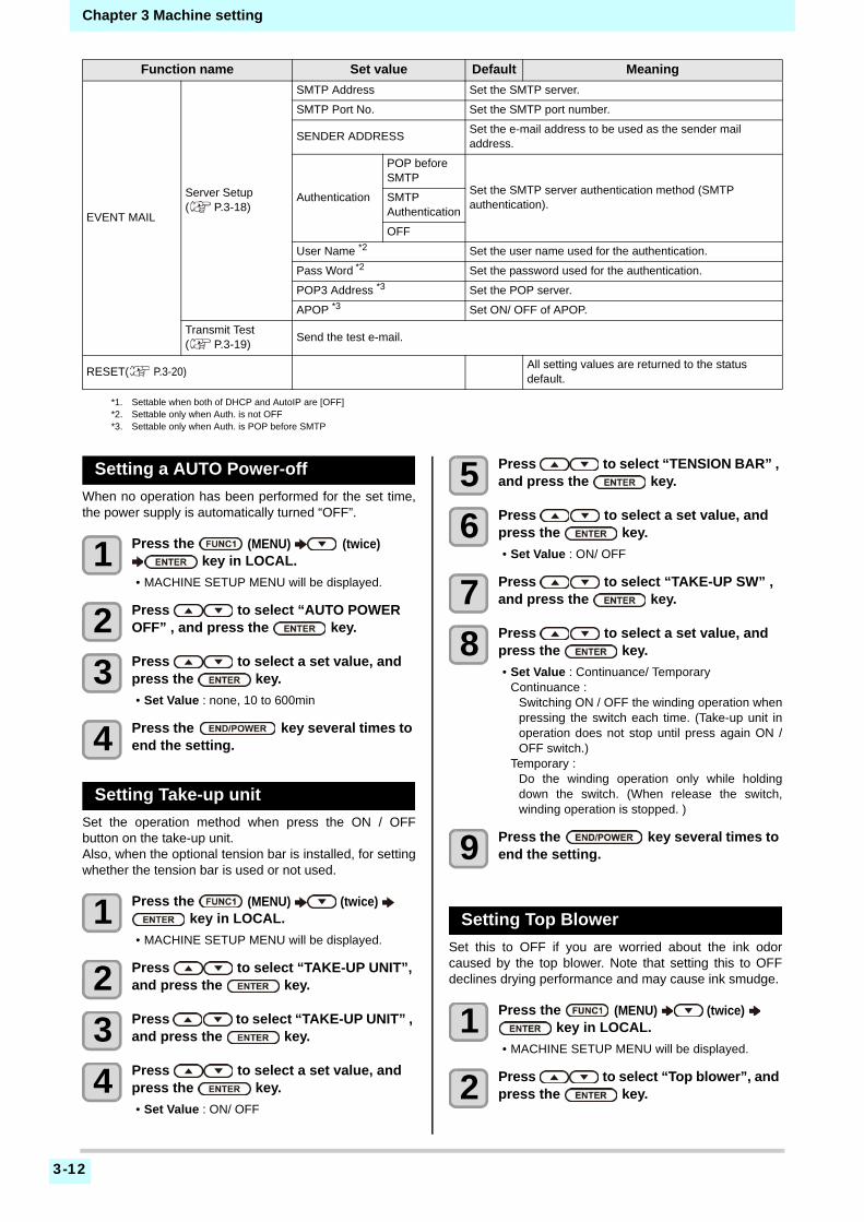
3-12
Chapter 3 Machine setting
Setting a AUTO Power-off
When no operation has been performed for the set time,the power supply is automatically turned “OFF”.
1 Press the (MENU) (twice) key in LOCAL.
• MACHINE SETUP MENU will be displayed.
2 Press to select “AUTO POWER OFF” , and press the key.
3 Press to select a set value, and press the key.
• Set Value : none, 10 to 600min
4 Press the key several times to end the setting.
Setting Take-up unit
Set the operation method when press the ON / OFFbutton on the take-up unit.Also, when the optional tension bar is installed, for settingwhether the tension bar is used or not used.
1 Press the (MENU) (twice) key in LOCAL.
• MACHINE SETUP MENU will be displayed.
2 Press to select “TAKE-UP UNIT”, and press the key.
3 Press to select “TAKE-UP UNIT” , and press the key.
4 Press to select a set value, and press the key.
• Set Value : ON/ OFF
5 Press to select “TENSION BAR” , and press the key.
6 Press to select a set value, and press the key.
• Set Value : ON/ OFF
7 Press to select “TAKE-UP SW” , and press the key.
8 Press to select a set value, and press the key.
• Set Value : Continuance/ TemporaryContinuance :
Switching ON / OFF the winding operation whenpressing the switch each time. (Take-up unit inoperation does not stop until press again ON /OFF switch.)
Temporary :Do the winding operation only while holdingdown the switch. (When release the switch,winding operation is stopped. )
9 Press the key several times to end the setting.
Setting Top Blower
Set this to OFF if you are worried about the ink odorcaused by the top blower. Note that setting this to OFFdeclines drying performance and may cause ink smudge.
1 Press the (MENU) (twice) key in LOCAL.
• MACHINE SETUP MENU will be displayed.
2 Press to select “Top blower”, and press the key.
EVENT MAIL
Server Setup( P.3-18)
SMTP Address Set the SMTP server.
SMTP Port No. Set the SMTP port number.
SENDER ADDRESSSet the e-mail address to be used as the sender mail address.
Authentication
POP before SMTP
Set the SMTP server authentication method (SMTP authentication).
SMTP Authentication
OFF
User Name *2 Set the user name used for the authentication.
Pass Word *2 Set the password used for the authentication.
POP3 Address *3 Set the POP server.
APOP *3 Set ON/ OFF of APOP.
Transmit Test( P.3-19)
Send the test e-mail.
RESET( P.3-20) All setting values are returned to the status default.
*1. Settable when both of DHCP and AutoIP are [OFF]*2. Settable only when Auth. is not OFF*3. Settable only when Auth. is POP before SMTP
Function name Set value Default Meaning

3-13
3
2
2
2
Chapter 3 Machine setting
3 Press to select ON, and press the key.
• Sect "ON" and it allows to select "strength".• “Select OFF to not set top blower. Proceed to
Step 6.
4 Press to select “strength"and press the key.
• Set Value : AUTO / WEAK / STANDARD
5 Press the key several times to end the setting.
Setting the Display of Media Residual
Whether the screen displays the remaining amount of amedia is set.
1 Press the (MENU) (twice) key in LOCAL.
• MACHINE SETUP MENU will be displayed.
2 Press to select “MEDIA REMAIN”, and press the key.
3 Press to select ON/OFF.
4 Press the key.
5 Press the key several times to end the setting.
Setting the Display of Media Detec-tion
Set the following two items in media detection settings.
1 Press the (MENU) (twice) key in LOCAL.
• MACHINE SETUP MENU will be displayed.
2 Press the (>>).
3 Press to select “MEDIA DETECT”, and press the key.
4 Press to select “MEDIA DETECT” , and press the key.
5 Press to select AUTO/MANUAL.
6 Press the key.
7 Press to select “USE PR NUMBER QUERY”, and press the key.
8 Press to select ON/OFF.
9 Press the key.
10 Press the key several times to end the setting.
• Basically, we recommend using the top blower by selecting "AUTO". An appropriate level of strength will be applied according to the ink type and profile*1 you are using.*1) When using RL6
• When using top blower in Sb54 ink set, if bleeding or the like occurs, set to "WEAK".When "WEAK" is selected, bleeding may be eliminated.
• If you mind the smell of ink, use by turning the top blower setting OFF. Note that when the machine is used with the top blower setting turned OFF, its drying performance goes down.
When the media remaining amount display is turned to "ON"
the remaining amount of a media is displayed in Remote.(However, when a leaf media is used, the length of the media to be printed is displayed.)
When the media remaining amount display is turned to "OFF"
the remaining amount of a media is not displayed in the Remote.
• The amount of a media that has been fed by the printing and jog keys is reflected in the remaining amount of a media.
• The length of a media (initial value of the remaining amount) is entered when a roll media is detected.( P.2-11)
• The setting configured here does not become effective unless media detection is performed after the setting has been complete.
Setting of Media Detection
When loading the media, set whether to detect the media width automatically (AUTO) or decide the print (or cut) range manually (MANUAL).
USE PR NUMBER QUERY
Set whether or not to enter the number of the pinch rollers you are using during media detection.
• When using the media that cannot be detected by the sensor, such as black cutting sheets, set the media detection setting to "MANUAL".
• If you set the input of the number of pinch rollers “OFF” in step 8, the pinch roller pressure and the number of use, that has been set in RasterLink6, may not match in some cases. Set to “OFF” only when performing set of pinch roller pressure ( P.2-11) in this machine.
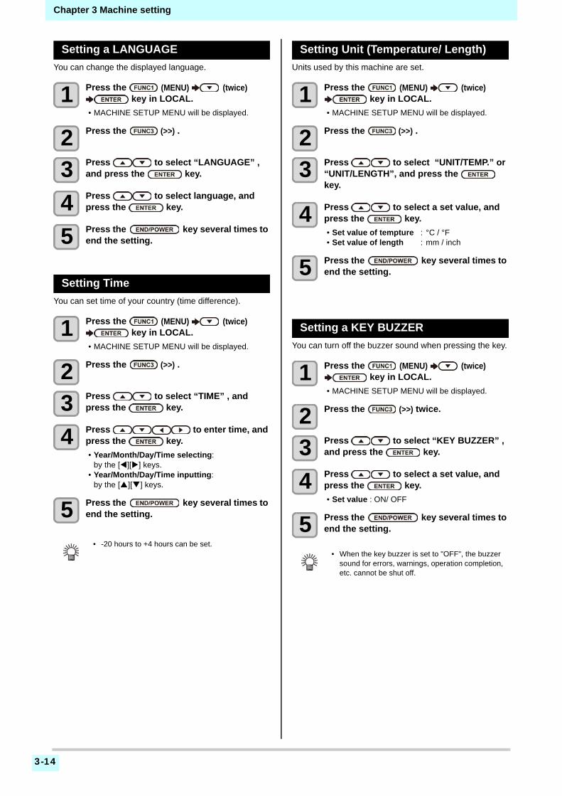
3-14
Chapter 3 Machine setting
Setting a LANGUAGE
You can change the displayed language.
1 Press the (MENU) (twice) key in LOCAL.
• MACHINE SETUP MENU will be displayed.
2 Press the (>>) .
3 Press to select “LANGUAGE” , and press the key.
4 Press to select language, and press the key.
5 Press the key several times to end the setting.
Setting Time
You can set time of your country (time difference).
1 Press the (MENU) (twice) key in LOCAL.
• MACHINE SETUP MENU will be displayed.
2 Press the (>>) .
3 Press to select “TIME” , and press the key.
4 Press to enter time, and press the key.
• Year/Month/Day/Time selecting:by the [][] keys.
• Year/Month/Day/Time inputting:by the [][] keys.
5 Press the key several times to end the setting.
Setting Unit (Temperature/ Length)
Units used by this machine are set.
1 Press the (MENU) (twice) key in LOCAL.
• MACHINE SETUP MENU will be displayed.
2 Press the (>>) .
3 Press to select “UNIT/TEMP.” or “UNIT/LENGTH”, and press the key.
4 Press to select a set value, and press the key.
• Set value of tempture : °C / °F• Set value of length : mm / inch
5 Press the key several times to end the setting.
Setting a KEY BUZZER
You can turn off the buzzer sound when pressing the key.
1 Press the (MENU) (twice) key in LOCAL.
• MACHINE SETUP MENU will be displayed.
2 Press the (>>) twice.
3 Press to select “KEY BUZZER” , and press the key.
4 Press to select a set value, and press the key.
• Set value : ON/ OFF
5 Press the key several times to end the setting.
• -20 hours to +4 hours can be set.• When the key buzzer is set to "OFF", the buzzer
sound for errors, warnings, operation completion, etc. cannot be shut off.
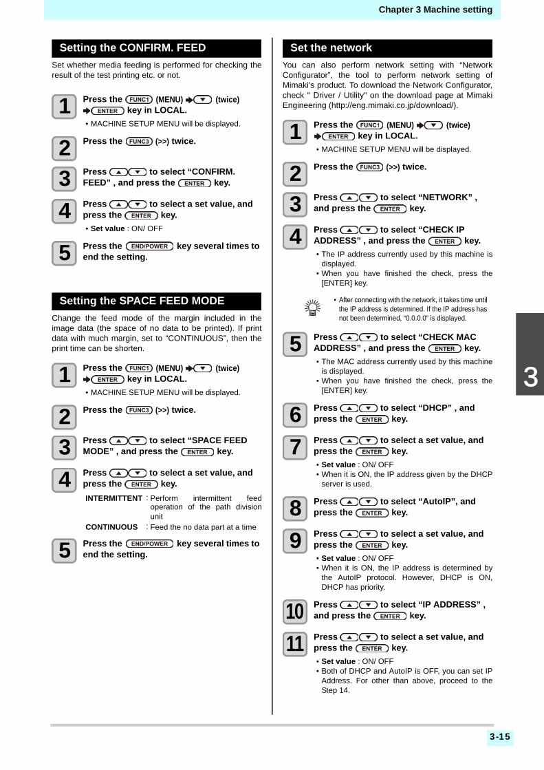
3-15
3
2
2
2
Chapter 3 Machine setting
Setting the CONFIRM. FEED
Set whether media feeding is performed for checking theresult of the test printing etc. or not.
1 Press the (MENU) (twice) key in LOCAL.
• MACHINE SETUP MENU will be displayed.
2 Press the (>>) twice.
3 Press to select “CONFIRM. FEED” , and press the key.
4 Press to select a set value, and press the key.
• Set value : ON/ OFF
5 Press the key several times to end the setting.
Setting the SPACE FEED MODE
Change the feed mode of the margin included in theimage data (the space of no data to be printed). If printdata with much margin, set to “CONTINUOUS”, then theprint time can be shorten.
1 Press the (MENU) (twice) key in LOCAL.
• MACHINE SETUP MENU will be displayed.
2 Press the (>>) twice.
3 Press to select “SPACE FEED MODE” , and press the key.
4 Press to select a set value, and press the key.
INTERMITTENT:Perform intermittent feedoperation of the path divisionunit
CONTINUOUS :Feed the no data part at a time
5 Press the key several times to end the setting.
Set the network
You can also perform network setting with “NetworkConfigurator”, the tool to perform network setting ofMimaki’s product. To download the Network Configurator,check " Driver / Utility" on the download page at MimakiEngineering (http://eng.mimaki.co.jp/download/).
1 Press the (MENU) (twice) key in LOCAL.
• MACHINE SETUP MENU will be displayed.
2 Press the (>>) twice.
3 Press to select “NETWORK” , and press the key.
4 Press to select “CHECK IP ADDRESS” , and press the key.
• The IP address currently used by this machine isdisplayed.
• When you have finished the check, press the[ENTER] key.
5 Press to select “CHECK MAC ADDRESS” , and press the key.
• The MAC address currently used by this machineis displayed.
• When you have finished the check, press the[ENTER] key.
6 Press to select “DHCP” , and press the key.
7 Press to select a set value, and press the key.
• Set value : ON/ OFF• When it is ON, the IP address given by the DHCP
server is used.
8 Press to select “AutoIP”, and press the key.
9 Press to select a set value, and press the key.
• Set value : ON/ OFF• When it is ON, the IP address is determined by
the AutoIP protocol. However, DHCP is ON,DHCP has priority.
10 Press to select “IP ADDRESS” , and press the key.
11 Press to select a set value, and press the key.
• Set value : ON/ OFF• Both of DHCP and AutoIP is OFF, you can set IP
Address. For other than above, proceed to theStep 14.
• After connecting with the network, it takes time until the IP address is determined. If the IP address has not been determined, “0.0.0.0” is displayed.

3-16
Chapter 3 Machine setting
12 Press the key .
• The setting items DEFAULT GATEWAY, DNSADDRESS and SUBNET MASK will be displayed.
• Both of DHCP and AutoIP is OFF, you can setDEFAULT GATEWAY/ DNS ADDRESS/ SUBNETMASK. For other than above, proceed to the Step14.
13 Press the several times to select setting item, and press the key.
14 Press to select a set value, and press the key.
15 Press the key several times to end the setting.
Setting event mail function
Set the function to send e-mails to the set e-mail addresswhen events such as cutting start/ end and stop due to anerror.You can also perform network setting with “NetworkConfigurator”, the tool to perform network setting ofMimaki’s product. To download the Network Configurator,check " Driver / Utility" on the download page at MimakiEngineering (http://eng.mimaki.co.jp/download/).
Enable the event mail function
1 Press the (MENU) (twice) key in LOCAL.
• MACHINE SETUP MENU will be displayed.
2 Press the (>>) twice.
3 Press to select “EVENT MAIL” , and press the key.
4 Press to select “MAIL DELIVERY” , and press the key.
5 Press to select “ON”, and press the key.
6 Press the key several times to end the setting.
• To reflect network setting, once turn off the power supply and turn it on again.
• Disclaimer• The customer is responsible for the communication fee for
Internet communication such as e-mail notification.• The notification by the event mail function may not be
delivered due to Internet environment, failure of the device/ the power supply, etc. Mimaki has absolutely no responsibility for any damages or loss resulting from non-delivery or delays.
• You can use event mail function by connecting LAN to this machine. Please prepare for LAN cable connection beforehand.
• Not compatible with SSL communication.

3-17
3
2
2
2
Chapter 3 Machine setting
Set the event to send an event mail
1 Press the (MENU) (twice) key in LOCAL.
• MACHINE SETUP MENU will be displayed.
2 Press the (>>) twice.
3 Press to select “EVENT MAIL” , and press the key.
4 Press to select “SELECT EVENT” , and press the key.
5 Press to select the event, and press the ().
• After selecting the event, press the [FUNC2] keyand put a check in the check box.An email will be sent when the event whose boxhas been checked occurs.
• To select multiple events, use [][] to put thecursor over the events you want, and put a checkin their boxes by pressing [FUNC2].
6 Press the key several times to end the setting.
Set the e-mail address
1 Press the (MENU) (twice) key in LOCAL.
• MACHINE SETUP MENU will be displayed.
2 Press the (>>) twice.
3 Press to select “EVENT MAIL” , and press the key.
4 Press to select “MAIL ADDRESS” , and press the key.
5 Press to set mail address, and press the key.
• Set the e-mail address to which you send theevent mail.
• Set it with alphanumeric characters and symbolswithin 96 characters.
6 Press the key several times to end the setting.
Set the subject
1 Press the (MENU) (twice) key in LOCAL.
• MACHINE SETUP MENU will be displayed.
2 Press the (>>) twice.
3 Press to select “EVENT MAIL” , and press the key.
4 Press to select “MASSAGE SUBJECT” , and press the key.
5 Press to set subject, and press the key.
• Set the characters to write in the subject of theevent mail.
• Set it with alphanumeric characters and symbolswithin 8 characters.
6 Press the key several times to end the setting.
Event name OutlinePRINT START
Sets sending/not sending of an email when printing starts.
PRINT ENDSets sending/not sending of an email when printing ends.
ERRORSets sending/not sending of an email when printing is stopped due to occurrence of an error.
WARNINGSets sending/not sending of an email when a warning occurs during printing.
etc.Sets sending/not sending of an email when an event other than the above occurs.

3-18
Chapter 3 Machine setting
Set the server
1 Press the (MENU) (twice) key in LOCAL.
• MACHINE SETUP MENU will be displayed.
2 Press the (>>) twice.
3 Press to select “EVENT MAIL” , and press the key.
4 Press to select “SERVER SETUP” , and press the key.
5 Press to select “SMTP ADDRESS” , and press the key.
6 Press to set SMTP Address, and press the key.
• Press the jog key [][][][] to set SMTPaddress.
• Input the SMTP address name.
7 Press to select “SMTP PORT No.” , and press the key.
8 Press to set SMTP Port No., and press the key.
• Set the SMTP port number.
9 Press to select “SENDER ADDRESS” , and press the key.
10 Press to set SENDER ADDRESS, and press the key.
• Press [][][][] and set the e-mail address tobe used as the sender mail address.
• Set it with alphanumeric characters and symbolswithin 64 characters.
11 Press to select “AUTHENTICATION” , and press the
key.
12 Press to set authentication method, and press the key.
• Set the authentication method of the SMTPserver.
• When you select [OFF], proceed to the Step 20.
13 Press to select “USER NAME” , and press the key.
14 Press to set User Name, and press the key.
• Press [][][][] to set the user name to usefor the authentication.
• Set it with alphanumeric characters and symbolswithin 30 characters.
15 Press to select “PASSWORD” , and press the key.
16 Press to set Pass Word, and press the key.
• Press [][][][] to set the password to use forthe authentication.
• Set it with alphanumeric characters and symbolswithin 15 characters.
• When you select [POP before SMTP] in the Step11, set the items in the Step 16 to 19.
17 Press to select “POP3 ADDRESS” , and press the key.
18 Press to set POP3 Address, and press the key.
• Press [][][][] to set POP server.• Input the POP server name.
19 Press to select “APOP” , and press the key.
20 Press to set ON/ OFF, and press the key.
21 Press the key several times to end the setting.
• Depending on your server, if you do not set the e-mail address not supporting the account, sending/ receiving e-mails may be unavailable.
• On the password setting screen, you can only check the value that you are currently inputting.

3-19
1
2
3
4
5
6
Chapter 3 Machine setting
Send a test e-mail
1 Press the (MENU) (twice) key in LOCAL.
• MACHINE SETUP MENU will be displayed.
2 Press the (>>) twice.
3 Press to select “EVENT MAIL” , and press the key.
4 Press the (>>) key.
• “TRANSMIT TEST” will be selected.
5 Press the key.
• The sent result is displayed.• If sending test e-mail has failed, an error code is
displayed.Refer to the next page to solve the problem.
6 Press the key several times to end the setting.
T r a n s m i t T e s t
F a i l e d : 1 2 3 4 5 : e n t
Error code
• The sent result of the test e-mail is the result of e-mail sending process performed by this machine to the e-mail server. It does not indicate that the e-mail was received at the address.
• If the spam e-mail filter etc. has been set in the terminal in which e-mails are received, even if “Sending has been completed” is displayed, the e-mail cannot be received in some cases.
• If sending test e-mail has failed, the error code below is displayed.• If the error cannot be solved, try again after a while.• For the server setting etc., contact with the network administrator or the provider.
Error Code The expected casus Remedy
10 Network connection error
• Check that the machine is connected with the network.• Check that the machine IP address is correct.• Check that the machine is in the environment where
DNS is available.
20 No valid e-mail address. • Enter the correct e-mail address.
1100311004
The POP server cannot be found. Or cannot access DNS server.
• Check the POP server address.• Check that the machine is in the environment where
DNS is available.
11021 Cannot connect with the POP server. • Check the POP server setting.• Check the firewall setting.
12010 An error returns from the POP server. • Check the POP server setting.
13000 The POP authentication has failed.• Check the user name and the password.• Check the APOP setting.• Confirm the authentication method.
1001310014
The SMTP server cannot be found. Or cannot access DNS server.
• Check the SMTP server address.• Check that the machine is in the environment where
DNS is available.
10021 Cannot connect with the SMTP server.• Check the SMTP server setting.• Check the SMTP port number.• Check the firewall setting.
10112021
An error returns from the SMTP server.Or, there was no response.
• Check the SMTP server setting.• Cannot communicate with a server that requires
mandatory SSL communication.• Check protocol filter settings.
12 It is invalid sender address.• Check that the e-mail address supporting the account
entered in the user name/ the password is set in SENDER ADDRESS.
13 The e-mail address cannot be found.Or, it is invalid sender address.
• Check the e-mail address.• Even if there is a mistake in the e-mail address, this error
cannot be detected in some cases.• Check that the e-mail address supporting the account
entered in the user name/ the password is set in SENDER ADDRESS.
2200022008
SMTP authentication error • Confirm the authentication method.
232425
The SMTP authentication has failed.• Check the user name and the password.
“***” is the error code returned from the e-mail server.

3-20
Chapter 3 Machine setting
Initializing the Settings
You can return the setting of “SETUP”, “MAINTENANCE”and “MACHINE SETUP” to the status before shipment.
1 Press the (MENU) (twice) key in LOCAL.
• MACHINE SETUP MENU will be displayed.
2 Press the (<<).
3 Press to select “RESET” , and press the key.
4 Press the key.
• The already configured settings are initialized.
5 Press the key several times to end the setting.
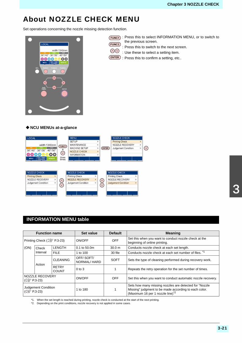
Chapter 3 NOZZLE CHECK
3-21
1
2
3
4
5
6
About NOZZLE CHECK MENUSet operations concerning the nozzle missing detection function.
INFORMATION MENU table
Function name Set value Default Meaning
Printing Check ( P.3-23) ON/OFF OFFSet this when you want to conduct nozzle check at the beginning of online printing.
(ON) Check Interval
LENGTH 0.1 to 50.0m 30.0 m Conducts nozzle check at each set length.
FILE 1 to 100 30 file Conducts nozzle check at each set number of files. *1
*1. When the set length is reached during printing, nozzle check is conducted at the start of the next printing.
Action
CLEANING OFF/ SOFT/NORMAL/ HARD
SOFT Sets the type of cleaning performed during recovery work.
RETRY COUNT
0 to 3 1 Repeats the retry operation for the set number of times.
NOZZLE RECOVERY( P.3-23)
ON/OFF OFF Set this when you want to conduct automatic nozzle recovery.
Judgement Condition ( P.3-23)
1 to 180 1Sets how many missing nozzles are detected for “Nozzle Missing” judgment to be made according to each color. (Maximum 16 per 1 nozzle line)*2
*2. Depending on the print conditions, nozzle recovery is not applied in some cases.
: Press this to select INFORMATION MENU, or to switch tothe previous screen.
: Press this to switch to the next screen.
: Use these to select a setting item.
: Press this to confirm a setting, etc..
NCU MENUs at-a-glance

Chapter 3 NOZZLE CHECK
3-22
Printing Check Flow
Nozzle check is conducted according to the following flow at the start of printing.
Printing Operations at “Nozzle Missing” Judgment and Error Occurrence
When judged to be “Nozzle Missing” Printing is stopped.
When error occurs during nozzle check Printing is stopped and “Printing Check” is automatically turned OFF. After recovering from the error, set “Printing Check” once again.
• Turn the “Printing Check” setting ON to be enabled.• Only perform RETRY COUNT and Printing Check settings when the settings are enabled.
1 nozzle check Judgment
2
3
Recovery operation nozzle check Judgment
4
Retry Judgment
Printing Check Judgment
Detects missing nozzles.
If more missing nozzles than “JudgementCondition ” are detected after the nozzle check,cleaning is performed and nozzle check isconducted again.
5 Nozzle Missing judgment If more missing nozzles than A are eventuallydetected, continued printing will be deemedimpossible and printing will stop.
If more missing nozzles than “Judgement Condition ”are detected after the recovery operation, therecovery operation is conducted again.
• If the “RETRY COUNT” setting is configured to 1 or more, this becomes effective.
Nozzle recovery is automatically conductedfollowing nozzle check and recovery operation.
• Turn the “Printing Check” setting ON to be enabled.

3-23
1
2
3
4
5
6
Chapter 3 NOZZLE CHECK
Setting the Printing Check
Select ON when you want to conduct nozzle check at thestart of online printing.
1 Press the (MENU) (3 times) key in LOCAL.
• NOZZLE CHECK MENU will be displayed.
2 Press to select “Printing Check”, and press the key.
3 Press to select ON, and press the key.
• The “Check Interval” setting screen will bedisplayed.
• “Select OFF to not set nozzle check. Proceed toStep 11.
4 Press the key.
5 Press to select setting item, and press the key.
• select the nozzle check interval from “LENGTH”or “FILE”.LENGTH: nozzle check is conducted when the
printed length reaches the set length.FILE: nozzle check is conducted when the
number of printed files reaches theset number.
6 Press to select setting value, and press the key.
• The set value will differ according to the settingselected in Step 5.LENGTH: 0.1 to 100 mFILE: 0 to 300 files
7 Press the key twice.
• The “Action” setting screen will be displayed.
8 Press the key.
• “CLEANING TYPE” will be selected.
9 Press to select cleaning type, and press the key.
Setting value: OFF/SOFT/ NORMAL/ HARD
10 Press to select retry count, and press the key.
Setting value: 0 to 3
11 Press the key several times to end the setting.
Setting the NOZZLE RECOVERY
set this if you want to conduct automatic nozzle recoverywhen nozzle missing is detected.
1 Press the (MENU) (3 times) key in LOCAL.
• NOZZLE CHECK MENU will be displayed.
2 Press to select “NOZZLE RECOVERY”, and press the key.
3 Press to select ON/OFF, and press the key.
4 Press the key several times to end the setting.
Setting the Judgement Condition
Set the conditions for judging nozzle missing.
1 Press the (MENU) (3 times) key in LOCAL.
• NOZZLE CHECK MENU will be displayed.
2 Press to select “Judgement Condition”, and press the key.
3 Press to select color, and press the key.
4 Press to set the number of nozzles for judgment, and press the
key.
5 Press the key several times to end the setting.
• The type of color changes depending on the ink set.

Chapter 3 INFORMATION MENU
3-24
About INFORMATION MENUThe information of this machine can be confirmed.The following items can be confirmed as machine information.
: Press this to select INFORMATION MENU, or to switch tothe previous screen.
: Press this to switch to the next screen.
: Use these to select a setting item.
: Press this to confirm a setting, etc..

Chapter 3 INFORMATION MENU
3-25
1
2
3
4
5
6
INFORMATION MENU table
Displaying the Information
1 Press the (MENU) (4 times) key in LOCAL.
• INFORMATION MENU will be displayed.
2 Press to select a information.
• Refer to the “INFORMATION MENU”, and select the information to be displayed.
3 Press the key.
• If you selected [LIST] in step 2, the machine’s settings will be printed.
4 Press the key several times to end the setting.
Item Description
USAGE
WIPING This displays how many wipings have been done.
WASTE TANKThis displays how much waste ink has built up in the waste ink tank, as a rough percentage of the tank capacity.
PRINT LENGTH This displays the total length of the printing done to date.
PRINT AREA This displays the total area of the printing done to date.
USE TIME This displays the total time for which the machine has been used to date.
Spout RubberThis displays the total time for which Spout Rubber has been used. (Only displayed when MBIS is used)
VERSION This displays the version information of this machine.
LIST This allows you to print the settings of this machine.
Ink REPL. Report This prints ink history of this machine.
ERROR HISTORYThis displays the history of errors and warnings to date.When you press [][], the date of occurrence (year/month/day/hour/minute) and the error/warning information are displayed alternately in the order of occurrence.
• When you reset the used count of the wiper, press the [FUNC2] key while [RESET?] is displayed. When you press the [ENTER] key, the number of wipings is reset.
• By pressing the function key during display of “WIPING information,” “WASTE TANK information” and “Spout Rubber” in USAGE, the used counts can be reset.When resetting WIPING information: Press the [FUNC2]When resetting WASTE TANK information: Press the [FUNC1]When resetting Spout Rubber: Press the [FUNC3]

Chapter 3 INFORMATION MENU
3-26
This chapter
describes about cutting function.
Cut Out Data with Registration Mark ............4-2The Flow of Cutting out the Registered Data ............................................................. 4-2Enter the registration mark detection mode 4-2Precautions in inputting data with registration marks .......................................................... 4-2Setting of Detecting the Registration Marks 4-6
About CUTTING MENU ................................4-8Cutting MENU table .................................... 4-9
Setting the CUT MODE ...............................4-10perform multiple Cuttings (Copy function) ...4-10SETUP SUB MENU ....................................4-11
Setting the DIVISION CUT ........................ 4-11Make the media without uncut area (OVER CUT function) ............................... 4-13Other SETUP SUB MENU ........................ 4-13SETUP RESET ......................................... 4-14
Maintenance Function .................................4-15Maintenance of Mark Sensor .....................4-15Perform SAMPLE CUT to Find out the Cause of Cutting Error. ..............................4-17Cutting a Medium into Multiple Pieces with a Certain Length ...........................................4-17Cutting out Data without Register Marks (PC ORIGIN OFFSET) ..............................4-18Setting the Scale Adjust .............................4-19
Chapter 4
Cutting Funcion

Chapter 4 Cutting Funcion
4-2
Cut Out Data with Reg-istration MarkCreate registration marks on an output image that youwant to make a seal, and the machine detects them to cutit out.There are following two types of registration marks.
The Flow of Cutting out the Regis-tered Data
Enter the registration mark detectionmode
1 Press the (TEST CUT) in LOCAL.
2 Press to select the “MARK DETECTION”, and press the key.
• It turns out to be a registration mark detectionmode.
Precautions in inputting data withregistration marks
There are some limitations on preparing data withregistration marks.In order to make full use of this function, read the followinginstructions carefully and prepare data with registrationmarks properly.
Size of the registration marks
The registration mark length shall be about more than tentimes the line width.In addition, for the length of a side of the registration markagainst the data, refer to “The size of, and the distancebetween, registration marks” ( P.4-4).
• Use the TP4 when performing trapezium compensation to correct the uneven sheet feeding rate caused by the difference in the diameter between the right and left grit rollers. If the trapezium compensation is to be omitted, there is no need to set the TP4. In that case, however, cutting distortion will increase.
Registration mark: Type 1
Registration mark: Type 2
Add registration marks on the image that you want to make a seal and others, and print it on a sheet.
Set the printed sheet in CJV300 series.
Send the cut-target image from the computer for cutting.
There are some conditions for creating the registration marks. See pages P.4-2 through P.4-5.
Set it referring to P.2-4.
In case it is not successfully cut,• Confirm the reaction
of registration mark sensor.
• Confirm the position of the Light Pointer.
• When the registration detection is set to OFF, it doesn’t enter into the registration mode. ( P.4-6)
• While various functions are under setting, data entry may be cancelled and the machine may go back to the previous setting item.
• The registration mark described here is intended to detect the sheet inclination and the lengths along the X and Y axes. It is not a mark for trimming.
0.5~2.0mm
4~40mm

4-3
Chapter 4 Cutting Funcion
4
2
2
The area where registration marks and designs can be arranged
• The TP1 starting position must be 20 mm or more away from the leading edge of the sheet.
• The TP2 end position must be 45 mm or more away from the tail end of the sheet.
Mark Form : Type 1
Mark Form : Type 2
No-plotting area around the registration marks
An area around a registration mark (from the mark originto the mark size area) is a non-plotting area. There mustbe no data plotted or stain in this area; otherwise, a wrongorigin may be detected or a mark read error can occur.
Available cuttingarea
45 mm or more
A :
Bet
wee
n 5
0 to
30
00 m
m20 mm or more
B : 50 mm or more
The area wherecutting is permitted
The area wherecutting is permitted
Available cuttingarea
45mm+(register mark length / 2) or more
A :
Bet
wee
n 50
to
3000
mm
B : 50 mm or more
20mm+(register mark length / 2) or more
• If a wrong mark origin is detected, the cutting will be performed in a wrong area.
Mark size
Mark Form : Type 1
No-plotting area Mark Mark Origin
Mark Form : Type 2
Mark size
No-plotting area

Chapter 4 Cutting Funcion
4-4
Example of cause of wrong detection 1
There is a line outside the registration marks
Example of cause of wrong detection 2
The distance between registration marks (TP2 and TP1 orTP4 and TP2) is smaller than the mark length (for Type 2)
The size of, and the distance between, registration marks
The size (Y) of a registration mark suited for the distance(X) between the marks is as shown below. If the mark size(Y) is too small relative to the distance (X), the marks maynot be detected correctly. Be sure to prepare theregistration marks with an appropriate size.
(mm)
Distance between registration marks for copied designs
For Type 1 registration marks, the distance between themarks must be not shorter than two times the mark lengthand not longer than 1000 mm. For Type 2 registrationmarks, the distance between the marks must be notshorter than the mark length and not longer than 1000mm.
Recommended size of the area defined with a set of four registration marks
It is recommended that the size of the area defined with aset of four registration marks is in the range of A4 size(210 mm x 297 mm) to A3 size (297 mm x 420 mm). If youfollow this recommendation, you can minimize wastefulspaces and arrange the designs efficiently.
X 200 max. 500 max. 1000 max. 2000 max. 2001 min
B 5 to 40 8 to 40 15 to 40 25 to 40 35 to 40
No-plottingarea
Mark Origin
Detected wrong mark origin
Space largerthan the mark
length
Space larger than the mark length
Mark Form : Type 1
Distance between registration marks = Between mark length (X) x2 and 1000 mm
Distance between registration marks = Between mark length (X) and 1000 mm
Mark Form : Type 2
A4 size (210mm x 297mm) to A3 size (297mm x 420mm)

4-5
Chapter 4 Cutting Funcion
4
2
2
In case of perform printing a registration mark continuously
When perform printing a registration mark continuously,set the one side of the registration marksize to 8mm. Incase 8mm or shorter registration mark recognizedcontinuously, may cause the glitches on the main unit.
Color of mark
The mark must be printed in black against the whitebackground.The registration mark will not be detected correctly if thebackground is not white or the mark is not black.
Mark blurred
If the mark is blurred, a wrong mark origin can bedetected, thus resulting in deviated cutting.
Notes for the combined operation of print & cut
When performing combined operation of print & cut withRasterLink 6 or later, be careful to the following items:
(1) When performing combined operation of print & cut with the attached application software to this device (RasaterLink 6 Ver.3.0 or later / FineCut 8.4.1 or later), the following set contents will follow the instruction of software side. Note that the contents set in this device will be invalid.
• Register mark size• Register mark shape
(2) The combined operation of print & cut without a register mark is not performed under the following conditions:
• Print & cut using the take-up device
8mm or more
• Other than the above conditions, there is a possibility of the cutting line being misaligned depending on the printing data size. Therefore, it is also recommended to perform the operation with the data which has register marks for combined operation of print & cut.

Chapter 4 Cutting Funcion
4-6
Setting of Detecting the RegistrationMarks
When you want to cut the data with registration marks,you must set the following without fail.
1 Press the (MENU) (>>) key in LOCAL.
• Cuttibg MENU will be displayed.
2 Press to select the “MARK DETECT”, and press the key.
3 Press to select the setting item, and press the key.
• Refer to “The setting items of detecting theregistration marks”( P.4-6).
4 Press to select the setting value, and press the key.
• Set value : Standard, high speed, High quality
5 Press the key several times to end the setting.
The setting items of detecting the registration marks
There are the following seven setting items for registrationmark detection.
(1) MARK DETECT
(2) MARK TYPE
Select either one of the following types of registrationmarks.
(3) MARK SIZESet the length of one side of theregistration mark.
• You can set the register mark detection without pressing [FUNC1] (MENU) from LOCAL.
(1) Press the [SEL] key in LOCAL to display"TEST CUT".
(2) Press [FUNC2] (TEST CUT)(3) Press the [ENTER] key
• After this, go to step 3 of "Setting of Detecting the Registration Marks".
Setting Description
ON/OFFThe registration marks can be detected if this is set to ON.
• Use the copy function of cutting software, in the case of continuous cut, select the register mark of Zero margin, and you will be able to place no margin between the register marks.By eliminating the margin between the register marks to cut efficiently, recommend to use register mark shaped “Zero Margin”.
Setting Description
Type 1
Type 2
Zero margin
Setting Description
5 to 40mmWhen the printed mark's horizontal and vertical lengths differ from each other, set the same value as the shorter length.
Length of one side

4-7
Chapter 4 Cutting Funcion
4
2
2
(4) OFFSET Y / OFFSET X
Generally the origin will be set at the position shownbelow.However, depending on your application and the work tobe cut, the cutting position may be misaligned to thesame direction. In this case, the location of the origin canbe corrected.
(5) DETECT END KEY START
(6) SENSOR LEVEL
(7) MARK FILL UP
Setting Description
± 15.00mmUse this to shift the origin position in the X direction or Y direction.
• If the origin is located out of the available cutting area, “ERR37 MARK ORG” will be displayed. In this case, write the registration marks in the area closer to the center of the media.
Setting Description
ON/OFFIf this is ON, you will be able to detect crop mark in [END] key.
• If this is set to ON, the registration mark detection operation may be started by turning the power OFF.
Setting Description
1 to 7
The bigger the numerical value is, the higher the sensitivity of the registration mark sensor becomes.If it detects the registration mark by mistake, lower the sensitivity. Generally, use it with the setting value of “4”.
Setting Description
ON/OFF
Specify the setting as “ON” when using the “Fill around the register mark” function of FineCut to detect the printed registration mark.Create using a registration mark size of 10 mm or more when filling in around the registration mark.
Mark: Type 1 Mark: Type
Orugin
Plus Ydirection
Plus X directionPlus X direction Orugin
Plus Ydirection

Chapter 4 Cutting Funcion
4-8
About CUTTING MENU
: Press this to select SETUP MENU, or to switch to theprevious screen.
: Press this to switch to the next screen.
: Use these to select a setting item.
: Press this to confirm a setting, etc..
Cutting MENUs at-a-glance

4-9
Chapter 4 Cutting Funcion
4
2
2
Cutting MENU table
• For each setting item below, you can set it so that the machine may operate according to the value specified when you printed from your RIP software in the connected host PC.
• Set Item : DRYING TIME/ MARGIN (LEFT and RIGHT)/ VACUUM FAN/ FEED SPEED• When you operate the machine according to the contents specified with the RIP software, set each• item to “Host” when registering this machine type. When you set it other than “Host”, the machine operates according to
the machine setting.• For the specifying method with the RIP software, refer to the operation manual of the RIP software.
Function name Outline
TP DETECT ( P.4-6)
MARK DETECT
When you cut the data with registration marks, you must set without fail.
FORM
SIZE
OFFSET X
OFFSET Y
DETECT END KEY START
SENSOR LEVEL
MARK FILL UP
CUT MODE ( P.4-10) This is to set the cutting quality.
COPY ( P.4-10)This function performs cutting for the received data on two or more sheets.
Tool Change ( P.2-22, P.2-22) You select this function when you replace the tool.
SETUP SUB MENU
DIVISION CUT ( P.4-11)You can cut the data bigger than the sheet width by dividing it.With division cut, you can make settings for the width direction (Y) and feed direction (X).
UP SPEED ( P.4-13)This is to set the speed of sheet and carriage movement when the tool is up. Setting the speed lower makes the sheet misalignment reduced at the time of long sheet feeding.
DUMMY CUT ( P.4-13)The blade edge is made to turn to a specific direction before starting cutting, which allows dummy cutting.
SHEET TYPE ( P.4-13) This is to set the types of sheet according to the sheet you use.
ADJ PRS OFFSET ( P.4-13)This is used to expand the value in such a case as when the beginning and end part of the cut are left cut.
OVER CUT ( P.4-13)By over lapping the start point and the end point arbitrarily, you can make the media without uncut area.
Vacuum fanSet the strength of the vacuum fan at cutting.Please use "weak" normally.
MAINTENANCE
MARK SENSOR ( P.4-15) This is for adjusting the registration mark sensor.
SAMPLE CUT ( P.4-17)In case that normal data cutting cannot be performed etc., perform cutting with the sample stored in this machine to find out the cause of cutting error.
AUTO CUT ( P.4-17) Cutting a medium into multiple pieces with a certain length.
ORIGIN OFFSET ( P.4-18)To print & cut the data without register marks, adjust the misalignment between a printed image and the cutting line.

4-10
Chapter 4 Cutting Funcion
Setting the CUT MODEThis is to set the cutting quality.There are the following three type for cut mode.
1 Press the (MENU) (>>) key in LOCAL.
• Cuttibg MENU will be displayed.
2 Press to select the “CUT MODE”, and press the key.
3 Press to select the setting value, and press the key.
• Set value : Standard, high speed, High quality
4 Press the key several times to end the setting.
perform multiple Cut-tings (Copy function)This function performs cutting for the received data on twoor more sheets.(Maximum 999 cuttings)
• You can perform multiple cuttings by specifying data saved in the receiving buffer of this device.
• The receiving buffer can save only one data.• When a new data is received, the data that has been saved is
overwritten by it. (You cannot perform multiple cuttings by specifying the data that was received before.)
1 Press the (MENU) (>>) key in LOCAL.
• Cuttibg MENU will be displayed.
2 Press to select the “COPY”, and press the key.
3 Press to select the number of cutting (1 to 999), and press the key.
4 Press to select the interval of figures to be cut (0 to 30mm), and press the key.
Setting DescriptionStandard This is a regular cutting mode.
High speedThis is used to perform cutting in a short time (it is not appropriate for the heavy media).
High qualityThis is a cutting mode used to give priority to cutting quality.
• Select “QUALITY” in any of the following cases:• Characters whose sizes are 10 mm or less are to
be cut• Picture patterns or characters that have many
sharp corners are to be cut• Minute cutting is to be performed
However, the edges of finished patterns may be rugged if the data sent from the host computer is too complicated. In such a case, select “HIGHspd” for smooth finish.
• With “QUALITY”, the cutting speed is limited to 20 cm/s.
• If the multiple sheet cutting is executed immediately after cutting in the remote mode, cutting (plotting) will be overlapped. To avoid this trouble, be sure to set the new origin.
• While the machine is executing the multiple sheet cutting, it ignores data sent from the computer.
• To send two or more pieces of data from the computer to the machine, the data has to be sent while providing an interval of 5 seconds or more between any two pieces of data. If two pieces of data are sent from the computer to the machine within 5 seconds, the two pieces of data will be subjected to the multiple sheet cutting. The machine performs cutting for divided cutting data by the specified number of sheets without dividing the data. If any error is displayed, refer to “Error messages” ( P.6-8).
• If there is the origin renewal command in cutting data, you cannot perform copy function.
• When you use FineCut, the default value of Origin Renewal is “ON”. If you perform [No. COPIES], uncheck the checkbox. (Refer to FineCut OPERATION MANUAL Chapter5 “Setting Head Position after Plotting”)
Copyinterval
The origin at executing the multiple sheet cutting. (Manual
The origin at terminating the multiple sheet cutting

4-11
Chapter 4 Cutting Funcion
4
2
2
SETUP SUB MENUThe SETUP SUB MENU offer convenient functions thatyou can use in cutting.The following items are available in the sub menus.
Setting the DIVISION CUT
When you set DIVISION CUT for the width direction (y),you can cut the data bigger than the media width bydividing it. In addition, when you set DIVISION CUT for the feedingdirection (X), you can cut the long data by dividing it andyou can prevent cutting misalignment due to mediameandering.
Set the Y direction (width direction) DIVISION CUT
1 Press the (MENU) (>>) key in LOCAL.
• Cuttibg MENU will be displayed.
2 Press (>>) .
3 Press to select the “SETUP SUB MENU”, and press the key.
4 Press to select the “DIVISION CUT”, and press the key.
5 Press to select “Y”, and press the key.
• If you select “OFF”, setting for division cutting willnot be carried out. Proceed to step 9.
6 Press to select “FRAME CUT”, and press the key.
7 Press to select a set value, and press the key.
• Set value : ON, OFF• Select “ON” for the frame cut.
8 Press to select “MARK CUT”, and press the key.
9 Press to select a set value, and press the key.
• Set value : ON, OFF• Select “ON” for the mark cut.
10 Press the key several times to end the setting.
Function name Outline
DIVISION CUT( P.4-11)
You can cut the data bigger than the sheet width by dividing it.With division cut, you can make settings for the width direction (Y) and feed direction (X).
UP SPEED( P.4-13)
This is to set the speed of sheet and carriage movement when the tool is up. Setting the speed lower makes the sheet misalignment reduced at the time of long sheet feeding.
DUMMY CUT( P.4-13)
You can the blade edge is made to turn to a specific direction before starting cutting, which allows dummy cutting.
SHEET TYPE( P.4-13)
Set this according to the weight of the media you have set. When this is set to "HEAVY", the maximum cutting speed is set low.
ADJ PRS OFFSET( P.4-13)
This is used to expand the value in such a case as when the beginning and end part of the cut are left cut.
OVER CUT( P.4-13)
By over lapping the start point and the end point arbitrarily, you can make the media without uncut area.
SETUP RESET( P.4-14)
Reset the setting values to the initial state.
Vacuum fanSet the strength of the vacuum fan at cutting.Please use "weak" normally.
With the DVISION CUT function, you can use the following convenient functions too.• Perform a frame cut:
Together with the cut data, the machine automatically cuts out the frame fitted to the size of the cut data.
• Put a mark for leaving a margin for gluing: You can put a “mark” for showing the point for gluing together the DIVISION CUT medias.

4-12
Chapter 4 Cutting Funcion
Set the X direction (feeding direction) DIVISION CUT
If the data size of the feeding direction exceeds thedivision length and cross cut length, the machine cuts it atthat position by dividing it.If the cross cut length is set, the machine cuts byoverlapping it by the set value.
1 Press the (MENU) (>>) key in LOCAL.
• Cuttibg MENU will be displayed.
2 Press (>>) .
3 Press to select the “SETUP SUB MENU”, and press the key.
4 Press to select the “DIVISION CUT”, and press the key.
5 Press to select “X”, and press the key.
• If you select “OFF”, setting for division cutting willnot be carried out. Proceed to step 10.
6 Press to select “DIV. LENG”, and press the key.
7 Press to select a set value, and press the key.
• Set value : 50cm to 500 cm (in increments of50cm)
• When it exceeds the set value, the machine cuts itat that position by dividing it.
8 Press to select the “CROSS CUT”, and press the key.
9 Press to select a set value, and press the key.
• Set value : 0mm to 50mm (in increments of 1mm)• The machine cuts by overlapping it by the set
value.
10 Press the key several times to end the setting.
Reset the setting for DIVISION CUT
1 Press the (MENU) (>>) key in LOCAL.
• Cuttibg MENU will be displayed.
2 Press (>>) .
3 Press to select the “SETUP SUB MENU”, and press the key.
4 Press to select the “DIVISION CUT”, and press the key.
5 Press to select “Setting”, and press the key.
6 Press to select “OFF”, and press the key.
7 Press the key several times to end the setting.
• The setting values are kept in memory even when the power is turned off.
• During execution of division cutting, the machine ignores any other data sent from the host computer.
• In any of the following cases, the machine cannot perform division cutting.The data size is larger than the receiver buffer capacity.An origin change command is contained in the cutting data.A two-point compensation value has been set.The registration mark detection is being performed.The machine cuts the test data stored in it.

4-13
Chapter 4 Cutting Funcion
4
2
2
Make the media without uncut area (OVER CUT function)
By over lapping the start point and the end point arbitrarily, you can makethe media without uncut area. Specify the OVER CUT function (valid/invalid) and the length of the OVER CUT. If the length of the OVER CUTis set, when cut starts, cut will be performed from the position to the frontby the specified length and the tool will move up going too far at the end.Additionally, you can enable the corner cut function to perform overcuttingof corners other than the start and end points.
1 Press the (MENU) (>>) key in LOCAL.
• Cuttibg MENU will be displayed.
2 Press (>>) .
3 Press to select the “SETUP SUB MENU”, and press the key.
4 Press to select the “OVER CUT”, and press the key.
5 Press to select the set value, and press the key.
• Set value : OFF/ 0.1 to 1.0m (in 0.1mm increment)
• When you press the [ENTER] key, the setting for“CORNER CUT” setting will be displayed.
6 Press to select ON/OFF, and press the key.
7 Press the key several times to end the setting.
Other SETUP SUB MENU
How to set other convenient functions is explained below. Change the settings according to the types of use.
1 Press the (MENU) (>>) key in LOCAL.
• Cuttibg MENU will be displayed.
2 Press (>>) .
3 Press to select the “SETUP SUB MENU”, and press the key.
4 Press several times, and select an item to set.
• See "List of Settings" to select one.
5 Press the key.
6 Press to select a set value.
• See "List of Settings" to select one.
7 Press the key.
8 Press the key several times to end the setting.
List of Settings
The setting is as follows when purchasing:
• Setting proper OVER CUT can reduce uncut area of start and end point of a media easy to bend. If too large value is set, the result may have a rupture.
OVER CUT : OFF
OVER CUT : 1.0mm
OVER CUT part
Corner cut part
• The set value is retained even when the power is turned "OFF".
Function Name Overview Set Value
Setting the UP SPEED
This is to set the speed of sheet and carriage movement when the tool is up.Setting the speed lower makes the sheet misalignment reduced at the time of long sheet feeding.
5,10,20,30, AUTO (cm/s)
Setting the DUMMY CUT ( P.4-14) the operation of dummy cutting is set. OFF / ON
Setting the SHEET TYPE *1
*1. If you set “Heavy” for the media setting, the cutting speed will be limited to 20 cm/s.
This is to set the types of sheet according to the sheet you use.
Standard / Heavy
Setting the ADJ-PRS OFFSET ( P.4-14)When there is part of a media left uncut at the starting and ending points, the value is increased.
0 to 3 to 7

4-14
Chapter 4 Cutting Funcion
About Dummy Cutting
This is performed after detecting the media or whenchanging the tool type in front of the pinch roller which isnear the both ends from the position of the cutter unit isplaced presently.Set the dummy cutting function to OFF when you do notwant to damage the media in cutting cut-out characters.
About Cutter Blade Corrected Pressure Offset
Some part of a media is left uncut because the pressureapplied when the cutter blade touches the media is weak.When an optional eccentric blade is used, some part of amedia to be cut with the blade's angle being 120 degreesor less may be left uncut.
This is because the corners are cut with a low pressure(about 5 g) automatically applied so that the media doesnot turn up. Some part of a media may be left uncutbecause the blade edge does not rotatesmoothly in its moving direction with the cutting pressurebeing low. In such a case, configure the setting for thepressure to be increased when the corners are cut.
SETUP RESET
Reset the setting values to the initial state.
1 Press the (MENU) (>>) key in LOCAL.
• Cuttibg MENU will be displayed.
2 Press (>>) .
3 Press to select the “SETUP SUB MENU”, and press the key.
4 Press several times, and select an item to set.
• See "List of Settings" to select one.
5 Press (>>) and press the twice.
• “SETUP RESET” will be selected.
6 Press the key.
• The already configured settings are initialized.
7 Press the key several times to end the setting.
• When “PEN” is selected for the tool condition, the dummy cutting cannot be set.
• The default of the dummy cutting function is ON.When you have set the dummy cutting function to OFF, perform test cutting ( P.2-26) to adjust the cutter blade orientation before cutting.
Pinch roller
Dummy cut

4-15
Chapter 4 Cutting Funcion
4
2
2
Maintenance FunctionThis section gathers together the functions for checking/adjusting the cutting accuracy when cutting does not gonormally.
Maintenance of Mark Sensor
If cutting does not go normally, check the items below.?In registration mark sensor maintenance, you can carryout maintenance of the following items.
Check the sensor for the registration mark detection
Prepare the media on which the registration mark isprinted.
1 Press in Local.
• Enter the jog mode
2 Press to move the tip of the pen to the registration mark detection position
• Perform registration mark detection at a position1mm or more away from the registration mark.
3 Press the key to terminate the jog mode.
• The machine returns to the Local.
4 Press the (MENU) (>>) key.
• Cuttibg MENU will be displayed.
5 Press (>>) .
6 Press to select the “MAINTENANCE”, and press the key.
7 Press to select “MARK SENSOR”, and press the key.
8 Press to select “SENSOR CHECK”, and press the key.
9 Select the length of the registration mark and shape of the registration mark detection.
• For details on setting the [SIZE] and [FORM],refer to the ”Setting of Detecting the RegistrationMarks”. ( P.4-6)
10 Press the to perform registration mark detection. ( “Detect operation”)
Function name Outline
MARK sensor( P.4-15)
Adjusting the registration mark sensor.
SAMPLE CUT( P.4-17)
In case that normal hanaokadata cutting cannot be performed etc., perform cutting with the sample stored in this machine to find out the cause of cutting error.
AUTO MEDIA CUT( P.4-17)
You can cut a medium into multiple pieces with a certain length.
PC ORIGIN OFFSET( P.4-18)
Adjust the misalignment between the print origin and the cutting origin.
SCAKLE ADJUST( P.4-19)
When printing and cutting without registration marks, adjustment is performed if the misalignment in the scanning direction occurs between the left and right edges of the media.
Item Outline
SENSOR CHECK( P.4-15)
checking the sensor for the register mark detection.
POINTER OFFSET( P.4-16)
If the cutter unit fails to recognize any register mark properly, the possible cause is an error in the positional relationship between the mark sensor and the light pointer. In this case, correct the position of the light pointer.
• If you move the head and sheet manually, you cannot perform the right response check. Be sure to perform it via the following operations.
• For conditions of already printed registration mark, refer to “Precautions in inputting data with registration marks” ( P.4-2).
• The setting values are kept in memory even when the power is turned off.
• The settings performed here for shape of the registration mark and length of the registration mark are reflected in the settings of “MARK DETECT”.( P.4-6)
• The detection speed selected here will be used in the registration mark detection operations that are executed from here on.
• The pointer offset value selected by this operation is not initialized by SETUP RESET operation.
1 mm or more away Mark detection
position
Mark : Type 1
Mark : Type 2

4-16
Chapter 4 Cutting Funcion
Detect operation
1 Scan in the X direction (plus direction) to detect the line.
• The buzzer sounds when the line is detected. Ifthe line is not detected, the buzzer does notsound.
2 Scan in the X direction (minus direction) to detect the line.
3 Scan in the Y direction (plus direction) to detect the line.
4 Scan in the Y direction (minus direction) to detect the line.
5 Follow the Steps 1 to 4, and confirm if the buzzer sounds 4 times.
• When the detection behavior completessuccessfully, the buzzer sounds 4 times.
• If the buzzer does not sound, contact our salesoffice after checking the registration markcondition.
Correct the light pointer position
If the machine fails to recognize any registration markproperly, the possible cause is an error in the positionalrelationship between the MARK sensor and the lightpointer.In this case, adjust the position of the light pointer.
1 Install a cutter in the tool holder.
2 Load the copy paper.
3 Press the (MENU) (>>) key in LOCAL.
• Cuttibg MENU will be displayed.
4 Press (>>) .
5 Press to select the “MAINTENANCE”, and press the key.
6 Press to select “MARK SENSOR”, and press the key.
7 Press twice to select “POINTER OFS”.
8 Press the key.
• A 10 mm by 10 mm cross pattern will be cutted.• The light pointer turns on and moves to the center
of the cross pattern.
9 Press to adjust the light pointer position so that the center of the light pointer is in alignment with the center of the cross pattern.
10 Press the key.
• The machine will return to the local afterregistering the compensation value.
Minus direction
Plus direction
Mark length
Scan in the Y direction
Minus direction
Plus direction
Scan in the X direction
• The value registered in the [POINTER OFS] is not initialized even by executing the “SETUP RESET”. ( P.4-14)

4-17
Chapter 4 Cutting Funcion
4
2
2
Perform SAMPLE CUT to Find out theCause of Cutting Error.
In case that normal data cutting cannot be performed etc.,perform cutting with the sample stored in this machine tofind out the cause of cutting error.
1 Press the (MENU) (>>) key in LOCAL.
• Cuttibg MENU will be displayed.
2 Press (>>) .
3 Press to select the “MAINTENANCE”, and press the key.
4 Press to select the “SAMPLE CUT”, and press the key.
5 Press to select the SAMPLE DATA to be cut.
• There are two types of samples, “Cut” and“Logo.” If you select “Cut,” proceed to Step 7.
6 Press the key.
7 Select scale factor using to cut Logo.
• Scale factor : 1 to 999%
8 Press the key for starting cutting.
Result of SAMPLE CUT
Sample data can be cut successfully, but other datacannot.The host computer is faulty.Sample data as well as other data cannot be successfullycut either.(When leaving the start/end lines without cuttingoff)Increase the set value of [ADJ-PRS OFS] to raise thepressure for pressing the cutter blade down.
Cutting a Medium into MultiplePieces with a Certain Length
You can cut a medium into multiple pieces with a specifiedlength. (Automatic media-cutting function)
1 Press the (MENU) (>>) key in LOCAL.
• Cuttibg MENU will be displayed.
2 Press (>>) .
3 Press to select the “MAINTENANCE”, and press the key.
4 Press to select the “MEDIA CUT”, and press the key.
5 Press to select a cutting interval, and press the key.
• Set value : 10 to 10,000 mm
6 Press to select a length for the leading end adjustment cutting, and press the key.
• Set value : 0 to 500 mm
7 Press to select the number of times a medium is cut (number of pieces produced by cutting a medium), and press the key.
• Set value : 1 to 9,999• The number of cuts that you set here will be
executed.• You can halt the cutting by pressing the [END/
POWER] key.
8 Press the key several times to end the setting.
• Execution of SAMPLE CUT will clear the data in the receiver buffer.
Sample “Cut”
Sample “Logo”
Function name Outline
Cutting interval Setting the interval for cutting the media.
Leading end adjustment cutting
Setting the length for cutting the medias’ leading edges before auto media cut starts.With edge match cutting, the specified number of media sheets can be cut at equally spaced intervals, even if their leading edges were previously cut to be slanted or uneven.
Number of times a medium is cut
Setting the number of times (sheets) for media cutting.

Chapter 4 Cutting Funcion
4-18
Cutting out Data without Register Marks (PC ORIGIN OFFSET)
Adjust the misalignment between printing and cutting by Print & Cut.Print the adjustment pattern from RasterLink6, and enter the adjustment values to the printer.
For Print & Cut without registration marks
1 Set the machine to "REMOTE" status.
2 Set the print conditions (profile, cut conditions) of the job that you want to print using RasterLink6.
3 Click [print & cut Origin adjust] in the [Cut edit] tab of RasterLink6.
• Click [OK] to print the adjustment pattern.
4 When the pattern is printed, press (ADJUST) and select "PC ORIGIN OFFSET".
• When the media is fed, peal the cut part of the pattern, and check the adjustment values
5 Enter the adjustment values
• When you press the [ENTER] key, the media return, and the operation is completed.
• When printing the data that has a different resolution (Y), make adjustment again. (Save an adjustment value per resolution)
• You cannot print adjustment patterns with multiple conditions continuously, and enter the adjustment values. Make sure you print and set one adjustment value per condition.
Click
X enlarged
Y enlarged
Enter the value of the position that has the least misalignment between top and bottomThe example here shows that -4 has the least misalignment, so enter “-4”.
Enter the value of the position that has the least misalignment between right and leftThe example here shows that 2 has the least misalignment, so enter “2”.

4-19
Chapter 4 Cutting Funcion
4
2
2
For Print & Cut with registration marks
1 Set the machine to "REMOTE" status.
2 Set the print conditions (profile, cut conditions) of the job that you want to print using RasterLink6.
3 Click [print & cut Origin adjust] in the [Cut edit] tab of RasterLink6.
4 Select "Add registration mark".
• Click [OK] to print the adjustment pattern.
5 When the pattern is printed, press (ADJUST) and select "TP OFFSET".
• When the media is fed, peal the cut part of the pattern, and check the adjustment values(The actual pattern has registration marks.)
6 Enter the adjustment values
• When you press the [ENTER] key, the media return, and the operation is completed.
Setting the Scale Adjust
When printing and cutting without registration marks, adjustment is performed if the misalignment in the scanning directionoccurs between the left and right edges of the media.When you perform scale adjustment, adjustment is performed automatically.
1 Set a media ( P.2-4)
• Set the sheet to print the registration mark.
2 Press the key, and press the (ADJUST) in LOCAL.
• ADJUST MENU will be displayed.
3 Press to select the “SCALE ADJUST”, and press the key.
4 Press to select the resolution, and press the key.
5 Press the key several times to end the setting.
X enlarged
Y enlarged
Enter the value of the position that has the least misalignment between top and bottomThe example here shows that -4 has the least misalignment, so enter “-0.40”.
Enter the value of the position that has the least misalignment between right and leftThe example here shows that 2 has the least misalignment, so enter “0.20”.

Chapter 4 Cutting Funcion
4-20

This chapter
describes the items required to use this machine more comfortably, which are themethods for the daily care, the maintenance of the ink cartridges etc.
Maintenance .................................................5-2Precautions for Maintenance ...................... 5-2About Cleaning Solution.............................. 5-2Cleaning the Exterior Surfaces ................... 5-2Cleaning the Platen ..................................... 5-2Cleaning the Media Sensor ......................... 5-3Cleaning the Media Press ........................... 5-3
About MAINTENANCE MENU ......................5-4MAINTENANCE MENUs at-a-glance .......... 5-5
Maintaining the Capping Station ...................5-6Cleaning the Wiper and Cap ....................... 5-6Washing the Head Nozzle ........................... 5-7Washing the Ink Discharge Passage .......... 5-8When the Machine Is Not Used for a Long Time ................................................... 5-8
Cleaning the Ink Head and the Area around It ......................................................5-10Nozzle Recovery Function ..............................5-11
Reset the set value ................................... 5-12Automatic Maintenance Function ................5-12
Setting the Refreshing Intervals ................ 5-13
Setting the Tube Wash Intervals ................5-13Setting the Cleaning Intervals and Type ....5-13
Fill up Ink .....................................................5-14White Ink Maintenance ................................5-14Replacing consumables ..............................5-15
Replacing the wiper ...................................5-15If a Waste Ink Tank Confirmation Message Appears .....................................................5-15Replacing the waste ink tank before the waste ink tank confirmation message is displayed ......5-17Replacing the Cutter Blade ........................5-17
Replacing and Adjusting the Cutter Blade ..5-18Replacing the cutter ...................................5-18Adjusting the Cutter Blade .........................5-18Replacing the cutter other than supplied one .............................................................5-18Adjusting blade edge of cutter other than supplied one ..............................................5-19
Chapter 5
Maintenance
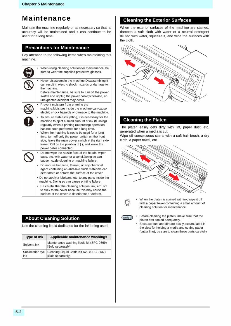
Chapter 5 Maintenance
5-2
MaintenanceMaintain the machine regularly or as necessary so that itsaccuracy will be maintained and it can continue to beused for a long time.
Precautions for Maintenance
Pay attention to the following items when maintaining thismachine.
About Cleaning Solution
Use the cleaning liquid dedicated for the ink being used.
Cleaning the Exterior Surfaces
When the exterior surfaces of the machine are stained,dampen a soft cloth with water or a neutral detergentdiluted with water, squeeze it, and wipe the surfaces withthe cloth.
Cleaning the Platen
The platen easily gets dirty with lint, paper dust, etc.generated when a media is cut.Wipe off conspicuous stains with a soft-hair brush, a drycloth, a paper towel, etc.
• When using cleaning solution for maintenance, be sure to wear the supplied protective glasses.
• Never disassemble the machine.Disassembling it can result in electric shock hazards or damage to the machine.Before maintenance, be sure to turn off the power switch and unplug the power cable;otherwise, an unexpected accident may occur.
• Prevent moisture from entering the machine.Moisture inside the machine can cause electric shock hazards or damage to the machine.
• To ensure stable ink jetting, it is necessary for the machine to eject a small amount of ink (flushing) regularly when a printing (outputting) operation has not been performed for a long time.
• When the machine is not to be used for a long time, turn off only the power switch on the front side, leave the main power switch at the right side turned ON (in the position of | ), and leave the power cable connected.
• Do not wipe the nozzle face of the heads, wiper, caps, etc. with water or alcohol.Doing so can cause nozzle clogging or machine failure.
• Do not use benzene, thinner, or any chemical agent containing an abrasive.Such materials can deteriorate or deform the surface of the cover.
• Do not apply a lubricant, etc. to any parts inside the machine. Doing so can cause printing failure.
• Be careful that the cleaning solution, ink, etc. not to stick to the cover because this may cause the surface of the cover to deteriorate or deform.
Type of Ink Applicable maintenance washings
Solventt inkMaintenance washing liquid kit (SPC-0369) [Sold separately]
Sublimation dye ink
Cleaning Liquid Bottle Kit A29 (SPC-0137) [Sold separately]
• When the platen is stained with ink, wipe it off with a paper towel containing a small amount of cleaning solution for maintenance.
• Before cleaning the platen, make sure that the platen has cooled adequately.
• Because dust and dirt are easily accumulated in the slots for holding a media and cutting paper (cutter line), be sure to clean these parts carefully.
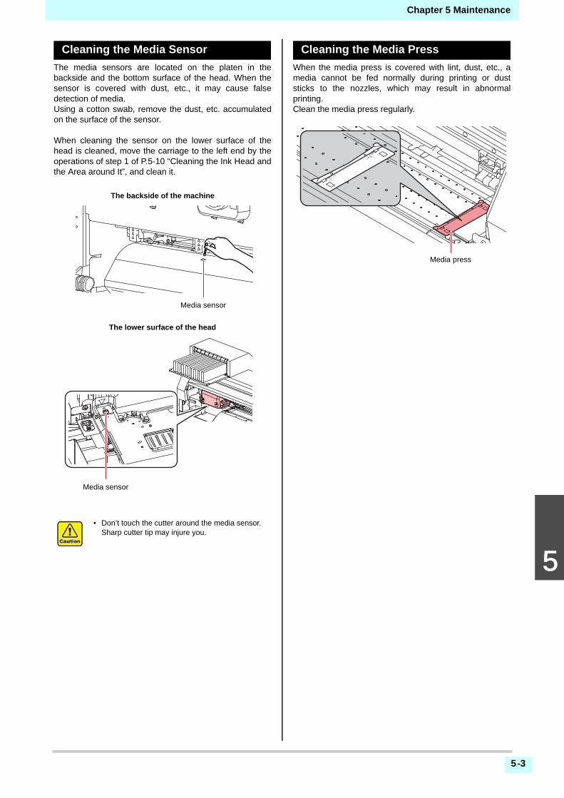
Chapter 5 Maintenance
5-3
5
2
Cleaning the Media Sensor
The media sensors are located on the platen in thebackside and the bottom surface of the head. When thesensor is covered with dust, etc., it may cause falsedetection of media.Using a cotton swab, remove the dust, etc. accumulatedon the surface of the sensor.
When cleaning the sensor on the lower surface of thehead is cleaned, move the carriage to the left end by theoperations of step 1 of P.5-10 “Cleaning the Ink Head andthe Area around It”, and clean it.
Cleaning the Media Press
When the media press is covered with lint, dust, etc., amedia cannot be fed normally during printing or duststicks to the nozzles, which may result in abnormalprinting.Clean the media press regularly.
• Don’t touch the cutter around the media sensor. Sharp cutter tip may injure you.
Media sensor
The backside of the machine
The lower surface of the head
Media sensor
Media press
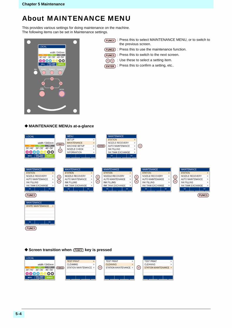
5-4
Chapter 5 Maintenance
About MAINTENANCE MENUThis provides various settings for doing maintenance on the machine.The following items can be set in Maintenance settings.
: Press this to select MAINTENANCE MENU, or to switch tothe previous screen.
: Press this to use the maintenance function.
: Press this to switch to the next screen.
: Use these to select a setting item.
: Press this to confirm a setting, etc..
MAINTENANCE MENUs at-a-glance
Screen transition when key is pressed

5-5
5
2
Chapter 5 Maintenance
MAINTENANCE MENUs at-a-glance
Item Set value Meaning
STATION MAINTENANCE
For carrying out maintenance on the carriage and station periphery.
CARRIAGE OUT( P.5-6)
Moves the carriage out, for carrying out cleaning of the cap periphery, head, wipers, etc.
NOZZLE WASH( P.5-7)
1 to 99minSoaks the nozzle surfaces in maintenance cleaning fluid, for carrying out recovery from nozzle clogging or bent.
DISWAY WASH( P.5-8)
Executes washing of the suction pump tubes.
CUSTODY WASH( P.5-8)
1 to 99minCarried out when the machine is going to be out of use for an extended period. Washes the nozzles and tubes beforehand, to keep the machine in fine condition.
WIPER EXCHANGE( P.5-15)
Used when replacing the wiper. If the wiper is replaced, the number of times the wiper was used that is managed in this device is reset.
NOZZLE RECOVERY( P.5-11)
For printing using another nozzle, if nozzle wash and so forth fail to effect recovery from nozzle clogging, etc.
PRINT Prints a pattern, to identify the nozzle that is clogged.
ENTRY Registers the faulty nozzle identified by “PRINT”.
RESET Resets a registered faulty nozzle.
AUTO MAINTENANCE( P.5-12)
For having the various maintenance functions executed automatically. Set the execution interval for each maintenance function.
REFRESH The set value will differ according to the ink type being used.
For setting the activation interval for refresh.
TUBE WASH For setting the activation interval for tube wash.
CLEANING For setting the activation interval for head cleaning.
CLEANING TYPENORMAL/ SOFT/ HARD
For setting the type of head cleaning.
INK FILLING( P.5-14)
Supplies ink to correct nozzle clogging.
INK TANK EXCHANGE( P.5-17)
Resets or corrects the used count for the waste ink tank.
WHITE/SILVER MAINT.( P.5-14)
Executes the white and silver ink maintenance.
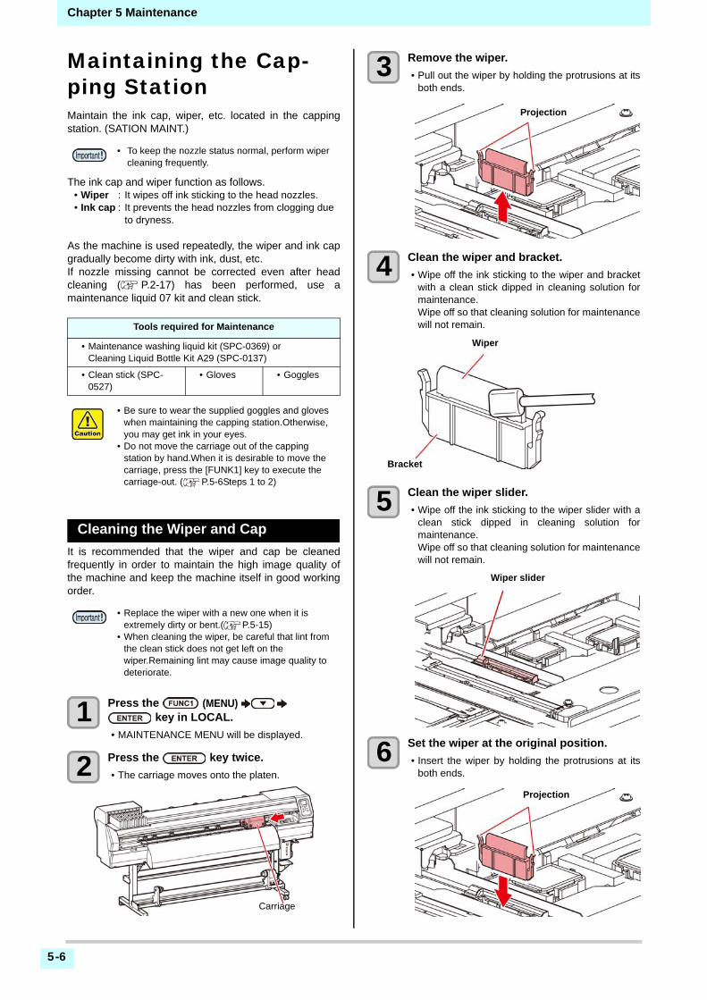
5-6
Chapter 5 Maintenance
Maintaining the Cap-ping StationMaintain the ink cap, wiper, etc. located in the cappingstation. (SATION MAINT.)
The ink cap and wiper function as follows.• Wiper : It wipes off ink sticking to the head nozzles.• Ink cap : It prevents the head nozzles from clogging due
to dryness.
As the machine is used repeatedly, the wiper and ink capgradually become dirty with ink, dust, etc.If nozzle missing cannot be corrected even after headcleaning ( P.2-17) has been performed, use amaintenance liquid 07 kit and clean stick.
Cleaning the Wiper and Cap
It is recommended that the wiper and cap be cleanedfrequently in order to maintain the high image quality ofthe machine and keep the machine itself in good workingorder.
1 Press the (MENU) key in LOCAL.
• MAINTENANCE MENU will be displayed.
2 Press the key twice.
• The carriage moves onto the platen.
3 Remove the wiper.
• Pull out the wiper by holding the protrusions at itsboth ends.
4 Clean the wiper and bracket.
• Wipe off the ink sticking to the wiper and bracketwith a clean stick dipped in cleaning solution formaintenance.Wipe off so that cleaning solution for maintenancewill not remain.
5 Clean the wiper slider.
• Wipe off the ink sticking to the wiper slider with aclean stick dipped in cleaning solution formaintenance.Wipe off so that cleaning solution for maintenancewill not remain.
6 Set the wiper at the original position.
• Insert the wiper by holding the protrusions at itsboth ends.
• To keep the nozzle status normal, perform wiper cleaning frequently.
Tools required for Maintenance
• Maintenance washing liquid kit (SPC-0369) or Cleaning Liquid Bottle Kit A29 (SPC-0137)
• Clean stick (SPC-0527)
• Gloves • Goggles
• Be sure to wear the supplied goggles and gloves when maintaining the capping station.Otherwise, you may get ink in your eyes.
• Do not move the carriage out of the capping station by hand.When it is desirable to move the carriage, press the [FUNK1] key to execute the carriage-out. ( P.5-6Steps 1 to 2)
• Replace the wiper with a new one when it is extremely dirty or bent.( P.5-15)
• When cleaning the wiper, be careful that lint from the clean stick does not get left on the wiper.Remaining lint may cause image quality to deteriorate.
Carriage
Projection
Wiper
Bracket
Wiper slider
Projection

5-7
5
2
Chapter 5 Maintenance
7 Clean the cap rubber.
• Wipe off the ink sticking to the cap rubber with aclean stick dipped in maintenance solution formaintenance.Wipe off so that maintenance solution formaintenance will not remain.
8 Press the key after the cleaning.
9 Close the front cover then press the key.
• After its initial operation, the machine returns tostep1.
Washing the Head Nozzle
1 Press the (MENU) key in LOCAL.
• MAINTENANCE MENU will be displayed.
2 Press to select the “STATION”, and press the key.
3 Press to select “NOZZLE WASH”, and press the key.
• The carriage will move onto the platen.
4 Clean the wiper and the bracket, and press the key.
(1) Open the right maintenance cover then pullout it by holding projections at both ends ofthe wiper.
(2) Clean the wiper and bracket with a clean stick dipped in maintenance washing liquid for maintenance. (SPC-0369: for solvent ink / SPC-0137: for sublimation dye ink)• Wipe off so that maintenance washing liquid
for maintenance will not remain.(3) Insert it in the original position by holding the
projections at both ends of the wiper.
5 Clean the cap rubber , and press the key.
• Wipe off the ink sticking to the cap rubber with aclean stick dipped in maintenance washing liquidfor maintenance.
• Wipe off so that maintenance washing liquid formaintenance will not remain.
• At this time, the discharge passage is cleanedautomatically.
6 Fill up the cap with cleaning solution for maintenance.
7 Close the front cover, and press the key.
Cap rubber
Carriage
Projection

5-8
Chapter 5 Maintenance
8 Press to set the time for the maintenance washing liquid to be left as it is, and press the key.
• Set value : 1 to 99 minutes (Unit: minute)• The maintenance washing liquid filled in the cap is
absorbed.• “Please Wait” will be displayed in the display until
the time you set has elapsed.
Washing the Ink Discharge Passage
Wash the ink discharge passage regularly(about once aweek) to prevent the head nozzles from clogging due toink coagulation inside the passage.
1 Press the (MENU) key in LOCAL.
• MAINTENANCE MENU will be displayed.
2 Press to select the “STATION”, and press the key.
3 Press to select “DISWAY WASH”, and press the key.
• The carriage will move onto the platen.• Dry suction operation is performed repeatedly
until the washing work is completed.
4 Press the key.
• Dry suction operation is performed repeatedlyuntil the washing work is completed.
5 Fill up the cap with cleaning solution for maintenance.
• If the cleaning solution cartridge is not usable,suck maintenance solution into a dropper and fillup the cap with it. Fill up the cap withmaintenance solution on the verge of overflowfrom the cap.
6 Press the key.
When the Machine Is Not Used for aLong Time
When the machine is not going to be used for a week ormore, use the cleaning function for custody to clean thehead nozzles and ink discharge passage.After this, keepthe machine in custody.
1 Press the (MENU) key in LOCAL.
• MAINTENANCE MENU will be displayed.
2 Press to select the “STATION”, and press the key.
• When nozzle missing is not cleared even after this washing is carried out several times, contact the distributor in your region or our service office.
• Before washing the ink discharge passage, make sure that the maintenance washing liquid is set. If the maintenance washing liquid is not set, washing operation will not be conducted and the passage could be clogged.
• Use the machine with always turning “ON” the main power. The function preventing nozzle clogging operates automatically to protect the head of the nozzle.
• The head nozzle may result in nozzle clogging if the main power switch is left OFF for a long time.
Check the items on the right beforehand.
Is [NEAR END] or [INK END] displayed?• The cleaning solution or ink is absorbed when the nozzles
are washed. At this time, if the state of "no ink" or "almost no ink" is detected, the nozzle washing operation cannot start.
• Replace the cartridge with another from which the state of "almost no ink" or "no ink" is not detected.
• When the worning messages “Check waste ink” are indicated, check the waste ink tank, and operate it, referring to P.5-15 “If a Waste Ink Tank Confirmation Message Appears” according to the situation.
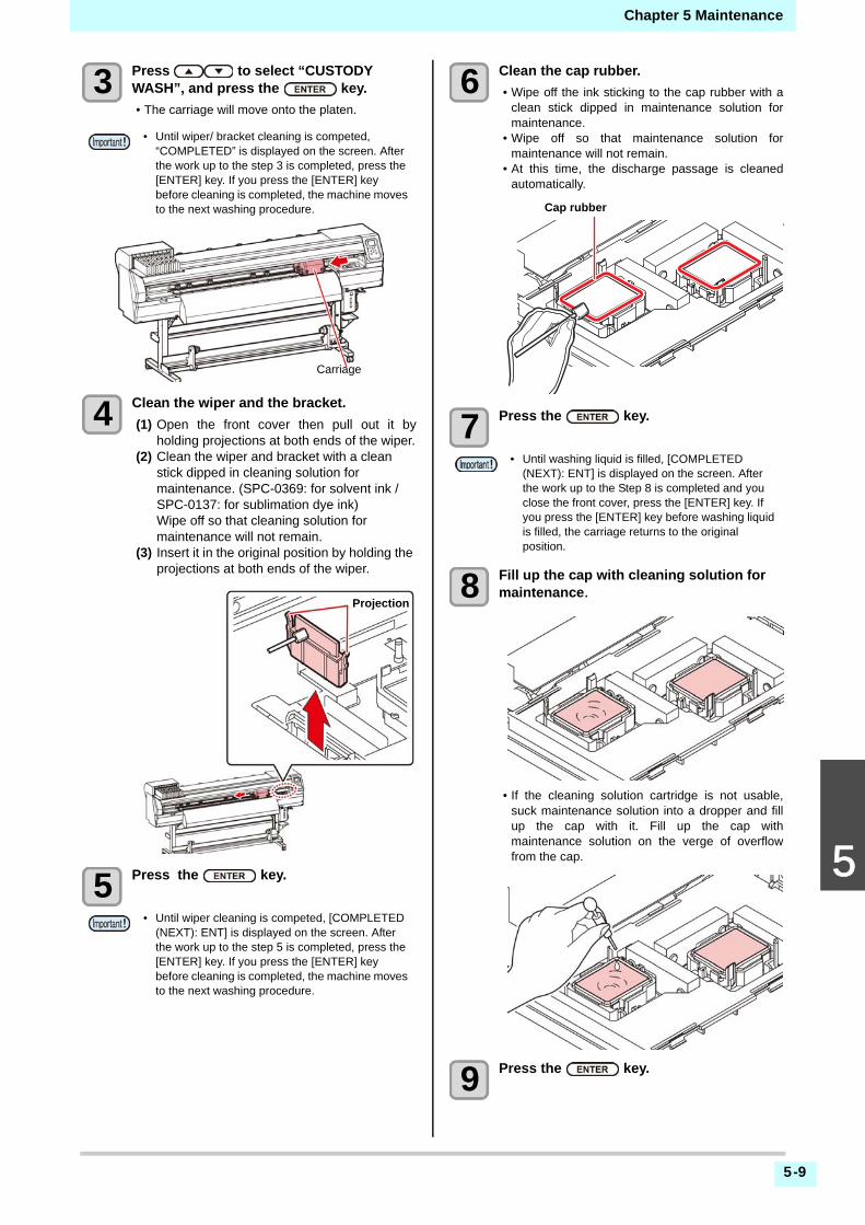
5-9
5
2
Chapter 5 Maintenance
3 Press to select “CUSTODY WASH”, and press the key.
• The carriage will move onto the platen.
4 Clean the wiper and the bracket.
(1) Open the front cover then pull out it byholding projections at both ends of the wiper.
(2) Clean the wiper and bracket with a clean stick dipped in cleaning solution for maintenance. (SPC-0369: for solvent ink / SPC-0137: for sublimation dye ink) Wipe off so that cleaning solution for maintenance will not remain.
(3) Insert it in the original position by holding the projections at both ends of the wiper.
5 Press the key.
6 Clean the cap rubber.
• Wipe off the ink sticking to the cap rubber with aclean stick dipped in maintenance solution formaintenance.
• Wipe off so that maintenance solution formaintenance will not remain.
• At this time, the discharge passage is cleanedautomatically.
7 Press the key.
8 Fill up the cap with cleaning solution for maintenance.
• If the cleaning solution cartridge is not usable,suck maintenance solution into a dropper and fillup the cap with it. Fill up the cap withmaintenance solution on the verge of overflowfrom the cap.
9 Press the key.
• Until wiper/ bracket cleaning is competed, “COMPLETED” is displayed on the screen. After the work up to the step 3 is completed, press the [ENTER] key. If you press the [ENTER] key before cleaning is completed, the machine moves to the next washing procedure.
• Until wiper cleaning is competed, [COMPLETED (NEXT): ENT] is displayed on the screen. After the work up to the step 5 is completed, press the [ENTER] key. If you press the [ENTER] key before cleaning is completed, the machine moves to the next washing procedure.
Carriage
Projection
• Until washing liquid is filled, [COMPLETED (NEXT): ENT] is displayed on the screen. After the work up to the Step 8 is completed and you close the front cover, press the [ENTER] key. If you press the [ENTER] key before washing liquid is filled, the carriage returns to the original position.
Cap rubber
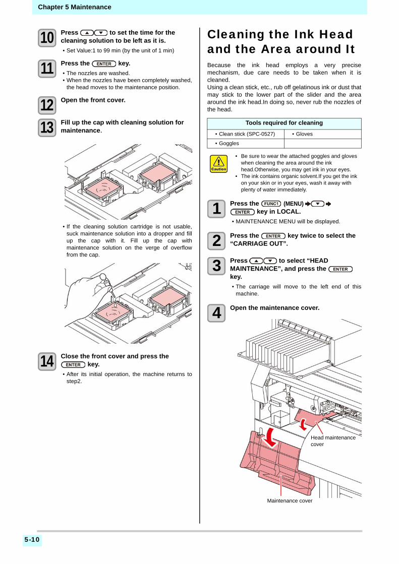
5-10
Chapter 5 Maintenance
10 Press to set the time for the cleaning solution to be left as it is.
• Set Value:1 to 99 min (by the unit of 1 min)
11 Press the key.
• The nozzles are washed.• When the nozzles have been completely washed,
the head moves to the maintenance position.
12 Open the front cover.
13 Fill up the cap with cleaning solution for maintenance.
• If the cleaning solution cartridge is not usable,suck maintenance solution into a dropper and fillup the cap with it. Fill up the cap withmaintenance solution on the verge of overflowfrom the cap.
14 Close the front cover and press the key.
• After its initial operation, the machine returns tostep2.
Cleaning the Ink Head and the Area around ItBecause the ink head employs a very precisemechanism, due care needs to be taken when it iscleaned.Using a clean stick, etc., rub off gelatinous ink or dust thatmay stick to the lower part of the slider and the areaaround the ink head.In doing so, never rub the nozzles ofthe head.
1 Press the (MENU) key in LOCAL.
• MAINTENANCE MENU will be displayed.
2 Press the key twice to select the “CARRIAGE OUT”.
3 Press to select “HEAD MAINTENANCE”, and press the key.
• The carriage will move to the left end of thismachine.
4 Open the maintenance cover.
Tools required for cleaning
• Clean stick (SPC-0527) • Gloves
• Goggles
• Be sure to wear the attached goggles and gloves when cleaning the area around the ink head.Otherwise, you may get ink in your eyes.
• The ink contains organic solvent.If you get the ink on your skin or in your eyes, wash it away with plenty of water immediately.
Head maintenance cover
Maintenance cover

5-11
5
2
Chapter 5 Maintenance
5 Use a clean stick soaked in maintenance cleaning fluid to wipe ink off the head surface or other surfaces.
• Never rub the nozzles.
6 Press the key after the cleaning.
7 Close the maintenance cover, and press the key.
• After its initial operation, the machine returns toLOCAL.
Nozzle Recovery FunctionNOZZLE RECOVERY: When nozzles missing can not beimproved at specific points, other good nozzles can beused as alternatives for printing.
1 Press the (MENU) key in LOCAL.
• MAINTENANCE MENU will be displayed.
2 Press to select “NOZZLE RECOVERY”, and press the key.
3 Press the key twice.
• Printing of the nozzle pattern will start.• Select “ENTRY” then “Move to select of the
Nozzle line (Step 4) without drawing a pattern”
4 Select the Nozzle line that needs NOZZLE RECOVERY by pressing , and press key.
Clean the side surface of the head (shown in deep gray) with a clean stick.
The nozzle part (Never touch it.)
Clean with a clean stick or a waste cloth.
110
2130
4150
6170
8190
101110
121130
141150
161170
181190
201210
221230
241250
261270
281290
301310
110
2130
4150
6170
8190
101110
121130
141150
161170
181190
201210
221230
241250
261270
281290
301310
110
2130
4150
6170
8190
101110
121130
141150
161170
181190
201210
221230
241250
261270
281290
301310
110
2130
4150
6170
8190
101110
121130
141150
161170
181190
201210
221230
241250
261270
281290
301310
110
2130
4150
6170
8190
101110
121130
141150
161170
181190
201210
221230
241250
261270
281290
301310
110
2130
4150
6170
8190
101110
121130
141150
161170
181190
201210
221230
241250
261270
281290
301310
110
2130
4150
6170
8190
101110
121130
141150
161170
181190
201210
221230
241250
261270
281290
301310
110
2130
4150
6170
8190
101110
121130
141150
161170
181190
201210
221230
241250
261270
281290
301310
Overhead view
H1-A H1-D H1-E H1-G
Nozzle line
H1-B H1-C H1-F H1-H
• For 6-color ink sets, the nozzle patterns “H1-B” and “H1-D” are not printed.
• When using leaf media, set a media of more than A3 size put horizontally. If a media with narrow width is set, printing will only be conducted to midway.
Nozzle pattern of Head 1
Head No.(H1 to H2)
Nozzle line

5-12
Chapter 5 Maintenance
5 Register the Nozzle number that needs NOZZLE RECOVERY and press key.
(1) Select the registration number from 1 to 10by pressing [][] key and press the[ENTER] key.
(2) Register the nozzle number that needs recovery by pressing [][] key and press the [ENTER] key.
6 Press the key several times to end the setting.
Reset the set value
1 Press the (MENU) key in LOCAL.
• MAINTENANCE MENU will be displayed.
2 Press to select “NOZZLE RECOVERY”, and press the key.
3 Press to select “RESET”, and press the key.
4 Press and (PAGE>) (<<) to selet theNozzle line that
need reset, and press the key.
• A reset confirmation message will be displayed.
5 Press the key.
6 Press the key several times to end the setting.
Automatic Mainte-nance FunctionTo use this machine comfortably, you can set variousmaintenances to be performed automatically.Here, set performing intervals of various automaticmaintenances.You can prevent troubles such as ink clogging byperforming automatic maintenance periodically (automaticmaintenance function).For the auto maintenance functions, the following itemscan be set:
• Up to 10 nozzles can be registered per 1 nozzle line.
• Even if you use this function, time required for drawing does not change.
• When printing has been done with the lowest path, nozzle recovery is not reflected.Moreover, depending on the conditions, there are cases where only 20 to 120 nozzles are enabled at both head ends (front and rear). Perform test printing to confirm.
• When you use white ink, print on the clear film to check.
Recovery nozzle No. or OFF
Registration number : 1 to 10
Nozzle missingNo.184
Nozzle number
Nozzle missing No.16
Nozzle missingNo.128
Registration number
Recovery Nozzle No.
State
1 16 Target for nozzle recovery
2 128 Target for nozzle recovery
3 184 Target for nozzle recovery
4 OFF No registration
5 OFF No registration
Example of nozzle to be recovered
• When you perform maintenance manually, after manual maintenance is completed and when time set with the automatic maintenance function has passed, maintenance starts automatically.
Function name Descriptions
REFRESHThe interval between each refreshing operation is set.
CLEANING (Interval)The interval between each cleaning operation is set.
CLEANING (Type) The cleaning type is set.
• If the “Check waste ink” warning message is displayed, the operation set in the auto maintenance function is not carried out. Perform the operations of P.5-16 “Replace the waste ink tank with another” if required.
• When the power switch on the front of the machine is turned off, check the waste ink tank.

5-13
5
2
Chapter 5 Maintenance
Setting the Refreshing Intervals
The interval between each operation of ejecting a smallamount of ink from the nozzles to prevent nozzle cloggingis set.
1 Press the (MENU) key in LOCAL.
• MAINTENANCE MENU will be displayed.
2 Press to select “AUTO MAINTENANCE”, and press the key.
3 Press to select the “REFRESH”, and press the key.
4 Press to set the refreshing interval, and press the key.
• Set value : The set value will differ according tothe ink type being used.
5 Press the key several times to end the setting.
Setting the Tube Wash Intervals
For setting the interval at which washing of the ink tubeswill be carried out, in order to prevent ink clogging due tocoagulation of ink inside the ink tubes.
1 Press the (MENU) key in LOCAL.
• MAINTENANCE MENU will be displayed.
2 Press to select “AUTO MAINTENANCE”, and press the key.
3 Press to select “TUBE WASH”, and press the key.
4 Press to set the tube washing interval, and press the key.
• Set value : The set value will differ according tothe ink type being used.
5 Press the key several times to end the setting.
Setting the Cleaning Intervals andType
The cleaning type and the interval between each cleaningoperation are set.
1 Press the (MENU) key in LOCAL.
• MAINTENANCE MENU will be displayed.
2 Press to select “AUTO MAINTENANCE”, and press the key.
3 Press the several times to select “Interval” or “Type”, and press the
key.
4 Press to select a set value, and press the key.
• Set value : The set value will differ according tothe ink type being used.
• Set value of type : SOFT/ NORMAL/ HARD
5 Press the key several times to end the setting.
• In order to perform tube washing with the Automatic Maintenance Function, the maintenance washing liquid needs to be set. If the maintenance washing liquid is not set, tube washing operation will not be regularly conducted and the passage could be clogged.

5-14
Chapter 5 Maintenance
Fill up InkSupplies ink to correct nozzle clogging.
1 Press the (MENU) key in LOCAL.
• MAINTENANCE MENU will be displayed.
2 Press to select “FILL UP INK”, and press the key.
3 Press to select the filling type.
• Soft : Use this in cases where head cleaningwill not achieve recovery, such as whenmultiple clogged nozzles occur ornozzle cluster dropout occurs.
• Normal : Use this if nozzle cluster dropout occursin initial ink filling.
• Hard : Use this in cases where the dumper hasbecome empty, such as in dumperreplacement.
4 Press the key.
• If you selected “Soft” in step 3, a Select Fill UpColor screen will be displayed.If you selected “Normal” or “Hard”, go to step 6.
5 Press to select the filling color, and press the key.
6 Press the key.
• Ink is supplied automatically.
7 Press the key several times to end the setting.
White Ink MaintenanceWhite ink precipitates easier than other inks.
• If not printing more than two weeks, white ink may precipi-tate in the ink cartridge or inside of this machine.
• When an ink precipitates, the nozzle may be clogged and it can not draw normally.
• Make sure to perform periodical maintenance to avoid pre-cipitation and to keep white ink in good condition.
1 Press the (MENU) key in LOCAL.
• MAINTENANCE MENU will be displayed.
2 Press (<<) , and press the key.
3 Press to select “WHITE MAINT”, and press the key.
4 Press the key.
5 Press the key.
• The automatic discharging operation and thefilling operation are performed, then, cleaning isperformed.
6 Press the key several times to end the setting.
• Perform the maintenance below before working once a week.
• Use the specified ink cartridge.
As the component of white ink is easy to settle out, it is necessary to shake it periodically.• When 24 hours have passed with the power
supply is ON.• When the power supply is ON, the warning
message “SHAKE WHITE INK CARTRIDGES” is displayed.

5-15
5
2
Chapter 5 Maintenance
Replacing consumables
Replacing the wiper
The wiper is consumable. When the display indicates thewarning message “Replace a WIPER” it is necessary tocheck and replace the wiper, immediately replace thewiper with a new one.Also, wipe ink sticking to the lower surface of the slider off.
1 Press the (MENU) key in LOCAL.
• MAINTENANCE MENU will be displayed.
2 Press to select the “STATION”, and press the key.
3 Press to select “WIPER EXCHANGE”, and press the key.
• The number of times the wiper was used will bereset.
4 Press the key.
• The carriage will move onto the platen.
• The number of times the wiper was used will bereset.
5 Remove the wiper.
• Pull out the wiper by holding the protrusions at itsboth ends.
6 Insert a new wiper.
• Insert the wiper by holding the protrusions at itsboth ends.
7 Press the key.
• After its initial operation, the machine returns toLOCAL.
If a Waste Ink Tank Confirmation Message Appears
Ink used in head cleaning, etc. is stored in the waste inktank on the lower right side of the machine.This machinecounts the accumulated amount of discharged ink. Whenthat reaches a specified amount, the machine displays aconfirmation message.(When this message is displayed,consider the replacement of the waste ink tank.)
Confirmation Message in LOCAL
1 The warning message “Check waste ink” is displayed.
2 Check the state of the waste ink tank
• When it is different from the actual amount, press[][] and correct.
• When you correct (80%), press the [ENTER] keyto return to LOCAL.
• When you replace (disposal) and clear the count,perform the procedures in “Replace the waste inktank with another”. ( P.5-16)
• When the warning message for replacing wiper is shown, confirm whether there is no damage and fuzz at the top edge of the wiper film. If there is no damage on the top edge of the wiper film, it is possible to use the wiper continuously without replacing it.
• A cleaning wiper is an option.Buy one through the dealer in your region or at our service office.
Carriage
Projection
• The message is displayed when it reaches 80% (1.6L ) of the 2L tank.
Projection

5-16
Chapter 5 Maintenance
Replace the waste ink tank with another
1 The warning message “Check waste ink” is displayed.
2 Press the (MAINT.) key.
3 Check the state of the waste ink tank.
4 If the amount of waste ink needs to be adjusted, press the key.
• Compare the amount of waste ink shown on thedisplay and the amount you visually confirmed. Ifthere is no major problem with the value shownon the display, instead of the [ENTER] key, pressthe [END] key and proceed to Step 6.
5 Press to adjust the level, and press the key.
6 Pull the waste ink tank stopper to open to the front.
7 Pull it frontward to remove by holding the waste ink tank handle.
8 Replace the waste ink tank.
(1) Prepare a new waste ink tank (SPC-0117).(2) Insert the waste ink tank by holding a handle
of the tank.
9 Close the waste ink tank stopper.
10 Press the key.
• The ink discharging amount that is controlled bythe machine is reset and the message iscancelled.
• Put a cap on the waste ink tank removed.
Waste ink tank stopper
Waste ink tank
Cap
• Waste ink is equivalent to waste oil of industrial waste. Request an industrial waste disposal company for disposal of waste ink.
New waste ink tank

5-17
5
2
Chapter 5 Maintenance
Replacing the waste ink tank before the wasteink tank confirmation message is displayed
if you replace the waste ink tank before the waste ink tankconfirmation message is displayed (before the 2L tank is80% (1.6L) full), set the waste ink information to 0% in theInformation menu.
1 Perform steps 6 through 9 in "Replace the waste ink tank with another" ( P.5-16) to empty the waste ink tank.
2 Press the (MENU) key in LOCAL.
• MAINTENANCE MENU will be displayed.
3 Press to select “INK TANK EXGHANGE”, and press the key.
4 Waste ink tank information is displayed.
5 Press the (v) .
• The reset screen for the waste ink tank amountwill be displayed.
6 Press the key.
• The waste ink tank amount that is managed in thismachine will be reset.
Replacing the Cutter Blade
The media cutter blade is consumable. When the cutterblade gets dull, replace it with a new one (SPA-0107).
1 Press the (MENU) key in LOCAL.
• MAINTENANCE MENU will be displayed.
2 Press the key twice.
• The carriage moves onto the platen.
3 Replace the cutter unit by the carriage.
• Now the cutter unit can be moved manually. Movethe cutter unit to the position where you canassure easy access, and replace the blade edge.
(1) Loosen the screw of the cutter unit.(2) Remove the cutter unit.(3) Mount a new cutter unit.(4) Fasten the screw of the cutter unit to secure
the cutter unit.
4 When replacement is finished, press the key.
• The screen returns to LOCAL.
• The blade is sharp. Be careful not to hurt yourself or anyone else.
• Store the cutter blade in a place that is out of the reach of children. In addition, dispose of used cutter blades according to regional laws and regulations.
• When replacing the cutter blade, it is recommended to place a sheet of paper under the cutter blade. This will help pick up the cutter blade if it drops.
Carriage
Screw
Cutter unit

5-18
Chapter 5 Maintenance
Replacing and Adjust-ing the Cutter Blade
Replacing the cutter
If the cutter is chipped or blunt, replace it with a new one.(Accessorry parts number: SPA-0030) New cutter (low-pressure blade set for PVC sheets: ModelSPB-0030) are available from your distributor or MIMAKI'ssales office.
1 Remove the cap located at the edge by rotating it.
2 Replace the cutter with a new one using tweezers or the like.
Adjusting the Cutter Blade
After adjusting the blade edge, set the cut condition andperform test cut to check whether cutting is performedwell.
1 Turn the adjusting knob to adjust the protruding amount of the cutter.
• arrow to protrude the cutter blade. ( 0.5 mm per revolution)
Replacing the cutter other than sup-plied one
1 Loosen the lock nut, and pull the adjusting knob out of the holder.
2 Insert the cutter into the adjusting knob using tweezers.
3 Tighten the lock nut.
• The cutter blade is sharp. Keep your fingers away from the cutter.
• Do not shake or swing the cutter holder; otherwise, the cutter blade may come off, which is dangerous.
• Keep the cutter out of reach of children. Dispose of the used cutter blade in compliance with the applicable regulations.
Name of productProduct
No.Specifications
Remarks
Decentering blade for vinyl sheet
SPB-0001Three blades
Decentering blade for small letters
SPB-0003Three blades
Decentering blade for rubber sheet
SPB-0005Three blades
Decentering blade for reflecting sheet
SPB-0006Two blades
Decentering blade for fluorescent sheet
SPB-0007Three blades
Replacing the cutter other than supplied one
SPB-0030Three blades
supplied one
Decentering blade for thick rubber sheet
SPB-0084Three blades
Cutter hoider
Cutter
Cap
Cutter
Adjusting knob
Lock nut
Adjusting knob

5-19
5
2
Chapter 5 Maintenance
Adjusting blade edge of cutter otherthan supplied one
1 Loosen the lock nut.
2 Turn the adjusting knob to adjust the protruding amount of the cutter blade.
3 Tighten the lock nut so that the adjusting knob will not turn.
• The blade adjuster (Product No.: OPT-S1005) will facilitate the adjustment of the protruding amount of the blade.
Lock nut
Adjusting knob

5-20
Chapter 5 Maintenance

This chapter
describes the corrective measures to be taken for a phenomenon suspected to be trou-ble and the procedures to clear the error number displayed on the LCD.
Troubleshooting ...............................................................................6-2Power does not turn on ................................................................... 6-2The machine does not start printing ................................................ 6-2Media get jammed / media is soiled ................................................ 6-2The heater’s temperature will not rise to the set level ..................... 6-3Image quality is poor ....................................................................... 6-3Nozzle is clogged ............................................................................ 6-3Ink cartridge warning appears ......................................................... 6-4When the ink leakage occurs ..........................................................6-4
Warning / Error Messages ...............................................................6-5Warning messages.......................................................................... 6-5Error messages ............................................................................... 6-8
Chapter 6
Troubleshooting

Chapter 6 Troubleshooting
6-2
TroubleshootingTake appropriate actions as described below before taking the trouble as a failure.If still the problem is not solved after troubleshooting, contact your dealer or an office of MIMAKI.
Power does not turn on
In most cases, this is due to improper connection of the power cable for the machine or computer. Check that the powercable is connected properly.
The machine does not start printing
This occurs when the data is not being transmitted to the machine properly.It can also occur when the printing function does not work properly or the media is not set correctly.
Media get jammed / media is soiled
Media jamming or stained media is considered to be due to the use of an unsuitable media or improper setting of media.
Has the power cable been connected between the machine and a power plug socket ?
Securely connect the power cable.
Is the main switch ON ? Turn on the main switch. ( P.2-3)
Is the power switch located on the front of machine "ON" ?
Turn on the power switch on the front of the machine.
Is the correct interface cable used ? Use the cable exclusive for the device.
Is the interface cable properly connected ? Securely connect the interface cable.
Yes
Is the message on the display indicating that ink has run out ?
Replace the ink cartridge with a new one.
Is a recommended media used ? Use recommended media.
Is the media not curled or bent ends ? Avoid using any media with curls or bent ends.
Yes
Is the media hanging down along the platen ?
Use a take-up device or rRe-load the media on the machine. ( P.2-10 , P.2-4)
No
No
No
No
No
Yes
No
No
No

Chapter 6 Troubleshooting
6-3
1
2
2
2
2
6
The heater’s temperature will not rise to the set level
Check the basic operation.
Image quality is poor
This section describes the corrective actions to be taken in case the image quality is not satisfactory.Take remedy for particular problems with image quality. If the remedy does not work, contact your dealer or an office ofMIMAKI.
Nozzle is clogged
When nozzle clogging is not dissolved even after the head cleaning referring to P.2-17, make sure the followingoperations.
Wash the head nozzle by the operations of P.5-7.
Wash the head nozzle surface by the operations of P.5-10.
Recovery the nozzle by the operations of P.5-11.
Is the power to the machine ON ? Turn on the power to the machine. ( P.2-3)
Yes
Is the heater temperature setting effective ? Set the heater temperature. ( P.3-6)
Phenomenon Measures
White lines / blur / dark stripes (in the direction of travel of the heads)
(1) Execute the head cleaning. ( P.2-17)(2) Perform maintenance of the inside of the station. ( P.5-6)(3) Execute the [FEED COMP.] function. ( P.3-5)(4) If any pieces of paper or dust is attached on the path of the heads such as
media press, remove it.
Characters are double- or triple-printed in the media feed direction
(1) Execute the [FEED COMP.] function. ( P.3-5)
Disagreement in print positions between outward trip and homeward trip
(1) Execute the [DROP POSITION] function. ( P.3-6)
Ink drops falling on media during printing
(1) Execute the wiper cleaning. ( P.5-6)(2) Execute the ink cap cleaning. ( P.5-6)(3) Clean around the head. ( P.5-10)(4) Execute the head cleaning [NORMAL]. ( P.2-17)(5) Set the INTERVAL WIPING operation. ( P.3-9)
No
No

Chapter 6 Troubleshooting
6-4
Ink cartridge warning appears
If an ink cartridge trouble is detected, the cartridge LED “red” is lit, and a warning message appears.None of printing, cleaning and all the other operations that use ink is available.In this case, replace the ink cartridge in question immediately.
Displaying the description of ink cartridge trouble
The contents of cartridge error are confirmable by the following operations.
1 Press the key in LOCAL.
2 Press the key.
When the ink leakage occurs
If the ink leakage occurs, unplug the power plug to turn off the main power switch, and contact our service office ordistributor.
• Once cartridge trouble is displayed, do not leave the ink cartridge without replacing it for a long time; otherwise, the machine will lose the nozzle clogging prevention function.If nozzles are clogged, the machine must be repaired by MIMAKI's service engineer.

Chapter 6 Troubleshooting
6-5
1
2
2
2
2
6
Warning / Error MessagesIf some trouble occurs, the buzzer sounds and the display shows a corresponding error message.Take an appropriate remedy for the displayed error.
Warning messages
Errors when performing operations
Message displayed in LOCAL
Message Cause Solution
Operation cannot be performed because no media is detected.
• Execute after media is detected.
The motor is OFF after the cover was opened etc.
• Return to LOCAL and execute the operationafter completion of initialization.
An ink error occurred.• Execute the operation after replacing with a
new ink cartridge.
The front cover or the maintenance cover is opened.
• Execute the operation after closing thecover.
Data was received.• Execute the operation after executing data
clear.( P.2-19)
Message Cause Solution
Multiple ink errors (unusable ink) have occurred, making it impossible to feed ink (printing and cleaning, etc.).
Replace with a new ink cartridge.
The waste ink tank count has exceeded the prescribed amount.
Check the amount of waste ink in the waste ink tank.Conduct maintenance and waste ink tank replacement, and reset the amount of waste ink.
The used count of wiper has exceeded the prescribed number.
Execute maintenance, station maintenance and wiper exchange and replace the wiper.
Displayed when power is forcibly turned OFF and restarted after occurrence of “ERROR 710 heater temp error”.
If the same error message appears again, contact our service desk or your local distribu-tor to call for service.
No media is set. Or, the sensor is faulty.
Set the media.If the same error message still appears after setting the media, contact our service desk or your local distributor to call for service.
Print data is received in LOCAL.Shift to REMOTE and execute printing.Or, execute data clear and cancel printing.
Stable printing cannot be done because temperature in the installed environment (machine) is too high. Adjust the ambient temperature to within the
specified scope (20°C to 35°C).Stable printing cannot be done because temperature in the installed environment (machine) is too low.
INVAILD OPERATION:MEDIA UNDETECT
INVAILD OPERATION:MOTOR POWER OFF
INVAILD OPERATIONINK ERROR
INVAILD OPERATIONCOVER OPEN
INVAILD OPERATIONDATA REMAIN
Can't print/cartridge
Check waste ink
Replace WIPER
HEATER Temp. errorPowered off
NO MEDIA
DATA REMAIN
MACHINE TEMP./H **°C
MACHINE TEMP./L **°C
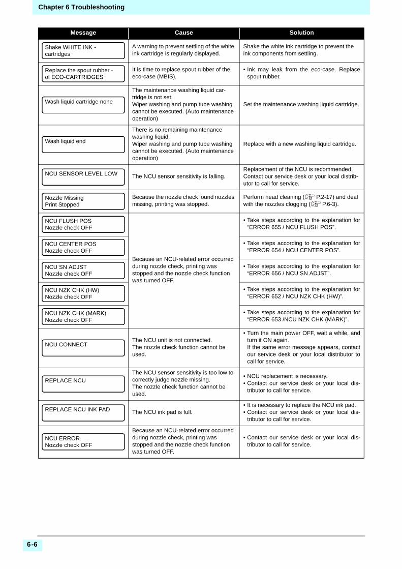
Chapter 6 Troubleshooting
6-6
A warning to prevent settling of the white ink cartridge is regularly displayed.
Shake the white ink cartridge to prevent the ink components from settling.
It is time to replace spout rubber of the eco-case (MBIS).
• Ink may leak from the eco-case. Replacespout rubber.
The maintenance washing liquid car-tridge is not set.Wiper washing and pump tube washing cannot be executed. (Auto maintenance operation)
Set the maintenance washing liquid cartridge.
There is no remaining maintenance washing liquid.Wiper washing and pump tube washing cannot be executed. (Auto maintenance operation)
Replace with a new washing liquid cartridge.
The NCU sensor sensitivity is falling.Replacement of the NCU is recommended.Contact our service desk or your local distrib-utor to call for service.
Because the nozzle check found nozzles missing, printing was stopped.
Perform head cleaning ( P.2-17) and deal with the nozzles clogging ( P.6-3).
Because an NCU-related error occurred during nozzle check, printing was stopped and the nozzle check function was turned OFF.
• Take steps according to the explanation for“ERROR 655 / NCU FLUSH POS”.
• Take steps according to the explanation for“ERROR 654 / NCU CENTER POS”.
• Take steps according to the explanation for“ERROR 656 / NCU SN ADJST”.
• Take steps according to the explanation for“ERROR 652 / NCU NZK CHK (HW)”.
• Take steps according to the explanation for“ERROR 653 /NCU NZK CHK (MARK)”.
The NCU unit is not connected.The nozzle check function cannot be used.
• Turn the main power OFF, wait a while, andturn it ON again.If the same error message appears, contactour service desk or your local distributor tocall for service.
The NCU sensor sensitivity is too low to correctly judge nozzle missing.The nozzle check function cannot be used.
• NCU replacement is necessary.• Contact our service desk or your local dis-
tributor to call for service.
The NCU ink pad is full.• It is necessary to replace the NCU ink pad.• Contact our service desk or your local dis-
tributor to call for service.
Because an NCU-related error occurred during nozzle check, printing was stopped and the nozzle check function was turned OFF.
• Contact our service desk or your local dis-tributor to call for service.
Message Cause Solution
Shake WHITE INK -cartridges
Replace the spout rubber -of ECO-CARTRIDGES
Wash liquid cartridge none
Wash liquid end
NCU SENSOR LEVEL LOW
Nozzle MissingPrint Stopped
NCU FLUSH POSNozzle check OFF
NCU CENTER POSNozzle check OFF
NCU SN ADJSTNozzle check OFF
NCU NZK CHK (HW)Nozzle check OFF
NCU NZK CHK (MARK)Nozzle check OFF
NCU CONNECT
REPLACE NCU
REPLACE NCU INK PAD
NCU ERRORNozzle check OFF

Chapter 6 Troubleshooting
6-7
1
2
2
2
2
6
Ink Error
Ink error is displayed also in the local guidance. ( P.3-25)
Message Cause Solution
The IC chip of the ink cartridge cannot be read normally.
• Remove the cartridge generating the warn-ing once and install it again.
• If the same warning message still appears,contact your local distributor to call for ser-vice.
The ink of the ink cartridge is different in type from the ink currently supplied.
• Check the ink type of the cartridge generat-ing the warning.
The ink of the ink cartridge is different in color from the ink currently supplied.
• Check the ink color of the cartridge generat-ing the warning.
An error occurred in the IC chip informa-tion of the ink cartridge.
• Check the cartridge generating the warn-ing.Make sure there is no nozzle clogging
An ink cartridge has not been installed in the slot.
• Install an appropriate cartridge in the slotgenerating the warning.
The ink of the ink cartridge has been completely used up.
• Replace the cartridge generating the warn-ing with a new one.
There is only a little bit of ink left in the ink cartridge.
• The ink will soon be used up.Be careful.
The ink of the ink cartridge has been nearly used up.
• Replace the cartridge generating the warn-ing with a new one.However, it can be used until the month afternext.
The specified expiration date of an ink cartridge has passed. (one month has passed after the specified expiration date).
• The expiration date has passed.However, you can use it until the end of thefollowing month.
The expiration date of an ink cartridge has passed (two months have passed after the specified expiration date).
• More than two months have passes after theexpiration date. Replace the cartridge gener-ating the warning with a new one.
The ink remaining has become 0. (Only when ink end / 4 color ink set)
• Replace the cartridge with a new one.
WRONG INK IC
INK TYPE
INK COLOR
WRONG CARTRIDGE
NO CARTRIDGE
INK END
INK NEAR END
Expiration
Expiration:1MONTH
Expiration:2MONTH
ERROR 63cINK REMAIN ZERO

Chapter 6 Troubleshooting
6-8
Error messages
When an error message is displayed, eliminate the error according to the chart below.If the same error message appears again, contact your dealer or an office of MIMAKI to call for service.
Message Cause Solution
SDRAM is defective.
• Turn off the power to the machine and turn iton after a while.
• If the same error message appears again,contact your local distributor to call for ser-vice.Head control circuit board is defective.
The battery life end of the internal clock is detected.
• Contact your local distributor to call for ser-vice.
Head data transferring sequence error occurred.
• Turn off the power to the machine and turn iton after a while.
• If the same error message appears again,contact your local distributor to call for ser-vice.
Sequential number abnormality of the event log occurred.
An error occurred in the main PCB .
COM driver becomes the high tempera-ture.
New Print Head was recognized.
An error is detected on the waveform printed on.
An error occurred in the main PCB .
ERROR 122CHECK:SDRAM
ERROR 128HDC FIFO OVER
ERROR 128HDC FIFO UNDER
ERROR 129BATTERY EXCHANGE
ERROR 130HD DATA SEQ
ERROR 146E-LOG SEQ
ERROR 151Main PCB V1R2
ERROR 152Main PCB V2R5
ERROR 153Main PCB V3R3
ERROR 154Main PCB V05
ERROR 157Main PCB VTT
ERROR 16eMain PCB V3R3B
ERROR 15fHEAD DRIVE HOT
ERROR 171NEW HEAD CONNECT
ERROR 186HDC OVERFLOW
ERROR 186HDC UNDERFLOW
ERROR 187HDC SLEW RATE
ERROR 188HDC MEMORY
ERROR 18aMain PCB V_CORE

Chapter 6 Troubleshooting
6-9
1
2
2
2
2
6
An error occurred in the main PCB .
• Turn off the power to the machine and turn iton after a while.
• If the same error message appears again,contact your local distributor to call for ser-vice.
An error occurred in the COM16/32IO PCB .
An error occurred in the SLIDER2H PCB .
The machine received some data other than print data.Or, an error occurred in the transmitted print data.
• Securely connect the interface cable in posi-tion.
• Use an interface cable conforming to thespecifications.An error occurred in the transmitted print
data.
An error occurred in the communication of USB.
• Turn off the main power to the machine andturn it on after a while.
• If the same error message appears again,contact your local distributor to call for ser-vice.
An excessive load was applied to the X motor.
An excessive load was applied to the Y motor.
An error due to an excessive current of the X motor was detected.
• Turn off the main power to the machine andturn it on after a while.
• If the same error message appears again,contact your local distributor to call for ser-vice.
An error due to an excessive current of the Y motor was detected.
Roller sensor abnormality• The roller sensor cannot be correctly
read.
• Confirm that the winding unit of machine set-ting and tension bar setting are ON.
• Check the set state of the media.• Confirm that the winding unit operates using
the manual SW.
Message Cause Solution
ERROR 18cMain PCB V12
ERROR 190Main PCB V42-1
ERROR 192COMIO PCB V1R2
ERROR 193COMIO PCB V2R5
ERROR 194COMIO PCB V3R3
ERROR 195COMIO PCB V24
ERROR 1a0SLDR2H PCB V1R2
ERROR 1a6SLDR2H PCB V2R5
ERROR 1a7SLDR2H PCB V3R3
ERROR 1a8SLDR2H PCB V5
ERROR 1a9SLDR2H PCB V42
ERROR 201COMMAND ERROR
ERROR 202PARAMETER ERROR
ERROR 304USB INIT ERR
ERROR 305USB TIME OUT
ERROR 401MOTOR X
ERROR 402MOTOR Y
ERROR 403X CURRENT
ERROR 404Y CURRENT
ERROR 44fTake-UP Roll Sns Err

Chapter 6 Troubleshooting
6-10
Could not separate the print head.
• Turn off the main power to the machine andturn it on after a while.If the same error message appears again,contact your local distributor to call for ser-vice.
Could not connect to the print head.
Could not separate the cutter head.
Could not connect to the cutter head.
The pinch roller position is not appropri-ate.
• Place the pinch roller above the grid roller.If the same error message appears again,contact your local distributor to call for ser-vice.
The media jam occurs. • Remove the media and reset it.
An error occurred in the control position.
• Turn off the main power to the machine andturn it on after a while.If the same error message appears again,contact your local distributor to call for ser-vice.
Y-origin could not be detected.
Abnormal linear scale.
The media width could not be correctly read.
• Check the media set position. ( P.2-4)• Clean the media sensor. ( P.5-3)• Turn the main power OFF, wait a while, and
turn it ON again.
The media is set outside the proper area.
• Check the media set position. ( P.2-9)
Pump sensor detection error
• Turn the main power OFF, wait a while, andturn it ON again.If the same error messageappears, contact our service desk or yourlocal distributor to call for service.
Ink end (cannot be used, can only be used when cleaning with the 4-color ink set)
• Replace with new ink.
The ink cartridge IC chip cannot be cor-rectly read.
• Make sure that the cartridge is correctlyinserted.
• Reinsert the cartridge.• Turn the main power OFF, wait a while, and
turn it ON again.If the same error messageappears, contact our service desk or yourlocal distributor to call for service.
There is a slot in which the cartridge has not been inserted more than a certain time.
• Set a cartridge.
A problem has occurred in the ink car-tridge IC chip information.The used count has exceeded the pre-scribed value.
• Make sure there is no nozzle clogging(especially for the white ink).
Message Cause Solution
ERROR 45aP-HEAD TAKE OFF Err
ERROR 45bP-HEAD CONNECT Err
ERROR 45cC-HEAD TAKE OFF Err
ERROR 45dC-HEAD CONNECT Err
ERROR 45eCHECK PR/GR POSITION
ERROR 505MEDIA JAM
ERROR 509HDC POSCNT
ERROR 50aY ORIGIN
ERROR 50fL-SCALE BLACK
ERROR 529LEnc.Count HPC[____]
ERROR 52aLEnc.Count HDC[____]
ERROR 52cMEDIA WIDTH SENSOR
ERROR 516MEDIA SET POSITION R
ERROR 528PUMP MOTOR SENSOR
ERROR 602CARTRIDGE END
ERROR 608WRONG INK IC
ERROR 627RE-INSERT CARTRIDGE
ERROR 628WRONG INK CARTRIDGE

Chapter 6 Troubleshooting
6-11
1
2
2
2
2
6
Remaining ink is 0 in the cartridge (ink end/ only when the 4-color ink set is used).
• Replace with new ink.
The nozzle check has been suspended due to some problem.
• Turn the main power OFF, wait a while, andturn it ON again.If the same error message appears, contactour service desk or your local distributor tocall for service.
The NCU unit is not connected.
The NCU sensor sensitivity is too low to correctly judge nozzle missing.The nozzle check function cannot be used.
The NCU cannot correctly recognize the ink discharge, because there are fre-quent nozzle missing and ink droplet misalignment.
• Check the state of the nozzles, and if thereare frequent nozzle missing and ink dropletmisalignment, conduct cleaning to restore.
Adjustment of the discharge position to the NCU has failed.
Sensor sensitivity adjustment has failed.
• Check the state of the nozzles, and if thereare frequent nozzle missing and ink dropletmisalignment, conduct cleaning to restore.
• If the same error message still appears afterrestoring the state of the nozzles, contactour service desk or your local distributor tocall for service.
The NCU ink pat is full.• Contact our service desk or your local dis-
tributor to call for service.
The NCU sensor sensitivity is falling.• Replacement of the NCU is recommended.
Contact our service desk or your local dis-tributor to call for service.
The thermistor connection of a heater is defective.
• Check the thermistor connection of the dry-ing heater.
• Turn off the main power to the machine andturn it on after a while.
• If the same error message appears again,contact your local distributor to call for ser-vice.
The temperature abnormality of the heater has been detected.When this error occurred and if the tem-perature abnormality cannot be resolved, the power supply of the machine is forcibly turned off.
• Turn off the main power to the machine andturn it on after a while.
• If the same error message appears again,contact your local distributor to call for ser-vice.
Due to a certain error, the function can-not be performed.
• Return to the local screen, check the errorstatus and take a countermeasure.
There remains received data that has not yet been printed.
• Execute the data clear function. ( P.2-27)
An error occurred in the mounted heads.
• Turn off the main power to the machine andturn it on after a while.
• If the same error message appears again,contact your local distributor to call for ser-vice.
Message Cause Solution
ERROR 63cINK REMAIN ZERO
ERROR 64CNCU ERROR
ERROR 650NCU CONECT
ERROR 651REPLACE NCU
ERROR 652NCU NZK CHK (HW)
ERROR 653NCU NZK CHK (MARK)
ERROR 654NCU CENTER POS
ERROR 655NCU FLUSH POS
ERROR 656NCU SN ADJST
ERROR 657REPLACE NCU INK PAD
ERROR 6558NCU SENSOR LV LOW
ERROR 702THERMISTOR CONNECT
ERROR 710HEATER TEMP ERROR
ERROR 901INVAILD OPERATION
ERROR 902DATA REMAIN
ERROR 90dNO HEAD SELECT

Chapter 6 Troubleshooting
6-12
The media width or the media length required for printing is not enough.
• Change the media to the one with enoughwidth or length.
• When the media width narrows because theorigin moved, slide the origin to the right towiden the effective media width.
An error occurred in the main PCB FROM.
• Turn off the main power to the machine andturn it on after a while.
• If the same error message appears again,contact your local distributor to call for ser-vice.
Received the code other than the com-mand date.
• Check the USB cable connection. Use theUSB cable that complies with the specifica-tions. Use the MIMAKI driver that matchesthe device.
• Turn off the printer, wait for a while, and turnon the printer again. If the same error mes-sage appears again, contact your local dis-tributor to call for service.
Received the parameters outside the value range.
Received the invalid device control com-mand.
You have performed "Copy", but the data is not stored in the reception buffer.
• Execute Copy function using the same dataone more time.
The received data is too big to multiple sheet cutting.
• The received data is too big to cut it inpieces.
The feeding direction of the sheet is too short.
• Use a longer sheet.
Could not detect the registration marks.
Check whether the registration marks are placed appropriately. ( P.4-2)Make sure that the media is not curled.Make sure that the position to start detecting the registration marks is correct.Make sure that black registration marks are printed on a white base.Make sure that there are no printed images or smudges between registration marks and that there is no dust adhered.Make sure that the registration mark detection settings are correct.If the registration marks still cannot be detected, even after clearing the check items above, contact our service desk or your local distributor to call for service.If the area around registration marks are col-ored, set the “MARK FILL UP” of the registra-tion mark detection settings to ON.
The registration mark detection result shows that the origin position was detected outside the print range.
• Place the registration marks within thesheet.
Message Cause Solution
ERROR 90fPRINT AREA SHORT
ERROR 04PARAM ROM
ERROR C10COMMAND
ERROR C11PARAMETER
ERROR C12DEVICE
ERROR C31NO DATA
ERROR C32DATAtooBIG
ERROR C33SHEET SIZE
ERROR C36MARKdetect
ERROR C37MARK ORG

Chapter 6 Troubleshooting
6-13
1
2
2
2
2
6
SYSTEM HALT
Could not detect the registration marks
Check whether the registration marks are placed appropriately. ( P.4-2)Make sure that the media is not curled.Make sure that the position to start detecting the registration marks is correct.Make sure that black registration marks are printed on a white base.Make sure that there are no printed images or smudges between registration marks and that there is no dust adhered.Make sure that the registration mark detection settings are correct.If the registration marks still cannot be detected, even after clearing the check items above, contact our service desk or your local distributor to call for service.If the area around registration marks are col-ored, set the “MARK FILL UP” of the registra-tion mark detection settings to ON.
Could not detect the pen height.
• Turn off the printer, wait for a while, and turnon the printer again. If the same error mes-sage appears again, contact your local dis-tributor to call for service.
The pen height is not correct.
• Make sure that the pen line rubber is notworn out extremely, or it has not come off orchanged form.
• Make sure that there is nothing adhered tothe pen line rubber.
• After putting the pen in the commerciallyavailable pen holder, check that it is installedat the correct position.
• If an error is still displayed even after clear-ing the check items above, contact our ser-vice desk or your local distributor to call forservice.
Message Solution
• Turn off the main power to the machine and turn it on after a while.If the same error message appears again, check the number and contact your local dis-tributor to call for service. (“000” is the error No.)
• Perform cleaning around the wiper.• Turn off the main power to the machine and turn it on after a while.
If the same error message appears again, check the number and contact your local dis-tributor to call for service.
Message Cause Solution
ERROR C38MARK SCALE
ERROR C60PenEncoder
ERROR C61Pen Stroke
SYSTEM HALT (*)000 : MESSAGE
SYSTEM HALT (*)406 : WIPER ORG

Chapter 6 Troubleshooting
6-14

This chapter
contains the lists of the specifications and functions of this machine.
Specifications ..................................................................................7-2Printer Section Specifications.......................................................... 7-2Cutter Section Specifications........................................................... 7-2Common Specifications................................................................... 7-3Ink specifications ............................................................................. 7-4
Setting orders depending on ink type ..............................................7-5Sheet for inquiry ..............................................................................7-6
Chapter 7
Appendix

Chapter 7 Appendix
7-2
SpecificationsPrinter Section Specifications
Cutter Section Specifications
Item CJV300-130 CJV300-160
Print headMethod Drop-on-demand piezoelectric print heads
Specification 2 head staggered
Printing mode (scan x feed) 360×360dpi/ 540×360dpi/ 540×720dpi/ 720×1080dpi/ 720×1440dpi/ 1440x1440dpi
Usable inksSublimation dye ink (Sb):6 colors (Y,M,Bl,K or Dk,LBl,Lm)Solvent ink (SS):10 colors (Y,M,C,K, Lc,Lm, Or, Lk, Si, W)Solvent ink (ES):6 colors (Y, M, C, K, Lc, Lm)
Ink supplySupplying from ink cartridges through tubes.Ink cartridge replacement type : Supplying by Toggle switch over with 2 cartridges/color (4-colors ink set)
Capacity of ink cartridgeM, C, Y, K, Lm, Lc, Or, Lk : 440cc cartridgeW, Si : 220cc cartridge
Usable media
label stock (paper-based) / PVC sheet (including laminated; thickness no more than 0.25 mm) / Reflective sheet (excluding high-luminance reflective sheet) / Heat transfer rubber sheet(label stock (paper-based) / PVC sheet (including laminated; thickness no more than 0.01 in) / Reflective sheet (excluding high-luminance reflective sheet) / Heat transfer rubber sheet)
Margin
Leaf mediaLeft end and right end : 15 mm (Default) Front :120 mm Rear : 150 mm(Left end and right end : 0.6 in (Default) Front :4.7 in Rear : 5.9 in)
Roll mediaLeft end and right end : 15 mm (Default) Front :120 mm Rear : 150 mm(Left end and right end : 0.6 in (Default) Front :4.7 in Rear : 5.9 in)
Head height adjustment
Select for manual 3-stage (2.0/2.5/3.0) + 1 mm or + 2 mm at installation. Base height can be raised.(Select for manual 3-stage (2.0/2.5/3.0) + 0.04 in or + 0.08 at installation. Base height can be raised.)
Waste ink tank Bottle type ( 2,000 cc)
Interface USB 2.0 (Ethernet 10 BASE/ 100 BASE E-mail function)
Command MRL- IV
Item Specifications
Maximum speed *1 30cm/s (11.8in/s)
Maximum acceleration 1G
Cutting pressure 10 to 450g (0.02 to 1lb)
Usable toolsEccentric cutter/ water-based ballpoint pen/ oil-based ballpoint pen/ Ballpoint pen for handwriting (sold on the market) *2
Number of times the cutter responds to a medium
10 times/sec
Usable media
Polyvinyl chloride sheet (Thickness of 0.25mm or less with laminate *3)/ fluorescent sheet *4/ reflecting sheet *4(excluding high-intensity reflecting sheets)/ Label card (paper-based)/ Heat transfer rubber sheet(Polyvinyl chloride sheet (Thickness of 0.01in or less with laminate *5)/ fluorescent sheet *6/ reflecting sheet *4(excluding high-intensity reflecting sheets)/ Label card (paper-based)/ Heat transfer rubber sheet)
Margin
Leaf mediaLeft and right: 15mm (default value), Minimum : 5mm(Left and right: 0.6in (default value), Minimum : 0.2in)Front :135 mm Rear : 150 mm (Front :5.3 in Rear : 5.9 in)
Roll mediaLeft and right: 15mm (default value), Minimum : 5mm(Left and right: 0.6in (default value), Minimum : 0.2in)Front :135 mm Rear : 150 mm (Front :5.3 in Rear : 5.9 in)
Repetition accuracy *7±0.2 mm or the ±0.1% of the specified distance, whichever is larger.(±0.008 in or the ±0.1% of the specified distance, whichever is larger.)

Chapter 7 Appendix
7-3
1
2
2
2
2
2
7
Common Specifications
Reception buffer memory 256 MB
Command MGL-II c2
Program step 25μm
*1. The maximum speed may be limited, depending on the size of a used medium. In addition, the cutting section does not operate with both speed andacceleration being at the maximum.
*2. Use one with a diameter of 8 to 9 Φ whose clamped part has no protrusion or taper. In addition, because the position of the pen point changes, depending onthe types of pens, no good image quality can be ensured.
*3. This conforms with our specified sheet.*4. When a blade dedicated for fluorescent sheets (SPB-0007) or a blade dedicated for reflecting sheets (SPB-0006) is used.*5. This conforms with our specified sheet.*6. When a blade dedicated for fluorescent sheets (SPB-0007) or a blade dedicated for reflecting sheets (SPB-0006) is used.*7. For repetition accuracy, see the lower part of this page.
Item CJV300-130 CJV300-160
Max. printing/ cutting width 1361mm (53.6in) 1610mm (63.4in)
Roll Media size
Maximum 1371mm (54.0in) 1620mm (63.8in)
Minimum 210mm (8.3in)
Thickness 1.0mm or less (0.04in or less) 1.0mm or less (0.04in or less)
Roll outside diameter *1
Paper media : Φ250mm or less (Φ9.8in or less)Other media : Φ210mm or less (Φ8.3in or less)
Roll weight *1, *2 40kg or less (88.2lb or less)
Roll inside diameter 2 or 3 inches
Printing surface Side facing outward
Roll end treatmentThe roll end is gently fixed to the core with weak-adhesive tape or weak glue for easy removal.
Leaf media sizeMaximum 1371mm (54.0in) 1620mm (63.8in)
Minimum 210mm (8.3in)
Distance accu-racy
Absolute accuracyWhichever the larger one of ± 0.3 mm or ± 0.3 % of the designated(Whichever the larger one of ± 0.01 in or ± 0.3 % of the designated)
ReproducibilityWhichever the larger one of ± 0.2 mm or ± 0.1 % of the designated(Whichever the larger one of ± 0.008 in or ± 0.1 % of the designated)
Perpendicularity ± 0.5 mm / 1000 mm (± 0.02 in / 39.4 in)
Media skew 5 mm or less / 10 m (0.2 in or less / 32.8 ft)
Cutting of media Cutting of Y direction by the head cutter. Cutting accuracy (steps) : 0.5 mm or less.
Media deliveryTake-up device supplied as a standard accessory (switching possible between face in and face out).
Interface USB 2.0 (Ethernet 10 BASE/ 100 BASE E-mail function)
Noise
during standby Less than 58 dB (A) (FAST-A, Front & Rear & Left & Right 1 m)
during continuous printing
Less than 65 dB (A)
during discontinu-ous printing
Less than 75 dB (A) *3
Safety StandardVCCI-Class A, FCC-Class A, UL 60950, CE Marking (EMC,Low Voltage Direc-tive,Machinery Directive, RoHS Directive), CB Report, RoHS
PowerSingle-phase (AC100 - 120V 1440W or less / 220 - 240V 1920W or less) x2 ±10% 50/60Hz ± 1Hz
Power consumption 1440W x2 (AC 100 - 120V) or less
Item Specifications

Chapter 7 Appendix
7-4
Ink specifications
Recomended Environment
Available temp. 20 °C to 30 °C (68 °F to 86 °F)
Humidity 35 to 65% Rh (No condensation)
Guaranteed temp. 20 °C to 25 °C (68 °F to 77 °F)
Temperature change
± 10 °C / h or less (± 50 °F / h or less)
Dust Equivalent to normal office level
Highest operation height
2000 m (6561.7 ft)
Weight 170 kg (374.8 lb) 178 kg (392.4 lb)
Outside dimensions
Width 2525mm (99.4in) 2775mm (109.2in)
Depth 700mm (27.6in)
Height 1392 mm (54.8in)
*1. It is outside diameter and weight after take-up media. *2. Without deflection of the roll when it is retained at both ends.*3. 74.7dB(A), Operating Condition: Full Load (at clamp switching) Measuring
Method: According to clause 1.7.4.2 of Machinery Directive 2006/42/EC
Item Sublimation dye ink Solvent ink
Supply Dedicated sublimation dye ink cartridge
Color
Black ink cartridgeBlue ink cartridgeMagenta ink cartridgeYellow ink cartridgeLight blue ink cartridgeLight magenta ink cartridgeDeep black ink cartridge
Black ink cartridgeCyan ink cartridgeMagenta ink cartridgeYellow ink cartridgeLight cyan ink cartridgeLight magenta ink cartridgeLight black ink cartridgeOrange ink cartridgeSilver ink cartridgeWhite ink cartridge
Ink capacity 440cc per cartridge 220cc / 440cc per cartridge
Shelf lifeThe period is printed on the ink cartridge.Within three months after opening the package even in the available period.
Storage tem-perature
Storage
10 to 35°C (Average daily temperature)(50 to 95°F (Average daily temperature))Be sure to keep a vessel in the airtight condition.Be sure to keep a vessel in a dry, well-ventilated, cool and dark location.
Transporta-tion
0 to 40°C (32 to 104°F)Avoid the condition lower than 0 °C and higher than 40 °C.(Avoid the condition lower than 32 °F and higher than 104 °F.)
• Do not disassemble ink cartridges and do not refill them with ink.• Ink could freeze if kept in a cold place for an extended period.• When aqueous ink is used, if the ink freezes, the quality is changed and the ink becomes unusable.
Store the ink in an environment that will not freeze the ink.
Item CJV300-130 CJV300-160

Chapter 7 Appendix
7-5
1
2
2
2
2
2
7
Setting orders depending on ink type
• Set the ink cartridge according to the cartridge label under the ink station.
The front side
4-colors model
Sublimation dye ink (Sb53) M M Bl Bl Y Y K or Dk K or Dk
Sublimation dye ink (Sb54) M M Bl Bl Y Y K K
Solvent ink (SS21/ ES3) M M C C Y Y K K
6-colors model
Sublimation dye ink (Sb53) M M Bl Bl Y Lm K or Dk LBl
Sublimation dye ink (Sb54) M M Bl Bl Y Lm K LBl
Solvent ink (ES3) M M C C Y Lm K Lc
6 + special colors model
Solvent ink (SS21/ ES3) M W C W Y Lm K Lc
Solvent ink (SS21)
M Si C W Y Lm K Lc
M W C W Y Or K Lk
M Or C Lk Y Lm K Lc
M Si C W Y Or K Lk

Chapter 7 Appendix
7-6
Sheet for inquiryUse this sheet for troubles and abnormal functions of the machine.Fill in the following necessary items, and fax the sheet to our sales office.
Company name
Person in charge
Telephone number
machine model
Operating OS
Machine information *1
*1. Refer to "Confirming Machine information" of "Convenient using" then fill in necessary information. ( P.3-25)
Error message
Contents of inquiry

CJV300-130/160 Operation Manual
April, 2017
MIMAKI ENGINEERING CO.,LTD.2182-3 Shigeno-otsu, Tomi-shi, Nagano 389-0512 JAPAN
D202746-16-01442017

MK
FW : 2.01© MIMAKI ENGINEERING CO., LTD.2016