Embed Size (px)
Citation preview
MIMO Fuzzy Control for Autonomous Mobile
Robot
Thoa T. Mac1, 2
, Cosmin Copot1 , Robin De Keyser
1, Trung D. Tran
2, and Thich Vu
2
1Department of Electrical Energy, Systems and Automation, Ghent University
2School of Mechanical Engineering, Hanoi University of Science and Technology (HUST)
Abstract—This paper addresses the design and
implementation of multi-input multi-output (MIMO) fuzzy
control for mobile robot. Firstly, MIMO fuzzy control is
apply to track different desired trajectories. Secondly, the
controller performs on robot for navigation purpose to
avoid obstacles and reach defined target. The proposed
MIMO fuzzy controller was investigated based on several
conducted MATLAB simulation scenarios for mobile robot.
The simulation results are presented to demonstrate the
effectiveness of our new control algorithm.
Index Terms—trajectory tracking, path planning, mobile
robot navigation, MIMO fuzzy control
I. INTRODUCTION
An Autonomous Mobile Robot is an artificial
intelligent vehicle that is capable of traveling in different
situation. In which, following defined trajectory and
navigation itself to avoid obstacles and move to
destination point is key issue. It is observed that the
human beings do not need precise, numerical information
input to make a decision, but they are able to perform
highly adaptive control. Human has a remarkable
capability to perform a wide variety of physical and
mental tasks without any explicit measurements or
computations. Examples of everyday tasks are parking a
car, driving in different terrains, avoiding static and
dynamics obstacles. For human, the ability to navigate is
eminent however, for robot; this kind of task is complex
and challenge. To recognize the trajectories; obstacles
and targets, robot must consider the information from the
working environment obtained from its sensor or vision
system. Various methods have been applied to solve
motion control problems. They are classified into model –
based methods and artificial methods those employ fuzzy
logic, neural networks, genetic algorithms or hybrid of
these approaches.
Among all the suggested methods for reactive
navigation, fuzzy logic controller has been found to be
the most attractive. The theory of fuzzy logic systems is
inspired by the remarkable human capability to operate
on and reason with perception-based information. The
rule-based fuzzy logic provides a scientific formalism for
reasoning and decision making with uncertain and
imprecise information. It can be implemented in
Manuscript received December 21, 2014; revised March 11, 2015.
hardware, software, or a combination of both. Fuzzy logic
approach to control problems mimics how a person
would make decisions. The main advantages of a fuzzy
navigation strategy lie in the ability to extract heuristic
rules from human experience, and to obviate the need for
an analytical model of the process. It is tolerant to noise
and error in the information coming from the sensory
system, and most importantly it is a factual reflection of
the behavior of human expertise. This kind of controller
is a form of artificial decision-making system. Several
tasks of robot are investigated by using fuzzy logic
control. Tracking trajectory is performed on mobile robot
in [1] [2] [9]. In the first paper, the authors propose a path
following approach based on a fuzzy-logic set of rules,
which emulates the human driving behavior. The input to
the fuzzy system is represented by approximate
information concerning the next bend ahead the vehicle;
the corresponding output is the cruise velocity that the
vehicle needs to attain in order to safely drive on the path.
[2] It has different approach with a heuristic fuzzy logic
controller has been designed based on a model-free
approach. Good tracking control performance was also
obtained from the proposed controller. [3] proposes a
reinforcement ant optimized fuzzy controller design
method and applies it to wheeled-mobile-robot wall-
following control under reinforcement learning
environments. Navigation for autonomous vehicle is
researched in [4]-[6]. Hierarchical fuzzy design
decomposes the controller into three particular fuzzy
systems: fuzzy steering, fuzzy linear velocity control and
fuzzy angular velocity control, so that manual
construction of each rule base becomes feasible and easy
[5]. Fuzzy controller is integrated in [7] to avoid
dynamics obstacle. The hallmark of [8] investigates the
application of an adaptive neuro-fuzzy inference system
(ANFIS) to path generation and obstacle avoidance for an
autonomous mobile robot in a real world environment. [9]
a control structure that makes possible the integration of a
kinematic controller and an adaptive fuzzy controller for
trajectory tracking is developed for nonholonomic mobile
robots.
However, it is clearly that real life application of
mobile robot involves a multivariable input–output
65
Journal of Automation and Control Engineering Vol. 4, No. 1, February 2016
©2016 Journal of Automation and Control Engineeringdoi: 10.12720/joace.4.1.65-70
system, it is necessary to find suitable MIMO controller
[11]-[14]. A hybrid indirect and direct adaptive fuzzy
output tracking control schemes are developed for a class
of nonlinear (MIMO) systems. Being the auxiliary
compensation, H∞ control and sliding mode control are
designed to suppress the influence of external disturbance
and remove fuzzy approximation error, respectively so
that the system maintain a good tracking performance.
[14] designs of wall tracking robot mobile based on
intelligent controller, MIMO Fuzzy Logic controller, that
it’s equipped with three ultrasonic sensors. The
simulation is performed in MATLAB Fuzzy Logic
Toolbox
In this research, design of new MIMO fuzzy logic
controller for tracking trajectory and navigation behavior
of mobile robot is presented. System has two fuzzy
controllers that each of them has two inputs and two
outputs for tracking task and four inputs and two outputs
for autonomous navigation task. The information from
vision system forms input to the controller while outputs
controlling the speed of motors. The fuzzy controller is
designed on MATLAB Simulink environment and Fuzzy
Toolbox. More details could be found in following
sections. The paper is organized as follows: Section II
presents the model of mobile robot. The control design of
the path-following strategies is depicted in section III.
Next in section IV, the navigation controller for mobile
robot is descripted. The simulation results for each
algorithm are showed respectively in section III and IV,
followed by a conclusion section where the main
outcome of this work is summarized.
II. ROBOT MODEL
The first step to a kinematic model of the robot is to
express constraints on the motions of individual wheels.
To test the algorithm, a simple model of robot is chosen.
The robot has a differential drive system with two
independent wheels and a caster for stability. The first
constraint enforces the concept of rolling contact that the
wheel must roll when motion takes place in the
appropriate direction. The second constraint enforces the
concept of no lateral slippage, that the wheels have pure
rolling and non-slipping conditions during the motion in
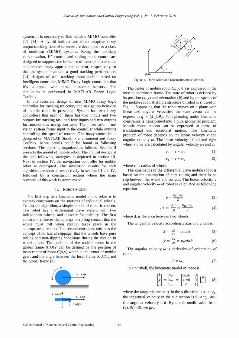
wheel plane. The position of the mobile robot in the
global frame X(O)Y can be defined by the position of
mass center of robot C(x,y) which is the center of mobile
gear; and the angle between the local frame XmCYm and
the global frame (θ).
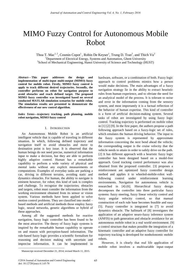
Figure 1. Ideal wheel and Kinematics model of robot.
The center of mobile robot (x, y, θ ) is expressed in the
inertial coordinate frame. The state of robot is defined by
its position (x, y) and orientation (θ) and by the speeds of
the mobile robot. A simple structure of robot is showed in
Fig. 1. Supposing that the robot moves on a plane with
linear and angular velocities, the state vector can be
express as 𝑞 ̇ = (�̇�, �̇�, �̇�). Path planning under kinematic
constraints is transformed into a pure geometric problem.
Mobile robot motion can be expressed in terms of
translational and rotational motion. The kinematic
problem of robot depends on the linear velocity v and
angular velocity ω. The linear velocity of left and right
wheel vL, vR are calculated by angular velocity ωR and ωL
𝑣𝑅 = 𝑟 ∗ 𝜔𝑅 (1)
𝑣𝐿 = 𝑟 ∗ 𝜔𝐿 (2)
where r: is radius of wheel.
The kinematics of the differential drive mobile robot is
based on the assumption of pure rolling and there is no
slip between the wheel and surface. The linear velocity v
and angular velocity ω of robot is calculated as following
equation
𝑣 =𝑣𝑥+𝑣𝑦
2 (3)
𝜔 = 𝑑𝜃
𝑑𝑡=
𝑣𝑅−𝑣𝐿
𝑑 (4)
where d: is distance between two wheels.
The tangential velocity according x axis and y axis is:
�̇� = 𝑑𝑥
𝑑𝑡= 𝑣𝑐𝑜𝑠𝜃 (5)
�̇� = 𝑑𝑦
𝑑𝑡= 𝑣𝑅𝑠𝑖𝑛𝜃 (6)
The angular velocity ω is derivative of orientation of
robot
�̇� = ωR (7)
In a nutshell, the kinematic model of robot is:
[
�̇��̇�
�̇�
] = [𝑣𝑥
𝑣𝑦
𝜔] = [
𝑐𝑜𝑠𝜃 0𝑠𝑖𝑛𝜃 0
0 1] [
𝑣𝜔
] (8)
where the tangential velocity in the x direction is �̇� or 𝑣𝑥,
the tangential velocity in the y direction is �̇� or 𝑣𝑦, and
the angular velocity is �̇�. By simple modification from
(5), (6), (8), we get:
66
Journal of Automation and Control Engineering Vol. 4, No. 1, February 2016
©2016 Journal of Automation and Control Engineering
[
�̇��̇�
�̇�
] = [𝑣𝑥
𝑣𝑦
𝜔] = [
1
2𝑐𝑜𝑠𝜃
1
2𝑐𝑜𝑠𝜃
1
2𝑠𝑖𝑛𝜃
1
2𝑠𝑖𝑛𝜃
0 −1/𝑑
] [𝜔𝑅
𝜔𝐿] (9)
This above kinematic equation is used for simulation
in this research. This model is referred to as a kinematic
model since it describes the velocities of the vehicle but
not the forces or torques that cause the velocity.
III. TRAJECTORY TRACKING OF MOBILE OF ROBOT
USING MIMO FUZZY
A behavior in a mobile robot navigation system usually represents a concern of the robot in which follow the path or avoid obstacles, target seeking are the most important task. Kinematics constraint in two dimensional workspaces is discussed in section II. Each robot has an image and an array of infrared sensors for measuring the distances of obstacles around it, and the bearing of the target and a radio system for communicating with other robots. The information’s being sent among the robots are their positions, how far they are from the target, and whether reached the target or not. According to the information acquired by the robots using their sensors, some of the fuzzy control rules are activated accordingly.
The MIMO closed-loop control algorithm is demonstrated in this section for tracking trajectories. At each sample time, the calculation module calculate the error in location and orientation Δx, Δy, Δθ between the actual robot coordinates (x, y, θ) (which are received from sensors in the reality) and coordinates of the trajectory (xd, yd, θd). After that, the Distance and Angle is generated to be the inputs of Fuzzy controller. This controller is able to deliver appropriate action for mobile robot, velocity of left and right wheel (ωL , ωR) as two outputs. To control the system, we assume the universe of discourse for the two state variables to be 0 ≤ x1 (Distance) ≤ 10 (cm); -pi ≤ x2 (Angle) ≤ pi (rad). The universe of discourse for the control velocity of left and right wheel is 0 ≤ u1(ωL)≤ 6 rad/s, 0 ≤ u2( ωL)≤ 6 rad/s.
A. Constructing the Membership Functions
Five membership functions are considered with all are
of triangular member. The languages are Zero (Z), Near
(N), Medium (M), Far (F), Very Far (VF) and Big
Negative (BN), Negative (N), Zero (Z), Positive (P),
Positive Big (PB) for Distance, Angle respectively.
Linguistic variables like are positive Very Slow (VS),
Slow (S), Medium (M), Fast (F), Very Fast (VF) defined
for ωL, ωR. The parameters defining the functions are
listed in Table I. The membership functions describes
above are depicted in Fig. 2
TABLE I. PARAMETERS FOR INPUTS AND OUTPUTS FUZZY
CONTROLLER
Variables Z
[0 0 2.5]
N [0 2.5 5]
M [2.5 5
7.5]
F [5 7.5
10]
VF [7.5 10
12.5]
X1(cm)
X2 (rad) BN
[ -1 -0.5 -0.1]
N
[-0.5 -0.1
0]
Z
[-0.1 0
0.1]
P
[0 0.1
0.5]
BP
[0.1 0.5 1]
U1, U2 (rad/s) VS
[0 0 1.5]
S
[0 1.5 3]
M
[1.5 3 4.5]
F
[3 4.5 6]
VF
[4.5 6 7.5]
B. Constructing the Rule Base
In order to satisfy the control objective it is necessary
to design a fuzzy logic control for the real velocities of
the mobile robot which use linguistic variables in the
inputs and outputs. After the stage of constructing
membership functions, we construct the FAM (Fuzzy
Associative Memory) table for the rule bases, which is
shown in Table II. The expert system is developed based
on the IF- THEN rules as 25 following rules to control
robot tracking defined trajectory. For example the first
rule is:
IF (Angle is Big Negative and Distances is Zero)
THEN (Velocity of right wheel is Very slow and Velocity
of left wheel is Very Fast)
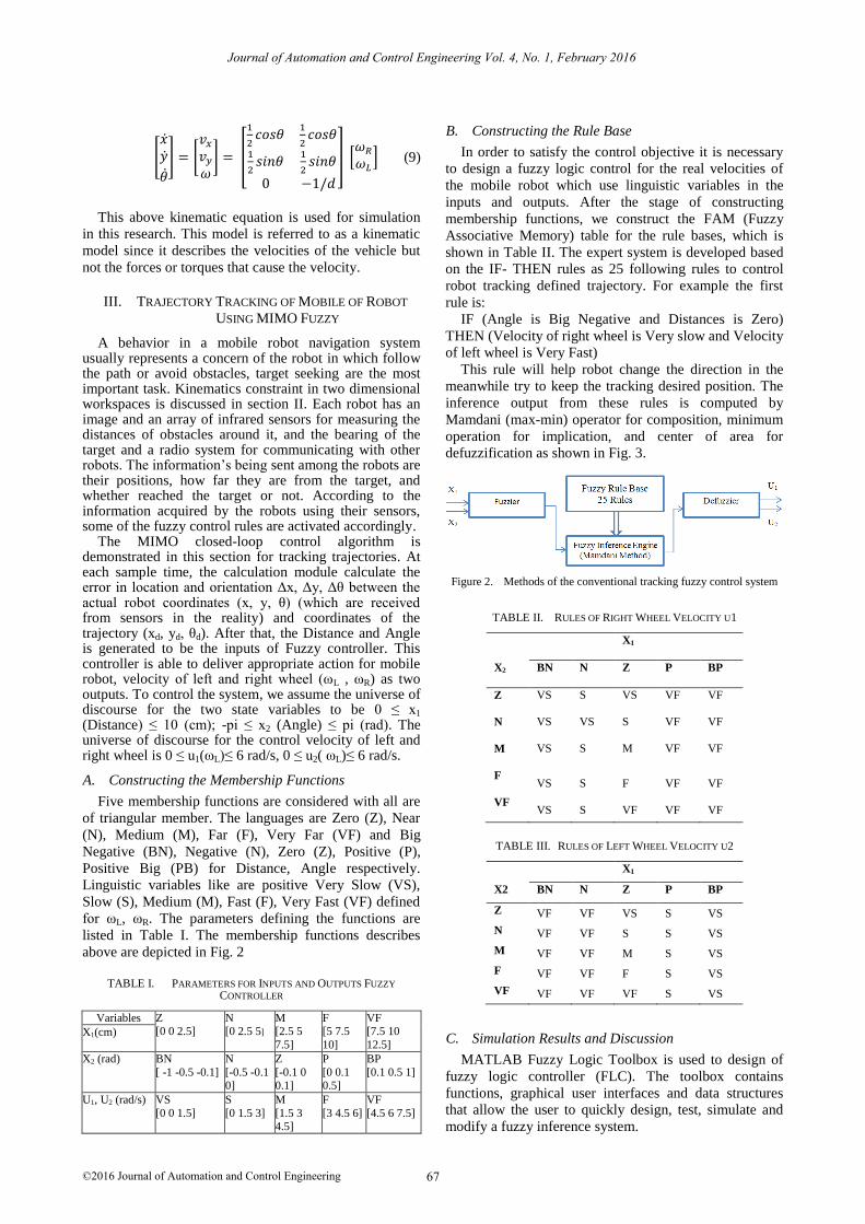
This rule will help robot change the direction in the
meanwhile try to keep the tracking desired position. The
inference output from these rules is computed by
Mamdani (max-min) operator for composition, minimum
operation for implication, and center of area for
defuzzification as shown in Fig. 3.
Figure 2. Methods of the conventional tracking fuzzy control system
TABLE II.
RULES OF RIGHT WHEEL VELOCITY U1
X1
X2
BN
N
Z
P
BP
Z
VS
S
VS
VF
VF
N
VS
VS
S
VF
VF
M
VS
S
M
VF
VF
F
VS
S
F
VF
VF
VF
VS
S
VF
VF
VF
TABLE III.
RULES OF LEFT WHEEL VELOCITY U2
X1
X2
BN
N
Z
P
BP
Z
VF
VF
VS
S
VS
N
VF
VF
S
S
VS
M
VF
VF
M
S
VS
F
VF
VF
F
S
VS
VF
VF
VF
VF
S
VS
C. Simulation Results and Discussion
MATLAB Fuzzy Logic Toolbox is used to design of
fuzzy logic controller (FLC). The toolbox contains
functions, graphical user interfaces and data structures
that allow the user to quickly design, test, simulate and
modify a fuzzy inference system.
67
Journal of Automation and Control Engineering Vol. 4, No. 1, February 2016
©2016 Journal of Automation and Control Engineering
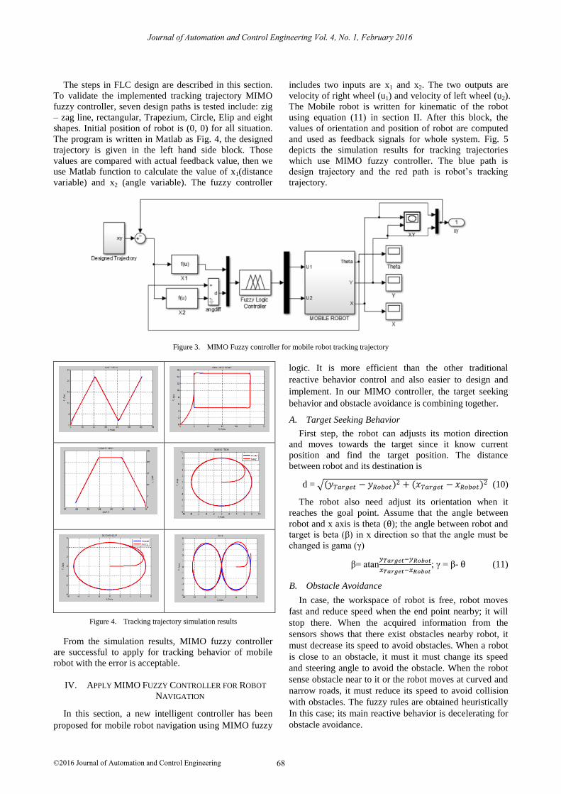
The steps in FLC design are described in this section.
To validate the implemented tracking trajectory MIMO
fuzzy controller, seven design paths is tested include: zig
– zag line, rectangular, Trapezium, Circle, Elip and eight
shapes. Initial position of robot is (0, 0) for all situation.
The program is written in Matlab as Fig. 4, the designed
trajectory is given in the left hand side block. Those
values are compared with actual feedback value, then we
use Matlab function to calculate the value of x1(distance
variable) and x2 (angle variable). The fuzzy controller
includes two inputs are x1 and x2. The two outputs are
velocity of right wheel (u1) and velocity of left wheel (u2).
The Mobile robot is written for kinematic of the robot
using equation (11) in section II. After this block, the
values of orientation and position of robot are computed
and used as feedback signals for whole system. Fig. 5
depicts the simulation results for tracking trajectories
which use MIMO fuzzy controller. The blue path is
design trajectory and the red path is robot’s tracking
trajectory.
Figure 3. MIMO Fuzzy controller for mobile robot tracking trajectory
Figure 4. Tracking trajectory simulation results
From the simulation results, MIMO fuzzy controller
are successful to apply for tracking behavior of mobile
robot with the error is acceptable.
IV. APPLY MIMO FUZZY CONTROLLER FOR ROBOT
NAVIGATION
In this section, a new intelligent controller has been
proposed for mobile robot navigation using MIMO fuzzy
logic. It is more efficient than the other traditional
reactive behavior control and also easier to design and
implement. In our MIMO controller, the target seeking
behavior and obstacle avoidance is combining together.
A. Target Seeking Behavior
First step, the robot can adjusts its motion direction
and moves towards the target since it know current
position and find the target position. The distance
between robot and its destination is
d = √(𝑦𝑇𝑎𝑟𝑔𝑒𝑡 − 𝑦𝑅𝑜𝑏𝑜𝑡)2 + (𝑥𝑇𝑎𝑟𝑔𝑒𝑡 − 𝑥𝑅𝑜𝑏𝑜𝑡)2 (10)
The robot also need adjust its orientation when it
reaches the goal point. Assume that the angle between
robot and x axis is theta (θ); the angle between robot and
target is beta (β) in x direction so that the angle must be
changed is gama (γ)
β= atan𝑦𝑇𝑎𝑟𝑔𝑒𝑡−𝑦𝑅𝑜𝑏𝑜𝑡
𝑥𝑇𝑎𝑟𝑔𝑒𝑡−𝑥𝑅𝑜𝑏𝑜𝑡; γ = β- θ (11)
B. Obstacle Avoidance
In case, the workspace of robot is free, robot moves
fast and reduce speed when the end point nearby; it will
stop there. When the acquired information from the
sensors shows that there exist obstacles nearby robot, it
must decrease its speed to avoid obstacles. When a robot
is close to an obstacle, it must it must change its speed
and steering angle to avoid the obstacle. When the robot
sense obstacle near to it or the robot moves at curved and
narrow roads, it must reduce its speed to avoid collision
with obstacles. The fuzzy rules are obtained heuristically
In this case; its main reactive behavior is decelerating for
obstacle avoidance.
68
Journal of Automation and Control Engineering Vol. 4, No. 1, February 2016
©2016 Journal of Automation and Control Engineering
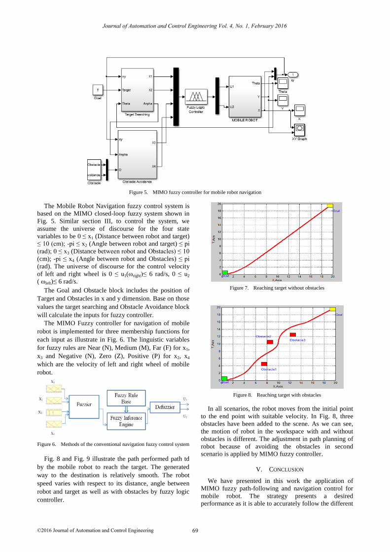
Figure 5. MIMO fuzzy controller for mobile robot navigation
The Mobile Robot Navigation fuzzy control system is
based on the MIMO closed-loop fuzzy system shown in
Fig. 5. Similar section III, to control the system, we
assume the universe of discourse for the four state
variables to be 0 ≤ x1 (Distance between robot and target)
≤ 10 (cm); -pi ≤ x2 (Angle between robot and target) ≤ pi
(rad); 0 ≤ x3 (Distance between robot and Obstacles) ≤ 10
(cm); -pi ≤ x4 (Angle between robot and Obstacles) ≤ pi
(rad). The universe of discourse for the control velocity
of left and right wheel is 0 ≤ u1(ωright)≤ 6 rad/s, 0 ≤ u2
( ωleft)≤ 6 rad/s.
The Goal and Obstacle block includes the position of
Target and Obstacles in x and y dimension. Base on those
values the target searching and Obstacle Avoidance block
will calculate the inputs for fuzzy controller.
The MIMO Fuzzy controller for navigation of mobile
robot is implemented for three membership functions for
each input as illustrate in Fig. 6. The linguistic variables
for fuzzy rules are Near (N), Medium (M), Far (F) for x1,
x3 and Negative (N), Zero (Z), Positive (P) for x2, x4
which are the velocity of left and right wheel of mobile
robot.
Figure 6.
Methods of the conventional navigation fuzzy control system
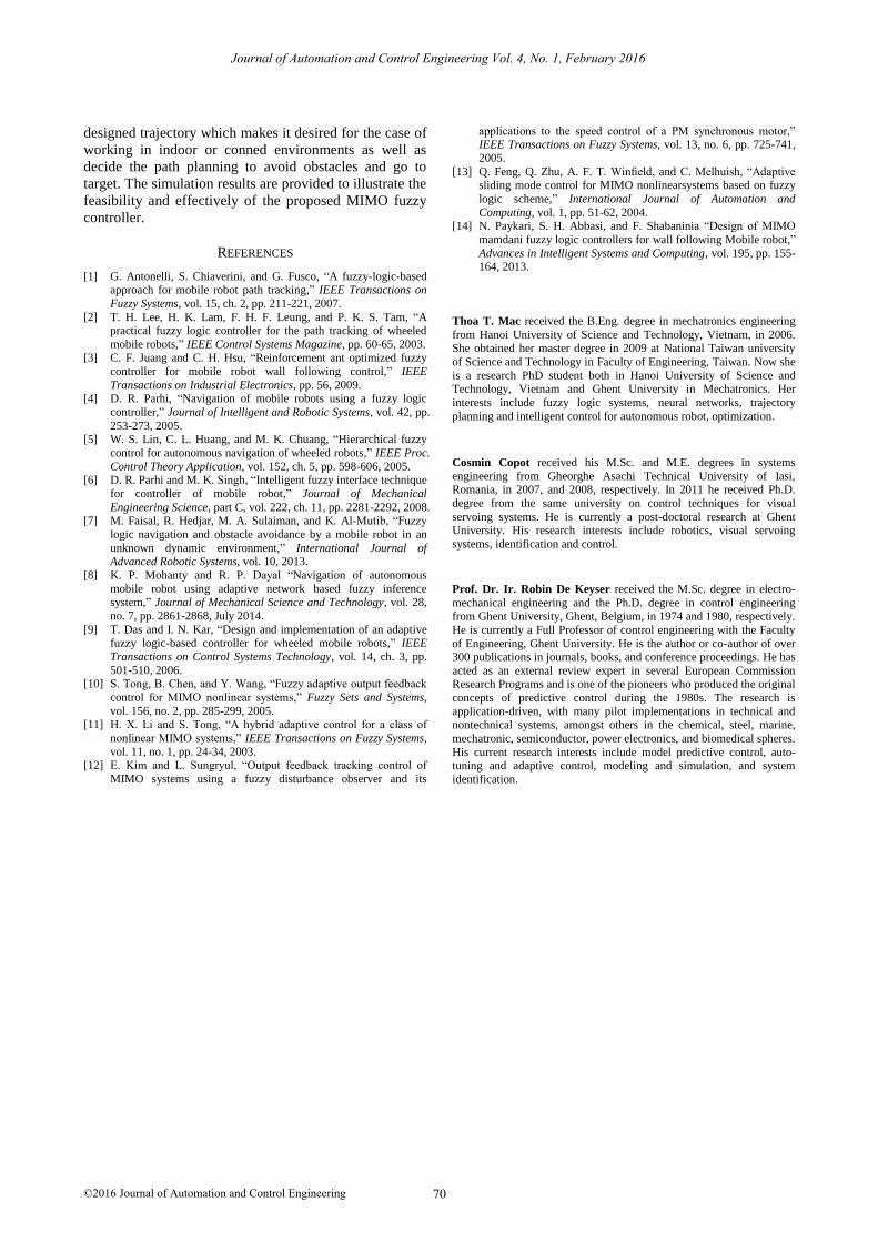
Fig. 8 and Fig. 9 illustrate the path performed path td
by the mobile robot to reach the target. The generated
way to the destination is relatively smooth. The robot
speed varies with respect to its distance, angle between
robot and target as well as with obstacles by fuzzy logic
controller.
Figure 7. Reaching target without obstacles
Figure 8. Reaching target with obstacles
In all scenarios, the robot moves from the initial point
to the end point with suitable velocity. In Fig. 8, three
obstacles have been added to the scene. As we can see,
the motion of robot in the workspace with and without
obstacles is different. The adjustment in path planning of
robot because of avoiding the obstacles in second
scenario is applied by MIMO fuzzy controller.
V. CONCLUSION
We have presented in this work the application of
MIMO fuzzy path-following and navigation control for
mobile robot. The strategy presents a desired
performance as it is able to accurately follow the different
69
Journal of Automation and Control Engineering Vol. 4, No. 1, February 2016
©2016 Journal of Automation and Control Engineering
designed trajectory which makes it desired for the case of
working in indoor or conned environments as well as
decide the path planning to avoid obstacles and go to
target. The simulation results are provided to illustrate the
feasibility and effectively of the proposed MIMO fuzzy
controller.
REFERENCES
[1] G. Antonelli, S. Chiaverini, and G. Fusco, “A fuzzy-logic-based approach for mobile robot path tracking,” IEEE Transactions on
Fuzzy Systems, vol. 15, ch. 2, pp. 211-221, 2007.
[2] T. H. Lee, H. K. Lam, F. H. F. Leung, and P. K. S. Tam, “A practical fuzzy logic controller for the path tracking of wheeled
mobile robots,” IEEE Control Systems Magazine, pp. 60-65, 2003. [3] C. F. Juang and C. H. Hsu, “Reinforcement ant optimized fuzzy
controller for mobile robot wall following control,” IEEE
Transactions on Industrial Electronics, pp. 56, 2009. [4] D. R. Parhi, “Navigation of mobile robots using a fuzzy logic
controller,” Journal of Intelligent and Robotic Systems, vol. 42, pp.
253-273, 2005. [5] W. S. Lin, C. L. Huang, and M. K. Chuang, “Hierarchical fuzzy
control for autonomous navigation of wheeled robots,” IEEE Proc.
Control Theory Application, vol. 152, ch. 5, pp. 598-606, 2005. [6] D. R. Parhi and M. K. Singh, “Intelligent fuzzy interface technique
for controller of mobile robot,” Journal of Mechanical
Engineering Science, part C, vol. 222, ch. 11, pp. 2281-2292, 2008. [7] M. Faisal, R. Hedjar, M. A. Sulaiman, and K. Al-Mutib, “Fuzzy
logic navigation and obstacle avoidance by a mobile robot in an
unknown dynamic environment,” International Journal of Advanced Robotic Systems, vol. 10, 2013.
[8] K. P. Mohanty and R. P. Dayal “Navigation of autonomous
mobile robot using adaptive network based fuzzy inference system,” Journal of Mechanical Science and Technology, vol. 28,
no. 7, pp. 2861-2868, July 2014.
[9] T. Das and I. N. Kar, “Design and implementation of an adaptive fuzzy logic-based controller for wheeled mobile robots,” IEEE
Transactions on Control Systems Technology, vol. 14, ch. 3, pp.
501-510, 2006. [10] S. Tong, B. Chen, and Y. Wang, “Fuzzy adaptive output feedback
control for MIMO nonlinear systems,” Fuzzy Sets and Systems,
vol. 156, no. 2, pp. 285-299, 2005. [11] H. X. Li and S. Tong, “A hybrid adaptive control for a class of
nonlinear MIMO systems,” IEEE Transactions on Fuzzy Systems,
vol. 11, no. 1, pp. 24-34, 2003. [12] E. Kim and L. Sungryul, “Output feedback tracking control of
MIMO systems using a fuzzy disturbance observer and its
applications to the speed control of a PM synchronous motor,” IEEE Transactions on Fuzzy Systems, vol. 13, no. 6, pp. 725-741,
2005.
[13] Q. Feng, Q. Zhu, A. F. T. Winfield, and C. Melhuish, “Adaptive sliding mode control for MIMO nonlinearsystems based on fuzzy
logic scheme,” International Journal of Automation and
Computing, vol. 1, pp. 51-62, 2004. [14] N. Paykari, S. H. Abbasi, and F. Shabaninia “Design of MIMO
mamdani fuzzy logic controllers for wall following Mobile robot,”
Advances in Intelligent Systems and Computing, vol. 195, pp. 155-164, 2013.
Thoa T. Mac received the B.Eng. degree in mechatronics engineering
from Hanoi University of Science and Technology, Vietnam, in 2006. She obtained her master degree in 2009 at National Taiwan university
of Science and Technology in Faculty of Engineering, Taiwan. Now she
is a research PhD student both in Hanoi University of Science and Technology, Vietnam and Ghent University in Mechatronics. Her
interests include fuzzy logic systems, neural networks, trajectory
planning and intelligent control for autonomous robot, optimization.
Cosmin Copot
received his M.Sc. and M.E.
degrees in systems
engineering from Gheorghe Asachi
Technical University of Iasi, Romania, in 2007, and 2008, respectively. In 2011 he received Ph.D.
degree from the same university on control techniques for visual
servoing systems. He is currently a post-doctoral research at Ghent University. His research interests include robotics, visual servoing
systems, identification and control.
Prof. Dr. Ir. Robin De Keyser
received the M.Sc. degree in electro-
mechanical engineering and the Ph.D. degree in control
engineering from Ghent University, Ghent, Belgium, in 1974 and 1980, respectively.
He is currently a Full Professor of control engineering with the Faculty
of Engineering, Ghent University. He is the author or co-author of over 300 publications in journals, books, and conference proceedings. He has
acted as an external review expert in several European Commission Research Programs and is one of the pioneers who produced the original
concepts of predictive control during the 1980s. The research is
application-driven, with many pilot implementations in technical and nontechnical systems, amongst others in the chemical, steel, marine,
mechatronic, semiconductor, power electronics, and biomedical spheres.
His current research interests include model predictive control, auto-tuning and adaptive control, modeling and simulation, and system
identification.
70
Journal of Automation and Control Engineering Vol. 4, No. 1, February 2016
©2016 Journal of Automation and Control Engineering

![Mobile Robot Navigation using Fuzzy Limit- Cycles in ... · of fuzzy logic in mobile robot navigation, namely, behavior-based approach [22] and classical fuzzy rule based approach](https://img.pdfslide.net/doc/110x75/5eda087bbb309434ee032343/mobile-robot-navigation-using-fuzzy-limit-cycles-in-of-fuzzy-logic-in-mobile.jpg)