Embed Size (px)
Citation preview
1
Jambor, Richard
From: PostmasterSent: Monday, September 08, 2008 5:22 PMTo: Jambor, RichardSubject: Delivery Notification <[email protected],[email protected]>Attachments: ATT269208.txt; RIN 1219-AB60
This is a delivery status notification, automatically generated by MTA johnmail01.fmglobal.com on Mon, 08 Sep 2008 17:21:58 ‐0400 Regarding recipient(s) : zzmsha‐[email protected],[email protected] Delivery status : Failed. Message could not be delivered to domain <dol.gov> .Error while sending data. MTA Response :400 The original message headers are included as attachment.
-----Original Message----- From: Jambor, Richard [mailto:[email protected]] Sent: Tuesday, September 09, 2008 9:21 AM To: zzMSHA-Standards - Comments to Fed Reg Group Subject: FW: RIN 1219-AB60 Attached is the original email that resulted in a Delivery Failure from domain <dol.gov> _____________________________________________ From: Jambor, Richard Sent: Monday, September 08, 2008 2:38 PM To: '[email protected]' Cc: Norcott, Jill E; Moore, Larry; Ferron, Richard; '[email protected]' Subject: RIN 1219-AB60 To Whom It May Concern: FM Global Research has been working on conveyor belt flammability testing for loss prevention purposes, both in-plant and underground for several years. We feel that there should be consideration of additional testing methodologies accepted for conveyor belt flammability and smoke generation. I have attached three documents to support our request for consideration: 1) a 1995 letter from Factory Mutual Research, now FM Global Research, discussing the test methodology which is now included in ASTM E2058, Standard Test Methods for Measurement of Synthetic Polymer Material Flammability Using a Fire Propagation Apparatus (FPA) 2) A power point presentation on the use of FPI for conveyor belt flammability evaluations and 3) FM Approvals 4998 Standard, Approval Standard for Class 1 Conveyor Belting, which includes the determination of FPI according to ASTM E2058. <<SILVEY.pdf>> <<Conveyor UTH - Part 3 - FPI Testing.ppt>> <<4998.pdf>> In view of the current request, [Federal Register: August 21, 2008 (Volume 73, Number 163)] [Proposed Rules] [Page 49373] From the Federal Register Online via GPO Access [wais.access.gpo.gov] [DOCID:fr21au08-19] ======================================================================= ----------------------------------------------------------------------- DEPARTMENT OF LABOR Mine Safety and Health Administration 30 CFR Part 18 RIN 1219-AB60

The test methodologies we are suggesting for consideration by MSHA, in conjunction with the ASTM E2058 Test Standard can evaluate the flammability of conveyor belts as well as smoke generation. However, toxicity evaluations for smoke would require other tests not covered within this comments document. We look forward to an opportunity to prepare a formal proposal to MSHA for consideration of our Conveyor Belt Test methodology and criteria for acceptance. Respectfully Submitted, R. Jambor, Senior Engineer FM Approvals/Materials Group Ph +1 401 567 5010 Fax +1 401 568 6241 Email [email protected]
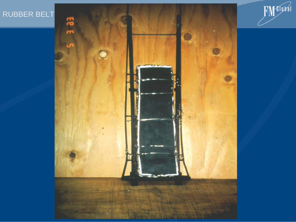
RUBBER BELT CONVEYORS
UNDERSTANDING THE HAZARDS OF RUBBER BELT CONVEYOR SYSTEMS
PART 3 – CLASSIFICATION OF CONVEYOR BELTS USING A FIRE PROPAGATION INDEX
RUBBER BELT CONVEYORS
Understanding the FM Global FPI Test Protocol for Flame-Resistant Conveyor Belts
• Define FPI• Test procedure• Test results• Approval Standard
RUBBER BELT CONVEYORS
RUBBER BELT CONVEYORS
RUBBER BELT CONVEYORS
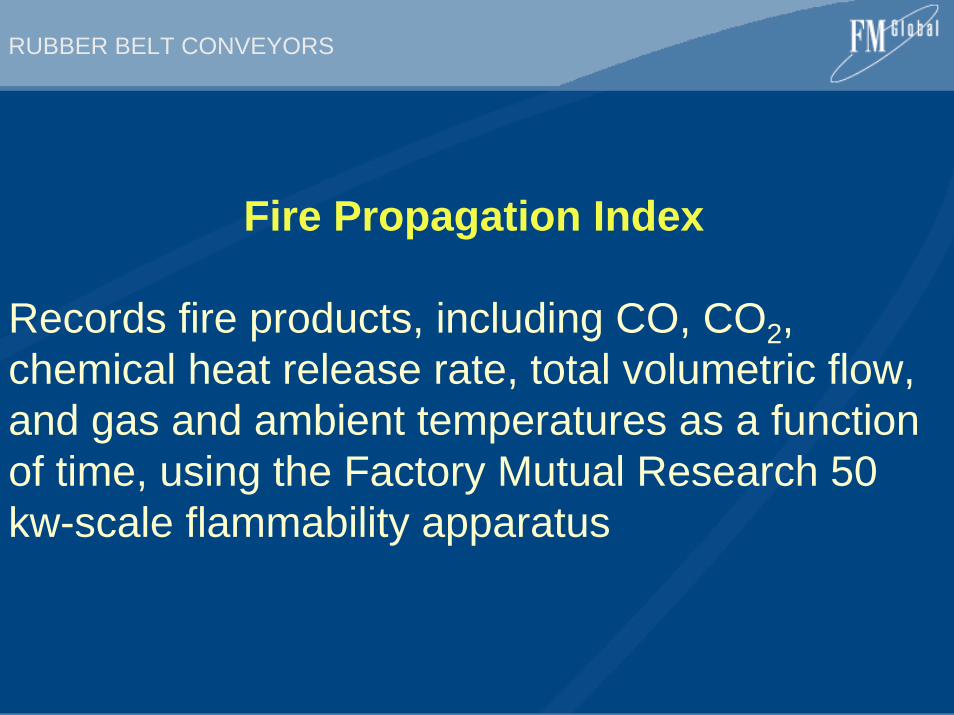
Fire Propagation Index
Records fire products, including CO, CO2, chemical heat release rate, total volumetric flow, and gas and ambient temperatures as a function of time, using the Factory Mutual Research 50 kw-scale flammability apparatus
RUBBER BELT CONVEYORS
RUBBER BELT CONVEYORS
RUBBER BELT CONVEYORS
RUBBER BELT CONVEYORS
RUBBER BELT CONVEYORS
RUBBER BELT CONVEYORS
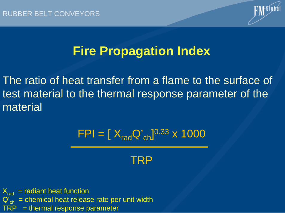
Fire Propagation Index
The ratio of heat transfer from a flame to the surface of test material to the thermal response parameter of the material
FPI = [ XradQ’ch]0.33 x 1000
TRP
Xrad = radiant heat functionQ’ch = chemical heat release rate per unit widthTRP = thermal response parameter
RUBBER BELT CONVEYORS
0
2
4
6
8
1
0
12
14
0 50 100 150 200 250 300
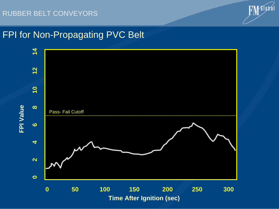
FPI for Non-Propagating PVC BeltFP
I Val
ue Pass- Fail Cutoff
Time After Ignition (sec)
RUBBER BELT CONVEYORS
0
2
4
6
8
10
12
1
4
16
1
8
0 100 200 300 400 500 600
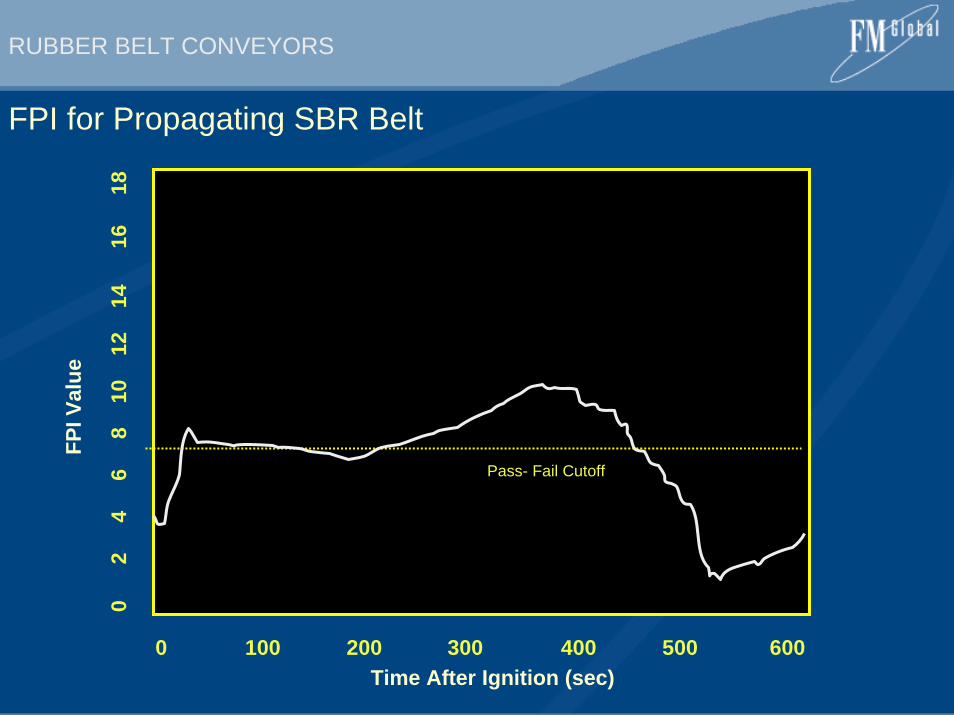
FPI for Propagating SBR BeltFP
I Val
ue
Pass- Fail Cutoff
Time After Ignition (sec)
RUBBER BELT CONVEYORS
0
5
1
0
20
25
30
35
4
0
0 200 400 600 800 1000
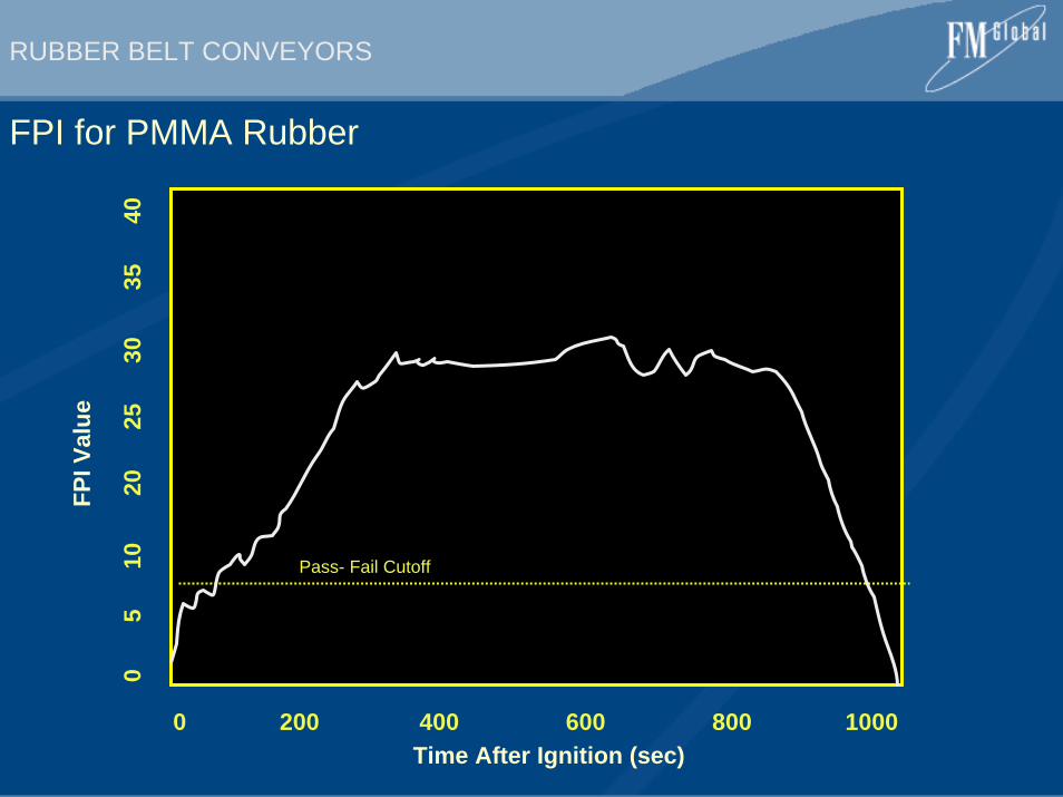
FPI for PMMA RubberFP
I Val
ue
Pass- Fail Cutoff
Time After Ignition (sec)
RUBBER BELT CONVEYORS
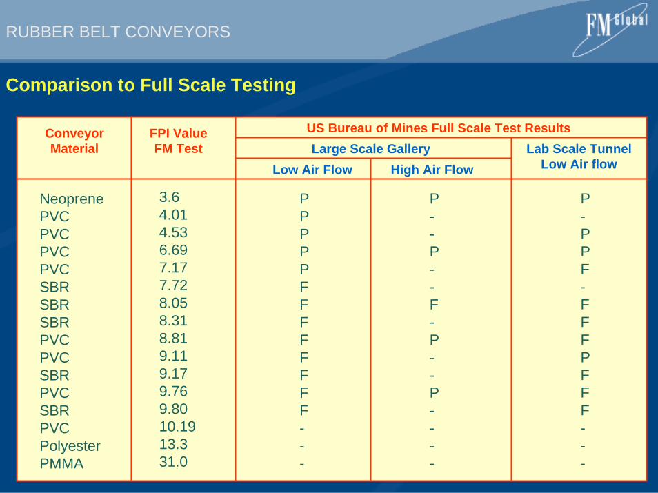
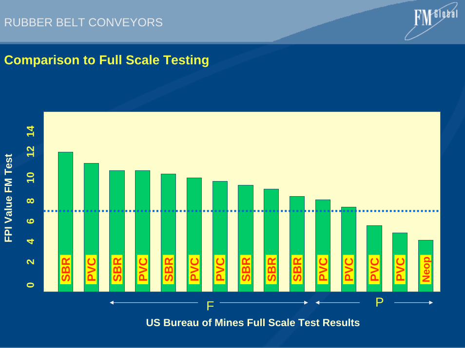
Comparison to Full Scale Testing
ConveyorMaterial
FPI ValueFM Test
US Bureau of Mines Full Scale Test ResultsLarge Scale Gallery Lab Scale Tunnel
Low Air flowLow Air Flow High Air Flow
NeoprenePVCPVCPVCPVCSBRSBRSBRPVCPVCSBRPVCSBRPVCPolyesterPMMA
3.64.014.536.697.177.728.058.318.819.119.179.769.8010.1913.331.0
PPPPPFFFFFFFF---
P--P--F-P--P----
P-PPF-FFFPFFF---
RUBBER BELT CONVEYORS
Comparison to Full Scale Testing
US Bureau of Mines Full Scale Test Results
FPI V
alue
FM
Tes
t
F P
0
2
4
6
8
10
1
2 1
4
SBR
Neo
p
PVC
PVC
PVC
PVC
PVC
PVC
SBR
SBR
SBR
SBR
PVC
SBR
PVC
RUBBER BELT CONVEYORS
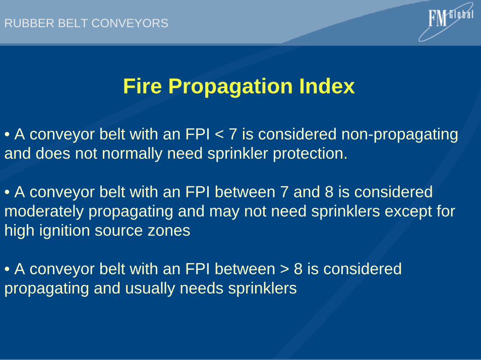
Fire Propagation Index
• A conveyor belt with an FPI < 7 is considered non-propagating and does not normally need sprinkler protection.
• A conveyor belt with an FPI between 7 and 8 is considered moderately propagating and may not need sprinklers except for high ignition source zones
• A conveyor belt with an FPI between > 8 is considered propagating and usually needs sprinklers
RUBBER BELT CONVEYORS
Approval StandardClass 1 Conveyor Belting
FM Global Approval Requirements for “Non-Propagating” Conveyor Belts
RUBBER BELT CONVEYORS
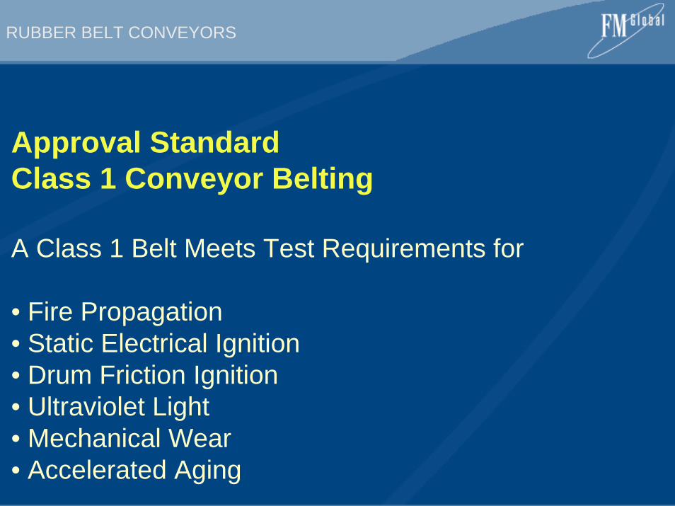
Approval StandardClass 1 Conveyor Belting
A Class 1 Belt Meets Test Requirements for
• Fire Propagation• Static Electrical Ignition• Drum Friction Ignition• Ultraviolet Light • Mechanical Wear• Accelerated Aging
RUBBER BELT CONVEYORS
Main Conclusions
• An FPI has successfully been used to classify flame resistance of conveyor belting• Excellent agreement was found between the FPI values obtained in the FM small scale apparatus and results from the USBM large scale fire gallery tests• A conveyor belt with an FPI of 7 or less is considered “non-propagating”• An Approval Standard has been developed to classify belt samples using FPI values• As of 2004 there are no Approved belts but some belts have passed specific contract or risk service tests
Approval Standard
for
Class 1Conveyor Belting
Class Number 4998
August 1995
©2002 FM Global Technologies LLC. All rights reserved.
Foreword
FM Approvals are intended to verify that the products and services described will meet stated conditions ofperformance, safety and quality useful to the ends of property conservation. The purpose of FM ApprovalStandards is to present the criteria for FM Approval of various types of products and services, as guidance forFM Approvals personnel, manufacturers, users and authorities having jurisdiction.
Products submitted for Approval shall demonstrate that they meet the intent of the Approval Standard, and thatquality control in manufacturing and/or applications shall ensure a consistently uniform and reliable product orservice. FM Approval Standards strive to be performance-oriented and to facilitate technological development.
For examining equipment, materials and services, FM Approval Standards:
a) must be useful to the ends of property conservation by preventing, limiting or not causing damageunder the conditions stated by the Approval listing; and
b) must be readily identifiable.
Continuance of Approval and Listing depends on compliance with the Approval agreement, satisfactoryperformance in the field, on successful re-examinations of equipment, materials, and services as appropriate, andon periodic follow-up audits of the manufacturing facility or service/application.
FM Global Technologies LLC reserves the right in its sole judgement to change or revise its standards, criteria,methods, or procedures.
TABLE OF CONTENTSI INTRODUCTION ....................................................................................................................................................................... 1
1.1 Purpose .............................................................................................................................................................................. 11.2 Scope ................................................................................................................................................................................. 11.3 Basis For FM Approval .................................................................................................................................................... 11.4 Basis For Continued Approval ........................................................................................................................................... 21.5 Basis For Requirements .................................................................................................................................................... 21.6 Effective Date .................................................................................................................................................................... 21.7 System Of Units ................................................................................................................................................................ 2
II GENERAL INFORMATION ................................................................................................................................................... 32.1 Product Information .......................................................................................................................................................... 32.2 Requirements ..................................................................................................................................................................... 32.3 Recognition ........................................................................................................................................................................ 3
III APPLICABLE DOCUMENTS AND GLOSSARY .............................................................................................................. 33.1 Applicable Documents ...................................................................................................................................................... 33.2 Glossary ............................................................................................................................................................................. 4
IV GENERAL REQUIREMENTS .............................................................................................................................................. 54.1 Markings ............................................................................................................................................................................ 54.2 Instructions ........................................................................................................................................................................ 54.3 Drawings/Formulations/Specifications Required ............................................................................................................. 54.4 Manufacturer’s Responsibilities ........................................................................................................................................ 64.5 Observation of Test Sample Production ........................................................................................................................... 6
V PERFORMANCE REQUIREMENTS .................................................................................................................................... 65.1 Flammability Characterization .......................................................................................................................................... 65.2 Anti-Static Electricity Test ................................................................................................................................................ 65.3 Accelerated Aging Test ..................................................................................................................................................... 75.4 Drum Friction Test ............................................................................................................................................................ 7
VI OPERATIONS REQUIREMENTS ....................................................................................................................................... 86.1 Demonstrated Quality Control Program ........................................................................................................................... 86.2 Facilities and Procedures Audit (F&PA) .......................................................................................................................... 9
APPENDIX A UNITS OF MEASUREMENT ........................................................................................................................... 10
APPENDIX B APPROVAL MARKS ......................................................................................................................................... 11
APPENDIX C DETERMINATION OF THE FIRE PROPAGATION INDEX (FPI) ........................................................ 12
APPENDIX D PILOTED IGNITION TEST METHOD .......................................................................................................... 14
APPENDIX E FIRE PROPAGATION TEST METHOD ........................................................................................................ 18
APPENDIX F FM APPROVALS ACCELERATED AGING TEST METHOD ................................................................... 21

I INTRODUCTION
1.1 Purpose
This standard states FM Approval requirements for Class 1 conveyor belting. The establishment of such aclassification is used in determining acceptable fire protection requirements applicable to specific installations.
1.2 Scope
1.2.1 This standard sets performance requirements for establishing a classification for horizontal, inclined, andvertical conveyor belts made from plastics, fibers, and natural and synthetic rubbers used to transportmaterials in commercial or industrial applications.
1.2.2 This standard examines the ability of conveyor belting to limit fire spread by measuring its resistance ofself-sustaining fire propagation. This standard also examines surface buildup of static electricity, friction,and the adverse effects on fire performance caused by ultraviolet (UV) and/or water exposure andmechanical wear.
1.2.3 This standard is not intended to determine the suitability for all end-use conditions of this product.Conditions such as strength, elongation, durability, impact resistance, operating temperature range,corrosion resistance, etc., are not evaluated as part of this Approval examination.
1.2.4 This standard provides a means for determining the sprinkler protection requirements needed strictly dueto the flammability characteristics of the conveyor belting. The effect of conveying combustible materials,enclosure housings constructed of combustible material or the presence of ordinary combustibles near orunder the conveyor belt have not been considered. The sprinkler protection requirements when theseconditions exist are not included or determined by this standard.
1.3 Basis For FM Approval
FM Approval is based upon satisfactory evaluation of the product and the manufacturer in the following majorareas:
1.3.1 Examination and tests on production samples to evaluate:
• the ability to resist self-sustaining fire propagation;
• the ability to retain its fire performance properties after accelerated weathering (UV and/or water)exposure and mechanical wear;
• the ability to develop sufficient conductance to prevent the buildup of static electricity;
• the temperature on a drum’s surface created from friction between a spinning drum and a ‘‘locked’’ belt;and
• the suitability and reliability of the product, as far as practical.
1.3.2 Examination of the manufacturing facilities and audit of quality control to evaluate the manufacturer’sability to produce the product as examined and tested, and the marking procedures used to identify theproduct. These examinations are repeated as part of FM Approvals’ product follow-up program.
August 1995 4998
FM APPROVALS 1
1.4 Basis For Continued Approval
Continued Approval is based upon:
• production or availability of the product as currently Approved;
• the continued use of acceptable quality control procedures;
• satisfactory field experience;
• compliance with the terms stipulated in the Approval agreement; and
• re-examination of production samples for continued conformity to requirements.
1.5 Basis For Requirements
1.5.1 The requirements of this standard are based on experience, research, testing and/or the standards ofFM Approvals, and other national and international organizations. The advice of manufacturers, users,trade associations and loss control specialists was also considered.
1.5.2 Meeting these requirements qualifies a product as Approved Class 1 conveyor belting. Requirementsprohibit component substitution or modification without prior authorization by FM Approvals.
1.5.3 The requirements of this standard reflect tests and practices used to examine characteristics of conveyorbelting for the purpose of obtaining FM Approval. These requirements are intended primarily as guides,and strict conformity is not always mandatory. Conveyor belting having characteristics not anticipated bythis standard may be Approved if performance equal or superior to that required by this standard isdemonstrated, or if the intent of the standard is met. Alternatively, conveyor belting which does meet allthe requirements identified in this standard may not be Approved if other conditions which adversely affectperformance exist or if the intent of this standard is not met.
1.6 Effective Date
The effective date of an Approval Standard mandates that all products tested for Approval after the effective dateshall satisfy the requirements of that standard. Products Approved under a previous edition shall comply with thenew version by the effective date or else forfeit approval. The effective date shall apply to the entire Approvalstandard, or, where so indicated, only to specific paragraphs of the standard.
The effective date of this standard is for full compliance with all requirements is the date of issue.
1.7 System Of Units
Units of measurements are U.S. customary units. These are followed by their arithmetic equivalents in Inter-national System (SI) units, enclosed in parentheses. Appendix A lists the selected units for quantities dealt within testing these products; conversions to SI units are included. Conversion of U.S. customary units is inaccordance with ASTM E380.
4998 August 1995
2 FM APPROVALS
II GENERAL INFORMATION
2.1 Product Information
Conveyor belts, typically manufactured in laminated layers from plastics, fibers, and natural and syntheticrubbers, are used to transport a wide variety of materials. Past experience has shown that they are capable ofproviding a sufficient combustible loading, in and of themselves, which allows for fire to spread from one areato another, even in cases where the conveyed product and enclosing structure, if provided, are noncombustible.
2.2 Requirements
2.2.1 In order to qualify as a Class 1 Conveyor Belt, each conveyor belt shall satisfy all of the followingperformance criteria.
2.2.2 The Approval examination includes 1) observation of test sample manufacture, 2) flammability charac-terization of the conveyor belt 3) electrical conductance test, 4) testing to determine the effects ofmechanical wear on flammability characterization, 3) testing to determine the effects of UV and/or waterexposure on flammability characterization, 6) drum friction test, and 7) other tests as noted. A completereview of installation specifications and, at the discretion of FM Approvals, inspection of one or more fieldinstallations shall be conducted to assure, as far as possible, the practicality and reliability of productinstallation.
2.2.3 When different materials or polymers are used in the construction of the top and bottom surfaces, theabove tests may be required for both surfaces to verify that both surfaces meet the requirements of thisstandards.
2.3 Recognition
Conveyor belting meeting the requirements specified in this standard shall receive a listing in the ApprovalGuide as Class 1 Conveyor Belting. Limitations for use will be designated within parentheses following the Classdesignation. Any such limitations are based on the ability of the material to maintain its non-fire propagatingcharacteristics after extended exposure to simulated natural and mechanical elements. See Section 3.2 fordesignations and limitations on their use.
III APPLICABLE DOCUMENTS AND GLOSSARY
3.1 Applicable Documents
The following standards or reports are referenced in this document:
ASTM G53-93, ‘‘Standard Practice for Operating Light-and-Water Exposure Apparatus(Fluorescent UV — Condensation Type) for Exposure of Nonmetallic Materials’’
ASTM E380-93, ‘‘Practice for Use of the International System of Units (SI)’’
BSI BS 871:1981(1988), ‘‘Specification for Abrasive Papers and Cloths’’
August 1995 4998
FM APPROVALS 3
BSI BS 3289:1990, ‘‘Textile Carcasse Conveyor Belting for Use in Underground Mines(Including Fire Performance)’’
FM Global Property Loss Prevention Data Sheet 7-11, ‘‘Belt Conveyors’’, August 1987
FM Global Technical Advisory Bulletin ‘‘Conveyor Belt Flammability’’, July 1993
ISO 284 (1975), ‘‘Specification and Method of Test for Electrical Conductivity of Conveyor Belts’’
3.2 Glossary
Class 1 Conveyor Belting — Conveyor belting material that meets FM Approvals test requirements as non-firepropagating material and all other conditions of this standard. These materialsshow no adverse effects on their fire propagation properties after extended UV,water exposure and mechanical wear tests. The materials may be used in totallyenclosed, partially open, or open system applications.
Class 1 (U) Conveyor Belting — Conveyor belting material that meets FM Approvals test requirements as anon-fire propagating material and shows no adverse effects on its fire propa-gation properties after extended water exposure and mechanical wear, andexhibits suitable anti-static electricity properties. The materials may be usedin totally enclosed system applications or where conditions are wet but thereis no exposure to sunlight, such as underground mine tunnels.
Class 1 (TE) Conveyor Belting — Conveyor belting material that meets FM Approvals test requirements as anon-fire propagating material and exhibits suitable anti-static electricityproperties. These materials show no adverse effects on their fire propaga-tion properties from mechanical wear. However, they show adverse effectson their fire propagation properties from extended UV and /or water expo-sure. Use of these materials is restricted to totally enclosed systems whereextended water and UV exposure is minimal or nonexistent.
Conveyor Belt — A material handling product used to transport a wide variety of materials, usually of the rawbulk type. Belts vary in width and length. They are generally made from natural and syntheticrubbers and plastic.
Chemical Heat Release Rate (CHRR) — The actual heat release rate during the fire propagation process. It isdetermined from the generation rates of carbon monoxide and carbondioxide.
Fire Propagation Index (FPI) — A measure of the fire propagation tendency of a material. It is the ratio of theheat flux provided by the flame off the surface of the material and thematerial’s Thermal Response Parameter (TRP).
Heat Flux — The rate of heat flow measured across a given surface.
Non-Fire Propagating — The ability of a material to resist flame propagation and to limit the spread of firewithin the ignition zone.
Open System — A conveyor system with no housing or hood to protect the conveyor belting or conveyedmaterial from weather conditions such as rain, dew and sunlight.
4998 August 1995
4 FM APPROVALS
Partially Open System — A conveyor system having an enclosure with continuous openings along the sides orfloor. A conveyor with a weather hood or no floor would be an example of a partiallyopen system.
Thermal Response Parameter (TRP) — A property of a material describing its reaction to heat in terms ofignition temperature, thermal conductivity, density and specific heat;i.e. a measure of the ability for thermal wave penetration into amaterial.
Totally Enclosed System — A conveyor system having an enclosure that has no continuous openings along thesides or floor and serves to minimize or eliminate exposure of the conveyor beltingor conveyed material to potentially harmful weather conditions such as rain, dewand sunlight. Occasional openings such as doors or inspection hatches are per-mitted. Elevated or grade level structures or tubes, subgrade tunnels, mines, andother underground applications are examples of totally enclosed systems.
IV GENERAL REQUIREMENTS
4.1 Markings
4.1.1 Approved conveyor belting shall bear the following information:
• FM Approval Mark (See Appendix B)
• Manufacturer’s name
• Class designation
4.1.2 The markings shall be a repeating pattern placed along the edge of the bottom surface at 10 feet (3.0 m)linear intervals. They shall consist of a wear-resistant stencil, brand or other type suitable toFM Approvals, and be of a contrasting color for ease in identification.
4.1.3 Markings shall be applied only to products that meet FM Approval requirements and only within and onthe premises of the specific facility where the finished product was manufactured, and that are inspectedunder the FM Approvals Facilities and Procedures Audit Program.
4.2 Instructions
Printed installation instructions shall be provided by the manufacturer detailing the necessary installationprocedures to be followed by installers.
4.3 Drawings/Formulations/Specifications Required
4.3.1 Detailed drawings shall be submitted for each type of conveyor belt for which Approval is desired. At aminimum, the drawings shall show the product name/number, allowable widths, thicknesses and identi-fication of each layer of material.
August 1995 4998
FM APPROVALS 5
4.3.2 Proprietary product formulations, raw materials and suppliers, and a manufacturing process schematicdiagram for each product shall be submitted to FM Approvals for review and kept on file at FM Approvalson a confidential basis.
4.4 Manufacturer’s Responsibilities
4.4.1 All Approved conveyor belting shall be manufactured with the identical raw materials, additives, andprocesses as originally tested.
4.4.2 The manufacturer shall notify FM Approvals of any change in product construction, components, rawmaterials, or component formulation prior to application of Approval marking, distribution, or sale.
4.4.3 The manufacturer shall determine the suitability of the conveyor belting for specific end-use conditionssuch as strength, elongation, durability, impact resistance, operating temperature range, corrosion resis-tance, and other product characteristics not evaluated as part of the Approval examination.
4.5 Observation of Test Sample Production
A representative of FM Approvals shall inspect the manufacturing facility for, witness the production of, andplace his/her mark on each conveyor belting to be evaluated.
V PERFORMANCE REQUIREMENTS
5.1 Flammability Characterization
5.1.1 Requirement
The flammability characterization of conveyor belting materials is used to determine whether they can beclassified as Class 1. Based on these characteristics, a material Fire Propagation Index (FPI) can bedetermined. Conveyor belts samples with a resulting FPI ≤7, shall be termed non-fire propagating and arecandidates for FM Approval recognition. Conveyor belt samples with a resulting FPI >7, shall be termedpropagating and are not candidates for FM Approval recognition.
5.1.2 Test/Verification
Flammability Characterization using an FM Approvals 50kW Scale Flammability Apparatus as describedin Appendices C, D and E.
5.2 Anti-Static Electricity Test
5.2.1 Requirement
The maximum electrical resistance of conveyor belting shall be tested in order to ensure that the materialis sufficiently conductive to drain off electrical charges that may form on its surface while in use. Themeasured electrical resistance shall not exceed 3 × 10⁸ ohms on either surface of the conveyor beltingbeing tested.
4998 August 1995
6 FM APPROVALS
5.2.2 Test/Verification
BSI BS 3289:1990, ‘‘Textile Carcasse Conveyor Belting for Use in Underground Mines (Including FirePerformance)’’, Section 15 or I.S.O. 284 (1975), ‘‘Specification and Method of Test for ElectricalConductivity of Conveyor Belts.’’ The conveyor belting sample shall be placed on a sheet of insulatingmaterial. An annular brass electrode connected to ground or the low voltage terminal of a measuringinstrument shall be placed on the sample. A cylindrical brass electrode connected to the high voltageterminal shall be placed on the sample and within the annular electrode. Voltage is applied for 1 minuteand the resistance is measured.
5.3 Accelerated Aging Test
5.3.1 Requirement
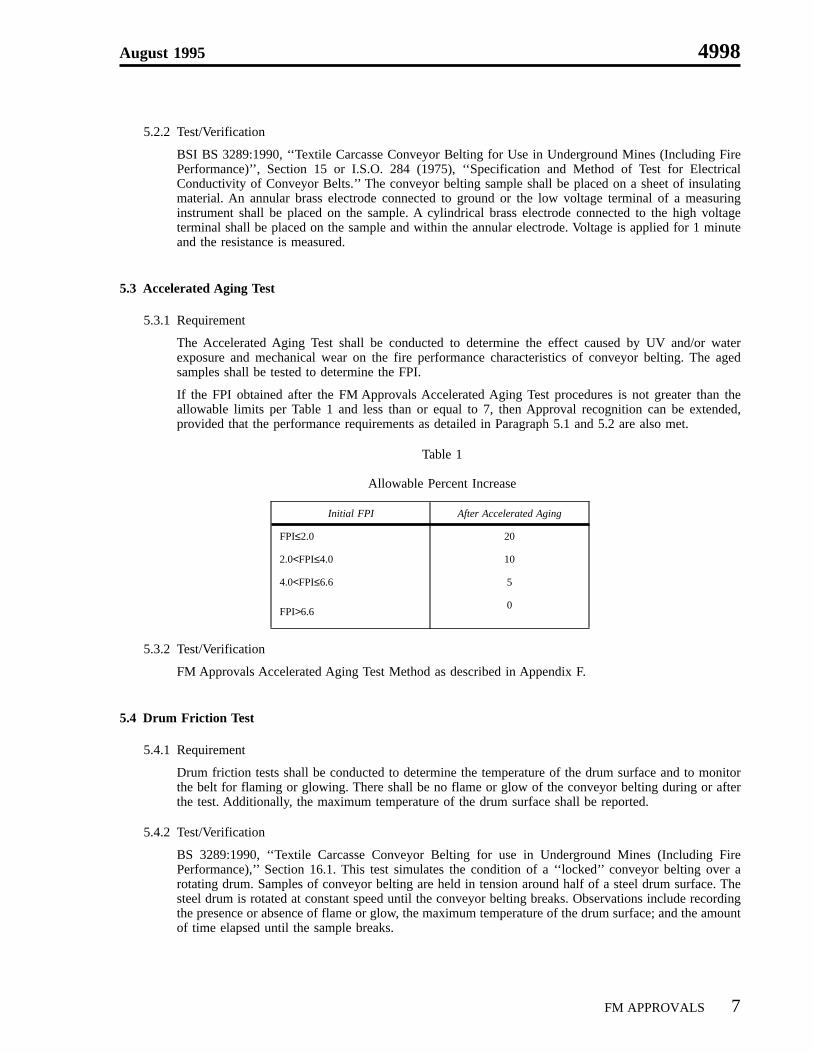
The Accelerated Aging Test shall be conducted to determine the effect caused by UV and/or waterexposure and mechanical wear on the fire performance characteristics of conveyor belting. The agedsamples shall be tested to determine the FPI.
If the FPI obtained after the FM Approvals Accelerated Aging Test procedures is not greater than theallowable limits per Table 1 and less than or equal to 7, then Approval recognition can be extended,provided that the performance requirements as detailed in Paragraph 5.1 and 5.2 are also met.
Table 1
Allowable Percent Increase
Initial FPI After Accelerated Aging
FPI≤2.0 20
2.0<FPI≤4.0 10
4.0<FPI≤6.6 5
FPI>6.60
5.3.2 Test/Verification
FM Approvals Accelerated Aging Test Method as described in Appendix F.
5.4 Drum Friction Test
5.4.1 Requirement
Drum friction tests shall be conducted to determine the temperature of the drum surface and to monitorthe belt for flaming or glowing. There shall be no flame or glow of the conveyor belting during or afterthe test. Additionally, the maximum temperature of the drum surface shall be reported.
5.4.2 Test/Verification
BS 3289:1990, ‘‘Textile Carcasse Conveyor Belting for use in Underground Mines (Including FirePerformance),’’ Section 16.1. This test simulates the condition of a ‘‘locked’’ conveyor belting over arotating drum. Samples of conveyor belting are held in tension around half of a steel drum surface. Thesteel drum is rotated at constant speed until the conveyor belting breaks. Observations include recordingthe presence or absence of flame or glow, the maximum temperature of the drum surface; and the amountof time elapsed until the sample breaks.
August 1995 4998
FM APPROVALS 7
VI OPERATIONS REQUIREMENTS
6.1 Demonstrated Quality Control Program
6.1.1 A Quality Control Program is required to assure that each subsequent length of conveyor belting producedby the manufacturer shall present the same quality and reliability as the specific samples examined. Designquality, conformance to design, and performance are the areas of primary concern.
Design quality is determined during the examination and tests.
Conformance to design is verified by control of quality in the following areas:
• existence of corporate quality control guidelines
• incoming assurance, including test
• in-process assurance, including test
• final inspection and test
• field installation procedures
• equipment calibration
• drawing and change control
• packaging and shipping
• handling nonconforming materials.
Quality of performance is determined by field performance and by re-examination and test.
6.1.2 The manufacturer shall establish a system of product configuration control to prevent unauthorizedchanges, including, as appropriate:
• engineering drawings
• engineering change requests
• engineering orders
• change notices
These shall be executed in conformance with a written policy and detailed procedures. Records of allrevisions to all Approved products shall be kept.
6.1.3 The manufacturer shall assign an appropriate person or group to be responsible for obtainingFM Approvals authorization of all changes anticipated to Approved products. FM Approvals Form 797,‘‘Approved Product Revision Report or Address/Contact Change Notice’’, is provided to notifyFM Approvals of pending changes. Any such changes shall be submitted prior to fabrication and/ordistribution, and shall be agreed to in writing by FM Approvals.
4998 August 1995
8 FM APPROVALS
6.2 Facilities and Procedures Audit (F&PA)
6.2.1 An inspection of the product manufacturing facility shall be part of the Approval investigation. Its purposeshall be to determine that the raw materials, formulation, equipment, products, and the manufacturer’scontrols are properly maintained to produce a product of the same quality, construction and formulationas initially tested.
6.2.2 Unannounced follow-up inspections shall be conducted to assure continued quality control and productuniformity.
August 1995 4998
FM APPROVALS 9
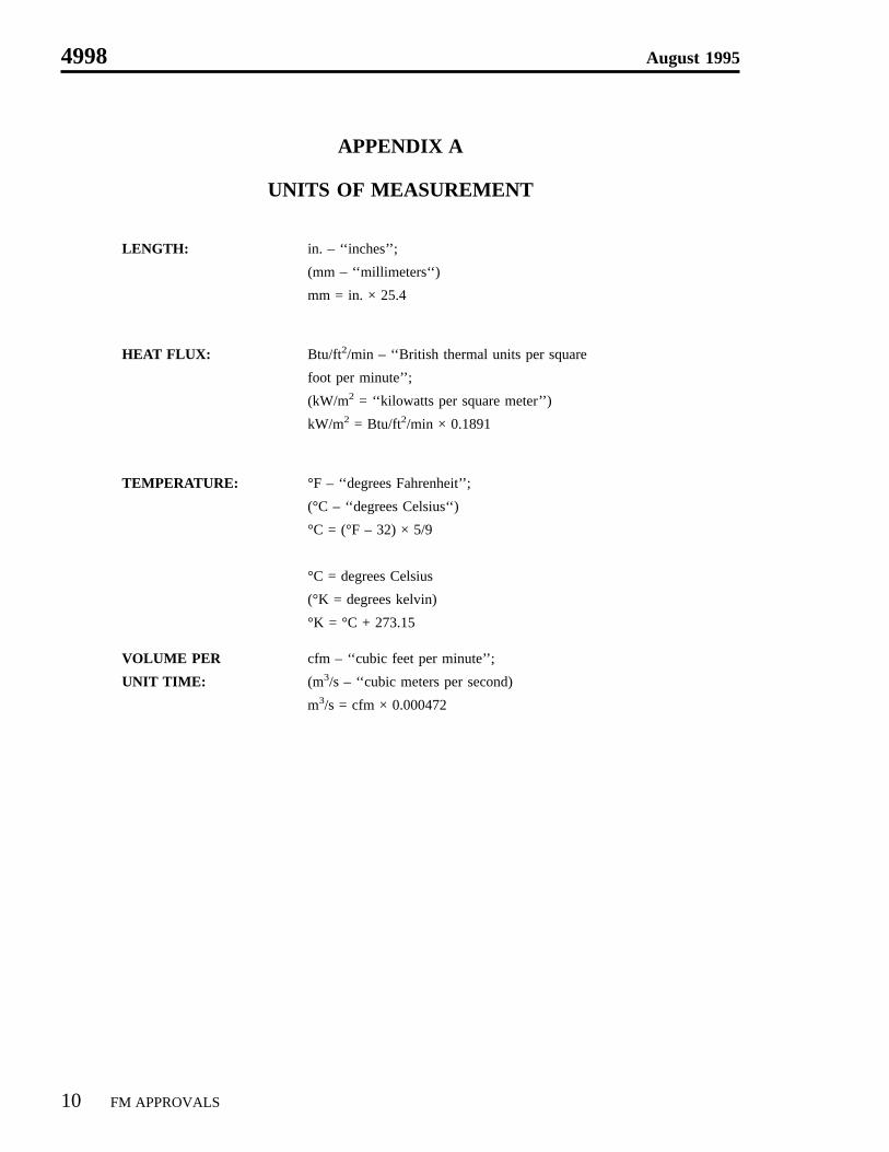
APPENDIX A
UNITS OF MEASUREMENT
LENGTH: in. – ‘‘inches’’;
(mm – ‘‘millimeters‘‘)
mm = in. × 25.4
HEAT FLUX: Btu/ft2/min – ‘‘British thermal units per square
foot per minute’’;
(kW/m2 = ‘‘kilowatts per square meter’’)
kW/m2 = Btu/ft2/min × 0.1891
TEMPERATURE: °F – ‘‘degrees Fahrenheit’’;
(°C – ‘‘degrees Celsius‘‘)
°C = (°F – 32) × 5/9
°C = degrees Celsius
(°K = degrees kelvin)
°K = °C + 273.15
VOLUME PER
UNIT TIME:
cfm – ‘‘cubic feet per minute’’;
(m3/s – ‘‘cubic meters per second)
m3/s = cfm × 0.000472
4998 August 1995
10 FM APPROVALS
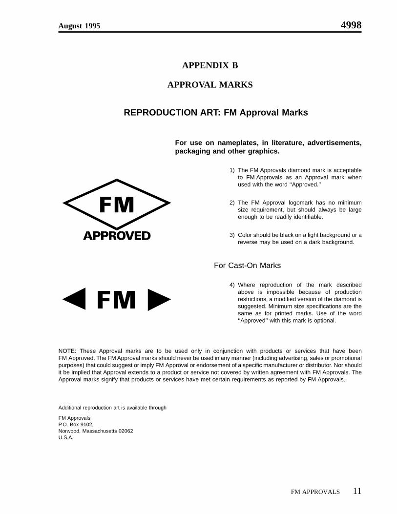
APPENDIX B
APPROVAL MARKS
REPRODUCTION ART: FM Approval Marks
For use on nameplates, in literature, advertisements,packaging and other graphics.
1) The FM Approvals diamond mark is acceptableto FM Approvals as an Approval mark whenused with the word ‘‘Approved.’’
2) The FM Approval logomark has no minimumsize requirement, but should always be largeenough to be readily identifiable.
3) Color should be black on a light background or areverse may be used on a dark background.
For Cast-On Marks
4) Where reproduction of the mark describedabove is impossible because of productionrestrictions, a modified version of the diamond issuggested. Minimum size specifications are thesame as for printed marks. Use of the word‘‘Approved’’ with this mark is optional.
NOTE: These Approval marks are to be used only in conjunction with products or services that have beenFM Approved. The FM Approval marks should never be used in any manner (including advertising, sales or promotionalpurposes) that could suggest or imply FM Approval or endorsement of a specific manufacturer or distributor. Nor shouldit be implied that Approval extends to a product or service not covered by written agreement with FM Approvals. TheApproval marks signify that products or services have met certain requirements as reported by FM Approvals.
Additional reproduction art is available through
FM ApprovalsP.O. Box 9102,Norwood, Massachusetts 02062U.S.A.
August 1995 4998
FM APPROVALS 11
APPENDIX C
DETERMINATION OF THE FIRE PROPAGATION INDEX (FPI)
C-1 Introduction
The test method utilized in this standard is based on a quantitative numerical value called the Fire PropagationIndex (FPI). It is assigned to a material based on ignition and heat release properties as measured in a testapparatus. Using advanced calorimetry testing technology, this test method has been developed which has anexcellent correlation to existing full-scale test methods, such as the U.S. Bureau of Mines (USBM) Large-ScaleFire Galley, used to determine the flame propagation characteristics of conveyor belting.
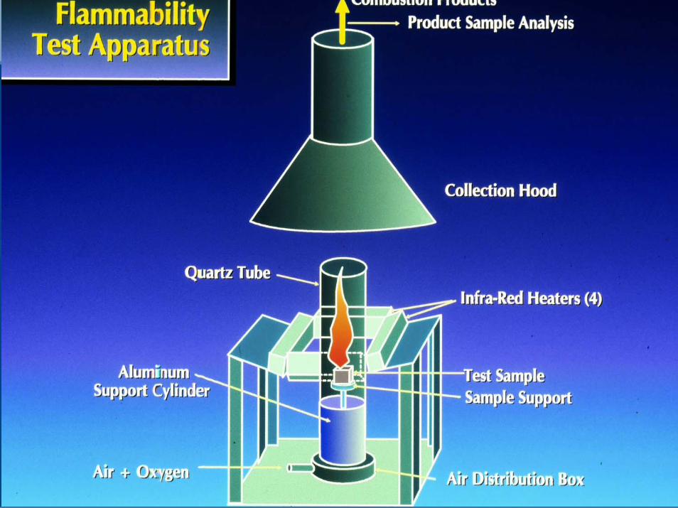
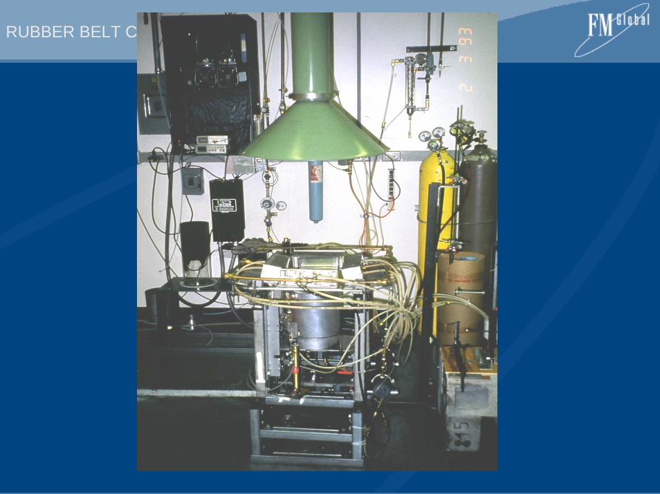
In order to determine the FPI for a material, it is necessary to conduct two tests using the FM Approvals 50 kWFlammability Apparatus (See Appendix D, Figure D-1). The first test is the Piloted Ignition Test. The second testis the Fire Propagation Test (See Appendices D and E, respectively, for details of these test methods).
C-2 Piloted Ignition Test
C-2.1 For details of the Piloted Ignition Test method, see Appendix D.
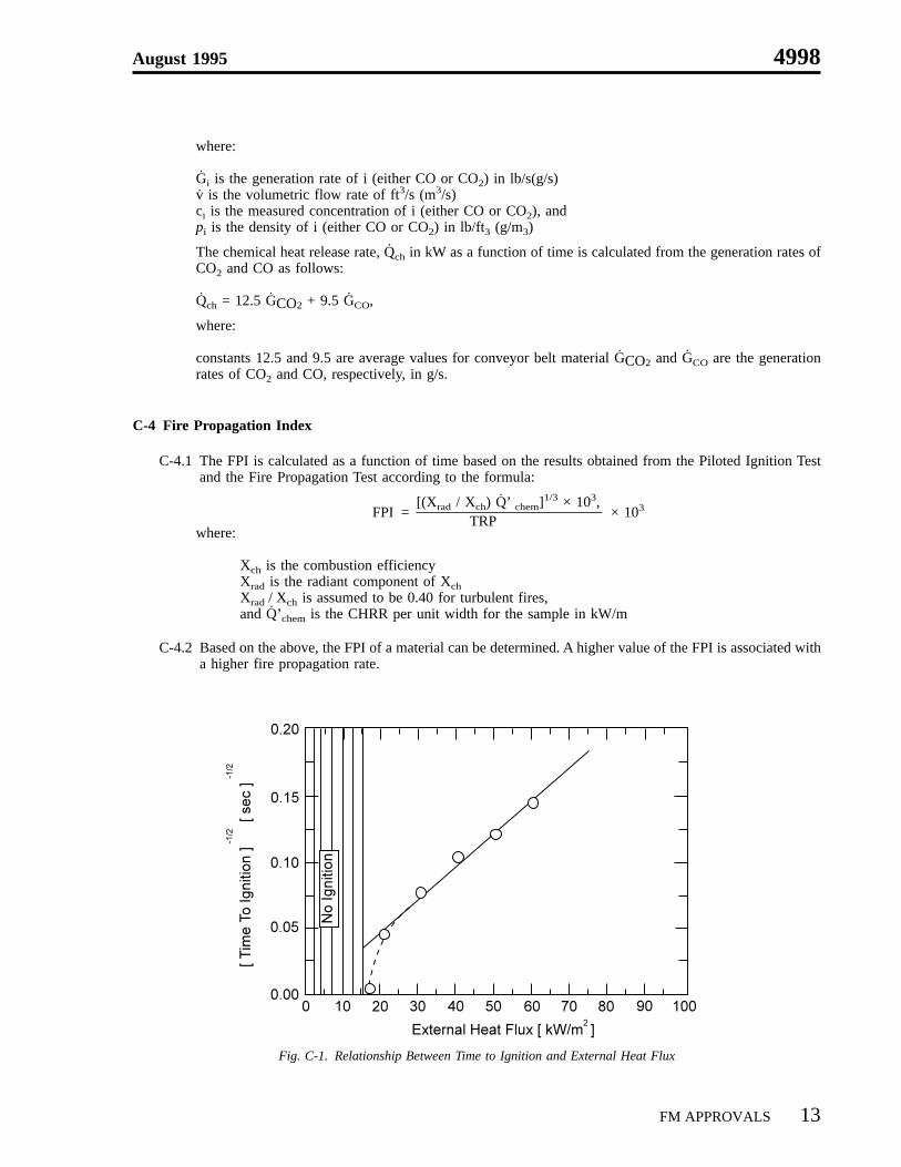
C-2.2 In the Piloted Ignition Test, conveyor belt samples are exposed to a different external radiant heat flux.The heat flux values and the time to ignition, tig, are recorded for each sample. The relationship betweeneach external radiant heat flux and the inverse of the square root of time to ignition is then plotted ingraphical form (Figure C-1).
A regression analysis is performed on the linear portion of the inverse slope of the curve to obtain theThermal Response Parameter (TRP) of the conveyor belting. This can be expressed as:
TRP = ∆tig (kpc)1/2, where:
∆tig is the ignition temperature rise above the sample surface temperature of K,k is the thermal conductivity, Btu × ft/(h × ft2 × °F)(kW/m-k) of the sample,p is the density, lbs/ft3 (kg/m3) of the sample,and c is the specific heat, cal/g- °C(kJ/kg-k) of the sample.
C-3 Fire Propagation Test
C-3.1 For details of the Fire Propagation Test method, see Appendix E.
C-3.2 In the Fire Propagation Test, all fire products, along with the ambient air, are captured in the samplingduct. In the duct is a measurement section where concentrations of CO (carbon monoxide) and CO2(carbon dioxide), total volumetric flow, gas temperatures and ambient temperatures, are measured as afunction of time.
Based on the measurements of the generation rates of CO and CO2, the Chemical Heat Release Rate(CHRR) of the material, Qchem, as a function of time can be computed using a formula:
Gi = vcipi
4998 August 1995
12 FM APPROVALS
where:
Gi is the generation rate of i (either CO or CO2) in lb/s(g/s)v is the volumetric flow rate of ft3/s (m3/s)ci is the measured concentration of i (either CO or CO2), andpi is the density of i (either CO or CO2) in lb/ft3 (g/m3)
The chemical heat release rate, Qch in kW as a function of time is calculated from the generation rates ofCO2 and CO as follows:
Qch = 12.5 GCO2 + 9.5 GCO,
where:
constants 12.5 and 9.5 are average values for conveyor belt material GCO2 and GCO are the generationrates of CO2 and CO, respectively, in g/s.
C-4 Fire Propagation Index
C-4.1 The FPI is calculated as a function of time based on the results obtained from the Piloted Ignition Testand the Fire Propagation Test according to the formula:
[(Xrad / Xch) Q’ chem]1/3 × 103,FPI = × 103
TRPwhere:
Xch is the combustion efficiencyXrad is the radiant component of XchXrad / Xch is assumed to be 0.40 for turbulent fires,and Q’chem is the CHRR per unit width for the sample in kW/m
C-4.2 Based on the above, the FPI of a material can be determined. A higher value of the FPI is associated witha higher fire propagation rate.
Fig. C-1. Relationship Between Time to Ignition and External Heat Flux
August 1995 4998
FM APPROVALS 13
APPENDIX D
PILOTED IGNITION TEST METHOD
D-1 Introduction
The Piloted Ignition Test method is used to determine the TRP of conveyor belting materials for the evaluationof fire propagation behavior.
D-2 Test Apparatus
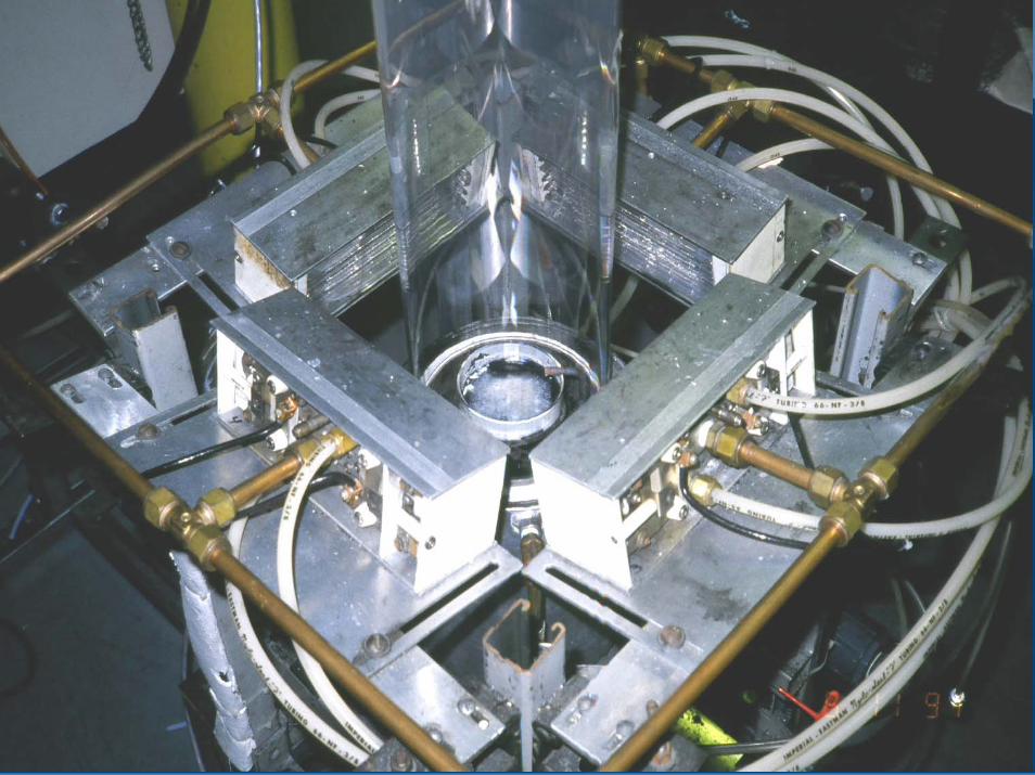
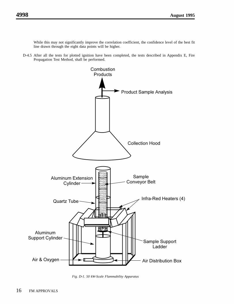
D-2.1 The Piloted Ignition Test is conducted using the FM Approvals 50 kW Flammability Apparatus as shownin Figures D-1 and D-2. Figure D-1 shows an overall sketch of the apparatus whereas Figure D-2 showsthe lower part of the apparatus used for the Piloted Ignition Test.
D-2.2 For this testing, a conveyor belt sample, 3 in. × 3 in. (76 mm × 76 mm), is placed on the sampleholder/platform of the test apparatus. Prior to placement in the apparatus, the sample is coated with carbonblack. The sample is surrounded by four high density tungsten-quartz radiant heaters. The radiant heatersare used to expose the sample to various external heat fluxes. The combustible vapors that are generated,as a result of the external heat flux, are ignited with a pilot flame.
The pilot flame, adjusted to provide a blue-white flame, consists of a horizontal premixed ethylene-airflame, established at the ceramic tip of a 0.25 in. (6 mm) diameter metallic tube, attached to ethylene andair cylinders. The pilot flame is about 0.4 in. (10 mm) long and is located within 0.4 (10 mm) of theconveyor belting surface.
D-3 Test Procedure
D-3.1 Conveyor belt samples, supplied by the manufacturer, shall be prepared and cleaned. Each sample shallbe 3 in. × 3 in. (76 mm × 76 mm), and thoroughly cleaned using a warm, soapy solution to remove allsurface deposits, film or residue that may impact ignition. Any oil, grease or other residue remaining onthe surface shall be removed by use of methyl, ethyl or isopropyl alcohol. The surface shall be towel-driedand allowed to stand at room temperature until completely dry.
D-3.2 The cleaned surface of the conveyor belting shall be lightly coated with carbon black.
D-3.3 The sample is then placed on the holder/platform which is positioned such that the height of the centerlineof the sample is located at the point of maximum heat flux intensity.
D-3.4 The pilot flame, adjusted by the flow of ethylene and air, shall be 0.4 in. (10 mm) long and placed within0.4 in. (10 mm) of the surface of the conveyor belting material.
D-3.5 The water-cooled radiant heater shield shall be raised and power to the radiant heater turned on. Thevoltage shall be increased to produce the initial test setting of 158 Btu/ft2/min (30 kW/m2). After oneminute, the shield shall be lowered and a stopwatch shall be started. The elapsed time on the stopwatchshall be defined as time to ignition, tig.
D-3.5.1 A split stopwatch shall be used to record flash (entire sample ignites briefly, but fails to supportcombustion) time(s) as well as sustained ignition time. The sustained ignition time shall bedesignated as the ‘‘time to ignition’’.
4998 August 1995
14 FM APPROVALS
D-3.5.2 An individual test shall be terminated if the sample fails to ignite after 15 minutes. In this case,the test results shall be recorded as ‘‘No Ignition’’.
D-3.6 The above procedure shall be repeated for each of the radiant heater test sequences shown in Table D-1.The measured data for time to ignition, tig, and the corresponding external heat flux, shall be recorded foreach sample.
If the piloted ignition data is graphically plotted and exhibits clear curvilinear behavior between the heatfluxes of 158 to 211 Btu/ft2/min (30 to 40 kW/m2) as shown in Table D-1, Test Sequence 1 data point shallbe discarded and Test Sequence 5 added. The heat flux of Test Sequence 5 shall be either 238 to291 Btu/ft2/min (45 to 55 kW/m2).
Table D-1
Radiant Heater Test Sequence for Ignition Testing Heat Flux
Test Sequence Btu/ft2/min (kW/m2)
1 158 (30)
2 211 (40)
3 264 (50)
4 317 (60)
D-4 Test Results
D-4.1 The values for each incremental external heat flux and the corresponding inverse of the square root of thetime to ignition, tig
-1/2, shall be plotted on the x-axis and y-axis, respectively.
D-4.2 The TRP shall be determined from the inverse of the slope of the best fitted line formed from the above,using the least-mean square procedure. A regression analysis of the data shall be performed and shallresult in a least-mean square correlation coefficient of at least 0.996. This will assure a maximum 5% errorin determining the TRP.
D-4.2.1 When ignition occurs at all heat fluxes, but the correlation coefficient is determined to be less than0.996, the data shall be plotted as shown in Appendix C, Figure C-1.
D-4.2.2 If the plot clearly indicates that the 158 Btu/ft2/min (30kW/m2) data point is outside the linearrange, it shall be discarded and a substitute ignition test conducted at a heat flux of either 238 or291 Btu/ft2/min (45 or 55 kW/m2).
D-4.2.3 If the resulting correlation coefficient of these four points is less than 0.996, four additionalpiloted ignition tests at the heat fluxes normally selected between 211 and 317 Btu/ft2/min (40 and60 kW/m2) shall be conducted.
D-4.2.4 If the ignition plot does not suggest curvilinear behavior at the 158 Btu/ft2/min (30 kW/m2) heatflux, four additional ignition tests shall be performed at different heat flux settings.
D-4.3 If ignition of the test sample does not occur at 158 Btu/ft2/min (30 kW/m2) after a full 15 minutes, andthe correlation coefficient for the remaining three points is greater than or equal to 0.996, the TRP shallbe determined from these three points. If the correlation coefficient is less than 0.996, five additionalignition tests shall be conducted at elevated heat fluxes.
D-4.4 If the test samples fail to ignite at both 158 and 211 Btu/ft2/min (30 and 40 kW/m2), six additional ignitiontests shall be conducted with the heat fluxes selected so that the eight total data points are distributed withthree each at 317 and 291 Btu/ft2/min (60 and 55 kW/m2) and the remaining two points at 264 Btu/ft2/min(50 kW/m2).
August 1995 4998
FM APPROVALS 15
While this may not significantly improve the correlation coefficient, the confidence level of the best fitline drawn through the eight data points will be higher.
D-4.5 After all the tests for plotted ignition have been completed, the tests described in Appendix E, FirePropagation Test Method, shall be performed.
Fig. D-1. 50 kW-Scale Flammability Apparatus
4998 August 1995
16 FM APPROVALS
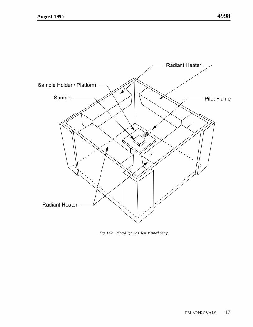
Fig. D-2. Piloted Ignition Test Method Setup
August 1995 4998
FM APPROVALS 17
APPENDIX E
FIRE PROPAGATION TEST METHOD
E-1 Introduction
The Fire Propagation Test method is used to obtain the generation rates of CO (carbon monoxide) and CO2(carbon dioxide). These values are needed to determine the Chemical Heat Release Rate (CHRR) for evaluatingthe fire propagation behavior and to determine the Fire Propagation Index.
E-2 Test Apparatus
E-2.1 The Fire Propagation Test is conducted using the FM Approvals 50kW Flammability Apparatus as shownin Appendix D, Figure D-1, which shows the lower part of the Apparatus where the conveyor beltingsample is placed for fire propagation testing.
E-2.2 For this testing, a conveyor belt sample 3 in. wide by 12 in. long (76 mm × 305 mm) is required. Heavyduty aluminum foil is used to cover the back and ceramic paper is used to cover the edges of the sample,leaving only the front face exposed. The sample is surrounded by a quartz or Pyrex tube, 12 in. (305 mm)in diameter and approximately 24 in. (610 mm) in length. Placed on top of the quartz or Pyrex tube is a12 in. (305 mm) diameter aluminum extension tube approximately 24 in. (610 mm) in length which directsall gases and particulates into the collection funnel. Holes 3⁄8 in. (9.5 mm) in diameter are drilled throughthe tube, vertically, for observation purposes.
The sample is placed in the FM Approvals sample holder until it rests upon the base, is centered and thenfastened near the bottom by three set screws in the base of the holder, and held firmly near its upper endby No. 24 gauge nichrome wire attached to the two upright supports. The conveyor belt height is adjustedso that 3 in. (76 mm) above the top edge of the base of the sample holder corresponds to the peak levelof the directed external heat flux.
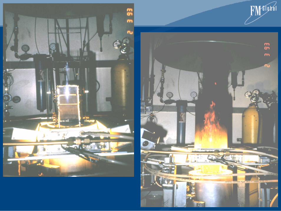
E-2.3 The conveyor belt sample is surrounded by four radiant heaters and the bottom 3 in. (76 mm) of the beltis exposed to 264 Btu/ft2/min (50 kW/m2) of external heat flux. A pilot flame, located 3.5 in. (89 mm)above the bottom end of the sample is used to ignite the combustible vapors.
The pilot flame, adjusted to produce a blue-white flame, consists of a horizontal, premixed ethylene-airflame, established at the ceramic tip of a 0.25 in. (6 mm) diameter metallic tube attached to ethylene andair cylinders. The pilot flame is about 0.4 in. (10 mm) long and is located within 0.4 in. (10 mm) of theconveyor belting surface.
E-2.4 To simulate large-scale flame radiation conditions, air with an oxygen concentration of 40% is introducedat the air distribution chamber inlet and travels upward through the quartz (Pyrex) tube at a flow rate of7 cfm (0.2 m3/min) (see Appendix D, Figure D-1). The oxygen concentration of the air is monitored byan oxygen analyzer and an airflow meter.
E-2.5 The fire products generated during the test are captured in the sampling duct of the Apparatus. Measure-ments are made for the concentrations of CO, CO2, and volumetric flow rate, v
4998 August 1995
18 FM APPROVALS
E-3 Test Procedure
E-3.1 Conveyor belt samples shall be prepared and cleaned. Each sample shall be 3 in. wide by 12 in. long(76 mm × 305 mm) and thoroughly cleaned using warm, soapy solution to remove all surface deposits,film or residue that may impact ignition. Any oil, grease or other residue remaining on the surface shallbe removed by use of methyl, ethyl or isopropyl alcohol. The sample shall be towel-dried and allowed tostand at room temperature until completely dry.
E-3.2 Heavy duty aluminum foil is used to cover the back of the sample and ceramic paper to cover the edgesleaving only the front face exposed. The test sample is then placed, centered and secured, in the testsample holder, both of which are then inserted into the central base of the air distribution chamber.
E-3.3 The exhaust stack blast gate is then opened and the data acquisition system turned on. The pressuretransducer in the exhaust shall be adjusted to zero referenced value. The exhaust blower shall be turnedon. All gas analyzers are calibrated.
E-3.4 The pilot flame shall be lit and the ethylene-air mixture adjusted to produce a flame cone length of 0.4 in.(10 mm). The horizontal flame shall then be directed to within 0.4 in. (10 mm) of the samples outersurface. The quartz (Pyrex) tube shall be placed over the sample. The aluminum extension tube is placedon top of the quartz (Pyrex) tube. The airflow into the bottom of the tube shall be set at 7 cfm(0.2 m3/min.). The oxygen concentrations in the air entering the tube shall be increased to 40% ± 1% byadding a metered concentration of 100% oxygen while maintaining the proper airflow through theApparatus at 7 cfm (0.2 m3/min.).
E-3.5 The computer acquisition system shall be initiated and compile three minutes of background data (ambientconditions). The pilot flame shall be lit and the test sample cooling shield raised. The cooling water supplyfor both the shield and the infrared heaters shall be turned on. The infrared radiant heater’s powercontroller shall be turned on and adjusted to a setting of 264 Btu/ft2/min (50kW/m2), which is to bestabilized within 30 seconds. An additional 30 seconds shall be allowed, but not exceeded, before the startof the test is initiated. This protocol prevents re-radiated heat from affecting the conveyor belt above theprotecting cooling shield.
E-3.6 A stopwatch shall be used to record event times. The cooling shield shall be dropped at 30 seconds.Observation and notes shall be recorded.
E-3.6.1 As the test sample is exposed to the energy produced by the infrared radiant heaters, vapors aregenerated. When they reach a combustible level, they will be ignited by the pilot flame. Followingignition of the test sample, the pilot flame is turned off.
E-3.6.2 During the course of the test, exhaust gases are drawn from the exhaust stack and analyzed. Theconcentration of CO and CO2 are recorded. The volumetric flow rate, v, shall be measured usingthe exhaust stack mounted pilot tube.
E-3.7 The test sample shall be allowed to burn until it self-extinguishes. Data shall continue to be collected foran additional three minutes at which time the test shall be terminated and the radiant heaters andsupplementary oxygen supply turned off. The exhaust blower should be left on to aid cooling of theApparatus.
E-4 Test Results
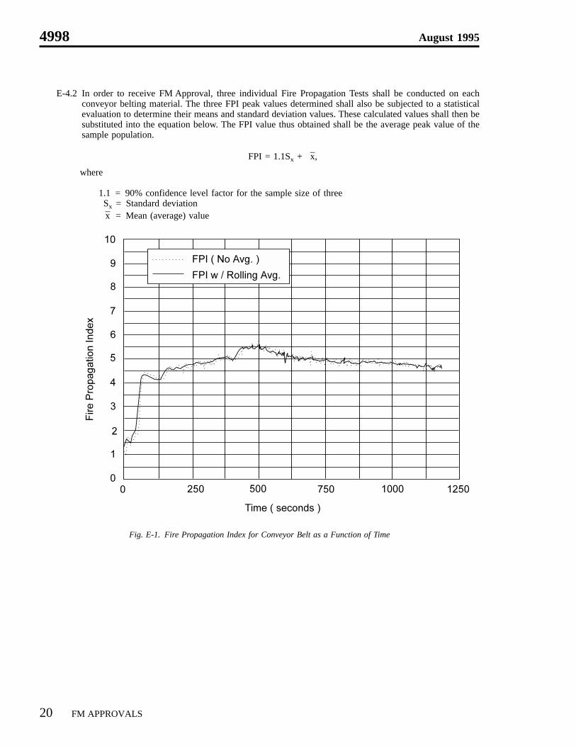
E-4.1 Following completion of the test, the data generated over the length of the test is analyzed by computingthe FPI. Q’ch is calculated from the CO2 and CO generation rates, which are taken at a scan rate of onescan per second. Then using Eq. C-4.1, the FPI is determined for 15 sec. rolling average of Q’ch as afunction of time. The peak FPI is reported.
This averaging is used to prevent nonrepresentative, transient fire spikes from adversely influencing thepeak FPI values that are reported. A sample plot is shown in Figure E-1.
August 1995 4998
FM APPROVALS 19
E-4.2 In order to receive FM Approval, three individual Fire Propagation Tests shall be conducted on eachconveyor belting material. The three FPI peak values determined shall also be subjected to a statisticalevaluation to determine their means and standard deviation values. These calculated values shall then besubstituted into the equation below. The FPI value thus obtained shall be the average peak value of thesample population.
FPI = 1.1Sx + –x,
where
1.1 = 90% confidence level factor for the sample size of threeSx = Standard deviation–x = Mean (average) value
Fig. E-1. Fire Propagation Index for Conveyor Belt as a Function of Time
4998 August 1995
20 FM APPROVALS
APPENDIX F
FM APPROVALSACCELERATED AGING TEST METHOD
F-1 Introduction
The FM Approvals Accelerated Aging Test is intended to simulate the deterioration caused by the ultravioletenergy of sunlight and/or water as rain or dew and mechanical wear. It is not intended to simulate the deterio-ration caused by localized weather phenomena such as atmospheric pollution, biological attach, or saltwaterexposure.
This test procedure includes the FM Approvals Accelerated Wear Test procedures, optional FM ApprovalsAccelerated Weathering Test procedures, and Flammability Characterization.
F-2 Sequence of Testing
F-2.1 All conveyor belting shall first be aged by mechanical wear. Mechanical wear shall be simulated by theFM Approvals Accelerated Wear Test procedures.
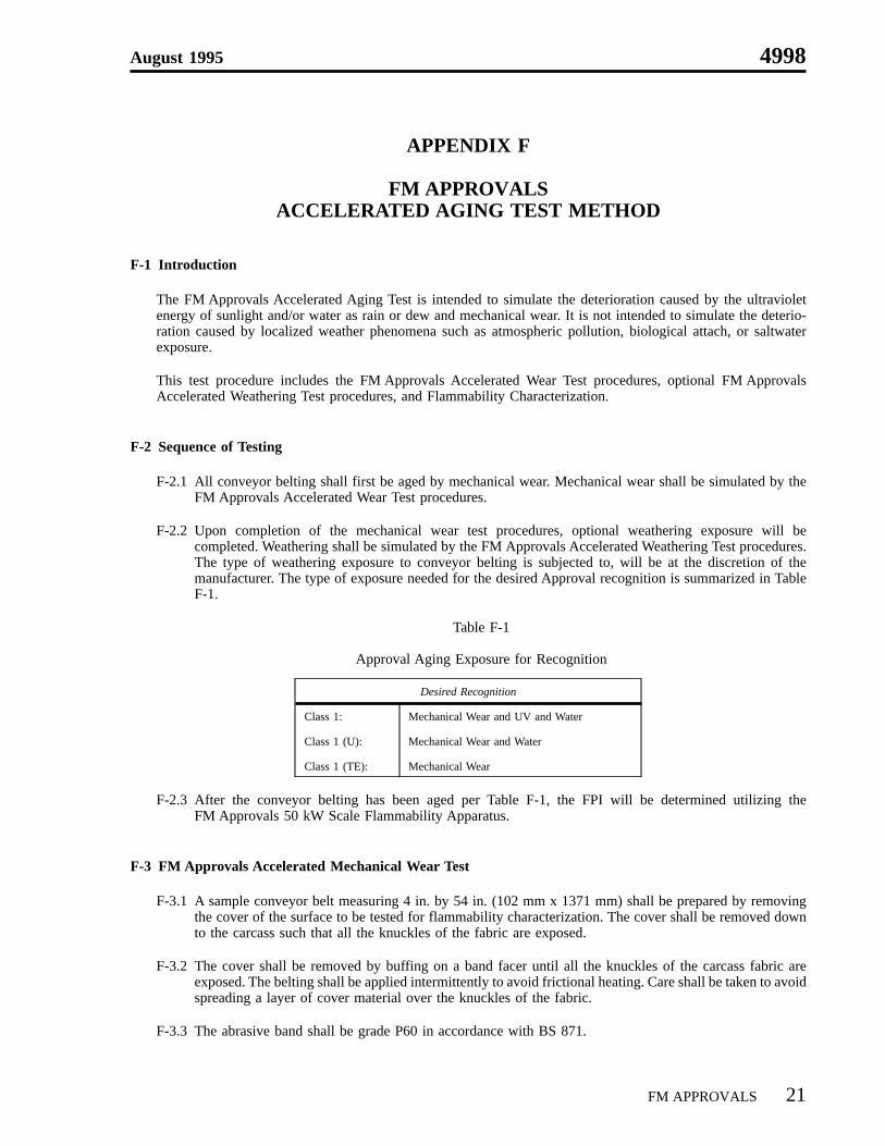
F-2.2 Upon completion of the mechanical wear test procedures, optional weathering exposure will becompleted. Weathering shall be simulated by the FM Approvals Accelerated Weathering Test procedures.The type of weathering exposure to conveyor belting is subjected to, will be at the discretion of themanufacturer. The type of exposure needed for the desired Approval recognition is summarized in TableF-1.
Table F-1
Approval Aging Exposure for Recognition
Desired Recognition
Class 1: Mechanical Wear and UV and Water
Class 1 (U): Mechanical Wear and Water
Class 1 (TE): Mechanical Wear
F-2.3 After the conveyor belting has been aged per Table F-1, the FPI will be determined utilizing theFM Approvals 50 kW Scale Flammability Apparatus.
F-3 FM Approvals Accelerated Mechanical Wear Test
F-3.1 A sample conveyor belt measuring 4 in. by 54 in. (102 mm x 1371 mm) shall be prepared by removingthe cover of the surface to be tested for flammability characterization. The cover shall be removed downto the carcass such that all the knuckles of the fabric are exposed.
F-3.2 The cover shall be removed by buffing on a band facer until all the knuckles of the carcass fabric areexposed. The belting shall be applied intermittently to avoid frictional heating. Care shall be taken to avoidspreading a layer of cover material over the knuckles of the fabric.
F-3.3 The abrasive band shall be grade P60 in accordance with BS 871.
August 1995 4998
FM APPROVALS 21
F-4 FM Approvals Accelerated Weathering Test
The FM Approvals Accelerated Weathering Test shall be conducted in accordance with ASTM G 53 ‘‘StandardPractice for Operating Light- and Water-Exposure Apparatus (Fluorescent UV-Condensation Type) for Exposureof Nonmetallic Materials.’’ The exposure cycles shall be as follows:
F-4.1 (A) For UV and water exposure tests the samples shall be placed in the test apparatus and conditioned for6 weeks (1008 hours). The cycle time shall be 8 hours UV at 140°F ± 5°F (50°C ± 3°C). The UVsource shall be UV-B lamps with a peak emission of 313 nm.
F-4.2 (B) For water exposure tests, the samples shall be placed in the test apparatus and conditioned for 2 weeks(336 hours), during which time the sample will be continuously exposed to condensation at 122°F± 5°F (50°C ± 3°C).
F-5 Flammability Characterization
The FPI of the aged samples shall be determined by using the FM Approvals 50kW Scale FlammabilityApparatus as described in Appendices C, D and E.
4998 August 1995
22 FM APPROVALS