Embed Size (px)
Citation preview

CLOSE
OPEN
MANUAL
AUTO
MINI BALL SCREW POWER DRIVE
OPERATORS MANUAL
Read This Entire Manual Prior To Installation. This Manual Must Be Given To
And Reviewed By The Grower After The Unit Has Been Installed. This Manual
Should Be Kept In A Safe, Readily Accessible Place For Quick Reference.
Agri Ventilation Systems, LLC Dayton, Virginia 22821
1-800-526-4188 JANUARY 2010

2
GENERAL INFORMATION
Power Requirements
The Mini Ball Screw Power Drive is equipped with a 110/120 VAC Gearmotor. The external Controller must supply 110/120 VAC for the control circuit connections in the Mini Ball Screw.
Model Designation Rated Length Total Travel Motor Speed Rate of Travel
BD-AN-1813 18 Inches 15 Inches 107 rpm 21 inches per minute
BD-AO-1813 18 Inches 15 Inches 40 rpm 8 inches per minute
BD-AN-4013 4 Feet 44 Inches 107 rpm 21 inches per minute
BD-AO-4013 4 Feet 44 Inches 40 rpm 8 inches per minute
Dimensions: Length Length Model Without Pulleys With Pulleys Width Depth 1813 39” 48” 9” 6” 4013 69” 77” 9” 6”
INSTALLATION The AVS Mini Ball Screw is designed to handle 2000 pounds of inlet doors or curtains. Typically it can handle both sides of inlets for a static pressure house, or both sides of a tunnel curtain. For larger loads such as sidewall curtains for natural ventilation or panels the installer must determine their weight and design accordingly. The Mini Ball Screw can be mounted horizontally or vertically, on a side or end wall or on the ceiling. There is no one installation procedure due to the flexibility of the Mini Ball Screw and the variations of inlet types. The mounting diagrams in this manual are for illustration purposes only. Though actual installations may vary, they should still follow the general guidelines noted here. Double-back winching is not needed or recommended. Mount the Mini Ball Screw Case to a 2”x10” pressure treated board of appropriate length. There are pre-drilled holes in the back of the case to accommodate this mounting. It is possible to mount the case directly to joists. Drill ½” holes to accommodate different locations for mounting the drive unit. DO NOT DRILL HOLES along the Travel Path of the Pull Bar Guides. The following pages show illustrations for mounting the Mini Ball Screw. Be sure that the load on the chains coming out of the Ball Screw are evenly distributed; uneven loading will cause binding of the Ball Nut and excessive wear of the Ball Screw shaft. Periodically check cabling and pulleys for alignment and operation.

3
Ceiling Mounted Mini Ball Screw for Inlets or Tunnel Curtains Both Sides of House - 1 to 1 Cable Ratio with Hand Winches
Ceiling Mounted Mini Ball Screw for Tunnel Curtains Both Sides of House - 1 to 2 Cable Ratio with Hand Winches
(DO NOT USE FOR INLET BOARDS)

4
End Wall Mounted Mini Ball Screw for Inlets or Tunnel Curtains Both Sides of House - 1 to 1 Cable Ratio with Hand Winches
End Wall Mounted Mini Ball Screw for Tunnel Curtains Both Sides of House - 1 to 2 Cable Ratio with Hand Winches
(DO NOT USE FOR INLET BOARDS)

5
LIMIT SWITCH CAM OPERATION
As shown on the Control Rod Assembly (p.11), the Limit Switch Rod has a white nylon Cam on the end. This Cam moves back and forth in the Cam Bracket (see Electric Plate Assembly, p.15) and activates one of the three limit switches. This is illustrated in the diagrams below.
COMNO
NC
COMNO
NC
COMNO
NC
FAIL SAFE
CLOSEOPEN
The two limit switches on the lower or far side of the cam rod are the Primary switches. They should be at the edges of the lower portion of the cam rod. The third switch on the upper or near side is the Fail-Safe switch. It should be midway between the higher portions of the cam rod. This switch will not activate when the Power Drive is functioning normally. The Fail Safe switch will activate when either Primary limit switch fails, or if the Motor Brake does not stop the motor when the Pull Bar reaches the set collar limit stops. Both of these conditions will require servicing to restore proper operation.
When the Pull Bar Guide hits the Open or Close Limit Set Collar (#7 on Control Rod Assembly, p.11), it pushes the Control Rod which in turn moves the nylon Cam and it activates the corresponding Limit Switch to stop the Motor and activate the Motor Brake.
Check the operation of the limit switches when installing. The limit switches are located in the motor compartment of the Ball Screw case, on the Electrical Plate. Changes in adjustment may have occurred due to shipping and handling. All limit switch arms should contact the lower portion of the plastic cam rod (see the illustration below) when the drive unit is between its end stops. The plastic cam may be adjusted by rotating it “up” or “down” the ¼ inch steel Control Rod using pliers. Check limit switch activation (“clicking” of the switch) by moving the Control Rod back and forth by hand. The limit switches should click when each switch lever arm is approximately halfway up or down the transition between the upper and lower portions of the plastic cam rod. It may be necessary to bend the limit switch lever arm to make adequate contact on the cam rod.
This figure shows the Open Limit Switch being activated when the Pull Bar reaches the Open Set Collar.
COMNO
NC
COMNO
NC
FAIL SAFE
CLOSEOPEN
COMNO
NC
Open Motion
6
COMNO
NC
COMNO
NC
FAIL SAFE
CLOSEOPEN
COMNO
NC
Close Motion
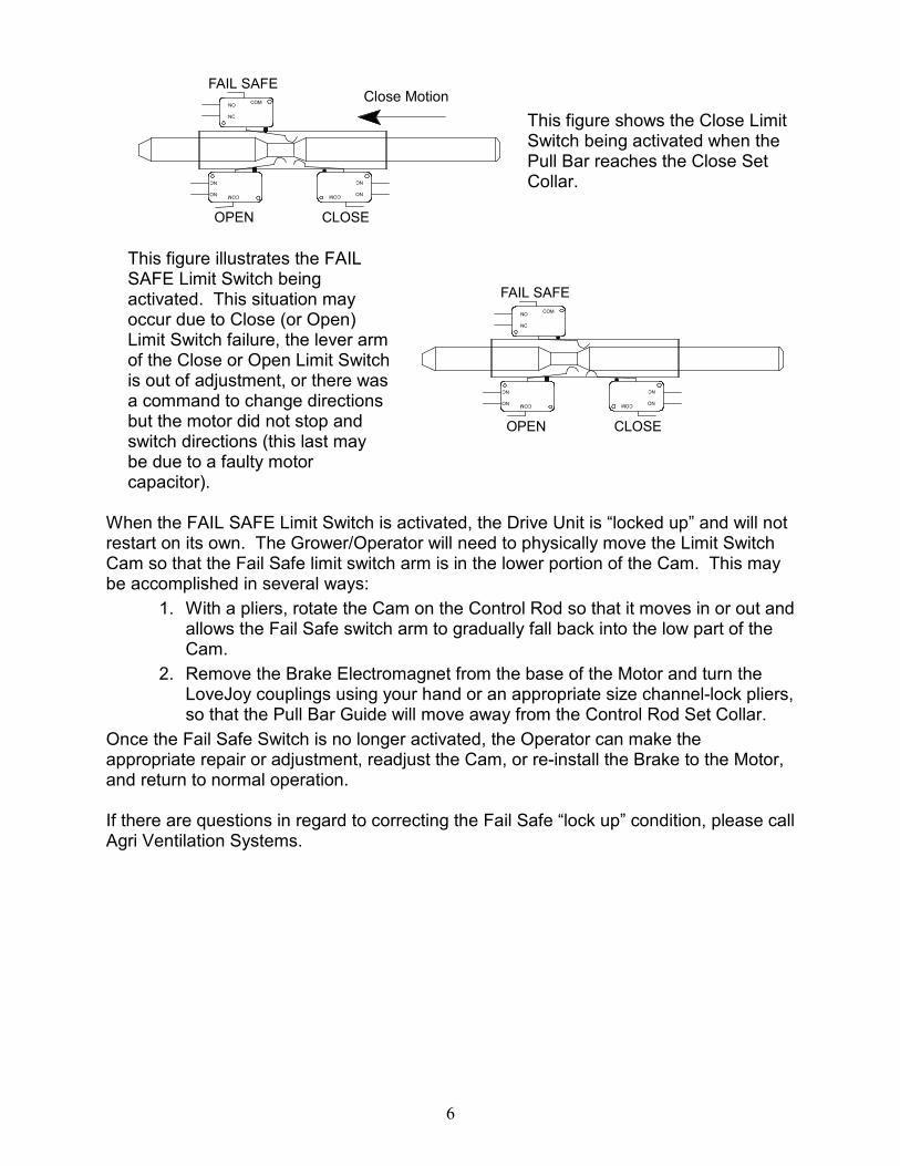
This figure shows the Close Limit Switch being activated when the Pull Bar reaches the Close Set Collar.
This figure illustrates the FAIL SAFE Limit Switch being activated. This situation may occur due to Close (or Open) Limit Switch failure, the lever arm of the Close or Open Limit Switch is out of adjustment, or there was a command to change directions but the motor did not stop and switch directions (this last may be due to a faulty motor capacitor).
COMNO
NC
FAIL SAFE
CLOSEOPEN
COMNO
NC
COMNO
NC
When the FAIL SAFE Limit Switch is activated, the Drive Unit is “locked up” and will not restart on its own. The Grower/Operator will need to physically move the Limit Switch Cam so that the Fail Safe limit switch arm is in the lower portion of the Cam. This may be accomplished in several ways:
1. With a pliers, rotate the Cam on the Control Rod so that it moves in or out and allows the Fail Safe switch arm to gradually fall back into the low part of the Cam.
2. Remove the Brake Electromagnet from the base of the Motor and turn the LoveJoy couplings using your hand or an appropriate size channel-lock pliers, so that the Pull Bar Guide will move away from the Control Rod Set Collar.
Once the Fail Safe Switch is no longer activated, the Operator can make the appropriate repair or adjustment, readjust the Cam, or re-install the Brake to the Motor, and return to normal operation. If there are questions in regard to correcting the Fail Safe “lock up” condition, please call Agri Ventilation Systems.

7
REMOVING AND INSTALLING BALL NUT ASSEMBLY The Ball Screw Shaft must be lubricated regularly for smooth operation. The Ball Nut uses ball bearings to transfer the rotating motion of the Shaft to the linear motion of the Ball Nut Assembly. A tube of White Lithium Grease is included with the Ball Screw Unit. Use this to lubricate the Shaft every two months. More frequent grease application is necessary if usage demands it. If the Ball Nut jams up in operation due to lack of grease, dirt buildup, or uneven cable load, ball bearings may pop out, and the Ball Nut may start rubbing (and scoring) the Ball Screw Shaft. To Remove Ball Nut (also refer to Ball Nut Assembly, p.12): 1. Remove chains from the Pull Bar of the Ball Nut Assembly.
2. Take the Sprocket Plate from end of Ball Screw case.
3. Remove Nut and washers from the end of the Ball Screw Shaft.
4. Remove the side guides from the Pull Bar.
5. Loosen allen screws on motor shaft lovejoy coupling and move coupling toward motor so that Ball Screw Shaft can freely rotate.
6. There is a paper Core Tube included with the Ball Screw Drive. It is taped to the inside of the motor compartment. Take the Core Tube and hold it in place against the end of the screw shaft (see illustration). Turn the Ball Screw Shaft by hand so that the Ball Nut Assembly will move off of the Shaft and unto the Core Tube. The Core Tube keeps the ball bearings of the Ball Nut in place.
7. Reverse procedure when installing
replacement Ball Nut.
CORETUBE
BALLNUT
PULL BAR
SCREW SHAFT

8
LUBRICATION
The Ball Screw Shaft must be lubricated regularly for reliable operation of the drive unit. The manufacturer has included a small tube of white lithium grease (AVS Part No. BS-WG-6000) which should be adequate for the first few months of operation.
white lithium
grease
panef
MULTI-P
URPO
SE LU
BRIC
ANT
The operator should apply a small bead of grease on the ball screw shaft every 2 to 3 months. More frequent lubrication may be necessary depending on drive usage. A possible second point of lubrication is the travel path for the Ball Nut/Pull Bar side guides. This would only be necessary if there is excessive noise from the guides rubbing on the Ball Screw case. The chain sprockets (p.10) are permanently lubricated. The operator should visually inspect daily the chains and sprockets, as well as the cables and pulleys for alignment and freedom of movement. The thrust bearing (p.13) is factory lubricated and needs no further lubrication.

9
MINI BALL SCREW ASSEMBLIES
CLOSE
OPEN
MANUAL
AUTO
SECTION 1: SPROCKET PLATE ASSEMBLY
P.10 SECTION 2: CONTROL ROD ASSEMBLY
P.11 SECTION 3: BALLNUT ASSEMBLY
P.12 SECTION 4: COUPLING ASSEMBLY
P.13 SECTION 5: MOTOR BRAKE ASSEMBLY
P.14 SECTION 6: ELECTRIC PLATE ASSEMBLY
P.15-17

10
1
12
SIDE VIEW FRONT VIEW (without "L" Bracket)
2
65
1 5
4 4
3
7 8
911
1013
14
15
SPROCKET PLATE ASSEMBLY
1. Triple Pulley Bracket “C” . . . HW-TR-1001
2. Triple Pulley Bracket “L” . . . HW-TR-1001
3. ½” Jam Nut (2) . . . NT-.500J 4. ½” Flat Washer (6) . . . WA-.500S 5. Idler Sprocket (2) . . . BS-SP-1000 6. ½” x 2” Bolt (2) . . . BT-.500-2G5 7. Sprocket Plate . . . BS-CE-0001 8. 3/8” x 1-½” Bolt (2) . . . BT-.375-1.5G
9. 3/8” Nut (2) . . . NT-.375 10. ¼” x 1-½” Bolt (2) . . . BT-.250-1.5G 11. ¼” Nut (2) . . . NT-.250 12. Pullbar/Race Bushing. . . BS-3001M 13. 5/16” x ¾” Bolt (4) . . . BT-.312-.75G 14. 5/16” Nut (4) . . . NT-.312 15. Ball Screw Case: . . .
18” . . . BS-3011-18M 4’ . . . BS-3011-4M

11
1
10
2
3
4 5 6 7
8
9 7
8
6 5
11
12
CONTROL ROD ASSEMBLY
1. Limit Switch Cam . . . BS-PL-1000 2. Limit Switch Rod . . .
BS-SS-1414 (18”) BS-SS-4014 (4’)
3. Bearing Plate 4. 5/16” Flat Washer . . . WA-.312U 5. Control Rod Spring (2) . . .
BS-SP-7153 6. Cotter Pin (2) . . . CP-.109-.5
7. 3/8” Set Collar (4) . . . HW-LC-1001 8. Thumb Screw – ¼”x ½” (2) . . . TS-.250-.5 9. Pull Bar Guide . . . BS-SGB-L (see Ball Nut Assembly, p.12) 10. Control Rod Bracket . . . 11. 5/16” x ¾” Bolt . . . BT-.312-.75G 12. 5/16” Nut . . . NT-.312

12
TOP VIEW TOP VIEW
FRONT VIEW
1
}
107 4
11 12
13 17
15
14
1815
16 13
12 11
104
2
6
53 3
8
9
BALL NUT ASSEMBLY
1. Pull Bar Guide, Control Rod Side . . . BS-SGB-L
2. Pull Bar Guide, Right Side . . . BS-SGB-R
3. Chain (specify length) . . . BS-CH-0041 4. Chain Connector Link . . . BS-CH-1000 5. Mini Ball Screw Rod . . .
BS-3004-18M (18”) BS-3004-4M (4’)
6. Mini Ball Nut . . . BS-RF-R30A 7. Pull Bar for Mini . . . BS-3003M 8. ½” Washer (4) . . . WA-.500S 9. Lock Nut ½” Stover . . . LN-.500FS
10. ¼” Nut (4) . . . NT-.250 11. ¼” x 1-½” Bolt (4) . . . BT-.250-1.5G 12. 3/8” Nut (4) . . . NT-.375 13. Chain Bolt, 3/8” x 2” (2) . . .
BT-.375-2G5 14. Reducing Washer . . . HW-RW-0012 15. Machine Screw, 10/24 x ½” . . .
MS-1024-.5PH 16. Mini Ball Nut Wiper Washer . . .
BS-RF-000M 17. Stabilizer Pin . . . 18. #8 Flat Washer (4) . . . WA-8

13
1 15
2
3
4
5
6
78 9
93
14
15
14
10
1115
14
12
13
12
15
14
MOTOR COUPLING ASSEMBLY
1. Motor . . . EP-FR-0040 2. Motor Plate . . . 3. ¼” x ½” Bolt (4) . . . BT-.250-.5G2 4. Motor Key . . . 5. 5/8” Lovejoy Coupling . . .
DR-LJ-0058 6. Urethane Spider . . . DR-LJ-000U 7. ½” Lovejoy Coupling w/ Hole and
Tension Pin . . DR-LJ-012R
8. Tension Pin . . . TP-.250-1.75
9. 3/8” x 1-1/2” Bolt . . . BT-.375-1.5G5 10. ½” Thrust Bearing . . . BS-BR-0012 11. Bearing Plate . . . 12. 3/8” Nut . . . NT-.375 13. Mini Ball Screw Rod . . .
BS-3004-18M (18”) BS-3004-4M (4’)
14. 5/16” x ¾” Bolt (4) . . . BT-.312-.75G 15. 5/16” Nut (4) . . . NT-.312

14
2a
2b
4
3
1
MOTOR BRAKE ASSEMBLY
1. Gearmotor . . . BS-FR-0040 2a. Brake Hub (Nut) . . . 2b. Brake Electromagnet . . . BS-BR-0090 3. Retainer Snap Ring . . . BS-SN-1440 4. 8/32” x 3/8” Machine Screw (4) . . . MS-832-,375PHP

15
CLOSE
OPENMANUAL
AUTO
1
11
23
4
6
75
8
4
9
12
13
14
15
3
3
3
11
11
16
17
20
19
18
ELECTRIC PLATE ASSEMBLY
1. Electric Plate . . . 2. Cam Bracket . . . BS-CE-0009 3. 6/32 Nut . . . NT-632 4. 6/32 x 3/8” Machine Screw . . .
MS-632-.375PHP 5. Limit Switch Simulated Roller . . .
EP-SW-10G4 6. 4/40 Nut . . . NT-440 7. 1/8” Spacer . . . EP-SP-0325 8. 4/40 x 1” Machine Screw . . .
MS-440-1PHP 9. Bridge Rectifier . . . BS-BR-1212
10. 11. 6/32 x 3/4” Machine Screw:
MS-632-.750PHP 12. Toggle Switch Bracket: 13. Switch SPDT: EP-SW-1200 14. Switch DPDT: EP-SW-2200 15. Terminal Block: EP-TR-2131 16. Relay Base: EP-RB-2002 17. 120V DPDT Relay: EP-OR-0120 18. Motor Capacitor: EP-CP-0008 19. 14” Wire Tie: EP-WT-014W 20. 150V Surge Suppressor: ET-MV-0150

16
CO
MN
O
NC
CO
MN
O
NC
CO
MN
O
NC
GRN CLO OPN NTL MOTOR BLK RED WHT GRN
CONTROL BRAKE MOTOR
LINE CONNECTIONS
White
White
Red
Black
Red
Black
green
White
Red
Yellow
White
White
Bla
ck
Red
Black
Bla
ck
Bla
ck
Ora
nge
Ye
llow
Bla
ck
Red
Bla
ck
White
Bla
ck
Red
Red
Bla
ck
150 MOV
Black
Red
Bridge
Rectifier
Wiring Diagram 1: Mini Ball Screw Electric Plate

17
CO
MN
O
NC
CO
MN
O
NC
CO
MN
O
NC
OPN CLO GRN CLO OPN NTL MOTOR BLK RED WHT GRN
SGL SGL CONTROL BRAKE MOTOR
LINE CONNECTIONS
White
White
Red
Black
Red
Black
Grn
White
Yellow
White
White
Bla
ck
Red
Black
Bla
ck
Bla
ck
Ora
ng
e
Yello
w
Bla
ck
Red
Bla
ck
White
Bla
ckR
ed
Red
Bla
ck
150 MOV
Black
Red
Bridge
Rectifier
Black
Red
Black
Red
Wiring Diagram 2: Mini Ball Screw Electric Plate
with Limit Switch Feedback

18
LIMITED WARRANTY
If it appears within one year from the date of invoice between the Purchaser and Agri Ventilation Systems, LLC, that any products or component parts do not conform to the specifications and physical descriptions given to the Purchaser, or that such products or component parts do not perform the function for which they were intended, the Purchaser, at their expense, shall return the products or component parts to the Seller, as prescribed in the AVS Return Materials Policy, with a RGA number, and a written report of defects or failed performance. The Seller shall review the report and inspect the items, and shall determine warranty status, and shall authorize, where applicable, either the repair or replacement of any non-conforming, or non-functioning product or component parts. The liability of the Seller to the Purchaser arising out of the supply of, or use of the product or component parts, whether such liability shall arise during the warranty period, shall in no case exceed the amount paid by the Seller in the repair or replacement of non-conforming, or non-functioning product or component parts. Upon the expiration of the warranty period, all liability of the Seller shall terminate.
Any warranty will be terminated if any product or component parts are installed improperly, misused, misapplied, tampered with, abused, modified, or altered without authorization from Agri Ventilation Systems, LLC. Warranty will not apply to defects of failures caused by, or due to Acts of God, or nature.
WARNING: WHEN THE PRODUCT OR COMPONENT PARTS ARE USED IN A
LIFE SUPPORT VENTILATION SYSTEM, WHERE FAILURE COULD RESULT IN LOSS OR INJURY, THE USER SHALL PROVIDE ADEQUATE PERSONAL ATTENTION, BACK-UP VENTILATION, SUPPLEMENTARY NATURAL VENTILATION, OR FAILURE SYSTEMS, ETC., NECESSARY TO CONTROL THE OPERATION, OR ACKNOWLEDGE WILLINGNESS TO ACCEPT THE ASSOCIATED RISKS OF SUCH LOSS OR INJURY.
This equipment is offered for sale specifically on the Purchaser’s acceptance of the above conditions and the manufacturer’s warranty for this equipment. Acceptance, retention, installation, or operation of this equipment by the Purchaser shall be considered as acknowledgment and acceptance of the above conditions.
AGRI VENTILATION SYSTEMS, LLC
P. O. Box 40, Dayton, VA 22821