Embed Size (px)
Citation preview

Technical Data
Mini Circuit Breakers, Fuse Blocks, and Electronic Circuit Protection
Summary of ChangesThis publication contains new and updated information as indicated in the following table.
Additional Resources
These documents contain additional information concerning related products from Rockwell Automation.
You can view or download publications at http://www.rockwellautomation.com/literature/. To order paper copies of technical documentation, contact your local Allen-Bradley distributor or Rockwell Automation sales representative.
Topic Page
1489-M Miniature Circuit Breakers 2
1492-SP Supplementary Protectors 15
1492-D Circuit Breakers 27
188 Regional Circuit Breakers 37
1492-RCD Residual Current Devices 53
1692 Electronic Circuit Protectors 59
1492-MC Circuit Breakers 61
1492-GH/-GS Circuit Breakers 67
1492-FB Fuse Blocks 71
Topic Page
1489-M Ambient Temperature Derating Charts 7
1492-SP Ambient Temperature Derating Charts 17
1492-MCG Ground Sensing Rated Voltage and Interrupting Capacity Circuit Breaker Catalog Numbers 61
Resource Description
Control Circuit and Load Protection Selection Guide, publication 1492-SG122 Provides product selection and technical information.
Industrial Automation Wiring and Grounding Guidelines, publication 1770-4.1 Provides general guidelines for installing a Rockwell Automation industrial system.
Product Certifications website, http://www.ab.com Provides declarations of conformity, certificates, and other certification details.

1489-M Circuit Breakers
Rockwell Automation Publication 1492-TD014B-EN-P — February 20162
1489-M SpecificationsElectrical Ratings
Poles 1, 2, 3
Tripping characteristics C, D
Rated current (In) 0.5...63 A
Rated frequency [f ] 50/60 Hz
Rated insulation voltage Ui per IEC/EN 60664-1250V AC (phase to ground)440V AC (phase to phase)
Overvoltage category III
Pollution degree 3
Data per UL/CSA
Ratedvoltage
AC
1-pole
C Curve0.5...40 A 277V AC
50...63 A 240V AC
D Curve0.5...35 A 277V AC
40...63 A 240V AC
2-, 3-pole
C Curve0.5...40 A 480Y/277V AC
50...63 A 240V AC
D Curve0.5...35 A 480Y/277V AC
40...63 A 240V AC
DC1-pole 48V DC
2-pole 96V DC (2-pole in series)
Rated interrupting capacity per UL 489 10 kA
Reference temperature for tripping characteristics 40 °C
Electrical endurance6,000 operations
(AC and DC); 1 cycle (1s - ON, 9s - OFF)
Data per IEC/EN 60947-2
Rated operationalvoltage (Ue)
1-pole 230V AC
2-, 3-pole 400 V AC
Highest supply orutilization voltage(Umax)
AC1-pole 253/440V AC
2-, 3-pole 440V AC
DC �1-pole 48V DC
2-pole 96V DC
Min. operating voltage 12V AC, 12V DC
Rated ultimate short-circuit breaking capacity (Icu) 15 kA
Rated service short-circuit breaking capacity (Ics)≤40 A: 11.25 kA
>40 A: 7.5 kA
Rated impulse withstand voltage Uimp. (1.2/50μs) 4 kV (test voltage 6.2kV atsea level, 5kV at 2,000m)
Dielectric test voltage 2 kV (50/60Hz, 1 min.)
Reference temperature for tripping characteristics 30 °C
Electrical endurance1 cycle (2s - ON, 13s - OFF, In ≤ 32A), 1 cycle (2s - ON, 28s - OFF,In > 32A)
In < 30A :20,000 ops.(AC)In ≥ 30A:10,000 ops. (AC)
1,000 ops. (DC)
� Self-declared IEC DC ratings.
Mechanical DataHousing Insulation group II, RAL 7035
Indicator window red ON/green OFF
Protection degree per EN 60529 IP20, IP40 in enclosure with cover
Mechanical endurance 20,000 operations
Shock resistance per IEC/EN 60068-2-27 25 g - 2 shocks - 13 ms
Vibration resistance per IEC/EN 60068-2-6 5g - 20 cycles at 5…150…5 Hzwith load 0.8 In
EnvironmentalEnvironmental conditions (damp heat) per IEC/EN60068-2-30
28 cycles with 55°C/90-96% and25°C/95-100%
Ambient temperatureΔ -25…+55 °C
Storage temperature -40…+70 °C
InstallationTerminal Dual terminal
Cross-section of wire ♦ – solid, stranded (front/back terminal slot)
35/35 mm2
18…4/18…10 AWG
Cross-section of wire – flexible (front/back terminal slot) 25/10 mm2
Multi-wire rating per UL, CSA1 wire, 18…4 AWG
2-4 wires‡, 18…10 AWG
Cross-section of bus bars (back terminal slot) 10 mm2
Tightening torque
IEC 2.8 N•m
UL/CSAAWG 18...16: 13.3 in•lb, AWG 14...10: 17.7 in•lb,
AWG 8...4: 39.8 in•lb
Screwdriver No. 2 Pozidrive
MountingDIN Rail (EN 60715, 35 mm)
with fast clip
Mounting position Any
Supply Optional
Approximate Dimensions and Weight
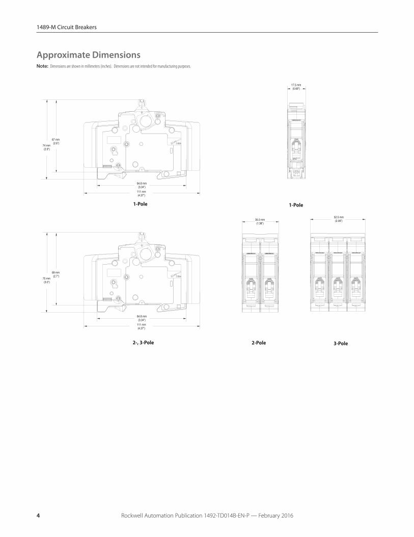
Pole dimensions (H x D x W) 111 x 69 x 17.5 mm (4.37 x 2.72 x .69")
Pole weight 125 g (4.4 oz.)
Combination with Auxiliary ElementsAuxiliary contact Yes
Signal contact Yes
Shunt trip Yes
♦ 35 mm self-declared, not included in IEC/EN approval.
Δ Refer to the ambient temperature derating tables.
‡ Wires must be of like size and stranding. Up to two wires per terminal slot.
1489-M Circuit Breakers
Rockwell Automation Publication 1492-TD014B-EN-P — February 2016 3
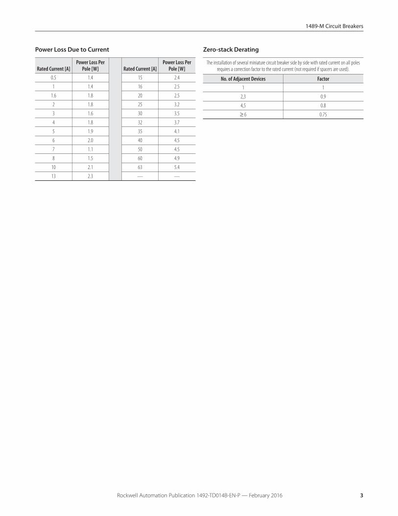
Power Loss Due to Current
Rated Current [A]Power Loss Per
Pole [W] Rated Current [A]Power Loss Per
Pole [W]0.5 1.4 15 2.4
1 1.4 16 2.5
1.6 1.8 20 2.5
2 1.8 25 3.2
3 1.6 30 3.5
4 1.8 32 3.7
5 1.9 35 4.1
6 2.0 40 4.5
7 1.1 50 4.5
8 1.5 60 4.9
10 2.1 63 5.4
13 2.3 — —
Zero-stack Derating
The installation of several miniature circuit breaker side by side with rated current on all polesrequires a correction factor to the rated current (not required if spacers are used).
No. of Adjacent Devices Factor1 1
2,3 0.9
4,5 0.8
≥ 6 0.75
1489-M Circuit Breakers
Rockwell Automation Publication 1492-TD014B-EN-P — February 20164
Note: Dimensions are shown in millimeters (inches). Dimensions are not intended for manufacturing purposes.
Approximate Dimensions
17.5 mm(0.69”)
67 mm (2.6”)
84.8 mm(3.34”)
111 mm(4.37”)
74 mm (2.9”)
1-Pole
35.0 mm(1.38”)
52.5 mm(2.06”)
69 mm (2.7”)
84.8 mm(3.34”)
111 mm(4.37”)
75 mm (3.0”)
2-, 3-Pole 2-Pole 3-Pole
1-Pole
1489-M Circuit Breakers
Rockwell Automation Publication 1492-TD014B-EN-P — February 2016 5
Bulletin 1489-M circuit breakers may be used to protectbranch circuits. A branch circuit is the wiring portion of asystem extending beyond the final overcurrent deviceprotecting the circuit. Guidelines established in NEC, CEC, UL,and CSA should be used to determine the specific device.For example:
Motor Branch CircuitBulletin 1489-M circuit breakers are not horsepower ratedbecause they are able to safely interrupt currents far inexcess of the locked rotor value for a selected motor. Thisability is recognized in the codes and standards and is alsoestablished by the UL and CSA tests described in UL 489and CSA C22.2 No. 5 standards.
The size of a Bulletin 1489-M circuit breaker should bedetermined following the guidelines for an Inverse TimeCircuit Breaker.
References: NEC 430.51 and UL 489. Also see CEC andappropriate Canadian Standards.
Transformer ProtectionBulletin 1489-M circuit breakers may be used fortransformer protection following the guidelinesestablished.
References: NEC 450 and UL 489. Also see CEC and appropriateCanadian Standards.
Branch Circuits
Application InformationCircuit VoltageThe Bulletin 1489-M circuit breakers are rated by voltageclass. Applications should not exceed the listed voltage andcurrent range.
Circuit FrequencyThe Bulletin 1489-M circuit breakers may be applied tofrequencies of 50 Hz and 60 Hz without derating. Forapplications above 60 Hz, contact Rockwell Automation withspecific application information for the derating of the circuitbreakers.
Available Short Circuit Current
The Bulletin 1489-M circuit breakers should only be appliedin those applications in which the available short-circuit (orfault) current is less than or equal to 10 kA (US/Canada) and15 kA (IEC).
Application Considerations
Tripping Characteristics
The trip curve characteristics are shown on the followingpages. The trip bands shown for each breaker representcurrent tripping limits for a circuit breaker and are within thelimits established by UL.
The standard tripping characteristic for Bulletin 1489-M isType C. Type C has a magnetic trip activated at 5-10 timesthe rated current of the circuit breaker. The referencetemperature for the thermal tripping characteristics is 30 °C.The Type C characteristic will suit most applications.
In rare occurrences when the Type C characteristic does notfully meet the application, Type D magnetic tripcharacteristic is available, allowing for transientsapproximately twice as high as the standard Type C.
For a specific current at 30 °C, a circuit breaker will open("clear the circuit") automatically at some total time that willbe within the minimum and maximum time shown on thecurves. For example, a one-pole, 15 A, Bulletin 1489-M circuitbreaker trips in not less than 1 s and not more than 200 s ona 30 A current. Because the UL standard defines this timespread, users should not specify exact tripping time. Thelower current portion of the curves (upper left) depicts thetime to trip due to thermal action and reflect overloadprotection of the wire and connect load. The higher currentportion of the curves (lower right) depicts the trip due tomagnetic action of the circuit breaker and reflects protectiondue to short circuit level currents.
The following is a discussion of application considerationsrelated to North American applications. When applying productto IEC regional requirements, follow IEC practices and guidelines.
The selection of a specific ampere rating for a specificapplication is dependent on the type of load and duty cycleand is governed by the National Electrical Code (CanadianElectrical Code) and UL/CSA. In general, the codes requirethat overcurrent protection is at the current supply and atpoints where wire sizes are reduced. In addition, the codesstate that conductors be protected according to their currentcarrying capacity. There are specific situations that requireapplication consideration, such as motor circuit, andguidelines for the selection for transformer protection.
The Bulletin 1489-M circuit breakers are “non-100% rated” asdefined by UL 489, para 7.1.4.2. As such, the circuit breaker'srating should be loaded to no more than 80% if used withcontinuous loads.
Line and load may be reversed. The Bulletin 1489-M circuitbreaker may be bottom fed.
1489-M Circuit Breakers
Rockwell Automation Publication 1492-TD014B-EN-P — February 20166
HACR Rating
Bulletin 1489-M Circuit Breakers are rated as Heating, AirConditioning and Refrigeration circuit breakers as defined byUL 489, paragraph 6.7 and may used in this type ofapplication.
SWD Rating
The Bulletin 1489-M breakers (0.5 … 20 A) are rated as SwitchDuty (SWD) and as such may be applied to switchfluorescent lighting loads up to their current and voltagemaximum.
Bulletin 1489-M Circuit Breakers are rated as current limitingcircuit breakers as defined by UL 489, paragraph 8.6.
The Bulletin 1489-M line features the ability to achieve shortcircuit interruptions far more effectively than conventionalbreakers. In conventional circuit breakers, the short circuitinterruption time required is approximately one or two halfcycles of an AC sine wave. When the contacts open, theresulting arc continues to burn until the current level passesthrough zero. The arc may re-ignite because of theinsufficient width of the contact gap. The current that flowsuntil the arc is extinguished produces a heating effectproportional to the I2t value (let-through-energy) of the faultcurrent.
The Bulletin 1489-M device is designed to substantiallyreduce the amount of let-through-current and the resultinglet-through-energy that can damage protected components.The Bulletin 1489-M has the ability to interrupt short circuitcurrent within the first half cycle of the fault. Limiting let-through current and energy will protect against the harmfuleffects of overcurrent and is focused primarily on avoidingexcessive heat and mechanical damage.
Where an orderly shutdown is required to minimize thehazards to personnel and equipment, a system ofcoordination based upon the faulted or overloaded circuit isisolated by selective operation of only the overcurrentprotective device closest to the overcurrent condition. Theuser should select devices that meet this requirement.References: NEC 240.12. Also see CEC.
Coordinated Overcurrent Protection
Current Limiting
Heater Load, Lighting, and Other Load ProtectionBulletin 1489-M circuit breakers may be used for protectionof heater loads, lighting loads, and other loads followingthe guidelines established.
References: NEC Article 31 and UL 508A. Also see CEC andappropriate Canadian Standards.
Both of these factors are proportional to the square of thecurrent. Thermal energy is proportional to the square of theRMS value and magnetic forces are proportional to thesquare of the peak value. The most effective way to provideprotection is to substantially limit let-through-energy. Thisprovides the following advantages:
� Far less damage at the location of the short circuit.
� Fast electric separation of a faulty unit from the system,especially power supplies connected in parallel that areswitched off when the voltage of the power bus dropsbelow a certain level.
� Far less wear on the miniature circuit breaker itself. Thismeans more safe interruptions.
� Better protection of all components in the short circuitpath.
� Far wider range of selective action when used with anupstream protective device. (No nuisance shut downsfrom feeder line interruptions, causing a blackout in allconnected branches.)
1489-M Circuit Breakers
Rockwell Automation Publication 1492-TD014B-EN-P — February 2016 7
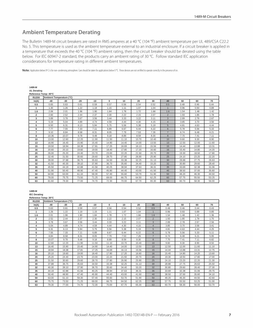
Ambient Temperature Derating
Note: Application below 0º C is for non-condensing atmosphere. Care should be taken for applications below 0 °C. These devices are not certified to operate correctly in the presence of ice.
The Bulletin 1489-M circuit breakers are rated in RMS amperes at a 40 °C (104 °F) ambient temperature per UL 489/CSA C22.2No. 5. This temperature is used as the ambient temperature external to an industrial enclosure. If a circuit breaker is applied ina temperature that exceeds the 40 °C (104 °F) ambient rating, then the circuit breaker should be derated using the tablebelow. For IEC 60947-2 standard, the products carry an ambient rating of 30 °C. Follow standard IEC applicationconsiderations for temperature rating in different ambient temperatures.
1489-MUL DeratingReference Temp: 40°C
RU200In(A) -40 -30 -20 -10 0 10 20 30 40 50 60 700.5 0.65 0.63 0.61 0.59 0.57 0.56 0.54 0.52 0.5 0.48 0.46 0.441 1.30 1.26 1.22 1.19 1.15 1.11 1.07 1.04 1 0.96 0.93 0.89
1.6 2.06 2.01 1.96 1.90 1.84 1.78 1.72 1.66 1.6 1.54 1.48 1.422 2.60 2.52 2.44 2.37 2.30 2.22 2.15 2.07 2 1.93 1.85 1.783 3.89 3.78 3.67 3.56 3.44 3.33 3.22 3.11 3 2.89 2.78 2.674 5.19 5.04 4.89 4.74 4.59 4.44 4.30 4.15 4 3.85 3.70 3.565 6.50 6.31 6.13 5.94 5.75 5.56 5.38 5.19 5 4.81 4.63 4.446 7.77 7.55 7.33 7.11 6.89 6.67 6.44 6.22 6 5.78 5.56 5.337 9.10 8.84 8.58 8.31 8.05 7.79 7.53 7.26 7 6.74 6.48 6.218 10.36 10.07 9.78 9.48 9.18 8.89 8.59 8.30 8 7.70 7.41 7.1110 13.00 12.60 12.20 11.90 11.50 11.10 10.70 10.40 10 9.60 9.30 8.9013 16.90 16.40 15.90 15.40 14.90 14.40 14.00 13.50 13 12.50 12.00 11.6015 19.50 18.94 18.38 17.81 17.25 16.69 16.13 15.56 15 14.44 13.88 13.3116 20.60 20.10 19.60 19.00 18.40 17.80 17.20 16.60 16 15.40 14.80 14.2020 26.00 25.20 24.40 23.70 23.00 22.20 21.50 20.70 20 19.30 18.50 17.8025 32.40 31.50 30.60 29.60 28.70 27.80 26.90 25.90 25 24.10 23.20 22.2030 39.00 37.88 36.75 35.63 34.50 33.38 32.25 31.13 30 28.88 27.75 26.6332 41.50 40.30 39.10 37.90 36.70 35.60 34.40 33.20 32 30.80 29.60 28.4035 45.50 44.19 42.88 41.56 40.25 38.94 37.63 36.31 35 33.69 32.38 31.0640 51.90 50.40 48.90 47.40 45.90 44.40 43.00 41.50 40 38.50 37.00 35.6050 64.90 63.00 61.10 59.30 57.40 55.60 53.70 51.90 50 48.20 46.30 44.5060 78.00 75.75 73.50 71.25 69.00 66.75 64.50 62.25 60 57.75 55.50 53.2563 81.60 79.30 77.00 74.70 72.30 70.00 67.70 65.30 63 60.70 58.30 56.00
1489-MIEC DeratingReference Temp: 30°C
RU200In(A) -40 -30 -20 -10 0 10 20 30 40 50 60 700.5 0.63 0.61 0.59 0.57 0.56 0.54 0.52 0.5 0.48 0.46 0.44 0.431 1.26 1.22 1.19 1.15 1.11 1.07 1.04 1 0.96 0.93 0.89 0.85
1.6 2.01 1.96 1.90 1.84 1.78 1.72 1.66 1.6 1.54 1.48 1.42 1.362 2.52 2.44 2.37 2.30 2.22 2.15 2.07 2 1.93 1.85 1.78 1.703 3.78 3.67 3.56 3.44 3.33 3.22 3.11 3 2.89 2.78 2.67 2.564 5.04 4.89 4.74 4.59 4.44 4.30 4.15 4 3.85 3.70 3.56 3.415 6.31 6.13 5.94 5.75 5.56 5.38 5.19 5 4.81 4.63 4.44 4.256 7.55 7.33 7.11 6.89 6.67 6.44 6.22 6 5.78 5.56 5.33 5.117 8.84 8.58 8.31 8.05 7.79 7.53 7.26 7 6.74 6.48 6.21 5.958 10.07 9.78 9.48 9.18 8.89 8.59 8.30 8 7.70 7.41 7.11 6.8210 12.60 12.20 11.90 11.50 11.10 10.70 10.40 10 9.60 9.30 8.90 8.5013 16.40 15.90 15.40 14.90 14.40 14.00 13.50 13 12.50 12.00 11.60 11.1015 18.94 18.38 17.81 17.25 16.69 16.13 15.56 15 14.44 13.88 13.31 12.7516 20.10 19.60 19.00 18.40 17.80 17.20 16.60 16 15.40 14.80 14.20 13.6020 25.20 24.40 23.70 23.00 22.20 21.50 20.70 20 19.30 18.50 17.80 17.0025 31.50 30.60 29.60 28.70 27.80 26.90 25.90 25 24.10 23.20 22.20 21.3030 37.88 36.75 35.63 34.50 33.38 32.25 31.13 30 28.88 27.75 26.63 25.5032 40.30 39.10 37.90 36.70 35.60 34.40 33.20 32 30.80 29.60 28.40 27.3035 44.19 42.88 41.56 40.25 38.94 37.63 36.31 35 33.69 32.38 31.06 29.7540 50.40 48.90 47.40 45.90 44.40 43.00 41.50 40 38.50 37.00 35.60 34.1050 63.00 61.10 59.30 57.40 55.60 53.70 51.90 50 48.20 46.30 44.50 42.6060 75.75 73.50 71.25 69.00 66.75 64.50 62.25 60 57.75 55.50 53.25 51.0063 79.30 77.00 74.70 72.30 70.00 67.70 65.30 63 60.70 58.30 56.00 53.70
Ambient Temperature (°C)
Ambient Temperature (°C)

1489-M Circuit Breakers
Rockwell Automation Publication 1492-TD014B-EN-P — February 20168
Tripping CharacteristicsC Curve
= Tripping Curvefrom cold state
Trip
pin
g t
ime
(s)
Multiple of rated current I/In
AC
D Curve
= Tripping Curvefrom cold state
Trip
pin
g t
ime
(s)
Multiple of rated current I/In
AC

1489-M Circuit Breakers
Rockwell Automation Publication 1492-TD014B-EN-P — February 2016 9
Accessory Approximate DimensionsNote: Dimensions are shown in millimeters (inches). Dimensions are not intended for manufacturing purposes.
8.8 mm (0.35”)
74 mm(2.91”)
99 mm (3.90”)
1489-AMRS3
17.5 mm (0.69”)
74 mm(2.91”)
99 mm (3.90”)
64.2 mm (2.53”)
1489-AMST1 and 1489-AMST2
8.8 mm (0.35”)
74 mm(2.91”)
99 mm (3.90”)
1489-AMRA3
1489-M Circuit Breakers
Rockwell Automation Publication 1492-TD014B-EN-P — February 201610
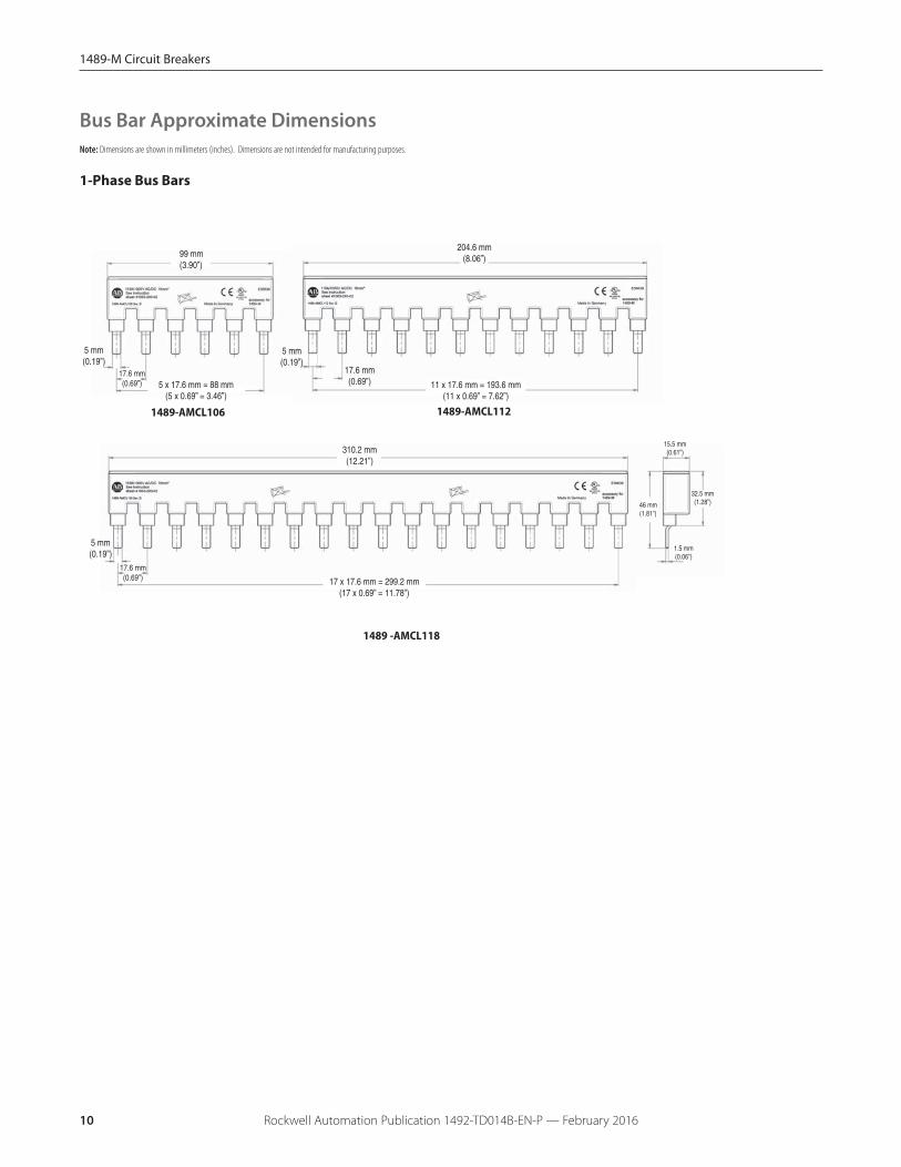
Bus Bar Approximate DimensionsNote: Dimensions are shown in millimeters (inches). Dimensions are not intended for manufacturing purposes.
1-Phase Bus Bars
1489 -AMCL118
32.5 mm(1.28”)
15.5 mm(0.61”)
46 mm(1.81”)
1.5 mm(0.06”)
310.2 mm(12.21”)
17 x 17.6 mm = 299.2 mm(17 x 0.69” = 11.78”)
5
99 mm(3.90”)
17.6 mm(0.69”) 5 x 17.6 mm = 88 mm
(5 x 0.69” = 3.46”)
5 mm(0.19”)
204.6 mm(8.06”)
11 x 17.6 mm = 193.6 mm(11 x 0.69” = 7.62”)
17.6 mm(0.69”)
5 mm(0.19”)
17.6 mm(0.69”)
5 mm(0.19”)
1489-AMCL1121489-AMCL106
1489-M Circuit Breakers
Rockwell Automation Publication 1492-TD014B-EN-P — February 2016 11
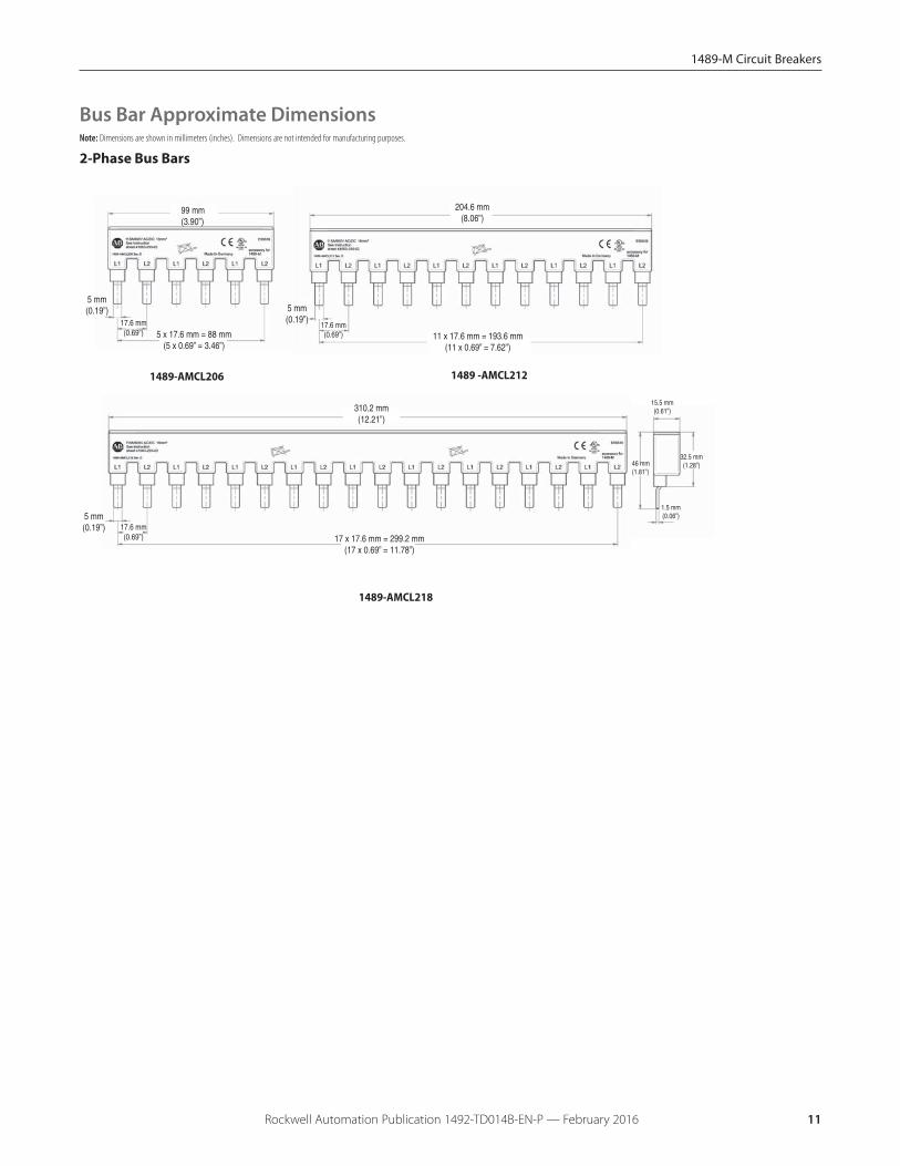
2-Phase Bus Bars
17.6
5
32.5 mm(1.28”)
15.5 mm(0.61”)
46 mm(1.81”)
1.5 mm(0.06”)
17 x 17.6 mm = 299.2 mm(17 x 0.69” = 11.78”)
99 mm(3.90”)
17.6 mm(0.69”) 5 x 17.6 mm = 88 mm
(5 x 0.69” = 3.46”)
5 mm(0.19”)
204.6 mm(8.06”)
17.6 mm(0.69”)
5 mm(0.19”)
5 mm(0.19”)
310.2 mm(12.21”)
11 x 17.6 mm = 193.6 mm(11 x 0.69” = 7.62”)
17.6 mm(0.69”)
1489-AMCL218
Bus Bar Approximate DimensionsNote: Dimensions are shown in millimeters (inches). Dimensions are not intended for manufacturing purposes.
1489-AMCL206 1489 -AMCL212

1489-M Circuit Breakers
Rockwell Automation Publication 1492-TD014B-EN-P — February 201612
3-Phase Bus Bars
55
32.5 mm(1.28”)
15.5 mm(0.61”)
46 mm(1.81”)
1.5 mm(0.06”)
17 x 17.6 mm = 299.2 mm(17 x 0.69” = 11.78”)
99 mm(3.90”)
17.6 mm(0.69”)
5 x 17.6 mm = 88 mm(5 x 0.69” = 3.46”)
5 mm(0.19”)
204.6 mm(8.06”)
17.6 mm(0.69”)
5 mm(0.19”)
5 mm(0.19”)
310.2 mm(12.21”)
11 x 17.6 mm = 193.6 mm(11 x 0.69” = 7.62”)
17.6 mm(0.69”)
1489-AMCL318
1489-AMCL306 1489 -AMCL312
Bus Bar Approximate DimensionsNote: Dimensions are shown in millimeters (inches). Dimensions are not intended for manufacturing purposes.
1489-M Circuit Breakers
Rockwell Automation Publication 1492-TD014B-EN-P — February 2016 13
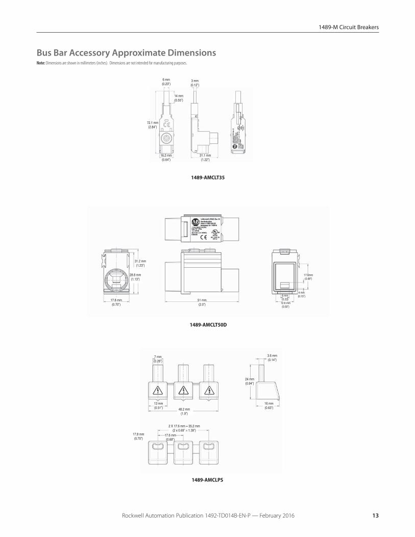
14 mm(0.55”)
6 mm(0.23”)
72.1 mm(2.84”)
16.2 mm(0.64”)
3 mm(0.12”)
31.1 mm(1.22”)
1489-AMCLT35
17.8 mm(0.70”)
28.8 mm(1.13”)
51 mm(2.0”)
17.6mm(0.69”)
4 mm(0.15”)
12.6 mm(0.50”)
6 mm(0.23)
31.2 mm(1.23”)
1489-AMCLT50D
13 mm(0.51”)
7 mm(0.28”)
48.2 mm(1.9”)
17.8 mm(0.70”)
2 X 17.6 mm = 35.2 mm(2 x 0.69” = 1.39”)
16 mm(0.63”)
24 mm(0.94”)
3.6 mm(0.14”)
17.6 mm(0.69”)
1489-AMCLPS
Bus Bar Accessory Approximate DimensionsNote: Dimensions are shown in millimeters (inches). Dimensions are not intended for manufacturing purposes.

1489-M Circuit Breakers
Rockwell Automation Publication 1492-TD014B-EN-P — February 201614
Notes
1492-SP Supplementary Protectors
Rockwell Automation Publication 1492-TD014B-EN-P — February 2016 15
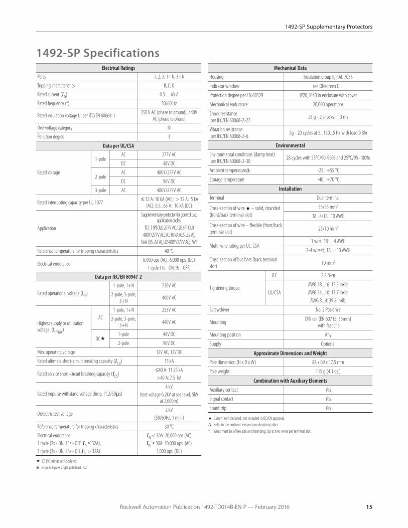
1492-SP SpecificationsMechanical Data
Housing Insulation group II, RAL 7035
Indicator window red ON/green OFF
Protection degree per EN 60529 IP20, IP40 in enclosure with cover
Mechanical endurance 20,000 operations
Shock resistanceper IEC/EN 60068-2-27 25 g - 2 shocks - 13 ms
Vibration resistanceper IEC/EN 60068-2-6 5g - 20 cycles at 5...150...5 Hz with load 0.8In
EnvironmentalEnvironmental conditions (damp heat)per IEC/EN 60068-2-30 28 cycles with 55°C/90-96% and 25°C/95-100%
Ambient temperatureΔ -25...+55 °C
Storage temperature -40...+70 °C
InstallationTerminal Dual terminal
Cross-section of wire ♦ – solid, stranded(front/back terminal slot)
35/35 mm2
18...4/18...10 AWG
Cross-section of wire – flexible (front/backterminal slot) 25/10 mm2
Multi-wire rating per UL, CSA1 wire, 18…4 AWG
2-4 wires‡, 18…10 AWG
Cross-section of bus bars (back terminalslot) 10 mm2
Tightening torque
IEC 2.8 N•m
UL/CSAAWG 18...16: 13.3 in•lb. AWG 14...10: 17.7 in•lb.
AWG 8...4: 39.8 in•lb.
Screwdriver No. 2 Pozidrive
Mounting DIN rail (EN 60715, 35mm)with fast clip
Mounting position Any
Supply Optional
Approximate Dimensions and WeightPole dimension (H x D x W) 88 x 69 x 17.5 mm
Pole weight 115 g (4.1 oz.)
Combination with Auxiliary ElementsAuxiliary contact Yes
Signal contact Yes
Shunt trip Yes
♦ 35mm2 self-declared, not included in IEC/EN approval.
Δ Refer to the ambient temperature derating tables.
‡ Wires must be of like size and stranding. Up to two wires per terminal slot.
Electrical RatingsPoles 1, 2, 3, 1+N, 3+N
Tripping characteristics B, C, D
Rated current (In) 0.5…63 A
Rated frequency (f ) 50/60 Hz
Rated insulation voltage Ui per IEC/EN 60664-1 250 V AC (phase to ground), 440VAC (phase to phase)
Overvoltage category III
Pollution degree 3
Data per UL/CSA
Rated voltage
1-poleAC 277V AC
DC 48V DC
2-poleAC 480Y/277V AC
DC 96V DC
3-pole AC 480Y/277V AC
Rated interrupting capacity per UL 1077 ≤ 32 A: 10 kA (AC); > 32 A: 5 kA(AC); 0.5...63 A: 10 kA (DC)
Application
Supplementary protector for general use;application codes:
TC1: [1P] OL0 277V AC, [2P, 3P] OL0 480Y/277V AC; SC: 10 kA (0.5...32 A),
5 kA (35...63 A), U2 480Y/277V AC; FW3
Reference temperature for tripping characteristics 40 °C
Electrical endurance6,000 ops (AC), 6,000 ops. (DC)
1 cycle (1s - ON, 9s - OFF)
Data per IEC/EN 60947-2
Rated operational voltage (Ue) 1-pole, 1+N 230V AC
2-pole, 3-pole,3+N 400V AC
Highest supply or utilizationvoltage (Umax)
AC1-pole, 1+N 253V AC
2-pole, 3-pole,3+N 440V AC
DC�1-pole 48V DC
2-pole 96V DC
Min. operating voltage 12V AC, 12V DC
Rated ultimate short-circuit breaking capacity (Icu) 15 kA
Rated service short-circuit breaking capacity (Ics)≤40 A: 11.25 kA >40 A: 7.5 kA
Rated impulse withstand voltage Uimp. (1.2/50μs) 4 kV
(test voltage 6.2kV at sea level, 5kVat 2,000m)
Dielectric test voltage2 kV
(50/60Hz, 1 min.)
Reference temperature for tripping characteristics 30 °C
Electrical endurance1 cycle (2s - ON, 13s - OFF, In ≤ 32A), 1 cycle (2s - ON, 28s - OFF,In > 32A)
In < 30A: 20,000 ops (AC)In ≥ 30A: 10,000 ops. (AC)
1,000 ops. (DC)
� IEC DC ratings self-declared.
♣ 2-pole/3-pole single pole load: TC2.

1492-SP Supplementary Protectors
Rockwell Automation Publication 1492-TD014B-EN-P — February 201616
Note: Dimensions are shown in millimeters (inches). Dimensions are not intended for manufacturing purposes.
Approximate Dimensions
Power Loss Due to Current
Rated Current [A]Power Loss Per
Pole [W] Rated Current [A]Power Loss Per
Pole [W]0.5 1.4 13 2.3
1 1.4 15 2.4
2 1.8 16 2.5
3 1.6 20 2.5
4 1.8 25 3.2
5 1.9 30 3.5
6 2.0 32 3.7
7 1.1 40 4.5
8 1.5 50 4.5
10 2.1 63 5.4
88 mm (3.46”)
17.5 mm (0.69”)
70 mm(2.8” )35 mm
(1.4” )53 mm (2.0”)
88 mm (3.46”)
69 mm (2.7”)
75 mm (3.0”)
67 mm (2.6”)
74 mm (2.9”)
1-Pole
1 Pole + N, 2-, 3-, 3 Pole + N 1 Pole + N, 2-Pole 3-Pole
1-Pole
3-Pole + N
Zero-stack Derating
The installation of several miniature circuit breaker side by side with rated current on all polesrequires a correction factor to the rated current (not required if spacers are used).
No. of Adjacent Devices Factor1 1
2,3 0.9
4,5 0.8
≥ 6 0.75
1492-SP Supplementary Protectors
Rockwell Automation Publication 1492-TD014B-EN-P — February 2016 17
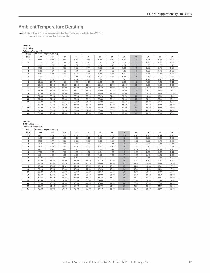
Ambient Temperature DeratingNote: Application below 0º C is for non-condensing atmosphere. Care should be taken for applications below 0 °C. These
devices are not certified to operate correctly in the presence of ice.
1492-SPUL DeratingReference Temp: 40°C
RP200In(A) -40 -30 -20 -10 0 10 20 30 40 50 60 700.5 0.65 0.63 0.61 0.59 0.57 0.56 0.54 0.52 0.5 0.48 0.46 0.441 1.30 1.26 1.22 1.19 1.15 1.11 1.07 1.04 1 0.96 0.93 0.892 2.60 2.52 2.44 2.37 2.30 2.22 2.15 2.07 2 1.93 1.85 1.783 3.89 3.78 3.67 3.56 3.44 3.33 3.22 3.11 3 2.89 2.78 2.674 5.19 5.04 4.89 4.74 4.59 4.44 4.30 4.15 4 3.85 3.70 3.565 6.50 6.31 6.13 5.94 5.75 5.56 5.38 5.19 5 4.81 4.63 4.446 7.77 7.55 7.33 7.11 6.89 6.67 6.44 6.22 6 5.78 5.56 5.337 9.10 8.84 8.58 8.31 8.05 7.79 7.53 7.26 7 6.74 6.48 6.218 10.36 10.07 9.78 9.48 9.18 8.89 8.59 8.30 8 7.70 7.41 7.11
10 13.00 12.60 12.20 11.90 11.50 11.10 10.70 10.40 10 9.60 9.30 8.9013 16.90 16.40 15.90 15.40 14.90 14.40 14.00 13.50 13 12.50 12.00 11.6015 19.50 18.94 18.38 17.81 17.25 16.69 16.13 15.56 15 14.44 13.88 13.3116 20.60 20.10 19.60 19.00 18.40 17.80 17.20 16.60 16 15.40 14.80 14.2020 26.00 25.20 24.40 23.70 23.00 22.20 21.50 20.70 20 19.30 18.50 17.8025 32.40 31.50 30.60 29.60 28.70 27.80 26.90 25.90 25 24.10 23.20 22.2030 39.00 37.88 36.75 35.63 34.50 33.38 32.25 31.13 30 28.88 27.75 26.6332 41.50 40.30 39.10 37.90 36.70 35.60 34.40 33.20 32 30.80 29.60 28.4040 51.90 50.40 48.90 47.40 45.90 44.40 43.00 41.50 40 38.50 37.00 35.6050 64.90 63.00 61.10 59.30 57.40 55.60 53.70 51.90 50 48.20 46.30 44.5063 81.60 79.30 77.00 74.70 72.30 70.00 67.70 65.30 63 60.70 58.30 56.00
1492-SPIEC DeratingReference Temp: 30°C
RP200In(A) -40 -30 -20 -10 0 10 20 30 40 50 60 700.5 0.63 0.61 0.59 0.57 0.56 0.54 0.52 0.5 0.48 0.46 0.44 0.431 1.26 1.22 1.19 1.15 1.11 1.07 1.04 1 0.96 0.93 0.89 0.852 2.52 2.44 2.37 2.30 2.22 2.15 2.07 2 1.93 1.85 1.78 1.703 3.78 3.67 3.56 3.44 3.33 3.22 3.11 3 2.89 2.78 2.67 2.564 5.04 4.89 4.74 4.59 4.44 4.30 4.15 4 3.85 3.70 3.56 3.415 6.31 6.13 5.94 5.75 5.56 5.38 5.19 5 4.81 4.63 4.44 4.256 7.55 7.33 7.11 6.89 6.67 6.44 6.22 6 5.78 5.56 5.33 5.117 8.84 8.58 8.31 8.05 7.79 7.53 7.26 7 6.74 6.48 6.21 5.958 10.07 9.78 9.48 9.18 8.89 8.59 8.30 8 7.70 7.41 7.11 6.82
10 12.60 12.20 11.90 11.50 11.10 10.70 10.40 10 9.60 9.30 8.90 8.5013 16.40 15.90 15.40 14.90 14.40 14.00 13.50 13 12.50 12.00 11.60 11.1015 18.94 18.38 17.81 17.25 16.69 16.13 15.56 15 14.44 13.88 13.31 12.7516 20.10 19.60 19.00 18.40 17.80 17.20 16.60 16 15.40 14.80 14.20 13.6020 25.20 24.40 23.70 23.00 22.20 21.50 20.70 20 19.30 18.50 17.80 17.0025 31.50 30.60 29.60 28.70 27.80 26.90 25.90 25 24.10 23.20 22.20 21.3030 37.88 36.75 35.63 34.50 33.38 32.25 31.13 30 28.88 27.75 26.63 25.5032 40.30 39.10 37.90 36.70 35.60 34.40 33.20 32 30.80 29.60 28.40 27.3040 50.40 48.90 47.40 45.90 44.40 43.00 41.50 40 38.50 37.00 35.60 34.1050 63.00 61.10 59.30 57.40 55.60 53.70 51.90 50 48.20 46.30 44.50 42.6063 79.30 77.00 74.70 72.30 70.00 67.70 65.30 63 60.70 58.30 56.00 53.70
Ambient Temperature (°C)
Ambient Temperature (°C)

1492-SP Supplementary Protectors
Rockwell Automation Publication 1492-TD014B-EN-P — February 201618
Tripping CharacteristicsB Curve
= Tripping Curvefrom cold state
Trip
pin
g t
ime
(s)
Multiple of rated current I/In
AC
B and C Curve - 230/400V AC Let-through Energy
Let-
thro
ugh
ener
gy i2 t /
A2 s
Let-
thro
ugh
ener
gy i2 t /
A2 s
1492-SP Supplementary Protectors
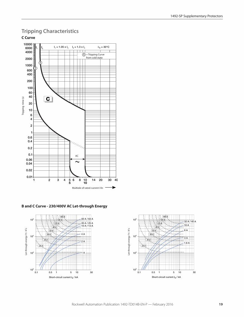
Rockwell Automation Publication 1492-TD014B-EN-P — February 2016 19
B and C Curve - 230/400V AC Let-through Energy
Let-
thro
ugh
ener
gy i2 t /
A2 s
Let-
thro
ugh
ener
gy i2 t /
A2 s
C Curve
= Tripping Curvefrom cold state
Trip
pin
g t
ime
(s)
Multiple of rated current I/In
AC
Tripping Characteristics

1492-SP Supplementary Protectors
Rockwell Automation Publication 1492-TD014B-EN-P — February 201620
D Curve
= Tripping Curvefrom cold state
Trip
pin
g t
ime
(s)
Multiple of rated current I/In
AC
D Curve - 230/400V AC Let-through Energy
Let-
thro
ugh
ener
gy i2 t /
A2 s
Short-circuit current Ik / kA
Let-
thro
ugh
ener
gy i2 t /
A2 s
Short-circuit current Ik / kA
Tripping Characteristics

1492-SP Supplementary Protectors
Rockwell Automation Publication 1492-TD014B-EN-P — February 2016 21
Note: Dimensions are shown in millimeters (inches). Dimensions are not intended for manufacturing purposes.
85 mm(3.35”)
8.8 mm(0.35”)
74 mm(2.91”)
189-ASCR3
85 mm(3.35”)
8.8 mm(0.35”)
74 mm(2.91”)
189-AR3
Accessory Approximate Dimensions
189-AST1 and 189-AST2
17.5 mm(.69”)
88 mm(3.46”)
73.3 mm(2.86”)
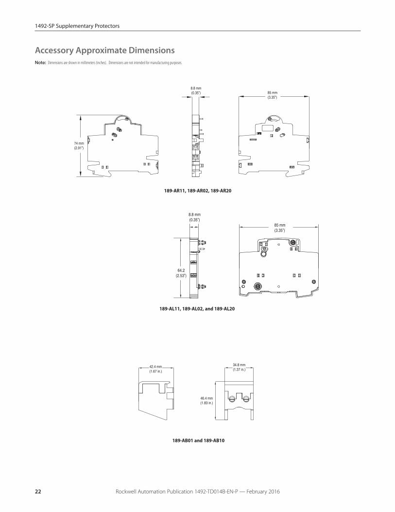
1492-SP Supplementary Protectors
Rockwell Automation Publication 1492-TD014B-EN-P — February 201622
189-AR11, 189-AR02, 189-AR20
85 mm(3.35”)
8.8 mm(0.35”)
74 mm(2.91”)
189-AL11, 189-AL02, and 189-AL20
46.4 mm(1.83 in.)
34.8 mm(1.37 in.)
42.4 mm(1.67 in.)
189-AB01 and 189-AB10
Note: Dimensions are shown in millimeters (inches). Dimensions are not intended for manufacturing purposes.
Accessory Approximate Dimensions
8.8 mm(0.35”)
64.2(2.53”)
85 mm(3.35”)

1492-SP Supplementary Protectors
Rockwell Automation Publication 1492-TD014B-EN-P — February 2016 23
Bus Bar Approximate Dimensions
1-Phase Bus Bars
1492-A1B1
1-Phase Bus Bars, with Auxiliary Contact
1492-A1B1H
1012 mm (39.84”)
56 x 17.8 = 996.8 mm (56 x 0.70 = 39.24”)
5.5 mm(0.22”)
17.8 mm (0.70”)
15 mm(0.59”)
15.6 mm(0.61”)
2.5 mm(0.10”)
5 mm(0.20”)
1009 mm +2
(39.72” +2)
5.5 mm(0.22”)
17.8 mm(0.70”)
56 x 17.8 = 996.8 mm(56 x 0.70 = 39.24”)
5 mm(0.20”)
2.5 mm(0.10”)
15 mm(0.59”)
15 mm
5.5 mm(0.22”)
27 mm (1.06”)
15 mm(0.59”)
2.5 mm(0.10”)
16 mm(0.63”)
985 mm +2 (38.78” +2)
5 mm(0.20”)
36 x 27 = 972 mm (36 x 1.06 = 38.27”)
5.5 mm(0.22”)
27 mm (1.06”)
15 mm(0.59”)
2.5 mm(0.10”)
15 mm(0.59”)
985 mm +2 (38.78” +2)
5 mm(0.20”)
36 x 27 = 972 mm (36 x 1.06 = 38.27”)
Note: Dimensions are shown in millimeters (inches). Dimensions are not intended for manufacturing purposes.
1492-A1B8
1492-A1B8H
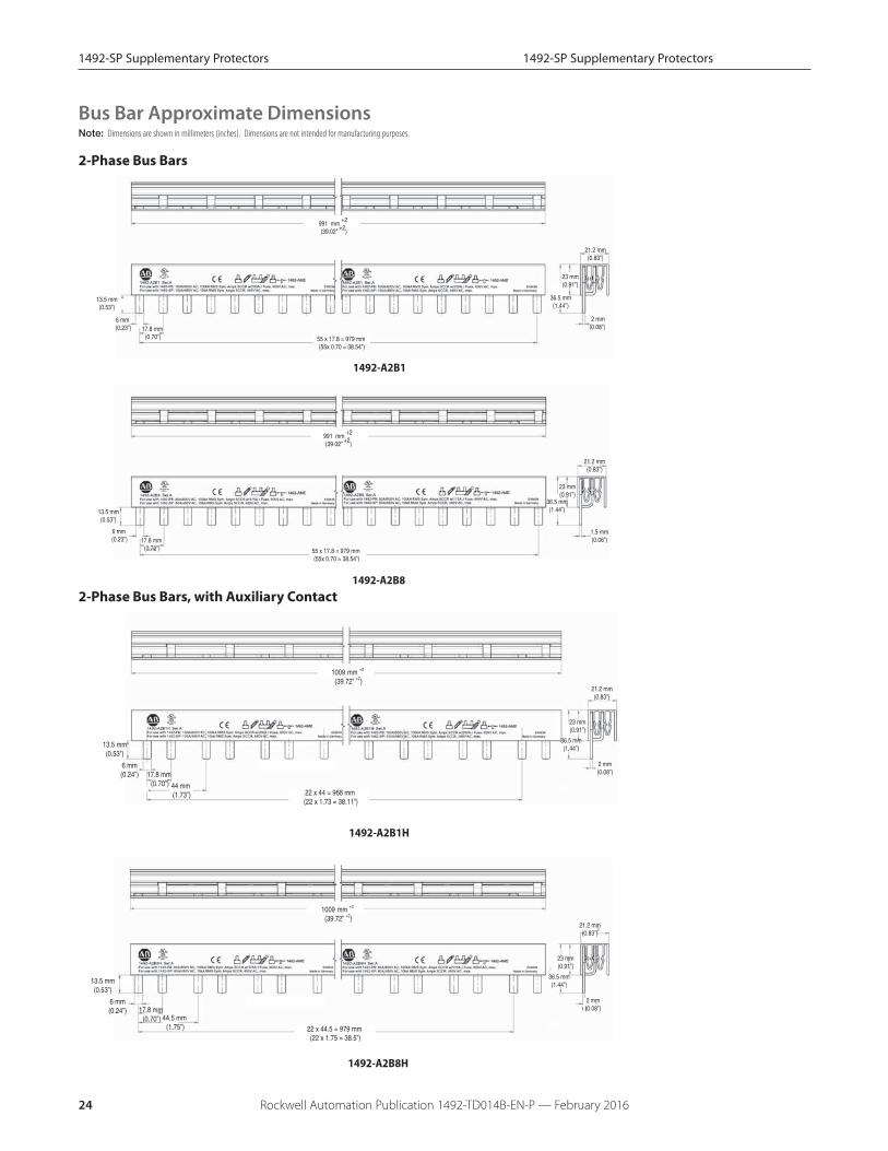
1492-SP Supplementary Protectors
2-Phase Bus Bars
1492-A2B1
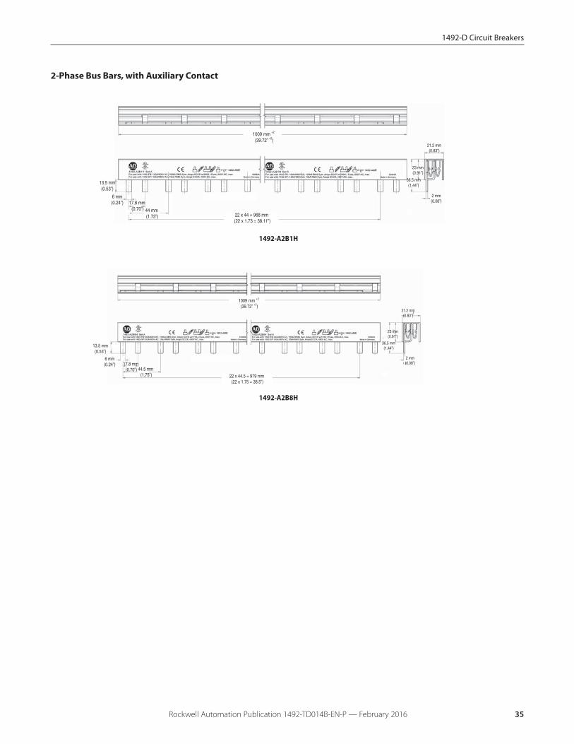
2-Phase Bus Bars, with Auxiliary Contact
1492-A2B8H
13.5 mm(0.53”)
6 mm (0.23”)
21.2 mm(0.83”)
991 mm +2 (39.02” +2)
17.8 mm (0.70”) 55 x 17.8 = 979 mm
(55x 0.70 = 38.54”)
36.5 mm(1.44”)
23 mm(0.91”)
2 mm(0.08”)
13.5 mm(0.53”)
6 mm (0.23”)
21.2 mm(0.83”)
991 mm +2 (39.02” +2)
17.8 mm (0.70”) 55 x 17.8 = 979 mm
(55x 0.70 = 38.54”)
36.5 mm(1.44”)
23 mm(0.91”)
1.5 mm(0.06”)
1492-A2B8
17.8 mm (0.70”)
1009 mm +2 (39.72” +2)
22 x 44 = 968 mm (22 x 1.73 = 38.11”)
44 mm (1.73”)
21.2 mm(0.83”)
36.5 mm(1.44”)
23 mm(0.91”)
2 mm(0.08”)
13.5 mm(0.53”)
6 mm(0.24”)
17.8 mm (0.70”)
1009 mm +2 (39.72” +2)
22 x 44.5 = 979 mm (22 x 1.75 = 38.5”)
44.5 mm (1.75”)
21.2 mm(0.83”)
36.5 mm(1.44”)
23 mm(0.91”)
2 mm(0.08”)
13.5 mm(0.53”)
6 mm(0.24”)
1492-A2B1H
Bus Bar Approximate DimensionsNote: Dimensions are shown in millimeters (inches). Dimensions are not intended for manufacturing purposes.
24 Rockwell Automation Publication 1492-TD014B-EN-P — February 2016
1492-SP Supplementary Protectors
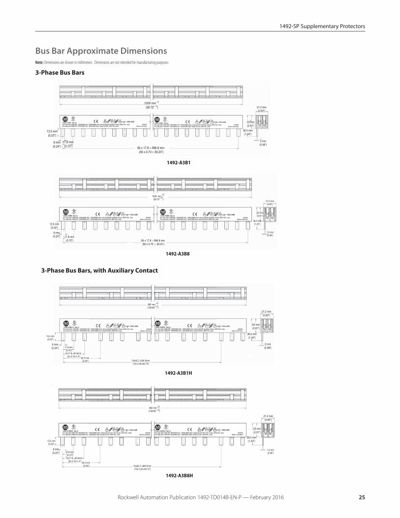
3-Phase Bus Bars
1492-A3B1H
1492-A3B8H
56 x 17.8 = 996.8 mm (56 x 0.70 = 39.24”)
21.2 mm(0.83”)
36.5 mm(1.44”)
23 mm(0.91”)
2 mm(0.08”)
6 mm(0.24”)
13.5 mm(0.53”)
17.8 mm (0.70”)
1009 mm +2 (39.72” +2)
17.8 mm (0.70”)
13.5 mm(0.53”)
6 mm(0.24”)
1009 mm +2
(39.72”
+2)
56 x 17.8 = 996.8 mm (56 x 0.70” = 39.24”)
21.2 mm(0.83”)
36.5 mm(1.44”)
23 mm(0.91”)
1.5 mm(0.06”)
21.2 mm(0.83”)
36.5 mm(1.44”)
23 mm(0.91”)
2 mm(0.08”)
6 mm(0.24”)
13.5 mm(0.53”)
17.8 mm (0.70”)
62.3 mm (2.45”)
2x17.8 =35.6mm (2x 0.70=1.4”)
15x62.3 =934.5mm (15x 2.45=36.79”)
982 mm +2
(138.66” +2)
21.2 mm(0.83”)
36.5 mm(1.44”)
23 mm(0.91”)
6 mm(0.24”)
13.5 mm(0.53”)
17.8 mm (0.70”)
62.3 mm (2.45”)
2x17.8 =35.6mm (2x 0.70=1.4”)
982 mm +2
(138.66” +2)
15x62.3 =994.5mm (15x 2.45=39.15”)
1.5 mm(0.06”)
1492-A3B1
3-Phase Bus Bars, with Auxiliary Contact
1492-A3B8
Bus Bar Approximate DimensionsNote: Dimensions are shown in millimeters. Dimensions are not intended for manufacturing purposes.
25Rockwell Automation Publication 1492-TD014B-EN-P — February 2016
1492-SP Supplementary Protectors
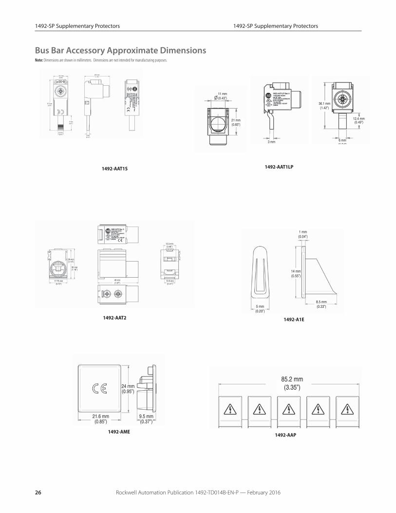
1492-SP Supplementary Protectors
36.1 mm(1.42”)
12.4 mm(0.49”)
6 mm(0 24”)
28.5 mm(1.12”)
57.5 mm(2.26”)
17 mm(0.67”)
6.3 mm(0.25”)
16.2 mm(0.64”)
3 mm(0.12”)
17.75 mm(0.70”)
29 mm(1.14”)
40 mm(1.57”)
10.5 mm(0.41”)
30 mm(1.18”)
12.3 mm(0.48”)
1492-AAT1LP 1492-AAT1S
1492-AAT2
11 mm(0.43”)
21 mm(0.83”)
3 mm
Bus Bar Accessory Approximate DimensionsNote: Dimensions are shown in millimeters. Dimensions are not intended for manufacturing purposes.
5 mm(0.20”)
14 mm(0.55”)
8.5 mm(0.33”)
1 mm(0.04”)
1492-A1E
21.6 mm(0.85”)
9.5 mm(0.37”)
24 mm(0.95”)
1492-AME
85.2 mm(3.35”)
1492-AAP
26 Rockwell Automation Publication 1492-TD014B-EN-P — February 2016
1492-SP Supplementary Protectors

1492-D Circuit Breakers
Rockwell Automation Publication 1492-TD014B-EN-P — February 2016 27
1492-D SpecificationsElectrical Ratings
Poles 1, 2
Tripping characteristics C
Rated current (In) 0.5…63 A
Rated frequency (f) 0 Hz (DC only)
Rated insulation voltage Ui per IEC/EN 60664-1 250 V AC (phase to ground), 440V AC (phaseto phase)
Overvoltage category III
Pollution degree 3
Data per UL/CSA
Rated voltage1-pole 250V DC
2-pole 500V DC
Rated interrupting capacity per UL 1077 10 kA
Application
Supplementary Protector for DC applicationuse; application codes:
TC0; OL0 250V DC, SC: 10kA; U1250V DC; FW0
Reference temperature for trippingcharacteristics 25 °C
Electrical endurance 6,000 ops
Data per IEC/EN 60947-2
Rated operational voltage (Ue) 1-pole 220V DC
2-pole 440V DC
Highest supply or utilizationvoltage (Umax)
1-pole 250V DC
2-pole 500V DC
Min. operating voltage 12V DC
Rated ultimate short-circuit breaking capacity(Icu) 10 kA
Rated service short-circuit breaking capacity(Ics) 10 kA
Rated impulse withstand voltage Uimp.(1.2/50μs)
4 kV (test voltage 6.2kV at sea level, 5kV at
2,000m)
Dielectric test voltage2 kV
(50/60Hz, 1 min.)
Reference temperature for trippingcharacteristics 55 °C
Electrical endurance1 cycle (2s - ON, 13s - OFF, In ≤ 32A), 1 cycle (2s - ON, 28s - OFF,In > 32A)
1,500 ops.
Mechanical DataHousing Insulation group II, RAL 7035
Indicator window red ON/green OFF
Protection degree per EN 60529 IP20, IP40 in enclosure with cover
Mechanical endurance 20,000 operations
Shock resistanceper IEC/EN 60068-2-27 25 g - 2 shocks - 13 ms
Vibration resistanceper IEC/EN 60068-2-6 5g - 20 cycles at 5...150...5 Hz with load 0.8In
EnvironmentalEnvironmental conditions (damp heat)per IEC/EN 60068-2-30 28 cycles with 55°C/90-96% and 25°C/95-100%
Ambient temperatureΔ -25...+55 °C
Storage temperature -40...+70 °C
InstallationTerminal Dual terminal
Cross-section of wire ♦ – solid, stranded (front/back terminal slot)
35/35 mm2
18...4/18...10 AWG
Cross-section of wire – flexible (front/back terminal slot)
25/10 mm2
Multi-wire rating per UL, CSA1 wire, 18…4 AWG
2-4 wires‡, 18…10 AWG
Cross-section of bus bars (back terminal slot)
10 mm2
Tightening torque
IEC 2.8 N•m
UL/CSAAWG 18...16: 13.3 in•lb. AWG 14...10:17.7 in•lb. AWG 8...4: 39.8 in•lb.
Screwdriver No. 2 Pozidrive
Mounting DIN rail (EN 60715, 35mm)with fast clip
Mounting position Any
Supply Note polarity of device
Approximate Dimensions and WeightPole dimension (H x D x W) 88 x 69 x 17.5 mm
Pole weight 125 g (4.5 oz.)
Combination with Auxiliary ElementsAuxiliary contact Yes
Signal contact Yes
Shunt trip Yes
♦ 35mm2 self-declared, not included in IEC/EN approval.
Δ Refer to the ambient temperature derating tables.
‡ Wires must be of like size and stranding. Up to two wires per terminal slot.
1492-D Circuit Breakers
Rockwell Automation Publication 1492-TD014B-EN-P — February 201628
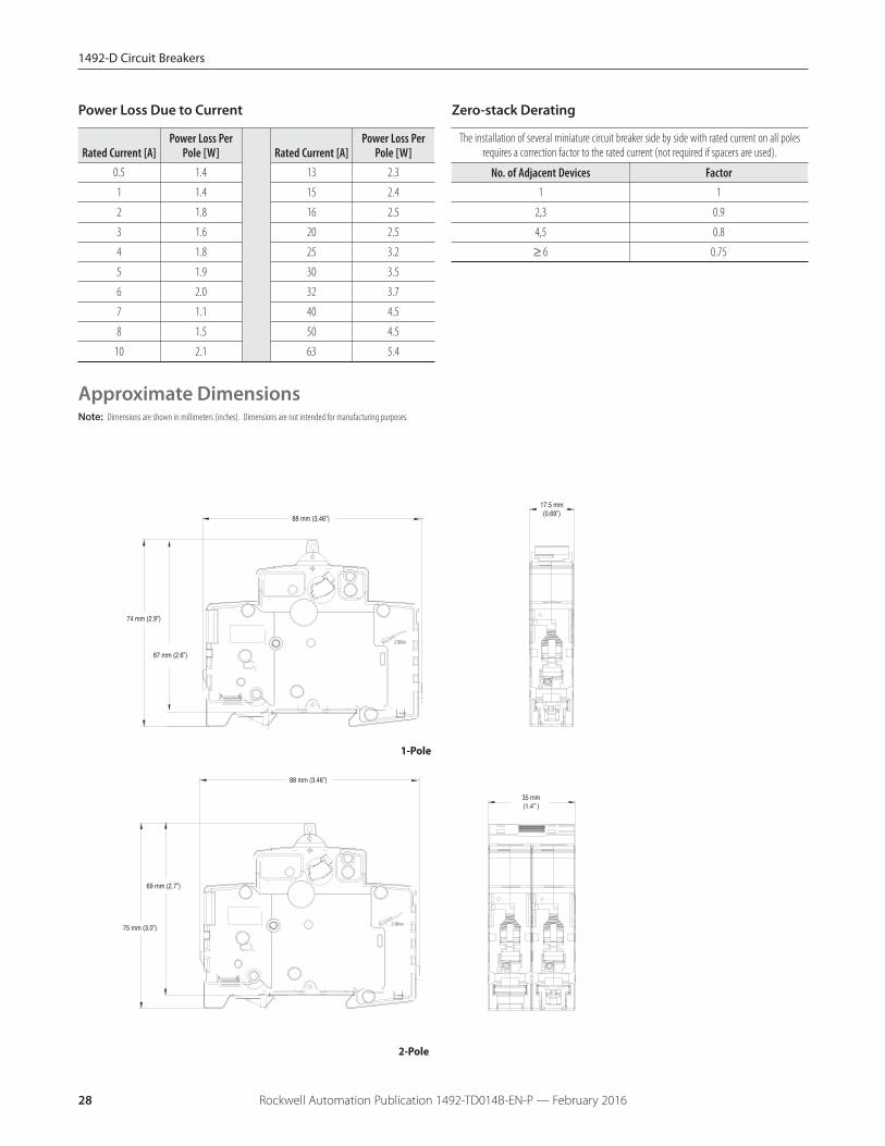
Power Loss Due to Current
Rated Current [A]Power Loss Per
Pole [W] Rated Current [A]Power Loss Per
Pole [W]0.5 1.4 13 2.3
1 1.4 15 2.4
2 1.8 16 2.5
3 1.6 20 2.5
4 1.8 25 3.2
5 1.9 30 3.5
6 2.0 32 3.7
7 1.1 40 4.5
8 1.5 50 4.5
10 2.1 63 5.4
Zero-stack Derating
The installation of several miniature circuit breaker side by side with rated current on all polesrequires a correction factor to the rated current (not required if spacers are used).
No. of Adjacent Devices Factor1 1
2,3 0.9
4,5 0.8
≥ 6 0.75
Approximate DimensionsNote: Dimensions are shown in millimeters (inches). Dimensions are not intended for manufacturing purposes.
88 mm (3.46”)
17.5 mm (0.69”)
35 mm (1.4” )
88 mm (3.46”)
69 mm (2.7”)
75 mm (3.0”)
67 mm (2.6”)
74 mm (2.9”)
2-Pole
1-Pole

1492-D Circuit Breakers
Rockwell Automation Publication 1492-TD014B-EN-P — February 2016 29
Ambient Temperature DeratingNote: Application below 0º C is for non-condensing atmosphere. Care should be taken for applications below 0 °C. These
devices are not certified to operate correctly in the presence of ice.
Reference temperature = 30 °CTemperature Derating, IEC
Bulletin 1492-D
-25 -20 -10 0 10 20 30 40 50 550.5 0.6 0.6 0.6 0.5 0.5 0.5 0.5 0.5 0.5 0.5
1 1.2 1.2 1.1 1.1 1.1 1.0 1 1.0 0.9 0.92 2.3 2.3 2.2 2.2 2.1 2.1 2 1.9 1.9 1.93 3.5 3.5 3.4 3.3 3.2 3.1 3 2.9 2.8 2.84 4.7 4.6 4.5 4.4 4.2 4.1 4 3.9 3.8 3.76 7.0 6.9 6.7 6.5 6.4 6.2 6 5.8 5.6 5.68 9.3 9.2 9.0 8.7 8.5 8.2 8 7.8 7.5 7.4
10 11.7 11.5 11.2 10.9 10.6 10.3 10 9.7 9.4 9.313 15.1 15.0 14.6 14.2 13.8 13.4 13 12.6 12.2 12.016 18.6 18.4 17.9 17.4 17.0 16.5 16 15.5 15.0 14.820 23.3 23.0 22.4 21.8 21.2 20.6 20 19.4 18.8 18.525 29.1 28.8 28.0 27.3 26.5 25.8 25 24.3 23.5 23.130 35.0 34.5 33.6 32.7 31.8 30.9 30 29.1 28.2 27.832 37.3 36.8 35.8 34.9 33.9 33.0 32 31.0 30.1 29.640 46.6 46.0 44.8 43.6 42.4 41.2 40 38.8 37.6 37.050 58.3 57.5 56.0 54.5 53.0 51.5 50 48.5 47.0 46.363 73.4 72.5 70.6 68.7 66.8 64.9 63 61.1 59.2 58.3
Ambient temperature (°C)Current Rating (A)
Reference temperature = 40 °CTemperature Derating, UL
Bulletin 1492-D
-25 -20 -10 0 10 20 30 40 50 550.5 0.6 0.6 0.6 0.6 0.5 0.5 0.5 0.5 0.5 0.5
1 1.2 1.2 1.2 1.1 1.1 1.1 1.0 1 1.0 1.02 2.4 2.4 2.3 2.2 2.2 2.1 2.1 2 1.9 1.93 3.6 3.5 3.5 3.4 3.3 3.2 3.1 3 2.9 2.94 4.8 4.7 4.6 4.5 4.4 4.2 4.1 4 3.9 3.86 7.2 7.1 6.9 6.7 6.5 6.4 6.2 6 5.8 5.78 9.6 9.4 9.2 9.0 8.7 8.5 8.2 8 7.8 7.6
10 12.0 11.8 11.5 11.2 10.9 10.6 10.3 10 9.7 9.613 15.5 15.3 15.0 14.6 14.2 13.8 13.4 13 12.6 12.416 19.1 18.9 18.4 17.9 17.4 17.0 16.5 16 15.5 15.320 23.9 23.6 23.0 22.4 21.8 21.2 20.6 20 19.4 19.125 29.9 29.5 28.8 28.0 27.3 26.5 25.8 25 24.3 23.930 35.9 35.4 34.5 33.6 32.7 31.8 30.9 30 29.1 28.732 38.2 37.8 36.8 35.8 34.9 33.9 33.0 32 31.0 30.640 47.8 47.2 46.0 44.8 43.6 42.4 41.2 40 38.8 38.250 59.8 59.0 57.5 56.0 54.5 53.0 51.5 50 48.5 47.863 75.3 74.3 72.5 70.6 68.7 66.8 64.9 63 61.1 60.2
Current Rating (A)
Ambient temperature (°C)
1492-D Circuit Breakers
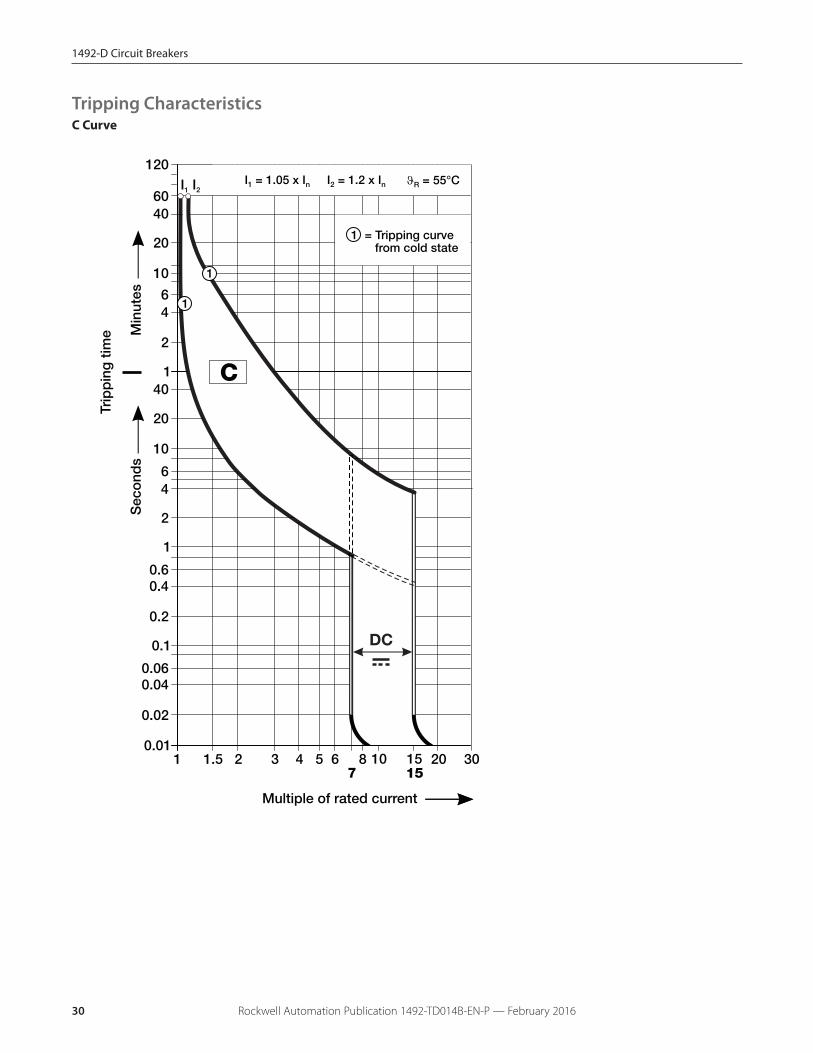
Rockwell Automation Publication 1492-TD014B-EN-P — February 201630
C CurveTripping Characteristics
1492-D Circuit Breakers
Rockwell Automation Publication 1492-TD014B-EN-P — February 2016 31
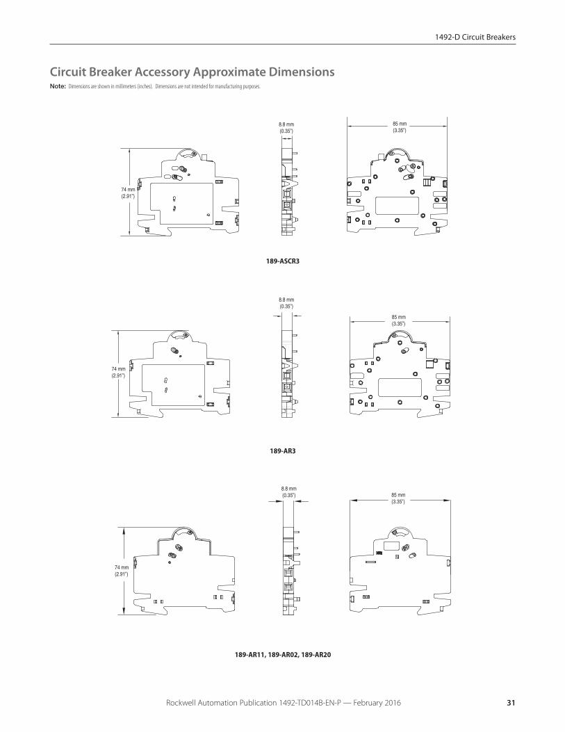
Circuit Breaker Accessory Approximate DimensionsNote: Dimensions are shown in millimeters (inches). Dimensions are not intended for manufacturing purposes.
85 mm(3.35”)
8.8 mm(0.35”)
74 mm(2.91”)
189-ASCR3
85 mm(3.35”)
8.8 mm(0.35”)
74 mm(2.91”)
189-AR3
85 mm(3.35”)
8.8 mm(0.35”)
74 mm(2.91”)
189-AR11, 189-AR02, 189-AR20
1492-D Circuit Breakers
Rockwell Automation Publication 1492-TD014B-EN-P — February 201632
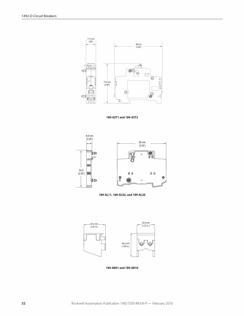
189-AST1 and 189-AST2
189-AL11, 189-AL02, and 189-AL20
46.4 mm(1.83 in.)
34.8 mm(1.37 in.)
42.4 mm(1.67 in.)
189-AB01 and 189-AB10
17.5 mm(.69”)
88 mm(3.46”)
73.3 mm(2.86”)
8.8 mm(0.35”)
64.2(2.53”)
85 mm(3.35”)
1492-D Circuit Breakers
Rockwell Automation Publication 1492-TD014B-EN-P — February 2016 33
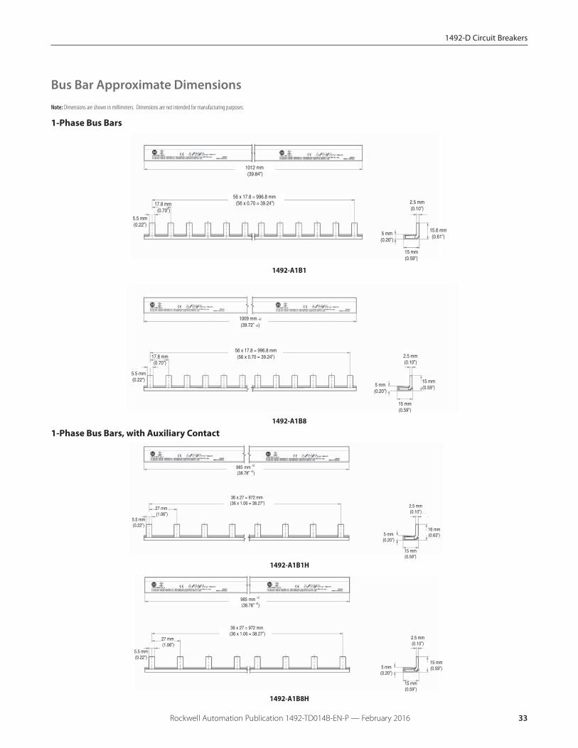
Bus Bar Approximate Dimensions
Note: Dimensions are shown in millimeters. Dimensions are not intended for manufacturing purposes.
1-Phase Bus Bars
1012 mm (39.84”)
56 x 17.8 = 996.8 mm (56 x 0.70 = 39.24”)
5.5 mm(0.22”)
17.8 mm (0.70”)
15 mm(0.59”)
15.6 mm(0.61”)
2.5 mm(0.10”)
5 mm(0.20”)
1492-A1B1
1009 mm +2
(39.72” +2)
5.5 mm(0.22”)
17.8 mm(0.70”)
56 x 17.8 = 996.8 mm(56 x 0.70 = 39.24”)
5 mm(0.20”)
2.5 mm(0.10”)
15 mm(0.59”)
15 mm(0.59”)
1492-A1B8
1-Phase Bus Bars, with Auxiliary Contact
5.5 mm(0.22”)
27 mm (1.06”)
15 mm(0.59”)
2.5 mm(0.10”)
16 mm(0.63”)
985 mm +2 (38.78” +2)
5 mm(0.20”)
36 x 27 = 972 mm (36 x 1.06 = 38.27”)
1492-A1B1H
5.5 mm(0.22”)
27 mm (1.06”)
15 mm(0.59”)
2.5 mm(0.10”)
15 mm(0.59”)
985 mm +2 (38.78” +2)
5 mm(0.20”)
36 x 27 = 972 mm (36 x 1.06 = 38.27”)
1492-A1B8H
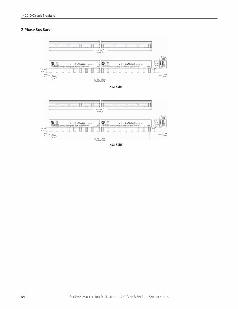
2-Phase Bus Bars
1492-A2B1
13.5 mm(0.53”)
6 mm (0.23”)
21.2 mm(0.83”)
991 mm +2 (39.02” +2)
17.8 mm (0.70”) 55 x 17.8 = 979 mm
(55x 0.70 = 38.54”)
36.5 mm(1.44”)
23 mm(0.91”)
1.5 mm(0.06”)
13.5 mm(0.53”)
6 mm (0.23”)
21.2 mm(0.83”)
991 mm +2 (39.02” +2)
17.8 mm (0.70”) 55 x 17.8 = 979 mm
(55x 0.70 = 38.54”)
36.5 mm(1.44”)
23 mm(0.91”)
1.5 mm(0.06”)
1492-A2B8
34 Rockwell Automation Publication 1492-TD014B-EN-P — February 2016
1492-D Circuit Breakers
1492-D Circuit Breakers
2-Phase Bus Bars, with Auxiliary Contact
17.8 mm (0.70”)
1009 mm +2 (39.72” +2)
22 x 44 = 968 mm (22 x 1.73 = 38.11”)
44 mm (1.73”)
21.2 mm(0.83”)
36.5 mm(1.44”)
23 mm(0.91”)
2 mm(0.08”)
13.5 mm(0.53”)
6 mm(0.24”)
1492-A2B1H
17.8 mm (0.70”)
1009 mm +2 (39.72” +2)
22 x 44.5 = 979 mm (22 x 1.75 = 38.5”)
44.5 mm (1.75”)
21.2 mm(0.83”)
36.5 mm(1.44”)
23 mm(0.91”)
2 mm(0.08”)
13.5 mm(0.53”)
6 mm(0.24”)
1492-A2B8H
35Rockwell Automation Publication 1492-TD014B-EN-P — February 2016

1492-AAT1LP
1492-AAT1S
1492-AAT2
5 mm(0.20”)
14 mm(0.55”)
8.5 mm(0.33”)
1 mm(0.04”)
1492-A1E
21.6 mm(0.85”)
9.5 mm(0.37”)
24 mm(0.95”)
1492-AME
85.2 mm(3.35”)
1492-AAP
36 Rockwell Automation Publication 1492-TD014B-EN-P — February 2016
1492-D Circuit Breakers
188 Regional Circuit Breakers
Rockwell Automation Publication 1492-TD014B-EN-P — February 2016 37
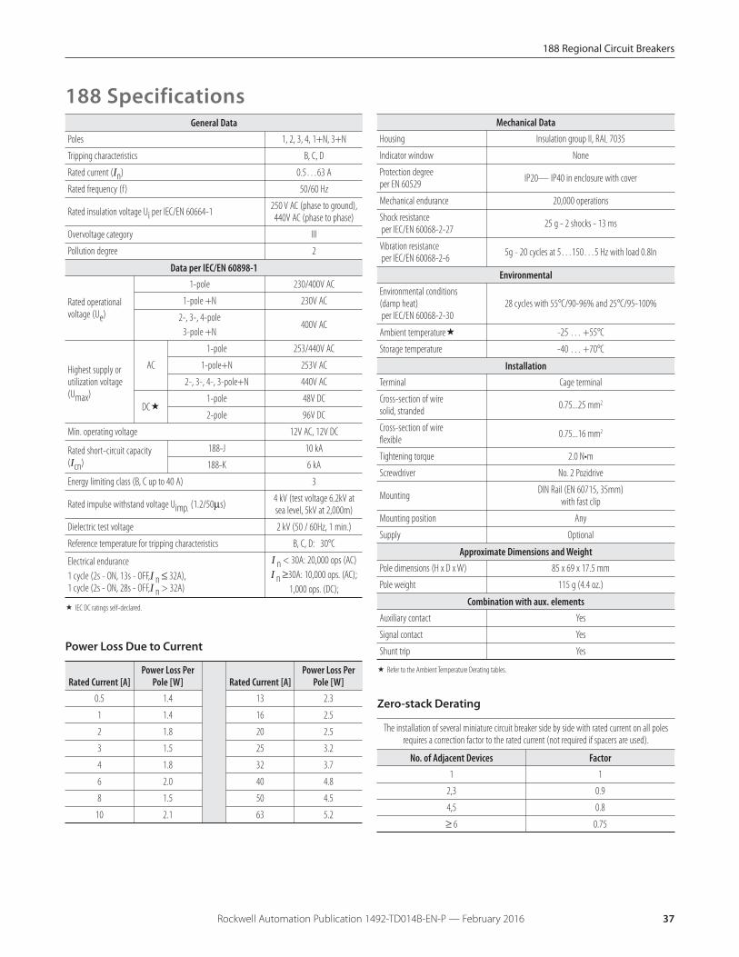
188 SpecificationsMechanical Data
Housing Insulation group II, RAL 7035
Indicator window None
Protection degreeper EN 60529 IP20— IP40 in enclosure with cover
Mechanical endurance 20,000 operations
Shock resistanceper IEC/EN 60068-2-27 25 g - 2 shocks - 13 ms
Vibration resistanceper IEC/EN 60068-2-6 5g - 20 cycles at 5…150…5 Hz with load 0.8In
EnvironmentalEnvironmental conditions(damp heat)per IEC/EN 60068-2-30
28 cycles with 55°C/90-96% and 25°C/95-100%
Ambient temperature� -25 … +55°C
Storage temperature -40 … +70°C
InstallationTerminal Cage terminal
Cross-section of wiresolid, stranded 0.75...25 mm2
Cross-section of wireflexible 0.75...16 mm2
Tightening torque 2.0 N•m
Screwdriver No. 2 Pozidrive
Mounting DIN Rail (EN 60715, 35mm)with fast clip
Mounting position Any
Supply Optional
Approximate Dimensions and WeightPole dimensions (H x D x W) 85 x 69 x 17.5 mm
Pole weight 115 g (4.4 oz.)
Combination with aux. elementsAuxiliary contact Yes
Signal contact Yes
Shunt trip Yes
� Refer to the Ambient Temperature Derating tables.
General DataPoles 1, 2, 3, 4, 1+N, 3+N
Tripping characteristics B, C, D
Rated current (In) 0.5…63 A
Rated frequency (f ) 50/60 Hz
Rated insulation voltage Ui per IEC/EN 60664-1 250 V AC (phase to ground),440V AC (phase to phase)
Overvoltage category III
Pollution degree 2
Data per IEC/EN 60898-1
Rated operationalvoltage (Ue)
1-pole 230/400V AC
1-pole +N 230V AC
2-, 3-, 4-pole3-pole +N
400V AC
Highest supply orutilization voltage(Umax)
AC
1-pole 253/440V AC
1-pole+N 253V AC
2-, 3-, 4-, 3-pole+N 440V AC
DC�1-pole 48V DC
2-pole 96V DC
Min. operating voltage 12V AC, 12V DC
Rated short-circuit capacity(Icn)
188-J 10 kA
188-K 6 kA
Energy limiting class (B, C up to 40 A) 3
Rated impulse withstand voltage Uimp. (1.2/50μs) 4 kV (test voltage 6.2kV atsea level, 5kV at 2,000m)
Dielectric test voltage 2 kV (50 / 60Hz, 1 min.)
Reference temperature for tripping characteristics B, C, D: 30°C
Electrical endurance1 cycle (2s - ON, 13s - OFF,I n ≤ 32A),1 cycle (2s - ON, 28s - OFF,I n > 32A)
I n < 30A: 20,000 ops (AC) I n ≥30A: 10,000 ops. (AC);
1,000 ops. (DC);
� IEC DC ratings self-declared.
Power Loss Due to Current
Rated Current [A]Power Loss Per
Pole [W] Rated Current [A]Power Loss Per
Pole [W]0.5 1.4 13 2.3
1 1.4 16 2.5
2 1.8 20 2.5
3 1.5 25 3.2
4 1.8 32 3.7
6 2.0 40 4.8
8 1.5 50 4.5
10 2.1 63 5.2
Zero-stack Derating
The installation of several miniature circuit breaker side by side with rated current on all polesrequires a correction factor to the rated current (not required if spacers are used).
No. of Adjacent Devices Factor1 1
2,3 0.9
4,5 0.8
≥ 6 0.75
188 Regional Circuit Breakers
Rockwell Automation Publication 1492-TD014B-EN-P — February 201638
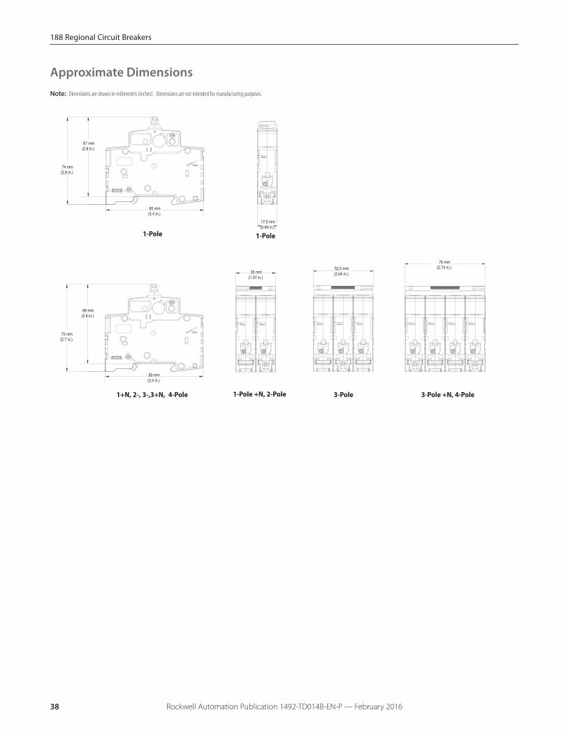
Note: Dimensions are shown in millimeters (inches). Dimensions are not intended for manufacturing purposes.
85 mm(3.4 in.)
67 mm(2.6 in.)
74 mm(2.9 in.)
35 mm(1.37 in.)
52.5 mm(2.04 in.)
70 mm(2.74 in.)
17.5 mm(0.69 in.)
85 mm(3.4 in.)
69 mm(2.6 in.)
75 mm(2.7 in.)
1-Pole
1+N, 2-, 3-,3+N, 4-Pole 1-Pole +N, 2-Pole 3-Pole
1-Pole
3-Pole +N, 4-Pole
Approximate Dimensions
188 Regional Circuit Breakers
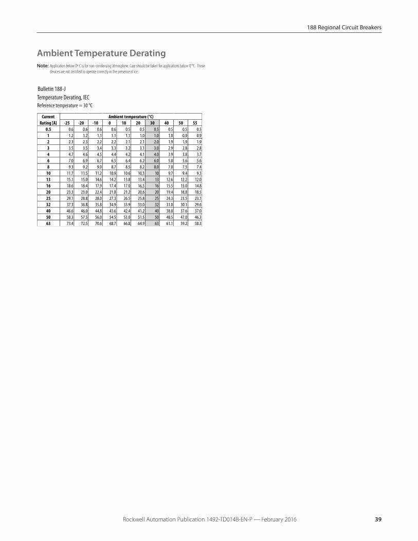
Rockwell Automation Publication 1492-TD014B-EN-P — February 2016 39
Ambient Temperature DeratingNote: Application below 0º C is for non-condensing atmosphere. Care should be taken for applications below 0 °C. These
devices are not certified to operate correctly in the presence of ice.
Reference temperature = 30 °CTemperature Derating, IEC
Bulletin 188-J
-25 -20 -10 0 10 20 30 40 50 550.5 0.6 0.6 0.6 0.6 0.5 0.5 0.5 0.5 0.5 0.5
1 1.2 1.2 1.1 1.1 1.1 1.0 1.0 1.0 0.9 0.92 2.3 2.3 2.2 2.2 2.1 2.1 2.0 1.9 1.9 1.93 3.5 3.5 3.4 3.3 3.2 3.1 3.0 2.9 2.8 2.84 4.7 4.6 4.5 4.4 4.2 4.1 4.0 3.9 3.8 3.76 7.0 6.9 6.7 6.5 6.4 6.2 6.0 5.8 5.6 5.68 9.3 9.2 9.0 8.7 8.5 8.2 8.0 7.8 7.5 7.4
10 11.7 11.5 11.2 10.9 10.6 10.3 10 9.7 9.4 9.313 15.1 15.0 14.6 14.2 13.8 13.4 13 12.6 12.2 12.016 18.6 18.4 17.9 17.4 17.0 16.5 16 15.5 15.0 14.820 23.3 23.0 22.4 21.8 21.2 20.6 20 19.4 18.8 18.525 29.1 28.8 28.0 27.3 26.5 25.8 25 24.3 23.5 23.132 37.3 36.8 35.8 34.9 33.9 33.0 32 31.0 30.1 29.640 46.6 46.0 44.8 43.6 42.4 41.2 40 38.8 37.6 37.050 58.3 57.5 56.0 54.5 53.0 51.5 50 48.5 47.0 46.363 73.4 72.5 70.6 68.7 66.8 64.9 63 61.1 59.2 58.3
Current Rating [A]
Ambient temperature (°C)
188 Regional Circuit Breakers
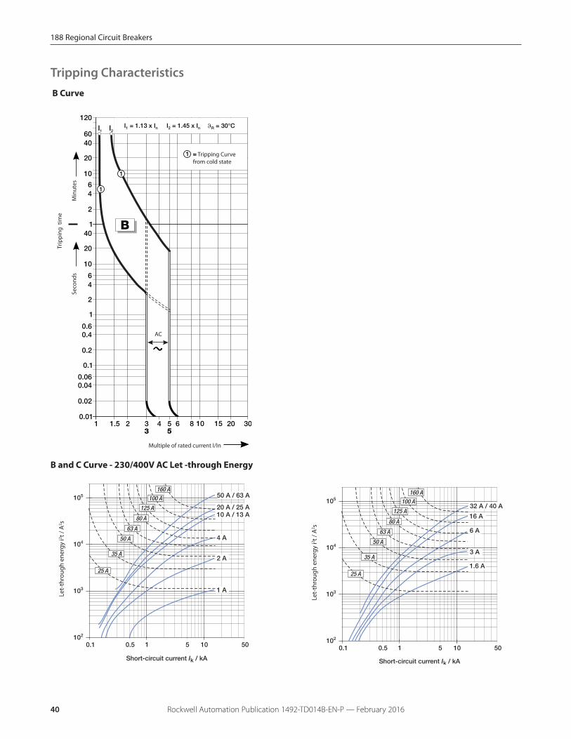
Rockwell Automation Publication 1492-TD014B-EN-P — February 201640
B Curve
= Tripping Curvefrom cold state
Trip
pin
g t
ime
Multiple of rated current I/In
AC
Se
con
ds
Min
ute
s
Let-
thro
ugh
ener
gy i2 t /
A2 s
Let-
thro
ugh
ener
gy i2 t /
A2 s
B and C Curve - 230/400V AC Let -through Energy
Tripping Characteristics
188 Regional Circuit Breakers
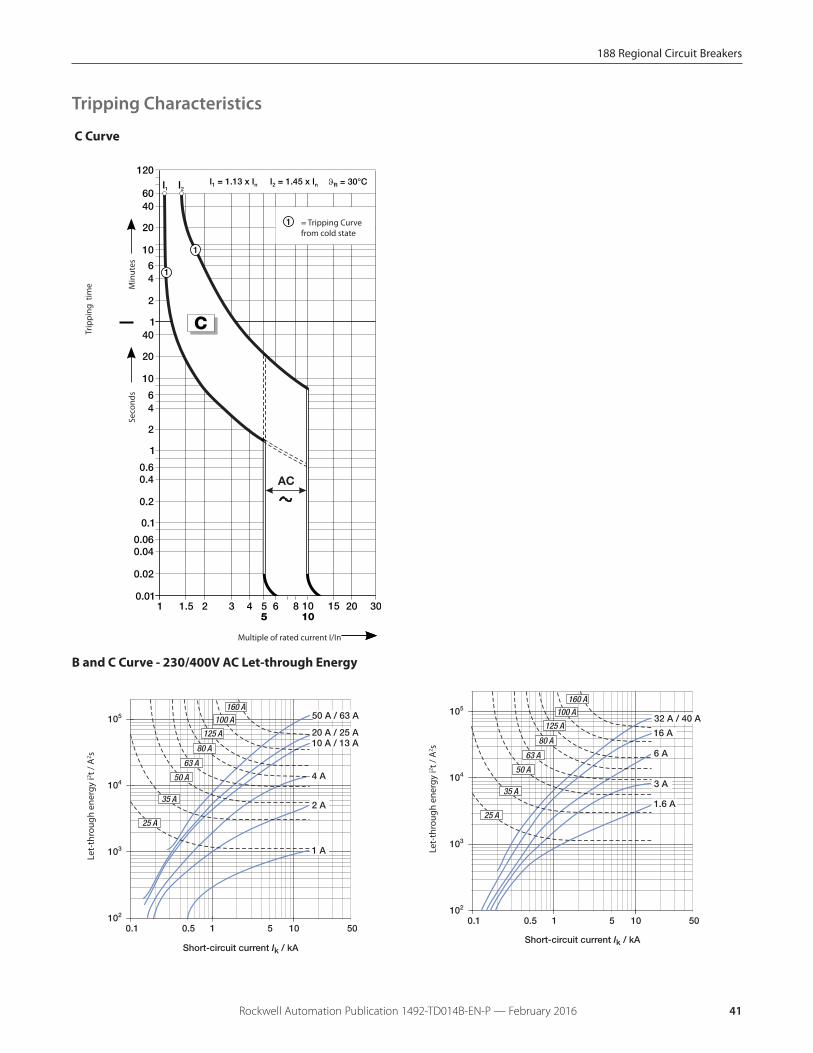
Rockwell Automation Publication 1492-TD014B-EN-P — February 2016 41
Trip
pin
g t
ime
= Tripping Curvefrom cold state
Multiple of rated current I/In
Se
con
ds
Min
ute
s
Let-
thro
ugh
ener
gy i2 t /
A2 s
Let-
thro
ugh
ener
gy i2 t /
A2 s
B and C Curve - 230/400V AC Let-through Energy
C Curve
Tripping Characteristics
188 Regional Circuit Breakers
Rockwell Automation Publication 1492-TD014B-EN-P — February 201642
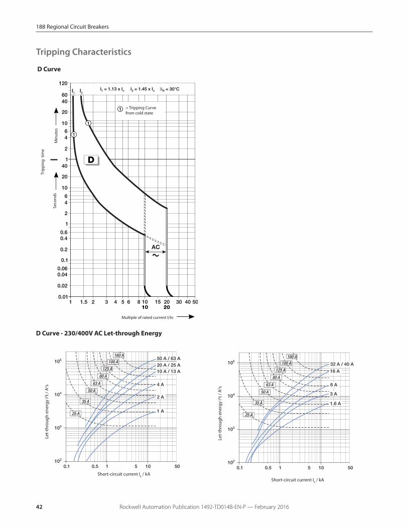
Tripping Characteristics
D Curve
= Tripping Curvefrom cold state
Multiple of rated current I/In
Se
con
ds
Min
ute
s
Trip
pin
g t
ime
Let-
thro
ugh
ener
gy i2 t /
A2 s
Short-circuit current Ik / kA
D Curve - 230/400V AC Let-through Energy
Let-
thro
ugh
ener
gy i2 t /
A2 s
Short-circuit current Ik / kA
188 Regional Circuit Breakers
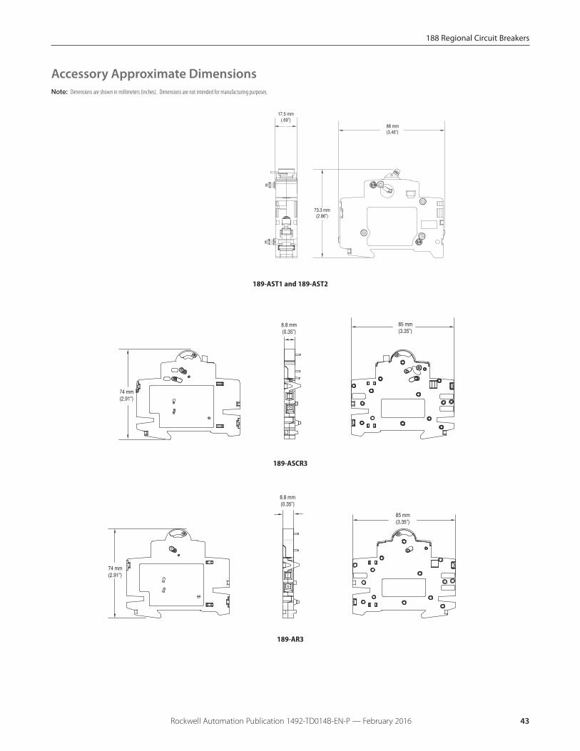
Rockwell Automation Publication 1492-TD014B-EN-P — February 2016 43
Note: Dimensions are shown in millimeters (inches). Dimensions are not intended for manufacturing purposes.
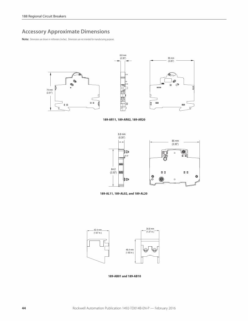
Accessory Approximate Dimensions
85 mm(3.35”)
8.8 mm(0.35”)
74 mm(2.91”)
189-ASCR3
85 mm(3.35”)
8.8 mm(0.35”)
74 mm(2.91”)
189-AR3
189-AST1 and 189-AST2
17.5 mm(.69”)
88 mm(3.46”)
73.3 mm(2.86”)
188 Regional Circuit Breakers
Rockwell Automation Publication 1492-TD014B-EN-P — February 201644
Note: Dimensions are shown in millimeters (inches). Dimensions are not intended for manufacturing purposes.
Accessory Approximate Dimensions
189-AR11, 189-AR02, 189-AR20
85 mm(3.35”)
8.8 mm(0.35”)
74 mm(2.91”)
46.4 mm(1.83 in.)
34.8 mm(1.37 in.)
42.4 mm(1.67 in.)
189-AB01 and 189-AB10
189-AL11, 189-AL02, and 189-AL20
8.8 mm(0.35”)
64.2(2.53”)
85 mm(3.35”)

188 Regional Circuit Breakers
Rockwell Automation Publication 1492-TD014B-EN-P — February 2016 45
Bus Bar Approximate Dimensions
1-Phase Bus Bars
189-CL1
189-CL112
189-CL106 189-CL102
Note: Dimensions are shown in millimeters (inches). Dimensions are not intended for manufacturing purposes.
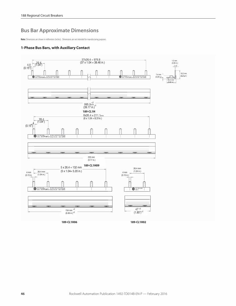
Bus Bar Approximate DimensionsNote: Dimensions are shown in millimeters (inches). Dimensions are not intended for manufacturing purposes.
1-Phase Bus Bars, with Auxiliary Contact
(37 x 1.04 = 38.46 in.)(1.04”)
(0.15”)
(39.17 in.)+2
(8 x 1.04 = 8.31in.)(1.04”)
(0.15”)
+2
(1.85”)+2
18.2 mm(0.71 in.)
20.2 mm(0.80 in.)
7.4 mm(0.29 in.)
1.5 mm (0.06 in.)
mm
mm
26.4 mm(1.04 in.) 4 mm
(0.15 in.) 4 mm(0.15 in.)
26.4 mm(1.04 in.)
154 mm(6.06 in.)
+2
+2
5 x 26.4 = 132 mm(5 x 1.04= 5.20 in.)
233 mm(9.17 in.)
189-CL1H
189-CL1H09
189-CL1H06 189-CL1H02
46 Rockwell Automation Publication 1492-TD014B-EN-P — February 2016
188 Regional Circuit Breakers
188 Regional Circuit Breakers
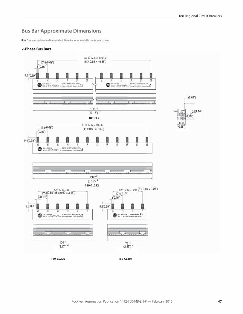
Bus Bar Approximate Dimensions
57 X 17.6 = 1003.2(5 X 0.69 = 40.88”)(0.69”)
(0.16”)
(0.39”)
(40.16”) +2
(11 x 0.69 = 7.62”)(0.69”)(0.16”)
(0.39”)
(8.35”) +2
(0.69”)(0.16”)
(0.39”)
(5 x 0.69 = 3.46”)
(4.17”) +2 (2.83”) +2
(0.69”)(0.16”)
(0.39”)
(3 x 0.69 = 2.06”)
(1.14”)
(0.76”)
(0.04”)
(0.58”)
189-CL2
189-CL212
189-CL206 189-CL204
Note: Dimensions are shown in millimeters (inches). Dimensions are not intended for manufacturing purposes.
2-Phase Bus Bars
47Rockwell Automation Publication 1492-TD014B-EN-P — February 2016

Bus Bar Approximate Dimensions
2-Phase Bus Bars, with Auxiliary Contact
4 mm(0.16”)
9.8 mm(0.39”)
9.8 mm(0.39”)
4 mm(0.16”)
17.6 mm(0.69”)
44 mm(1.73”)
17.6 mm(0.69”)
44 mm(1.73”)
21 x 44 = 924 mm(21 x 1.73 = 36.38”)
960 mm +2
(37.80”) +2
4 x 44 = 176 mm(4 x 1.73 = 6.92”)
210 mm +2
(8.26”) +2
4 mm(0.16”)
9.8 mm(0.39”)
17.6 mm(0.69”)
44 mm(1.73”)
2 x 44 = 88 mm(2 x 1.73 = 3.46”)
4 mm(0.16”)
9.8 mm(0.39”)
17.6 mm(0.69”)
44 mm(1.73”)
124 mm +2
(4.88”) +280 mm +2
(3.14”) +2
1 mm(0.04”)
29 mm(1.14”)
19.2 mm(0.76”)
14.8 mm(0.58”)189-CL2H
189-CL2H10
189-CL2H06 189-CL2H04
Note: Dimensions are shown in millimeters (inches). Dimensions are not intended for manufacturing purposes.
48 Rockwell Automation Publication 1492-TD014B-EN-P — February 2016
188 Regional Circuit Breakers
188 Regional Circuit Breakers
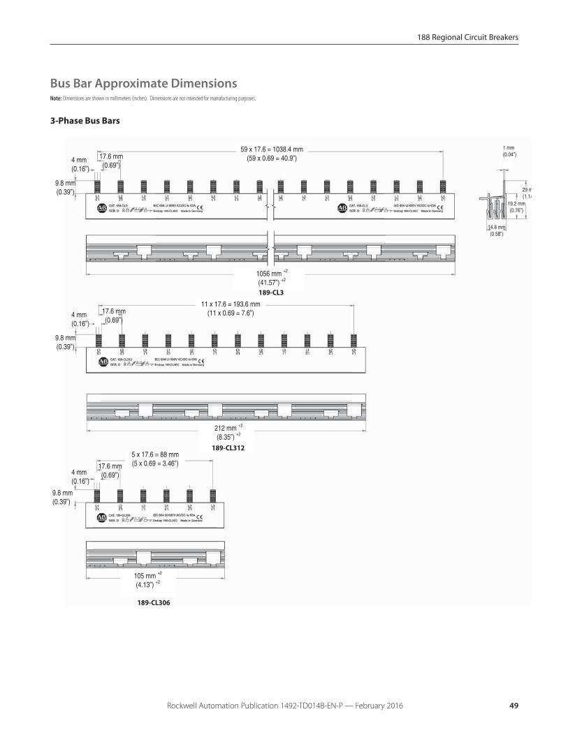
Bus Bar Approximate Dimensions
3-Phase Bus Bars
212 mm +2
(8.35”) +2
4 mm(0.16”)
9.8 mm(0.39”)
17.6 mm(0.69”)
5 x 17.6 = 88 mm(5 x 0.69 = 3.46”)
105 mm +2
(4.13”) +2
1 mm(0.04”)
29 m(1.14
19.2 mm(0.76”)
14.8 mm(0.58”)
11 x 17.6 = 193.6 mm(11 x 0.69 = 7.6”)4 mm
(0.16”)
9.8 mm(0.39”)
17.6 mm(0.69”)
1056 mm +2
(41.57”) +2
59 x 17.6 = 1038.4 mm(59 x 0.69 = 40.9”)4 mm
(0.16”)
9.8 mm(0.39”)
17.6 mm(0.69”)
189-CL3
189-CL312
189-CL306
Note: Dimensions are shown in millimeters (inches). Dimensions are not intended for manufacturing purposes.
49Rockwell Automation Publication 1492-TD014B-EN-P — February 2016
Bus Bar Approximate Dimensions
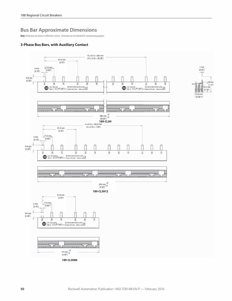
3-Phase Bus Bars, with Auxiliary Contact
4 mm(0.16”)
980 mm +2
(38.60”) +2
1 mm(0.04”)
14.8 mm(0.58”)
15 x 61.6 = 924 mm(15 x 2.43 = 36.38”)
9.8 mm(0.39”)
17.6 mm(0.69”)
61.6 mm(2.43”)
4 mm(0.16”)
240 mm +2
(9.48”) +2
4 x 61.6 = 184.8 mm(4 x 2.43 = 7.28”)
9.8 mm(0.39”)
17.6 mm(0.69”)
61.6 mm(2.43”)
4 mm(0.16”)
9.8 mm(0.39”)
17.6 mm(0.69”)
61.6 mm(2.43”)
114 mm +2
(4.49”) +2
19.2 mm(0.76”)
29 mm(1.14”)
189-CL3H
189-CL3H12
189-CL3H06
Note: Dimensions are shown in millimeters (inches). Dimensions are not intended for manufacturing purposes.
50 Rockwell Automation Publication 1492-TD014B-EN-P — February 2016
188 Regional Circuit Breakers
188 Regional Circuit Breakers
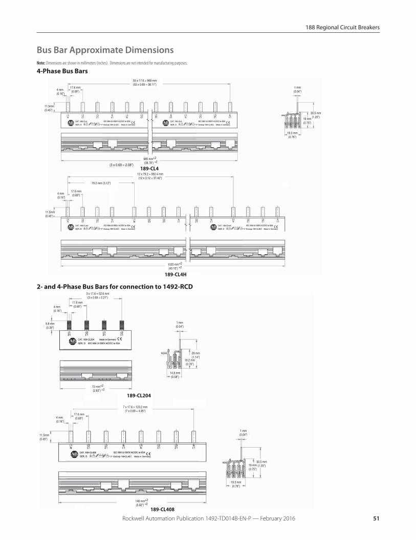
4-Phase Bus Bars
Bus Bar Approximate Dimensions
2- and 4-Phase Bus Bars for connection to 1492-RCD
(3 x 0.69 = 2.08”)
985 mm+2
(38.78”) +2
4 mm(0.16”)
11.5mm(0.45”)
17.6 mm(0.69”)
55 x 17.6 = 968 mm(55 x 0.69 = 38.11”)
4 mm(0.16”)
11.5mm(0.45”)
17.6 mm(0.69”)
79.2 mm (3.12”)
12 x 79.2 = 950.4 mm(12 x 3.12 = 37.42”)
1020 mm+2
(40.15”) +2
1 mm(0.04”)
19.3 mm(0.76”)
30.5 mm(1.20”)19 mm
(0.75”)
189-CL4
189-CL4H
4 mm(0.16”)
11.5mm(0.45”)
17.6 mm(0.69”)
1 mm(0.04”)
19.3 mm(0.76”)
30.5 mm(1.20”)19 mm
(0.75”)
7 x 17.6 = 123.2 mm(7 x 0.69 = 4.85”)
148 mm+2
(5.82”) +2
4 mm(0.16”)
9.8 mm(0.39”)
17.6 mm(0.69”)
3 x 17.6 = 52.6 mm(3 x 0.69 = 2.21”)
72 mm+2
(2.83”) +2
1 mm(0.04”)
14.8 mm(0.58”)
19.2 mm(0.76”)
29 mm(1.14”)
189-CL204
189-CL408
Note: Dimensions are shown in millimeters (inches). Dimensions are not intended for manufacturing purposes.
51Rockwell Automation Publication 1492-TD014B-EN-P — February 2016
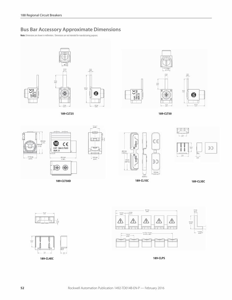
5 mm(0.20 in.)
10.5 mm(0.41 in.)
48.9 mm(1.93 in.)
22 mm(0.87 in.)
13.8 mm(0.55”)
17 mm(0.67”)
3.5 mm(0.14”)
23.7 mm(0.93”)
8 mm(0.31”)
7 mm(0.27”)
4.3 mm(0.17”)
15 mm(0.59”)
13 mm(0.51”)
2 mm(0.08”)
32.5mm(1.28”)
16.5 mm(0.65”)
4.3 mm(0.16”)
15 mm(0.59”)
13 mm(0.65”)
2 mm(0.08”)
35 mm(1.38”)
25.6 mm(1.01”)
11 mm(0.43”)
28.8 mm(1.13”)
17.75 mm(0.70”)
12.3 mm(0.48”)
10.5 mm(0.41”)
35.3 mm(1.39”)
29.8 mm(1.17”)
13.5 mm(0.53”)
4.3 mm(0.17”)
84.7 mm(3.33”)
17.8 mm(0.70”)
18.5 mm(0.73”)
4.2 mm(0.17”)
11.6 mm(0.46”)4 x 17.8 = 71.2 mm
(4 x 0.70 = 2.80”)
12 mm(0.47”)
13.9 mm(0.55”)
18 mm(0.71”)
3.6 mm(0.14”)
Bus Bar Accessory Approximate DimensionsNote: Dimensions are shown in millimeters. Dimensions are not intended for manufacturing purposes.
189-CL1EC 189-CL3EC
189-CL4EC
189-CLT25 189-CLT50
189-CLT50D
189-CLPS
52 Rockwell Automation Publication 1492-TD014B-EN-P — February 2016
188 Regional Circuit Breakers
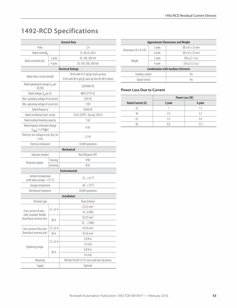
Power Loss Due to Current
Rated Current [A]
Power Loss [W]
2-pole 4-pole25 1 1.3
40 2.4 3.2
63 3.2 4.4
80 8.8 33.3
1492-RCD SpecificationsGeneral Data
Poles 2,4
Rated currentIn 25, 40, 63, 80 A
Rated sensitivity I∆n2-pole 30, 100, 300 mA
4-pole 30, 100, 300, 500 mA
Electrical Ratings
Rated short-circuit strength10 kA with 63 A gG/gL back-up fuse,
10 kA with 80 A gG/gL back-up fuse for 80 A device
Rated operational voltage Ue perIEC/EN 230/400V AC
Rated voltage Ue per UL 480Y/277V AC
Max. operating voltage of circuit test 254V AC
Min. operating voltage of circuit test 110V
Rated frequency 50/60 Hz
Rated conditional short-circuit 10 kA (SCPD - fuse gG 100 A)
Rated residual breaking capacity 1 kA
Rated impulse withstand voltageUimp (1.2/50μs) 4 kV
Dielectric test voltage at ind. freq. for1 min. 2.5 kV
Electrical endurance 10,000 operations
MechanicalIndicator window Red ON/green OFF
Protection degree Housing IP4X
Terminals IP2X
EnvironmentalAmbient temperature
(with daily average +35 °C) -25...+55 °C
Storage temperature -40...+70 °C
Mechanical endurance 20,000 operations
InstallationTerminal type Dual terminal
Cross-section of wire -solid, stranded, flexible
(front/back terminal slot)
25...63 A25/25 mm2
18...4 AWG
80 A35/35 mm2
18…2 AWG
Cross-section of bus bars(front/back terminal slot)
25...63 A 10/10 mm2
80 A 16/16 mm2
Tightening torque
25...63 A2.8 N·m
25 in·lb
80 A4.8 N·m
43 in·lb
Mounting DIN Rail EN 60715 (35 mm) with fast clip device
Supply Optional
Approximate Dimensions and Weight
Dimensions (H x D x W)2-pole 88 x 67 x 35 mm
4-pole 88 x 67 x 70 mm
Weight2-pole 200 g (7.1 oz.)
4-pole 350 g (12.3 oz.)
Combination with Auxiliary ElementsAuxiliary contact Yes
Signal contact Yes
53Rockwell Automation Publication 1492-TD014B-EN-P — February 2016
1492-RCD Residual Current Devices
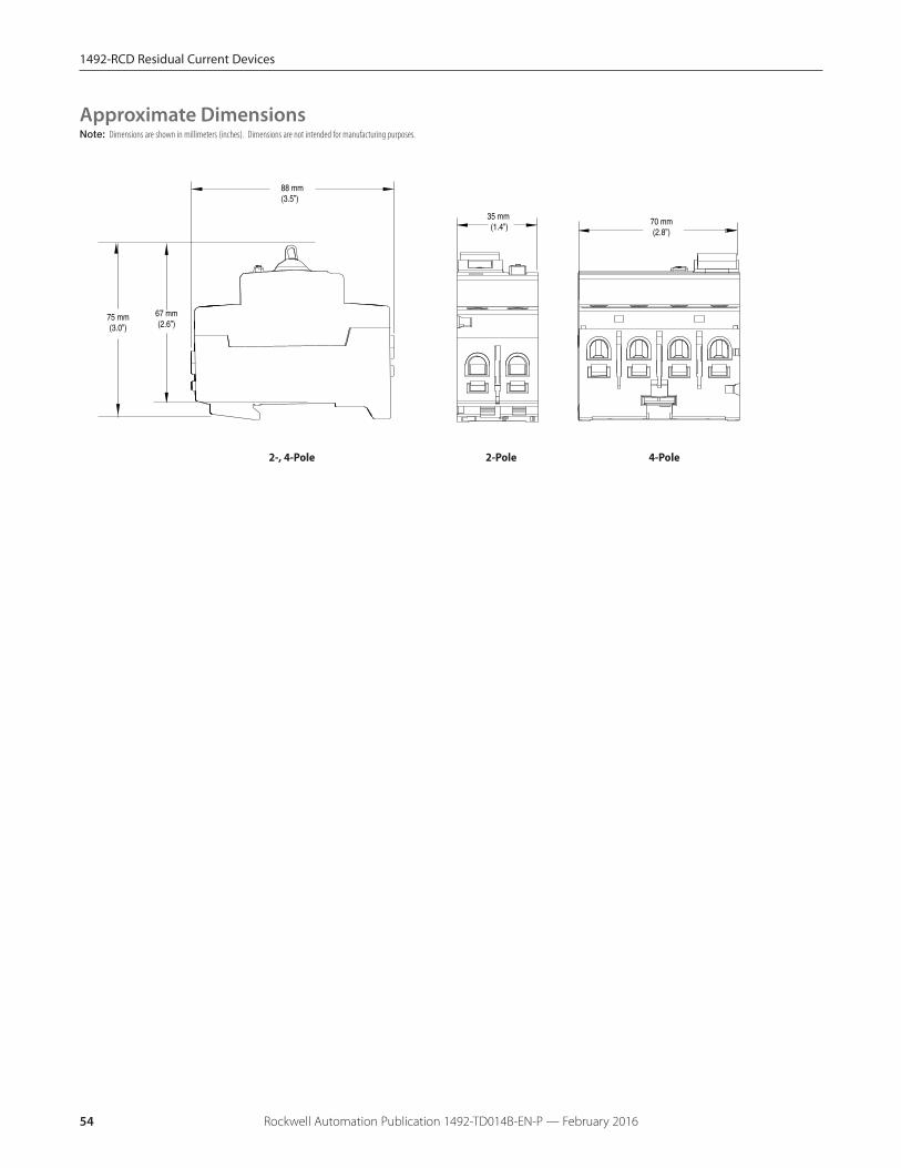
Note: Dimensions are shown in millimeters (inches). Dimensions are not intended for manufacturing purposes.
35 mm (1.4”)
88 mm(3.5”)
67 mm(2.6”)
75 mm(3.0”)
70 mm(2.8”)
2-Pole 4-Pole
Approximate Dimensions
2-, 4-Pole
54 Rockwell Automation Publication 1492-TD014B-EN-P — February 2016
1492-RCD Residual Current Devices
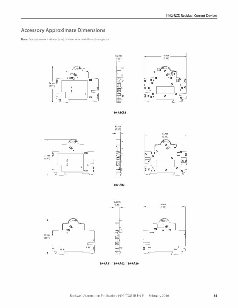
Note: Dimensions are shown in millimeters (inches). Dimensions are not intended for manufacturing purposes.
Accessory Approximate Dimensions
85 mm(3.35”)
8.8 mm(0.35”)
74 mm(2.91”)
189-ASCR3
85 mm(3.35”)
8.8 mm(0.35”)
74 mm(2.91”)
189-AR3
189-AR11, 189-AR02, 189-AR20
85 mm(3.35”)
8.8 mm(0.35”)
74 mm(2.91”)
55Rockwell Automation Publication 1492-TD014B-EN-P — February 2016
1492-RCD Residual Current Devices

Bus Bar Approximate DimensionsNote: Dimensions are shown in millimeters (inches). Dimensions are not intended for manufacturing purposes.
2- and 4-Phase Bus Bars
4 mm(0.16”)
11.5mm(0.45”)
17.6 mm(0.69”)
1 mm(0.04”)
19.3 mm(0.76”)
30.5 mm(1.20”)19 mm
(0.75”)
7 x 17.6 = 123.2 mm(7 x 0.69 = 4.85”)
148 mm+2
(5.82”) +2
4 mm(0.16”)
9.8 mm(0.39”)
17.6 mm(0.69”)
3 x 17.6 = 52.6 mm(3 x 0.69 = 2.21”)
72 mm+2
(2.83”) +2
1 mm(0.04”)
14.8 mm(0.58”)
19.2 mm(0.76”)
29 mm(1.14”)
189-CL204
189-CL408
56 Rockwell Automation Publication 1492-TD014B-EN-P — February 2016
1492-RCD Residual Current Devices
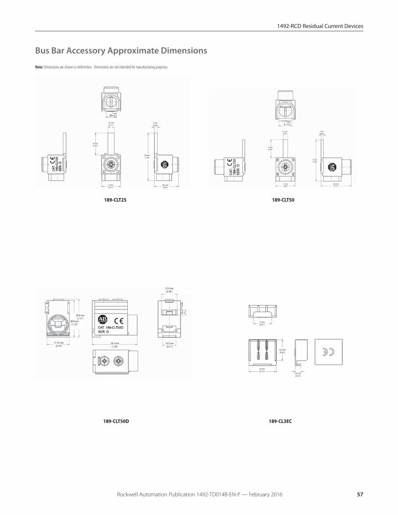
1492-RCD Residual Current Devices
12 mm(0.47”)
13.9 mm(0.55”)
18 mm(0.71”)
3.6 mm(0.14”)
7 mm(0.27”)
4.3 mm(0.17”)
15 mm(0.59”)
13 mm(0.51”)
2 mm(0.08”)
32.5mm(1.28”)
16.5 mm(0.65”)
4.3 mm(0.16”)
15 mm(0.59”)
13 mm(0.65”)
2 mm(0.08”)
35 mm(1.38”)
25.6 mm(1.01”)
11 mm(0.43”)
28.8 mm(1.13”)
17.75 mm(0.70”)
12.3 mm(0.48”)
10.5 mm(0.41”)
35.3 mm(1.39”)
29.8 mm(1.17”)
189-CL3EC
189-CLT25 189-CLT50
189-CLT50D
Bus Bar Accessory Approximate Dimensions
Note: Dimensions are shown in millimeters. Dimensions are not intended for manufacturing purposes.
57Rockwell Automation Publication 1492-TD014B-EN-P — February 2016
1492-RCD Residual Current Devices
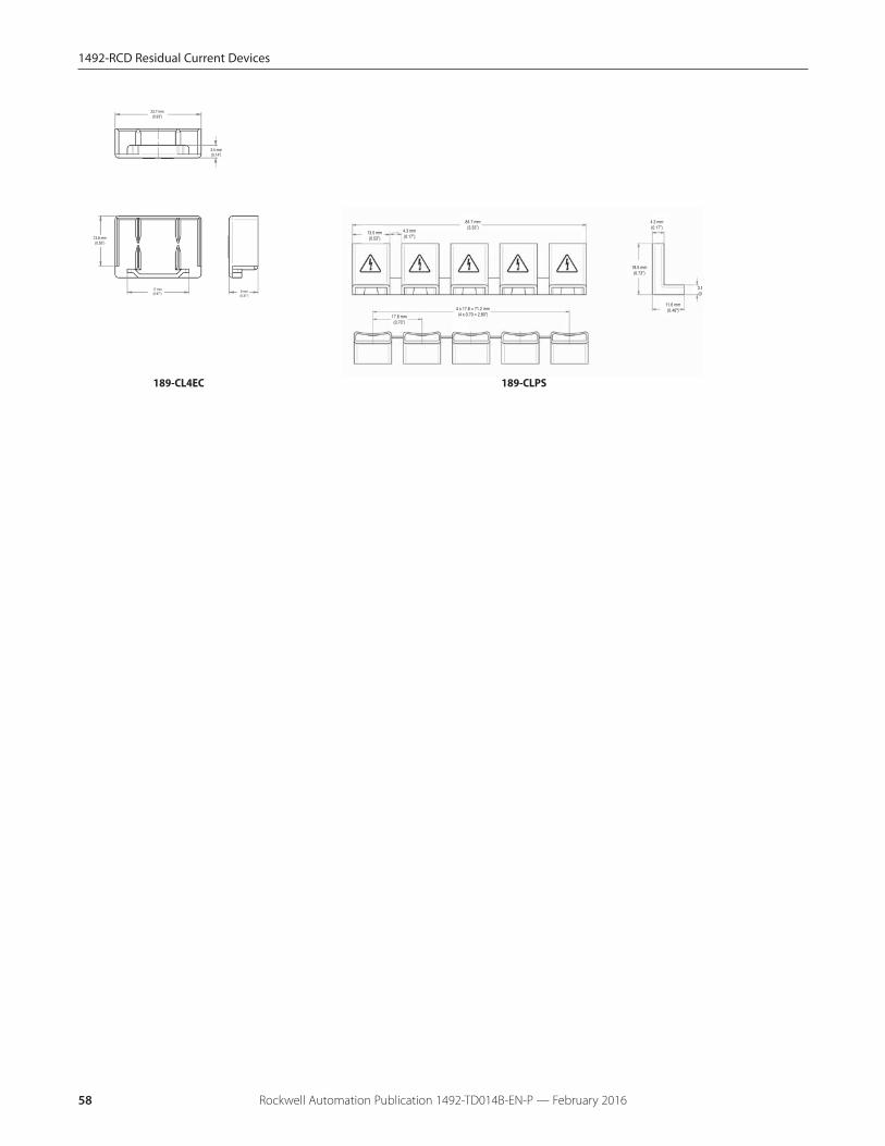
Rockwell Automation Publication 1492-TD014B-EN-P — February 201658
13.8 mm(0.55”)
17 mm(0.67”)
3.5 mm(0.14”)
23.7 mm(0.93”)
8 mm(0.31”)
13.5 mm(0.53”)
4.3 mm(0.17”)
84.7 mm(3.33”)
17.8 mm(0.70”)
18.5 mm(0.73”)
4.2 mm(0.17”)
11.6 mm(0.46”)
3.5(0.
4 x 17.8 = 71.2 mm(4 x 0.70 = 2.80”)
189-CL4EC 189-CLPS
1692 Electronic Circuit Protectors
Rockwell Automation Publication 1492-TD014B-EN-P — February 2016 59
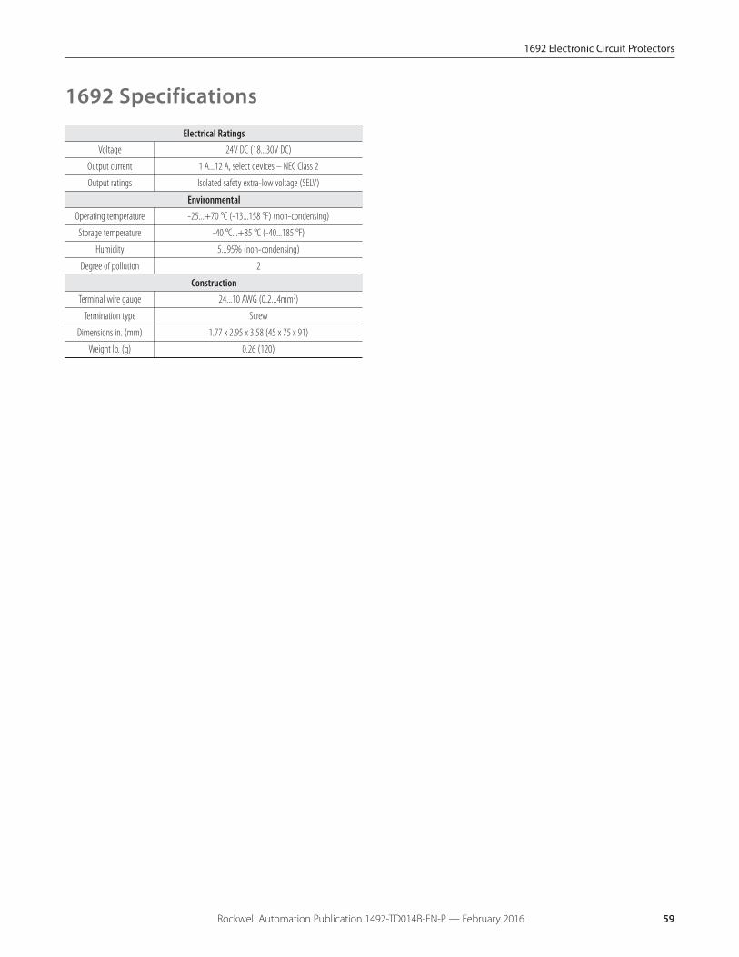
Electrical RatingsVoltage 24V DC (18...30V DC)
Output current 1 A...12 A, select devices – NEC Class 2
Output ratings Isolated safety extra-low voltage (SELV)
EnvironmentalOperating temperature -25...+70 °C (-13...158 °F) (non-condensing)
Storage temperature -40 °C...+85 °C (-40...185 °F)
Humidity 5...95% (non-condensing)
Degree of pollution 2
ConstructionTerminal wire gauge 24...10 AWG (0.2...4mm2)
Termination type Screw
Dimensions in. (mm) 1.77 x 2.95 x 3.58 (45 x 75 x 91)
Weight lb. (g) 0.26 (120)
1692 Specifications

1692 Electronic Circuit Protectors
Rockwell Automation Publication 1492-TD014B-EN-P — February 201660
Signal Connector
Depth: 91 mm, 3.58”
Depth: 104 mm, 4.1”DIN-Raildepth
Hei
ght
: 75
mm
, 2.9
5”
Note: Dimensions are shown in millimeters (inches). Dimensions are not intended for manufacturing purposes.
Approximate Dimensions
1492-MC Circuit Breakers
Rockwell Automation Publication 1492-TD014B-EN-P — February 2016 61
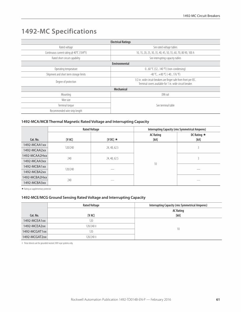
Electrical RatingsRated voltage See rated voltage tables
Continuous current rating @ 40°C (104°F) 10, 15, 20, 25, 30, 35, 40, 45, 50, 55, 60, 70, 80 90, 100 A
Rated short circuit capability See interrupting capacity tables
EnvironmentalOperating temperature 0...60 °C (32...140 °F) (non-condensing)
Shipment and short term storage limits -40 °C...+80 °C (-40...176 °F)
Degree of protection 1/2 in. wide circuit breakers are finger safe from front per IEC.Terminal covers available for 1 in. wide circuit breaker.
MechanicalMounting DIN rail
Wire size
See terminal tableTerminal torque
Recommended wire strip length
1492-MC Specifications
1492-MCA/MCB Thermal Magnetic Rated Voltage and Interrupting Capacity
Cat. No.
Rated Voltage Interrupting Capacity (rms Symmetrical Amperes)
[V AC] [V DC] �AC Rating
[kA]DC Rating �
[kA]1492-MCAA1xx
120/240 24, 48, 62.5
10
31492-MCAA2xx
1492-MCAA2Hxx240 24, 48, 62.5 3
1492-MCAA3xx
1492-MCBA1xx120/240 — —
1492-MCBA2xx
1492-MCBA2Hxx240 — —
1492-MCBA3xx
�Rating as supplementary protector.
1492-MCE/MCG Ground Sensing Rated Voltage and Interrupting Capacity
Cat. No.
Rated Voltage Interrupting Capacity (rms Symmetrical Amperes)
[V AC]AC Rating
[kA]1492-MCEA1xx 120
101492-MCEA2xx 120/240 ‡
1492-MCGAT1xx 120
1492-MCGAT2xx 120/240 ‡
‡ These devices are for grounded neutral 240V wye systems only.
Branch Circuits:
Bulletin 1492-MC circuit breakers may be used to protectbranch circuits. A branch circuit is the wiring portion of asystem extending beyond the final overcurrent deviceprotecting the circuit.
Guidelines established in NEC, CEC, UL, and CSA should beused to determine the specific device. The examples onpage , also apply to the 1492-MC devices.
Coordinated Overcurrent Protection
Where an orderly shutdown is required to minimize thehazards to personnel and equipment, a system ofcoordination based upon the faulted or overloaded circuit isisolated by selective operation of only the overcurrentprotective device closest to the overcurrent condition.
The user should select devices that meet this requirement.
References: NEC 240.12. Also see CEC.
Self Test Capability (GFCI only)
Per UL 943 (5.16 / 6.30), GFCI devices have built-in self testcapability. The self test is an internal, automated functionrunning in the background. For more information pleaserefer to UL 943 standard.
1492-MC Circuit Breakers
Rockwell Automation Publication 1492-TD014B-EN-P — February 201662
Application Considerations
The selection of a specific ampere rating for a specificapplication is dependent on the type of load and duty cycleand is governed by the National Electric Code (CanadianElectric Code) and UL/CSA. In general the codes require thatovercurrent protection is at the current supply and at pointswhere wire sizes are reduced. In addition the codes state thatconductors be protected according to their current carryingcapacity. There are specific situations that require application
Rockwell Automation Publication 1492-TD014B-EN-P — February 2016
The following discussion is based upon National ElectricCode and UL requirements. Similar considerations areappropriate for Canadian applications.
Circuit Voltage
Bul. 1492-MC circuit breakers are rated by voltage class.Applications should not exceed the listed voltage range (seeTable 1).
Circuit Frequency
Bul. 1492-MC circuit breakers may be applied to frequenciesfrom DC up to 60 Hz without derating. For applicationsabove 60…400 Hz, contact Rockwell Automation withspecific application information for the derating of the circuitbreakers.
Available Short Circuit Current
Bul. 1492-MC circuit breakers should only be applied in thoseapplications in which the available short-circuit (or fault)current is less than or equal to the interrupting rating shownin the Voltage and Interrupting Ratings table.
Continuous Current Rating
Bul. 1492-MC circuit breakers are rated in RMS amperes at a40 °C (104 °F) ambient temperature per UL 489 (CSA 22.2 No.5.1). This temperature is the ambient temperature external toan industrial enclosure. If a circuit breaker is applied in atemperature that exceeds the 40 °C (104 °F) ambient, thenthe circuit breaker should be derated. Contact your localRockwell Automation sales office or Allen-Bradley distributorfor derating information.
Selection of a Bul. 1492-MC circuit breaker with appropriatecircuit protection includes consideration of:
� Circuit voltage� Circuit frequency� Available short circuit current� Continuous current rating� Application considerations� Special operating conditions
Application Information consideration, such as motor circuit, and guidelines for theselection for transformer protection.
Bulletin 1492-MC circuit breakers are "non-100% rated" asdefined by UL 489 Part 7.1.4.2. As such the circuit breaker'srating should be loaded to no more than 80%, if used withcontinuous loads.
1492-MC Circuit Breakers
Rockwell Automation Publication 1492-TD014B-EN-P — February 2016 63
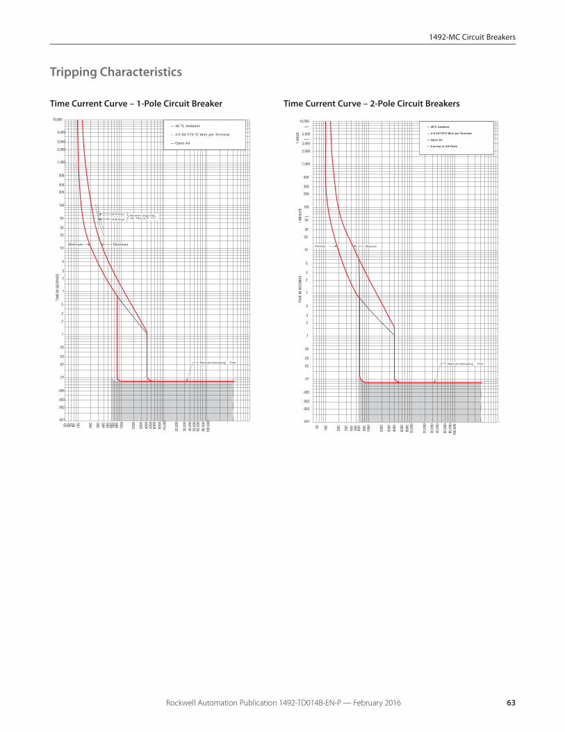
Time Current Curve – 2-Pole Circuit Breakers
Maximum
Maximum Interrupting Time
Minimum
— 40ºC Ambient
— 4 ft 60º/75ºC Wire per Terminal
— Open Air
— Current in All Poles
TIM
E IN
SEC
ONDS
10,000
100
50
30
20
10
5
3
2
1
.5
.3
.2
.1
.05
.03
.02
.01
.005
.003
.002
.001
1,000
500
300
200
5,000
3,000
2,000
1 HO
UR1
MIN
UTE
10,0
0080
0060
00
4000
3000
2000
1000
800
600
500
400
300
200
10050
100,
000
80,0
0060
,000
40,0
0030
,000
20,0
00
Time Current Curve – 1-Pole Circuit Breaker
Maximum
Maximum Interrupting Time
(50-70 Amp)
(10-40 Amp)
— 40 ºC Ambient
— 4 ft 60 º/75 ºC Wire per Terminal
— Open Air
Minimum
TIM
E IN
SEC
ONDS
10,000
100
50
30
20
10
5
3
2
1
.5
.3
.2
.1
.05
.03
.02
.01
.005
.003
.002
.001
1,000
500
300
200
5,000
3,000
2,000
10,0
0080
0060
0050
0040
0030
00
2000
1000
800
600
700
500
400
300
200
100
8060 7050
100,
000
80,0
0060
,000
50,0
0040
,000
30,0
00
20,0
00
Maximum Single-PoleTrip Times at 25 °C➀
Tripping Characteristics
1492-MC Circuit Breakers
Rockwell Automation Publication 1492-TD014B-EN-P — February 201664
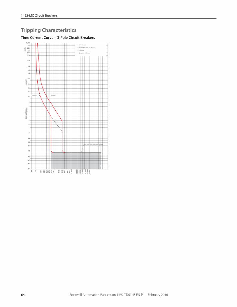
Time Current Curve – 3-Pole Circuit Breakers
TIM
E IN
SEC
ONDS
10,000
100
50
30
20
10
5
3
2
1
.5
.3
.2
.1
.05
.03
.02
.01
.005
.003
.002
.001
1,000
500
300
200
5,000
3,000
2,000
1 HO
UR1
MIN
UTE
10,0
0080
0060
00
4000
3000
2000
1000
800
600
500
400
300
200
10050
100,
000
80,0
0060
,000
40,0
0030
,000
20,0
00
— 40ºC Ambient
— 4 ft 60º/75ºC Wire per Terminal
— Open Air
— Current in All Phases
Maximum Interuppting Time
MaximumMinimum
Tripping Characteristics
1492-MC Circuit Breakers
Rockwell Automation Publication 1492-TD014B-EN-P — February 2016 65
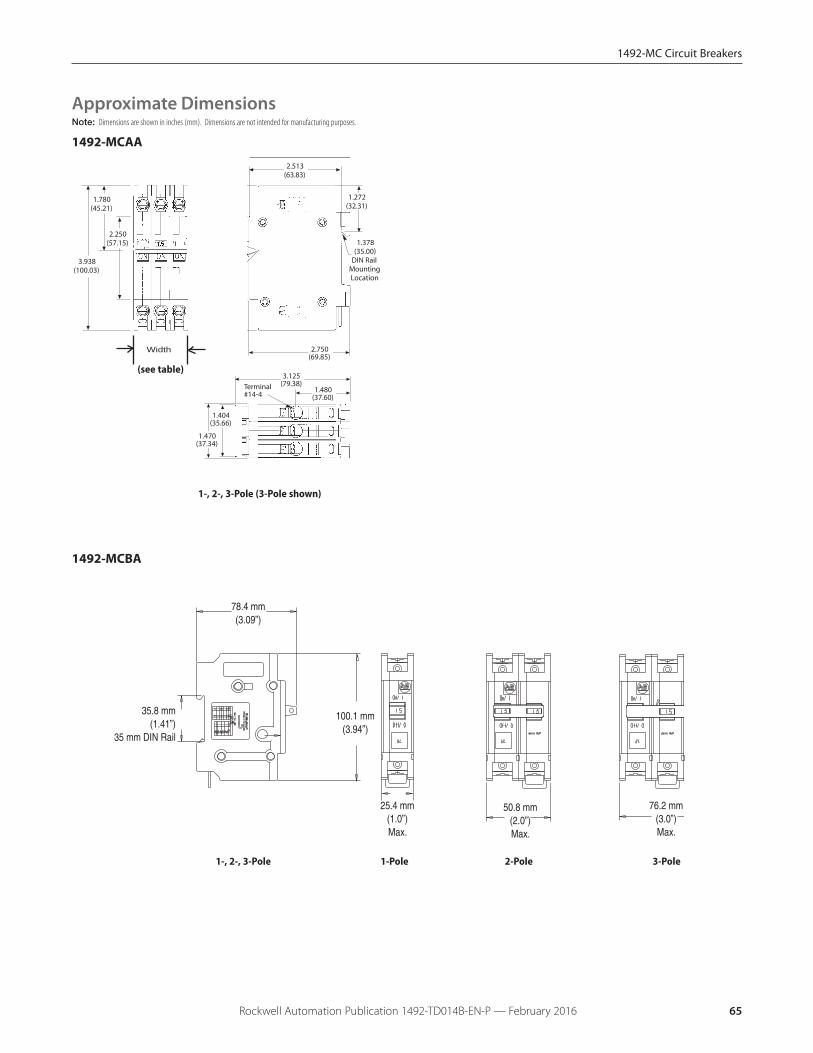
1492-MCAA
2.513(63.83)
0.844(21.44)
0.844(21.44)
2.750(69.85)
0.360(9.14)
18
1824
0.640(16.26)Radius
ResetOff
On
0 Trip
2.250(57.15)
1.780(45.21)
3.938(100.03)
1.470(37.34)
1.404(35.66)
3.125(79.38)
1.480(37.60)
Terminal#14-4
1.272(32.31)
1.378(35.00)
DIN RailMountingLocation
Width
Note: Dimensions are shown in inches (mm). Dimensions are not intended for manufacturing purposes.
Approximate Dimensions
(see table)
1-, 2-, 3-Pole (3-Pole shown)
1492-MCBA
78.4 mm(3.09”)
100.1 mm(3.94”)
35.8 mm(1.41”)
35 mm DIN Rail
25.4 mm(1.0”)Max.
50.8 mm(2.0”)Max.
76.2 mm(3.0”)Max.
1-, 2-, 3-Pole 1-Pole 2-Pole 3-Pole

1492-MC Circuit Breakers
Rockwell Automation Publication 1492-TD014B-EN-P — February 201666
Note: Dimensions are shown in inches. Dimensions are not intended for manufacturing purposes.
0.990 25.15)
2.249 (57.12)
1.240 (31.50)
2.850 (72.39)
0.454 0.562
3.812 (96.82)
18 24
Reset
0 Trip
Ground Neutral Wire Length
24.000 inches (609.60)
Side View
1492-MCE/1492-MCG
Of
182.250(57.15)
0.990(25.15)
1824
Reset
Radius0.578
(14.68
Front View
Radius 0.578
(14.68)
Off
18 2.250 (57.15)
0.990 (25.15)
0.096 (2 44)
18 24
Reset
On
25A thru 50A style
Front View
1.980 (50.29)
2.850 (72.39)
2.500 (63.50)
0.865 (21.97)
Line End View
0.219 (5.56)
1.96(49.53)
Line End View
2.890 (73.41)
1- , 2-Pole
1-Pole 2-Pole
1-Pole 2-Pole
Approximate Dimensions
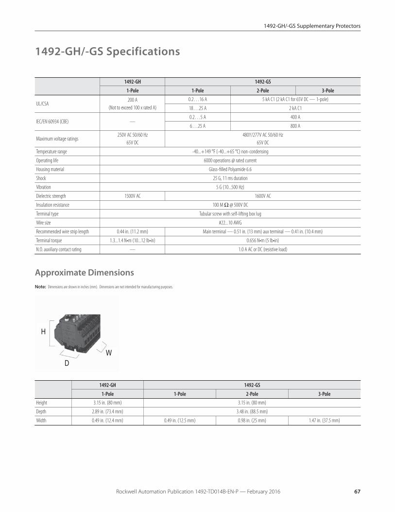
1492-GH/-GS Supplementary Protectors
Rockwell Automation Publication 1492-TD014B-EN-P — February 2016 67
H
DW
1492-GH 1492-GS
1-Pole 1-Pole 2-Pole 3-PoleHeight 3.15 in. (80 mm) 3.15 in. (80 mm)
Depth 2.89 in. (73.4 mm) 3.48 in. (88.5 mm)
Width 0.49 in. (12.4 mm) 0.49 in. (12.5 mm) 0.98 in. (25 mm) 1.47 in. (37.5 mm)
Note: Dimensions are shown in inches (mm). Dimensions are not intended for manufacturing purposes.
1492-GH 1492-GS
1-Pole 1-Pole 2-Pole 3-Pole
UL/CSA200 A
(Not to exceed 100 x rated A)
0.2…16 A 5 kA C1 (2 kA C1 for 65V DC — 1-pole)
18…25 A 2 kA C1
IEC/EN 60934 (CBE) —0.2…5 A 400 A
6…25 A 800 A
Maximum voltage ratings250V AC 50/60 Hz
65V DC480Y/277V AC 50/60 Hz
65V DC
Temperature range -40...+149 °F (-40...+65 °C) non-condensing
Operating life 6000 operations @ rated current
Housing material Glass-filled Polyamide 6.6
Shock 25 G, 11 ms duration
Vibration 5 G (10...500 Hz)
Dielectric strength 1500V AC 1600V AC
Insulation resistance 100 M Ω @ 500V DC
Terminal type Tubular screw with self-lifting box lug
Wire size #22...10 AWG
Recommended wire strip length 0.44 in. (11.2 mm) Main terminal — 0.51 in. (13 mm) aux terminal — 0.41 in. (10.4 mm)
Terminal torque 1.3...1.4 N•m (10...12 lb•in) 0.656 N•m (5 lb•in)
N.O. auxiliary contact rating — 1.0 A AC or DC (resistive load)
1492-GH/-GS Specifications
Approximate Dimensions
1492-GH/-GS Supplementary Protectors
Rockwell Automation Publication 1492-TD014B-EN-P — February 201668
High-density supplementary protector/miniature circuitbreaker applications include, but are not limited to, theprotection of test equipment, control instrumentation,solenoids, and power supplies. The wide range of currentvalues and the use of a thermal magnetic trip system allowsfor a variety of applications where a very accurate andcompact breaker is required.
To select a miniature circuit breaker, use the followingprocedure:
1. Determine the inrush correction factor from the followingtable.
Inrush Ratio Correction TableInrush Ratio 1:1 to 1:4 1:5 1:6 1:7 1:8
Factor 1.3 1.4 1.5 1.6 1.7
Note: For resistive loads use an inrush correction factor of1.0.
2. Determine the temperature correction factor from thefollowing table.
Ambient Temperature Correction Table
AmbientTemperature
70 °F(21.1 °C)
100 °F(37.8 °C)
120 °F(48.9 °C)
140 °F(60 °C)
160 °F(71.1 °C)
180 °F(82.2 °C)
200 °F(93.3 °C)
Factor 1.0 1.1 1.2 1.3 1.4 1.5 1.6
3. Determine the sealed current of the load being protected.
4. Multiply the sealed current by the two correction factorsand select the closest higher ampere rating.
Example — For a solenoid with sealed current of 0.5 A, aninrush ratio of 1:8, and an ambient temperature of +110 °F,(0.5 x 1.7 x 1.15 = 0.9775), select the 1.0 A miniature circuitbreaker. Tripping time of the miniature circuit breaker isdetermined from the table below. Divide the miniaturecircuit breaker value by the temperature correction factorfrom the Ambient Temperature Correction Table todetermine the actual rated current referenced in the tablebelow.
Tripping Times in Seconds at 70 °F (21.1 °C)PercentRatedCurrent
100% 200% 300% 400% 500% 600% 1000%2000%Greater
TrippingTimes(Seconds)
No Trip 10…40 3…18 1.5…9 0.8…6 0.003…4
0.009…2
Max.0.02
Note: When several breakers are rail mounted adjacent toeach other, the no-trip current will be 80% of rated current at70 °F (21.1 °C).
Selection Information
Using selection tables, select Bulletin 1492-GH/GS thatallows full load current nearest without exceedingapplication current. Also, check that inrush current is lessthan trip range of 6…10 In.
UL 1077, CSA C22.2 #235
In North America, miniature circuit breakers are recognizedas supplementary protectors and are intended for use asovercurrent protection within an appliance or other electricalequipment where branch circuit protection is alreadyprovided or not required. Internationally, these products arerated to IEC standards as circuit breakers for equipment(CBE).
Application Information
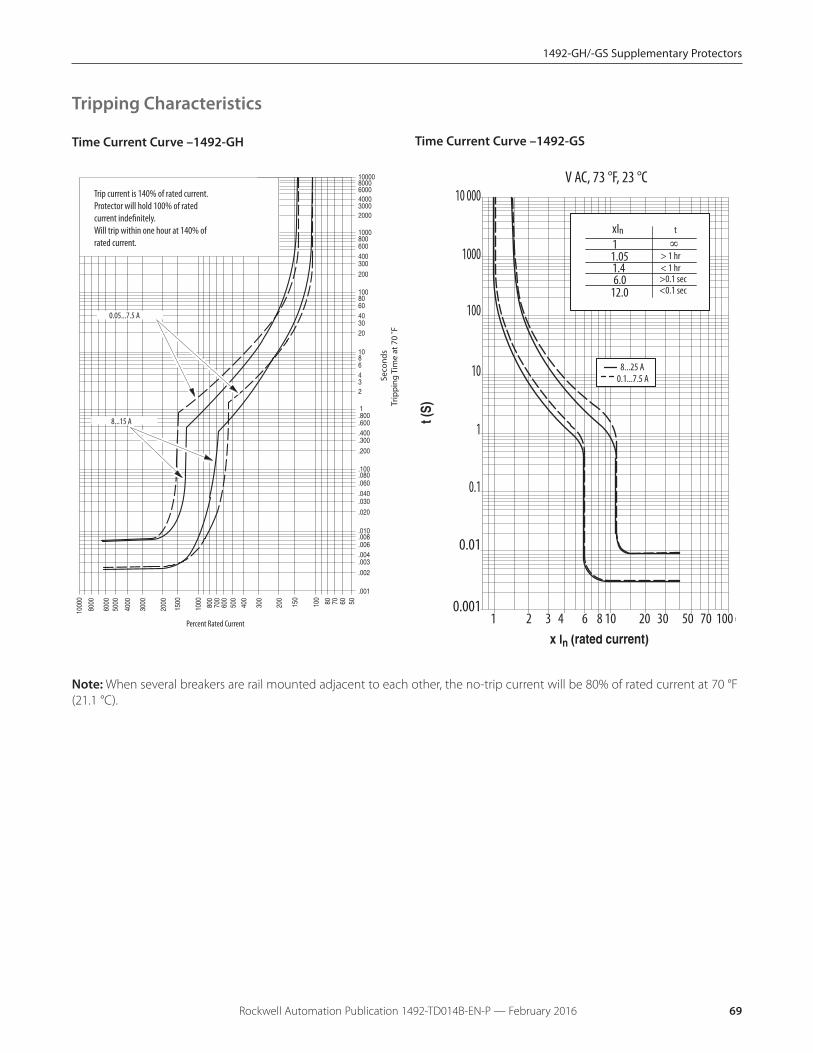
1492-GH/-GS Supplementary Protectors
Rockwell Automation Publication 1492-TD014B-EN-P — February 2016 69
Se
con
ds
Trip
pin
g T
ime
at
70
˚F
Trip current is 140% of rated current.Protector will hold 100% of ratedcurrent indefinitely.Will trip within one hour at 140% of rated current.
0.05...7.5 A
8...15 A
Percent Rated Current 1 2 3 4 6 8 10 20 30 50 70 100
1
0.001
0.01
0.1
10
100
1000
10 000V AC, 73 °F, 23 °C
11.051.46.0
12.0
xIn t
> 1 hr< 1 hr>0.1 sec<0.1 sec
8...25 A0.1...7.5 A
Note: When several breakers are rail mounted adjacent to each other, the no-trip current will be 80% of rated current at 70 °F(21.1 °C).
Time Current Curve –1492-GH Time Current Curve –1492-GS
Tripping Characteristics

1492-GH/-GS Supplementary Protectors
Rockwell Automation Publication 1492-TD014B-EN-P — February 201670
Notes
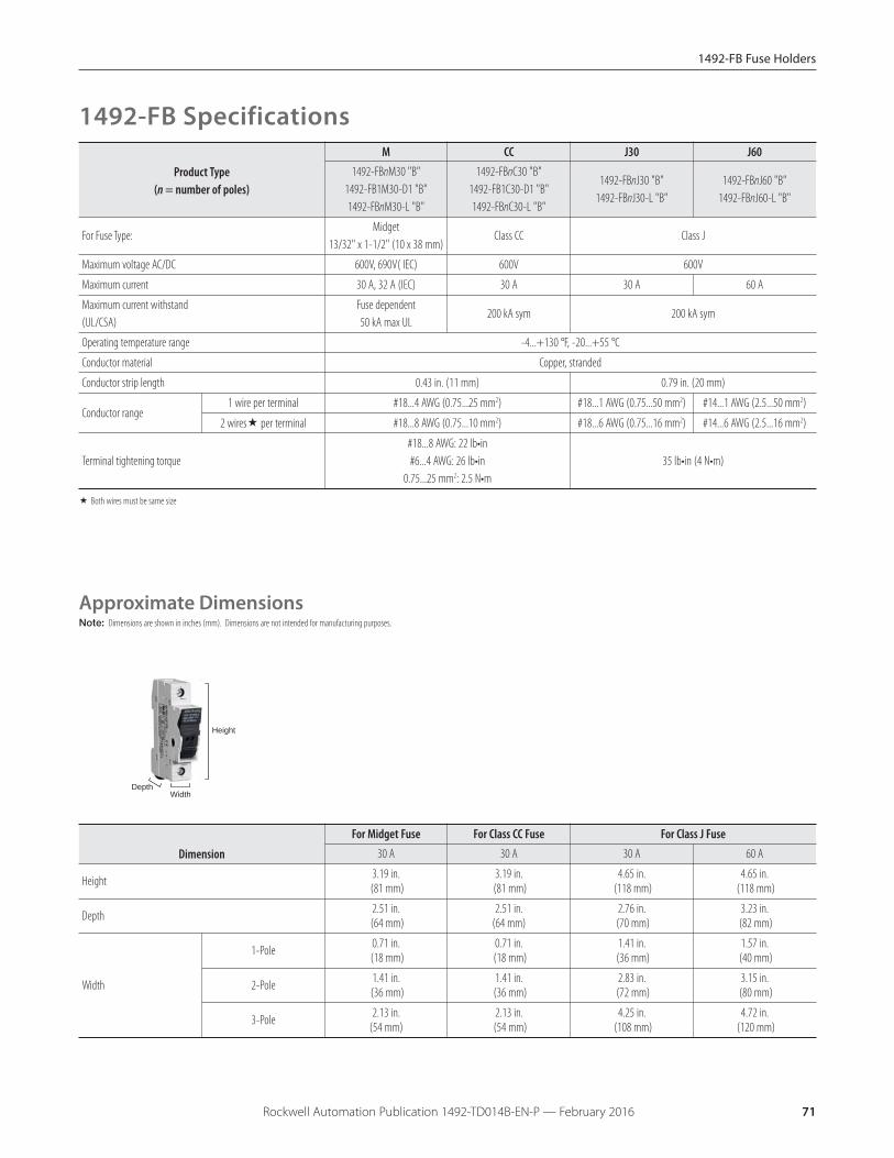
1492-FB Fuse Holders
Rockwell Automation Publication 1492-TD014B-EN-P — February 2016 71
Height
WidthDepth
Product Type(n = number of poles)
M CC J30 J601492-FBnM30 "B"
1492-FB1M30-D1 "B"1492-FBnM30-L "B"
1492-FBnC30 "B"1492-FB1C30-D1 "B"1492-FBnC30-L "B"
1492-FBnJ30 "B"1492-FBnJ30-L "B"
1492-FBnJ60 "B"1492-FBnJ60-L "B"
For Fuse Type:Midget
13/32" x 1-1/2" (10 x 38 mm)Class CC Class J
Maximum voltage AC/DC 600V, 690V( IEC) 600V 600V
Maximum current 30 A, 32 A (IEC) 30 A 30 A 60 A
Maximum current withstand(UL/CSA)
Fuse dependent50 kA max UL
200 kA sym 200 kA sym
Operating temperature range -4...+130 °F, -20...+55 °C
Conductor material Copper, stranded
Conductor strip length 0.43 in. (11 mm) 0.79 in. (20 mm)
Conductor range1 wire per terminal #18...4 AWG (0.75...25 mm2) #18...1 AWG (0.75...50 mm2) #14...1 AWG (2.5...50 mm2)
2 wires� per terminal #18...8 AWG (0.75...10 mm2) #18...6 AWG (0.75...16 mm2) #14...6 AWG (2.5...16 mm2)
Terminal tightening torque#18...8 AWG: 22 lb•in#6...4 AWG: 26 lb•in
0.75...25 mm2: 2.5 N•m35 lb•in (4 N•m)
� Both wires must be same size
Dimension
For Midget Fuse For Class CC Fuse For Class J Fuse30 A 30 A 30 A 60 A
Height 3.19 in.(81 mm)
3.19 in.(81 mm)
4.65 in.(118 mm)
4.65 in.(118 mm)
Depth 2.51 in.(64 mm)
2.51 in. (64 mm)
2.76 in.(70 mm)
3.23 in.(82 mm)
Width
1-Pole 0.71 in.(18 mm)
0.71 in.(18 mm)
1.41 in.(36 mm)
1.57 in.(40 mm)
2-Pole 1.41 in.(36 mm)
1.41 in.(36 mm)
2.83 in.(72 mm)
3.15 in.(80 mm)
3-Pole 2.13 in. (54 mm)
2.13 in.(54 mm)
4.25 in.(108 mm)
4.72 in.(120 mm)
Note: Dimensions are shown in inches (mm). Dimensions are not intended for manufacturing purposes.
1492-FB Specifications
Approximate Dimensions

Allen-Bradley, Rockwell Software, Rockwell Automation, and LISTEN. THINK. SOLVE are trademarks of Rockwell Automation, Inc.
Trademarks not belonging to Rockwell Automation are property of their respective companies.
Publication 1492-TD014B-EN-P - February 2016 Supersedes Publication 1492-TD014A-EN-P - August 2014 Copyright © 2016 Rockwell Automation, Inc. All rights reserved. Printed in the U.S.A.
Important User Information
Read this document and the documents listed in the additional resources section about installation, configuration, and operation of this equipment before you install, configure, operate, or maintain this product. Users are required to familiarize themselves with installation and wiring instructions in addition to requirements of all applicable codes, laws, and standards.
Activities including installation, adjustments, putting into service, use, assembly, disassembly, and maintenance are required to be carried out by suitably trained personnel in accordance with applicable code of practice.
If this equipment is used in a manner not specified by the manufacturer, the protection provided by the equipment may be impaired.
In no event will Rockwell Automation, Inc. be responsible or liable for indirect or consequential damages resulting from the use or application of this equipment.
The examples and diagrams in this manual are included solely for illustrative purposes. Because of the many variables and requirements associated with any particular installation, Rockwell Automation, Inc. cannot assume responsibility or liability for actual use based on the examples and diagrams.
No patent liability is assumed by Rockwell Automation, Inc. with respect to use of information, circuits, equipment, or software described in this manual.
Reproduction of the contents of this manual, in whole or in part, without written permission of Rockwell Automation, Inc., is prohibited.
Documentation Feedback
Your comments will help us serve your documentation needs better. If you have any suggestions on how to improve this document, complete this form, publication RA-DU002, available at http://www.rockwellautomation.com/literature/.
Rockwell Otomasyon Ticaret A.Ş., Kar Plaza İş Merkezi E Blok Kat:6 34752 İçerenköy, İstanbul, Tel: +90 (216) 5698400