Embed Size (px)
Citation preview
1
Mini-SARAn Imaging Radar on India’s Chandrayaan-1 Mission to the Moon
Paul D. SpudisMSR Principal Investigator
Lunar and Planetary InstituteHouston TX
www.spudislunarresources.com
NASA Program Management Challenge 2010February 2010
2
Origins
Waikaloa, Hawaii 2003Dr. Narendra Bhandari talk on proposed Chandrayaan-1
mission (not yet selected for flight)I approach him to fly radar; he encourages itAPL submits unsolicited letter proposalISRO decides on open competition for foreign payloads
(< 10 kg, < 100 W), Feb. 2004Submit formal proposal, April 2004Selected for flight, September 2004
3
Approval
Getting the money from NASATechnology interest from SOMD; exploration interest from ESMDTechnology development package developed and jointly funded
Getting approval from Dept. of StatePresent instrument concept/overview to DoS Dec. 2004Formal application for export license Jan. 2005State approval June 2005
Getting final approval from ISROTAA draft sent to ISRO in June 2005; no responseContinuous delay; demand for change of title of TAA documentTAA signed during May 2006 India visit by M. Griffin (NASA
Administrator)
4
Build and test
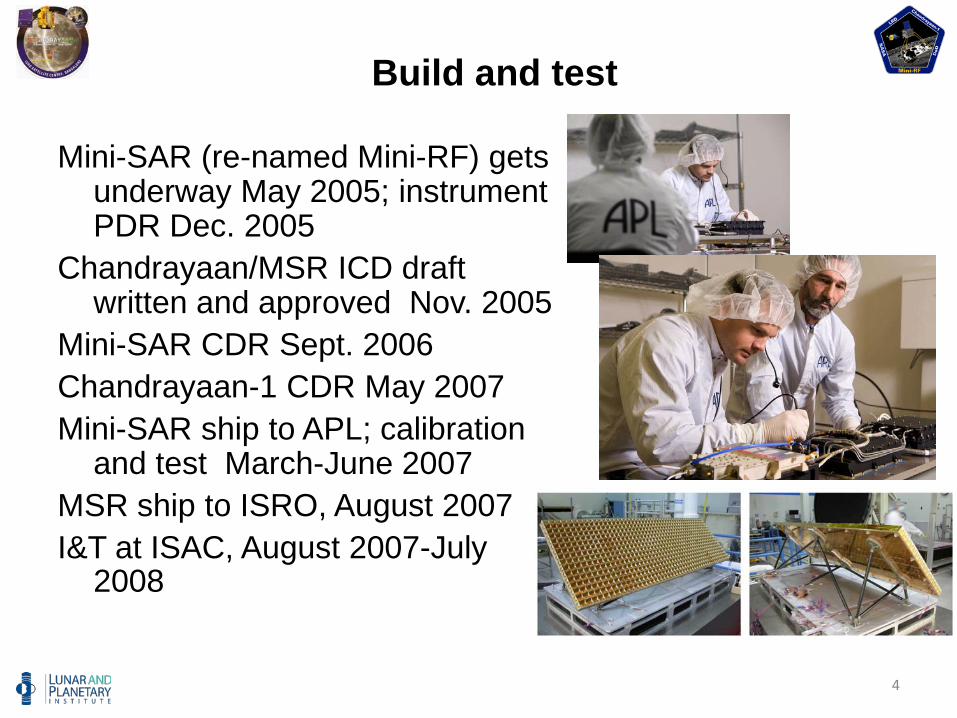
Mini-SAR (re-named Mini-RF) gets underway May 2005; instrument PDR Dec. 2005
Chandrayaan/MSR ICD draft written and approved Nov. 2005
Mini-SAR CDR Sept. 2006Chandrayaan-1 CDR May 2007Mini-SAR ship to APL; calibration
and test March-June 2007MSR ship to ISRO, August 2007I&T at ISAC, August 2007-July
2008
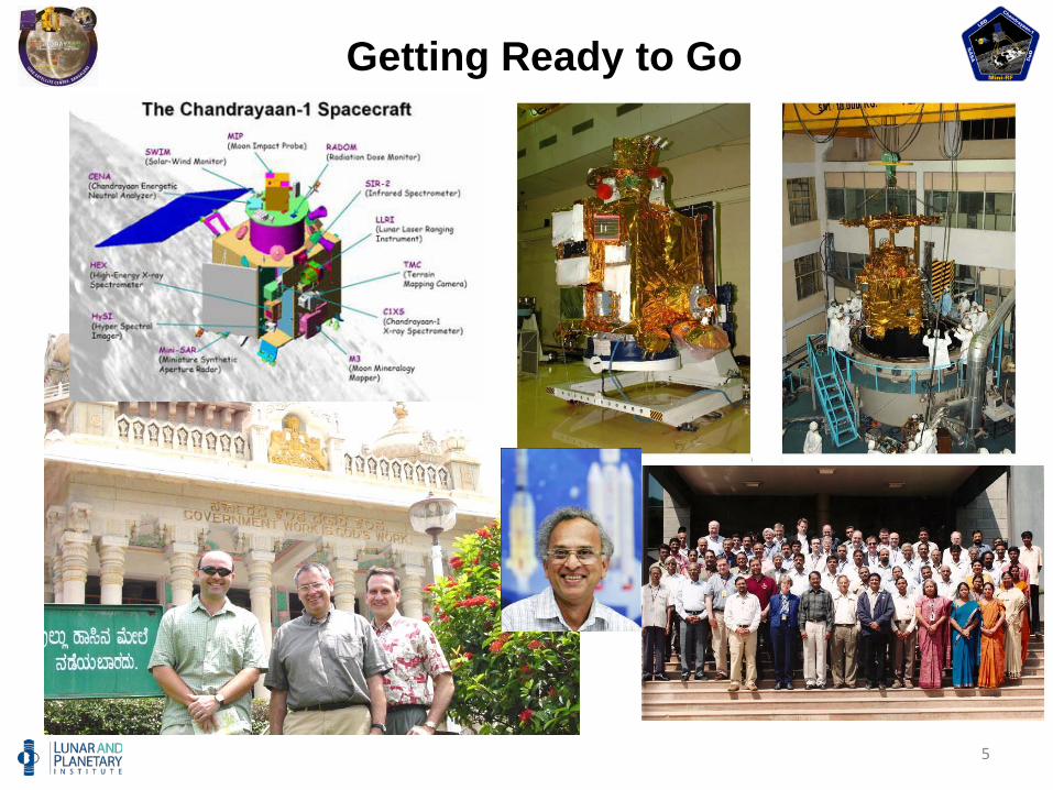
5
Getting Ready to Go
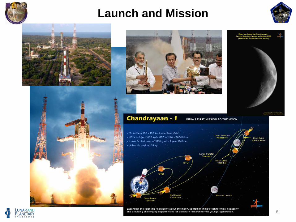
6
Launch and Mission
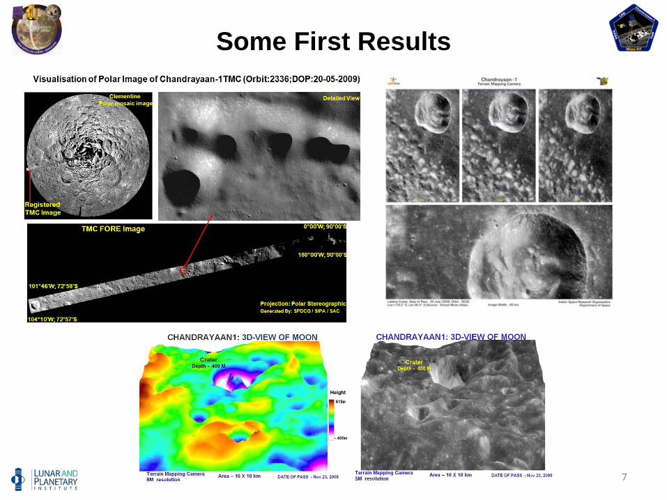
7
Some First Results
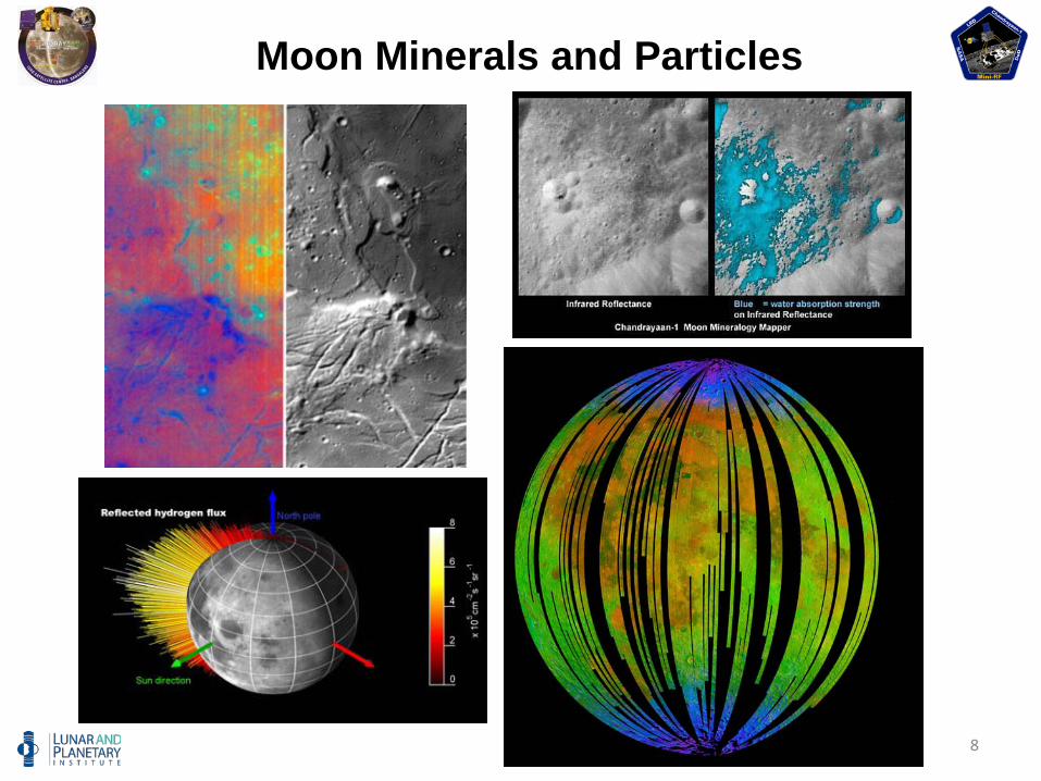
8
Moon Minerals and Particles
9
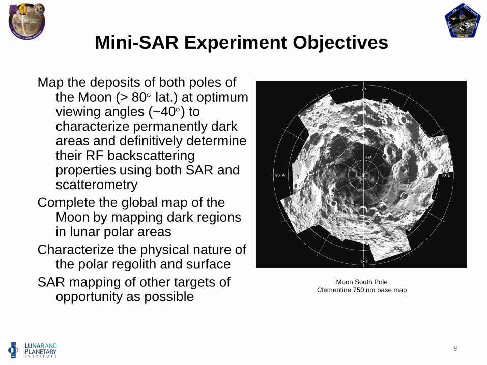
Mini-SAR Experiment Objectives
Map the deposits of both poles of the Moon (> 80° lat.) at optimum viewing angles (~40°) to characterize permanently dark areas and definitively determine their RF backscattering properties using both SAR and scatterometry
Complete the global map of the Moon by mapping dark regions in lunar polar areas
Characterize the physical nature of the polar regolith and surface
SAR mapping of other targets of opportunity as possible
Moon South PoleClementine 750 nm base map
10
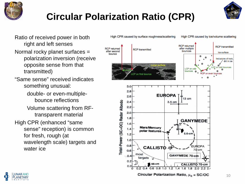
Circular Polarization Ratio (CPR)
Ratio of received power in both right and left senses
Normal rocky planet surfaces = polarization inversion (receive opposite sense from that transmitted)
“Same sense” received indicates something unusual:
double- or even-multiple-bounce reflections
Volume scattering from RF-transparent material
High CPR (enhanced “same sense” reception) is common for fresh, rough (at wavelength scale) targets and water ice
11
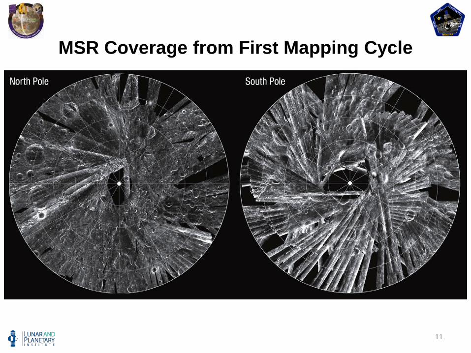
MSR Coverage from First Mapping Cycle
12
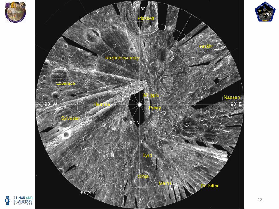
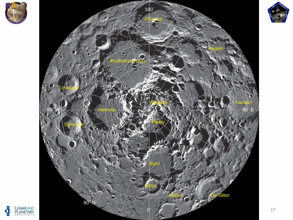
PearyHermite
Rozhdestvensky
Plaskett
Main L
80˚ N
Sylvester
Haskin
Byrd
NansenWhipple
De Sitter
Lovelace
Gloja
84˚ N
88˚ N
90˚ W
180˚
90˚ E
0˚
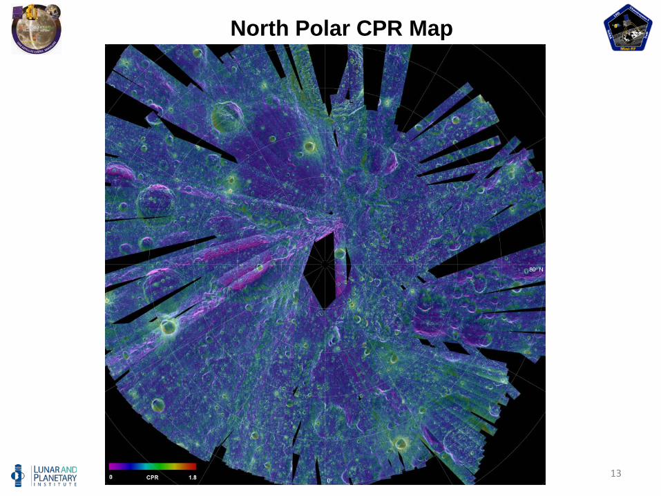
13
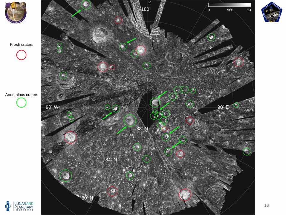
North Polar CPR Map
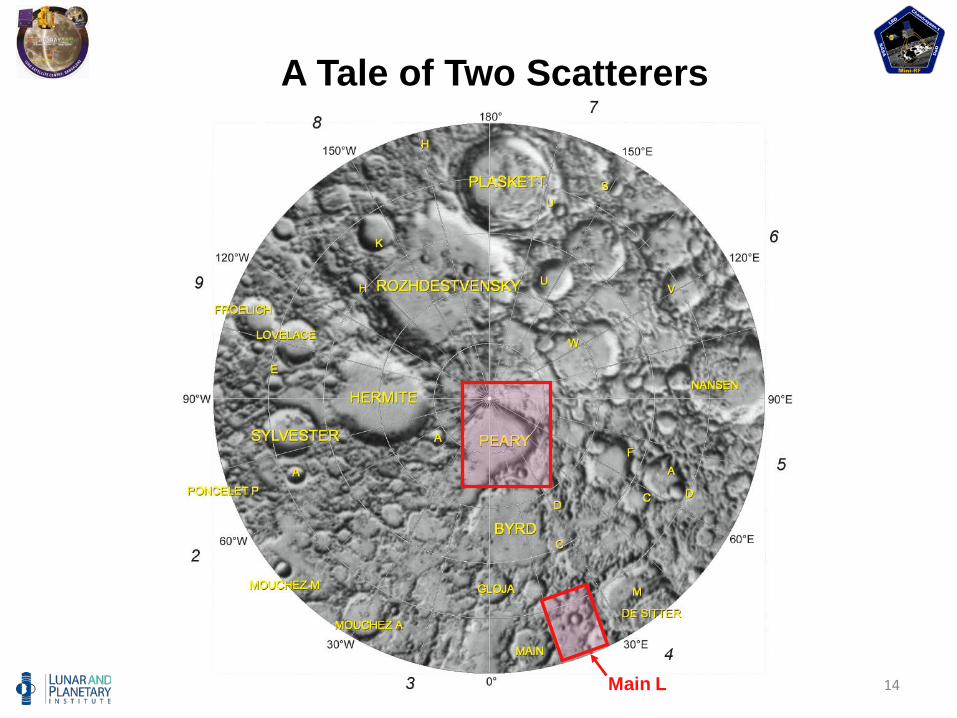
14
A Tale of Two Scatterers
Main L
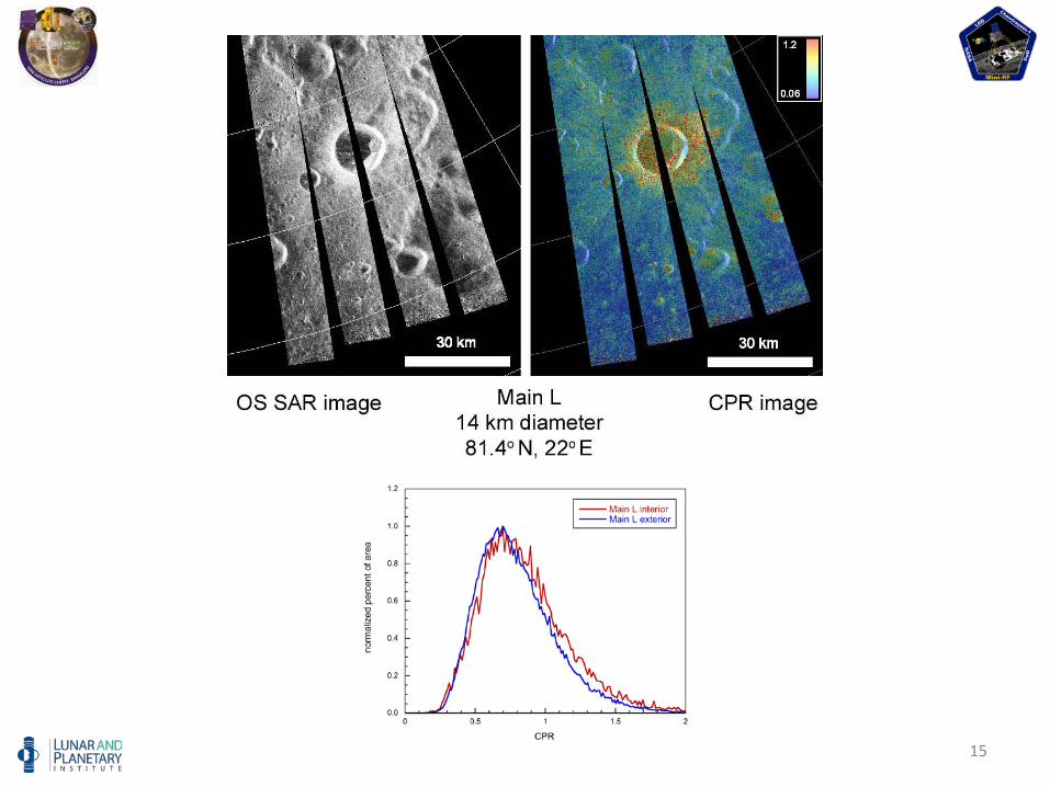
15
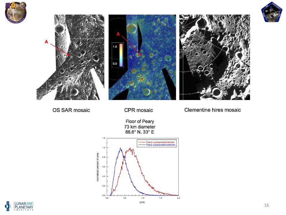
16
17
Peary
Hermite
Rozhdestvensky
Plaskett
Main L80˚ N
Sylvester
Haskin
Byrd
NansenWhipple
De Sitter
Lovelace
Gloja
84˚ N
88˚ N
90˚ W
180˚
90˚ E
0˚
18
Fresh craters
Anomalous craters
80˚ N
84˚ N
88˚ N
90˚ W
180˚
90˚ E
0˚
19
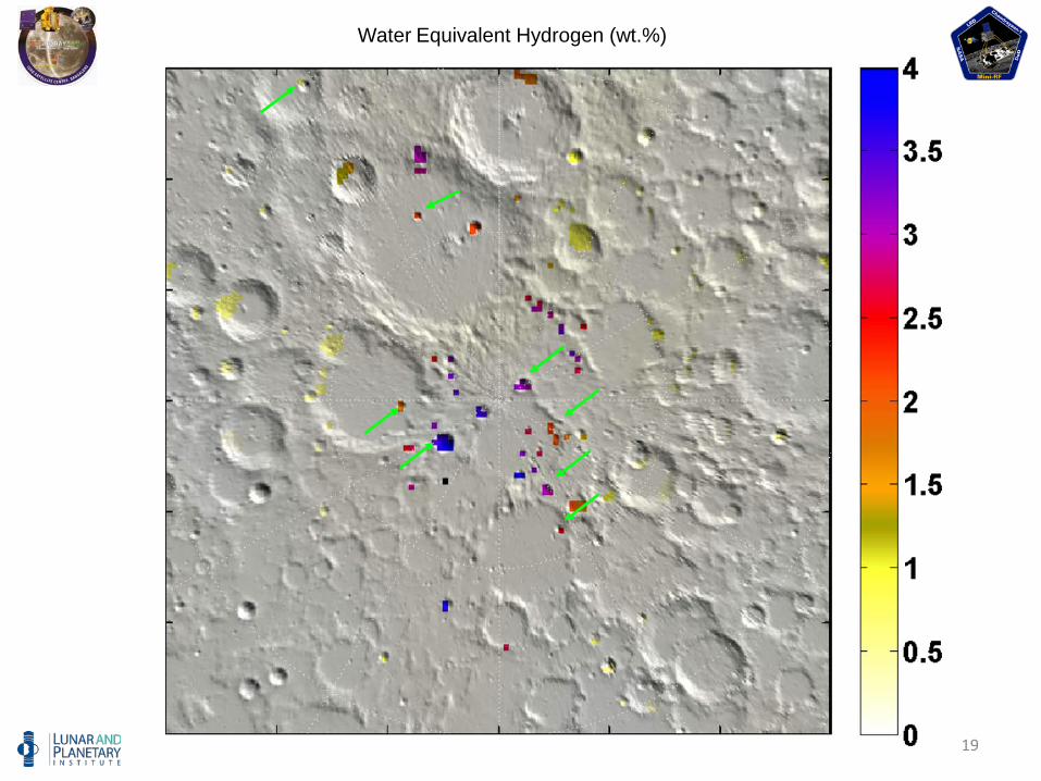
Water Equivalent Hydrogen (wt.%)
20
Summary
Mini-SAR successfully mapped about 90% of both polar areas; due to some operational issues, coverage is not contiguous
Calibration data from Earth and Moon have been acquired and partly processed; used to quantify radar response
Non-polar areas analyzed; results consistent with previous S-band radar mapping from Earth
Areas of high CPR have been identified:Some high CPR is clearly associated with surface roughness
(e.g., Main L ejecta blanket)Some deposits (e.g., near north pole on floor of Peary) show
high CPR and are restricted to the interior of craters; these features are in permanent darkness.
21
Some Lessons Learned
Sensitivities about ITARUS must recognize that foreign institutions may view
ITAR restrictions negatively
Foreign governments must realize that wording is not chosen by the flight partners
ITAR issues did not materially interfere with MSR build, test, and operation
ITAR compliance is simply an overhead lien that must be paid
22
Some Lessons Learned
Interactions with the pressOther governments may have different relationships
with press
Keep quiet and let your lead partner set the tone
“No comment” is a comment; it will not deter a determined reporter