Embed Size (px)
Citation preview
____________________________________________________________________________________________________________________
Address: Room 1701,Block A2, Longyuan Plaza, 549# Longkouxi Road, Guangzhou, China, 510640
Website: http://www.arm9.net Email: [email protected]
Tel: +86-20-85201025 Fax: +86-20-85261505
1 / 41
Mini6410 Hardware Spec
REVISION ORIGINATOR SCR REV DATE
0.1.0 FriendlyARM Co., Ltd March 28th, 2011
FriendlyARM Co., Ltd Confidential:
This document and information contained in it shall not be reproduced by, used by, or
disclosed to others except as expressly authorized in writing by FriendlyARM Co., Ltd.
FriendlyARM Co., Ltd
Guangzhou, China
copyright@2010
____________________________________________________________________________________________________________________
Address: Room 1701,Block A2, Longyuan Plaza, 549# Longkouxi Road, Guangzhou, China, 510640
Website: http://www.arm9.net Email: [email protected]
Tel: +86-20-85201025 Fax: +86-20-85261505
2 / 41
COPYRIGHT STATEMENT
The content (content being images, text, programs and scripts) of this English
manual is copyright © FriendlyARM Co., Ltd. All rights expressly reserved.
Any content of the manual printed or downloaded may not be sold, licensed,
transferred, copied or reproduced in whole or in part in any manner or in or on any
media to any person without the prior written consent of FriendlyARM Co., Ltd
including but not limited to:
transmission by any method
storage in any medium, system or program
display in any form
performance
hire, lease, rental or loan
Requests for permission to reproduce material from this manual should be addressed
to FriendlyARM Co., Ltd.
____________________________________________________________________________________________________________________
Address: Room 1701,Block A2, Longyuan Plaza, 549# Longkouxi Road, Guangzhou, China, 510640
Website: http://www.arm9.net Email: [email protected]
Tel: +86-20-85201025 Fax: +86-20-85261505
3 / 41
Index
1 Introduction to Mini6410 ....................................................................................................... 6
1.1 Mini6410 Overview ...................................................................................................... 8
1.2 Mini6410 Hardware Features ........................................................................................ 9
1.3 Board Dimension ......................................................................................................... 12
1.4 Linux Features ............................................................................................................. 13
1.5 WinCE 6.0 Features ..................................................................................................... 16
1.6 Android Features ......................................................................................................... 18
1.7 Ubuntu Features .......................................................................................................... 20
2. Board Schematic .................................................................................................................. 21
2.1 Jumper ......................................................................................................................... 21
2.2 Schematic .................................................................................................................... 21
3 Interface Specifications ........................................................................................................ 23
3.1 Address Space.............................................................................................................. 23
3.2 Power ........................................................................................................................... 23
3.3 Serial Port .................................................................................................................... 24
3.4 USB Interface .............................................................................................................. 25
3.5 Network Interface ........................................................................................................ 26
3.6 Audio Interface ............................................................................................................ 27
3.7 TV Output .................................................................................................................... 27
____________________________________________________________________________________________________________________
Address: Room 1701,Block A2, Longyuan Plaza, 549# Longkouxi Road, Guangzhou, China, 510640
Website: http://www.arm9.net Email: [email protected]
Tel: +86-20-85201025 Fax: +86-20-85261505
4 / 41
3.8 JTAG Interface ............................................................................................................ 28
3.9 LED ............................................................................................................................. 29
3.10 User Key .................................................................................................................... 30
3.11 Double LCD Interface ............................................................................................... 31
3.12 ADC Input ................................................................................................................. 32
3.13 PWM Buzzer ............................................................................................................. 33
3.14 Infrared Receiver ....................................................................................................... 34
3.15 I2C-EEPROM ........................................................................................................... 34
3.16 SD Card ..................................................................................................................... 35
3.17 SDIO-II//SD-WiFi ..................................................................................................... 36
3.18 CMOS Camera Interface ........................................................................................... 37
3.19 GPIO .......................................................................................................................... 39
3.20 System Bus ................................................................................................................ 40
____________________________________________________________________________________________________________________
Address: Room 1701,Block A2, Longyuan Plaza, 549# Longkouxi Road, Guangzhou, China, 510640
Website: http://www.arm9.net Email: [email protected]
Tel: +86-20-85201025 Fax: +86-20-85261505
5 / 41
This manual is intended to provide the user with an overview of the Mini6410
board, its benefits, features, specifications, and set up procedures.
____________________________________________________________________________________________________________________
Address: Room 1701,Block A2, Longyuan Plaza, 549# Longkouxi Road, Guangzhou, China, 510640
Website: http://www.arm9.net Email: [email protected]
Tel: +86-20-85201025 Fax: +86-20-85261505
6 / 41
1 Introduction to Mini6410
The Mini6410 development board is an excellent ARM11 board offering a comprehensive
solution integrating both hardware and software. It is designed, developed and distributed by
FriendlyARM in Guangzhou, China. It applies the Samsung S3C6410 microprocessor and
inherits all the features and benefits of our most popular Mini2440 products excelling in
quality and easy to use with low cost. Compared to our previous products it has more reliable
design and varied interfaces. These features make it easily and widely used in MID
development, auto electronic devices, industrial applications, GPS systems and multimedia
systems. It is good for educational training, embedded development and DIY as well.
In general the Mini6410 board has the following interfaces:
double LCD interfaces,
1* 4-wire resistor touch screen interface,
1 * 100M Ethernet interface,
1 * DB9 5-wire serial port
1 * Mini USB 2.0-OTG interface
1 * USB Host 1.1 interface,
1 * 3.5mm audio output
1 * on board microphone interface,
1 * TV-OUT
____________________________________________________________________________________________________________________
Address: Room 1701,Block A2, Longyuan Plaza, 549# Longkouxi Road, Guangzhou, China, 510640
Website: http://www.arm9.net Email: [email protected]
Tel: +86-20-85201025 Fax: +86-20-85261505
7 / 41
1 * SD card socket,
1 * Infrared receiver,
4 * TTL serial port,
1 * CMOS camera interface,
1 * 40pin bus interface,
1 * 30pin GPIO interface (it can be multiplexed to SPI, I2C and interrupts. It includes 3
ADC and 1 DAC.),
1 * SDIO2 interface (can be connected to SD WiFi module),
1 * 10pin JTAG interface,
1 * PWM buzzer,
1 * I2C-EEPROM,
1 * backup battery for RTC,
1 * AD adjustable resistor,
8 * User button,
4 * LED
All these benefits, combined with our dedicated 4.3-inch LCD, bring you wonderful
experience: all in your hand!
In addition we make the best use of the SD booting feature, by using our specially
developed Superboot, enabling the board bootable from an SD card. With Superboot users
can copy various systems (WindowsCE6/Linux/Android/Ubuntu/uCos2) into an SD card (up
____________________________________________________________________________________________________________________
Address: Room 1701,Block A2, Longyuan Plaza, 549# Longkouxi Road, Guangzhou, China, 510640
Website: http://www.arm9.net Email: [email protected]
Tel: +86-20-85201025 Fax: +86-20-85261505
8 / 41
to a maximum memory of 32G) and install them on the board without connecting to a PC, or
run them on the SD card without burning systems onto the board. In one word, this
one-minute booting process is “Revolutionary to System Installation and Running”.
Customers can get the latest information and news about our products by visiting:
http://www.arm9.net
1.1 Mini6410 Overview
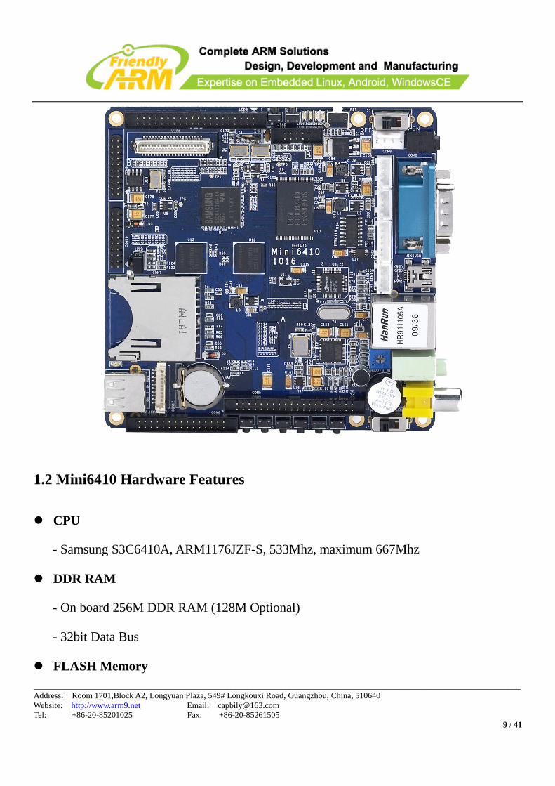
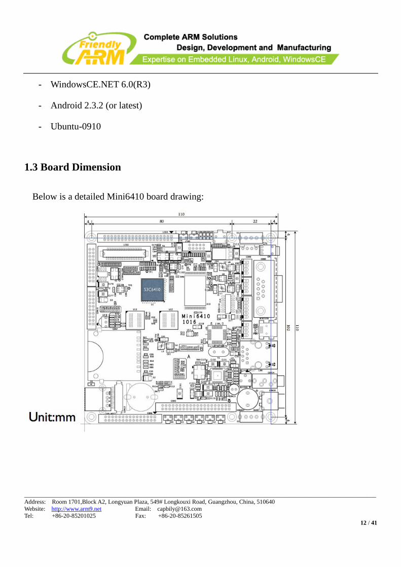
The Mini6410 development board is a 110 x 110(mm) board equipped with a wide variety
of connectors, interfaces and ports. Here’s the layout:
____________________________________________________________________________________________________________________
Address: Room 1701,Block A2, Longyuan Plaza, 549# Longkouxi Road, Guangzhou, China, 510640
Website: http://www.arm9.net Email: [email protected]
Tel: +86-20-85201025 Fax: +86-20-85261505
9 / 41
1.2 Mini6410 Hardware Features
CPU
- Samsung S3C6410A, ARM1176JZF-S, 533Mhz, maximum 667Mhz
DDR RAM
- On board 256M DDR RAM (128M Optional)
- 32bit Data Bus
FLASH Memory
____________________________________________________________________________________________________________________
Address: Room 1701,Block A2, Longyuan Plaza, 549# Longkouxi Road, Guangzhou, China, 510640
Website: http://www.arm9.net Email: [email protected]
Tel: +86-20-85201025 Fax: +86-20-85261505
10 / 41
- On board 128M/256M/1GB SLC Nand Flash or 2GB MLC Nand Flash
LCD
- Four-wire touch screen interface
- Support black and white, 4 level grayscale, 16 level grayscale, 256-color、4096-color
STN LCD, 3.5-inch to 12.1-inch, screen resolution 1024x768;
- Support black and white, 4 level grayscale, 16 level grayscale, 256-color, 64K-color,
true color TFT LCD, 3.5-inch to 12.1-inch, screen resolution 1024x768,
Interfaces and External Accessories
- 1 * 100M Ethernet RJ-45 port (powered by the DM9000 network chip)
- 1 * DB9 RS232 five-wire serial port (with 4 TTL serial ports)
- 1 * mini USB Slave 2.0 with OTG
- 3.5mm dual stereo audio output and single microphone input
- 1 * TV-OUT output with RCA port
- 1 * USB Host 1.1 port
- 1 * standard SD card socket
- 1 * Infrared receiver
- 5V power supply
- 1 * I2C-EEPROM chip (256 byte), for I2C Bus test
- 4 * USER LED (green)
- 8 * USER Button (interrupt pins, extended from board)
____________________________________________________________________________________________________________________
Address: Room 1701,Block A2, Longyuan Plaza, 549# Longkouxi Road, Guangzhou, China, 510640
Website: http://www.arm9.net Email: [email protected]
Tel: +86-20-85201025 Fax: +86-20-85261505
11 / 41
- 1 * Adjustable resistor, for AD conversion testing
- 1 * PWM buzzer
- Onboard real-time clock backup battery
Extended Interfaces
- 4 * Serial port socket (TTL, 2.0mm spaced socket)
- 1 * 10 pin 2.0mm spaced JTAG interface
- Double LCD Interfaces (one 41 pin connector compatible with Mini2440 LCD and the
other 40 pin 2.0 mm spaced doubled line connector)
- 1 * 20pin 2.0mm spaced SDIO interface (can be connected to SD WiFi and include an
SPI and an I2C)
- 1 * 20pin 2.0mm spaced CMOS camera interface
- 1 * 30 pin 2.0mm spaced GPIO port
- 1 * 40 pin 2.0mm spaced system bus interface
- 1 * 10pin 2.0mm spaced button socket including 8 interrupt pins, power and ground
PCB Overview
- PCB layer: 6
- 110 x 110 mm
OS Support
The Mini6410 development board currently can load the following operating systems:
- Linux2.6.38(or latest) + Qtopia-2.2.0 + QtE-4.7.0
____________________________________________________________________________________________________________________
Address: Room 1701,Block A2, Longyuan Plaza, 549# Longkouxi Road, Guangzhou, China, 510640
Website: http://www.arm9.net Email: [email protected]
Tel: +86-20-85201025 Fax: +86-20-85261505
12 / 41
- WindowsCE.NET 6.0(R3)
- Android 2.3.2 (or latest)
- Ubuntu-0910
1.3 Board Dimension
Below is a detailed Mini6410 board drawing:
____________________________________________________________________________________________________________________
Address: Room 1701,Block A2, Longyuan Plaza, 549# Longkouxi Road, Guangzhou, China, 510640
Website: http://www.arm9.net Email: [email protected]
Tel: +86-20-85201025 Fax: +86-20-85261505
13 / 41
1.4 Linux Features
Kernel Version
- Linux 2.6.38(or latest)
Boot Loader
- U-boot-1.6.1: open source, can be configured as Nand booting or SD booting
- Superboot: developed by FriendlyARM, not open sourced
File Systems
- YAFFS2: recommended
- UBIFS: recommended for MLC nand Flash
- CRAMFS
- EXT2/3
- FAT32
- NFS
Drivers (all open source)
- Driver for 4 serial ports
- DM9000 driver
- Audio driver (WM9714)
- RTC driver
- Drivers for 4 User LEDs
____________________________________________________________________________________________________________________
Address: Room 1701,Block A2, Longyuan Plaza, 549# Longkouxi Road, Guangzhou, China, 510640
Website: http://www.arm9.net Email: [email protected]
Tel: +86-20-85201025 Fax: +86-20-85261505
14 / 41
- USB host driver
- LCD driver (it supports 3.5-inch, 4.3-inch, 7-inch, 8-inch, LCD2VGA1024x768,
LCD2VGA800x600, LCD2VGA640x480 and EZVGA800x600)
- 4-wire touch screen driver and 1-wire precise touch driver
- USB camera driver
- Drivers for USB mouse, keyboard, flash drive and portable hard disk
- SD card driver, up to 32 GB
- I2C driver
- ADC driver
- LCD backlight driver
- Watchdog driver (watchdog reset is cold reset)
- Multimedia drivers(including JPEG, FIMC, MFC, 2D/3D Accelerator, TVENC and
TVSCALER)
- CMOS camera driver
- Back light adjustor. This allows users to adjust the board’s backlight up to 127 levels
and experience a gradually dim effect when turning it down.
- SPI driver
Basic Applications and Utilities
- Busybox1.17 (Linux tool kit including basic Linux commands)
- Telnet, FTP and inetd (remote login tool)
____________________________________________________________________________________________________________________
Address: Room 1701,Block A2, Longyuan Plaza, 549# Longkouxi Road, Guangzhou, China, 510640
Website: http://www.arm9.net Email: [email protected]
Tel: +86-20-85201025 Fax: +86-20-85261505
15 / 41
- boa (web server)
- Madplay (command line mp3 player)
- Snapshot (command line screenshot tool)
- ifconfig, ping, route and so on (basic network commands)
Graphic User Interface
- Qtopia-2.2.0: open source, including two versions: one for x86 and the other for ARM
- QtE-4.7.0: open source, only for ARM
- Qt-extended -4.4.3: open source, Qtopia for handset, alternatively named Qtopia4
Qtopia Applications and Utilities (Note: the following GUI applications are
developed by FriendlyARM, which are not open sourced)
- A/D conversion test utility
- LED test utility
- User button test utility
- I2C-EEPROM read/write test utility
- LCD test utility
- Ping test utility
- USB camera preview and picture taking
- Audio recorder
- Web browser(konquor, open sourced)
- Watchdog test utility
____________________________________________________________________________________________________________________
Address: Room 1701,Block A2, Longyuan Plaza, 549# Longkouxi Road, Guangzhou, China, 510640
Website: http://www.arm9.net Email: [email protected]
Tel: +86-20-85201025 Fax: +86-20-85261505
16 / 41
- Network configuration utility
- Backlight control utility
- Language setting utility (English, Chinese and Japanese)
- Penpad utility (for touch pen testing)
- MMC/SD card and flash drive utility enabling auto mounting and unmounting
- Qt4 switcher
- Qtopia4 switcher
- SMPLAYER
- arm-none-linux -4.5.1-v6-vfp: cross compiler
1.5 WinCE 6.0 Features
Version
- Windows CE Embedded 6.0 R3
Features
- Fast booting (boot up within 15 seconds)
- Support bootlogo download via USB, or SD Card only.
- Configurable NBOOT header files: Users can customize the process bar’s color,
position, length and width, and startup image’s position and background.
- CMOS camera driver
- LED driver
____________________________________________________________________________________________________________________
Address: Room 1701,Block A2, Longyuan Plaza, 549# Longkouxi Road, Guangzhou, China, 510640
Website: http://www.arm9.net Email: [email protected]
Tel: +86-20-85201025 Fax: +86-20-85261505
17 / 41
- Driver for 8 user buttons
- PWM buzzer driver
- LCD driver (it supports 3.5-inch, 4.3-inch, 7-inch, 8-inch, LCD2VGA1024x768,
LCD2VGA800x600, LCD2VGA640x480 and EZVGA800x600)
- RTC driver
- DM9000 driver
- Large memory high speed SD/SDHC card driver(up to 32GB)
- Touch screen driver
- Audio input/output driver (WM9714 chip)
- Drivers for USB keyboard, mouse, flash drive
- Drivers for serial ports COM2, 3 and 4
- Multimedia driver (including JPEG, FIMC, 2D/3D Accelerator, MFC, TVENC and
TVSCALER)
- USB WiFi plug and play(only for RT2070/RT3070 based card)
- USB Bluetooth plug and play
- 1-wire precise touch screen driver. It supports 4.3-inch to 21-inch touch screen
- Back light adjustor. This allows users to adjust the board’s backlight up to 127 levels
and experience a gradually dim effect when turning it down.
Utility Highlights
- Super media player: TCPMP,it supports decoding and H.264/263, MPEG4 video files
____________________________________________________________________________________________________________________
Address: Room 1701,Block A2, Longyuan Plaza, 549# Longkouxi Road, Guangzhou, China, 510640
Website: http://www.arm9.net Email: [email protected]
Tel: +86-20-85201025 Fax: +86-20-85261505
18 / 41
- Serial port assistant
- User button test utility
- LED test utility
- PWM buzzer test utility
- Audio recorder
- OpenGL utility
- Autorun setup utility: to set up applications to be run at startup
- Painter: for touch screen test
- Notepad
1.6 Android Features
Linux Kernel
- Linux-2.6.36
Boot Loader
- U-boot-1.6
File Systems
- FAT32
- YAFFS2
- UBIFS(recommended)
____________________________________________________________________________________________________________________
Address: Room 1701,Block A2, Longyuan Plaza, 549# Longkouxi Road, Guangzhou, China, 510640
Website: http://www.arm9.net Email: [email protected]
Tel: +86-20-85201025 Fax: +86-20-85261505
19 / 41
- EXT2/3
Android Version and Features
- Android 2.3
- Support SD WiFi, USB WiFi
- Support GPS
- Support CMOS camera
- Support USB 3G Card: more than one hundred kinds of USB 3G cards which cover
all three systems: WCDMA, CDMA2000 and TD-SCDMA etc.
- Flash drive plug and play: up to a maximum memory of 32G
- USB Bluetooth plug and play
- Support accurate touch
- Support screen rotation
- Back light adjustor. This allows users to adjust the board’s backlight up to 127 levels
and experience a gradually dim effect when turning it down
- GUI utility for Ethernet configuration, enabling both auto and manual IP setup
- Support USB ADB debug and download
- Support simplified Chinese, traditional Chinese, English and Japanese
- Optimized web browser featuring fast internet surfing
____________________________________________________________________________________________________________________
Address: Room 1701,Block A2, Longyuan Plaza, 549# Longkouxi Road, Guangzhou, China, 510640
Website: http://www.arm9.net Email: [email protected]
Tel: +86-20-85201025 Fax: +86-20-85261505
20 / 41
1.7 Ubuntu Features
Linux Kernel
- Linux-2.6.38
Boot Loader
- Superboot: boot from SD card and load the kernel and file system
File Systems
- FAT32
- UBIFS
- EXT2/3
____________________________________________________________________________________________________________________
Address: Room 1701,Block A2, Longyuan Plaza, 549# Longkouxi Road, Guangzhou, China, 510640
Website: http://www.arm9.net Email: [email protected]
Tel: +86-20-85201025 Fax: +86-20-85261505
21 / 41
2. Board Schematic
2.1 Jumper
There are no jumpers on this board. This design makes the board easy for users.
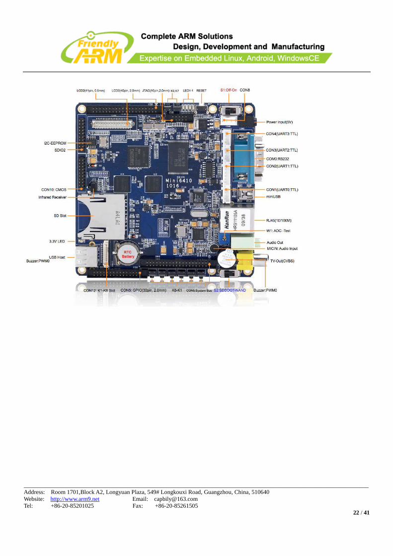
2.2 Schematic
The Mini6410 schematic is presented as below. It includes most of the popular interfaces,
ports, IOs and buses on a 110 x 110 mm board.
Note: in the diagram below those orange points indicate the first pins of those
interfaces/ports/connectors accordingly.
____________________________________________________________________________________________________________________
Address: Room 1701,Block A2, Longyuan Plaza, 549# Longkouxi Road, Guangzhou, China, 510640
Website: http://www.arm9.net Email: [email protected]
Tel: +86-20-85201025 Fax: +86-20-85261505
22 / 41
____________________________________________________________________________________________________________________
Address: Room 1701,Block A2, Longyuan Plaza, 549# Longkouxi Road, Guangzhou, China, 510640
Website: http://www.arm9.net Email: [email protected]
Tel: +86-20-85201025 Fax: +86-20-85261505
23 / 41
3 Interface Specifications
This section describes in detail each interface/port on the board. For more details users can
refer to the complete schematics (in PDF and Protel99SE) in the CDs shipped together with
this product.
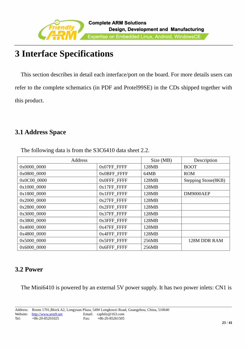
3.1 Address Space
The following data is from the S3C6410 data sheet 2.2.
Address Size (MB) Description
0x0000_0000 0x07FF_FFFF 128MB BOOT
0x0800_0000 0x0BFF_FFFF 64MB ROM
0x0C00_0000 0x0FFF_FFFF 128MB Stepping Stone(8KB)
0x1000_0000 0x17FF_FFFF 128MB
0x1800_0000 0x1FFF_FFFF 128MB DM9000AEP
0x2000_0000 0x27FF_FFFF 128MB
0x2800_0000 0x2FFF_FFFF 128MB
0x3000_0000 0x37FF_FFFF 128MB
0x3800_0000 0x3FFF_FFFF 128MB
0x4000_0000 0x47FF_FFFF 128MB
0x4800_0000 0x4FFF_FFFF 128MB
0x5000_0000 0x5FFF_FFFF 256MB 128M DDR RAM
0x6000_0000 0x6FFF_FFFF 256MB
3.2 Power
The Mini6410 is powered by an external 5V power supply. It has two power inlets: CN1 is
____________________________________________________________________________________________________________________
Address: Room 1701,Block A2, Longyuan Plaza, 549# Longkouxi Road, Guangzhou, China, 510640
Website: http://www.arm9.net Email: [email protected]
Tel: +86-20-85201025 Fax: +86-20-85261505
24 / 41
for 5V power adapter and the white CON8 is a 4 pin socket used to connect an external
power supply when the board is embedded in a closed box. The voltage is 5V and current is
800mA.
CON8 PIN Spec
1 VDD5V
2 GND
3 GND
4 VDDIN
Note: when connected to an extended cable, the S1 switch works too.
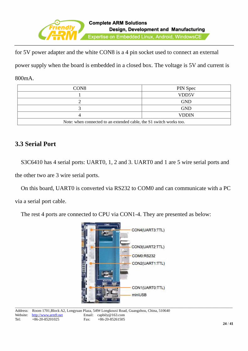
3.3 Serial Port
S3C6410 has 4 serial ports: UART0, 1, 2 and 3. UART0 and 1 are 5 wire serial ports and
the other two are 3 wire serial ports.
On this board, UART0 is converted via RS232 to COM0 and can communicate with a PC
via a serial port cable.
The rest 4 ports are connected to CPU via CON1-4. They are presented as below:
____________________________________________________________________________________________________________________
Address: Room 1701,Block A2, Longyuan Plaza, 549# Longkouxi Road, Guangzhou, China, 510640
Website: http://www.arm9.net Email: [email protected]
Tel: +86-20-85201025 Fax: +86-20-85261505
25 / 41
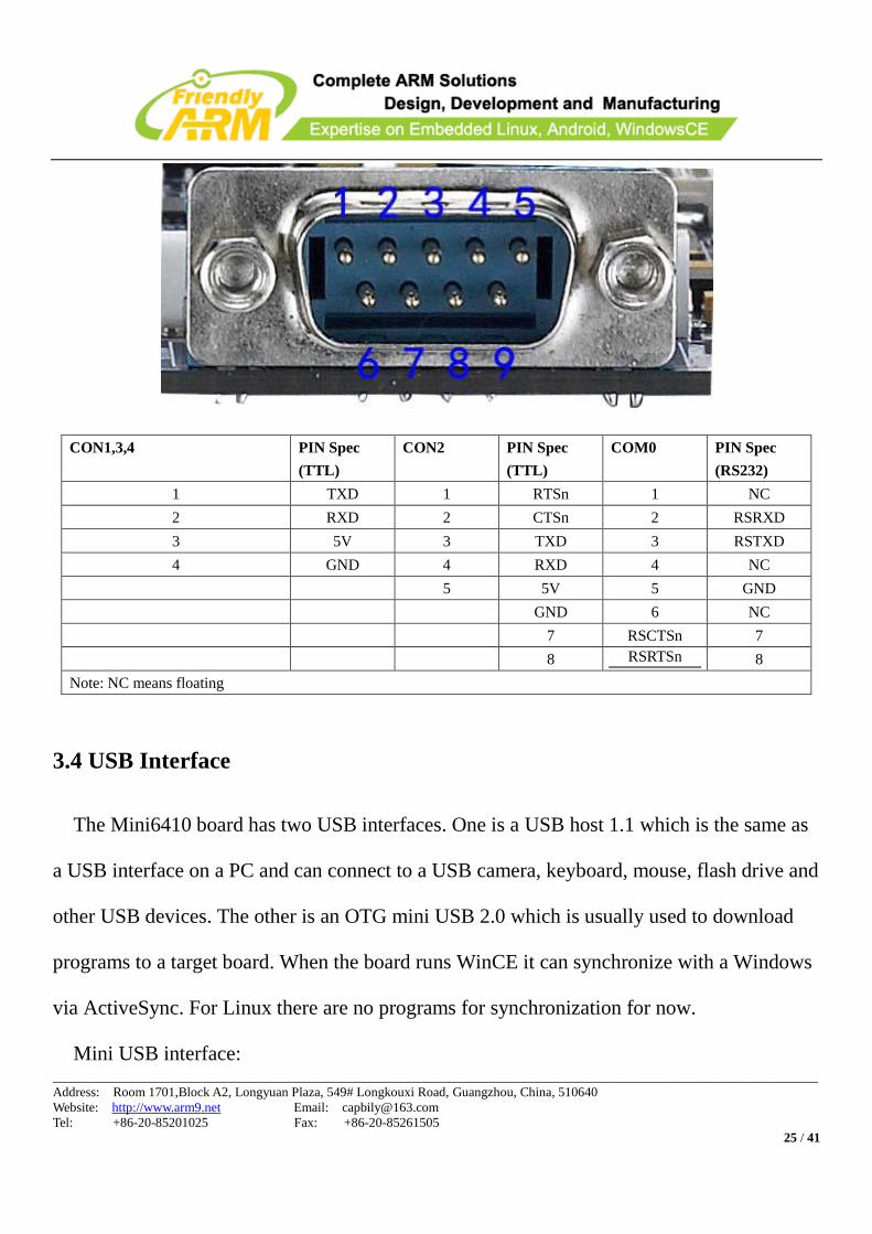
CON1,3,4 PIN Spec
(TTL)
CON2 PIN Spec
(TTL)
COM0 PIN Spec
(RS232)
1 TXD 1 RTSn 1 NC
2 RXD 2 CTSn 2 RSRXD
3 5V 3 TXD 3 RSTXD
4 GND 4 RXD 4 NC
5 5V 5 GND
GND 6 NC
7 RSCTSn 7
8 RSRTSn 8
Note: NC means floating
3.4 USB Interface
The Mini6410 board has two USB interfaces. One is a USB host 1.1 which is the same as
a USB interface on a PC and can connect to a USB camera, keyboard, mouse, flash drive and
other USB devices. The other is an OTG mini USB 2.0 which is usually used to download
programs to a target board. When the board runs WinCE it can synchronize with a Windows
via ActiveSync. For Linux there are no programs for synchronization for now.
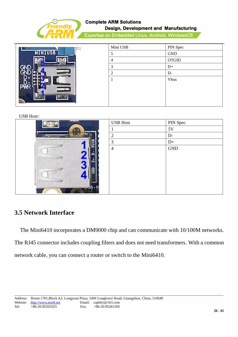
Mini USB interface:
____________________________________________________________________________________________________________________
Address: Room 1701,Block A2, Longyuan Plaza, 549# Longkouxi Road, Guangzhou, China, 510640
Website: http://www.arm9.net Email: [email protected]
Tel: +86-20-85201025 Fax: +86-20-85261505
26 / 41
Mini USB PIN Spec
5 GND
4 OTGID
3 D+
2 D-
1 Vbus
USB Host:
USB Host PIN Spec
1 5V
2 D-
3 D+
4 GND
3.5 Network Interface
The Mini6410 incorporates a DM9000 chip and can communicate with 10/100M networks.
The RJ45 connector includes coupling filters and does not need transformers. With a common
network cable, you can connect a router or switch to the Mini6410.
____________________________________________________________________________________________________________________
Address: Room 1701,Block A2, Longyuan Plaza, 549# Longkouxi Road, Guangzhou, China, 510640
Website: http://www.arm9.net Email: [email protected]
Tel: +86-20-85201025 Fax: +86-20-85261505
27 / 41
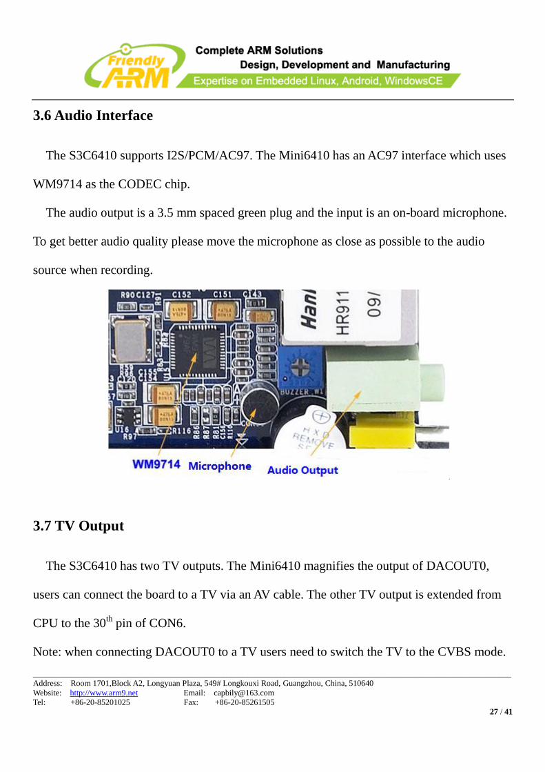
3.6 Audio Interface
The S3C6410 supports I2S/PCM/AC97. The Mini6410 has an AC97 interface which uses
WM9714 as the CODEC chip.
The audio output is a 3.5 mm spaced green plug and the input is an on-board microphone.
To get better audio quality please move the microphone as close as possible to the audio
source when recording.
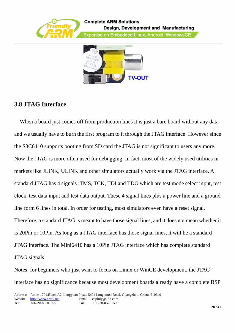
3.7 TV Output
The S3C6410 has two TV outputs. The Mini6410 magnifies the output of DACOUT0,
users can connect the board to a TV via an AV cable. The other TV output is extended from
CPU to the 30th
pin of CON6.
Note: when connecting DACOUT0 to a TV users need to switch the TV to the CVBS mode.
____________________________________________________________________________________________________________________
Address: Room 1701,Block A2, Longyuan Plaza, 549# Longkouxi Road, Guangzhou, China, 510640
Website: http://www.arm9.net Email: [email protected]
Tel: +86-20-85201025 Fax: +86-20-85261505
28 / 41
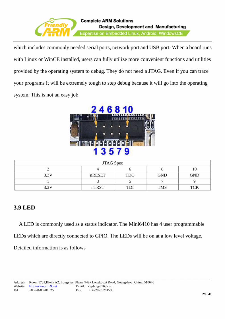
3.8 JTAG Interface
When a board just comes off from production lines it is just a bare board without any data
and we usually have to burn the first program to it through the JTAG interface. However since
the S3C6410 supports booting from SD card the JTAG is not significant to users any more.
Now the JTAG is more often used for debugging. In fact, most of the widely used utilities in
markets like JLINK, ULINK and other simulators actually work via the JTAG interface. A
standard JTAG has 4 signals :TMS, TCK, TDI and TDO which are test mode select input, test
clock, test data input and test data output. These 4 signal lines plus a power line and a ground
line form 6 lines in total. In order for testing, most simulators even have a reset signal.
Therefore, a standard JTAG is meant to have those signal lines, and it does not mean whether it
is 20Pin or 10Pin. As long as a JTAG interface has those signal lines, it will be a standard
JTAG interface. The Mini6410 has a 10Pin JTAG interface which has complete standard
JTAG signals.
Notes: for beginners who just want to focus on Linux or WinCE development, the JTAG
interface has no significance because most development boards already have a complete BSP
____________________________________________________________________________________________________________________
Address: Room 1701,Block A2, Longyuan Plaza, 549# Longkouxi Road, Guangzhou, China, 510640
Website: http://www.arm9.net Email: [email protected]
Tel: +86-20-85201025 Fax: +86-20-85261505
29 / 41
which includes commonly needed serial ports, network port and USB port. When a board runs
with Linux or WinCE installed, users can fully utilize more convenient functions and utilities
provided by the operating system to debug. They do not need a JTAG. Even if you can trace
your programs it will be extremely tough to step debug because it will go into the operating
system. This is not an easy job.
JTAG Spec
2 4 6 8 10
3.3V nRESET TDO GND GND
1 3 5 7 9
3.3V nTRST TDI TMS TCK
3.9 LED
A LED is commonly used as a status indicator. The Mini6410 has 4 user programmable
LEDs which are directly connected to GPIO. The LEDs will be on at a low level voltage.
Detailed information is as follows
____________________________________________________________________________________________________________________
Address: Room 1701,Block A2, Longyuan Plaza, 549# Longkouxi Road, Guangzhou, China, 510640
Website: http://www.arm9.net Email: [email protected]
Tel: +86-20-85201025 Fax: +86-20-85261505
30 / 41
LED4 LED3 LED2 LED1
GPIO GPK7 GPK6 GPK5 GPK4
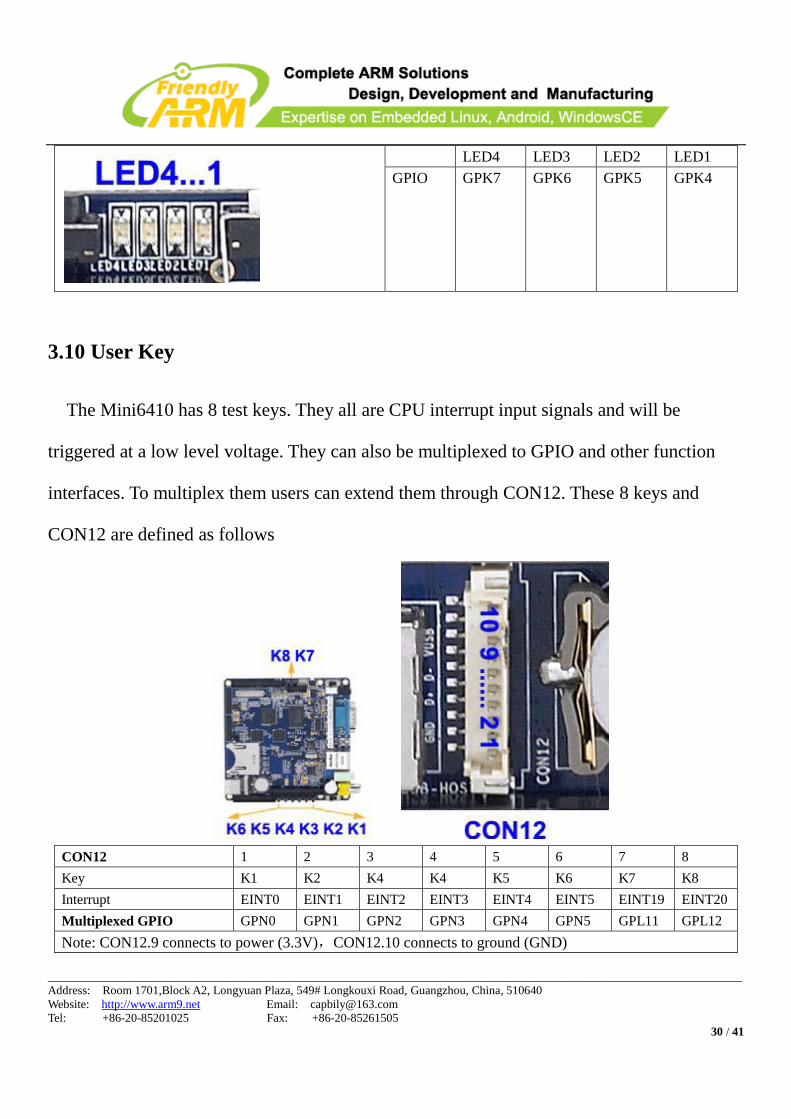
3.10 User Key
The Mini6410 has 8 test keys. They all are CPU interrupt input signals and will be
triggered at a low level voltage. They can also be multiplexed to GPIO and other function
interfaces. To multiplex them users can extend them through CON12. These 8 keys and
CON12 are defined as follows
CON12 1 2 3 4 5 6 7 8
Key K1 K2 K4 K4 K5 K6 K7 K8
Interrupt EINT0 EINT1 EINT2 EINT3 EINT4 EINT5 EINT19 EINT20
Multiplexed GPIO GPN0 GPN1 GPN2 GPN3 GPN4 GPN5 GPL11 GPL12
Note: CON12.9 connects to power (3.3V),CON12.10 connects to ground (GND)
____________________________________________________________________________________________________________________
Address: Room 1701,Block A2, Longyuan Plaza, 549# Longkouxi Road, Guangzhou, China, 510640
Website: http://www.arm9.net Email: [email protected]
Tel: +86-20-85201025 Fax: +86-20-85261505
31 / 41
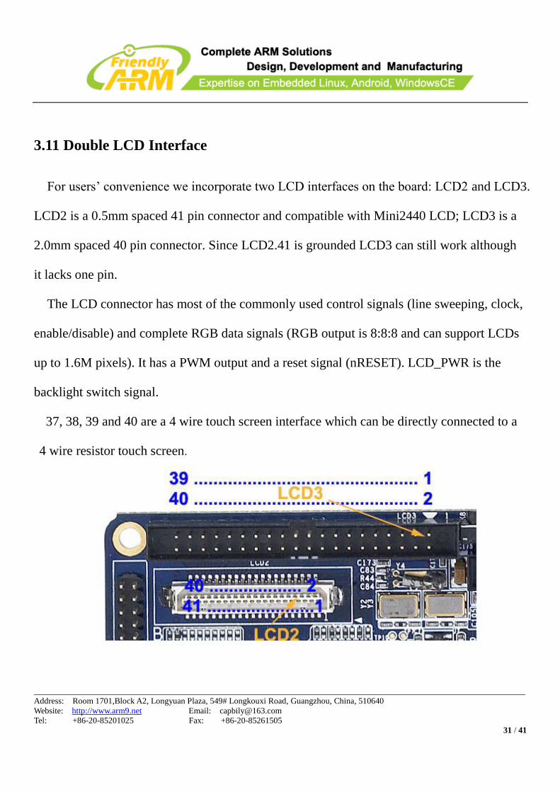
3.11 Double LCD Interface
For users’ convenience we incorporate two LCD interfaces on the board: LCD2 and LCD3.
LCD2 is a 0.5mm spaced 41 pin connector and compatible with Mini2440 LCD; LCD3 is a
2.0mm spaced 40 pin connector. Since LCD2.41 is grounded LCD3 can still work although
it lacks one pin.
The LCD connector has most of the commonly used control signals (line sweeping, clock,
enable/disable) and complete RGB data signals (RGB output is 8:8:8 and can support LCDs
up to 1.6M pixels). It has a PWM output and a reset signal (nRESET). LCD_PWR is the
backlight switch signal.
37, 38, 39 and 40 are a 4 wire touch screen interface which can be directly connected to a
4 wire resistor touch screen.
____________________________________________________________________________________________________________________
Address: Room 1701,Block A2, Longyuan Plaza, 549# Longkouxi Road, Guangzhou, China, 510640
Website: http://www.arm9.net Email: [email protected]
Tel: +86-20-85201025 Fax: +86-20-85261505
32 / 41
LCD2 & LCD3 PIN Spec LCD2 & LCD3 PIN Spec
1 5V 2 5V
3 VD0 4 VD1
5 VD2 6 VD3
7 VD4 8 VD5
9 VD6 10 VD7
11 GND 12 VD8
13 VD9 14 VD10
15 VD11 16 VD12
17 VD13 18 VD14
19 VD15 20 GND
21 VD16 22 VD17
23 VD18 24 VD19
25 VD20 26 VD21
27 VD22 28 VD23
29 GND 30 GPE0/LCD_PWR
31 PWM1/GPF15 32 nRESET
33 VDEN/VM 34 VSYNC
35 HSYNC 36 VCLK
37 TSXM 38 TSXP
39 TSYM 40 TSYP
41 GND
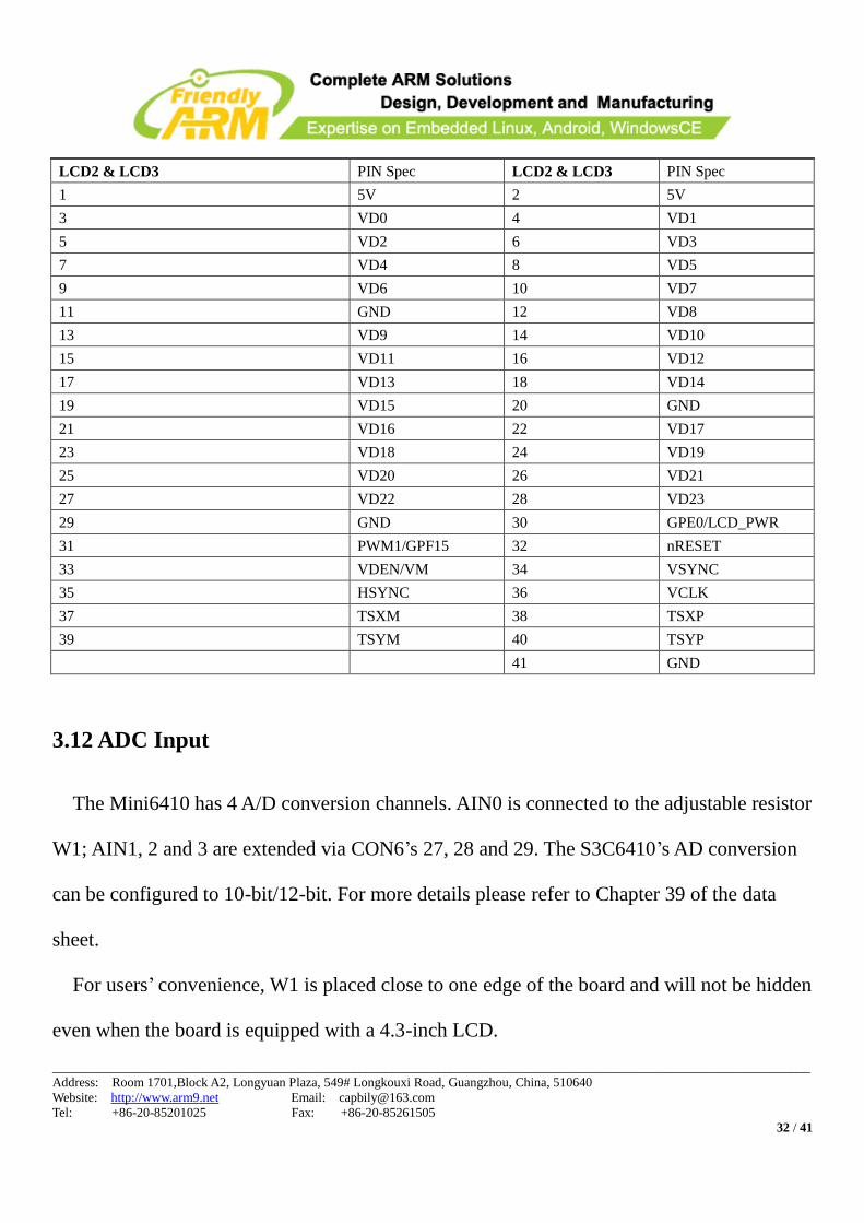
3.12 ADC Input
The Mini6410 has 4 A/D conversion channels. AIN0 is connected to the adjustable resistor
W1; AIN1, 2 and 3 are extended via CON6’s 27, 28 and 29. The S3C6410’s AD conversion
can be configured to 10-bit/12-bit. For more details please refer to Chapter 39 of the data
sheet.
For users’ convenience, W1 is placed close to one edge of the board and will not be hidden
even when the board is equipped with a 4.3-inch LCD.
____________________________________________________________________________________________________________________
Address: Room 1701,Block A2, Longyuan Plaza, 549# Longkouxi Road, Guangzhou, China, 510640
Website: http://www.arm9.net Email: [email protected]
Tel: +86-20-85201025 Fax: +86-20-85261505
33 / 41
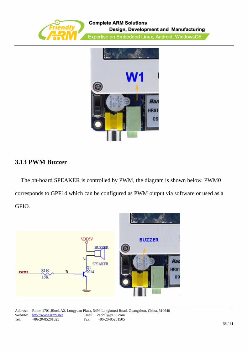
3.13 PWM Buzzer
The on-board SPEAKER is controlled by PWM, the diagram is shown below. PWM0
corresponds to GPF14 which can be configured as PWM output via software or used as a
GPIO.
____________________________________________________________________________________________________________________
Address: Room 1701,Block A2, Longyuan Plaza, 549# Longkouxi Road, Guangzhou, China, 510640
Website: http://www.arm9.net Email: [email protected]
Tel: +86-20-85201025 Fax: +86-20-85261505
34 / 41
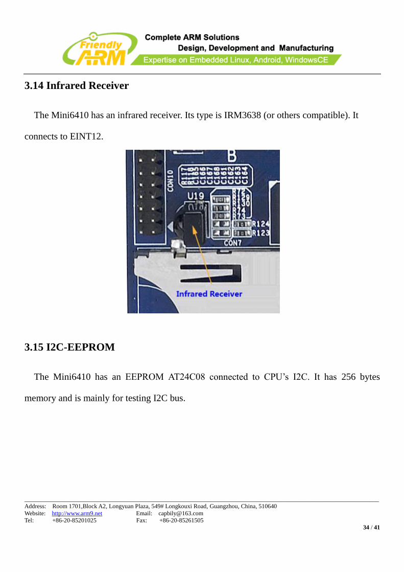
3.14 Infrared Receiver
The Mini6410 has an infrared receiver. Its type is IRM3638 (or others compatible). It
connects to EINT12.
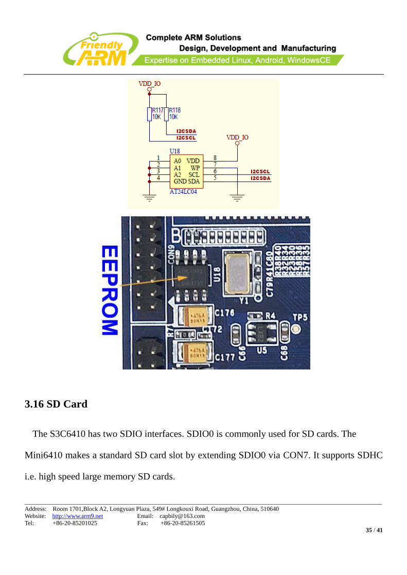
3.15 I2C-EEPROM
The Mini6410 has an EEPROM AT24C08 connected to CPU’s I2C. It has 256 bytes
memory and is mainly for testing I2C bus.
____________________________________________________________________________________________________________________
Address: Room 1701,Block A2, Longyuan Plaza, 549# Longkouxi Road, Guangzhou, China, 510640
Website: http://www.arm9.net Email: [email protected]
Tel: +86-20-85201025 Fax: +86-20-85261505
35 / 41
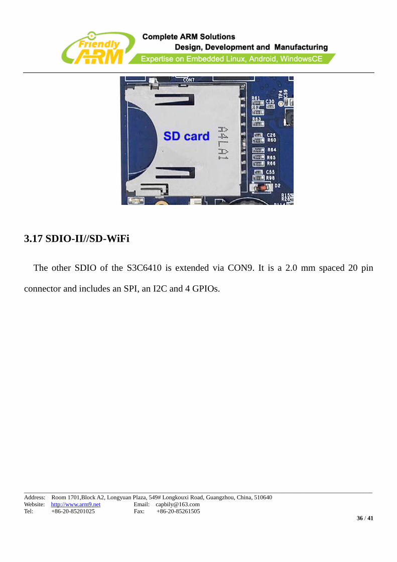
3.16 SD Card
The S3C6410 has two SDIO interfaces. SDIO0 is commonly used for SD cards. The
Mini6410 makes a standard SD card slot by extending SDIO0 via CON7. It supports SDHC
i.e. high speed large memory SD cards.
____________________________________________________________________________________________________________________
Address: Room 1701,Block A2, Longyuan Plaza, 549# Longkouxi Road, Guangzhou, China, 510640
Website: http://www.arm9.net Email: [email protected]
Tel: +86-20-85201025 Fax: +86-20-85261505
36 / 41
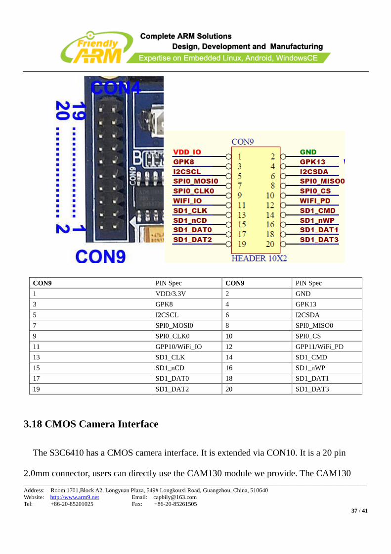
3.17 SDIO-II//SD-WiFi
The other SDIO of the S3C6410 is extended via CON9. It is a 2.0 mm spaced 20 pin
connector and includes an SPI, an I2C and 4 GPIOs.
____________________________________________________________________________________________________________________
Address: Room 1701,Block A2, Longyuan Plaza, 549# Longkouxi Road, Guangzhou, China, 510640
Website: http://www.arm9.net Email: [email protected]
Tel: +86-20-85201025 Fax: +86-20-85261505
37 / 41
CON9 PIN Spec CON9 PIN Spec
1 VDD/3.3V 2 GND
3 GPK8 4 GPK13
5 I2CSCL 6 I2CSDA
7 SPI0_MOSI0 8 SPI0_MISO0
9 SPI0_CLK0 10 SPI0_CS
11 GPP10/WiFi_IO 12 GPP11/WiFi_PD
13 SD1_CLK 14 SD1_CMD
15 SD1_nCD 16 SD1_nWP
17 SD1_DAT0 18 SD1_DAT1
19 SD1_DAT2 20 SD1_DAT3
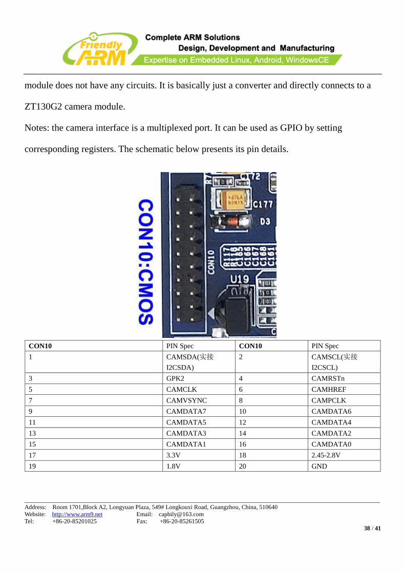
3.18 CMOS Camera Interface
The S3C6410 has a CMOS camera interface. It is extended via CON10. It is a 20 pin
2.0mm connector, users can directly use the CAM130 module we provide. The CAM130
____________________________________________________________________________________________________________________
Address: Room 1701,Block A2, Longyuan Plaza, 549# Longkouxi Road, Guangzhou, China, 510640
Website: http://www.arm9.net Email: [email protected]
Tel: +86-20-85201025 Fax: +86-20-85261505
38 / 41
module does not have any circuits. It is basically just a converter and directly connects to a
ZT130G2 camera module.
Notes: the camera interface is a multiplexed port. It can be used as GPIO by setting
corresponding registers. The schematic below presents its pin details.
CON10 PIN Spec CON10 PIN Spec
1 CAMSDA(实接
I2CSDA)
2 CAMSCL(实接
I2CSCL)
3 GPK2 4 CAMRSTn
5 CAMCLK 6 CAMHREF
7 CAMVSYNC 8 CAMPCLK
9 CAMDATA7 10 CAMDATA6
11 CAMDATA5 12 CAMDATA4
13 CAMDATA3 14 CAMDATA2
15 CAMDATA1 16 CAMDATA0
17 3.3V 18 2.45-2.8V
19 1.8V 20 GND

____________________________________________________________________________________________________________________
Address: Room 1701,Block A2, Longyuan Plaza, 549# Longkouxi Road, Guangzhou, China, 510640
Website: http://www.arm9.net Email: [email protected]
Tel: +86-20-85201025 Fax: +86-20-85261505
39 / 41
3.19 GPIO
GPIO is the abbreviated form of General Purpose Input Output. The Mini6410 has a 30 Pin
2.0mm spaced GPIO interface, i.e. CON6. In fact, CON6 has not only quite a few GPIO pins
but also some CPU pins such as AD input, DAC and so on. The SPI interface, I2C interface,
interrupts and some others are all GPIOs, but they are marked as special function interfaces.
They can be configured for other purposes too by setting related CPU registers.
CON6 PIN Spec Description CON6 PIN Spec Description
1 3.3V Power 2 GND Ground
3 GPE1 Available, can be used as
GPIO
4 GPE2 Available, can be used as
GPIO
5 GPE3 Available, can be used as
GPIO
6 GPE4 Available, can be used as
GPIO
7 GPM0 Available, can be used as
GPIO
8 GPM1 Available, can be used as
GPIO
9 GPM2 Available, can be used as
GPIO
10 GPM3 Available, can be used as
GPIO
11 GPM4 Available, can be used as
GPIO
12 GPM5 Available, can be used as
GPIO
13 GPQ1 Available, can be used as
GPIO
14 GPQ2 Available, can be used as
GPIO
15 GPQ3 Available, can be used as
GPIO
16 GPQ4 Available, can be used as
GPIO
17 GPQ5 Available, can be used as 18 GPQ6 Available, can be used as
____________________________________________________________________________________________________________________
Address: Room 1701,Block A2, Longyuan Plaza, 549# Longkouxi Road, Guangzhou, China, 510640
Website: http://www.arm9.net Email: [email protected]
Tel: +86-20-85201025 Fax: +86-20-85261505
40 / 41
GPIO GPIO
19 SPI1_CLK Available, can be used as
GPIO
20 SPI1_MISO Available, can be used as
GPIO
21 SPI1_CS Available, can be used as
GPIO
22 SPI1_MOSI Available, can be used as
GPIO
23 EINT6 Available, can be used as
GPIO
24 EINT9 Available, can be used as
GPIO
25 EINT11 Available, can be used as
GPIO
26 EINT16 Available, can be used as
GPIO
27 AIN1 Analog input1, 0-0.3.3V 28 AIN2 Analog input2, 0-0.3.3V
29 AIN3 Analog input3, 0-0.3.3V 30 DACOUT1
Note: DACOUT1 is TV output. It needs to be connected to a magnifier for TV output
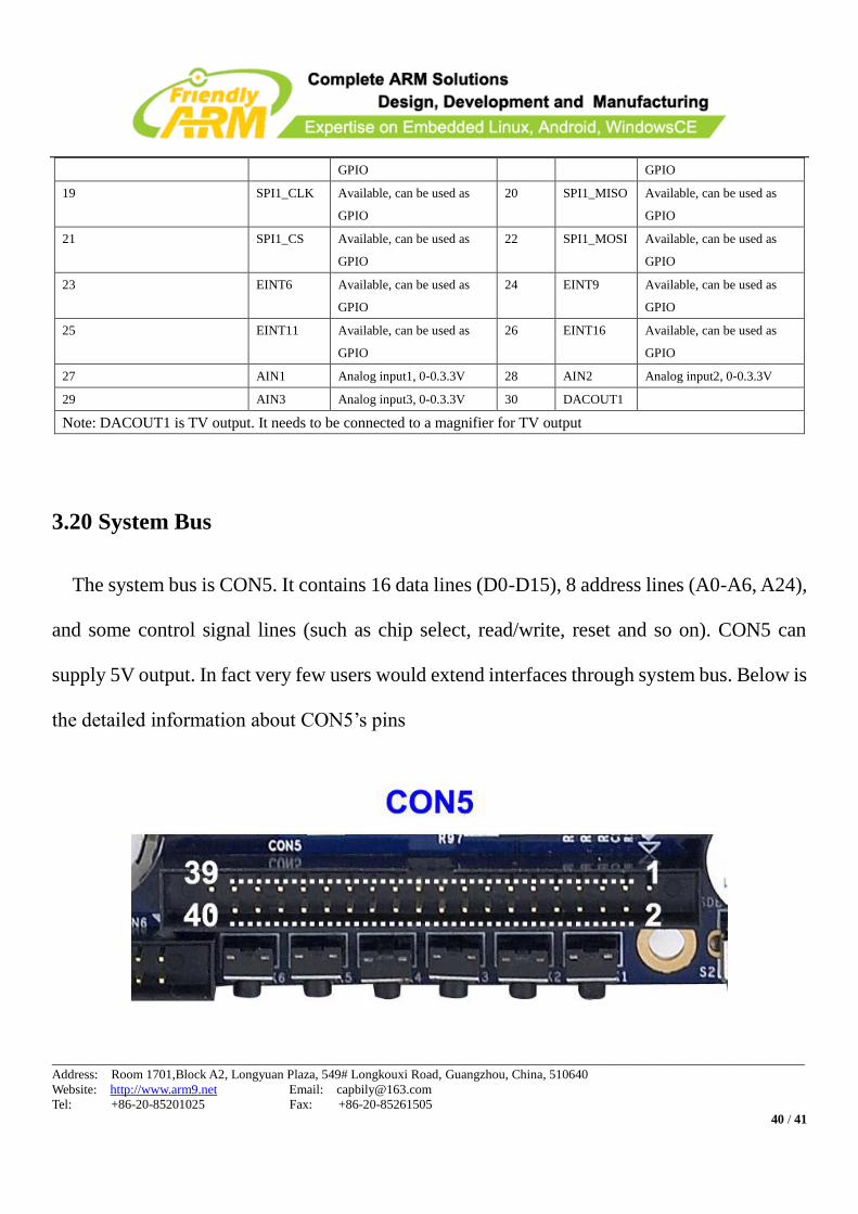
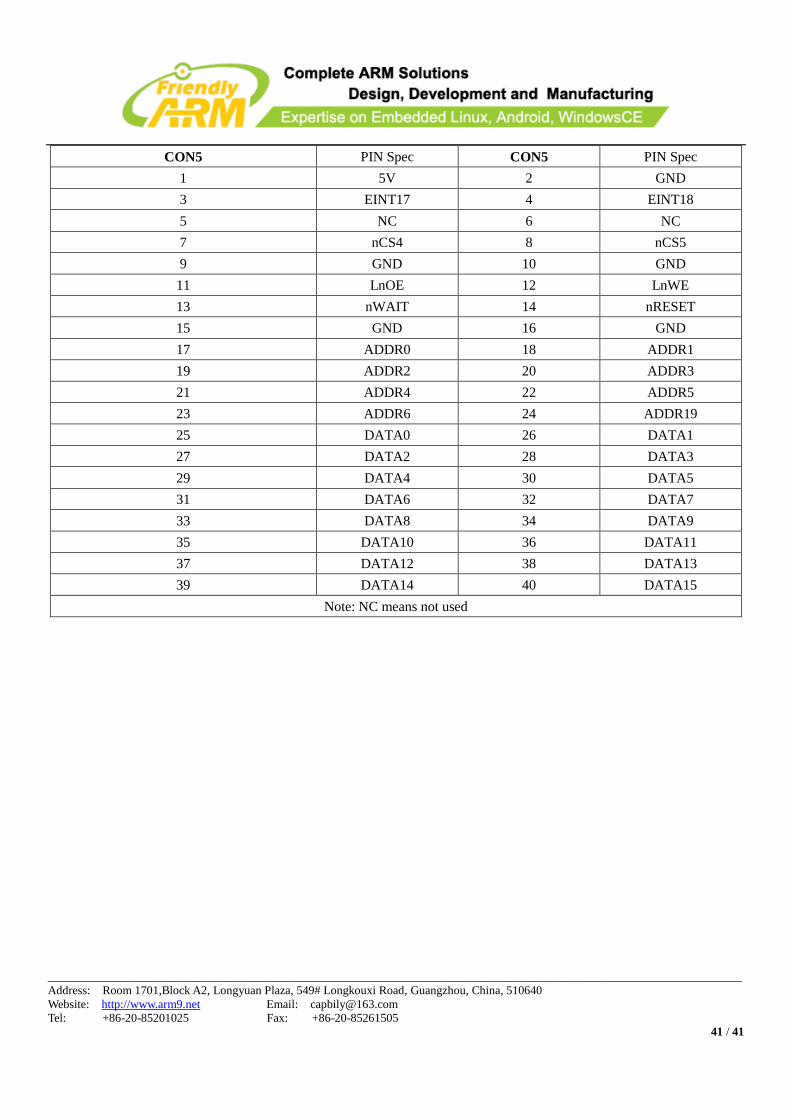
3.20 System Bus
The system bus is CON5. It contains 16 data lines (D0-D15), 8 address lines (A0-A6, A24),
and some control signal lines (such as chip select, read/write, reset and so on). CON5 can
supply 5V output. In fact very few users would extend interfaces through system bus. Below is
the detailed information about CON5’s pins
____________________________________________________________________________________________________________________
Address: Room 1701,Block A2, Longyuan Plaza, 549# Longkouxi Road, Guangzhou, China, 510640
Website: http://www.arm9.net Email: [email protected]
Tel: +86-20-85201025 Fax: +86-20-85261505
41 / 41
CON5 PIN Spec CON5 PIN Spec
1 5V 2 GND
3 EINT17 4 EINT18
5 NC 6 NC
7 nCS4 8 nCS5
9 GND 10 GND
11 LnOE 12 LnWE
13 nWAIT 14 nRESET
15 GND 16 GND
17 ADDR0 18 ADDR1
19 ADDR2 20 ADDR3
21 ADDR4 22 ADDR5
23 ADDR6 24 ADDR19
25 DATA0 26 DATA1
27 DATA2 28 DATA3
29 DATA4 30 DATA5
31 DATA6 32 DATA7
33 DATA8 34 DATA9
35 DATA10 36 DATA11
37 DATA12 38 DATA13
39 DATA14 40 DATA15
Note: NC means not used