Embed Size (px)
Citation preview

Spring 2009
Forrest Hubler Brass Sears Scott Clark Robert GassoIntel Sponsor: Jered Wikander Academic Advisor: Dr Wern Spring 2009
Miniature Air Moving Device: Final Report

Miniature Air Moving Device: Final Report
Executive Summary
Cooling components within electronic devices is largely accomplished through convection. Traditional technology to move air for convection within these devices utilizes fans. The goal of this project was to design and prototype a miniature, non-traditional air movement device that would achieve volume transport, velocity, and pressure benchmarks set by current fans. This document traces the final evolution of the Minimover, a non-traditional air movement device that was the result of a focus on simplicity, durability, and effectiveness. Difficulties encountered included, 1) moving air within a 3 mm space and, 2) channeling air flow once it was achieved. Ultimately, the final prototype was able to overcome these difficulties and achieve specified goals using a magnet-solenoid drive system, and one-way valves with no moving parts.
1

Miniature Air Moving Device: Final Report
Table of Contents: Page
Executive Summary 1
Introduction/Background Information 4
Mission Statement 4
Product Design Specifications 5
Top Level Design (Alternative Design Decisions) 5
Valves 5
Drive mechanism 7
“Bellows” 8
Detailed Design 9
Solenoid (Drive system) Design 9
Valve Design 11
Unit Package Design 12
Controls Design 14
Testing/Results 16
Conclusions and Recommendations 17
Appendix A: Product Design Specifications 19
Appendix B: Internal Search Results 20
Appendix C: Concept Evaluation and Selections 26
Appendix D: Solenoid Design and Calculations 28
2

Miniature Air Moving Device: Final Report
Appendix E: Material Technical Data 30
Appendix F: Package Design 31
Appendix G: Initial Prototype Test Results 32
Appendix H: Design Drawings 35
Appendix I: Control System Design 37
Appendix J: Final Design Test Results 38
Appendix K: Bill of Materials and Cost Analysis 39
Appendix L: Design Assembly Instructions 41
3

Miniature Air Moving Device: Final Report
IntroductionIntel Corporation is the world’s largest semiconductor manufacturer and the inventor of
the x86 microprocessor, found in the majority of the world’s personal computers. Within Intel, the Mobile Platforms Group is responsible for investigating and developing promising new technologies specifically for implementation in mobile electronic devices such as laptop computers and handheld electronic devices. These smaller devices encompass an ever increasing percentage of world-wide computer and electronics sales.
As manufacturers seek to decrease the size of electronic devices without reducing their performance, the need for smaller components grows. Especially important is any technology that facilitates the cooling of these components within the device. Desktop PC’s, and many larger electronic devices, are capable of using relatively large axial fans that can sit vertically due to relatively few size constraints. As computers decrease in size, more specifically in thickness, radial fans or blowers that have been flattened are traditionally used to move air and cool components through convection. Some of these current miniature blowers have a footprint of less than a dime and operate in a space 6mm high. Blowers can be made increasingly smaller, but the technology is primitive and the efficiency is static.
Intel is actively exploring new methods of air movement on an even smaller scale. The goal of this project was to produce an air moving device that that fit into and moved air through a space 3mm high, with limited decrease in air volume transport, air speed, and pressure with respect to current technology.
Mission Statement
The goal of this research project was to design and prototype a non-traditional miniature air-moving device, operating in a space 3mm high and satisfing air-flow and design specifications requirements set forth by Intel.
4

Miniature Air Moving Device: Final Report
Product Design Specifications
Highest priority specifications mandated that the device operate according to the following specifications:
- Maximum 3mm height
- An air volume transport of 0.01-0.1 ACFM (Cubic Feet per Minute)
- A pressure range of 0.01-0.05 Inches of Water
- An air velocity between 0.1-1 m/s (Meters per Second)
- Utilize new or non-traditional methods of moving air
Lower priority design specifications that were focused on:
- Power supply of less than 18V (laptop battery)
- Footprint of less than 200 x 300 mm
- Able to function in nominal, or average inside, operating conditions
- Able to withstand a three foot drop
- Total cost of the device less than two dollars per unit.
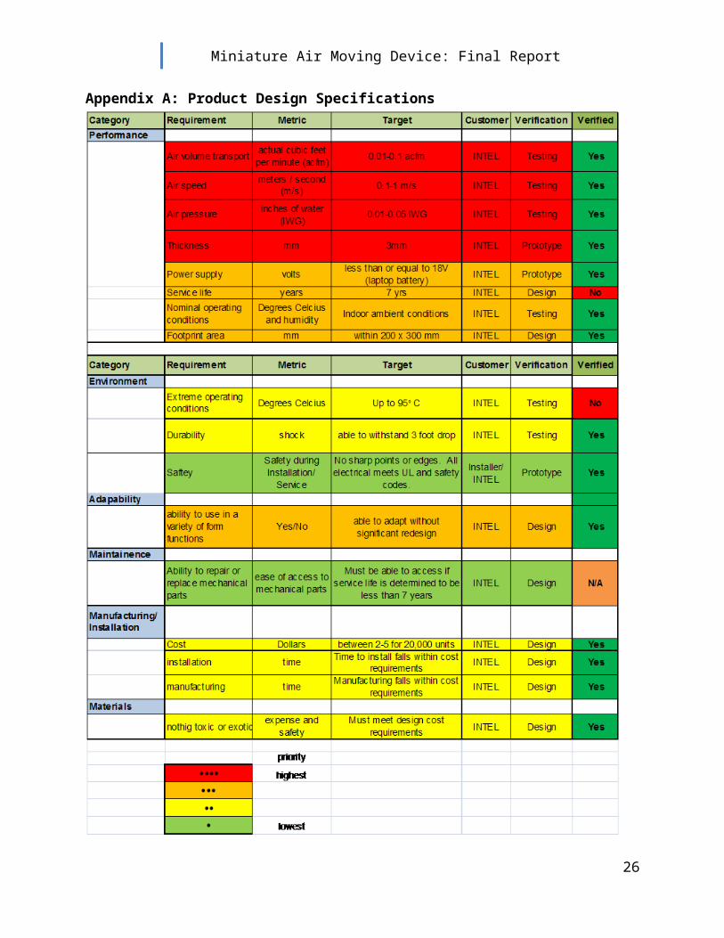
A complete list of the detailed design specifications according to priority and metrics, as discussed in the Product Design Specification Report (Feb 6th, 2009) are provided in Appendix A.
Top Level Design
Reviewing the device concepts (Appendix B), we were able to come up with a rendition of the parachute pump (Appendix C) we felt would be easier to prototype and manufacture than the other initial concepts. The main aspects of the parachute concept that would need to be evaluated and designed included valve design, drive system, and the “bellows” or piston and cylinder design.
Valves
The first hurdle to overcome in the design was limiting air flow to one direction. An external search of currently available, one-way valves, resulted in zero results that fit within the device constraints. Initial designs for creating our own valves revolved around “laser cut”
5

Miniature Air Moving Device: Final Report
plastic flap valves that would open for air flow in only one direction (Figure 1). These “flaps” were to be made of a thin plastic which would be glued into the openings of the device. Ultimately, due to the size constraints, the difficulty in gluing in the valves, and longevity of the device, we decided, that if possible, the cleanest design for moving air would involve a minimum of moving parts and no assembly.
Figure 1: Early prototype of the air movement device with valves created by sandwiching pre-cut flexible plastic to control air movement in one direction.
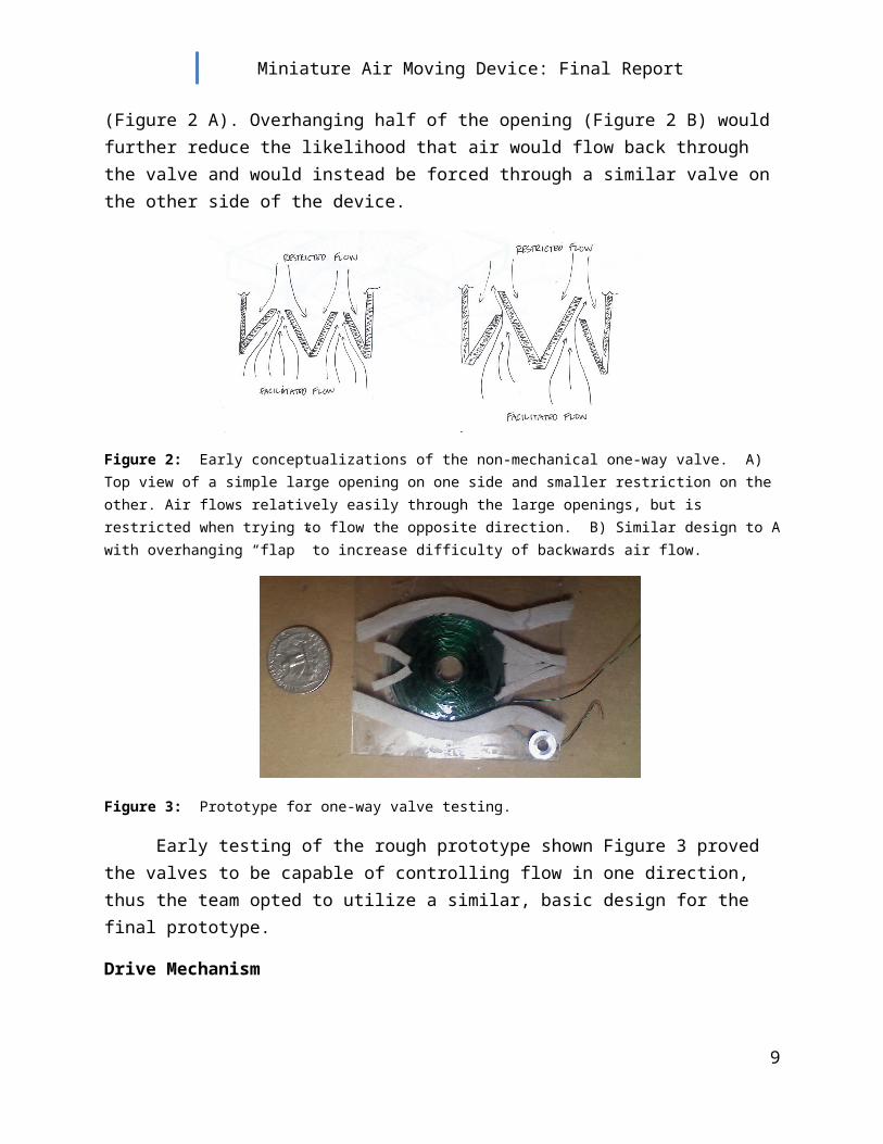
Research into valve design that would control flow without mechanical and moving parts lead to the concept of passages for air movement with large inlets and smaller overlapping outlets that would promote air flow in one direction. Conceptually, air would flow with relative ease into the pumping chamber through large openings in the direction of desired flow. Air flow in the opposite direction would be restricted by the smaller opening (Figure 2 A). Overhanging half of the opening (Figure 2 B) would further reduce the likelihood that air would flow back through the valve and would instead be forced through a similar valve on the other side of the device.
Figure 2: Early conceptualizations of the non-mechanical one-way valve. A) Top view of a simple large opening on one side and smaller restriction on the other. Air flows relatively easily through the large openings, but is restricted when trying to flow the opposite direction. B) Similar design to A with overhanging “flap” to increase difficulty of backwards air flow.
6
A) B)

Miniature Air Moving Device: Final Report
Figure 3: Prototype for one-way valve testing.
Early testing of the rough prototype shown Figure 3 proved the valves to be capable of controlling flow in one direction, thus the team opted to utilize a similar, basic design for the final prototype.
Drive Mechanism
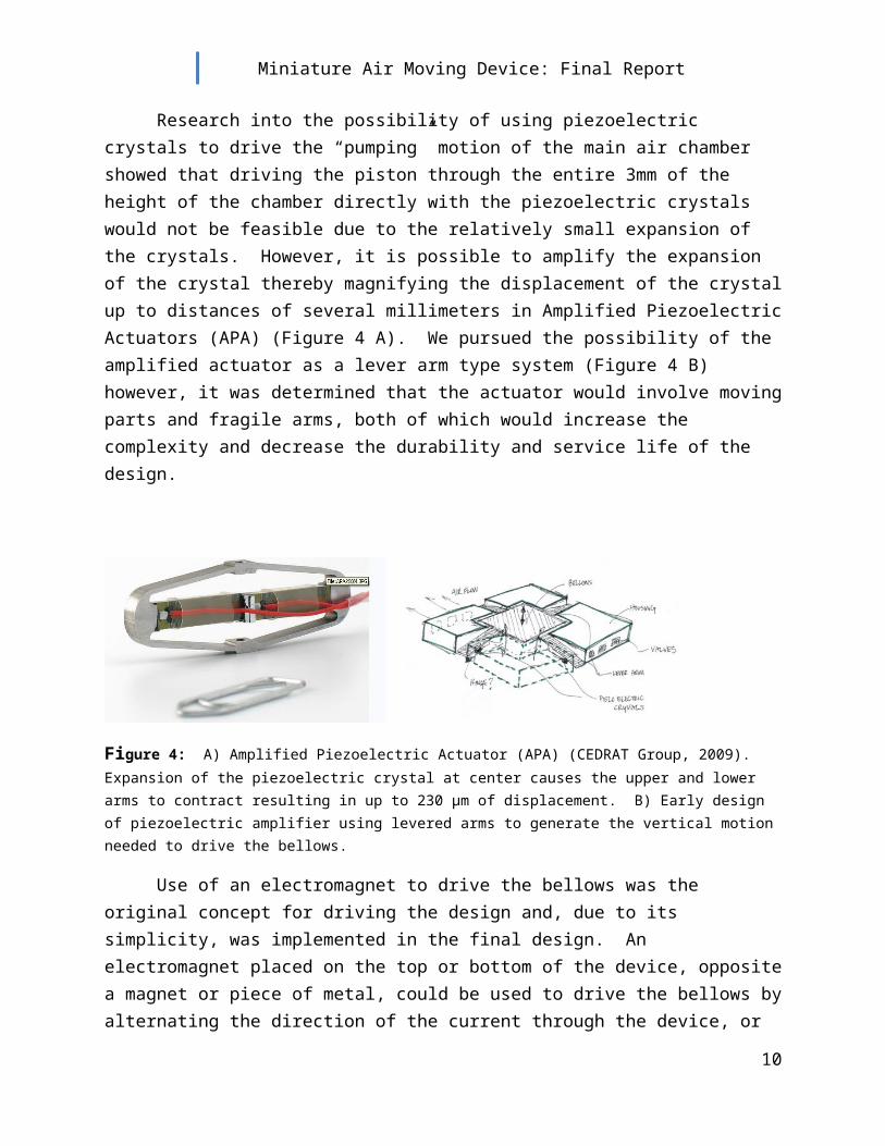
Research into the possibility of using piezoelectric crystals to drive the “pumping” motion of the main air chamber showed that driving the piston through the entire 3mm of the height of the chamber directly with the piezoelectric crystals would not be feasible due to the relatively small expansion of the crystals. However, it is possible to amplify the expansion of the crystal thereby magnifying the displacement of the crystal up to distances of several millimeters in Amplified Piezoelectric Actuators (APA) (Figure 4 A). We pursued the possibility of the amplified actuator as a lever arm type system (Figure 4 B) however, it was determined that the actuator would involve moving parts and fragile arms, both of which would increase the complexity and decrease the durability and service life of the design.
Figure 4: A) Amplified Piezoelectric Actuator (APA) (CEDRAT Group, 2009). Expansion of the piezoelectric crystal at center causes the upper and lower arms to contract resulting in up to 230 μm of displacement. B) Early design of piezoelectric amplifier using levered arms to generate the vertical motion needed to drive the bellows.
7
A) B)

Miniature Air Moving Device: Final Report
Use of an electromagnet to drive the bellows was the original concept for driving the design and, due to its simplicity, was implemented in the final design. An electromagnet placed on the top or bottom of the device, opposite a magnet or piece of metal, could be used to drive the bellows by alternating the direction of the current through the device, or by simply turning the current on and off in a sinusoidal or square-wave pattern. A flexible membrane could then be added to increase the efficiency of the design by increasing the area of air forced out of the chamber and assisting, or supplying, the force required to return the magnet to its “at rest” position.
Disadvantages of the design that were discussed were, 1) the possibility of high currents needed to generate the electromagnetic field and, 2) the heat that might be associated with high currents. Another concern was the addition of a magnetic field to a sensitive electronic device. However, after consulting Jered Wikander at Intel, it was agreed that the project should focus on the air movement by whatever means possible and shielding during packaging of the device would alleviate the effects of the magnetic field.
“Bellows”
The team focused on one of two design options for the “bellows,” or chamber in which the pressure difference for generating the drive is created. The first option was created by a flexible material attached to the magnet that moved up and down as a piston within a “cylinder” (Figure 5 A). The second was a more traditional “bellows,” much like an accordion, that utilized a magnet with flexible sides to control air loss as the magnet is cycled (Figure 5 B). Ultimately, the piston-cylinder design allowed for easy integration with the valves and an overall package that would be easy to install and manufacture. By beveling the cylinder walls to mimic the displaced shape of the flexible material a greater percentage of the entire volume of air would be forced out of the chamber.
Figure 5: Bellows concepts. A) Fixed flexible material with attached magnet piston and B) bellows design with flexible or folded sides attached to the piston.
8
A) B)
Miniature Air Moving Device: Final Report
Detailed Design
Upon deciding on the final mechanics of the device the team set out to address the integration of the different components.
Solenoid Drive System:
Because the heart of the device is an electromagnet, its design was of primary concern. Approximation of a planar coil was calculated to be the summation of many single wire loops. Using a derivation of the Biot-Savart Law the magnetic strength of a planar coil was approximated by adding the strength of all of the single coil fields within the solenoid (see Appendix E). For a 1.25 inch coil made by winding 24 AWG wire with a current of 1A, the strength of the field at the coil’s center is 1.92 Gauss. By contrast, the magnetic strength at the surface of a Neobydium magnet, 1 inch in diameter, with a thickness of 0.03125 inches, is 1470 Gauss.
Based on these calculations, and tests conducted by running various currents through a solenoid, it was determined that the object to be attracted by the solenoid would have to be a magnet, which would have its own magnetic strength, as opposed to a thin piece of sheet metal, which would rely entirely upon the strength of the fairly week field produced by the solenoid.
Initial testing was conducted on solenoids utilizing wires of various diameters and insulators (Figure 6). Melting was observed on most of the plastic insulators due to the heat generated by the current. Enamel coated wire is traditionally used in electric motors, and designed to carry high current without melting, which made it the ultimate choice for the solenoids. Prototypes of different diameters were also tested. Ultimately, the strength of the solenoid depends on the number of coil loops and the current running through the loop. A compromise was made between a large diameter wire, which would allow for more current, and small diameter wire, which would allow for a thinner electromagnet and more loops within the limited coil diameter. 24 AWG wire has a 0.51 mm diameter which leaves roughly 2.5 mm height in the pump chamber for piston motion to generate pumping action.
9
Miniature Air Moving Device: Final Report
Figure 6: Prototype solenoid magnets. A) Enamel coated copper wire (22 AWG) in tape, and B) plastic coated copper wire (22 AWG) in tape, C) Enamel coated 24 AWG wire in epoxy resin.
Overall diameter of the solenoid was determined through testing with the largest obtainable magnet at an acceptable thickness of roughly 0.5 mm. It was determined that the solenoid should be at least as large as the magnet to provide the needed strength. Sizing the diameter of the solenoid slightly larger than the magnet diameter had no noticeable effects on the operation of the system, so an overall diameter of 1.25 inches was selected.
Finally, epoxy Resin was poured over the solenoids and pressed so that the final thickness of the coils was equal to the thickness of the 24 AWG wire (~0.5 mm). Excess Epoxy was cut away to size the coil for the device.
Neobydium magnets were selected due to their strength. In order to maximize volume transport, the team chose to utilize a 1 inch diameter magnet, the largest available in a 1/32 Inch thickness. Main considerations for determining the shape of the magnet were the repeated cycling of the membrane and magnets. A circular shape was selected as the form that would cause the least amount of wear on the flexible material of the membrane. A Nickel coating was selected in order to ensure the smoothest surface on the magnet as another step in reducing wear.
Latex was selected as the membrane due to its flexibility, durability, and availability in varying thicknesses. Its flexibility was important for allowing the full motion of the piston in the cylinder, and its strength would assist in restoring the magnet to its neutral position. The thinnest latex available was 4mil (~0.1mm) which would take up the least vertical space and allow for the maximum motion of the piston. Tech sheets for the magnets and Latex membrane can be found in Appendix E.
10
A) B) C)

Miniature Air Moving Device: Final Report
Valve Design:
The one-way valves were designed based on the configurations in Figure 2 of the Top Level Design section. A prototype (as shown in Figure 3, Top Level Design) was made using closed cell foam to create the shape of the valves and the cavity. Due to the promising performance of the prototype in testing, two different versions of the prototype were created using Stereolithography (SLA) technology for further testing.
An alternative design was created based on technology developed in the Tesla Valve. The Tesla Valve (Figure 7) is a miniature control valve that contains no moving parts. Theory behind the valve is based on relatively unhindered fluid flow in the desired direction. When fluid flows in the unwanted direction, the fluid is pushed through an alternate channel and back into the main channel at a angle perpendicular, or larger than 90 degrees, to the main channel so that fluid flow is complicated and thus restricted.
Figure 7: The Tesla Valve. A) Fluid flow in the desired direction is relatively unhindered, and B) fluid flow in undesired direction is slowed by complicated flows created at the channel intersection. The angle of intersection can be increased so that the Tesla channel intersects at a direction that is more opposite flow in the main channel, further inhibiting flow in the undesired direction.
Based on this same theory, we designed prototype (Figure 8) with a Tesla-like valve on the air intake-side. Once air entered the main chamber, and the electromagnet caused the collapse of the chamber forcing air out, the flow would be inhibited from flowing back out of the intake-side with the Tesla channels, and thereby move more freely move out of the unrestricted, exit-side of the device.
11
A) B)

Miniature Air Moving Device: Final Report
Figure 8: Tesla valve prototype. Tesla channels in the entrance side force air in a perpendicular direction to main channel flow inhibiting flow out the entrance forcing air to flow out the path of least resistance and the exit. Ultimately, the increased openings (area circled in red) probably decreased the some propensity for air to flow out the exit-side of the device resulting in lower overall performance when compared to non-Tesla versions.
Laboratory testing of the Tesla prototype resulted in lower air velocity and volume transport than non-Telsa versions (Table 1). These lower velocities are attributed to the increased area and openings in the inlet side of the Telsa version.
Non-Telsa valve Tesla valveFrequency Voltage Velocity Velocity
Hz Volts m/s m/s30 1 0.30 0.0830 1 0.35 0.1130 1 0.32 0.1030 1 0.37 0.09
Table 1: Early test results for comparing the Telsa and Non-Tesla valves. The Tesla version produces air velocities on the order of a third of the Non-Tesla version.
Package Design:
12

Miniature Air Moving Device: Final Report
With anticipated difficulty in moving air in such a small space, it was decided to scale the device as large as possible with the opportunity to reduce the overall size if the volume transport target was realized. The size of the cylinder was mandated by the size of the magnet. The valves were sized according to a size relative to the cylinder. An overall length of 3 inches allowed for the inclusion of the 1.25 cylinder and valves on either side that were just less than 1 inch each. Testing of the rough prototype displayed promise in the ability of valves of this size to control air flow in one direction.
Width of the device was limited by the 1.25 inch cylinder diameter and the size of the valve inlets. A larger inlet translated into the possibility of more volume transport. Ultimately, it was decided that overall size of the device should be an arbitrary 3 x 2.5 inches. A cut-out was made on the bottom the device to insert the solenoid into the assembly. This cut-out was determined by the thickness (0.5mm) and the diameter (1.25 in) of the solenoid. Detailed design of the package can be found in Appendix F.
The latex membrane was adhered across the top of the prototypes, and the magnet adhered in the center of the bellows chamber. By adhering the solenoid to the opposite side of the device, in its designed slot, current could be run through the solenoid to attract the magnet, thus forcing air out of the chamber. Turning the current off, the latex membrane restored the magnet to the top or neutral position, which would in turn draw air into the chamber.
Figure 9: Digital prototypes A and B. Shown is the base plate without the solenoid, membrane and magnet.
Initial tests of prototypes A and B were promising (Figure 9). Air velocities were within the target range, but air pressure and overall volume transport were low (Appendix G). One of the disadvantages of this design was the ability to get only one pulse of air per current cycle (due to the location of the valves on only one side of the latex membrane). Two steps were taken to overcome this flaw. First, it was determined that by moving the neutral (starting)
13
A) B)

Miniature Air Moving Device: Final Report
position of the magnet to the middle of the vertical space, valves could be located on either side of the membrane thereby allowing a pulse when the magnet was both rising and falling. Second, by alternating the current (offset equal to zero), rather than just turning the current on and off (offset equal to half the amplitude), would first attract the magnet to the solenoid on the bottom surface and then repel it to the top surface (eliminating the need for magnets on the top and bottom). The result was two air pulses per current cycle; one on the way down and another on the way back up. In addition, each of these pulses would move nearly the same volume as the single pulse version providing twice as much air transport.
Prototype C (Figure 10) was a modified version of Prototype A. The modifications included dividing the device in half (two plates 1.45 mm thick rather than one plate 2.9 mm thick) and inserting a latex magnet sandwich between the halves. The Valves in Prototype C were identical in shape to prototype A. The Final Prototype and Assembly drawings can be found in Appendix H.
Figure 10: Digital Assembly of Prototype C showing the final design. Prototype B was split in half and the magnet sandwiched in latex inserted between the two halves. From top to bottom: top plate, latex membrane, magnet, latex membrane, bottom plate, and solenoid.
Control system Design:
Although not part of the design requirements, the team also attempted to design the controls for the solenoid. Driving Prototypes A and B involved turning the current on and off through the electromagnet. This was accomplished using a Transistor that would turn the current on and off and a 555 Switch that would control the frequency of the transistor. Due to
14

Miniature Air Moving Device: Final Report
calculations in the bellows design (Appendix F), roughly 3 cycles per second were required to reach the target goal of 0.01 ACFM volume transport at 100% efficiency. Through initial prototype testing, it was ascertained that the most efficient operating frequency was in a range of 8 to 10 cycles per second and a voltage of 1.8V. Detailed design considerations can be found in Appendix I.
The controls for Prototype C involved an alternating current with zero offset. This could be accomplished with an Op-Amp to alternate the current. Design of this component was not completed. Tests show that using an alternating current, with a sine wave-form the device can be operated at much higher frequencies than the offset, square-wave pattern for Prototypes A and B. The highest, most efficient operating frequencies for Prototype C were 25 to 35 Hz, at a slightly lower voltage of 1.1V.
Figure 11 is a schematic of the operation of the Final Prototype as it functions when driven by the alternating current.
15
Figure 11: Controls of the Final Prototype C.
a) Magnet in neutral position.
b) Current is run through the solenoid attracting the magnet to the bottom surface. The air in the lower chamber is expelled and air is drawn into the upper chamber.
c) As the current is reversed the magnet is repelled towards the top of the device. Air in the upper chamber is expelled and air is drawn into the lower chamber.
d) Magnet is repelled to its apex. All air is expelled from the upper chamber. Bottom chamber is “full”.
e) Current reverses, magnet is attracted to the bottom and the cycle starts over.
a)
b)
c)
d)
e)

Miniature Air Moving Device: Final Report
Testing/Results
Laboratory testing of the prototypes was conducted in an Air flow chamber at Intel. Figure 12 shows the fan curves generated from the test. The results show a maximum measured air transport of 0.05 ACFM at low pressure of 0.002 IWG, and maximum generated pressure of 0.027 IWG at a low flow of 0.01 ACFM with the fan running at the optimum 30 Hz speed. Slightly less optimum speeds, of 25 and 35 Hz, also produced curves that fit within this range. Final test results can be found in Appendix J.
Figure 12: Generated Fan curve of Prototype C at 25, 30, and 35 Hz. The red box indicates the targeted values for the device. The linear nature of the curves (versus the more traditional “knee” shaped curves) is due to the low number of data points.
Velocity was measured with a TSI Air Velocity Transducer. The results can be seen in Table 2. The maximum measured velocity was 0.37 m/s.
Frequency Voltage VelocityHz Volts m/s30 1 0.330 1 0.3530 1 0.3230 1 0.37
Table 2: Velocity measurements for Prototype C.
16
Target curve area
Flat Fan AFC Test Results
0
0.005
0.01
0.015
0.02
0.025
0.03
0 0.01 0.02 0.03 0.04 0.05 0.06
Flow (ACFM)
Plen
um P
ress
ure
(IWG
)
30 Hz
35 Hz
25 Hz
Linear (30 Hz)
Linear (35 Hz)
Linear (25 Hz)

Miniature Air Moving Device: Final Report
Prototype C was able to run most efficiently at 1.3 V at a frequency of 30 Hz. The current measured during operation was 1.1 Amperes, resulting in a power use of 1.43 Watts. Views of the final prototype can be seen in Figure 13.
Figure 13: Final Prototype. On the left (top view), the device is mounted between two plates in a 3mm space. The photo on the right is the inside of the two plates without the magnet and latex membrane. Air flow would be from the bottom to top of the photo.
Conclusions and Recommendations
Moving air in such a small space is difficult to say the least, but can be accomplished. The success of Prototype C, which has been named Minimover, in the areas of air volume transport, pressure, and velocity, demonstrate the ability to match currently available technologies, albeit on a slightly larger scale. Minimover is cheap, effective, simple, and durable. The device fell within the price constraints and it is possible that mass production would reduce the price further. Its simplicity, which is believed to be the core of the design, lends to its durability. Appendix A contains the complete list of design specifications, methods of verifications, and whether or not those specifications were achieved.
Difficulties in design at this scale include procurement of technologies for controlling air flow and generating pressure differences needed to move air. Refinement of one-way valves, similar to those in the final design, would allow for further research into methods of driving air. More efficient valves could lead to scaled down versions of the Minimover, which would bring the design closer to realistic implementation in electronic devices. A major obstacle to overcome, not fully addressed by the team, would be the design of the mechanics of the device that would be simple enough to result in flawless operation and, a long life with nearly continuous service.
17

Miniature Air Moving Device: Final Report
While the Team is pleased with the success of the device, there are attributes of the design that merit attention. The first concern we had is the heat generated by the solenoid in operation. While the device was able to run for long intervals, the amount of heat generated over a long service life might lead to failure. In addition, the primary purpose of the device is the cooling of electronic components, and the heat added by the Minimover could possibly negate any benefits. A second concern is the large current needed to drive the electromagnet. A current of 1.1 A would quickly draw down many batteries used to power small electronic devices.
A solution to the heat generation and power consumption is the implementation of the Amplified Piezoelectric Actuator (APA). Although it might increase the complexity of the device, it is most likely that the use of an APA would generate less heat and require less power. The next step in the design would be the exploration of alternative driving mechanisms that would match the solenoids efficiency and challenge its simplicity.
The third and final concern with this design is the noise generated by the device. Ultimately, to be effectively incorporated into electronic devices there must be little or no sound from the device itself. The diaphragm-like nature of the Minimover lends itself to noise at the apex of each driving pulse of the magnet. It is also possible that if the travel of the magnet (or drive system of a piezoelectric actuator) was limited to stop before the top and bottom surfaces, some of the noise could be abated.
18

Miniature Air Moving Device: Final Report
Appendix A: Product Design Specifications
19

Miniature Air Moving Device: Final Report
Appendix B: Internal Search Results
Internal search
The following designs are a result of project brainstorming, for non-traditional air movement devices.
Screw Pump
Figure 1. Solid model of screw pump design.
The screw pump is a modified axial or mixed-flow type fan. Air enters the opening in a direction perpendicular to the blade axis of rotation where forward curved blades or vanes act to “grab” the air. The direction of the air is then forced into a flow parallel to the axis of rotation. The large pitch of the “screw” acts to accelerate the air in this direction. The profile of the vanes switches from curved forward to neutral and finally to curved backwards as the pitch of the “screw” increases. The effect of these changes acts to increase velocity and build pressure as the air moves to the end of the screw. At the end of the screw the air is force into a funnel which once again changes the direction of flow back to its original direction. The funnel also increases the velocity as the cross sectional area decreases at the exit.
The screw pump’s potentially small size is an advantage in for this application. The device foot-print could be kept under 5 x 30 mm. The design also allows for one motor to run two pumps set end to end. Many pumps could be used to achieve the desired flow rate. Driving the pumps could be accomplished with a small
stepper motor which would with minimal power requirements, also an advantage due to the limited power. There is only one moving part which reduces the potential failure of the device. All parts could be injection molded which is inexpensive, and assembly and installation would be quick and easy keeping cost low.
20

Miniature Air Moving Device: Final Report
Disadvantages of the design include the small diameter of the vanes and the size of the inlet which would effectively move less air than a radial fan with larger blades and inlet. The smaller diameter of the vanes would require an increase in rpm in order to achieve the same flow as a radial design, another disadvantage. Sealing the pump chamber to ensure air movement with the rotation of the blades relies on a boundary layer of air at the chamber wall which would lower the efficiency of the design and possibly decrease the pressure the pump was able to create. Finally, it is doubtful that the device could achieve the desired velocity even if the flow rate could be achieved by using many devices at once.
Parachute Pump
Figure 2. Rendering of parachute pump design.
The Parachute pump is a modified diaphragm pump. The diaphragm consists of a flexible membrane with a magnet adhered in the center. The membrane is stretched over short “walls” which contain one-way valves on opposite walls. The pump is actuated by alternating current to electromagnets above and below the membrane magnet. The alternating current causes the membrane to rise on the first half of the cycle, which pulls air into the chamber through the one-way valves. When the bottom electromagnet is “turned on” in the second half of the cycle, the membrane is force downward expelling the air from the chamber through the second set of valves.
Advantages of the design include relatively low power requirements, and ease of manufacturing. Air movement could be significant if the chamber is sized large enough, but is limited by the efficiency of the one-way valves and area of the inlets. However, material procurement, such as the tiny one-way valves, might prove difficult due to the nominal
21

Miniature Air Moving Device: Final Report
application dimensions and the durability of the flexible membrane will need to be analyzed as fatigue failure will be of concern as a seven year life span is requested.
Milking Machine
Figure 3. Drawing of milking machine design(View from top).
The flat pump is a 3mm thick box with miniature valves situated on the shorter sides. A movable, magnetic plate exists between the valves inside the box. Electromagnets on either side of the partition are used to pull the plate back and forth. Springs could be fixed to the plate for centering purposes when the magnets are not activated. By alternating current through the electromagnets, the plate is cycled back and forth, simultaneously pushing air out of one chamber and drawing air into the other. In this manner air output is continuous (two pulses of air per magnetic cycles), as opposed to the parachute design which only produces one pulse of air per magnetic cycle.
The benefits of this air movement device are the compact size, simplistic movement of air, ease of installation and concept validity. The pump takes up 3 square inches of space. Electromagnets are activated and deactivated by routing electricity from one magnet to the next. The installation is simple because it is a box that is packaged and wired directly to the circuit board like fans that are currently in service. The air volume transport is also adjustable according to the speed of the electromagnet cycle.
Disadvantages of this design include creating the air-tight seal between the partition and the inside of the box while limiting friction. This will be crucial to the efficiency of the fan. Another is finding an electro magnet that is less than 3mm in diameter. Lastly, finding readily available valves that are 3mm in diameter will be a challenge.
22

Miniature Air Moving Device: Final Report
Worm Device
The “Worm Device” pushes pockets of air horizontally through the plates due to a membrane which moves in a wave-like fashion. There are three iterations of the worm device, the mechanical worm, the membrane worm, and the magnet worm. All of these designs have the advantage of large potential inlet areas for maximum air movement.
Membrane Worm
Figure 4. Solid model of membrane worm design.
This Device was partially conceptualized from the workings of the human esophagus. The design moves air by semi-sinusoidal motion of a malleable material which captures air and pushes the air through the two parallel plates from one end to the other. The flexible material would be attached to the side, guide posts via mounting bars that spanned the width of the design, or by the insertion of ringlets into the sides of the material which would connect the material directly to the posts. Several methods of controlling the motion of the material have been proposed. One would rely on electromagnets which could be turned on and off to drive either the metal mounting bars or ringlets up and down. Another method of controlling the wave motion would be a lever system utilizing piezocrystals to raise and lower the material.
The strongest aspect of this design is that, when sealed, it pushes the entire volume of air exposed at the inlet through the device as opposed to most fans which, between the stator and blades, can only move 50% or less of the air in the space that the device is constructed in. The effect of the wave motion is that when one cycle begins to move through the inlet is again opened (the materials opposite side) as an inlet for the next cycle. The result is a continuous supply of air moving through the device at all times. Difficulties in the design include procuring the flexible material, and finding, or manufacturing, thin electromagnets or the lever systems to control the motion. Sealing the edges of the material is another obstacle to be overcome with this particular iteration. Finally, the device will last only as long as the membrane, so material selection is crucial in the design.
23

Miniature Air Moving Device: Final Report
Mechanical Worm
Figure 5. Solid model of mechanical worm design.
The mechanical worm substitutes the flexible membrane with a series of plates that expand and contract, while moving vertically in tracks, to simulate the sinusoidal motion. This design has an advantage over the membrane worm because it eliminates the difficulties of controlling a flexible material with the inflexible plates. Mechanics of operating the plates would be controlled in a similar manner to the membrane worm, and it has the same air movement qualities. The design of the device is simple in that it requires only one plate part (flipped and interlinked) and one side rail (same part both sides) be manufactured.
However, because of the spaces between the expanding plates some sort of flexible, non-permeable material, would be selected as to minimize air leakage. The design also suffers from air leakage around the outside of the plates. Manufacturing of the plates may prove difficult because of their small size and the life of the device is dependent upon the durability of the plates. Finally, the plates themselves are .5 mm thick, which potentially takes up more space than a thin material, decreasing the volume in which to move air.
24

Miniature Air Moving Device: Final Report
Magnet worm
Figure 6. Rendering of magnetic worm design.
The magnet worm uses a series of metal plates inserted into slots along the length of a flexible membrane with a cross section in the shape of the number eight. The shape of the membrane functions to seal the design, ensuring all air is moved in the desired direction by preventing escape of air around the outside of the plates. Electromagnets on the upper and lower plates alternate along the length of the design moving the plates first to the top and then back down in series. The results are pockets of air in the membrane forced in the desired direction. Once again, material procurement and the thickness of the electromagnets are weaknesses in the design.
25
Miniature Air Moving Device: Final Report
Appendix C: Concept Evaluation and Selections
Concept Evaluation
The design team used an evaluation method that consisted of initial screening, averaged team concept scoring matrix, and final team evaluation.
Initial Screening
Upon initial screening the ionic device was removed from consideration for further concept evaluation. The ionic device was deemed too costly and unproven to pursue. Four viable concepts remained after screening. These included the milk machine, parachute device, screw device, and the worm device. The worm device concept consisted of three different iterations.
Evaluation Criteria
The concepts were evaluated based on power draw, installation, cost, manufacturability, material procurement, and air volume transport. These criteria were weighted based on Intel’s specifications as can be seen on the product design specifications in Appendix B. For example, Air volume transport was of utmost concern and carried a weighting of forty percent. Power draw was a low priority for Intel and our team and carried a rating of ten percent. Each member of the design team rated the six concepts with an integer value of one thru five, with five being the best and one being the worst. The members’ evaluations were averaged to yield an unbiased concept selection. Table 1 represents the members’ averaged values for each concept along with the selection results. The concept selected using this method was the screw compressor.
Table 1: Averaged concept selection
26

Miniature Air Moving Device: Final Report
Final Team Evaluation
Final evaluation involved the process of evaluating each team members weighted values and averaging these values for a resultant team concept score. In this manner the milk machine and the worm device were tied with the highest score. Ultimately, the team chose the parachute device as a reasonable and adequate device to pursue.
27

Miniature Air Moving Device: Final Report
Appendix D: Solenoid Design and Calculations
Calculating the strength of the magnetic field of the planar coil can be estimated by approximating the planar coil as a series of wire loops. The magnetic field at the center of a wire loop (as derived from the Biot-Savart Law) in the units of Tesla is:
Where, μo is the permeability constant, I is the current running through the wire and R is the radius of the wire loop. To convert to Units of Gauss, 1 Tesla = 10,000 Gauss.
For the solenoid with an internal diameter of 0.25 inches and external diameter of 1.25 inches:
The number of coils can be estimated by dividing the radius of the coil by the diameter of the wire.
28

Miniature Air Moving Device: Final Report
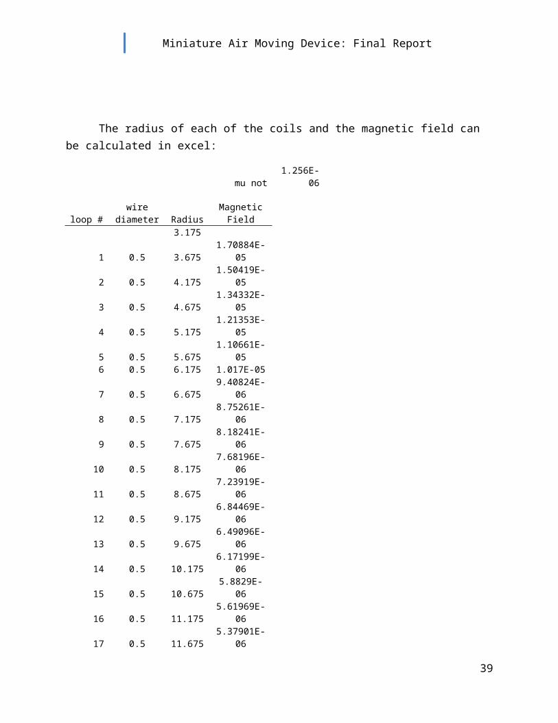
The radius of each of the coils and the magnetic field can be calculated in excel:
mu not 1.256E-06
loop #wire
diameter RadiusMagnetic
Field3.175
1 0.5 3.675 1.70884E-052 0.5 4.175 1.50419E-053 0.5 4.675 1.34332E-054 0.5 5.175 1.21353E-055 0.5 5.675 1.10661E-056 0.5 6.175 1.017E-057 0.5 6.675 9.40824E-068 0.5 7.175 8.75261E-069 0.5 7.675 8.18241E-06
10 0.5 8.175 7.68196E-0611 0.5 8.675 7.23919E-0612 0.5 9.175 6.84469E-0613 0.5 9.675 6.49096E-0614 0.5 10.175 6.17199E-0615 0.5 10.675 5.8829E-0616 0.5 11.175 5.61969E-0617 0.5 11.675 5.37901E-0618 0.5 12.175 5.15811E-0619 0.5 12.675 4.95464E-0620 0.5 13.175 4.7666E-0621 0.5 13.675 4.59232E-0622 0.5 14.175 4.43034E-0623 0.5 14.675 4.27939E-0624 0.5 15.175 4.13839E-0625 0.5 15.675 4.00638E-06
0.000192915 Teslaor
1.929147025 Gauss
The strength of the solenoid at the center is approximately 1.93 Gauss.
29

Miniature Air Moving Device: Final Report
Appendix E: Package Design
Package Design:
With anticipated difficulty in moving air in such a small space, we decided to scale the device as large as possible with the opportunity to reduce the overall size if the volume transport target was realized. The size of the cylinder was mandated by the size of the magnet. Based on the 25.4 mm (1 inch) magnet, a height of 3mm, and a rise angle of 45 degrees, the top of the cylinder was calculated to be 31.4 mm, which is approximately 1.25 inches (Figure 12). The volume of the cylinder was calculated to be 1900 mm3. Based on a target of 0.1 cfm, it was calculated that the device needed to cycle at 3 Hz to achieve our goal at 100 percent efficiency.
Figure 12: Cylinder Sizing schematic (all dimensions in mm). Size of the cylinder opening was determined by a 1 inch diameter magnet and material stretch at 45 degrees from a height of 3mm.
The valves were sized according to a size relative to the cylinder. An overall length of 3 inches allowed for the inclusion of the 1.25 cylinder and valves on either side that were just less than 1 inch each. Testing of the rough prototype displayed promise in the ability of valves of this size to control air flow in one direction.
Width of the device was limited by the 1.25 inch cylinder diameter and the size of the valve inlets. A larger inlet translated into the possibility of more volume transport. Ultimately, it was decided that overall size of the device should be an arbitrary a 3 x 3 inches.
A cut out was made on the bottom the device to insert the solenoid into the assembly. This cut out was determined by the thickness (0.5mm) and the diameter (1.25 in) of the solenoid. Detailed drawings of the prototypes can be found in Appendix G.
30

Miniature Air Moving Device: Final Report
Appendix F: Initial Prototype Test Results (5/22/09)
These results were taken at Intel with a TSI air velocity transducer. Various frequencies, wave forms, and restrictions on the vertical deflection of the magnet were applied. Larger deflections allow for more volume transport with each flow, resulting in higher velocities. The location describes the channel measured from (right or left side of the outlet or inlet side).
31
Instrument Name Air Velocity Transducer Run
Air Speed Recorded (m/s) Frequency Location
Wave Form Voltage
Vertical Deflection Restriction
Voltage Offset
By TSI 1 0.006 8hz Right Side Square 1.8 3mm 1.8Time Constant 10 sec 2 0.005 8hz Right Side Square 1.8 3mm 1.8Range 0-10000 ft/min 3 0.002 10hz Left Side Square 1.8 3mm 1.8Voltage 0-5V 4 0.0025 10hz Right Side Square 1.8 3mm 1.8Model 8465-09 5 0.001 7hz Right Side Square 1.8 3mm 1.8Serial 56090460 r.A 6 0.001 7hz Right Side Sine 1.8 3mm 1.8
7 0 7hz Right Side Sine 1.8 3mm 1.8Intel Air Flow Test 8 0.055 8hz Right Side Square 1.8 10mm 1.8
9 0.111 8hz Right Side Square 1.8 10mm 1.8Date 5/21/2009 10 0.15 8hz Left Side Square 1.8 10mm 1.8Time 7:30PM 11 0.17 8hz Right Side Square 1.8 6mm 1.8
12 0.08 8hz Right Side Square 1.8 6mm 1.813 0.02 8hz Inlet Square 1.8 6mm 014 0.25 8hz Right Side Square 1.8 6mm 0

Miniature Air Moving Device: Final Report
Appendix G: Design Drawings
32

Miniature Air Moving Device: Final Report
33

Miniature Air Moving Device: Final Report
Appendix H: Control System Design
The Frequency of the 555 Switch is determined by the equation:
34

Miniature Air Moving Device: Final Report
Estimation of the desire R2 value can be found by (where f = 8 Hz in this case):
The desired R1 value is roughly 1/10th R2:
For this design:
R1 = 8kΩ
R2 = 83kΩ
C1 = 1μF
which results in a frequency of 8.04 Hz.
The 555 Switch was set up according to the following schematic:
The 0.01μF capacitor was used in this case to reduce noise in the system.
The Fly-back diode chosen for the circuit had to be able to handle large voltage spikes and continuous operation, which required a 1N4007 Diode (1000V, 1 A). The Transistor was a 500mA, 80 V NPN transistor.
R3 was selected to be 500Ω.
35

R1
R2
C1
555 Switch
5V
0V
Solenoid
80V, 500 mA transistor
R3
1N4007 “fly-back” diode
Miniature Air Moving Device: Final Report
Figure 1: Schematic for the control circuit driving the mini fan device at a frequency of 8 Hz.
Ultimately, the 500mA transistor did not supply the required current to power the device. Replacing the transistor would be necessary.
Appendix I: Final Design Test Results (5/29/09)
36

Miniature Air Moving Device: Final Report
Table 1. Flow data.
Testing was conducted on Intel’s Air Flow Chamber. Voltage was left constant and the frequency of the device was varied. Flow is calculated from Plenum Pressure, atmospheric pressure, wet and dry bulb temperature and room temperature. Error in the calculations increases with decreasing flows (figure 1). Error in the flows measured by the Minimover, vary from 4% at 0.01 ACFM to 2% at 0.05 ACFM, both which would produce results within the design specifications.
Figure 1: LFE Error curve showing percent error of the flow measurement according to measured flow.
Appendix J: Bill of Materials and Cost Analysis
37
Frequency Voltage*Plenum Pressure
*LFE Differential
PressureAbsolute Pressure Temperature
Barometric Pressure
Dry Bulb Temp
Wet Bulb Temp Flow Error
Hz Volts IWG IWG inHg °F inHg °F °F ACFM %30 1 0.0261 0.167 29.682 79.3 29.678 76 66 0.008683 8.93240730 1 0.01 0.679 29.681 79.3 29.678 76 66 0.035253 -2.328630 1 0.002 0.981 29.681 79.3 29.678 76 66 0.050889 -5.2789635 1 0.0017 0.84 29.682 79.3 29.678 76 66 0.043594 -4.0353335 1 0.0132 0.399 29.684 79.3 29.678 76 66 0.020734 1.93716935 1 0.006 0.561 29.683 79.3 29.678 76 66 0.029138 -0.7975635 1 0.0203 0.108 29.686 79.3 29.678 76 66 0.005617 12.4330125 1 0.02 0.1 29.686 79.3 29.678 76 66 0.005201 13.0513725 1 0.013 0.404 29.686 79.3 29.678 76 66 0.020995 1.83665225 1 0.0022 0.832 29.686 79.3 29.678 76 66 0.043185 -3.95969
*Intel's air flow chamber guage pressure readings

Miniature Air Moving Device: Final Report
Appendix K: Material Technical Data
Magnet
38
ItemQuantity
Drawing Vendor
LocationUnit of
Item descriptionCost
Cost Number
Purchaseper unit
30" 24 ga. Enamel coated wire1
n/aMcmaster Carr
Atlanta, Ga2000
Planar solenoid wire47.87
0.06Epoxy for coil imbedment
1n/a
Resin ResearchTucson, AZ50 gallon drum
Two part epoxy- .75 oz2175.30
0.450.004" x 3" x 3" latex membrane
1Latex
Rubber Sheet RollShippensburg, PA6" x 36" sheet
Latex roll11.03
0.46top plate
1minimover3bSolid Concepts
Van Nuys, CA10000 pcs.
Single injection molded top plate and valve half4400.00
0.44bottom plate
1minimover3aSolid Concepts
Van Nuys, CA10000 pcs.
Single injection molded bottom plate and valve half4400.00
0.441/32" x 1" magnet
1n/a
K&J MagnetsJamison, PA
2500 pcs.Single neodynium magnet
2250.000.90
1" x 2" Magnet/latex adhesive1
n/aHome Depot
Tigard, OR2" x 50ft roll
Double-sided thin film2.90
0.06
Total items per unit7
Total cost per unit2.81
Miniature Air Moving Device: Final Report
Latex Sheet
Valve
39

Miniature Air Moving Device: Final Report
Appendix L: Design Assembly Instructions
40

Miniature Air Moving Device: Final Report
1. Coil planar solenoid with 30 loops and leads long enough to allow device connection and imbed in two part epoxy.
2. Attach planar solenoid to Minimover 3a part using high strength low interference tape.
3. Apply double sided tape onto both sides of magnet and adhere magnet to latex using one sheet for each side of magnet.
4. Sandwich magnet affixed to latex between Minimover 3a and Minimover 3b being cautious to center magnet in diaphragm chamber. See assembly drawing in Appendix G.
5. Affix Minimover 3a to Minimover 3b by the use of screws and/ or adhesive.
41