Embed Size (px)
Citation preview
Miniature Pushbuttons Series KB
www.nikkaiswitches.com • Nihon Kaiheiki • Phone 81-44-813-8008 • Fax 81-44-813-8038 3-07
Distinctive CharacteristicsBright illumination with numerous color variations. Spot illumination available. Square, rectangular, and round shaped caps.
Incandescent, LED, and neon lamps. Front panel relamping.
Choice of bright or super bright LEDs in red, amber, green, white, and blue.
Latchdown feature gives indication of circuit status. Audible and tactile feedback with smooth and responsive operation.
Snap-action mechanism for long life.
Stainless steel frame on snap-in models has a specially designed projection, which prevents rotation and correctly orients switch in panel.
12mm body diameter.
Molded-in terminals lock out flux, dust, and other contaminants.
8mm panel thickness capability. Rear panel bushing or snap-in mounting.
Optional PCB adaptors in straight and right angle types.
Nonilluminated models available and shown in Pushbutton section.
Matching indicators available and shown at the end of Section M.
Actual Size

Miniature Pushbuttons Series KB
www.nikkaiswitches.com • Nihon Kaiheiki • Phone 81-44-813-8008 • Fax 81-44-813-8038 3-07
General SpecificationsElectrical Capacity (Resistive Load) Power Level (code W): 1A @ 125/250V AC or 1A @ 30V DC Logic Level (code G): 0.4VA maximum @ 28V AC/DC maximum (Applicable Range 0.1mA ~ 0.1A @ 20mV ~ 28V) Note: Find additional explanation of operating range in Supplement section.
Other Ratings Contact Resistance: 50 milliohms maximum Insulation Resistance: 1,000 megohms minimum @ 500V DC Dielectric Strength: For Silver: 1,000V AC minimum between contacts for 1 minute minimum & 1,500V AC minimum between contacts & case for 1 minute minimum; For Gold: 750V AC minimum between contacts for 1 minute minimum & 1,500V AC minimum between contacts & case for 1 minute minimum Mechanical Life: 100,000 operations minimum Electrical Life: 50,000 operations minimum for silver; 100,000 operations minimum for gold Nominal Operating Force: Single pole 0.98 ~ 2.45N for maintained & 0.98 ~ 1.96N for momentary; Double pole 1.47 ~ 3.43N for maintained & 1.47 ~ 2.94N for momentary Contact Timing: Nonshorting (break-before-make) Travel: Pretravel .087” (2.2mm); Overtravel .031” (0.8mm); Total Travel .118” (3.0mm)
Materials & Finishes Housing: Polyamide (UL94V-0) Movable Contactor: Silver for power circuit; copper with gold plating for logic level circuit Stationary Contacts: Silver for power circuit; copper with gold plating for logic level circuit Housing Base: Polyamide (UL94V-0) Terminal Base: Polyester Common Terminals: Phosphor bronze with silver flash plating for power circuit; Phosphor bronze with gold flash plating for logic level circuit End Terminals: Brass with silver flash plating for power circuit; Brass with gold flash plating for logic level circuit Lamp Terminals: Phosphor bronze with nickel flash plating
Environmental Data Operating Temp Range: –25°C through +50°C (–13°F through +122°F) Humidity: 90 ~ 95% humidity for 96 hours @ 40°C (104°F) Vibration: 10 ~ 55Hz with peak-to-peak amplitude of 1.5mm traversing the frequency range & returning in 1 minute; 3 right angled directions for 2 hours Shock: 50G (490m/s2) acceleration (tested in 6 right angled directions, with 3 shocks in each direction)
Installation Mounting Torque: 0.78Nm (6.9 lb•in) maximum Cap Installation Force: 4.51N (1.0 lbf) maximum downward force on cap Soldering Time & Temperature: Manual Soldering: See Profile A in Supplement section.
Standards & Certifications Flammability Standards: UL94V-0 housing & housing base UL & C-UL Recognized: Single & double pole models recognized at 1A @ 125/250V AC, 1A @ 30V DC, & 0.4A @ 28V DC; UL File No. WOYR2.E44145: add “/U” to end of part number to order UL mark on switch. UL File No. WOYR8.E44145: add “/C-UL” to end of part number to order C-UL mark on switch. CSA Certified: Single & double pole models recognized at 1A @ 125/250V AC, 1A @ 30V DC, & 0.4VA @ 28V maximum; CSA File No. 023535-0-000; add “/C” to end of part number to order CSA mark on switch.
R

3-07
TYPICAL SWITCH ORDERING EXAMPLE
Miniature Pushbuttons Series KB
HOUSINGK Black only
SHAPESBushing Mounting
S Square
C Round
R Rectangular
Snap-in Mounting
K Square
M Round
N Rectangular
POLES1 SPDT
2 DPDT
1 C K W01KB
Solid Cap withGreen Lens and Green Filter
Black Housing
Silver Contacts and Solder Lug Terminals;Rated 1A @ 125/250V AC
12-volt Incandescent Lamp
Round with Bushing Mounting
SPDT ON-(ON) Circuit
CIRCUITS5 ON (ON)
( ) = Momentary
6 ON ON
Alternate Actionwith Latchdown
CONTACTS & TERMINALS
W01Silver Contacts andSolder Lug Terminals1A @ 125/250V AC
G01Gold Contacts andSolder Lug Terminals0.4VA @ 28V AC/DC
5
DESCRIPTION FOR TYPICAL ORDERING EXAMPLE
KB15CKW01-12-FF
LAMPS
Solid Cap: Lens/Filter Colors
BB White/White FB Green/White
CB Red/White FF Green/Green
CC Red/Red GB Blue/White
EB Yellow/White GG Blue/Blue
12
Incandescent Lamp used with Solid Cap
05 5-volt
12 12-volt
FF
CAP TYPES & COLORS
Incandescent or Neon used w/ Insert Cap
05 5-volt
12 12-volt
01 110-volt Neon
LED Cap: Lens/Diffuser Colors
AB Square Spot Illuminated Black Cap/White Window
JB Clear/White
JC Clear/Red
JD Clear/Amber
JF Clear/Green
LED Cap: Lens/Diffuser Colors
JB Clear/White
Super Bright LED used with Cap for LED
6B White
6F Green
6G Blue
Bright LED used with Cap for LED
Colors Resistor
No Code No Resistor
05 5-volt
12 12-volt
24 24-volt
5C Red
5D Amber
5F Green
Insert Cap: Lens/Filter Colors
JB Clear/White
JC Clear/Red
JE Clear/Yellow
JF Clear/Green
JG Clear/Blue
* JF & JG not suitable with neon.
*
*
BARRIER TYPENo
CodeNo Barrier
B With Barrier
IMPORTANT: Switches are supplied without UL, C-UL, & CSA markings unless speci-fied. Specific models & ratings noted on General Specifications page.
www.nikkaiswitches.com • Nihon Kaiheiki • Phone 81-44-813-8008 • Fax 81-44-813-8038www.nikkaiswitches.com • Nihon Kaiheiki • Phone 81-44-813-8008 • Fax 81-44-813-8038

Miniature Pushbuttons Series KB
www.nikkaiswitches.com • Nihon Kaiheiki • Phone 81-44-813-8008 • Fax 81-44-813-8038 3-07
MOUNTING TYPES & SHAPES
Plunger Position( ) = Momentary Connected Terminals Throw & Switch/Lamp Schematics
Pole Model
Normal Down Normal Down Notes: Switch is marked with “+” and “–”. Lamp circuit is isolated and requires external power source.
SP KB15*KB16
ONON
(ON)ON 2-3 2-1 SPDT
DP KB25*KB26
ONON
(ON)ON 2-3 5-6 2-1 5-4 DPDT
Bushing Mounting
S .551” (14.0mm)Square
Bezel or barrier is an integral part of the switch body. One mounting nut AT057 supplied with each switch.
Snap-in Mounting
R
* When in latchdown position for the alternate circuit, cap position is .055” (1.4mm) above the built-in bezel.
POLES & CIRCUITS
4613
2 5(COM)
L (+) (-) L
L (+) (-) L
2 (COM)
13
C
Bezel or barrier is an integral part of the switch body.
.551” (14.0mm)Round
.551” x .728” (14.0mm x 18.5mm)Rectangular
K .551” (14.0mm)Square NM .551” (14.0mm)
Round.551” x .728” (14.0mm x 18.5mm)Rectangular
HOUSING
K Housing available in black only. Bezel or barrier is an integral part of the switch body.
Panel CutoutsBushing Mounting Snap-in Mounting
Panel thicknesses, when using optional accessories, are shown with the accessories at the end of this KB section.
WithoutKeyway
WithKeyway
Panel Thickness:.020” ~ .315”(0.5 ~ 8.0mm)
Panel Thickness:.039” ~ .138”(1.0 ~ 3.5mm)(12.3) Dia
.484 (12.3) Dia.484
(1.8).071
(4.9).193
(12.3) Dia.484
(1.2) R.047
(6.8).268
No barrier With barrier No barrier With barrier
No barrier With barrierNo barrier With barrier
Miniature Pushbuttons Series KB
www.nikkaiswitches.com • Nihon Kaiheiki • Phone 81-44-813-8008 • Fax 81-44-813-8038 3-07
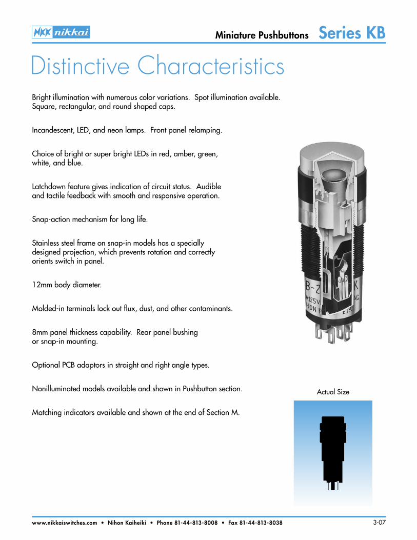
CONTACT MATERIALS, RATINGS & TERMINALS
Silver Contacts
Gold Contacts
Complete explanation of operating range in Supplement section.
W
G
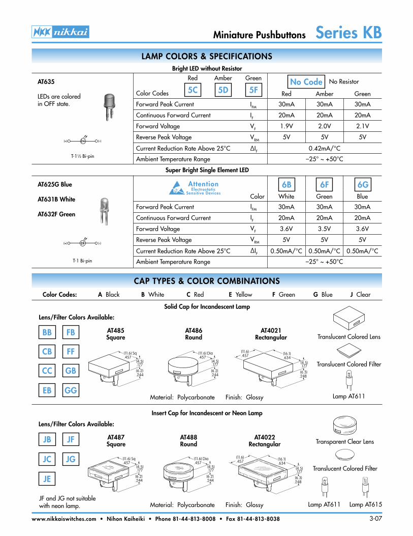
LAMP COLORS & SPECIFICATIONS
The electrical specifications shown are determined at a basic temperature of 25°C. LED circuit is isolated and requires external power source. Polarity marks are on the bottom of the switch.
If the source voltage exceeds the rated voltage, a ballast resistor is required. The resistor value can be calculated by using the formula in the Supplement section.
Ambient Temperature Range for lamps below: –25°C ~ +50°C.
Power Level 1A @ 125V AC & 250V AC
Logic Level 0.4VA maximum @ 28V AC/DC
01 Solder Lug(5.0).197
(1.8).071 (1.0)
.039
(2.0).079
Thk = (0.2) .008
Com = (0.1) .005
A partitioned plastic guard is supplied with each switch to provide insulation between terminals. Installation steps:
1. Identify wire-to-terminal connections. 3. Solder the connections. 2. Thread wires through the guard. 4. Push the guard fully onto the switch body.
(17.0).669
(14.0) Dia .551
(12.4) Dia.488
Voltage V 5V AC 12V AC 110V AC
Current I 115mA 60mA 1.5mA
Endurance Hours 7,000 average 10,000
05 12 01Recommended Resistorsfor Neon: 33K ohms for 110V AC;100K ohms for 220V AC
T-1 Bi-pin
AT611Incandescent
AT615Neon
Incandescent & Neon Lamps
Resistor Codes
Color Codes:
Forward Peak Current IFM — — —
Continuous Forward Current IF 25mA 20mA 10mA
Forward Voltage VF 5V 12V 24V
Reverse Peak Voltage VRM 4V 8V 16V
Current Reduction Rate Above 25°C ∆IF — — —
5C 5D 5F 12 2405
Red Amber GreenAT634
LEDs are colored in OFF state.
T-11⁄4 Bi-pin
Bright LED with Resistor
(-)(+) (+) (-)
(+)
(-)
AT6345-volt2-elementwith 1 Resistor
AT63412-volt4-elementwith 2 Resistors
AT63424-volt4-elementwith 2 Resistors
BARRIER TYPE
No Code No Barrier
Built-in bezel
B With Barrier
Built-in barrier only available for square and rectangular
Miniature Pushbuttons Series KB
www.nikkaiswitches.com • Nihon Kaiheiki • Phone 81-44-813-8008 • Fax 81-44-813-8038 3-07
LAMP COLORS & SPECIFICATIONS
Color White Green Blue
Forward Peak Current IFM 30mA 30mA 30mA
Continuous Forward Current IF 20mA 20mA 20mA
Forward Voltage VF 3.6V 3.5V 3.6V
Reverse Peak Voltage VRM 5V 5V 5V
Current Reduction Rate Above 25°C ∆IF 0.50mA/°C 0.50mA/°C 0.50mA/°C
Ambient Temperature Range –25° ~ +50°C
6F 6G6BAT625G Blue
AT631B White
AT632F Green
T-1 Bi-pin
Super Bright Single Element LED
AttentionElectrostatic
Sensitive Devices
(+) (-)
CAP TYPES & COLOR COMBINATIONS
BB
Solid Cap for Incandescent Lamp
Lens/Filter Colors Available:
CB
CC
EB
AT485 Square
JF and JG not suitablewith neon lamp.
FB
FF
GB
GG
Color Codes: A Black B White C Red E Yellow F Green G Blue J Clear
Material: Polycarbonate Finish: Glossy
AT486 Round
AT4021 Rectangular
Material: Polycarbonate Finish: Glossy
(11.6) Sq.457
(6.2).244
(4.5).177
(11.6) Dia.457
(6.2).244
(4.5).177
(11.6) Sq.457
(6.2).244
(4.5).177
(11.6) Dia.457
(6.2).244
(4.5).177
AT487 Square
AT488 Round
AT4022 Rectangular
Insert Cap for Incandescent or Neon Lamp
JB
JC
JE
JF
JG
Lens/Filter Colors Available:
(6.3).248
(4.5).177
(16.1).634
(11.6).457
(11.6).457
(6.3).248
(4.5).177
(16.1).634
Translucent Colored Lens
Translucent Colored Filter
Lamp AT611
Transparent Clear Lens
Translucent Colored Filter
Lamp AT611 Lamp AT615
Color Codes Red Amber Green
Forward Peak Current IFM 30mA 30mA 30mA
Continuous Forward Current IF 20mA 20mA 20mA
Forward Voltage VF 1.9V 2.0V 2.1V
Reverse Peak Voltage VRM 5V 5V 5V
Current Reduction Rate Above 25°C ∆IF 0.42mA/°C
Ambient Temperature Range –25° ~ +50°C
5C 5D 5FNo CodeRed Amber Green No Resistor
(+) (-)
T-11⁄2 Bi-pin
AT635
LEDs are colored in OFF state.
Bright LED without Resistor

Miniature Pushbuttons Series KB
www.nikkaiswitches.com • Nihon Kaiheiki • Phone 81-44-813-8008 • Fax 81-44-813-8038 3-07
Cap for Bright LED without Resistor or LED with Resistor
Lens/Diffuser Colors Available: (AT4133, 4132, 4134 white diffusers; AT4158, 4160, 4159 colored diffusers)
Square
Material: Polycarbonate Finish: Glossy
Round Rectangular
Material: Polycarbonate Finish: Glossy
(11.6) Sq.457
(6.2).244
(4.5).177
(11.6) Dia.457
(6.2).244
(4.5).177
AT4133 Square
AT4132Round
AT4134Rectangular
Cap for Super Bright LED
JB
Lens/Diffuser Colors Available:
(11.6).457
(6.3).248
(4.5).177
(16.1).634
Transparent Clear Lens
Translucent Diffuser
Translucent Clear Lens
Translucent White Diffuser
CAP TYPES & COLOR COMBINATIONSColor Codes: A Black B White C Red D Amber E Yellow F Green G Blue J Clear
Spot Illuminated Cap for Bright LED without Resistor or with Resistor
Opaque Black Cap with Translucent White Windowfor Spot Illumination
AB
Cap/Window Colors Available:
AT4051 Square
Material: Polycarbonate Finish: MatteBright LED
AT635Bright LED
AT634
(3.0).118
(1.8).071
(5.0).197
(11.6) Sq.457
(4.6).181
(6.2).244
JB
JC
JD
JF
AT4133 AT4132 AT4134
AT4158 AT4160 AT4159
Bright LEDAT635
Bright LEDAT634
(11.6).457
(6.3).248
(4.5).177
(16.1).634
(11.6) Dia.457
(6.2).244
(4.5).177
(11.6) Sq.457
(6.2).244
(4.5).177
Super Bright LEDsAT625
AT631 AT632
Miniature Pushbuttons Series KB
www.nikkaiswitches.com • Nihon Kaiheiki • Phone 81-44-813-8008 • Fax 81-44-813-8038 3-07
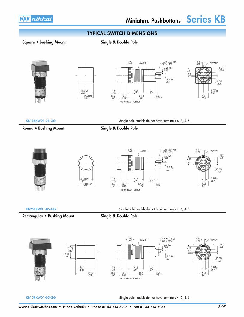
TYPICAL SWITCH DIMENSIONS
Square • Bushing Mount Single & Double Pole
Rectangular • Bushing Mount Single & Double Pole
Round • Bushing Mount Single & Double Pole
KB15SKW01-05-GG Single pole models do not have terminals 4, 5, & 6.
KB25CKW01-05-GG Single pole models do not have terminals 4, 5, & 6.
KB15RKW01-05-GG Single pole models do not have terminals 4, 5, & 6.
(11.6) Sq.457
(14.0) Sq.551
(5.0).197
(1.0).039
(14.2).559
(24.7).972
(5.3).209
(5.0).197
M12 P1 (1.0) x (2.0) Typ.039 x .079
(0.2) Typ.008
(1.8) Typ.071
(3.5).138
Latchdown Position
(1.4).055
6 3
5 2
14L LCOM
(4.9).193
(1.8).071
Keyway
(.127).005
(5.08) .200
(9.0).354
(1.7) Typ.067
(11.6) Dia.457
(14.0) Dia.551
(5.0).197
(1.0).039
(14.2).559
(24.7).972
(5.3).209
(5.0).197
M12 P1 (1.0) x (2.0) Typ.039 x .079
(0.2) Typ.008
(1.8) Typ.071
(3.5).138
Latchdown Position
(1.4).055
6 3
5 2
14L LCOM
(4.9).193
(1.8).071
Keyway
(.127).005
(5.08) .200
(9.0).354
(1.7) Typ.067
(11.6).457
(16.1).634
(18.5).728
(14.0).551
(5.0).197
(1.0).039
(14.2).559
(24.7).972
(5.3).209
(3.5).138
(5.0).197
M12 P1 (1.0) x (2.0) Typ.039 x .079
(0.2) Typ.008
(1.8) Typ.071
Latchdown Position
(1.4).055
6 3
5 2
14L LCOM
(4.9).193
(1.8).071
Keyway
(.127).005
(5.08) .200
(9.0).354
(1.7) Typ.067
Miniature Pushbuttons Series KB
www.nikkaiswitches.com • Nihon Kaiheiki • Phone 81-44-813-8008 • Fax 81-44-813-8038 3-07
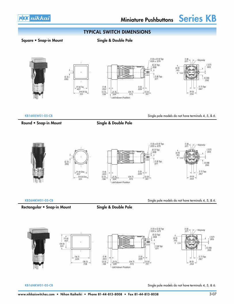
TYPICAL SWITCH DIMENSIONS
Square • Snap-in Mount Single & Double Pole
Rectangular • Snap-in Mount Single & Double Pole
Round • Snap-in Mount Single & Double Pole
KB16KKW01-05-CB Single pole models do not have terminals 4, 5, & 6.
KB26MKW01-05-CB Single pole models do not have terminals 4, 5, & 6.
KB16NKW01-05-CB Single pole models do not have terminals 4, 5, & 6.
(2.3).090
(11.6) Sq.457
(14.0) Sq.551
(1.0).039
(24.7).972
(5.3).209
(5.0).197
(1.0) x (2.0) Typ.039 x .079
(0.2) Typ.008
(1.8) Typ.071
(3.5).138
Latchdown Position
(1.4).055
6 3
5 2
14L LCOM
(4.9).193
(1.8).071
Keyway
(.127).005
(5.08) .200
(9.0).354
(1.7) Typ.067
6 3
5 2
14L LCOM
(4.9).193
(1.8).071
Keyway
(.127).005
(5.08) .200
(9.0).354
(1.7) Typ.067
(1.0).039
(24.7).972
(5.3).209
(5.0).197
(1.0) x (2.0) Typ.039 x .079
(0.2) Typ.008
(1.8) Typ.071
(3.5).138
Latchdown Position
(1.4).055
(11.6) Dia.457
(14.0) Dia.551
(2.3).090
(11.6).457
(16.1).634
(18.5).728
(14.0).551
(1.0).039
(24.7).972
(5.3).209
(5.0).197
(1.0) x (2.0) Typ.039 x .079
(0.2) Typ.008
(1.8) Typ.071
(3.5).138
Latchdown Position
(1.4).055
6 3
5 2
14L LCOM
(4.9).193
(1.8).071 Keyway
(.127).005
(5.08) .200
(9.0).354
(1.7) Typ.067
Miniature Pushbuttons Series KB
www.nikkaiswitches.com • Nihon Kaiheiki • Phone 81-44-813-8008 • Fax 81-44-813-8038 3-07
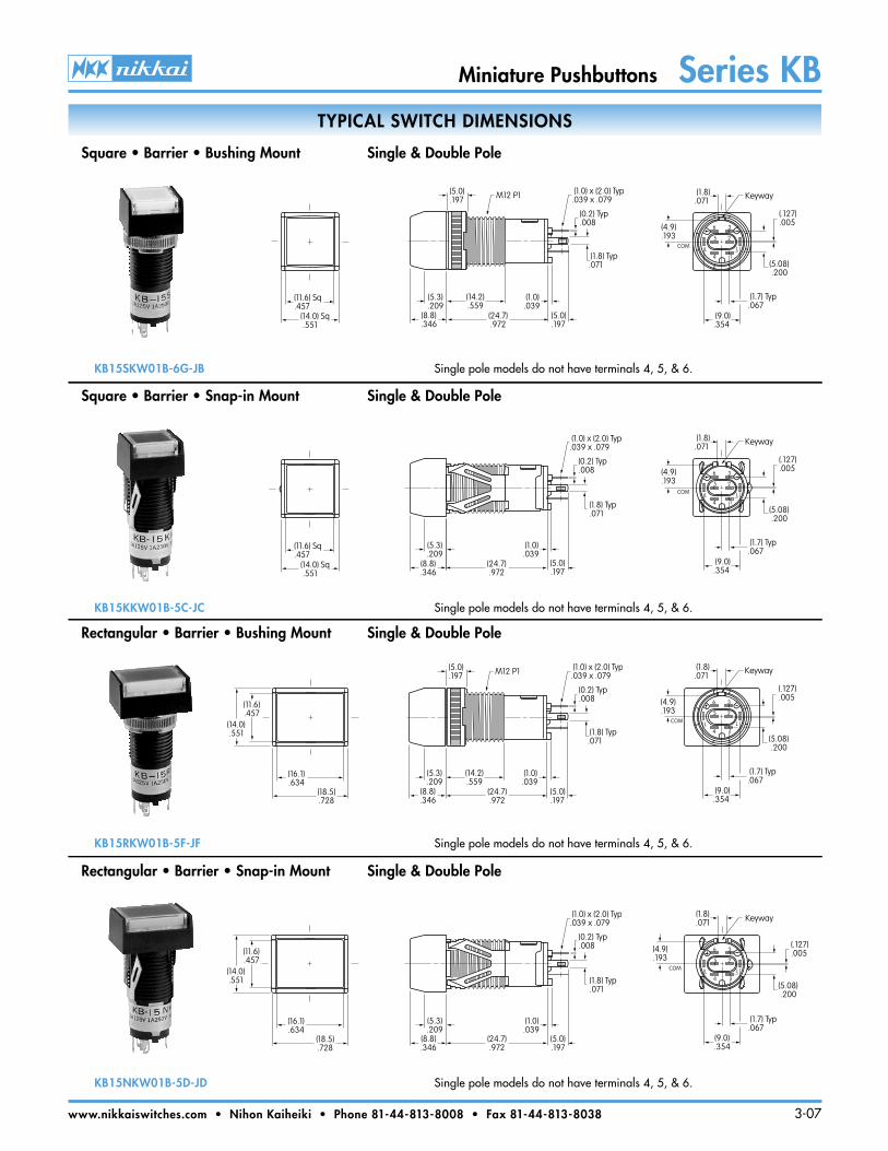
TYPICAL SWITCH DIMENSIONS
Square • Barrier • Bushing Mount Single & Double Pole
Rectangular • Barrier • Bushing Mount Single & Double Pole
Square • Barrier • Snap-in Mount Single & Double Pole
KB15SKW01B-6G-JB Single pole models do not have terminals 4, 5, & 6.
KB15KKW01B-5C-JC Single pole models do not have terminals 4, 5, & 6.
KB15RKW01B-5F-JF Single pole models do not have terminals 4, 5, & 6.
6 3
5 2
14L LCOM
(4.9).193
(1.8).071
Keyway
(.127).005
(5.08) .200
(9.0).354
(1.7) Typ.067
6 3
5 2
14L LCOM
(4.9).193
(1.8).071
Keyway
(.127).005
(5.08) .200
(9.0).354
(1.7) Typ.067
6 3
5 2
14L LCOM
(4.9).193
(1.8).071
Keyway
(.127).005
(5.08) .200
(9.0).354
(1.7) Typ.067
6 3
5 2
14L LCOM
(4.9).193
(1.8).071 Keyway
(.127).005
(5.08) .200
(9.0).354
(1.7) Typ.067
Rectangular • Barrier • Snap-in Mount Single & Double Pole
KB15NKW01B-5D-JD Single pole models do not have terminals 4, 5, & 6.
(5.0).197
(1.0).039
(14.2).559
(24.7).972
(5.3).209
(5.0).197
M12 P1 (1.0) x (2.0) Typ.039 x .079
(0.2) Typ.008
(1.8) Typ.071
(8.8).346
(11.6) Sq.457
(14.0) Sq .551
(11.6) Sq.457
(14.0) Sq .551
(1.0).039
(24.7).972
(5.0).197
(1.0) x (2.0) Typ.039 x .079
(0.2) Typ.008
(1.8) Typ.071
(5.3).209
(8.8).346
(11.6).457
(16.1).634
(18.5).728
(14.0).551
(5.0).197
(1.0).039
(14.2).559
(24.7).972
(5.3).209
(5.0).197
M12 P1 (1.0) x (2.0) Typ.039 x .079
(0.2) Typ.008
(1.8) Typ.071
(8.8).346
(11.6).457
(16.1).634
(18.5).728
(14.0).551
(1.0).039
(24.7).972
(5.0).197
(1.0) x (2.0) Typ.039 x .079
(0.2) Typ.008
(1.8) Typ.071
(5.3).209
(8.8).346
Miniature Pushbuttons Series KB
www.nikkaiswitches.com • Nihon Kaiheiki • Phone 81-44-813-8008 • Fax 81-44-813-8038 3-07
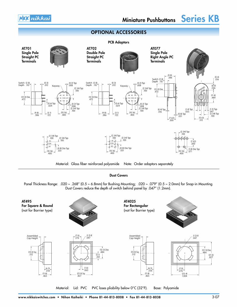
OPTIONAL ACCESSORIES
PCB Adaptors
Dust Covers
AT701Single Pole Straight PC Terminals
AT702Double Pole Straight PC Terminals
AT077Single Pole Right Angle PC Terminals
Material: Glass fiber reinforced polyamide Note: Order adaptors separately
+ -6
5
4 1
2
3NC
COM
NO
(0.2) Typ.008(2.54) Typ .100
(10.16) .400
(2.54) Typ .100
(0.2) Typ.008Keyway
(12.0) Dia.472
SwitchDepth
(2.8).110
(0.3).012
(9.8).386
(3.1).122
(0.6) Typ.024
+ -6
5
4 1
2
3NC
COM
NO
(0.2) Typ.008(2.54) Typ .100
(10.16) .400
(2.54) Typ .100
(0.2) Typ.008Keyway
(12.0) Dia.472
SwitchDepth
(2.8).110
(0.3).012
(9.8).386
(3.1).122
(0.6) Typ.024
+ -
3 2 1
(11.4).449
(6.0).236
(1.4) Typ.055
(13.0).512
(2.54) Typ .100
(1.2) Typ.047
(0.4).016
(7.62).300
(0.8) Typ.031
(0.4) Typ.016
(12.0) Dia.472
(9.8).386
SwitchDepth
(2.8).110
3 NC
1
2 COM
(2.54) Typ .100 (2.54) Typ
.100
(0.8) Dia Typ.031(10.16)
.400
NO
3 NC
1
2 COM
(2.54) Typ .100 (2.54) Typ
.100
(0.8) Dia Typ.031(10.16)
.400
NO
6
5
4
1 2 3
(2.54) Typ .100
(7.62).300
(1.8) Dia Typ.071(10.16)
.400
Material: Lid: PVC PVC loses pliability below 0°C (32°F). Base: Polyamide
Panel Thickness Range: .020 ~ .268” (0.5 ~ 6.8mm) for Bushing Mounting; .020 ~ .079” (0.5 ~ 2.0mm) for Snap-in MountingDust Covers reduce the depth of switch behind panel by .047” (1.2mm).
AT495For Square & Round(not for Barrier type)
AT4025For Rectangular(not for Barrier type)
(12.3) Dia.484
(5.1).201
(21.0) Sq.827
(7.0).276
(1.2) R.047
(1.6).063
(25.4)1.004
(1.2) R.047
(21.0).827
(12.3) Dia.484
(7.0).276
(11.8).465
AssembledCap Height
(13.0) Sq .512
(6.5).256
AssembledCap Height
(13.0) Sq .512
(6.5).256
(11.8).465
Miniature Pushbuttons Series KB
www.nikkaiswitches.com • Nihon Kaiheiki • Phone 81-44-813-8008 • Fax 81-44-813-8038 3-07
Indentation
Long Tab
NotchSlot
Round Tab
Cap
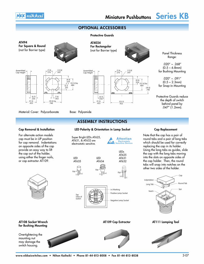
OPTIONAL ACCESSORIES
Protective Guards
AT494For Square & Round(not for Barrier type)
Material: Cover: Polycarbonate Base: Polyamide
AT4024For Rectangular(not for Barrier type)
ASSEMBLY INSTRUCTIONS
Panel Thickness Range:
.020” ~ .268” (0.5 ~ 6.8mm)
for Bushing Mounting
.020” ~ .091” (0.5 ~ 2.3mm)
for Snap-in Mounting
Protective Guards reduce the depth of switch behind panel by.047” (1.2mm).
(6.5).256
(11.5).453
AssembledCap Height
(5.1).201
(12.3) Dia.484
(9.0).354
(19.0) Sq.748
(7.0).276
(1.2) R.047
(1.6).063
(6.5).256
(11.5).453
AssembledCap Height
(23.5).925
(9.0).354
(12.3) Dia.484
(7.0).276
(1.2) R.047
(19.0).748
Cap Removal & Installation
For alternate action models cap must be in UP position for cap removal. Indentations on opposite sides of the cap provide an easy way to lift the cap out of the holder, using either the finger nails, or cap extractor AT109.
LED Polarity & Orientation in Lamp Socket Cap Replacement
Note that the cap has a pair of round tabs and a pair of long tabs which should be used for correctly replacing the cap in its holder. Using the long tabs as guides, slide the cap with the long tabs moving into the slots on opposite sides of the cap holder. Then, the round tabs will snap into notches on the other two sides of the holder.
AT108 Socket Wrench for Bushing Mounting
AT109 Cap Extractor AT111 Lamping Tool
Super Bright LEDs AT625, AT631, & AT632 are electrostatic sensitive.
LEDAT635
LEDsAT625AT631AT632
LEDAT634
Overtightening the mounting nut may damage the switch housing.
Flat
(-) (+)
Flat
(-) (+)
AttentionElectrostatic
Sensitive Devices
(+) Marking
Positive Lamp Socket
Negative Lamp Socket
TopView ofSwitch
Flat
(+)(-)
Miniature Pushbuttons Series KB
www.nikkaiswitches.com • Nihon Kaiheiki • Phone 81-44-813-8008 • Fax 81-44-813-8038 3-07
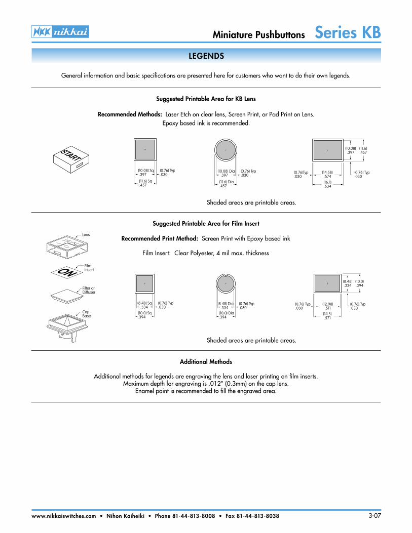
LEGENDS
Shaded areas are printable areas.
Shaded areas are printable areas.
Recommended Print Method: Screen Print with Epoxy based ink
Film Insert: Clear Polyester, 4 mil max. thickness
Additional Methods
Additional methods for legends are engraving the lens and laser printing on film inserts.Maximum depth for engraving is .012” (0.3mm) on the cap lens.
Enamel paint is recommended to fill the engraved area.
Suggested Printable Area for KB Lens
Suggested Printable Area for Film Insert
(10.08) Sq .397
(11.6) Sq.457
(0.76) Typ.030
(10.08) Dia .397
(11.6) Dia.457
(0.76) Typ.030
(14.58).574(16.1).634
(0.76) Typ.030
(10.08).397
(11.6).457
(0.76)Typ.030
(12.98).511
(14.5).571
(0.76) Typ.030
(8.48).334
(10.0).394
(0.76) Typ.030
(8.48) Dia .334(10.0) Dia.394
(0.76) Typ.030
(8.48) Sq .334
(10.0) Sq.394
(0.76) Typ.030
CapBase
Filter orDiffuser
FilmInsert
Lens
ON
START
Recommended Methods: Laser Etch on clear lens, Screen Print, or Pad Print on Lens.Epoxy based ink is recommended.
General information and basic specifications are presented here for customers who want to do their own legends.