Embed Size (px)
Citation preview
255 Glider Circle • Corona, CA 92880(951) 371-1730• FAX (951) 371-2592
www.TrigonElectronics.com
October 28, 2004
INSTALLATIONand
OPERATION INSTRUCTIONS
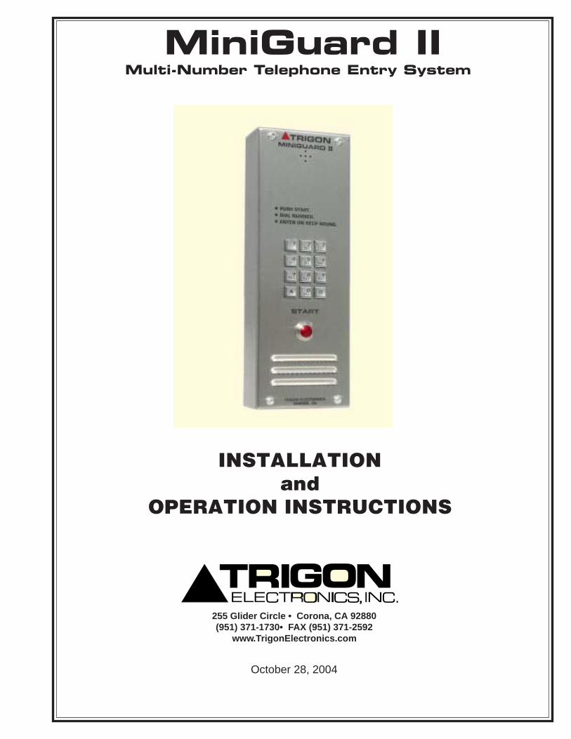
Multi-Number Telephone Entry SystemMiniGuard II
Page 2
Miniguard II
TABLE OF CONTENTSTABLE OF CONTENTSTABLE OF CONTENTSTABLE OF CONTENTSTABLE OF CONTENTSINTRODUCTION ..................................................................................... 3
PRODUCT OVERVIEW .......................................................................... 3
MOUNTING .............................................................................................. 4
WIRING ..................................................................................................... 4
WIRING DIAGRAM ................................................................................ 5
SYSTEM SETUPEnter Program Mode Locally .................................................................. 6Enter program Mode Remotely ............................................................... 6Initial Set-up ............................................................................................ 6 Enter Resident Code length .................................................................. 6 Enter Ring Count .................................................................................. 6 Enter Gate Interval ............................................................................... 6 Enter Call Length ................................................................................. 6 Enter Dial Mode ................................................................................... 6 Enter Latch Enable / Disable ................................................................ 6
PROGRAMMINGProgramming After Set-up ...................................................................... 7Adding Telephone Numbers .................................................................... 7Deleting Telephone Numbers ................................................................... 7Programming Entry Codes ..................................................................... 7Changing the Factory Program Code ....................................................... 7Deleting Entry Codes ............................................................................... 7Entering Access Cards .............................................................................. 8Deleting Cards .......................................................................................... 8Programming Site ID Code ..................................................................... 8Programming Tamper Code .................................................................... 8Programming (Optional) Time-of-Day Clock ......................................... 8Programming Primary Relay "On" time ................................................. 9Programming Secondary Relay "On" time (Option)................................ 9Master Erase ............................................................................................ 9
OPERATIONCalling a Tenant....................................................................................... 10Direct Entry Codes .................................................................................. 10Granting Visitor Entry ............................................................................. 10Denying Visitor Entry ............................................................................. 10Latching/Unlatching Relays .................................................................... 10Site Identification .................................................................................... 10Remote Operation Time-out .................................................................... 11Remote Function Tests ............................................................................ 11Printer Operation (OPTIONAL) ............................................................. 11
TROUBLE SHOOTING ........................................................................... 12
CONDENSED GUIDE TO USE AND PROGRAMMING .................... 12/13
SPECIFICATIONS / FEATURES ............................................................ 14
Revision 111901 Approved
Page 3
Miniguard II
This manual contains the information required to installand program the TRIGON Miniguard II. If you are usingthis manual to install this unit, it is very important toread all the sections in order.
You should read these instructions before you begininstallation. This will insure that everything is doneefficiently.
Hookup Specifications
If you are using this manual as a programming guideafter the initial installation, you may find the TABLEOF CONTENTS useful in locating the particularprogramming procedure you need.
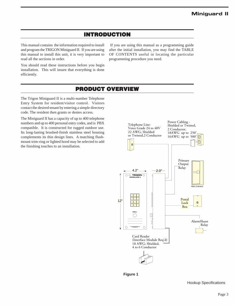
The Trigon Miniguard II is a multi-number TelephoneEntry System for resident/visitor control. Visitorscontact the desired tenant by entering a simple directorycode. The resident then grants or denies access.
The Miniguard II has a capacity of up to 400 telephonenumbers and up to 400 personal entry codes, and is PBXcompatible. It is constructed for rugged outdoor use.Its long-lasting brushed-finish stainless steel housingcomplements its thin design lines. A matching flush-mount trim-ring or lighted hood may be selected to addthe finishing touches to an installation.
PRODUCT OVERVIEWPRODUCT OVERVIEWPRODUCT OVERVIEWPRODUCT OVERVIEWPRODUCT OVERVIEW
INTRODUCTIONINTRODUCTIONINTRODUCTIONINTRODUCTIONINTRODUCTION
TRIGONMINIGUARD II
CALL
TRIGON ELECTRONICS ORANGE CA.
4.2"
12"
Telephone Line-Voice Grade 24 to 48V22 AWG; Shieldedor Twisted,2 Conductor
PostalLockBox
PrimaryOutputRelay
Main Entrance
Power Cabling -Shielded or Twisted,2 Conductor,18AWG up to 250'16AWG up to 500'
Card Reader(Interface Module Req'd)18 AWG; Shielded,4 to 6 Conductor
AlarmShuntRelay
2.0"
Figure 1
Page 4
Miniguard II
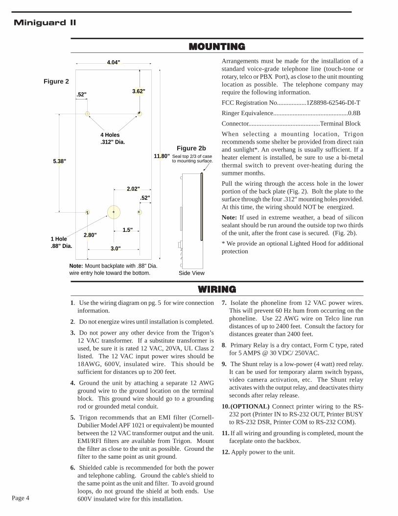
Figure 2
MOUNTINGMOUNTINGMOUNTINGMOUNTINGMOUNTINGArrangements must be made for the installation of astandard voice-grade telephone line (touch-tone orrotary, telco or PBX Port), as close to the unit mountinglocation as possible. The telephone company mayrequire the following information.
FCC Registration No..................1Z8898-62546-DI-T
Ringer Equivalence..............................................0.8B
Connector............................................Terminal Block
When selecting a mounting location, Trigonrecommends some shelter be provided from direct rainand sunlight*. An overhang is usually sufficient. If aheater element is installed, be sure to use a bi-metalthermal switch to prevent over-heating during thesummer months.
Pull the wiring through the access hole in the lowerportion of the back plate (Fig. 2). Bolt the plate to thesurface through the four .312" mounting holes provided.At this time, the wiring should NOT be energized.
Note: If used in extreme weather, a bead of siliconsealant should be run around the outside top two thirdsof the unit, after the front case is secured. (Fig. 2b).
* We provide an optional Lighted Hood for additionalprotection
.52" 3.62"
+
+
4.04"
11.80"5.38"
2.80"
++
3.0"
.52"
1.5"
2.02"
1 Hole.88" Dia.
4 Holes.312" Dia.
Note: Mount backplate with .88" Dia.wire entry hole toward the bottom.
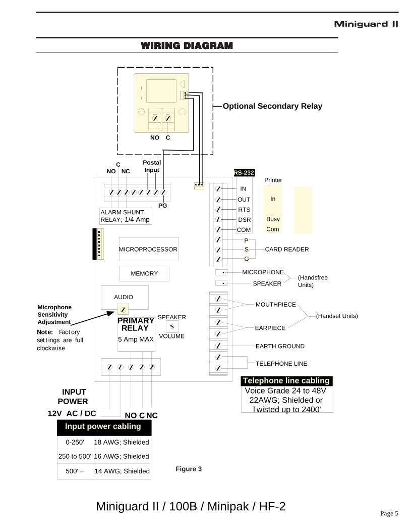
WIRINGWIRINGWIRINGWIRINGWIRING1. Use the wiring diagram on pg. 5 for wire connection
information.
2. Do not energize wires until installation is completed.
3. Do not power any other device from the Trigon’s12 VAC transformer. If a substitute transformer isused, be sure it is rated 12 VAC, 20VA, UL Class 2listed. The 12 VAC input power wires should be18AWG, 600V, insulated wire. This should besufficient for distances up to 200 feet.
4. Ground the unit by attaching a separate 12 AWGground wire to the ground location on the terminalblock. This ground wire should go to a groundingrod or grounded metal conduit.
5. Trigon recommends that an EMI filter (Cornell-Dubilier Model APF 1021 or equivalent) be mountedbetween the 12 VAC transformer output and the unit.EMI/RFI filters are available from Trigon. Mountthe filter as close to the unit as possible. Ground thefilter to the same point as unit ground.
6. Shielded cable is recommended for both the powerand telephone cabling. Ground the cable's shield tothe same point as the unit and filter. To avoid groundloops, do not ground the shield at both ends. Use600V insulated wire for this installation.
7. Isolate the phoneline from 12 VAC power wires.This will prevent 60 Hz hum from occurring on thephoneline. Use 22 AWG wire on Telco line rundistances of up to 2400 feet. Consult the factory fordistances greater than 2400 feet.
8. Primary Relay is a dry contact, Form C type, ratedfor 5 AMPS @ 30 VDC/ 250VAC.
9. The Shunt relay is a low-power (4 watt) reed relay.It can be used for temporary alarm switch bypass,video camera activation, etc. The Shunt relayactivates with the output relay, and deactivates thirtyseconds after relay release.
10.(OPTIONAL) Connect printer wiring to the RS-232 port (Printer IN to RS-232 OUT, Printer BUSYto RS-232 DSR, Printer COM to RS-232 COM).
11. If all wiring and grounding is completed, mount thefaceplate onto the backbox.
12. Apply power to the unit.
Figure 2b
Seal top 2/3 of case to mounting surface.
Side View
Figure 2b
Page 5
Miniguard II
WIRING DIAGRAMWIRING DIAGRAMWIRING DIAGRAMWIRING DIAGRAMWIRING DIAGRAM
0-250'
500' +
18 AWG; Shielded
16 AWG; Shielded
14 AWG; Shielded
Input power cabling
250 to 500'
ALARM SHUNT
IN
OUT
DSR
COM
RS-232
CARD READER
EARTH GROUND
TELEPHONE LINE
MICROPROCESSOR
AUDIO
SPEAKER
VOLUME
PRIMARYRELAY
12V AC / DC NO C NC
RELAY;
INPUTPOWER
5 Amp MAX
1/4 Amp
NC
MEMORY
P
S
G
CNO
Telephone line cablingVoice Grade 24 to 48V 22AWG; Shielded or Twisted up to 2400'
Busy
Com
Printer
In
RTS
MicrophoneSensitivityAdjustment
PG
EARPIECE
MOUTHPIECE
(HandsfreeUnits)
MICROPHONE
SPEAKER
(Handset Units)
Note: Fact oryset t ings are fullclockw ise
Postal Input
Miniguard II / 100B / Minipak / HF-2
NO C
Optional Secondary Relay
Figure 3
Page 6
Miniguard II
For example: Enter “1” for one 5-second interval. Enter“2” for two 5-second intervals (10 seconds). Enter “6”for six 5-second intervals (30 seconds) etc.
Note: Nine is the maximum..
5. Enter the number of 5-second intervalsdesired. ( ) [ 3 ]
Note: A “0” here will allow the output relay to engagefor a one second pulse
Enter Call Length:
“Call Length” refers to the maximum time (in minutes)that the unit will allow a conversation to last.
6. Enter the number (1 thru 4) that corresponds tothe call length time (in minutes) that isdesired. ( ) [ 3 ]
Note: A “0” here allows indefinite call length, howeverthe unit will auto disconnect after 30 seconds of voicesilence.
Enter Dial Mode:“Dial Mode” refers to the type of signal the unit uses todial a telephone number. The Miniguard II is capableof dialing rotary/pulse or touch-tone.
Enter “0” if touch-tone is desired.Enter “1” for rotary.Enter "2" for Touch-tone dialout and active DTMF keypad after dialout.Enter "3" for Rotary dialout and active DTMFkeypad after dialout.7. Enter dial mode desired ( ) [ 0 ].
Note: Adding TWO to the Dial Mode selection allowsthe keypad of the Miniguard II to remain active for usewith voice-mail/automated attendant systems, after theinitial call is placed and answered.
Enter Latch Enable/Disable:
“Latch Enable/Disable” refers to the ability of theMiniguard II to latch (hold closed) the #1 relay, from aremote location.
Enter " 1 " to enable the latch feature for relay #1. Enter" 0 " to disable this feature.8. Enter latch mode desired ( ) [ 0 ].
You will hear two beeps. . . .setup complete.
9. Enter "# #" to exit Program Mode, otherwise,continue programming by entering the desiredfunction code.
.
SYSTEM SETUPSYSTEM SETUPSYSTEM SETUPSYSTEM SETUPSYSTEM SETUP
General Programming Information:The "Initial Setup" for the Miniguard II has beenprogrammed at the factory. These factory default settingsmay be changed to better suit your particular application.If you decide to alter these settings, follow theinstructions below. It is important that each programmingstep be taken in order. When reprogramming a specificfeature, you must always enter the programming modefirst. You may then go to the appropriate procedural stepsfor the changes desired.
Note: It is recommended that you read thru all of thefollowing sections first, before any change is attempted.This will familiarize you with the procedure required.Record any programmed information you wish to changein the spaces ( ) provided. Factory default is displayedin brackets [ ].
(A) To Enter Program Mode Locally:
1. Press button for dialtone.2. Enter " ✽ " then enter the unit’s Program Code.
If the unit is new, use the preset factory code. (Factorycode is 5269). You will hear two beeps
-OR-
(B) To Enter Program Mode Remotely:
1. Call the telephone number of the unit.2. Listen for a single tone.3. Enter " ✽ " then the unit's Program Code.
If the unit is new, use the preset factory code. (Factorycode is 5269). You will hear two beeps
(C) To Run Initial Setup:
1. Unit must be in programming mode (see above).2. Enter "#, 0". This tells the unit that you want torun SETUP. No beeps will be heard.
Enter Resident Code Length: This will be the number visible on the directory used bya visitor to locate a resident.
Note: Resident codes may be from 1 to 4 digits in length.All resident codes must be of the same length.
3. Enter the resident code length. 1 for one digit, 2for two digits etc.( ) [ 3 ]
Enter Ring Count:“Ring Count” refers to the number of incoming ringsthe Miniguard II will wait before it auto-answers. Thiscount is adjustable from 1 to 9.
4. Enter the number that indicates the number ofrings desired. ( ) [ 3 ]
Enter Gate Interval:"Gate Interval" refers to the length of time the outputrelay (parking gate, front entry, etc.) will stay engagedafter the command has been issued.
Page 7
Miniguard II
PROGRAMMINGPROGRAMMINGPROGRAMMINGPROGRAMMINGPROGRAMMING
(A) Programming after Set-up:In order to program the unit, it must be in the ProgramMode. If you came from SETUP and didn’t exit or reset,go on to (B), "Adding Telephone Numbers”. Otherwise:
1. Press button for dial tone and enter " ✽ "2. Enter the Program Code (5269 if unit is new).
You will hear two beeps. The unit is now ready toprogram.
(B) Adding Telephone Numbers:
1. Unit must be in Program Mode (see section A).2. Enter Resident Code that you wish to file thetelephone number under. (The number will be setfrom 1 to 4 digits in length.)
You will hear one beep when you have entered thecorrect number of digits.
3. Enter the telephone number. (The telephonenumber can be up to twelve digits in length.)
4. Press "#" to complete the entry.You will hear two beeps. Three beeps indicates memoryfull.
Repeat the above steps until you are finished.
5. Enter "# #" to exit Program Mode, otherwise,continue programming by entering the desiredfunction code.
(C) Deleting Telephone Numbers:
1. Unit must be in Program Mode (see section A).2. Enter the Resident Code you wish to delete.
You will hear one beep.
3. Enter "#" .Two beeps indicate Erasure complete.
Repeat steps 2 and 3 until you are finished.
4. Enter "# #" to exit Program Mode, otherwise,continue programming by entering the desiredfunction code.
Note: If you wish to change a telephone number underan existing Resident Code, use the instructions forAdding Telephone Numbers and enter the new numberin place of the old one. The old number will beoverwritten.
(D) Programming Entry Codes:Entry Codes make it possible for the resident to enter aCode (P.I.N. number) at the unit and gain access withoutplacing a call.
1. Unit must be in Program Mode (see section A).2. Enter "# 1".3. Enter any 4-digit number between 0000 and8999.
You will hear two beeps, indicating the number has beenrecorded in the Miniguard II’s memory.
Repeat steps 2 and 3 until you are finished.
Note: Three beeps indicate the code already existed.
4. Enter "# #" to exit Program Mode, otherwise,continue programming by entering the desiredfunction code.
(E) Changing the Program Code:This feature allows you to change the Program Code tosomething other than the factory preset of 5269.
1. Unit must be in Program Mode (see section A).2. Enter "# 7"3. Enter 4 digits for new Program Code.You will hear two beeps.4. Enter "# #" to exit Program Mode, otherwise,continue programming by entering the desiredfunction code.
Note: The 5269 Code (or any other previous code) isnow invalid, so keep a good, safe record of your newProgram Code for future use.
Note: If you lose the ability to access the Program Modeafter performing this step, call TRIGON service. Wehave the ability to remotely reset the Program Code backto default.
(F) Deleting Entry Codes:
1. Unit must be in Program Mode (see section A).2. Enter "# 2"3. Enter the Entry Code that you want to delete.
You will hear two beeps. Erasure complete.
Three beeps indicate no Code match found.
4. Enter "# #" to exit Program Mode, otherwise,continue programming by entering the desiredfunction code.
Page 8
Miniguard II
(G) Entering Access Cards:This function requires the installation of the Card ReaderInterface option and a card reader. Card access makes itpossible for the user to use an access card at the unit andgain entry. Each card entered is converted to a standard4 digit Entry Code and goes into “Keyless Entry Codememory”.
1. Unit must be in Program Mode (see section A).2. Enter “# 1”. (You are in 'Batch Mode).3. Pass a card through the card reader.
You will hear one beep.
This indicates card number accepted. Three 'beeps'indicates card not accepted.
For next card repeat step 3 until all cards have beenentered .
Note: If 3 beeps are heard, that card cannot be usedbecause it already appears in memory. Batch Mode isterminated on this or any fault.
4. Enter “#” when card programming is complete,to return to main Program Mode.5. Enter "# #" to exit Program Mode, otherwise,continue programming by entering the desiredfunction code.
(H) Deleting Cards:
If the 4 digit value assigned to the card is known, it canbe removed from memory with the same procedure asDeleting Entry Codes. Otherwise, from Program Mode:
1. Unit must be in Program Mode (see section A).2. Enter “#2” and pass the card to be deletedthrough the reader.
You will hear one beep.
This indicates successful removal.
Note: Three beeps indicates that the card was not inmemory, and the Batch Mode is aborted.
3. Enter “#2” to re-enter Batch Mode.
- or -
If the card has been successfully removed
4. Enter “#” to return to normal Program Modethen, continue programming by entering thedesired function code.5. Enter "# #" to exit Program Mode, otherwise,continue programming by entering the desiredfunction code.
(I) Programming Site Identification Code:In the case of multi-unit installations, the SiteIdentification Code makes it possible for the partyreceiving a call from a Miniguard II to identify which“gate” is calling.
1. Unit must be in Program Mode (see section A).2. Enter "# 8" and the 4 digit number.
You will hear two beeps.
3. Enter "# #" to exit Program Mode, otherwise,continue programming by entering the desiredfunction code.
(J) Programming Tamper Code:This feature can be used to alert a manager if the unit isbeing tampered with. (Four unsuccessful or invalidattempts to enter the programming mode constitutes atamper.) The unit looks up the Resident Code stored in“tamper” and dials the phone number associated with
that resident code.
1. Unit must be in Program Mode (see section A).2. Enter " # 6" and the Resident Code that youhave chosen.
You will hear two beeps.
3. Enter "# #" to exit Program Mode, otherwise,continue programming by entering the desiredfunction code.
(K) Programming Time-of-Day Clock (Optional):The time of day clock option allows automatic operationof the output relay.
1. Unit must be in Program Mode (see section A).2. Enter " # 3 " .3. Enter the Month. (01=Jan., 02=Feb.,... 12=Dec). Be sure to include the zeros when setting theclock.
4. Enter the Monthly Date. (01 thru 31).5. Enter the last two digits of the Year.6. Enter the Hour. Use military time; 00 thru 23 hrs.
7. Enter the Minutes. (00 thru 59).8. Enter the Day of Week. (1= Mon., 2=Tues, ...7=Sun.).
You should will hear two beeps.
Note: Military time format (24 hour clock) is used inclock programming .
9. Enter "# #" to exit Program Mode, otherwise,continue programming by entering the desiredfunction code.
PROGRAMMING, ContinuedPROGRAMMING, ContinuedPROGRAMMING, ContinuedPROGRAMMING, ContinuedPROGRAMMING, Continued
Page 9
Miniguard II
You will hear two beeps.
Note: Day entries must be 2 digits (start and end day).
Note: To program the relay to operate only one day aweek, enter the digit for that day twice (“6 6” meansSaturday only).
6. Enter "# #" to exit Program Mode, otherwise,continue programming by entering the desiredfunction code.
(N) Master Erase:This procedure allows selective or complete deletion ofall data in the Miniguard II’s memory. Also, it is possibleto reset the Miniguard II back to its factory defaults(presets).
Note: Use caution when performing these steps.
1.Unit must be in Program Mode(see section A),2. Enter " # ✽ ".3. Enter "0" if you wish to erase all data and resetunit back to factory defaults.4. Enter "1" if you wish to erase all Entry Codesonly.5. Enter "2" if you wish to erase all Resident Code/telephone numbers only.6. Enter "3" if you wish to reset the unit back tofactory defaults, leaving all other memory intact.
Upon completion of the full master erase sequence, youwill hear a long series of beeps.
Note: Master Erase time will vary greatly depending onmemory type, usage and capacity.
7. Enter "# #" to exit Program Mode, otherwise,continue programming by entering the desiredfunction code.
(L) Programming Primary Relay on/off schedule:This feature allows time clock control of Primary Relay.You may set the relay to activate at a certain time ofday and deactivate at a later time of the same day. Also,you may set this daily on\off action to happen within acertain part of the week; i.e. Tuesday through Friday.
Note: (TIME Clock Option required) Military timeformat (24 hour clock) is used in clock programming.
To program Primary Relay, do the following:
1. Unit must be in Program Mode (see section A).2. Enter "# 4"3. Enter Start Time (Use military format ofhours:minutes, i.e. “0600” , “1500”). Entry must befour digits.
4. Enter End Time (same four digit format as above).5. Enter Start Day and End Day ("1 thru 7" meansMonday through Sunday). For example, entering 24would set the clock for Tuesday through Thursday.
You will hear two beeps.
Note: Day entries must be 2 digits (start and end day).
Note: To program the relay to operate only one day aweek, enter the digit for that day twice (“6 6” meansSaturday only).
6. Enter "# #" to exit Program Mode, otherwise,continue programming by entering the desiredfunction code.
(M) (Requires Time Clock Option)
Programming Secondary Relay on/off schedule:This feature allows time clock control of optionalSecondary Relay. You may set the relay to activate at acertain time of day and deactivate at a later time of thesame day. Also, you may set this daily on\off action tohappen within a certain part of the week; i.e. Tuesdaythrough Friday.
Note: Military time format (24 hour clock) is used inclock programming .
To program Secondary Relay, do the following:
1. Unit must be in Program Mode (see section A).2. Enter "# 5"3. Enter Start Time (Use military format ofhours:minutes, i.e. “0600” , “1500”). Entry must befour digits.
4. Enter End Time (same four digit format as above).5. Enter start day and End Day ("1 thru 7" meansMonday through Sunday). For example, entering 24would set the clock for Tuesday through Thursday.
PROGRAMMING, ContinuedPROGRAMMING, ContinuedPROGRAMMING, ContinuedPROGRAMMING, ContinuedPROGRAMMING, Continued
Page 10
Miniguard II
OPERATIONOPERATIONOPERATIONOPERATIONOPERATION
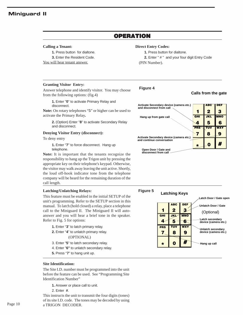
Direct Entry Codes:1. Press button for dialtone.2. Enter " # " and your four digit Entry Code
(PIN Number).
1 2ABC
3DEF
4GHI
5JKL
6MNO
7PRS
8TUV
9WXY
* 0 #Open Door / Gate anddisconnect from call
Activate Secondary device (camera etc.)and disconnect from call
Activate Secondary device (camera etc.)and continue conversation
Hang up from gate call
Calls from the gateFigure 4
1 2ABC
3DEF
4GHI
5JKL
6MNO
7PRS
8TUV
9WXY
* 0 #
Latching KeysLatch Door / Gate open
Unlatch Door / Gate
Latch secondarydevice (camera etc.)
Unlatch secondarydevice (camera etc.)
Hang up call
(Optional)
Figure 5
Site Identification:The Site I.D. number must be programmed into the unitbefore the feature can be used. See “Programming SiteIdentification Number”
1. Answer or place call to unit.2. Enter #.
This instructs the unit to transmit the four digits (tones)of its site I.D. code. The tones may be decoded by usinga TRIGON DECODER.
Calling a Tenant:1. Press button for dialtone.3. Enter the Resident Code.
You will hear tenant answer.
Granting Visitor Entry:Answer telephone and identify visitor. You may choosefrom the following options: (fig.4)
1. Enter "0" to activate Primary Relay anddisconnect.
Note: On rotary telephones “5” or higher can be used toactivate the Primary Relay.
2. (Option) Enter "8" to activate Secondary Relayand disconnect.
Denying Visitor Entry (disconnect):To deny entry
1. Enter "7" to force disconnect. Hang uptelephone.
Note: It is important that the tenants recognize theresponsibility to hang up the Trigon unit by pressing theappropriate key on their telephone's keypad. Otherwise,the visitor may walk away leaving the unit active. Shortly,the loud off-hook indicator tone from the telephonecompany will be heard for the remaining duration of thecall length.
Latching/Unlatching Relays:This feature must be enabled in the initial SETUP of theunit's programming. Refer to the SETUP section in thismanual. To latch (hold closed) a relay, place a telephonecall to the Miniguard II. The Miniguard II will auto-answer and you will hear a brief tone in the speaker.Refer to Fig. 5 for options:
1. Enter “3” to latch primary relay.2. Enter “4” to unlatch primary relay.
(OPTIONAL)
3. Enter "5" to latch secondary relay.4. Enter "6" to unlatch secondary relay.5. Press “7” to hang unit up.
Page 11
Miniguard II
Remote Operation Time-out:If you call the unit to operate it remotely, you have 30seconds until auto-termination. Any tone instructionwill restart this 30 second timer. If you find that youneed more than 30 seconds:
1. Enter "8” on your telephone’s keypad to extendyour call time to three minutes.
Remote Function Tests:The TRIGON Miniguard II has the ability to run a seriesof self-tests to verify its functionality.
Call the unit. When it answers choose from thefollowing.
1. Enter "0” for touch tone echo test.Unit will “echo” any touch tone you send with yourphone.
2. Press " # " to escape from this test.3. Enter "1" for memory test. (One tone = good;two tones = bad).4. Enter "2" for touch tone sequence. (Unitanswers by transmitting touch tones 1 through 9,✽ , and #).
Printer Operation: (Optional)The Miniguard II can support an audit log output to aremote serial printer up to 300 feet away.
The printer must be a SERIAL type with a standardRS232 interface connector. The settings of the printerare:
300 Baud, 8 bits, No parity, 1 stop bit.
Serial linkage requires a minimum of three wires thatcarry “DATA, COMMON, and BUSY”.
OPERATION (Continued)OPERATION (Continued)OPERATION (Continued)OPERATION (Continued)OPERATION (Continued)
Page 12
Miniguard II
NO DIAL TONE
1. Check (check fuse) input power at unit. Should be12 VAC.
2. Check that unit is properly grounded to a goodEarth ground.
3. Current starved. Increase AC input wire size.
4. Remove power, wait 5 seconds, restore power.Check for dial tone.
5. Check for phone line. Voltages across terminalsshould be 48-52 VDC (on hook), 6-12 VDC(offhook).
6. Check VOLUME adjustment on PC board.
7. Check handset connections to PCB.
8. Verify that contacts and wires are clean andtight.
CANNOT PROGRAM
1. Incorrect/lost program code.
2. Not entering “*” before program code.
3. Try ‘NO DIAL TONE’ troubleshootingprocedures.
4. Keypad damaged. Check for vandalism.
5. Check that the Program Prom/Microprocessor is
LOSES MEMORY
1. Electrical noise on power line. Install EMI/RFIfilter.
2. Excessive electrical noise from strike. Use lowcurrent strike.
3. Unit transformer shared with another device (i.e.door strike).
RESIDENT CANNOT ACTIVATE STRIKE/GATE
1. Tenant not pressing correct number on phone.
2. Strike/gate operator not wired correctly.
3. Missing or incorrect power to strike or gateoperator.
4. Current starved. Increase wire size.
5. Tone may be too brief in duration (cordlessphones, etc.).
AC HUM IN SPEAKER
1. Phone wires running in same conduit as ACpower.
2. Unit not properly grounded.
3. Defective microphone.
RESIDENT CANNOT HEAR VISITOR
1. Defective handset/microphone.
2. Too much background or street noise. Relocateunit.
Feel free to contact our Tech Support Dept. (800)842-7444 or (951) 371-1730
Legend:
d Day of the week (1, 2,…7; Monday= 1)DD Date (01, 02,…31)eeee Entry Code (always use four digits)hh Hour (01, 02,…23)iiii Site ID Code (always use four digits)mm Minute (01, 02,…59)MM Month (01, 02,…12)nnn nnnn Resident Phone Number (up to 12 digits)pppp Program 4 digit Access Coderrrr Resident Code (may be 1, 2, 3, or 4 digits)YY Year (01, 02,…99)✽ The “star” key of the telephone# The “pound sign” key of the telephone☎ Tones returned by the unit
Programming at the Unit:
Enter the Program Mode: Acquire dial tone.
Press " *, Program Code".
You will hear two beeps.
Set Unit Parameters:
Press "#, 0", then;
{3} Set Resident Code Length (1 - 4 digits)
{3} Set Ring Count (1 - 9, 0= unlimited)
{3} Set Gate Interval (1 - 9 five second intervals,0=1 second pulse)
{3} Set Call Length (1 - 4 minutes, 0= no time-out)
{0} Set Dial Mode (1= Rotary, 0= Tone) (+{2}=active DTMF keypad after dial out)
{0} Set Latch Enable Mode (0= disable, 1= enable1) (☎☎ )
CONDENSED GUIDE TO USE and PROGRAMMINGCONDENSED GUIDE TO USE and PROGRAMMINGCONDENSED GUIDE TO USE and PROGRAMMINGCONDENSED GUIDE TO USE and PROGRAMMINGCONDENSED GUIDE TO USE and PROGRAMMING
TROUBLE SHOOTING GUIDETROUBLE SHOOTING GUIDETROUBLE SHOOTING GUIDETROUBLE SHOOTING GUIDETROUBLE SHOOTING GUIDE
Page 13
Miniguard II
General:Data between [ ] is a mandatory program key strokesequence. Data between { } is to be supplied by theprogrammer. Unit responses are shown between ( ).
Program Phone Number(s):
Press [{rrrr ☎ nnn nnnn #}](☎ ☎
(☎ ☎ ☎ = memory full)
Add Entry Code:
Press [#1{eeee}] (☎ ☎ ☎ = memory full)
Delete Entry Code:
Press [#2{eeee}] (☎ ☎ ☎ = already in memory)
Set Clock ( Optional ):
Press [#3{MMDDYYhhmmd}] ( ☎ ☎ )
Set Primary Relay on/off schedule:
Press [#4{hhmm hhmm d d}] (☎ ☎ ) –start and stoptime, FROM day, and TO day.
Set Secondary Relay on/off schedule ( Optional ):
Press [#5{hhmm hhmm d d}] (☎ ☎ ) –start and stoptime, FROM day, and TO day.
Set Tamper Code:
Press [#6{rrrr] (☎ �☎ �☎ = error)
Set Program Code:
Press [#7{pppp}](☎ ☎ )
Set Site ID Code:
Press [#8{iiii}](☎ ☎ )
Erase Mode:
Press [#✽ {t}], –where 0= all data, 1= Entry Codes,2= Phone Numbers, 3= Defaults, 4=CleanMemory)
Exit Program Mode:
Press [##]
Verify programming:
[✽ 0] Verify Setup Parameters (ssssss ☎ )
[✽ 1] Verify unit capacity (cccc ☎ )
[✽ 2{rrrr}] Verify phone number for Resident Coderrrr (☎ ☎ ☎ = none listed)
[✽ 3] Verify Clock (MM-DD-YY-hh-mm-d,☎ �☎ �☎ = none installed)
[✽ 4] Verify Relay One Schedule (hhmm hhmmd d #, ☎ �☎ �☎ = not set)
[✽ 5} Verify Secondary relay schedule
[✽ 6] Verify Tamper Code (rrrr ☎ ) (☎ �☎ �☎ = notset)
[✽ 7] Verify Program Code (pppp )
[✽ 8] Verify Site ID Code (iiii ☎ ). (☎ �☎ �☎ = notset)
[✽ 9] List all entry Codes. Press {✽ } to continue,{##) to stop.
[✽✽ ] List all Phone Numbers. Press {✽ } tocontinue, {##) to stop.
[✽ #] List Audit Data. Press {✽ } to continue.Press {##} to stop.
Remote Operation:When the unit is called and auto-answers, press [X] to:
[0] Echo Tone Test (Press {#} to stop.)
[1] Memory Test (☎ �= good, ☎ �☎ �= bad)
[2] Send Tone Sequence (1 - 9, *, #)
[3] Latch Primary Relay (☎ �☎ = featureenabled).
Latch Primary Relay (☎ �☎ �☎ = error, notenabled)
[4] Unlatch Primary Relay (☎ �☎ = featureenabled).
Unlatch Primary Relay (☎ �☎ �☎ = error, notenabled)
[5] Latch Secondary Relay
[6] Unlatch Secondary relay
[7] Force Unit to hang up.
[8] Extend time-out to 3 minutes (30 sec.Default)
[9] Toggle Sound (☎ �= on, ☎ �☎ �= off)
[✽ {pppp}] Enter Program Mode (☎ �☎ �= accepted)
[#] Send Site ID Code (iiii, ☎ �☎ �☎ = error, notset)
Note: Warning tone occurs 10 seconds before autohang up.
USE AND PROGRAMMING GUIDE, ContiuedUSE AND PROGRAMMING GUIDE, ContiuedUSE AND PROGRAMMING GUIDE, ContiuedUSE AND PROGRAMMING GUIDE, ContiuedUSE AND PROGRAMMING GUIDE, Contiued
Page 14
Miniguard II
Specifications / FeaturesDesign- Handsfree telephone with programmable
internal auto dial capability and remote controlof relays.
Capacity - 24, 50, 125, 300, or 400 residents.Capacity includes 1 to 4 digit directory code, 4digit direct entry code, and up to 12 digit tele-phone number for each resident.
System Security- Program code and tamper code.Dial Mode - Allows active DTMF keypad after
dial out.Site ID - Programmable 4 digit code.Call Length - Unrestricted, or limited from 1 to
4 minutes.Programming - Directly on keypad or remotely
by DTMF tones.Power - 120VAC/12VAC, 40VA, Class 2, trans-
former included.Relay Ratings -
Primary Relay: 5 AMPS @ 30 VDC/250VAC;1/8 HP 120VACAlarm Shunt Relay: 250ma @ 12VAC
Relay Activation - Keypad direct entry, postallock box, push-to-exit button, or tenant.
Relay Output Duration - Programmable;momentary to 45 seconds, or latched.
Telephone Line - Standard touch-tone or rotary.Dedicated or extension line.
Mounting - Surface, with flush or pedestal mountoptions.
Construction -• Noncorroding #316 Stainless Steel weather re-
sistant enclosure and backplate with 'tamper re-sistant' security screws.
• Security microphone assembly.• Heavy duty fiber speaker.
Operating Temperature - +32° F to +120° F

Page 15
Miniguard II

Page 16
Miniguard II