Embed Size (px)
Citation preview

Minimization of the Ohmic Loss of Grooved PolarizerMirrors in High-Power ECRH Systems
D. Wagner1 & F. Leuterer1 & W. Kasparek2 & J. Stober1 &
ASDEX Upgrade Team1
Received: 11 August 2016 /Accepted: 7 October 2016 /Published online: 28 October 2016# The Author(s) 2016. This article is published with open access at Springerlink.com
Abstract A set of two corrugated polarizer mirrors is typically used in high-power electroncyclotron resonance heating (ECRH) systems to provide the required polarization of theECRH output beam. The ohmic losses of these mirrors can significantly exceed the lossesof plane mirrors depending on the polarization of the incident beam with respect to theorientation of the grooves. Since polarizer mirrors incorporated into miter bends of a corru-gated waveguide line are limited in size, active water cooling can become critical in high-power cw systems like the one for ITER. The ohmic loss of polarizer mirrors has beeninvestigated experimentally at high power. A strategy to minimize the losses for given mirrorgeometries has been found.
Keywords Electron cyclotron resonance heating . Polarizer . Ohmic loss
1 Introduction
In modern high-power electron cyclotron resonance heating (ECRH) systems, the powertransmission capability may be limited by high losses in some components of the transmissionline. In corrugated HE11 waveguide lines, one of the critical elements are polarizer mirrorsinserted into miter bends. Typically, a set of two corrugated polarizer mirrors is applied toprovide the required polarization (usual elliptical) of the ECRH beam injected into the plasma.For single frequency systems, it usually consists of an elliptical and a linear polarizer with
J Infrared Milli Terahz Waves (2017) 38:191–205DOI 10.1007/s10762-016-0329-y
* D. [email protected]
ASDEX Upgrade Team
1 Max-Planck-Institut für Plasmaphysik, Boltzmannstr.2, 85748 Garching, Germany2 Institut für Grenzflächenverfahrenstechnik und Plasmatechnologie, Universität Stuttgart,
Pfaffenwaldring 31, 70569 Stuttgart, Germany

effective groove depths corresponding to ≈λ0/8 and ≈λ0/4 (universal polarizer) with λ0 beingthe free space wavelength [1–3]. Such a universal polarizer can provide any arbitrary polariza-tion in the output beam of the transmission line. In quasi-optical transmission lines, thesepolarizers can be made large [4, 5], but polarizers in miter bends of HE11 transmission lineshave a limited diameter and thus a very high incident power density. With increasing power andpulse length, the ohmic loss of the polarizer mirrors cannot be neglected anymore. In particular,for systems like in ITER with high-power beams of 1 MW and up to 3600 s pulse length,effective cooling of these mirrors can become a serious issue.
The ohmic loss of corrugated polarizer mirrors has been calculated using a 2D FDTDalgorithm [6] and space harmonic calculations [2]. Cold tests with grooved polarizer mirrorsmade out of copper have been performed using a quasi-optical three-mirror resonator [7]. In [2],it was shown that the loss of such mirrors can vary considerably depending on their setting.
We present here high-power tests on similar polarizer mirrors made out of stainless steelwhich were inserted into an HE11 miter bend. The measurements were performed using agyrotron of the ASDEX Upgrade (AUG) ECRH system [8] at 140 GHz. The measurementswith the corrugated polarizer mirrors were cross-calibrated with similar measurements using aplanemirror made of the samematerial. A simple formalism could be revealed which allows thecalculation of the ohmic loss of each polarizer mirror for any given incident polarization androtation angle. In Chapter 4, we show that there are not more than four possible combinations ofthe angular settings of the two mirrors of a universal polarizer for any wanted output polariza-tion [9]. Using this formalism, the combination of polarizer angles resulting in the lowestpossible ohmic attenuation can be found for each required polarization of the output beam.
2 Experimental Arrangement
For the high-power tests, the two polarizer mirrors were fabricated out of stainless steel (VA1.4311) in order to get an easily measurable high temperature difference together with a slowheat transfer towards the mirror edges. The thickness of the test mirrors was 5 mm. Thepolarizer mirrors have a sinusoidal corrugation with depth 0.8 and 0.57 mm, respectively, anda corrugation period of 1.07 mm. For comparison, a plane disk, also with a thickness of 5 mmof the same material, was prepared. These mirrors were, each one at a time, inserted into a 90°miter bend of the AUG transmission line operating in air (Fig. 1). Their diameter is 140 mmcovering the 87-mm inner diameter of the corrugated waveguides. All mirrors under test wereequipped with a PT-100 platinum resistance temperature detector at the center of the back sidewhose dimension is 2× 2 mm, thus averaging over two corrugation periods. The sensitivity is6°K/V. At the end of each AUG transmission line, the beam can be directed into a short-pulsecalorimetric load via another miter bend with directional coupler.
For the polarizer tests, one of the gyrotrons was operated at 140 GHz into such acalorimetric load. For the tests, we applied an output power of 375 kW with a pulse lengthof 50 ms resulting in easily measureable temperature differences of several degrees. Theresponse time of the PT-100 detectors on the back side is about 0.5 s. Figure 2 shows a typicaltemperature signal following a 50-ms gyrotron pulse. The maximum is reached 4 s after thepulse start. For the central position of the sensor, there is only a very small radial temperaturegradient, and therefore, the radial heat transfer is small compared to the heat transfer to thebackside, as can be seen in the slow decay of the temperature signal after reaching themaximum compared to the fast rise of the temperature right after the 50-ms gyrotron pulse.
192 J Infrared Milli Terahz Waves (2017) 38:191–205

The maximum temperature can thus be taken as a measure of the energy deposited on the frontmirror surface by the beam. After each pulse, the mirror was cooled back to room temperatureby pressurized air. Using the polarizer mirrors in the matching optics unit, any required inputpolarization onto the miter bend mirror under test can be set.
3 Test Results
3.1 A. Plane Mirror
In order to calibrate the polarizer losses, a first series of measurements was performed with theplane stainless steel mirror with a linear incident polarization which was rotated from φ=0° toφ=180° using the polarizer mirrors in the MOU box. The angle φ is defined as the angle ofthe incident electric field vector with respect to the incidence plane on the miter bend (Fig. 3).
Fig. 2 Measured temperature sequence of the central PT-100 detector at a mirror under test
Fig. 1 Measurement setup
J Infrared Milli Terahz Waves (2017) 38:191–205 193

The result of the measurement is given in Fig. 4. For the data at φ=0° and φ=90°, wehave theoretical results [7] and
aϕ¼0� ¼ a⊥.cosΘ;
aϕ¼90� ¼ a⊥⋅cosΘ;ð1Þ
where Θ is the angle of incidence and
a⊥ ¼ 4RS
.Z0: ð2Þ
The absorption coefficient at perpendicular incidence, Θ=0°, on a plane mirror. RS is thesurface resistance, and Z0 is the wave impedance.
In our case of a 90° miter bend, we have Θ=45°, and from the two measurements at φ=0°and 90°, we can determine a⊥ to correspond to a⊥mV=573 mV (respectively, 3.438 K). In thefollowing graphs, we normalize the measured ΔT values to a⊥mV as
Fig. 3 Definition of the polarization plane with respect to the miter bend mirror (top, front view; bottom, topview)
Fig. 4 Ohmic loss of a planestainless steel mirror in a 90° miterbend (I.D. = 87 mm, f = 140 GHz).Dots, experimental data; line,model calculation; right scale, datanormalized to the case ofperpendicular incidence
194 J Infrared Milli Terahz Waves (2017) 38:191–205

J Infrared Milli Terahz Waves (2017) 38:191–205 195
anorm ¼ ΔT mV½ �=a⊥ mV½ �: ð3Þ
Neglecting radial diffusion we can determine the absorbed energy ΔE0 per unit area in thecenter of the mirror of thickness d as
ΔE0 ¼ d⋅c⋅ρ⋅ΔT : ð4Þ
The incident power density p0 on the center of the mirror surface can be calculated from
p0 ¼ P.
R2π� �
⋅ f p⋅ffiffiffi2
p .2 ¼ 165:45 W
.mm2; ð5Þ
where P = 375 kW is the total injected power, 2R = 87 mm is the diameter of the waveguide,ffiffiffi2
p=2 is due to the 45° incidence on the mirror, and
f p ¼ZR
0
2πr⋅dr.ZR
0
2π J 0 2:405r.R
� �� �2r⋅dr ¼ 0:5
.Z1
0
J 0 2:405rð Þð Þ2r⋅dr ¼ 3:7111ð6Þ
is the peaking factor for a HE11 wave. The energy ΔE0 per unit area absorbed in the center ofthe mirror during a pulse of τ = 50 ms is then
ΔE0 ¼ a⋅p0⋅τ : ð7Þ
Together with Eq. (4), and using the data for stainless steel, heat capacity c = 0.5 J/(g⋅K),specific mass ρ = 7.9 g/cm3, and the value of ΔT = 3.438 K corresponding to a⊥, we canestimate the absorption coefficient as a⊥ = 0.82 %, which gives for E-plane polarization (φ =0°) aE = 1.16 % and for H-plane polarization (φ = 90°) aH = 0.58 %. These estimated valuesagree reasonably well with theory which gives 0.993 and 0.496 % for E-plane and H-planeincidence, respectively [7, 10]. Note that some increase of the ohmic loss due to surfaceroughness with respect to theory is expected.
3.2 B. Polarizer Mirrors
For the following description of the experiments, we introduce two coordinate systems. Thefirst, Fig. 5a, relates to the feeding waveguide with the z-axis aligned along the incident k-vector of the mirror under test and the x-axis lying in the incidence plane. The polarization ofan incident linearly polarized wave is given by the angle φ of the electric field vector withrespect to the x-axis. The other coordinate system, Fig. 5b, relates to the mirror under test withthe x2-z2-plane being the mirror surface, the x2-axis oriented perpendicular to the grooves, andthe z2-axis along the grooves. The orientation of the grooved mirror is described by the angleα between the grooves and the incidence plane.
In Fig. 6, we show the measured data (dots) when inserting either the λ/8 or the λ/4 mirror or the plane mirror into the miter bend. The lines are model calculations asexplained later. The data are normalized to the case of perpendicular incidence on toa plane mirror as described above. The figures show a scan of the angle φ of a linear

polarized incident wave, while the orientation α of the grooves of the mirror isconstant at either α= 0 or 90°. In Fig. 7, the graphs show a scan of the groove
Fig. 5 Definitions of the angles φ and α defining polarization and groove orientation. Left, in feedingwaveguide; right, on the mirror under test
Fig. 6 Normalized absorptioncoefficient as a function of theangle φ of a linear polarizedincident wave at constant grooveorientation angle α = 0° (top) or90° (bottom). Dots, experimentaldata; lines, model calculation;green, plane mirror; blue, λ/8-mirror; red, λ/4-mirror
196 J Infrared Milli Terahz Waves (2017) 38:191–205
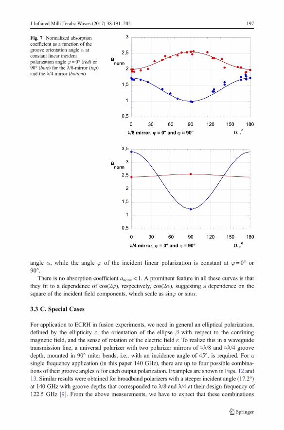
angle α, while the angle φ of the incident linear polarization is constant at φ = 0° or90°.
There is no absorption coefficient anorm<1. A prominent feature in all these curves is thatthey fit to a dependence of cos(2φ), respectively, cos(2α), suggesting a dependence on thesquare of the incident field components, which scale as sinφ or sinα.
3.3 C. Special Cases
For application to ECRH in fusion experiments, we need in general an elliptical polarization,defined by the ellipticity ε, the orientation of the ellipse β with respect to the confiningmagnetic field, and the sense of rotation of the electric field r. To realize this in a waveguidetransmission line, a universal polarizer with two polarizer mirrors of ≈λ/8 and ≈λ/4 groovedepth, mounted in 90° miter bends, i.e., with an incidence angle of 45°, is required. For asingle frequency application (in this paper 140 GHz), there are up to four possible combina-tions of their groove angles α for each output polarization. Examples are shown in Figs. 12 and13. Similar results were obtained for broadband polarizers with a steeper incident angle (17.2°)at 140 GHz with groove depths that corresponded to λ/8 and λ/4 at their design frequency of122.5 GHz [9]. From the above measurements, we have to expect that these combinations
Fig. 7 Normalized absorptioncoefficient as a function of thegroove orientation angle α atconstant linear incidentpolarization angle φ = 0° (red) or90° (blue) for the λ/8-mirror (top)and the λ/4-mirror (bottom)
J Infrared Milli Terahz Waves (2017) 38:191–205 197

have different losses. In the following, we compare for a few examples for the losses for caseswith four possible combinations. To calculate the necessary combinations of mirror angles, weassume the arrangement shown in Fig. 8 where the λ/8-mirror is followed by the λ/4-mirror.All calculations are performed for incident angles of 45°.
The apparently complicated arrangement in Fig. 8 takes into account that in ourpresent setup, we have only one place where we can insert a rotatable polarizer mirrorinto a miter bend. Therefore, we proceed in the following way: we calculate thesettings required for a two-mirror arrangement as in Fig. 8 with a linear polarizedincident field. Then, we insert the λ/8 mirror, set it to the calculated orientation αλ/8,and determine its normalized loss. Next, we insert the λ/4 mirror, set it to thecalculated value of αλ/4, feed it with an elliptic input polarization corresponding tothe calculated output of the λ/8 mirror, and determine its loss. This elliptic inputpolarization can be set by the polarizer mirrors in the MOU box. The total loss is thesum of the individual losses.
In Fig. 9, we see, for example, the case where we want as output a linear polarizedfield in horizontal direction. The left figure is obtained with a linear polarized incidentfield in φ = 0° direction (E-plane incidence), and the right figure with an incident fieldin φ = 90° direction (H-plane incidence). The four possible settings in the first casegive absorption coefficients in the range 4.2 to 5.4. In the second case, the absorptioncoefficients vary between 2.2 and 5. In order to verify that we get the proper outputpolarization, we also recorded the detector signal obtained at the directional coupler atthe end of the transmission line (Fig. 1) which must be constant in all eight cases.
In Fig. 10, we show an example for an elliptical output polarization with ε=0.418,β=76.4°, and r=−1, again with a linear input polarization either horizontal or vertical. Here
Fig. 9 Measured and calculated normalized losses for the four possible settings leading to a linear horizontaloutput polarization. Left, horizontal linear input; right, vertical linear input; dots, experimental data; lines, modelcalculation; blue, λ/8-mirror; green, λ/4-mirror; red, sum; brown, detector signal
Fig. 8 Arrangement of the twopolarizer mirrors for theexperimental examples and modelcalculations
198 J Infrared Milli Terahz Waves (2017) 38:191–205
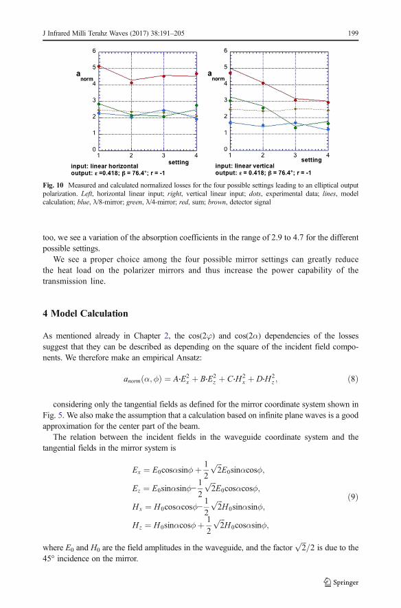
too, we see a variation of the absorption coefficients in the range of 2.9 to 4.7 for the differentpossible settings.
We see a proper choice among the four possible mirror settings can greatly reducethe heat load on the polarizer mirrors and thus increase the power capability of thetransmission line.
4 Model Calculation
As mentioned already in Chapter 2, the cos(2φ) and cos(2α) dependencies of the lossessuggest that they can be described as depending on the square of the incident field compo-nents. We therefore make an empirical Ansatz:
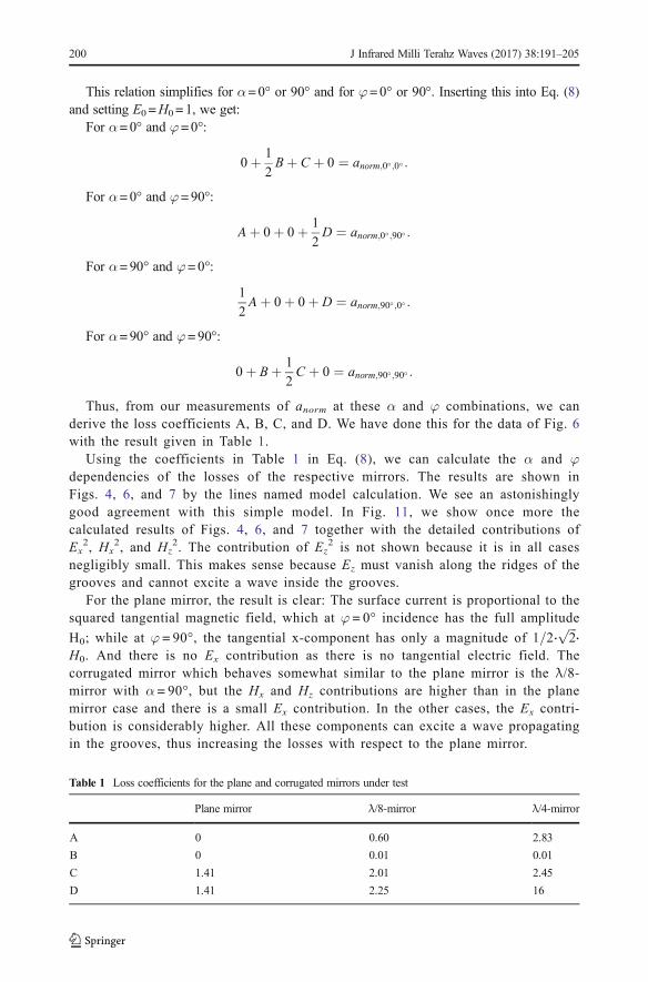
anorm α;ϕð Þ ¼ A⋅E2x þ B⋅E2
z þ C⋅H2x þ D⋅H2
z ; ð8Þ
considering only the tangential fields as defined for the mirror coordinate system shown inFig. 5. We also make the assumption that a calculation based on infinite plane waves is a goodapproximation for the center part of the beam.
The relation between the incident fields in the waveguide coordinate system and thetangential fields in the mirror system is
Ex ¼ E0cosαsinϕþ 1
2
ffiffiffi2
pE0sinαcosϕ;
Ez ¼ E0sinαsinϕ−1
2
ffiffiffi2
pE0cosαcosϕ;
Hx ¼ H0cosαcosϕ−1
2
ffiffiffi2
pH0sinαsinϕ;
Hz ¼ H0sinαcosϕþ 1
2
ffiffiffi2
pH0cosαsinϕ;
ð9Þ
where E0 and H0 are the field amplitudes in the waveguide, and the factorffiffiffi2
p=2 is due to the
45° incidence on the mirror.
Fig. 10 Measured and calculated normalized losses for the four possible settings leading to an elliptical outputpolarization. Left, horizontal linear input; right, vertical linear input; dots, experimental data; lines, modelcalculation; blue, λ/8-mirror; green, λ/4-mirror; red, sum; brown, detector signal
J Infrared Milli Terahz Waves (2017) 38:191–205 199
This relation simplifies for α=0° or 90° and for φ=0° or 90°. Inserting this into Eq. (8)and setting E0 =H0 = 1, we get:
For α=0° and φ=0°:
0þ 1
2Bþ C þ 0 ¼ anorm;0�;0� :
For α=0° and φ=90°:
Aþ 0þ 0þ 1
2D ¼ anorm;0�;90� :
For α=90° and φ=0°:
1
2Aþ 0þ 0þ D ¼ anorm;90�;0� :
For α=90° and φ=90°:
0þ Bþ 1
2C þ 0 ¼ anorm;90�;90� :
Thus, from our measurements of anorm at these α and φ combinations, we canderive the loss coefficients A, B, C, and D. We have done this for the data of Fig. 6with the result given in Table 1.
Using the coefficients in Table 1 in Eq. (8), we can calculate the α and φdependencies of the losses of the respective mirrors. The results are shown inFigs. 4, 6, and 7 by the lines named model calculation. We see an astonishinglygood agreement with this simple model. In Fig. 11, we show once more thecalculated results of Figs. 4, 6, and 7 together with the detailed contributions ofEx
2, Hx2, and Hz
2. The contribution of Ez2 is not shown because it is in all cases
negligibly small. This makes sense because Ez must vanish along the ridges of thegrooves and cannot excite a wave inside the grooves.
For the plane mirror, the result is clear: The surface current is proportional to thesquared tangential magnetic field, which at φ = 0° incidence has the full amplitude
H0; while at φ = 90°, the tangential x-component has only a magnitude of 1=2⋅ffiffiffi2
p⋅
H0. And there is no Ex contribution as there is no tangential electric field. Thecorrugated mirror which behaves somewhat similar to the plane mirror is the λ/8-mirror with α = 90°, but the Hx and Hz contributions are higher than in the planemirror case and there is a small Ex contribution. In the other cases, the Ex contri-bution is considerably higher. All these components can excite a wave propagatingin the grooves, thus increasing the losses with respect to the plane mirror.
Table 1 Loss coefficients for the plane and corrugated mirrors under test
Plane mirror λ/8-mirror λ/4-mirror
A 0 0.60 2.83
B 0 0.01 0.01
C 1.41 2.01 2.45
D 1.41 2.25 16
200 J Infrared Milli Terahz Waves (2017) 38:191–205

Our model can also be applied to the special cases of Chapter 3.3 withcombinations of λ/8 and λ/4 mirrors. The results are also shown in Figs. 9 and10 and reproduce the experimental data pretty well. The simple model given inEq. (8) is thus well suited to calculate the losses of a pair of corrugated mirrors forany setting and for any geometrical arrangement, once the coefficients A, B, C, andD for the individual mirrors are determined. It can be integrated in a polarizationmatrix code as described in [9].
Based on this finding, we can now also calculate 2D plots of the losses depending onthe rotation angles α of the λ/8 and λ/4 mirrors. In Fig. 12, we show, as an example,calculations of the output polarization for an input with horizontal linear polarization andthe configuration given in Fig. 8. Shown are 2D plots of ellipticity ε, orientation β,rotation r, and losses anorm. These figures are similar to the ones given in [9], but nowincluding losses. The data points in these graphs show the possible settings for a scan
Fig. 11 Contributions of A⋅Ex2 (blue), C⋅Hx2 (green), and D⋅Hz
2 (brown) to anorm (red) for a plane mirror (top),the λ/8-mirror with α = 0° and α = 90° (center), and the λ/4-mirror with α = 0° and α = 90° (bottom)
J Infrared Milli Terahz Waves (2017) 38:191–205 201

of the orientation β from 0 to 180° of the output polarization ellipse with ε = 0.2 androtation r = +1 (ctr. clockwise) with a horizontal linear input polarization. The dotsrepresent solutions for the required output polarization with a cross-polarizationcontent <0.1 % of the total power.
In Fig. 13, we show 2D plots for different ellipticities ε, the dots againrepresenting a β-scan. We see that at low ellipticities of ε= 0 and 0.2, there arefour solutions for the mirror settings at any value of β, whereas at the ellipticitiesε = 0.4 and 0.6, we find for some β-values only two solutions. As an example, theblack dots show the solutions for β = 60°.
In Fig. 14, we consider two cases with four solutions for which we show onlyplots of the losses. The data points are again for a scan of the orientation β from0° to 180°, but for the ellipticities ε = 0 (linear) and ε = 0.2, and both for a linearinput polarization either horizontal or vertical.
We see that the four possible settings, as shown in Fig. 14, to realize awanted output polarization have quite different total loss, both for the linear andthe elliptical output case. Lower loss can be obtained for a vertical input
Fig. 12 2D plots of the output of a two-mirror polarizer fed by a horizontal linear input polarization. a Ellipticityε. b Orientation β. c Rotation r. d Losses anorm. The dots represent a scan of the orientation β at constant ε = 0.2and r = 1. As an example, the black dots highlight the four solutions for β = 30°
202 J Infrared Milli Terahz Waves (2017) 38:191–205

polarization (H-plane incidence). This result is, however, true only for the polarizerarrangement, Fig. 8, as discussed here.
5 Discussion
Our model is not a theoretical one, rather an empirical one. The coefficients A, B,C, and D for each mirror were obtained experimentally. Normalized to perpendic-ular incidence on a plane mirror they are valid for any material, not just stainlesssteel as used here. But they will depend on the corrugation parameters like profileshape, depth, and periodicity [7]. Nevertheless, they give a guideline how to choosea setting of the polarizer mirrors which leads to lower losses. A numerical code forpolarizers like the one described in [6] should be able to calculate the coefficientsA, B, C, and D where the calculation of only four special cases according to Eq. (8)is necessary. Experimentally, the coefficients can also be obtained at low power in athree-mirror-resonator setup as in [7]. In such a setup, only cases with linear
Fig. 13 2D plots of the calculated ellipticity at the output of a two-mirror polarizer fed by a horizontal linearinput polarization. The dots represent a scan of the orientation β at rotation r = 1for constant ellipticties of a ε =0.2, b ε = 0.2, c ε= 0.4, and d ε= 0.6. As an example, the black dots highlight the solutions for β = 60°
J Infrared Milli Terahz Waves (2017) 38:191–205 203

polarization equal for input and output, and thus also only cases with parallelor perpendicular orientation of the grooves w.r.t., the E-field vector can bestudied. These are just the cases required to determine the four parameters A,B, C, and D.
Applied to a universal polarizer consisting of two corrugated mirrors as doneabove the result for the total losses will also depend on the specific arrangement:We used here the arrangement in Fig. 8, but other arrangements where the twoincidence planes are parallel or perpendicular to each other can also be treatedwith this model in the same way. One needs only to know the parameters A, B,C, and D for the applied mirrors. In general, for the proper choice of the mirrorsettings, we need also to consider the changes of the polarization along thedownstream transmission line including the launcher mirror. There is no doubtthat in the case of a complex but fixed transmission line geometry, there is alsoan optimum position for the polarizer mirrors which can be found using thismodel.
Fig. 14 2D plots of the total polarizer loss as function of the two-mirror settings α. The data points show a scanof the orientation β of the output polarization ellipse from 0° to 180° at constant ellipticity ε and constant rotationr. As an example, the black dots highlight the four solutions for β = 60°. a Input, horizontal linear; output, ε = 0,r = ±1 (lin. pol.). b Input, vertical linear; output, ε = 0, r = ±1 (lin. pol.). c Input, horizontal linear; output, ε = 0.2,r = +1 (ell. pol.). d Input, vertical linear; output, ε = 0.2, r = +1 (ell. pol.)
204 J Infrared Milli Terahz Waves (2017) 38:191–205

Acknowledgments Wewould like to thank our colleagues F. Monaco and H. Schütz for their valuable help in settingup and performing the high-power experiments and for proposing to use a PT-100 detector instead of a thermocouple.
Open access funding provided by Max Planck Society.
Open Access This article is distributed under the terms of the Creative Commons Attribution 4.0 InternationalLicense (http://creativecommons.org/licenses/by/4.0/), which permits unrestricted use, distribution, and repro-duction in any medium, provided you give appropriate credit to the original author(s) and the source, provide alink to the Creative Commons license, and indicate if changes were made.
References
1. M.I. Petelin, Proc. First Intl. Workshop on Electron Cyclotron Resonance Heating Transmission Systems,Proc. First Intl. Workshop on Electron Cyclotron Resonance Heating Transmission Systems (Cocoa Beach,Florida, 1990).
2. J.L. Doane et al., Polarizer miter bends for high-power microwave transmission: Ohmic loss and cooling,Fusion Engineering and Design, Vol. 102 (2016), 99-107.
3. Y. Kashiwa et al., Study of Ohmic loss of high power polarizers at 170 GHz for ITER, Fusion Engineeringand Design, Vol. 81 (2006), 2249-2256.
4. D. Wagner et al., New frequency step-tunable ECRH System for ASDEX Upgrade, International Journal ofInfrared and Millimeter Waves, Vol. 27 (2006), 173-182.
5. V. Erckmann, P. Brand, H. Braune, G. Dammertz, G. Gantenbein, W. Kasparek, H.P. Laqua, H. Maassberg,N.B. Marushchenko, G. Michel et al., Electron Cyclotron Heating for W7-X: Physics and Technology,Fusion Science and Technology 52, 291 (2007)
6. B. Plaum et al., Numerical Calculation of Reflection Characteristics of Grooved Surfaces with a 2D FDTDAlgorithm, Journal of Infrared, Millimeter and Terahertz Waves, Vol. 32 (2011), 482-495.
7. W. Kasparek et al., Measurement of ohmic loss of metallic reflectors at 140 GHz by a 3-mirror resonatortechnique, Int. J. Infrared Millimeter Waves, Vol. 22 (2001), 1695-1707.
8. D. Wagner et al, Status, Operation and Extension of the ECRH System at ASDEX Upgrade, InternationalJournal of Infrared, Millimeter and Terahertz Waves, Vol. 37 (2016), 45-54.
9. D. Wagner, F. Leuterer, Broadband polarizers for high power multi-frequency ECRH systems, Journal ofInfrared, Millimeter and Terahertz Waves, Vol. 26 (2005), 163-172.
10. M.K. Thumm, W. Kasparek, Passive High-Power Microwave Components, IEEE Trans. on PlasmaScience, Vol. 30, No. 3 (2002), 755 – 786.
J Infrared Milli Terahz Waves (2017) 38:191–205 205