Embed Size (px)
Citation preview

MINING ENGINEERING
BTECH
LAB MANUAL
MINING SURVEYING I
Kamre | Ratu Road | Ranchi | Jharkhand
JRU/MiE/ MINE SURVEYING 1
LIST OF EXPERIMENTS
Sl. Name of the Experiment
Page No.
No.
1. Measurement of distance by Ranging and Chaining. 3
2. Locating various object by chain & cross staff survey 6
3. Measurement of bearings of sides of traverse with 9
prismatic compass and computation of correct
included angle.
4. To find the difference in elevation between two 15
points using Differential or Fly leveling.
5. Calculation of R.L. for different points 18
involving 2 instrument stations & reduction by
Height of Instrument & Rise and Fall methods.
6.
Study of plane table surveying equipment’s and accessories. Three point problem in plane table traversing. 21
7.
Study of Auto Level and Dumpy Level; To study different parts of a Transit Theodolite and Temporary Adjustments. 25
8.
To determine the distance between two inaccessible
points by the help of a Compass. 32
JRU/MiE/ MINE SURVEYING 1
EXPERIMENT NO. 01
AIM: Measurement of distance by Ranging and Chaining.
INSTRUMENTS: Chain, Arrows, Tapes, Ranging Rods, Offset Rods, Cross staff or optical square, Plumb
bob, wooden mallet, pegs.
FIGURE:
THEORY: By the various methods of determining distance the most accurate and common method is the
method of measuring distance with a chain or tape is called Chaining. For work of ordinary
precision a chain is used. But where great accuracy is required a steel tape is invariably used. The term chaining was originally applied to measure Distance with a chain. The term chaining is
used to denote measuring distance with either chain or tape, In the process of chaining, The Survey party consists of a leader (the surveyor at the forward end of the chain) a follower (the

JRU/MiE/ MINE SURVEYING 1
surveyor at the rare end of the chain and an assistant to establish intermediate points). The
accuracy to which measurement can be made with chain and tape varies with the methods used
and precautions exercised. The precision of chaining. For ordinary work, ranges from 1/1000 to
1/30,000 and precise measurement such as Baseline may be of the order of 1000000. The chain
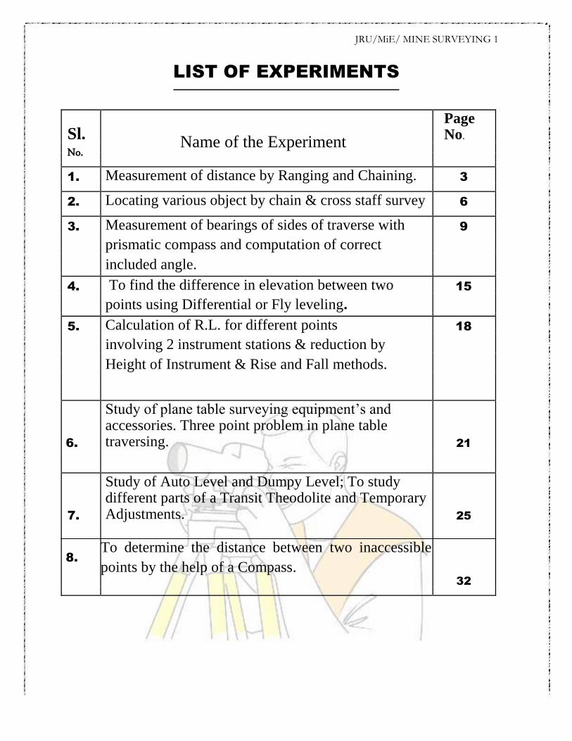
is composed of 100 or150 pieces of galvanized mild steel were 4mm in diameter called links.
The end of each link is bent into a loop and connected together by means of three oval rings
which afford flexibility To the chain and make it less liable to become kinked. The ends of chain
are provided with brass handles for dr agging the chain on the ground, each with a swivel Joints
so that the chain can be turned round without twisting. The length of the A link is the distance
between the centres of the two consecutive middle rings.The end links include the handles
metallic rings indicators of distinctive points of the Chain to facilitate quick reading of fractions
of chain in surveying measurements.
RANGING RODS:
The ranging rods are used for marking the positions of Stations
conspicuously and for ranging the lines. Io order to make these
visible at a distance, they are painted alternately black and white, or
red and white or red White and black successively. The adjustment
of the chain should as far as possible be affected symmetrically on
either side of the middle so as that the position of central tag
remains unaltered. In measuring the length of survey line also
called as chain line. It is necessary that the chain should be laid out
on the ground in a straight line between the end stations.
PROCEDURE: Two men are required for chaining operation; the chain man at the forward end of chain is

JRU/MiE/ MINE SURVEYING 1 called the leader while the other man at the rear end is known as the follower. Duties of leader &follower Leader:- 1) To put the chain forward 2) To fix arrows at the end of chain 3) To follow the instruction of the followers
Follower:- 1) To direct the leader to the line with the ranging rod. 2) To carry the rear end of the chain. 3) To pick up the arrows inserted by the leader. Chaining 1) The follower holds the zero handle of the chain against the peg &directs the leader to be in
line of the ranging rod. 2) The leader usually with to arrows drags the chain alone the line. 3) Using code of signals the follower directs the leader as required to the exactly in the line. 4) The leader then fixes the arrows at the end of chain the process is repeated. Ranging 1) Place ranging rods or poles vertically behind each point 2) Stand about 2m behind the ranging rod at the beginning of the line. 3) Direct the person to move the rod to right or left until the three ranging rods appear exactly
in the straight line. 4) Sight only the lower portion of rod in order to avoid error in non-vertically. 5) After ascertaining that three rods are in a straight line, ask the person to fix up the rod. RESULT: By Chaining and ranging the total distance is found to be______________ PRECAUTIONS: Write down the precautions you have taken during this experiment in field.
*******************

JRU/MiE/ MINE SURVEYING 1
EXPERIMENT NO. 02
AIM: Locating various object by chain & cross staff survey INSTRUMENTS: Chain, Ranging rod, Arrows, Cross-staff, Metallic Survey (Tape) FIGURE:
THEORY: Cross-Staff is the simplest instrument used for setting out perpendicular i.e taking offsets from a
chain line. it is easier and quicker method ,but not very accurate . If great accuracy is desired ,the
work should be carried out by the theodolite. Open cross staff:- The simplest Type consists two parts 1) the head 2) the leg .the head is made
of wooden block octagonal or round in shape about 15cm side or diameter an 4cm deep . on it
are scribed two lines at right angles to another .At the end of these 4cm deep . on it are scribed
two lines at right angles to another .At the end of these lines of sight which are at right angles to

JRU/MiE/ MINE SURVEYING 1 one another .The head is fixed on a wooden staff or pole about 3cm in diameter and 1.2 to 1.5m
length .The pole is provided conical metal shoe so that it can be driven into the ground.

JRU/MiE/ MINE SURVEYING 1 PROCEDURE:
1. To find the foot of the perpendicular from the object the cross staff is held approximately
in position and one pair of slits is directed in the direction of the ranging rod fixed at the
forward and the chain line . The observer then looks through the other pair of slits and
sees whether the particular object is bisected or not. if not the cross staff is moved to and
from till the necessary bisection is obtained. Before noting down the chainage of the foot
of the perpendicular care must be taken to see that one pair of slit is the direction of chain
or not. While shifting the position of the cross-staff it may get twisted and hence
precaution is necessary.
2. To set a perpendicular to the chain line at a given point one pair of slits is oriented in the
direction of chain line by looking at the ranging rod fixed at the forward and by looking
through the other pair of slits ranging rod is fixed in the direction of the line of sight
provided by this pair.
RESULT: Various perpendicular to the chain line object are created using cross-staff survey. PRECAUTIONS: Write down the precautions you have taken during this experiment in field.
*******************
JRU/MiE/ MINE SURVEYING 1
EXPERIMENT NO. 03
AIM: Measurement of bearings of sides of traverse with prismatic compass and
computation of correct included angle.
INSTRUMENTS: Prismatic compass, ranging rod, chain, tape, peg Tripod stand , small pieces of stones.
FIGURE:

JRU/MiE/ MINE SURVEYING 1
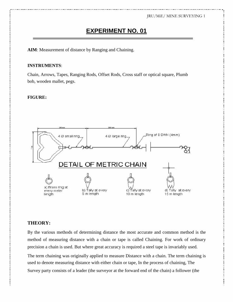
THEORY: The important parts of compass are:- 1) A box with graduated circle. 2) A magnetic needle 3) A
line of sight When the line of sight is pointed to point, the magnetic needle of compass points
towards north (Magnetic meridian). The angle which this line of sight makes with the magnetic
meridian is read on graduated circle. It is known as magnetic bearing of the line. There are two
types of compasses: - 1) Prismatic compass 2) Surveyor’s compass. Prismatic Compass :-
rismatic compass is very valuable instrument. It is usually used for rough survey for measuring
bearing and survey lines. The least count of prismatic compass is 30 min. It consists of circular
box of 10cm-12 cm dia. of non magnetic material. pivot is fixed at the centre of box and is made
up of hard steel with a Sharp pivot. Graduated aluminum is attached to the needle. It is graduated
in clockwise direction from 0o to 360
o. The figures are written in inverted. Zero is written at
south end and 180 at north end and 270 at the east. Diametrically opposite are fixed to the box.
The sighting vane consists of a hinged metal frame in the centre of which is stretched a vertical
Horse hair fine silk thread of which is stretched a vertical hair. it presses against a lifting pin
which lift the needle of the pivot and holds it against the glass lid. Thus preventing the wear of
the pivot point to damp the oscillations of the needle when about to take reading and to bring to
rest quickly, a light spring is brought lifted Inside the box. The face of the prism can be folded
out the edge of the box when North end is used Sometime the sighting vanes is provided with a
hinge mirror Which can be placed upward or downwards on the frame and can be also Slided
along it is required. The mirror can be made inclined at any angle so that Objects which are too
high or too low can be sighted directly by reflecting. BEARING OF LINES: A bearing of a line is a horizontal angle made by the survey line with
some reference direction or meridian. Meridian may be 1) A true meridian 2) A magnetic meridian 3) An arbitrary or assumed meridian True meridian: The true geographical meridian passing through a point is a line of intersection of
earth’s surface by a plane containing north south pole and given point. They are not parallel to
each other at different places. Magnetic meridian:-the direction indicates by a free suspended and
a properly balanced magnetic needle Free from all other attractive forces. The direction of
magnetic meridian can be established with the help of Magnetic compass.
JRU/MiE/ MINE SURVEYING 1
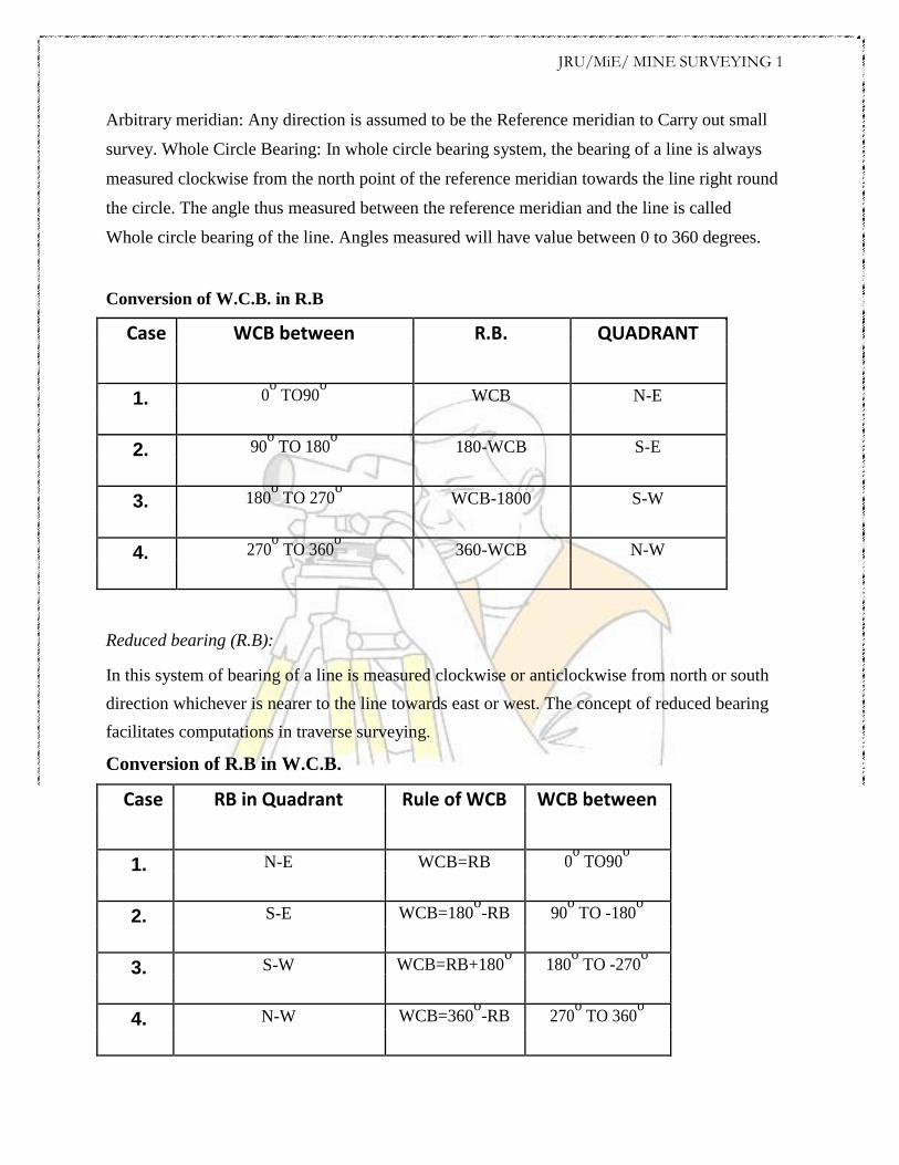
Arbitrary meridian: Any direction is assumed to be the Reference meridian to Carry out small
survey. Whole Circle Bearing: In whole circle bearing system, the bearing of a line is always
measured clockwise from the north point of the reference meridian towards the line right round
the circle. The angle thus measured between the reference meridian and the line is called
Whole circle bearing of the line. Angles measured will have value between 0 to 360 degrees.
Conversion of W.C.B. in R.B
Case WCB between R.B. QUADRANT
1. 0o TO90
o WCB N-E
2. 90o TO 180
o 180-WCB S-E
3. 180o TO 270
o WCB-1800 S-W
4. 270o TO 360
o 360-WCB N-W
Reduced bearing (R.B): In this system of bearing of a line is measured clockwise or anticlockwise from north or south
direction whichever is nearer to the line towards east or west. The concept of reduced bearing
facilitates computations in traverse surveying. Conversion of R.B in W.C.B.
Case RB in Quadrant Rule of WCB WCB between
1. N-E WCB=RB 0o TO90
o
2. S-E WCB=180o-RB 90
o TO -180
o
3. S-W WCB=RB+180o 180
o TO -270
o
4. N-W WCB=360o-RB 270
o TO 360
o
JRU/MiE/ MINE SURVEYING 1 Adjustment of the Prismatic Compass: The compass may be held in hand but for better results it should be fitted at the top of tripod
having ball and socket arrangement. The adjustment of a compass is done in the following three
steps. 1) Centering: - The compass fitted over the tripod Is lifted bodily and placed
approximately on the station peg by spreading the leg of a tripod equally, The centre of the
compass is checked by dropping a small piece of stone from the centre of the bottom of the
compass so that it falls on the top of the station peg. A plumb bob may be used to judge the
centering either bt attaching it with a hook providing at the bottom or otherwise by holding it by
hand. 2) Levelling:-After the compass is centred, it is leveled by means of ball and soket
arrangement so that the graduated circle may swing freely.It can be checked roughly by placing a
round pencil on the top of the compass, when the pencil does not move, that is roughly the
horizontal position. 3) Focusing the prism: - The prism attached is moved up and down so that
grauation on the graduated circle should become sharp and clear. LOCAL ATTRACTION: Sometimes .the magnetic needle does not point towards magnetic North or South. The reason
being that the needle may be under the influence of external attractive forces which are produced
due to magnetic substances Thus the deflection of the needle from its original position, due to the
presence of some magnetic substances is known as local attraction. To detect local attraction at a
particular place, fore and back bearing of each line are taken. Then difference comes out to be
180° there is no local attraction at either station. On the other hand of the difference is other than
180°,the bearing may be rechecked to find out the discrepancy may not be due to the presence of
iron substance near to the compass. If the difference still remains the local attraction exists at on
or both the stations. Elimination of Local attraction:- 1st method: - In this method, the bearing of
the other lines are corrected and calculated on the basis of the a line which has the difference
between its fore bearing and back bearing equal to 180°. The magnetic of the error is formed due
to local attraction by drawing a sketch of observed and correct bearing of the line at each station.
The error will be negative when the observed bearing is less than the corrected one and the
correction will be positive and vice versa. If however, there is no such line in which the
difference of fore bearing and back bearing is equal to 180°, the correction should be made from
the mean value of the bearing of that line in which the difference between the fore and the back
JRU/MiE/ MINE SURVEYING 1 bearing is the least. If the bearings are observed in Quadrantal system, the correction should be
applied in proper direction by drawing a neat sketch roughly. 2nd Method: - This method is more
general as the bearing at a station locally affected may be incorrect but include angles calculated
from these bearing will be correct since the amount of the error will be the same for all the
bearing observed from that station. Thus starting from the unaffected line and using these
included angles the correct bearing of all other lines can be calculated. Note: - The sum of the
internal included angles must be equal to (2n-4) right angles where n=number of sides of a
closed traverse. PROCEDURE:
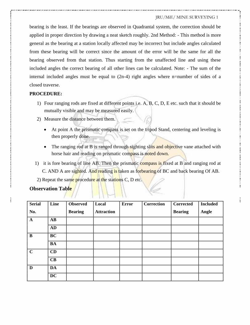
1) Four ranging rods are fixed at different points i.e. A, B, C, D, E etc. such that it should be
mutually visible and may be measured easily.
2) Measure the distance between them.
At point A the prismatic compass is set on the tripod Stand, centering and leveling is
then properly done.
The ranging rod at B is ranged through sighting slits and objective vane attached with
horse hair and reading on prismatic compass is noted down.
1) it is fore bearing of line AB. Then the prismatic compass is fixed at B and ranging rod at
C. AND A are sighted. And reading is taken as forbearing of BC and back bearing Of AB.
2) Repeat the same procedure at the stations C, D etc. Observation Table
Serial Line Observed Local Error Correction Corrected Included
No. Bearing Attraction Bearing Angle
A AB
AD
B BC
BA
C CD
CB
D DA
DC
JRU/MiE/ MINE SURVEYING 1
SAMPLE CALCULATION:- Error = observed bearing –corrected bearing
Check = (2n-4) x 90o
RESULT: The prismatic compass is studied and bearing of lines of traverse are Observed, the correction
due to local attraction at affected station is done and corrected bearings are written in tabular
form.
*******************

JRU/MiE/ MINE SURVEYING 1
EXPERIMENT NO. 04
AIM: To find the difference in elevation between two points using Differential or Fly levelling. INSTRUMENTS: 1.) Dumpy level.
2.) Leveling staff.
FIGURE:

JRU/MiE/ MINE SURVEYING 1
THEORY: Differential Levelling is the method of levelling which is employed for the determination of
elevation difference between two points located far apart from each other.. It is done regardless
of the horizontal positions of the points with respect to each other. The staff is kept at a point
unless both a fore sight and back sight reading is obtained with instrument placed at two different
stations. It is also sometimes known as taking fly levels or simply fly leveling. The levelling
instrument is set up at a number of points and the difference in the elevation of successive points
is determined until we reach the final point which was the point of interest
PROCEDURE:
1. Set up the level at O1 ensuring that the line of sight intersects the staff held at A. Level it
correctly.
2. With the bubble central take the back staff reading on the staff held vertically at A.
Record it as x1.
3. Select a point C roughly equidistant from the instrument position O1 and take the
foresight reading on the staff held vertically at C. Record it as y1
4. Shift the instrument to O2, set up and level it correctly.
5. With the bubble central take the back sight reading at the staff held vertically on C
again. Record it as x2.
6. Select another point equidistant from the instrument position O2 and take the foresight
reading on the staff held vertically at this point. Record it as y1
7. Keep repeating the above process until the foresight reading is finally taken on the staff
placed at the final point of interest. NOTE:
The back sight readings are recorded as x1, x2, x3, x4…… and the foresight readings are
recorded as y1, y2, y3, y4, ……
The points for which both back sight and foresight readings are recorded are known
as CHANGE points. The staff is not moved from these points until the foresight
reading from a new instrument station is taken.
JRU/MiE/ MINE SURVEYING 1
CALCULATION: The difference of level between consequent staff location =x1-y1, x2-y2,x3-y3…..and so on. The difference in level of initial and final point= Algebraic sum of B.S. - Algebraic sum of F.S.
RESULT: Difference in elevation between A and D = ……………
*******************

JRU/MiE/ MINE SURVEYING 1
EXPERIMENT NO. 05
AIM: Calculation of R.L. for different points involving 2 instrument stations & reduction by
Height of Instrument & Rise and Fall methods.
INSTRUMENTS: 1. Auto Level with a tripod Stand 2. Measuring tape 3. Leveling staff.
FIGURE:
THEORY: If we know the reduced level of a point in the field, we can use it as a bench mark to determine
the R.L. of various points around it. The change of instrument station if needed can be
incorporated by sighting a point which was earlier sighted as the Foresight for the previous
station and be noted as the backsight for the new station. This helps us to achieve a reference for
the new point of observation. The intermediate sights and foresights is preferably kept
equidistant to the backsight on the bench mark. Once the I.S. or F.S. crosses the B.S. distance we

JRU/MiE/ MINE SURVEYING 1
change the instrument to another suitable position for further readings. The two methods used to
reduce the field observation into useful data are : Height of instrument method and Rise & Fall
Method. PROCEDURE:
1. Setup the auto level instrument at a convenient point- instrument station-1 and carry out
the temporary adjustment
2. Take the back Sight on the benchmark whose reduced level is known. If the R.L. is
unknown assume a suitable value. Assumption leads to a relative study of elevation of
different points with a particular reference. Record this reading under the column B.S. of
the field book.
3. Take the staff to the first point A. Record the reading under the I.S. column.
4. Take the staff to the point B. Sight the staff through the telescope and record the reading
again under I.S. The same method is repeated for the staff placed at point C
5. Place the staff at point D and sight through the telescope. The observed reading is noted
under the F.S. Column.
6. Keep the staff at the same point and shift the instrument to the new location – Instrument
station 2
7. Carry out the temporary adjustments and sight the staff which is still held vertical at point
D. This can be noted as the B.S. for the new position of instrument.
8. Keep sighting the further points E,F,G and record the value on staff under I.S.
9. Finally G is sighted through the telescope and recorded under F.S. for the Second
instrument station. Note: After the field work is over the recorded details can be used to determine the R.L. of the
points A, B, C, D, E,F,G by either Height of Instrument method or Rise and Fall method.
CALCULATION & RESULT:
Table for HEIGHT OF INSTRUMENT method.
Serial B.S. I.S. F.S. Height of Reduced
(Back Sight) (Intermediate Sight) (Fore Sight) Collimation Level
B.M.

JRU/MiE/ MINE SURVEYING 1 A
B
C
-
-
-
-
H.I.= B.S.+ R.L. of Bench Mark
R.L. of A = H.I.- I.S.
R.L. of B = H.I.- I.S…. And so on
Table for RISE & FALL method.
READINGS
Station. RISE FALL R.L. B.S. I.S. F.S.
B.S- I.S. = +ve -
Rise or –ve
Fall
R.L. of a point = Previous R.L. + Rise or – Fall
CHECK:
Σ B.S – Σ F.S = Σ Rise – Σ Fall = Last R.L. – First R.L
*******************
JRU/MiE/ MINE SURVEYING 1
EXPERIMENT NO. 06
AIM : Study of plane table surveying equipment’s and accessories. Three point problem in plane
table traversing.
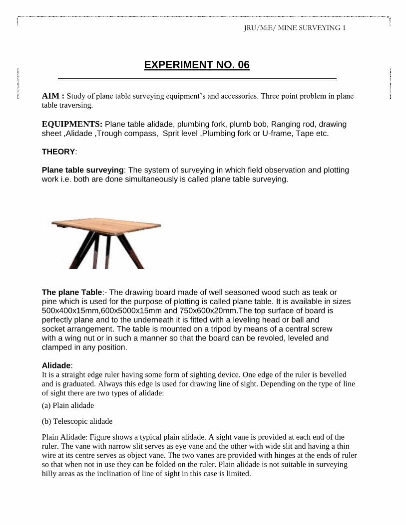
EQUIPMENTS: Plane table alidade, plumbing fork, plumb bob, Ranging rod, drawing sheet ,Alidade ,Trough compass, Sprit level ,Plumbing fork or U-frame, Tape etc. THEORY: Plane table surveying: The system of surveying in which field observation and plotting work i.e. both are done simultaneously is called plane table surveying.
The plane Table:- The drawing board made of well seasoned wood such as teak or pine which is used for the purpose of plotting is called plane table. It is available in sizes 500x400x15mm,600x5000x15mm and 750x600x20mm.The top surface of board is perfectly plane and to the underneath it is fitted with a leveling head or ball and socket arrangement. The table is mounted on a tripod by means of a central screw with a wing nut or in such a manner so that the board can be revoled, leveled and clamped in any position. Alidade: It is a straight edge ruler having some form of sighting device. One edge of the ruler is bevelled
and is graduated. Always this edge is used for drawing line of sight. Depending on the type of line
of sight there are two types of alidade:
(a) Plain alidade
(b) Telescopic alidade
Plain Alidade: Figure shows a typical plain alidade. A sight vane is provided at each end of the
ruler. The vane with narrow slit serves as eye vane and the other with wide slit and having a thin
wire at its centre serves as object vane. The two vanes are provided with hinges at the ends of ruler
so that when not in use they can be folded on the ruler. Plain alidade is not suitable in surveying
hilly areas as the inclination of line of sight in this case is limited.

JRU/MiE/ MINE SURVEYING 1
Trough Compass:The compass which is used to mark the direction of the magnetic meridian on the plane table is called trough compass. It consist of a long narrow rectangular nonmagnetic metallic box 8cm to 15cm long,3cm to 5cm wide and 2cm to 3cm high on the covered with a glass cover. it the centre of the box is provided a magnetic needle with a agate stone mounted on the sharp steel pivot. At the end the through compass graduated scales are with zero degree at the centre and up to 5° on either side of the zero line .A counter weight is also used for North end of the needle to represent North and is also used for balancing the dip of the needle. Sprit Level:- A small sprit level circular or rectangular is required for seeing if the table is properly level. The level must have flat base so that it can be placed on the table. Plumbing fork or U-frame :- The plumbing fork to which is attached a plumb bob ,used for centering the plane table over the station occupied by the plane table. it is also meant for transforming the ground point on to sheet so that both the points should be in the same vertical lineIt consists of two light metal arms as shown in fig. approximately of equal lengths. A hook for suspending a plumb bob is provided at the lower arm immediately below the end point of the upper arm. The upper arm is placed on the plane table while the lower arm with a plumb bob is moved below the table for centering over the ground station mark, thus in the exact position the pointed end of the upper arm will give the corresponding position on the paper.

JRU/MiE/ MINE SURVEYING 1 Three point problem in plane table surveying: It is finding the location of the station occupied by a plane table on the sheet, by means of sighting to three well-defined points of known location on the sheet.The principle of this method lies in the fact that if the plane table is correctly oriented, the three resectors through a ,b,& c, shown in fig. meet at a point p which is the location of the plane-table station on the sheet, provided the points A,B,C& P do not lie on the circumference of a circle. By solving three- point problem, thus, the orientation & resection are accomplished simultaneously. The solution of three-point problem is further illustrated graphically in fig. the stations A, B, & C are of known position & p is of unknown position. If the angle a is observed between PB, & PA, the position of P is indeterminate, because P can be anywhere on the circle circumscribing the triangle PAB. Additional information is needed to make the problem determinate. If the angle B, which is the angle subtended by AC at P, is also observed then the solution is unique since P, A &C lie on the circle that circumscribe triangle PAC, & P is one of the two intersection points of the circles & A is the other intersection point. This solution becomes indeterminate of A, B, C, & P fall on the circumference of one circle. If the two circles tend to merge into one circle, the problem will be less stable & finally becomes indeterminate again when the two circles coincide. Points should be selected in the field so as to avoid this situation. There is number of solutions of three-point problem but the following methods applicable to the plane table discussed. a. mechanical method ( tracing paper method ) b. graphical method c. trial & error method ( Lehmann’s method )

JRU/MiE/ MINE SURVEYING 1
PROCEDURE:
1. Let ABC be the three points where distance are known. The table is set at ’P’.
The table is oriented approximately so that abc is parallel to ABC.
2. Keep the alidade on the line in ‘a’ and rotate the table till ‘A’ is bisected. Then
clamp the table.
3. Pivoting the alidade on the line ‘b’ sight to’l’ and draw the ray ‘xy’ along the
edge of the alidade.
4. Keep the alidade along ‘ab’ sight ‘B’ and rotate till B is bisected. Clamp the
table.
5. Pivot the alidade about a sight to ‘C’. Draw a ray along the edge to intersect
the ray ‘xy’ at ‘c’.Join cc1.
6. Keep the alidade along cc1 rotate the table till C1 is bisected. Clamp the table.
The table is correctly oriented.
7. Pivoting the alidade about ‘b’ sight to B1 . Draw a ray to intersect cc1
at P. Similarly if the alidade is pivoted about a and A is sighted the ray will
pass through the point ‘p’ if the survey is accurate.
The problem may be solved by (1) Mechanically (2) Graphically (Bessel’s method) & (3) By trial & error method.
RESULT:
Thus the position of station occupied by the plane table is determined by three point problem using “Bessels” Graphical Solution.

JRU/MiE/ MINE SURVEYING 1
EXPERIMENT NO. 07
AIM : Study of Auto Level and Dumpy Level and to study different parts of a Transit Theodolite and
Temporary Adjustments.
EQUIPMENTS:
Transit – Theodolite
FIGURE:
JRU/MiE/ MINE SURVEYING 1
IMPORTANT DEFINITIONS:
VERTICAL AXIS:
It is the axis about which the telescope can be rotated in a horizontal plane.
HORIZONTAL AXIS:
It is the axis about which the telescope can be rotated in a vertical plane.
LINE OF COLLINATION:
It is the imaginary line joining the intersection of the cross hairs of the diaphragm
to the optical center of the object glass and its continuation.
AXIS OF THE TELESCOPE:
It is the line joining the optical center of the object glass to the center of the eye-piece.
AXIS OF THE LEVEL TUBE:
It is the straight line tangential to the longitudinal curve of the level tube at the center of
the tube.
CENTERING:
The process of setting the theodolite exactly over the station mark is known as centering.
TRANSITING:
It is the process of turning the telescope in vertical plane through 180º about the
trunnion axis.
SWINGING THE TELESCOPE:
It means turning the telescope about its vertical axis in the horizontal plane. A swing is
called right or left according as the telescope is rotated clockwise or counter clockwise.
FACE LEFT:
If face of the vertical circle is to the left side of the observer, then the observation
of the angles taken is known as face left observation.
FACE RIGHT:
If the face of the vertical circle is to the right side of the observation, then the observation
of the angles taken is known as face right observation.
CHANGING FACE:
It is an operation of bringing the face of the telescope from left to right and vice-versa.
JRU/MiE/ MINE SURVEYING 1
DESCRIPTION OF DIFFERENT COMPONENTS:
o TELESCOPE:
It consists of eye-piece , object glass and focusing screw and it is used to sight
the object.
o VERTICAL CIRCLE:
It is used to measure vertical angles.
o LEVELLING HEAD:
It consists of two parallel triangular plates called tribach plates. It is used
1. To support the main part of the instrument.
2. To attach the theodolite to the tripod.
o LOWER PLATE:
It consists of lower clamp screw and tangent screw.
o UPPER PLATE:
The upper plate is attached to the inner axis and it carries two verniers. It consists an upper
clamp screw and tangent screws. These screws are used to fix upper plate with lower plate
accurately.
o FOOT SCREWS:
These are used to level the instrument
o PLUMB BOB:
It is used to center theodolite exactly over the ground station mark.
TEMPORARY ADJUSTMENTS:
There are three temporary adjustments of a theodolite. These are:
1. Setting up the theodolite over a station.
2. Leveling up.
3. Elimination of parallax. SETTING UP:
It includes two operations
1. Centering a theodolite over a station: Done by means of plumb bob. Recently use of optical
plummet has made the job of centering very easy.
2. Approximately leveling it by tripod legs only: Done by moving tripod legs radially or
JRU/MiE/ MINE SURVEYING 1 circumferentially.
LEVELING UP:
Having centered and approximately levelled the instrument, accurate levelling is done with
the help of foot screws with reference to the plate levels, so that the vertical axis shall be truly
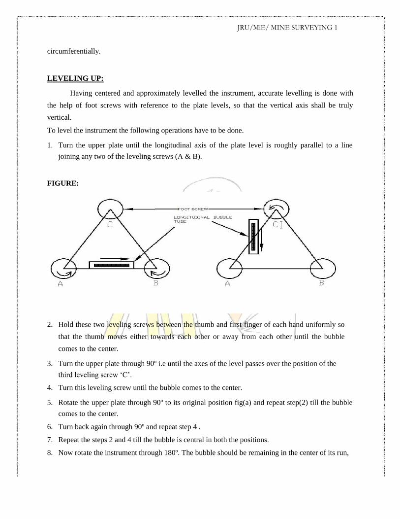
vertical. To level the instrument the following operations have to be done. 1. Turn the upper plate until the longitudinal axis of the plate level is roughly parallel to a line
joining any two of the leveling screws (A & B).
FIGURE: 2. Hold these two leveling screws between the thumb and first finger of each hand uniformly so
that the thumb moves either towards each other or away from each other until the bubble
comes to the center. 3. Turn the upper plate through 90º i.e until the axes of the level passes over the position of the
third leveling screw ‘C’. 4. Turn this leveling screw until the bubble comes to the center. 5. Rotate the upper plate through 90º to its original position fig(a) and repeat step(2) till the bubble
comes to the center. 6. Turn back again through 90º and repeat step 4 . 7. Repeat the steps 2 and 4 till the bubble is central in both the positions. 8. Now rotate the instrument through 180º. The bubble should be remaining in the center of its run,
JRU/MiE/ MINE SURVEYING 1
provided it is in correct adjustment. The vertical axis will then be truly vertical.
ELIMINATION OF PARALLAX:
Parallax is a condition arising when the image formed by the objective is not in the plane of the cross
hairs. Unless parallax is eliminated, accurate sighting is not possible. Parallax can be eliminated in two steps.
1. FOCUSSING THE EYE-PIECE:
Point the telescope to the sky or hold a piece of white paper in front of the telescope. Move the
eyepiece in and out until a distant and sharp black image of the cross-hairs is seen.
2. FOCUSSING THE OBJECT:
Telescope is now turned towards object to be sighted and the focusing screw is turned until
image appears clear and sharp.
AUTO LEVEL AND DUMPY LEVEL:
THE LEVEL:- The instrument which is used for measuring related elevations is known as a level and consists of the following
parts.
1. A telescope to provide a line of sight.
2. A level tube to make the line of sight horizontal.
3. A leveling head to bring the rubber of the level tube at the centre of its run.
TYPES OF LEVEL: -
DUMPY LEVEL:
1. This consists of a telescope rigidly fixed to its supports.
2. It can neither be rotated about its longitudinal axis nor it can be removed from the support. WYE LEVEL:
1. The telescope is supported in y-support ant its rigidly fixed to the supports.
2. The telescope can be removed from the supports reversed end to end can be removed about in longitudinal axis.
REVERSIBLE LEVEL: 1. The telescope can be rotated about its longitudinal axis in the sockets and also can be wth drawn from its
sockets and replaced end for end.
JRU/MiE/ MINE SURVEYING 1
TILTING LEVEL:
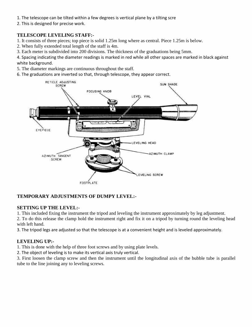
1. The telescope can be tilted within a few degrees is vertical plane by a tilting scre 2. This is designed for precise work. TELESCOPE LEVELING STAFF:- 1. It consists of three pieces; top piece is solid 1.25m long where as central. Piece 1.25m is below.
2. When fully extended total length of the staff is 4m.
3. Each meter is subdivided into 200 divisions. The thickness of the graduations being 5mm.
4. Spacing indicating the diameter readings is marked in red while all other spaces are marked in black against white background. 5. The diameter markings are continuous throughout the staff.
6. The graduations are inverted so that, through telescope, they appear correct.
TEMPORARY ADJUSTMENTS OF DUMPY LEVEL:-
SETTING UP THE LEVEL:- 1. This included fixing the instrument the tripod and leveling the instrument approximately by leg adjustment.
2. To do this release the clamp hold the instrument right and fix it on a tripod by turning round the leveling head
with left hand.
3. The tripod legs are adjusted so that the telescope is at a convenient height and is leveled approximately. LEVELING UP:- 1. This is done with the help of three foot screws and by using plate levels.
2. The object of leveling is to make its vertical axis truly vertical. 3. First loosen the clamp screw and then the instrument until the longitudinal axis of the bubble tube is parallel
tube to the line joining any to leveling screws.

JRU/MiE/ MINE SURVEYING 1
4. Holding the two foot screws with the thumb and first finger of each hand moves either towards each other or
away from each other until the bubble comes to the center.
5. Rotate the upper plate through 50º until the axis of the plate level coincide a line joining the third foot screw c
and the midpoint of the first two screw A and B.
6. Hold the third screw with thumb and fore finger of the hand and turn it will plate bubble is central.
7. Rotate the upper plate through 90º to its original position.
8. Rotate again through 90º and step 6 is repeated.
9. Steps 4 and 6 are repeated until the bubbles remain central in both the position.
10. The instrument is rotated through 180 º and in this position the bubble should remain central if the instrument
is adjusted.
ELIMINATION OF PARALLAX:- 1. Parallax is a condition a rising when a image formed by objective is not in plane cross hairs.
2. To get accurate sighting this should be eliminated and this is done by
Focusing the eyepiece for distinct vision of cross hairs.
Focusing the objective to bring the image of the objective in the plane of cross hairs.
VIVA QUESTIONS:
1. State any four uses of a theodolite?
2. What is meant by face left and face right?
3. What does swinging of telescope means?
4. What is meant by transiting? 5. What is levelling staff and its least count?
*******************
JRU/MiE/ MINE SURVEYING 1
EXPERIMENT NO. 08
AIM: To determine the distance between two inaccessible points by the help of a prismatic compass. EQUIPMENTS: Prismatic compass, arrows, tape, ranging rods, pegs.
PROCEDURE:
If there is an obstacle between two points say A and B due To which direct
distance measurement is not possible the those points are called As inaccessible
points and distance between them is to be determined indirectly.
By following the procedure described below:
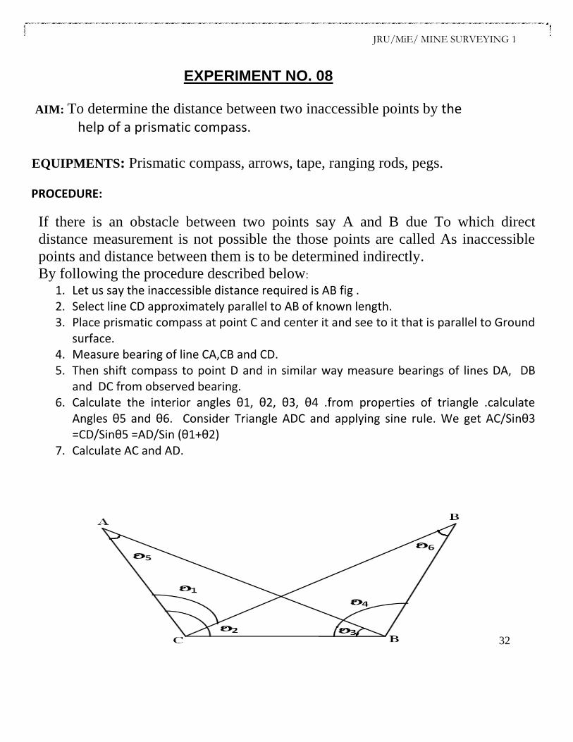
1. Let us say the inaccessible distance required is AB fig . 2. Select line CD approximately parallel to AB of known length. 3. Place prismatic compass at point C and center it and see to it that is parallel to Ground
surface. 4. Measure bearing of line CA,CB and CD. 5. Then shift compass to point D and in similar way measure bearings of lines DA, DB
and DC from observed bearing. 6. Calculate the interior angles θ1, θ2, θ3, θ4 .from properties of triangle .calculate
Angles θ5 and θ6. Consider Triangle ADC and applying sine rule. We get AC/Sinθ3 =CD/Sinθ5 =AD/Sin (θ1+θ2)
7. Calculate AC and AD.
32

JRU/MiE/ MINE SURVEYING 1
8. Link wise consider triangle BCD and apply sine rule. BC/Sin (θ3+θ4) =CD/Sinθ6
=BD/Sinθ2 BC and BD.
9. Then consider triangle ABC and apply cosine rule.
a. AB=D=√BC²+AC² - 2 X AC X BC X COSθ1. b. AB=D=√AD²+BD² -2 X AD X BD X COSθ4.
By considering triangle ABC
RESULT:
Thus the distance between two inaccessible points are calculated as -------------- by using prismatic compass.