Embed Size (px)
Citation preview

MiniRanger Plus
Technology based. Customer driven.
October 1997
Instruction Manual
PL-447
33454470Rev 2.0
mA

Thank you for purchasing Milltronics products. We endeavour to design
equipment that is simple to use and reliable in its operation, with the aim of satisfying
our customers needs.
Milltronics has been designing and manufacturing process equipment since 1954.
Our fields of expertise include ultrasonic level measurement, in-line weighing of dry
bulk solids and motion sensing.
Milltronics is established world wide through associate offices and representatives.
Our network is continually being refined to provide our customers with first rate
sales information, engineering assistance and after sales support.
For more details on our products and service, please contact us and we will provide
you with a listing of the offices or representatives nearest you.
P.O. Box 4225730 The KingswayPeterborough, ONCanada K9J 7B1
709 Stadium Drive Arlington, TexasU.S.A. 76011
Oak House Everoak EstateBromyard RoadWorcester, WR2-5HPEngland
Château de la SaurinePont de BayeuxB.P. 613590 MeyreuilAix en ProvenceFrance
Tel. (705) 745-2431Fax (705) 745-0414
Tel. (817) 277-3543Fax (817) 277-3894
Tel. (01905)748404Fax (01905) 748430
Tel. 42.65.69.00Fax 42.58.63.95

Table of Contents
General Information
About This Manual 5
About MiniRanger Plus 6
Specifications
MiniRanger Plus 7
Transducer 7
Installation
Dimensions 9
Interconnection Transducer 10
Synchronization 10
Current Output 11
Relay Output 11
Power 12
ComVerter 12
Start Up
General 15
Display & Keypad Run Mode 16
Program Mode 17
Setting Up 18
Display Messages 21
PL-447 3
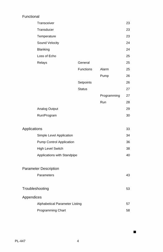
Functional
Transceiver 23
Transducer 23
Temperature 23
Sound Velocity 24
Blanking 24
Loss of Echo 25
Relays General 25
Functions Alarm 25
Pump 26
Setpoints 26
Status 27
Programming 27
Run 28
Analog Output 29
Run/Program 30
Applications 33
Simple Level Application 34
Pump Control Application 36
High Level Switch 38
Applications with Standpipe 40
Parameter Description
Parameters 43
Troubleshooting 53
Appendices
Alphabetical Parameter Listing 57
Programming Chart 58
PL-447 4

GENERAL INFORMATION
ABOUT THIS MANUAL
It is essential that this manual be referred to for proper installation and operation of your MiniRanger Plus. As MiniRanger Plus requires an STH or Echomax ultrasonictransducer to make a working system, refer to the associated transducer manual as well.
Installation gives you step by step direction for the installation and interconnection of your MiniRanger Plus.
Start Up instructs you how to operate the keypad, program and read the display.
Functional describes the functionality of the MiniRanger Plus, detailing theinteroperation of the salient features, and highlights transceiver, relay and mA operation.
Applications looks at the MiniRanger Plus from a practical point of view, using examples of the applications it is likely to encounter.
Parameters lists the parameters available to you, with a description of their function and use. You are urged to read this section; to familiarize yourself with the parameters available to you, and get your MiniRanger Plus working to its fullest.
Troubleshooting tabulates symptoms, causes and actions to common installation andapplication problems that you might encounter. Hopefully you will never have to read this section, but know it’s there to help you.
Appendices what manual would be complete without one! Ours is an alphabetical cross reference of the parameters and their numbers, and a record sheet for jotting down parameter values. Handy indeed!
GE
NE
RA
L INF
O.
PL-447 5

ABOUT MINIRANGER PLUS
MiniRanger Plus is a versatile material level monitoring instrument. Material levelmeasurement is achieved using advanced sonic echo ranging techniques. The unit iscomplete with an integral multifunction liquid crystal display, a four button keypad andan integral junction box.
Remotely coupled to an appropriate transducer, MiniRanger Plus is well suited forshort to medium range measurements of liquids or solids, in open or closed vessels.MiniRanger Plus is at home in a wide variety of industries: food, pharmaceutical,chemical, water, waste water - to name a few.
The MiniRanger Plus emits a series of ultrasonic pulses from the associatedtransducer. Each pulse is reflected as an echo from the material and sensed by thetransducer. The echo is processed by the MiniRanger using Milltronics’ proven ‘SonicIntelligence’ techniques. Filtering is applied to help discriminate between the true echofrom the material, and false echoes from acoustical and electrical noise and agitatorblades in motion. The time for the pulse to travel to the material and back istemperature compensated and then converted into distance for display, mA outputand relay actuation.
MiniRanger Plus is equipped with a two-way infrared link for compatibility withMilltronics Dolphin communication system.
MiniRanger Plus features:
multi-field LCD for: parameter, reading and bar graph display, and relay and fail-safe status.
two alarm / pump control relays
quick connect wiring terminals
high level switch operation
lead / lag pump operation
Dolphin compatibility
isolated mA output
sonic intelligence
integral keypad
GE
NE
RA
L INF
O.
PL-447 6
SPECIFICATIONS
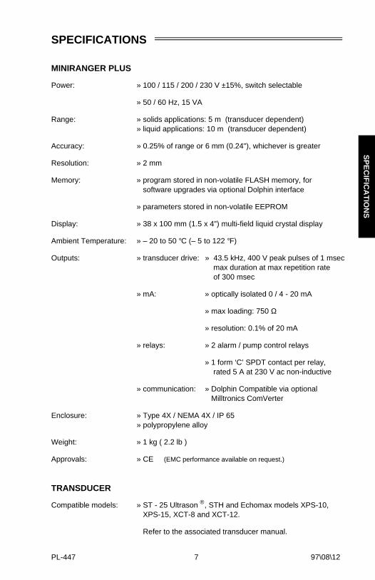
MINIRANGER PLUS
Power: » 100 / 115 / 200 / 230 V ±15%, switch selectable
» 50 / 60 Hz, 15 VA
Range: » solids applications: 5 m (transducer dependent)» liquid applications: 10 m (transducer dependent)
Accuracy: » 0.25% of range or 6 mm (0.24"), whichever is greater
Resolution: » 2 mm
Memory: » program stored in non-volatile FLASH memory, for software upgrades via optional Dolphin interface
» parameters stored in non-volatile EEPROM
Display: » 38 x 100 mm (1.5 x 4") multi-field liquid crystal display
Ambient Temperature: » – 20 to 50 °C (– 5 to 122 °F)
Outputs: » transducer drive: » 43.5 kHz, 400 V peak pulses of 1 msec max duration at max repetition rate of 300 msec
» mA: » optically isolated 0 / 4 - 20 mA
» max loading: 750 Ω
» resolution: 0.1% of 20 mA
» relays: » 2 alarm / pump control relays
» 1 form ‘C’ SPDT contact per relay, rated 5 A at 230 V ac non-inductive
» communication: » Dolphin Compatible via optional Milltronics ComVerter
Enclosure: » Type 4X / NEMA 4X / IP 65» polypropylene alloy
Weight: » 1 kg ( 2.2 lb )
Approvals: » CE (EMC performance available on request.)
TRANSDUCER
Compatible models: » ST - 25 Ultrason ®, STH and Echomax models XPS-10, XPS-15, XCT-8 and XCT-12.
Refer to the associated transducer manual.
97\08\12
SP
EC
IFIC
AT
ION
S
PL-447 7

⊗S
PE
CIF
ICA
TIO
NS
PL-447 8
INSTALLATION
This product is susceptible to electrostatic shock. Follow proper grounding procedures.
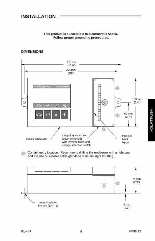
DIMENSIONS
138 mm(5.4")
sealed enclosure
270 mm(10.6")
74 mm(2.9")
254 mm(10")
integral junction box(cover removed)with terminal block andvoltage selection switch
69 mm(2.7")
mounting hole6.4 mm (1/4") Ø 5 mm
(0.2")
Conduit entry location. Recommend drilling the enclosure with a hole sawand the use of suitable cable glands to maintain ingress rating.
97\08\12
terminalblocklayout
INS
TA
LLAT
ION
PL-447 9

INTERCONNECTION
TRANSDUCER
SYNCHRONIZATION
In applications where more than one MiniRanger Plus, to a maximum of 8, are goingto be used or where their transducers are sharing a common conduit, synchronizationis required. When synchronized, no device transmits within 180 ms of the prior one(s).
To synchronize, interconnect the SYNC terminals of all devices and ensure that thereis a common electrical ground interconnecting all units.
To synchronize MiniRanger Plus with other Milltronics products, consult Milltronics oryour distributor.
transducer
Refer to transducer instruction manualfor location and mounting details.
MiniRanger Plus #1
MiniRanger Plus #2
to nextdevice
INS
TA
LLAT
ION
PL-447 10

CURRENT OUTPUT
RELAY OUTPUT
to customerinstrumentation
isolated mA output,750 Ω max load
All relays are certified for use in equipment where the short circuitcapacity of the circuits in which they are connected is limited byfuses having ratings not exceeding the rating of the relays.
com
relays shown inde-energized state,contacts rated 5 A at230 V non-inductive
n.o.
n.c.
n.c.
com
n.o.
INS
TA
LLAT
ION
PL-447 11

POWER
COMVERTER
Optional Dolphin Interface
Refer to Dolphin instruction manual for interconnection details.
MiniRanger PlusComVerter
customervoltagesupply
VOLTAGESELECT
INS
TA
LLAT
ION
PL-447 12

⊗ INS
TA
LLAT
ION
PL-447 13

⊗INS
TA
LLAT
ION
PL-447 14

START UP
GENERAL
The MiniRanger Plus has two modes of operation: run and program. When the unit is powered, after installation procedures have been completed, it is programmed tostart up in the run mode, to detect the distance from the transducer face to the targetin meters.
The unit can be placed into the program mode at any time; to alter a number ofprogram parameters in order to better suit the application or user’s preferences.Programming can be carried out via the local keypad or the optional Dolphin infrared interface.
The first step when programming is to reset all parameters to their factory setting byusing the master reset P-999. This must be done via the local keypad.
For a Quick Start, P001 to P007 are the key parameters requiring entry.
They set: - mode of measurement
- process material
- transducer type
- measurement response
- units
- empty distance
- span
There are a number of other program parameters, especially relay and mA output,that can be changed subsequently or during another programming session. Refer toParameter List for a description of the parameters available.
When programming has been completed, the MiniRanger Plus can be put into normal
operation by pressing .
typical display
ST
AR
T U
P
PL-447 15

DISPLAY and KEYPAD
Run Mode
LCD
➀ reading
➁ units
➂ high alarm indicators : = high, = high - high
➃ process material level rising or falling
➄ bar graph representation of material level, 0 to 100% of span
➅ low alarm indicators : = low, = low - low
➆ reading questionable, appears during fail-safe operation
➇ auxiliary reading
➈ relay status
➉ = normal operation = fail-safe operation
Keypad
LCD
Keypad
toggle% andunits
display temperature(auxiliary)
access program mode
display mA (auxiliary)
ST
AR
T U
P
PL-447 16

Program Mode
LCD
➀ parameter type ( transducer, relay, or mA output )
➁ reading
➂ units
➃ ‘change value’ accessed
Keypad
scrolldown
scroll up
access run mode
alternates programmode between‘select parameter’and ‘change value’functions
ST
AR
T U
P
PL-447 17

SETTING UP
To Access Program:
To Select a Parameter :
program starts at P001
run display
ST
AR
T U
P
PL-447 18

To Change a Parameter Value :
increase ordecrease to thedesired value.
if no response,security notdisabled!
save and return to ‘selectparameter’ function,
e.g. P001 = 4Must Be Pressed to Save Change!
select parameter,
e.g. P001 = 3
initiate change function
Security Must Be Disabled!
ST
AR
T U
P
PL-447 19

Express :
to jump back to P001
or
to jump to the factory setting
To Return to Run Mode
e.g. P999
Parameter
Value
jump back to P001
from the program mode
e.g. P001
exit and return torun mode
ST
AR
T U
P
PL-447 20
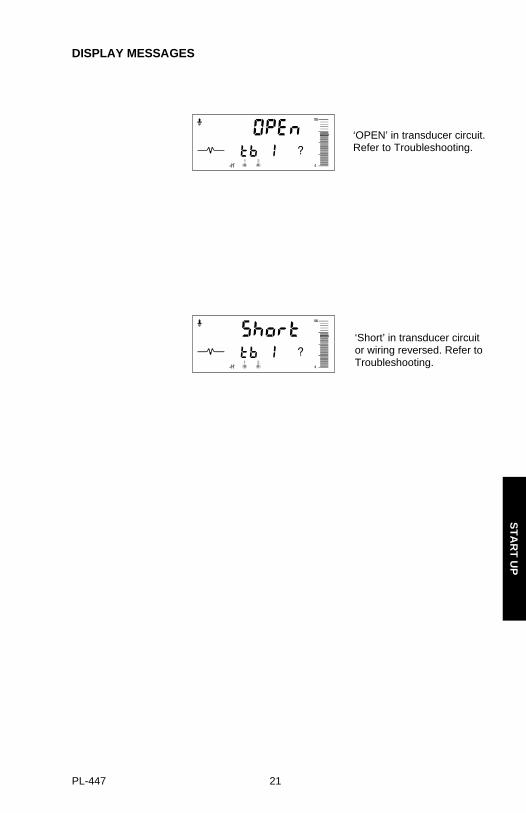
DISPLAY MESSAGES
‘OPEN’ in transducer circuit.Refer to Troubleshooting.
‘Short’ in transducer circuit or wiring reversed. Refer toTroubleshooting.
ST
AR
T U
P
PL-447 21

⊗
ST
AR
T U
P
PL-447 22

FUNCTIONAL
TRANSCEIVER
The MiniRanger Plus transceiver operates under 1 of 5 sets of preset conditions(P003), summarized as follows:
*each measurement consists of one short pulse plus the set number of long pulses.**set number of long pulses, only if required.
When a measurement is initiated, the set number of short and long pulses istransmitted. Short pulse measurements are restricted to the first 2 m range extending from the transducer face. When a short pulse is combined with a long pulse set, the short pulse range is restricted to 1 m and the long pulse covers the full measurement range.
When the echo of the transmitted pulse train is received, the relevant echo extractiontechnique (P820), is applied to determine the true material echo.
The measurement response limits the maximum rate at which the display, analogoutput and relay contacts respond to changes in measurement. It is of concernespecially where liquid surfaces are in agitation or material falls into the sound pathduring filling.
TRANSDUCER
The transducer, which is connected to the transceiver and mounted remotely at themeasurement site, converts the electrical energy of the transmit pulse into acousticalenergy and converts the acoustical energy of the echo back into electrical energy forthe transceiver receive period.
Some transducer models incorporate an integral temperature sensor. The echo andtemperature signals share the same cable wiring, then segregated at the transceiver.
parametervalue
measurementresponse
echoverification
filter fail-safetimer
long pulses*
1 0.1 m/min slow on on 100 2
2 1 m/min . on on 10 2
3 10 m/min . on on 1 2
4 100 m/min . off on 0.1 1**
5 1000 m/min fast off off 0 1**
FU
NC
TIO
NA
L
PL-447 23

TEMPERATURE
In order to compensate for uniform changes of the sound medium, temperaturesensing is achieved using a transducer with an integral sensor.
If the transducer does not have an integral sensor, temperature compensation is fixedat a programmed value, P661. The difference between the fixed value and the actualtemperature surrounding the transducer will cause an error in measurement.
SOUND VELOCITY
The MiniRanger Plus can be calibrated to compensate for sound velocity error in fixedtemperature, homogenous atmospheres.
The basis is to physically measure the level (measuring tape or sight glass) and enterthe value via P651. The MiniRanger Plus then calculates the sound velocity bycomparing the entered physical measurement to its own ultrasonic measurement.
BLANKING
Near blanking (P800) is used to ignore the zone in front of the transducer whereringdown* or other false echoes (e.g. standing wave, ladder rung) appear as an echoduring the receive cycle. This is usually indicated by an incorrect high level readingand can be overcome by increasing the near blanking from its factory set value.
* ringdown is the natural decay of transducer vibration after the transmit pulse ceases.
Far end blanking is a feature that ignores the zone below the zero or empty levelwhere false echoes can appear at levels that interfere with the processing of the true echo.
ringdown orfalse echo
true echo(level) false echo
end of transmit
0level
typical receiver signal
P-800near blanking
far endblanking
empty distance to transducerP-006
range
range extension (P-801)as % P-006
typical processed signal
FU
NC
TIO
NA
L
PL-447 24

In applications where the zero level is above the bottom of the vessel and it is desiredto monitor the zone below the normal zero, range extension (P801) can be used toextend the range into the far end blanking. Range extension is entered as a percent ofP006. As range extension reduces the protection afforded by the far end blanking, itshould be used judiciously. Avoid excessive range extension as this can reduce themeasurement’s reliability and accuracy. Range extension is factory set for 20% ofP006. If it is found that false echoes are appearing ahead of the blanking zone, P006should be reduced accordingly.
Blanking is automatically corrected for sound velocity change where temperature andvelocity compensation are used; keeping the blanking at the distance at which it is set.
LOSS OF ECHO
A loss of echo occurs when the MiniRanger Plus deems that the calculatedmeasurement is unreliable, i.e. the echo confidence (P805) is less than the threshold(P804). This can be due to such circumstances as high level of electrical noise, poorgrounding or poor transducer aiming. Refer to Troubleshooting. If the conditionpersists for a time beyond the limit as set by the fail-safe timer (P070), the confidenceicon changes from full to partial and the reading and mA output are forced to thefail-save default (P071) at the response rate (P003).
Upon receiving a reliable echo, the loss of echo condition is aborted (icon returns to full) and the reading, mA and relay output return to the present level at theresponse rate.
Relay operation responds, as programmed, to the default level as though an actualmaterial reading.
RELAYS
GENERAL
Two onboard relays are provided in the MiniRanger Plus. Each relay can be assignedone out of three functions.
FUNCTIONS
Alarm:
high alarm : occurs when the level rises to the on setpoint. The alarm is cancelled when the level reaches the off setpoint.
low alarm : occurs when the level falls to the on setpoint. The alarm is
cancelled when the level reaches the off setpoint.
highalarm
on, P112
off, P113
lowalarm
off, P113
on, P112
FU
NC
TIO
NA
L
PL-447 25

Pump:
pump down : occurs when the level rises to the on setpoint. The pump is stopped when the level reaches the off setpoint.
pump up : occurs when the level falls to the on setpoint. The pump is stopped when the level reaches the off setpoint.
pump sequencing: pumps 1 and 2 operate in lead
lag fashion alternating roles onsuccessive pump cycles (first pump on, to all pumps off) . Specifically, pump 1 responds to relay 1 and pump 2 responds to relay 2 during the first pump cycle. During the second cycle, pump 2 responds to relay 1 and pump 1 responds to relay 2.
Relays programmed for pump control will not energizewithin 10 seconds of a MiniRanger Plus power up,
or within 10 seconds of each other.
SETPOINTS
Relay setpoints are in the units as programmed (P005).
Operation, P001 = 1, 2 or 3
The setpoints are measured from the bottom up, referenced to zero or empty (P006).
Operation, P001 = 4
The setpoints are measured outward from the transducer face.
pumpdown
on, P112
pumpup
off, P113on, P112
off, P113
FU
NC
TIO
NA
L
PL-447 26

STATUS
Programming
Upon entering the program mode, the alarm relays hold their prior status, pump relaysare held off.
Relay programming: - select relay & function (P111)
- enter setpoints (P112 & P113)
•
•
•
relay 2 functione.g. 0 = off
relay 1 on setpoint
relay 2 on setpoint
relay 1 off setpoint
relay 2 off setpoint
relay 1 functione.g. 0 = off
FU
NC
TIO
NA
L
PL-447 27

Run
Fail-safe
When the fail-safe timer (P070) expires, the relays respond as follows * :
* not applicable to high level switch operation, P001 = 4. In such cases, the timer is bypassed and the mode is always ’low’.
Fail-Safe Status
Mode (P071) high alarm low alarm pump down pump up
high on off on off
low off on off on
hold hold hold hold hold
relay
alarm / pump on, e.g. relay 1
status, relay 1status, relay 2relay operational, e.g. relay 2
FU
NC
TIO
NA
L
PL-447 28

ANALOG OUTPUT
The MiniRanger Plus can be programmed to provide an analog output (P200) of 0 to20 or 4 to 20 mA, and for proportional or inverse span.
Programming
Upon entering the Program mode, the analog output level holds its prior value.
Run
The analog output responds in the following manner :
*reference value only. mA level limited by near blanking.
0 and 100% are percentage of full scale reading (m, cm, mm, ft, in)
Level
Space
Distance
orH. L. S.
FU
NC
TIO
NA
L
PL-447 29

Fail-safe
When the fail-safe timer (P070) expires, the mA output responds as follows * :
* not applicable to high level switch operation, P001 = 4. In such a case, the measurement immediately defaults to a low value.
RUN / PROGRAM
When the MiniRanger Plus changes from run to program, the transceiver stopsoperating and the last measurement is stored; the associated reading, alarm statusand mA output are held (pump control relays are turned off). As a courtesy, the unitreverts to the parameter last addressed during the previous program session. Duringprogram, the unit does not respond to the process unless the calibration parameters(P650 and P651) are accessed. If the calibration parameters are accessed, onlythe reading becomes responsive.
Upon return to run, the transceiver resumes operation. The reading and associatedoutputs default to the last measurement taken, either during the previous run sessionor as a result of having accessed a calibration parameter. The reading and associatedoutputs migrate to the current process level at a rate controlled by the measurementresponse (P003).
Fail-safe Mode(071)
Status
0/4 – 20 20 – 0/4
high 20 0/4
low 0/4 20
hold hold hold
FU
NC
TIO
NA
L
PL-447 30

⊗F
UN
CT
ION
AL
PL-447 31

⊗
FU
NC
TIO
NA
L
PL-447 32

APPLICATIONS
This section highlights the most common applications to which the MiniRanger Plus islikely to be applied. Other applications not described here, such as position monitoringof a piston on a wood pulverizer, are basically improvisational and imaginative ways ofapplying the MiniRanger Plus. The trick is knowing the parameters available to you,and their limitations. Refer to Parameter Description.
When programming, refer to the application which is most similar to yours. A practicalexample has been given to further expand on the programming features. As theexample may not completely cover your application, again, it is important that youfamiliarize yourself with the list of available parameters.
The minimum distance from the transducer face to the target is limited by the minimum range of the transducer connected.
AP
PLIC
AT
ION
S
PL-447 33

SIMPLE LEVEL APPLICATIONOne of the most common applications of a Milltronics process material level monitor issimple level measurement, whereby the material level or space between thetransducer and reflecting surface is measured and displayed. This may or may notinclude alarms and mA output.
Example
The application is to obtain a level measurement and corresponding 4-20 mA outputproportional to material level in a gravel bin. The transducer face is 5 m from the binbottom. The empty level is 0 m (bottom) and the full level (span) is 4.5 m from thebottom. A high alarm is required at 4 m from the bottom and a low alarm is required at1 m from the bottom. The maximum rate of filling or emptying is about 1 m/min. In theevent of a loss of echo, the MiniRanger Plus is to go into fail-safe low after 2 min.
reset:
P999 master reset
program:
P001 enter ’1’ mode of measurement = level
P002 enter ’2’ material = solids
Span(P007)
Empty(P006)
P112-2 1.0 m
P113-2 1.1 m
P113-13.9 m
P112-14.0 m
offon
onoff
relay 2
relay 1
AP
PLIC
AT
ION
S
PL-447 34

P003 enter ‘2’ measurement response = 1 m/min.
P004 enter ‘102’ the transducer model purchased with this system is an XPS-10
P005 enter ‘1’ units = metres
P006 enter ‘5’ empty distance = 5 m
P007 enter ‘4.5’ span = 4.5 m
P070 enter ‘2’ fail-safe timer = 2 min
P071 enter ‘2’ fail-safe = low
P111-1 enter ‘1’ level alarm, relay 1
P111-2 enter ‘1’ level alarm, relay 2
P112-1 enter ‘4’ relay 1, on setpoint = 4 m
P112-2 enter ‘1’ relay 2, on setpoint = 1 m
P113-1 enter ‘3.9’ relay 1, off setpoint = 3.9 m (nominal value, 0.1 m deadband)
P113-2 enter ‘1.1’ relay 2, off setpoint = 1.1 m (nominal value, 0.1 m deadband)
P200 enter ‘2’ mA output = 4 - 20
run: press run to start normal operation
AP
PLIC
AT
ION
S
PL-447 35

PUMP CONTROL APPLICATIONThe basic difference between a simple level application and a pump controlapplication is that the relays assigned to pump function (P111) are normallyde-energized (off) and energized when required to run the pump. In the programmode, pump relays are held de-energized.
Pumps can be programmed to work independently or in lead/lag fashion. Refer toFunctional \ Relays \ Functions.
In applications where flooding is possible, a submersible transducer should be used.The submersible transducer’s air cavity insures that a high level reading is maintainedrather than establishing a loss of echo condition, when the liquid level reaches thetransducer. When using a submersible transducer, set P802 = 1.
Example
The application is to control the level in a wet well. It is required that the level bedisplayed in centimetres. The transducer is mounted at 3.6 m from the bottom and isequipped with a submergence coupling as there is possibility of flooding in the well.Two pumps are to be controlled by the MiniRanger Plus in lead / lag fashion. The firstpump to start at 1 m and the second pump to start at 2 m. Both pumps are to stop at0.25 m. The maximum estimated filling rate is 1 m/min. In the event of a loss of echo,a fail-safe low after 6 sec is required to protect the pumps from running dry.
reset:
P999 master reset
program:
P001 enter ‘1’ mode of measurement = level
P002 enter ‘1’ material = liquids
P0063.6 m
P0073.0 m
P112-1, 2 m
P112-2, 1 m
P113-1 & 2, 0.25 m
relay 1,pump on
relay 2,pump on
relay 1 & 2pumps off
AP
PLIC
AT
ION
S
PL-447 36

P003 enter ‘2’ measurement response = 1 m / min
note: the associated preset fail-safe timer is 10 minutes. Override this value by setting P070.
P004 enter ‘102’ the transducer model purchased with this system is an XPS-10
P005 enter ‘1’ units = metres
P006 enter ‘3.6’ empty distance = 3.6 m
P007 enter ‘3’ span = 3 m
P070 enter ‘.1’ fail-safe timer = 6 sec (0.1 min)
P111-1 enter ‘3’ relay 1 function = 3, pump sequencing
P111-2 enter ‘3’ relay 2 function = 3, pump sequencing
P112-1 enter ‘2’ relay 1, on setpoint = 2 m
P112-2 enter ‘1’ relay 2, on setpoint = 1 m
P113-1 enter ‘.25’ relay 1, off setpoint = 0.25 m (nominal value, 0.1 m deadband)
P113-2 enter ‘.25’ relay 2, off setpoint = 0.25 m (nominal value, 0.1 m deadband)
P802 enter ‘1’ submergence = on
run: press run to start normal operation
AP
PLIC
AT
ION
S
PL-447 37

HIGH LEVEL SWITCHThe MiniRanger Plus can be programmed as a high level switch. Significantdifferences between this and other modes of operation are :
- the fail-safe function (P070 and P071) is effectively disabled
- on loss of echo, the measurement immediately defaults to a low value (P006)
- relay setpoints are measured from the face of the transducer
- the reading is distance from the face of the transducer to the material
A high level switch application is primarily used to detect a high level condition. Assuch, aim the transducer so that it is perpendicular to the material angle of repose atthe alarm level when filling.
Example
A high level switch is required in a corn silo when the material comes within 1 m of thetransducer face. The maximum filling rate is 0.2 m / min.
reset:
P999 master reset
program:
P001 enter ‘4’ mode of measurement = high level switch
P002 enter ‘2’ material = solids
P113, 2 m
P112, 1m
AP
PLIC
AT
ION
S
PL-447 38

P003 enter ‘2’ measurement response = 1 m/min
note: this is the next fastest response rate that would satisfy the given maximum filling rate
P004 enter ‘104’ the transducer model purchased with this system is an XPS-15
P005 enter ‘1’ units = metres
P006 enter ‘4’ empty distance = 4 m (nominal value)
P007 enter ‘4’ span = 4 m (nominal value)
P111-1 enter ‘1’ level alarm, relay 1
P112-1 enter ‘1’ relay 1, on setpoint = 1 m
P113-1 enter ‘2’ relay 1, off setpoint = 2 m (nominal value, 0.1 m deadband)
run: press run to start normal operation
AP
PLIC
AT
ION
S
PL-447 39

APPLICATIONS WITH STANDPIPEIn many liquid applications, access to the vessel must be made via a standpipe. In such cases, Milltronics can provide optional flanged transducers, or split flangesthat mate to a flanged standpipe. Another option is to hang the transducer from ablind flange.
The standpipe length should be as short and the diameter as large as possible. As arule of thumb, the –3 dB cone of the sound beam should not intersect the standpipewall in applications opening into a vessel. Otherwise, additional near blanking (P800)is required to compensate for the interference zone created by the opening.
transducer radiating face
no additionalblanking required
nointersection
vesseltransducer
sound beamintersectspipewall
vesselreflection at interferencezone created by opening
near blanking extension of 150mm (6") past end of standpipe
may be required
no vessel
no additionalblankingrequired
AP
PLIC
AT
ION
S
PL-447 40

⊗A
PP
LICA
TIO
NS
PL-447 41

⊗
AP
PLIC
AT
ION
S
PL-447 42

PARAMETER DESCRIPTION
P000 lock
Locks out the programming ’change value’ function such that the values of P001 through P999 cannot be changed. This however does not prevent the ‘select’ function from use for viewing values. Programming is locked out if the value of P000 is other than 1954.
entry : 1954 = unlocked
1954 = locked
P001 operation
Determines the mode of measurement.
entry : 1 = level; material level referenced to empty distance (P006)
2 = space; space to material level referenced from zero span
3 = distance; distance to target referenced from the transducer face
4 = high level switch (h.I.s.)
P002 material
Optimizes measurement reliability for target type.
entry : 1 = liquids, fluids or flat surfaces
2 = irregular surfaces and solids
Level (P001 = 1) Space (P001 = 2) Distance (P001 = 3)or
H.L.S. (P001 = 4)
PA
RA
ME
TE
R D
ES
C.
PL-447 43

P003 measurement response
Collectively sets a number of operating parameters that determine the maximum rate of change in target range that the reading, alarm and mA output functions can keep up to.
If MiniRanger Plus cannot keep up with the rate of level change, select a faster rate. If the reading bounces around an average value, select a slower rate. In general, reliability is traded for speed. Noisy applications or those with agitators tend to be more reliable at a slower response rate, as they make use of filtering, echo verification and longer fail-safe delay.
Select P003 for a measurement response just faster than the greater of the maximum filling or emptying rate.
echo verification: discriminates between agitator blades in motion or spurious noise, and the target surface (true echo).
filter: discriminates between false echoes from constant acoustical or electrical noise, and the target surface.
fail-safe timer: establishes the period from the time a loss of echo starts until the fail-safe default (P071) is effected. The P003 preset timer value can be overridden by P070.
long pulses: sets the number of long pulses to be fired during the course of a measurement. Reliability (2) is traded for speed (1).
entry:
* fail-safe function is disabled for high level switch operation, P001 = 4.
P004 transducer
Identifies transducer model connected.
entry : 1 = ST-25 102 = XPS-10
100 = ST-H 103 = XCT-12
101 = XCT-8 104 = XPS-15
measurementresponse
echoverification filter
f-s timer*(P070)
longpulses
1 = 0.1 m/min (slow) on on 100 2
2 = 1 m/min . on on 10 2
3 = 10 m/min . on on 1 2
4 = 102 m/min / 1.7 m/sec . off on 0.1 1
5 = 1020 m/min / 17 m/sec (fast) off off 0 1
PA
RA
ME
TE
R D
ES
C.
PL-447 44

P005 units
Determines the units for programming and measurement.
entry : 1 = metres
2 = centimetres
3 = millimetres
4 = feet
5 = inches
P006 empty
Distance from transducer face to empty level or maximum target range.
P007 span
Distance from empty (P006) to full / 100% level or minimum target range.
P070 fail-safe timer
The amount of time delay, in minutes, before going into fail-safe mode.
Disabled for h.I.s. operation (P001 = 4)
P071 fail-safe material level
Selects the default measurement in the event that the fail-safe timer expires.
entry : 1 = high; maximum span value
2 = low; minimum span value
3 = hold; hold current value
Disabled for h.I.s. operation (P001 = 4)
PA
RA
ME
TE
R D
ES
C.
PL-447 45
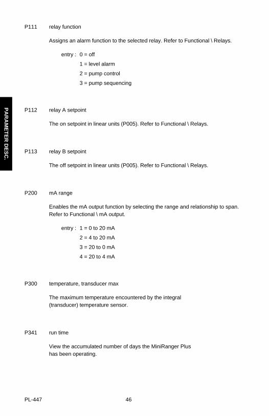
P111 relay function
Assigns an alarm function to the selected relay. Refer to Functional \ Relays.
entry : 0 = off
1 = level alarm
2 = pump control
3 = pump sequencing
P112 relay A setpoint
The on setpoint in linear units (P005). Refer to Functional \ Relays.
P113 relay B setpoint
The off setpoint in linear units (P005). Refer to Functional \ Relays.
P200 mA range
Enables the mA output function by selecting the range and relationship to span. Refer to Functional \ mA output.
entry : 1 = 0 to 20 mA
2 = 4 to 20 mA
3 = 20 to 0 mA
4 = 20 to 4 mA
P300 temperature, transducer max
The maximum temperature encountered by the integral (transducer) temperature sensor.
P341 run time
View the accumulated number of days the MiniRanger Plus has been operating.
PA
RA
ME
TE
R D
ES
C.
PL-447 46

P650 offset calibration
Typically used to calibrate the ultrasonic measurement, and its associated outputs, to a known value.
- fill the tank as much as permissible, without going into the near blanking.
- monitor P650 until a stable reading is obtained.
- (to access change function).
- scroll the value to the actual level, space or distance respective to the mode of measurement (P001).
- (to validate entry). The MiniRanger Plus calculatesthe measurement offset to be applied to the reading.
P651 sound velocity calibration
Provides sound velocity compensation on an empty tank. This is typically required on an application where the atmosphere in the tank is a homogenous gas or vapour other than air.
- empty the tank as much as permissible. Leave filled with normal vapour and normal operating temperature.
- monitor P651 until a stable reading is obtained.
- (to access change function).
- scroll value to the actual level, space or distance respective to the mode of measurement (P001).
- (to validate entry). The MiniRanger Plus calculatesthe new sound velocity for measurement correction.
P740 peripherial communication Not supported by the associated product.
P661 temp fixed
For use with ST-25 Ultrason® transducers. As these transducers do not havean integal temperature sensor a nominal value representing the ambient temperature of the transducer must be entered. If the temperature between the transducer and the target varies, enter the average temperature.
PA
RA
ME
TE
R D
ES
C.
PL-447 47

P800 near blanking
Sets the amount of blanking as measured from the transducer face and extending into the measurement range. Refer to Functional\Blanking.
enter value referenced from the face of the transducer in units of P005.
P801 range extension
Sets the amount of range extension as measured from the empty distance (P006) and extending into the far end blanking. Refer to Functional\Blanking.
enter as a % of P006, the distance below empty not blanked.
P802 submergence transducer
When using a submergence transducer, set entry to ‘1’ to enable submergence feature. Refer to Applications \ Pump Control Application.
entry : 0 = normal
1 = submersible
P804 confidence threshold
The minimum echo confidence in dB that either the short or long echo must meet in order to prevent a loss of echo condition and the expiration of the fail-safe timer (P070).
short minimum echo confidence for short pulse echoes; those within the short pulse echo range.
long minimum echo confidence for long pulse echoes.
entry : ## : ## = short : long
P805 echo confidence
A measure of echo reliability.
display : ## : ## = short : long
where : ## = 0 to 99 ; confidence value
run mode :
PA
RA
ME
TE
R D
ES
C.
PL-447 48

P806 echo strength
The absolute strength of the selected echo, in dB above 1 uV rms.
run mode :
P807 noise
The peak and average ambient noise, in dB above 1 uV rms.
Ambient noise includes acoustical and electrical noise being picked up by thetransducer / receiver circuit while in the program mode (transmit disabled).
display : ## : ## = average : peak
run mode:
P820 algorithm
Selects the algorithm to be applied to the echo profile in order to extract the true echo.
entry : 1 = best of first and largest
2 = first echo
3 = largest echo
P830 TVT type
Selects the TVT profile applied to the echo profile.
entry : 1 = standard
2 = flat (typically; may yield higher confidences on some solids applications)
P900 software revision
Displays the EPROM software revision level.
96\07\22
PA
RA
ME
TE
R D
ES
C.
PL-447 49

P901 memory
Tests the memory. Test is initiated by scrolling to the parameter or repeated by .
display : PASS = normal
FAIL = consult Milltronics
P907 programmer interface
Tests the infrared communication link. Test is initiated by scrolling to the parameter or repeated by .
display : PASS = normal
FAIL = consult Milltronics
P910 relay
Tests the alarm relays.
entry : 0 = de-energizes selected relay
1 = energizes selected relay
P911 mA output value
Displays the value from the previous measurement. A test value can be entered and the displayed value is transmitted to the output. Upon returning to the run mode, the parameter assumes the actual mA output level.
infrared communication link
mirror
MiniRanger Plus
PA
RA
ME
TE
R D
ES
C.
PL-447 50

P923 distance measurement
The reading corresponding to the distance between the material level and the transducer face.
run mode
P999 master reset
Resets parameters to their factory setting.
PA
RA
ME
TE
R D
ES
C.
PL-447 51

⊗
PA
RA
ME
TE
R D
ES
C.
PL-447 52

TROUBLESHOOTING
The following is a list of operating symptoms, their probable causes and the actionsneeded to resolve them.
SYMPTOM CAUSE ACTION
Loss of echo
display reads ‘Short’,no pulsing is felt on thetransducer face
short circuit or reverse wiring
defective transducer
check transducer wiring*
check maximumtemperature P300 againsttransducer rating*
try substitute
display reads ‘OPEN’, nopulsing is felt on thetransducer face
open circuit
defective transducer orcircuit board
check transducer wiring*
check maximumtemperature P300 againsttransducer rating*
try substitute
display reads pulsing is felt ontransducer face
level or target is out ofrange
application too dusty orsteamy, under theseconditions range can beadversely affected
material build-up ontransducer face
check transducerspecifications*
check calibrationparameters
re-aim transducer*
use foam faced transducerfor dusty applications*.
try using a longer rangetransducer
increase fail-safe timer,P070
clean
move transducer to betterlocation*
mount in standpipe*
* refer to associated transducer manual
TR
OU
BLE
SH
OO
TIN
G
PL-447 53

SYMPTOM CAUSE ACTION
. . . continued transducer location oraiming :- poor installation- moved by material or vibration- flanging not level
transducer malfunction :- temperature too high - physical damage- excessive foam on liquid face
re-locate or re-aimtransducer for maximumecho confidence, P805
check P300, P805, P807
inspect
use foam deflector orstilling well or relocate
Reading does not change,but the level does
MiniRanger Plusprocessing wrong echo, i.e. vessel wall, structuralmember, stationaryagitator, material hang-upor rat-hole
transducer ringdown,reading high level
re-aim transducer*
check standpipe forinternal burrs or welds
mounting need only behand tight*
increase blanking, P800
raise short measurementconfidence threshold, P804
Measurement isconsistently off by aconstant amount
measurement offset refer to P650
Reading errorprogressively worsens with distance
atmosphere other than airor stratified
refer to P651
Screen blank loss of power check voltage selectorswitch
check power wiring
* refer to associated transducer manual
TR
OU
BLE
SH
OO
TIN
G
PL-447 54

SYMPTOM CAUSE ACTION
Reading erratic echo confidence weak,
liquid surface agitated,
material filling
refer to P805,P807
decrease measurementresponse P003
enable filter, echoverification
relocate transducer*
electrical noise
agitator blades
check P-807 underquiescent conditions, noiseshould be under 15 dB
transducer cable must bein grounded metal conduitand cable grounded onlyat TB-1*
enable echo verification,P003
Reading ‘EEEE’ reading too large re-calibrate
Reading response slow P003 setting increase response ifpossible
Reads correctly butoccasionally reads highwhen vessel is not full
detecting close range echoor ringdown
increase blanking
increase shortmeasurement threshold,P804
transducer mounting*
High level reading lowerthan material level
material is within nearblanking zone
echo multiple beingprocessed
decrease blanking P800(limit to transducer minrange*) or raise transducer
* refer to associated transducer manual
TR
OU
BLE
SH
OO
TIN
G
PL-447 55

⊗
TR
OU
BLE
SH
OO
TIN
G
PL-447 56

APPENDICES
Alphabetical Parameter List
algorithm P820 submergence transducer P802
confidence threshold P804 temperature fixed P661
distance measurement P923 temperature, transducer max P300
echo confidence P805 transducer P004
echo strength P806 TVT type P830
empty P006 units P005
fail-safe material level P071
fail-safe timer P070
lock P000
mA output value P911
mA range P200
master reset P999
material P002
measurement response P003
memory P901
near blanking P800
noise P807
offset calibration P650
operation P001
peripheral comm. P740 *
programmer interface P907
range extension P801
relay P910
relay A setpoint P112
relay B setpoint P113
relay function P111
run time P341
software revision P900
sound velocity calibration P651
span P007
* communication not supported by the associated product.
AP
PE
ND
ICE
S
PL-447 57

96/03/22
PROGRAMMING CHARTPARAMETER
# NAME VALUE
P001 Operation
P002 Material
P003 Measurement Response
P004 Transducer
P005 Units
P006 Empty
P007 Span
P070 Fail-safe Timer
P071 Fail-safe Material Level
P111-1 Relay Function
P111-2 Relay Function
P112-1 Relay A Setpoint
P112-2 Relay A Setpoint
P113-1 Relay B Setpoint
P113-2 Relay B Setpoint
P200 mA Range
P300 Temp. Tranducer Max
P341 Run Time
P650 Offset Calibration
P651 Sound Velocity Calibration
P661 Temperature, Fixed
P740 Peripheral communication*
P800 Near Blanking
P801 Range Extension
P802 Submergence Transducer
P804 Confidence Threshold
P820 Algorithm
P830 TVT Type
P923 Distance Measurement
* communication not supported by the associated product
AP
PE
ND
ICE
S
PL-447 58