Embed Size (px)
Citation preview
MINISTRY OF POWERGovernment of India
New Initiative on Material Mobilisation Report of Committee A
1
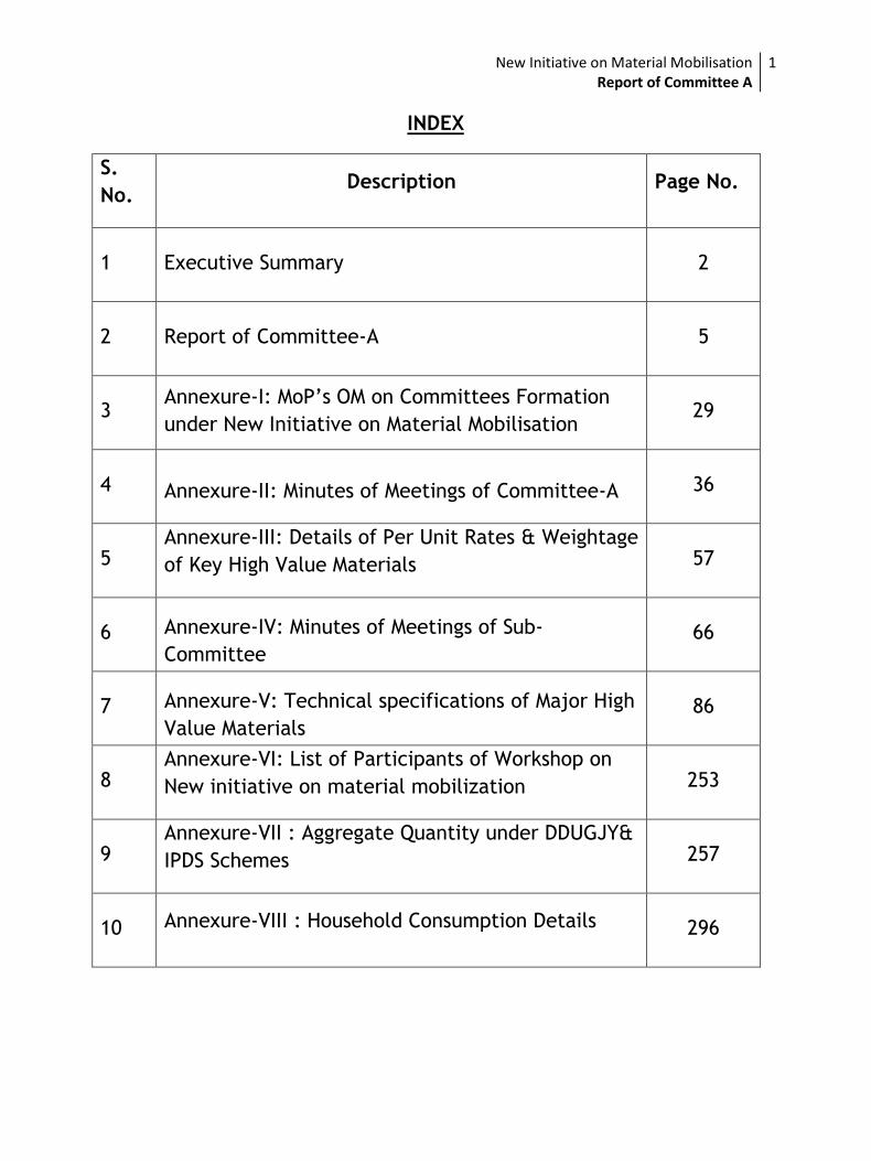
INDEX
S.
No. Description Page No.
1 Executive Summary 2
2 Report of Committee-A 5
3 Annexure-I: MoP’s OM on Committees Formation
under New Initiative on Material Mobilisation 29
4 Annexure-II: Minutes of Meetings of Committee-A 36
5 Annexure-III: Details of Per Unit Rates & Weightage
of Key High Value Materials 57
6 Annexure-IV: Minutes of Meetings of Sub-
Committee 66
7 Annexure-V: Technical specifications of Major High
Value Materials 86
8 Annexure-VI: List of Participants of Workshop on
New initiative on material mobilization 253
9 Annexure-VII : Aggregate Quantity under DDUGJY&
IPDS Schemes 257
10 Annexure-VIII : Household Consumption Details 296
New Initiative on Material Mobilisation Report of Committee A
2
Executive Summary
New Initiative on Material Mobilisation Report of Committee A
3
Executive Summary
Ministry of Power (MoP) vide OM No. 44/30/2015-RE dated 14.08.2015
constituted two committees to facilitate and handhold States for mobilizing
major material/equipment with Standard Technical Specification at
competitive prices through a transparent bidding process under DDUGJY &
IPDS. Committee-A, headed by the Chairperson, CEA, was entrusted with the
task of listing out major equipment/ material, finalize technical specifications,
aggregate requirement of various states and undertake vendor empanelment.
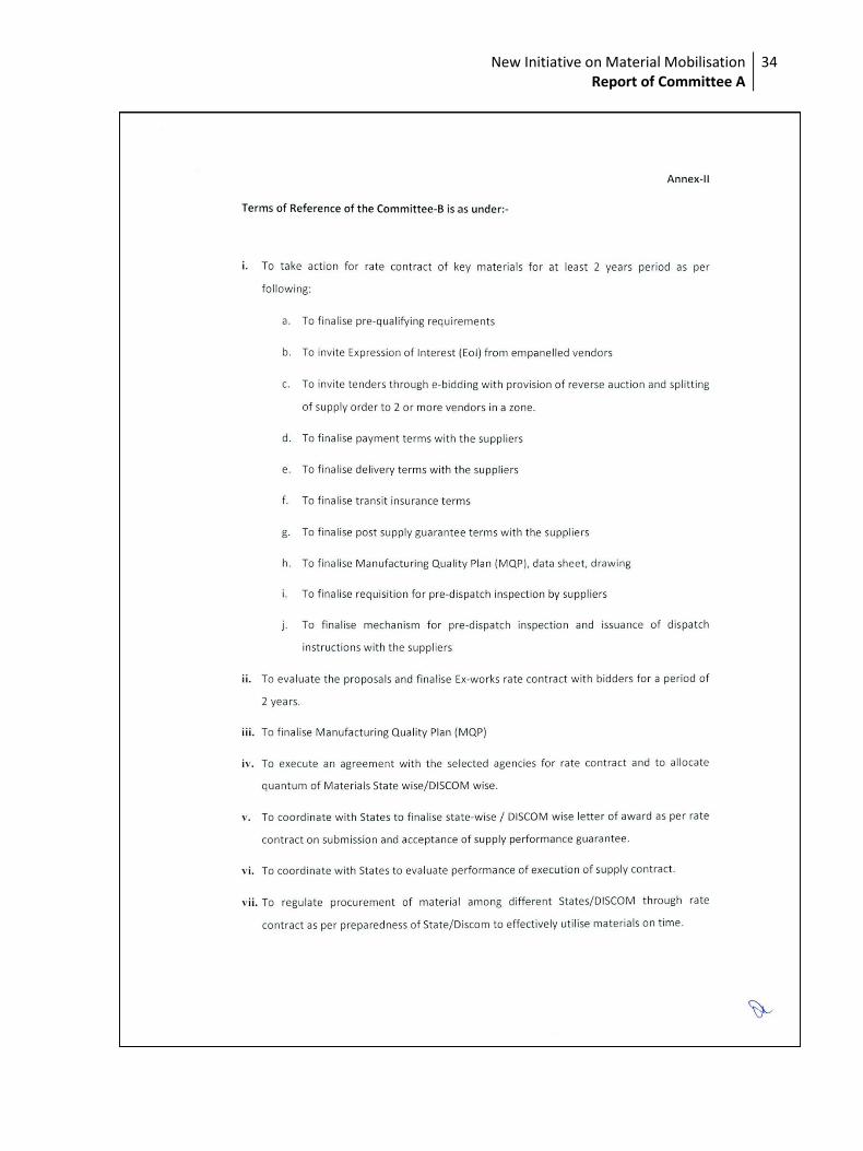
Committee B, headed by Director (Projects) PGCIL, was entrusted to prepare
bidding documents, carry out bid processing through e-tendering under reverse
bidding mode, evaluate bids and finalize rate contracts.
Committee A deliberated on various tasks assigned to it during 4 meetings held
on 22nd Aug. 2015, 28th Aug. 2015, 07th Sept. 2015 and 18th Sept. 2015. Besides,
a sub-committee under GM, PGCIL was also constituted to finalize the technical
specifications of high value items. The sub-committee hold 3 meetings to
finalize the technical specifications. A two day workshop with the
representative of states was also held to finalize the quantities of high value
items.
The Committee observed that empanelment of vendors being a complex task
requires finalization of pre-qualification requirements, inviting Request for
Empanelment and evaluation of the proposals involving large number of
vendors. To carry out this process, the laid down procedures of tendering and
mandatory provisions of CVC are to be complied which will require a time more
than 3 weeks given to the Committee A. Further, this activity needs setting up
of a dedicated cell. It was also noted that the activity of empanelment and
finalization of rate contracts are inter-related with the scope of Committee B.
Therefore, in consultation with Ministry of Power (MoP), it was decided that
the Committee B may be entrusted with responsibility of empanelment of
vendors. Hence, Committee ‘A’ has deliberated on the task (i) to (iv) of ToR.
The Committee A deliberated in detail on finalization of high value items out of
the sanctioned cost of IPDS/DDUGJY, their technical specifications and
finalization of quantities of all high value items included in DDUGJY/IPDS.
Major High value materials, which contribute around 80% supply cost of sub
transmission and distribution projects under DDUGJY/IPDS schemes, were
considered while finalization of the list of major high value materials. Further,
two strategies were adopted for finalization of high value item viz. calculation
of %age share of various materials in per unit quantity and calculation of %age
of major high value material from the DPRs of DDUGJY/IPDS. Based on the
analysis & discussion, the major high value materials finalized by the
New Initiative on Material Mobilisation Report of Committee A
4
committee are Power transformers, Distribution Transformer, all type of
Conductor, AB cable, UG Cable and Energy Meter.
The Standard Technical Specifications for major high value materials were
already provided in Standard Bidding Documents (SBD) for DDUGJY & IPDS
schemes, which are approved by Monitoring Committee. However, based on
comments received from IEEMA/ITMA & committee members, the technical
specifications were revisited by a sub-committee formulated under leadership
of GM (QA), PGCIL and the finalized technical specifications are attached in the
report. The various issues raised by IEEMA/ITMA regarding use of Amorphous
core transformer, copper wound transformers and use of in build LT breaker in
distribution transformers have also been discussed while finalizing the
technical specification of distribution transformers.
The task regarding assessment of aggregating quantity was a complex issue due
to change in submitted and approved quantities of projects under DDUGJY and
IPDS schemes. Therefore, keeping in view the time constraints, a workshop was
organized on 12th& 13th Sep 2015 at New Delhi with nodal officers of states
utilities to finalize the quantities under DDUGJY/IPDS which was attended by
55 representatives of 32 utilities. Efforts were also made to consolidate the
quantity of major materials under all sub-transmission & distribution schemes
in States other than DDUGJY/IPDS like schemes under State Plan, schemes
funded under World Bank/JICA etc. However, during workshop, State
representatives informed that other schemes funded by other funding agencies
like JICA/World Bank etc have their own agreed methodology for procurement.
Hence, the States expressed their unwillingness to include those requirements
under this initiative of centralized finalization of rate contract.
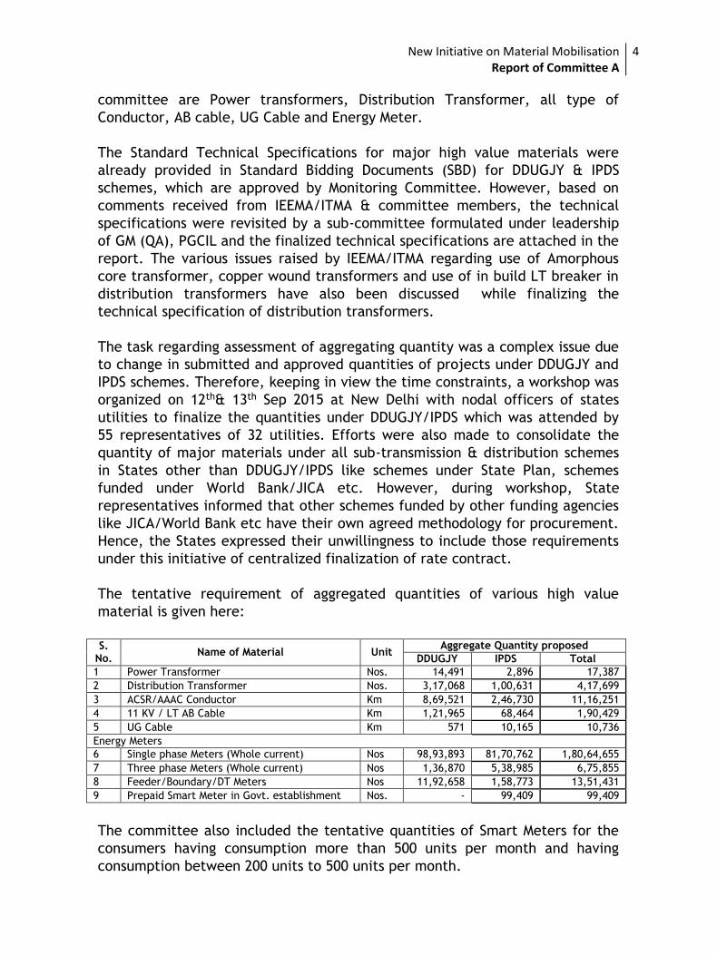
The tentative requirement of aggregated quantities of various high value
material is given here:
S.
No. Name of Material Unit
Aggregate Quantity proposed
DDUGJY IPDS Total
1 Power Transformer Nos. 14,491 2,896 17,387
2 Distribution Transformer Nos. 3,17,068 1,00,631 4,17,699
3 ACSR/AAAC Conductor Km 8,69,521 2,46,730 11,16,251
4 11 KV / LT AB Cable Km 1,21,965 68,464 1,90,429
5 UG Cable Km 571 10,165 10,736
Energy Meters
6 Single phase Meters (Whole current) Nos 98,93,893 81,70,762 1,80,64,655
7 Three phase Meters (Whole current) Nos 1,36,870 5,38,985 6,75,855
8 Feeder/Boundary/DT Meters Nos 11,92,658 1,58,773 13,51,431
9 Prepaid Smart Meter in Govt. establishment Nos. - 99,409 99,409
The committee also included the tentative quantities of Smart Meters for the
consumers having consumption more than 500 units per month and having
consumption between 200 units to 500 units per month.
New Initiative on Material Mobilisation Report of Committee A
5
Report
of
Committee-A
New Initiative on Material Mobilisation Report of Committee A
6
Report of Committee-A
on
New Initiatives on Material Mobilization
Background:
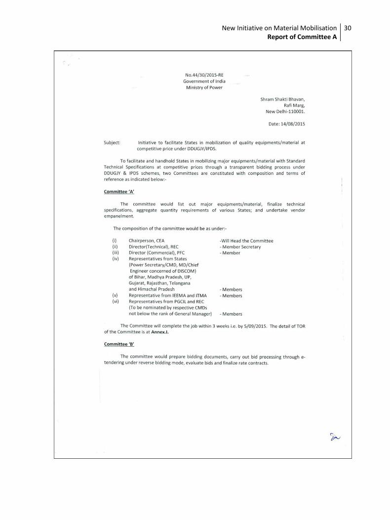
Ministry of Power (MoP) vide their OM No. 44/30/2015-RE dated 14.08.2015
constituted two committees to facilitate and handhold States for mobilizing
major material/equipment with Standard Technical Specification at
competitive prices through a transparent bidding process under DDUGJY &
IPDS. Committee-A headed by the Chairperson, CEA was entrusted to list out
major equipment/ material, finalize technical specifications, aggregate
requirement of various states and undertake vendor empanelment. Committee
B headed by Director (Projects) PGCIL was entrusted to prepare bidding
documents, carry out bid processing through e-tendering under reverse bidding
mode , evaluate bids and finalize rate contracts.
The Copy of OM of MoP is at Annexure-I.
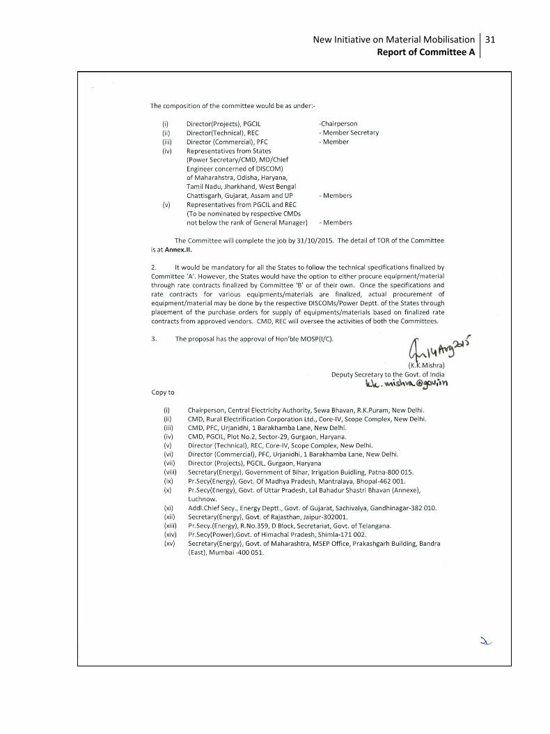
Composition of Committee A:
As per OM, the composition of committee A is as under:
i. Chairperson, CEA - Head of the Committee
ii. Director (Technical), REC - Member Secretary
iii. Director (Commercial), PFC - Member
iv. Representatives from States - Members
(Bihar, MP, UP, Gujarat, Rajasthan,
Telangana & Himachal Pradesh)
v. Representative from IEEMA & ITMA - Members
vi. Representatives from PGCIL & REC - Members
(To be nominated by respective CMDs
not below the rank of General Manager)
New Initiative on Material Mobilisation Report of Committee A
7
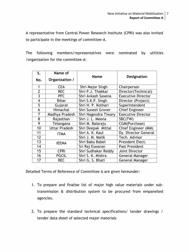
A representative from Central Power Research Institute (CPRI) was also invited
to participate in the meetings of committee-A.
The following members/representatives were nominated by utilities
/organization for the committee-A:
S.
No.
Name of
Organization /
State
Name Designation
1 CEA Shri Major Singh Chairperson
2 REC Shri P.J. Thakkar Director(Technical)
3 PFC Shri Avkash Saxena Executive Director
4 Bihar Shri S.K.P. Singh Director (Project)
5 Gujarat Shri H. P. Kothari Superintendent
Engineer 6 Himachal
Pradesh
Shri Suneel Grover Chief Engineer
7 Madhya Pradesh Shri Nagendra Tiwary Executive Director
8 Rajasthan Shri J. L. Meena SBC(TW)
9 Telangana Shri M. Balaraju CGM(Purchase)
10 Uttar Pradesh Shri Deepak Mittal Chief Engineer (MM)
11 ITMA Shri A. K. Kaul Dy. Director General
12 Shri J. M. Malik Tech. Advisor
13 IEEMA Shri Babu Babel President Elect.
14 Sri Raj Eswaran Past President
15 CPRI Shri Sudhakar Reddy Joint Director
16 PGCIL Shri S. K. Mishra General Manager
17 REC Shri G. S. Bhati General Manager
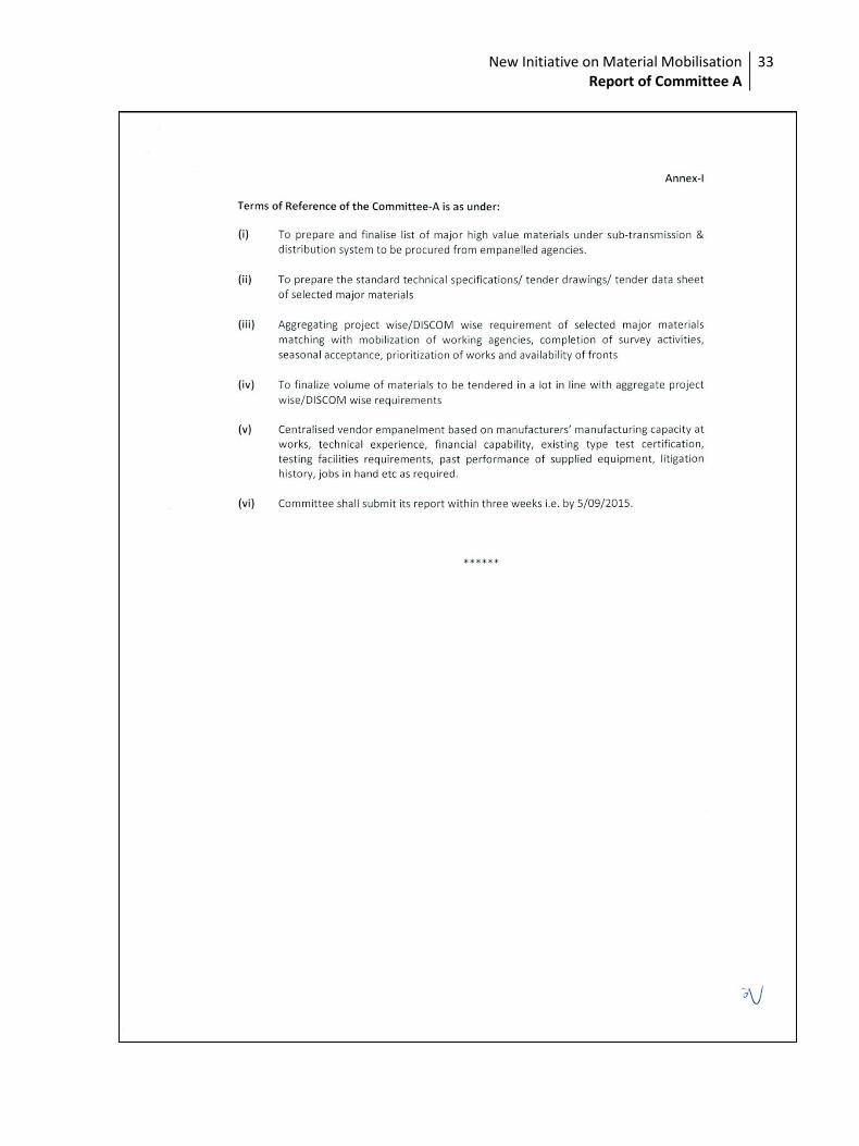
Detailed Terms of Reference of Committee A are given hereunder:
1. To prepare and finalise list of major high value materials under sub-
transmission & distribution system to be procured from empanelled
agencies.
2. To prepare the standard technical specifications/ tender drawings /
tender data sheet of selected major materials
New Initiative on Material Mobilisation Report of Committee A
8
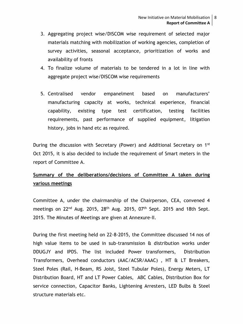
3. Aggregating project wise/DISCOM wise requirement of selected major
materials matching with mobilization of working agencies, completion of
survey activities, seasonal acceptance, prioritization of works and
availability of fronts
4. To finalize volume of materials to be tendered in a lot in line with
aggregate project wise/DISCOM wise requirements
5. Centralised vendor empanelment based on manufacturers’
manufacturing capacity at works, technical experience, financial
capability, existing type test certification, testing facilities
requirements, past performance of supplied equipment, litigation
history, jobs in hand etc as required.
During the discussion with Secretary (Power) and Additional Secretary on 1st
Oct 2015, it is also decided to include the requirement of Smart meters in the
report of Committee A.
Summary of the deliberations/decisions of Committee A taken during
various meetings
Committee A, under the chairmanship of the Chairperson, CEA, convened 4
meetings on 22nd Aug. 2015, 28th Aug. 2015, 07th Sept. 2015 and 18th Sept.
2015. The Minutes of Meetings are given at Annexure-II.
During the first meeting held on 22-8-2015, the Committee discussed 14 nos of
high value items to be used in sub-transmission & distribution works under
DDUGJY and IPDS. The list included Power transformers, Distribution
Transformers, Overhead conductors (AAC/ACSR/AAAC) , HT & LT Breakers,
Steel Poles (Rail, H-Beam, RS Joist, Steel Tubular Poles), Energy Meters, LT
Distribution Board, HT and LT Power Cables, ABC Cables, Distribution Box for
service connection, Capacitor Banks, Lightening Arresters, LED Bulbs & Steel
structure materials etc.
New Initiative on Material Mobilisation Report of Committee A
9
After deliberation, it was decided that small value items like LT Distribution
Box, GI Wires, Cable Boxes, capacitor bank, Lighting arresters, steel structure
and LT Cables may not be covered in the list of high value materials as these
items may be left to the states for procurement or may be covered under scope
of turnkey contractors for supply. It was also noted during the first meeting
that technical specifications of all the major higher value items are available in
Standard Bidding Documents (SBD) of IPDS/DDUGJY schemes which were
prepared after wide consultation with states and other stakeholders. However,
Committee members were requested to examine these specifications and to
suggest modifications, if any, in these specification based on state practices to
finalise these technical specification of high value items. It was also decided to
compute project wise requirements of high value major materials through on-
line DPRs submitted by the states under DDUGJY & IPDS.
The Committee also deliberated on the TOR regarding empanelment of vendors
for various high value materials and observed that it is a complex task which
would include the finalization of pre-qualification requirements, inviting
Request for Empanelment and evaluation of the proposals from large number of
vendors. The committee further observed that to carry out this process, the
laid down procedures of tendering and mandatory provisions of CVC are to be
adopted which would require a time more than 3 weeks given to the
Committee A and setting up of a dedicated cell is also needed for
empanelment of vendors.
It was noted that the Committee B has been entrusted the task of finalizing the
rate contract for the identified high value materials through tendering &
evaluation processes, which also require the tendering process. As these two
activities of empanelment of vendors and finalizing rate contract are inter-
linking activities, therefore, Committee A decided that it would be appropriate
if the task of empanelment of vendors by Committee A may also be assigned to
committee B or else, more time (about 6 months) with separate and dedicated
cell might be required to carry out the task of empanelment of vendors by
committee A.
New Initiative on Material Mobilisation Report of Committee A
10
Subsequently, this matter was discussed with Secretary (Power) & Additional
Secretary (Power) in MOP on 26-8-2015, in presence of Director (Projects),
PGCIL & Chairman of Committee B. During the meeting, the Ministry of Power
in-principle agreed for assigning the task of S. No (v) of TOR of Committee A
of empanelment of venders to Committee B. Accordingly, Committee ‘A’ has
deliberated on the task (i) to (iv).
During the second meeting held on 28-8-2015, the Committee discussed the
comments received on the Technical Specifications of major high value
materials from members of the Committee and ITMA. IEEMA was also requested
to furnish the comments on existing Technical Specifications under DDUGJY &
IPDS schemes. The finalization of quantities of major high value items was also
discussed and it was decided that REC & PFC would take the concurrence of the
States after compiling the quantities of major high value items through on line
data of DPRs submitted by the states. During the meeting, PFC also informed
the Committee that the tentative quantities of smart meters are also being
collected by them in two categories. Category-1 would cover monthly energy
consumption of more than 500 kWh and in Category-2 consumer having monthly
energy consumption between 200-500 kWh per month.
During the third meeting of the Committee A held on 7-9-2015, the list of high
value items was further reviewed and based on the %age implication of the
identified high valued materials with respect to the total DPRs received under
DDUGJY, the main high value material i.e Power Transformer, Distribution
transformers, VCB with CT and Panels, Meters, Poles, ACSR conductors, U/G
Cable & AB Cable were identified. It was informed by Metering division of
IEEMA that some of the tempering features in the meters were state specific
and if meters were included under high value central procurement list, it might
not be advisable for all the state to purchase the fixed specification meters. It
was requested not to include energy meters under central procurement list.
Various comments on Technical Specifications were received from members of
ITMA and IEEMA on Power Transformers, Breakers, Energy Meters and Cables.
The comments of IEEMA/ITMA etc are enclosed at Annexure-III. After
New Initiative on Material Mobilisation Report of Committee A
11
discussion, it was noted that these comments need further techno-commercial
examination. Therefore, a Sub Committee was formed headed by General
Manager (QA), PGCIL and comprising representative from states of Himachal
Pradesh, Madhya Pradesh, IEEMA and REC. The sub-committee was entrusted
with the responsibility to review & finalize the Technical Specifications after
considering the comments/ suggestions of the stakeholders.
Various options were discussed to aggregate requirement of major high value
materials under DDUGJY/IPDS. It was noted by Committee that DDUGJY DPRs
were uploaded online but during processing and approval, proposed quantities
and cost of projects were changed in majority of cases. The committee noted
that considering sanction project cost, it would be impractical to take
quantities of major high value materials from uploaded DPRs. Since, submission
of supplementary DPRs based on sanction project costs is time taking activity,
Committee decided to organize 2 day workshop in New Delhi by inviting Nodal
Officers from the States to finalize the quantities.
Accordingly, a workshop was arranged on 12th& 13th Sep 2015 at New Delhi and
was attended by 55 representative of 32 No of discoms/utilities of the states.
During the workshop, the representative of states submitted the quantities of
major high value materials under DDUGJY & IPDS schemes and other utilities
submitted their quantities through e mail to REC and PFC.
During the fourth meeting of the Committee held on 18-9-2015, the list of high
value items was again discussed and looking at huge volume of energy meters
to be procured under DDUGJY/IPDS, the Committee decided to include energy
meters under list of major high value materials. It was also decided that REC
would find out the %age cost of the identified high valued materials with
respect to the total cost of DPRs received under DDUGJY before including them
in the final report.
Before 4th meeting of Committee A, few more comments were furnished by
ITMA/IEEMA members on Technical Specifications on Power/Distribution

New Initiative on Material Mobilisation Report of Committee A
12
Transformer, HT Breakers, AB Cable, Energy Meters and Conductors. After
detailed discussion and feedback from State representatives, it was decided
that sub-committee earlier formed headed by GM (QA), PGCIL would again
discuss the comments submitted by ITMA / IEEMA on 21-9-2105 & 22-9-2015 and
representative from States having inline expertise in Technical Specifications
shall also be invited to participate in the discussion. It was also decided to
invite CMD, MP MKVVCL, Bhopal to participate in finalization of meter
specification.
During the meeting, ITMA / IEEMA has proposed for inclusion of inbuilt LT
protection system in technical specification of distribution transformer. It was
informed that this matter was earlier discussed by sub-committee on
09.09.2015 and GM (QA), PGCIL opined that the deterioration of transformer oil
due to quenching of arc in inbuilt MCCBs may destroy insulating properties of
transformer oil which may further lead to failure of Distribution Transformer.
He desired that data pertaining to deterioration of transformer oil vis-à-vis nos.
of faults attended in inbuilt LT protection system should be studied and
analysed before including this provision in the specification of Distribution
Transformers. It was also noted that IS 1180 which is recently amended by BIS
does not specify inbuilt LT protection mechanism and this type of Distribution
Transformers may require a separate IS and ITMA may take up the matter with
BIS to amend the existing IS or to prepare new IS for completely self-protected
(CSP) transformers. After discussion, the committee decided that at this time,
it may not be appropriate to include inbuilt LT protection system in the
specifications of Distribution transformers.
Subsequently, meetings of the Sub–committee were held on 21-9-2015 & 22-9-
2015 at PGCIL Corporate Office Gurgaon to finalize the Technical Specifications
of Distribution Transformers, Power Transformers, Energy Meters and other
items.
During technical discussions on meters’ specifications, it was noticed that
different utilities use different specifications of meters which include different
New Initiative on Material Mobilisation Report of Committee A
13
tamper features, communication technologies, warranty period & integration
of new meters with existing legacy system etc. IEEMA members suggested that
it would be better if meters may not be a part of high value item under central
procurement, otherwise states would not be able to purchase the meters as per
their requirement under the finalized rate contract. CMD, MP MKVVCL
suggested that in case meters are included in the high value items, then a price
band (+10 to +20%) may be allowed over and above the central procurement
prices to accommodate the specific additional features. Hence, sub-committee
was of opinion to either exclude meters from the list of high value items or to
allow a price band over and above the central procurement prices to
accommodate the state specific additional features in the meters. However,
keeping in view the bulk quantities of the meters, it was decided that meters
may be included under high value items and Committee B may take a view on
the price band allowance up to (+) 10-20% during finalization of rate contract.
During the fourth meeting, the quantities of major items were also finalized
based on the data received from the states during the workshop and through
email.
The issue of use of CRGO material & Amorphous Core material and use of
Aluminium and Copper material in winding of Distribution transformers was also
discussed. The representations of ITMA in this context were also received. The
Sub Committee constituted under GM(QA) PGCIL to finalised the technical
specifications of high value items suggested that for single phase Distribution
transformers of 25 KVA and below, CRGO/ Amorphous Core material and
Aluminium as winding material may be used while all 3 Phase Distribution
Transformers would use only CRGO core material with aluminium winding in
less than 200 KVA Transformers and copper winding in above 200 KVA
transformers. The committee deliberated on the issue in detail and the view
of States were also taken on the matter. Many of the states informed that they
use only CRGO material Distribution transformers due to lack of repairing
facilities in case of failure of Amorphous Core transformers. It was also noted
New Initiative on Material Mobilisation Report of Committee A
14
that Indian standards of Amorphous Core material is still not available and is
under preparation. Few States also indicated that copper wound transformers
are costly than aluminium wound transformers and also theft prone. However,
it was decided that it would not be appropriate to restrict the specification for
one type of core material & winding material for distribution transformers as
States use both type of transformers as per their requirement. After examining
the matter, it was decided that the specification of Distribution transformers,
as finalized by sub-committee, would be modified to include both the core
material ( CRGO/ Amorphous) and both winding material( Al/Cu) for
distribution transformers and states may choose the appropriate transformer
as per their requirement.
The point-wise deliberation and recommendation of the Committee A is as
under:
1. Identification of Major high value materials:
The committee deliberated on length to identify major high value materials
which contribute around 80% supply cost of sub transmission and distribution
projects under DDUGJY/IPDS schemes. Following strategies were adopted to
identify major high value materials:
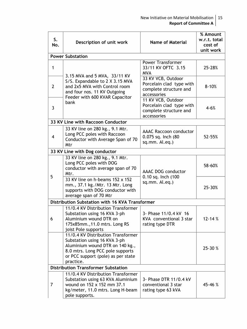
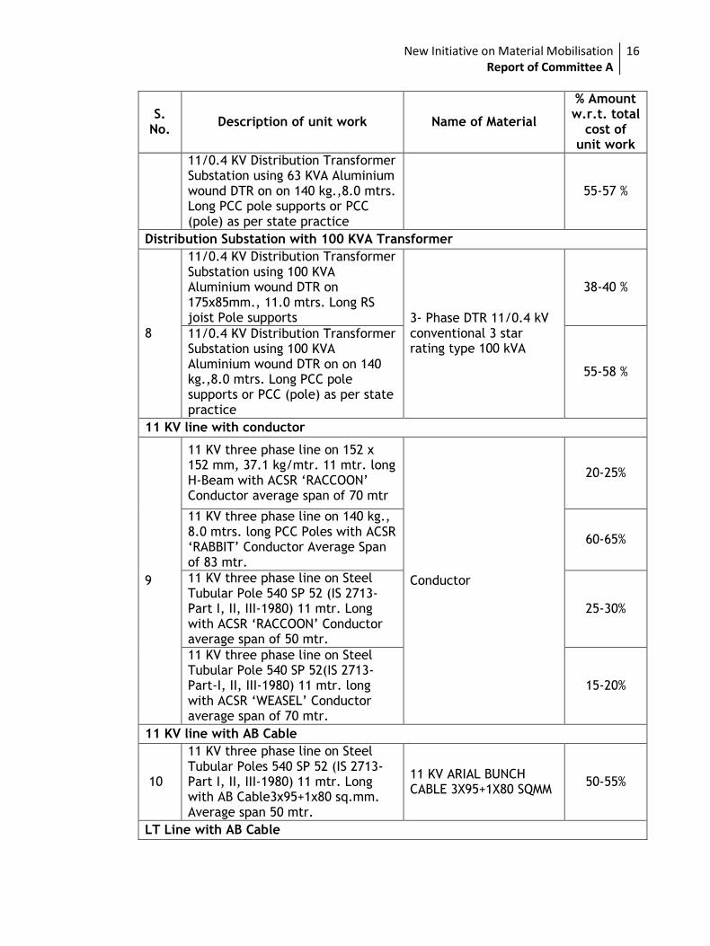
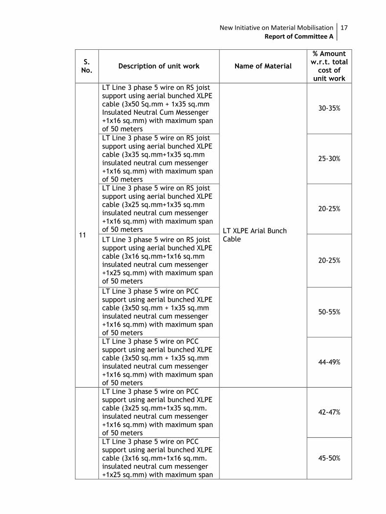
a. The %age share of various materials in per unit quantity of work were
computed. Quantities of major high value materials were considered in
one no of power substation, distribution substation, per kilometre 11 KV
/ 33 KV / LT line. For this purpose, Schedule of Rates (SoR) of per unit
quantities were taken for reference. After examination, the following
were the observations:
New Initiative on Material Mobilisation Report of Committee A
15
S. No.
Description of unit work Name of Material
% Amount w.r.t. total
cost of unit work
Power Substation
1
3.15 MVA and 5 MVA, 33/11 KV S/S. Expandable to 2 X 3.15 MVA and 2x5 MVA with Control room and four nos. 11 KV Outgoing Feeder with 600 KVAR Capacitor bank
Power Transformer 33/11 KV OFTC 3.15 MVA
25-28%
2
33 KV VCB, Outdoor Porcelain clad type with complete structure and accessories
8-10%
3
11 KV VCB, Outdoor Porcelain clad type with complete structure and accessories
4-6%
33 KV Line with Raccoon Conductor
4
33 KV line on 280 kg., 9.1 Mtr. Long PCC poles with Raccoon Conductor with Average Span of 70 Mtr
AAAC Raccoon conductor 0.075 sq. Inch (80 sq.mm. Al.eq.)
52-55%
33 KV Line with Dog conductor
5
33 KV line on 280 kg., 9.1 Mtr. Long PCC poles with DOG conductor with average span of 70 Mtr. AAAC DOG conductor
0.10 sq. Inch (100 sq.mm. Al.eq.)
58-60%
33 KV line on h-beams 152 x 152 mm., 37.1 kg./Mtr. 13 Mtr. Long supports with DOG conductor with average span of 70 Mtr
25-30%
Distribution Substation with 16 KVA Transformer
6
11/0.4 KV Distribution Transformer Substation using 16 KVA 3-ph Aluminium wound DTR on 175x85mm.,11.0 mtrs. Long RS joist Pole supports
3- Phase 11/0.4 kV 16 KVA conventional 3 star rating type DTR
12-14 %
11/0.4 KV Distribution Transformer Substation using 16 KVA 3-ph Aluminium wound DTR on 140 kg., 8.0 mtrs. Long PCC pole supports or PCC support (pole) as per state practice.
25-30 %
Distribution Transformer Substation
7
11/0.4 KV Distribution Transformer Substation using 63 KVA Aluminium wound on 152 x 152 mm 37.1 kg/meter, 11.0 mtrs. Long H-beam pole supports.
3- Phase DTR 11/0.4 kV conventional 3 star rating type 63 kVA
45-46 %
New Initiative on Material Mobilisation Report of Committee A
16
S. No.
Description of unit work Name of Material
% Amount w.r.t. total
cost of unit work
11/0.4 KV Distribution Transformer Substation using 63 KVA Aluminium wound DTR on on 140 kg.,8.0 mtrs. Long PCC pole supports or PCC (pole) as per state practice
55-57 %
Distribution Substation with 100 KVA Transformer
8
11/0.4 KV Distribution Transformer Substation using 100 KVA Aluminium wound DTR on 175x85mm., 11.0 mtrs. Long RS joist Pole supports 3- Phase DTR 11/0.4 kV
conventional 3 star rating type 100 kVA
38-40 %
11/0.4 KV Distribution Transformer Substation using 100 KVA Aluminium wound DTR on on 140 kg.,8.0 mtrs. Long PCC pole supports or PCC (pole) as per state practice
55-58 %
11 KV line with conductor
9
11 KV three phase line on 152 x 152 mm, 37.1 kg/mtr. 11 mtr. long H-Beam with ACSR ‘RACCOON’ Conductor average span of 70 mtr
Conductor
20-25%
11 KV three phase line on 140 kg., 8.0 mtrs. long PCC Poles with ACSR ‘RABBIT’ Conductor Average Span of 83 mtr.
60-65%
11 KV three phase line on Steel Tubular Pole 540 SP 52 (IS 2713-Part I, II, III-1980) 11 mtr. Long with ACSR ‘RACCOON’ Conductor average span of 50 mtr.
25-30%
11 KV three phase line on Steel Tubular Pole 540 SP 52(IS 2713-Part-I, II, III-1980) 11 mtr. long with ACSR ‘WEASEL’ Conductor average span of 70 mtr.
15-20%
11 KV line with AB Cable
10
11 KV three phase line on Steel Tubular Poles 540 SP 52 (IS 2713-Part I, II, III-1980) 11 mtr. Long with AB Cable3x95+1x80 sq.mm. Average span 50 mtr.
11 KV ARIAL BUNCH CABLE 3X95+1X80 SQMM
50-55%
LT Line with AB Cable
New Initiative on Material Mobilisation Report of Committee A
17
S. No.
Description of unit work Name of Material
% Amount w.r.t. total
cost of unit work
11
LT Line 3 phase 5 wire on RS joist support using aerial bunched XLPE cable (3x50 Sq.mm + 1x35 sq.mm Insulated Neutral Cum Messenger +1x16 sq.mm) with maximum span of 50 meters
LT XLPE Arial Bunch Cable
30-35%
LT Line 3 phase 5 wire on RS joist support using aerial bunched XLPE cable (3x35 sq.mm+1x35 sq.mm insulated neutral cum messenger +1x16 sq.mm) with maximum span of 50 meters
25-30%
LT Line 3 phase 5 wire on RS joist support using aerial bunched XLPE cable (3x25 sq.mm+1x35 sq.mm insulated neutral cum messenger +1x16 sq.mm) with maximum span of 50 meters
20-25%
LT Line 3 phase 5 wire on RS joist support using aerial bunched XLPE cable (3x16 sq.mm+1x16 sq.mm insulated neutral cum messenger +1x25 sq.mm) with maximum span of 50 meters
20-25%
LT Line 3 phase 5 wire on PCC support using aerial bunched XLPE cable (3x50 sq.mm + 1x35 sq.mm insulated neutral cum messenger +1x16 sq.mm) with maximum span of 50 meters
50-55%
LT Line 3 phase 5 wire on PCC support using aerial bunched XLPE cable (3x50 sq.mm + 1x35 sq.mm insulated neutral cum messenger +1x16 sq.mm) with maximum span of 50 meters
44-49%
LT Line 3 phase 5 wire on PCC support using aerial bunched XLPE cable (3x25 sq.mm+1x35 sq.mm. insulated neutral cum messenger +1x16 sq.mm) with maximum span of 50 meters
42-47%
LT Line 3 phase 5 wire on PCC support using aerial bunched XLPE cable (3x16 sq.mm+1x16 sq.mm. insulated neutral cum messenger +1x25 sq.mm) with maximum span
45-50%
New Initiative on Material Mobilisation Report of Committee A
18
S. No.
Description of unit work Name of Material
% Amount w.r.t. total
cost of unit work
of 50 meters
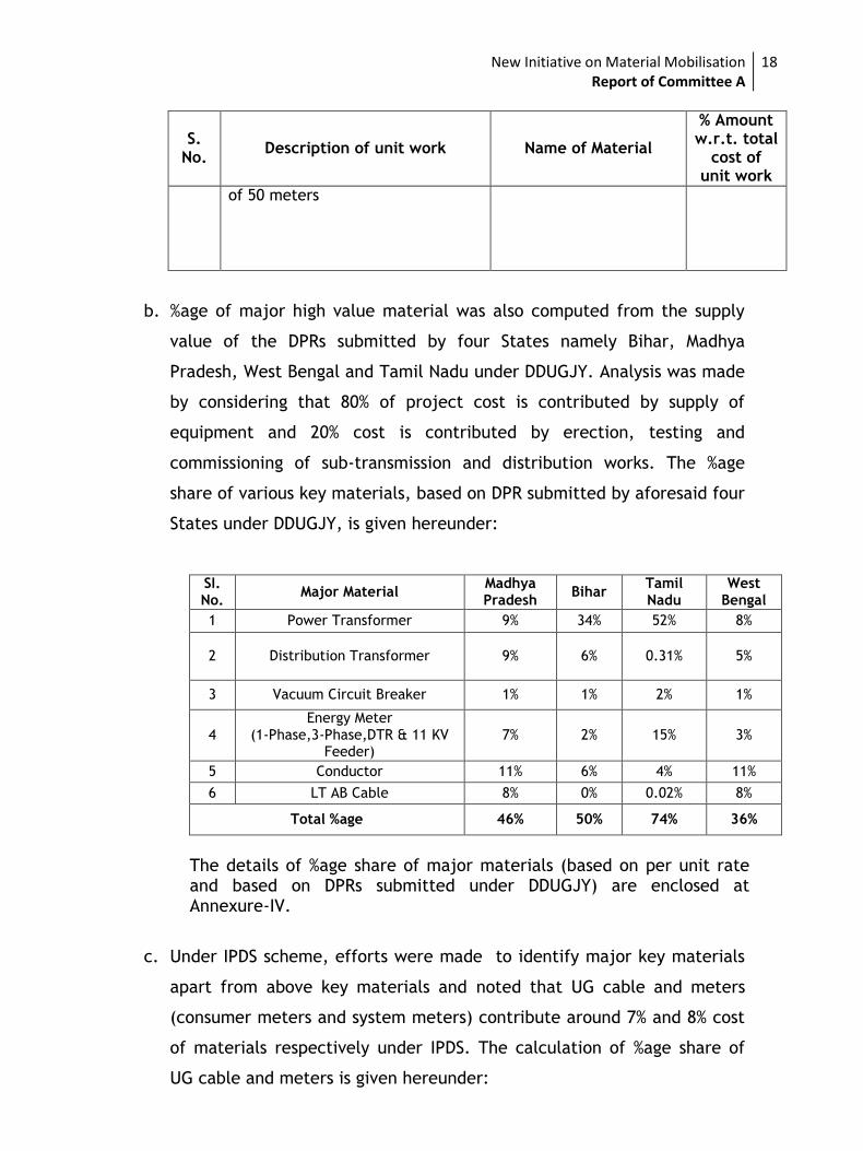
b. %age of major high value material was also computed from the supply
value of the DPRs submitted by four States namely Bihar, Madhya
Pradesh, West Bengal and Tamil Nadu under DDUGJY. Analysis was made
by considering that 80% of project cost is contributed by supply of
equipment and 20% cost is contributed by erection, testing and
commissioning of sub-transmission and distribution works. The %age
share of various key materials, based on DPR submitted by aforesaid four
States under DDUGJY, is given hereunder:
SI. No.
Major Material Madhya Pradesh
Bihar Tamil Nadu
West Bengal
1 Power Transformer 9% 34% 52% 8%
2 Distribution Transformer 9% 6% 0.31% 5%
3 Vacuum Circuit Breaker 1% 1% 2% 1%
4 Energy Meter
(1-Phase,3-Phase,DTR & 11 KV Feeder)
7% 2% 15% 3%
5 Conductor 11% 6% 4% 11%
6 LT AB Cable 8% 0% 0.02% 8%
Total %age 46% 50% 74% 36%
The details of %age share of major materials (based on per unit rate and based on DPRs submitted under DDUGJY) are enclosed at Annexure-IV.
c. Under IPDS scheme, efforts were made to identify major key materials
apart from above key materials and noted that UG cable and meters
(consumer meters and system meters) contribute around 7% and 8% cost
of materials respectively under IPDS. The calculation of %age share of
UG cable and meters is given hereunder:

New Initiative on Material Mobilisation Report of Committee A
19
Name of Item
Qty Total Material Cost
of item Total Sanctioned
Material cost %age share
UG cable 10200 Km Rs 1326 cr
(@ Rs 13 Lakh/ km) Rs 19200 cr
7%
Meters 95 Lakhs Rs 1520 cr 8%
*Assuming material cost contributes 80% of project cost of ~Rs 24,000
cr
The committee then discussed above seven high value major items viz., Power
and Distribution Transformers, All type of Conductors, HT Breakers with control
panel and CTs/PTs, AB/UG Cables of 33 KV, 11 KV and LT and Energy Meters to
be used in DDUGJY/IPDS.
Committee also discussed substantial supply costs of poles and steel structures
in sub-transmission & distribution works. It was intimated that different
Technical Specifications are used for PCC/RCC poles in different states.
Accordingly, pole manufacturers have developed locally to manufacture State
specific poles. Since, State to State different type of supports, different
dimensions of fabricated steel structure items are used, it was decided not to
consider PCC/RCC and steel structure materials under major high value items.
Vacuum Circuit Breaker was also deliberated for inclusion in list of major high
value materials. However, it was noted that two types (indoor & outdoor) of
installation of Vacuum Circuit breakers are used in Sub-transmission &
Distribution system. Considering various voltage levels, type of protection, type
of relays and installation mechanism, there would be various combination
which needs to be incorporated before finalizing quantity for a particular type
of set of breaker for rate contract. Following may be the various type of VCBs
which needs to be captured while deciding quantum of set of Vacuum Circuit
Breakers:
1. Voltage Class i.e. 33 KV or 11 KV
New Initiative on Material Mobilisation Report of Committee A
20
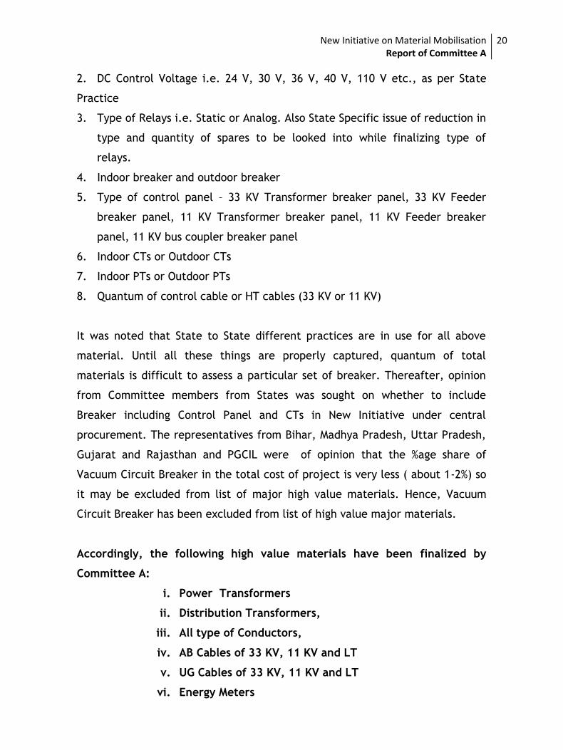
2. DC Control Voltage i.e. 24 V, 30 V, 36 V, 40 V, 110 V etc., as per State
Practice
3. Type of Relays i.e. Static or Analog. Also State Specific issue of reduction in
type and quantity of spares to be looked into while finalizing type of
relays.
4. Indoor breaker and outdoor breaker
5. Type of control panel – 33 KV Transformer breaker panel, 33 KV Feeder
breaker panel, 11 KV Transformer breaker panel, 11 KV Feeder breaker
panel, 11 KV bus coupler breaker panel
6. Indoor CTs or Outdoor CTs
7. Indoor PTs or Outdoor PTs
8. Quantum of control cable or HT cables (33 KV or 11 KV)
It was noted that State to State different practices are in use for all above
material. Until all these things are properly captured, quantum of total
materials is difficult to assess a particular set of breaker. Thereafter, opinion
from Committee members from States was sought on whether to include
Breaker including Control Panel and CTs in New Initiative under central
procurement. The representatives from Bihar, Madhya Pradesh, Uttar Pradesh,
Gujarat and Rajasthan and PGCIL were of opinion that the %age share of
Vacuum Circuit Breaker in the total cost of project is very less ( about 1-2%) so
it may be excluded from list of major high value materials. Hence, Vacuum
Circuit Breaker has been excluded from list of high value major materials.
Accordingly, the following high value materials have been finalized by
Committee A:
i. Power Transformers
ii. Distribution Transformers,
iii. All type of Conductors,
iv. AB Cables of 33 KV, 11 KV and LT
v. UG Cables of 33 KV, 11 KV and LT
vi. Energy Meters
New Initiative on Material Mobilisation Report of Committee A
21
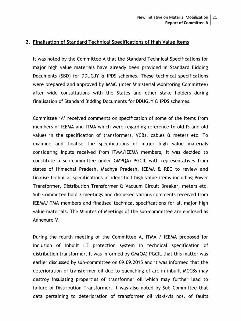
2. Finalisation of Standard Technical Specifications of High Value Items
It was noted by the Committee A that the Standard Technical Specifications for
major high value materials have already been provided in Standard Bidding
Documents (SBD) for DDUGJY & IPDS schemes. These technical specifications
were prepared and approved by IMMC (Inter Ministerial Monitoring Committee)
after wide consultations with the States and other stake holders during
finalisation of Standard Bidding Documents for DDUGJY & IPDS schemes.
Committee ‘A’ received comments on specification of some of the items from
members of IEEMA and ITMA which were regarding reference to old IS and old
values in the specification of transformers, VCBs, cables & meters etc. To
examine and finalise the specifications of major high value materials
considering inputs received from ITMA/IEEMA members, it was decided to
constitute a sub-committee under GM9QA) PGCIL with representatives from
states of Himachal Pradesh, Madhya Pradesh, IEEMA & REC to review and
finalise technical specifications of identified high value items including Power
Transformer, Distribution Transformer & Vacuum Circuit Breaker, meters etc.
Sub Committee hold 3 meetings and discussed various comments received from
IEEMA/ITMA members and finalised technical specifications for all major high
value materials. The Minutes of Meetings of the sub-committee are enclosed as
Annexure-V.
During the fourth meeting of the Committee A, ITMA / IEEMA proposed for
inclusion of inbuilt LT protection system in technical specification of
distribution transformer. It was informed by GM(QA) PGCIL that this matter was
earlier discussed by sub-committee on 09.09.2015 and it was informed that the
deterioration of transformer oil due to quenching of arc in inbuilt MCCBs may
destroy insulating properties of transformer oil which may further lead to
failure of Distribution Transformer. It was also noted by Sub Committee that
data pertaining to deterioration of transformer oil vis-à-vis nos. of faults
New Initiative on Material Mobilisation Report of Committee A
22
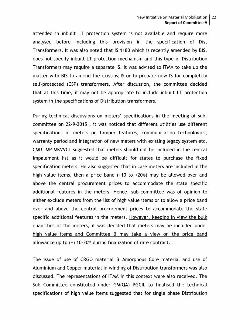
attended in inbuilt LT protection system is not available and require more
analysed before including this provision in the specification of Dist
Transformers. It was also noted that IS 1180 which is recently amended by BIS,
does not specify inbuilt LT protection mechanism and this type of Distribution
Transformers may require a separate IS. It was advised to ITMA to take up the
matter with BIS to amend the existing IS or to prepare new IS for completely
self-protected (CSP) transformers. After discussion, the committee decided
that at this time, it may not be appropriate to include inbuilt LT protection
system in the specifications of Distribution transformers.
During technical discussions on meters’ specifications in the meeting of sub-
committee on 22-9-2015 , it was noticed that different utilities use different
specifications of meters on tamper features, communication technologies,
warranty period and integration of new meters with existing legacy system etc.
CMD, MP MKVVCL suggested that meters should not be included in the central
impalement list as it would be difficult for states to purchase the fixed
specification meters. He also suggested that in case meters are included in the
high value items, then a price band (+10 to +20%) may be allowed over and
above the central procurement prices to accommodate the state specific
additional features in the meters. Hence, sub-committee was of opinion to
either exclude meters from the list of high value items or to allow a price band
over and above the central procurement prices to accommodate the state
specific additional features in the meters. However, keeping in view the bulk
quantities of the meters, it was decided that meters may be included under
high value items and Committee B may take a view on the price band
allowance up to (+) 10-20% during finalization of rate contract.
The issue of use of CRGO material & Amorphous Core material and use of
Aluminium and Copper material in winding of Distribution transformers was also
discussed. The representations of ITMA in this context were also received. The
Sub Committee constituted under GM(QA) PGCIL to finalised the technical
specifications of high value items suggested that for single phase Distribution
New Initiative on Material Mobilisation Report of Committee A
23
transformers of 25 KVA and below, CRGO/ Amorphous Core material and
Aluminium as winding material may be used while all 3 Phase Distribution
Transformers would use only CRGO core material with aluminium winding in
less than 200 KVA Transformers and copper winding in above 200 KVA
transformers. The committee deliberated on the issue in detail and the view
of States were also taken on the matter. Many of the states informed that they
use only CRGO material Distribution transformers due to lack of repairing
facilities in case of failure of Amorphous Core transformers. It was also noted
that Indian standards of Amorphous Core material is still not available and is
under preparation. Few States also indicated that copper wound transformers
are costly than aluminium wound transformers and also theft prone. However,
it was decided that it would not be appropriate to restrict the specification for
one type of core material & winding material for distribution transformers as
States use both type of transformers as per their requirement. After examining
the matter, it was decided that the specification of Distribution transformers,
as finalised by sub-committee, would be modified to include both the core
material ( CRGO/ Amorphous) and both winding material( Al/Cu) for
distribution transformers and states may choose the appropriate transformer
as per their requirement.
Copy of finalised technical specifications is attached at Annexure-VI.
3. Aggregation of quantity of major high value materials
The matter related to aggregation of quantity of major high value materials
under DDUGJY & IPDS schemes was discussed in detail by committee members
during all the four meetings. It was noted that DPRs worth Rs 85,347 crores
were submitted by states under DDUGJY on web portal, while based on the
technical appraisal and availability of funds, Monitoring Committee approved
DPRs worth Rs 40,204 crores only. Since the sanctioned amount of DPRs of
various States was less than the amount of DPRs submitted on the online
portal, the States were advised to submit supplementary DPRs based on the
New Initiative on Material Mobilisation Report of Committee A
24
approved cost. It was noted that extracting quantities of major high value
materials from online portal for States wherein sanctioned amount is less than
submitted DPR cost, would be a challenge and the concurrence of states is also
needed in finalizing the quantities.
Keeping in view the time constraints, it was decided to organize a workshop
with nodal officers of states to finalize the quantities under DDUGJY/IPDS.
Accordingly, a workshop was organized on 12th& 13th Sep 2015 at New Delhi and
was attended by 55 representatives of 32 utilities of the states. The list of
participants in the workshop is enclosed at Annexure-VII. During the workshop,
the representative of states submitted the revised quantities of major high
value materials under DDUGJY & IPDS schemes. Efforts were also taken to
consolidate the quantity of major materials under all sub-transmission &
distribution schemes in States other than DDUGJY/IPDS but State
representatives informed that other schemes funded by other funding agencies
like JICA, World Bank etc have their own agreed methodology for procurement,
hence, the States expressed their unwillingness to include those requirement
under this initiative of centralized finalization of rate contract.
While computing aggregate quantity of materials, following methodology were
used:
a. Materials required for electrification of UE villages were not included in
aggregate quantity as States have been permitted to execute these
works departmentally on priority using their own resources.
b. The States where sanctioned amount of DPRs is less than the amount of
submitted DPRs and wherein States have not provided the quantities of
major materials, tentative quantity has been considered while
computing aggregate quantity of materials.
New Initiative on Material Mobilisation Report of Committee A
25
c. For States where permission has been granted by Monitoring Committee
to
execute works on partial turnkey or departmental execution mode under
DDUGJY Scheme have not been considered while computing quantity of
materials. However, quantities for all sanctioned DPRs under IPDS have
been considered, whether executed on turnkey, semi-turnkey or
departmental basis, since key materials are to be procured in all cases.
d. The quantity of major high value materials by States, wherein Monitoring
Committee sanctioned almost 100% proposed DPRs works, has been
extracted from online portal based on DPRs submitted by them.
e. Some of the states like Gujarat & Tamil Nadu have not furnished the
quantities of items stating that they had already published the tenders
for DDUGJY/ IPDS projects as per the sanctioned cost and they have no
requirement under central procurement.
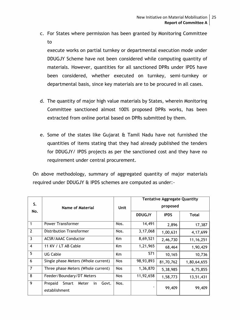
On above methodology, summary of aggregated quantity of major materials
required under DDUGJY & IPDS schemes are computed as under:-
S.
No. Name of Material Unit
Tentative Aggregate Quantity
proposed
DDUGJY IPDS Total
1 Power Transformer Nos. 14,491 2,896 17,387
2 Distribution Transformer Nos. 3,17,068 1,00,631 4,17,699
3 ACSR/AAAC Conductor Km 8,69,521 2,46,730 11,16,251
4 11 KV / LT AB Cable Km 1,21,965 68,464 1,90,429
5 UG Cable Km 571 10,165 10,736
6 Single phase Meters (Whole current) Nos 98,93,893 81,70,762 1,80,64,655
7 Three phase Meters (Whole current) Nos 1,36,870 5,38,985 6,75,855
8 Feeder/Boundary/DT Meters Nos 11,92,658 1,58,773 13,51,431
9 Prepaid Smart Meter in Govt.
establishment
Nos. - 99,409 99,409
New Initiative on Material Mobilisation Report of Committee A
26
As the above quantities are based on the tentative data furnished by States,
the above quantities may vary during the actual implementation of the
projects. The State-wise and rating-wise details of major materials for DDUGJY
& IPDS are enclosed at Annexure-VII.
4. Aggregation of quantity of Smart Meters
During a meeting with Secretary (Power) and Additional Secretary (Power) on
1st Oct 2015, it was directed that Committee A may also assess the approximate
quantities of Smart Meters under various categories of consumers. As per the
data/information available in CEA in 2014, there were about 21.83 Crores of
various categories of consumers in the country. Out of total of 21.83 Crores
consumer base, 17.12 Crores (78.4%) were domestic consumers (8.18 Crores
(37.5%) urban domestic and 8.9 Crores (40.9%) rural domestic), 1.90 Crore
(8.7%) were agriculture consumers, 1.97 Crores (9%) were commercial
consumers, 0.35 Crores (1.6%) were Industrial low and medium voltage
consumers and 0.17 Crores (0.7%) belonged to public category viz. Public
Lighting, Public Water Works and Sewage Pumping. ‘Other category’ of
consumers (viz bulk miscellaneous, army and paramilitary establishment etc)
were about 30 lakh (1.4%) including Traction consumers of 412 only.
During the meetings of the Committee A, PFC representative indicated that
they had collected the data from states to work out the tentative quantities of
smart meters under two categories (more than 500 Units/ month and 200-500
Units/ month). In case of some of the states, which did not furnish data, the
requirement has been assessed based on the total consumers in the state.
Based on the data received by PFC, it is estimated that the requirement of
smart meters would be around 1 Crores, in case the smart meters are installed
for those consumer which are consuming more than 500 units / month.
Additionally, 2.5 Crore more smart meters would also be required in case these
meters are installed on the consumers consuming 200-500 units/ month. So, a
New Initiative on Material Mobilisation Report of Committee A
27
total of about 3.5 Crore Smart Meters would be required in case, these meters
are installed for those consumers which are consuming more than 200 units/
month
It was observed by the Committee that Indian Standards (IS) of single phase
whole current smart meters have recently been published by BIS but the
commercial production of these meters as per IS and as per specific
requirement of states may take some time. The state wise proposed quantities
of Smart meters based on categories of 200-500 units/ month and more than
500 units / month are consolidated and are enclosed at Annexure-IX.
The Committee ‘A’ extend their sincere appreciation to the efforts made by
CEA, REC, PFC, PGCIL and States in finalizing the report of the Committee.
Recommendations:
1. The list of major high value materials finalised by Committee A are given
hereunder:
i. Power Transformers
ii. Distribution Transformers,
iii. All type of Conductors,
iv. AB Cables of 33 KV, 11 KV and LT
v. UG Cables of 33 KV, 11 KV and LT
vi. Energy Meters
2. The Technical Specification of major high value materials are enclosed
with the report.
3. The aggregate quantity of major high value materials is given hereunder:
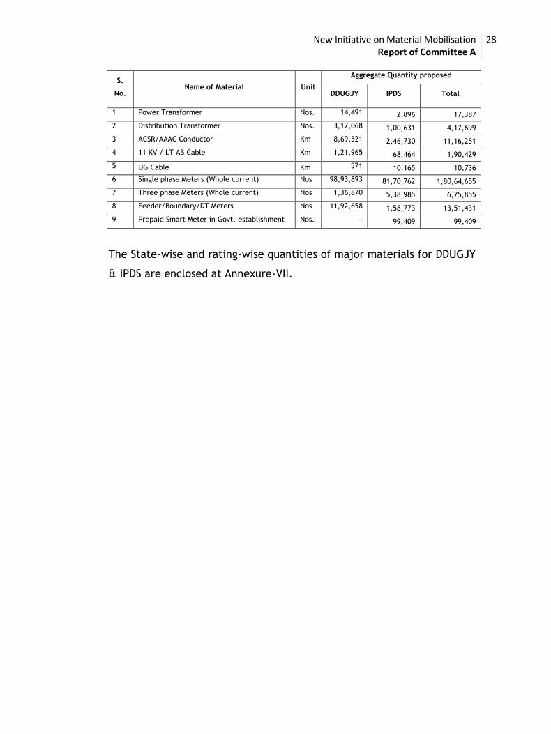
New Initiative on Material Mobilisation Report of Committee A
28
S.
No. Name of Material Unit
Aggregate Quantity proposed
DDUGJY IPDS Total
1 Power Transformer Nos. 14,491 2,896 17,387
2 Distribution Transformer Nos. 3,17,068 1,00,631 4,17,699
3 ACSR/AAAC Conductor Km 8,69,521 2,46,730 11,16,251
4 11 KV / LT AB Cable Km 1,21,965 68,464 1,90,429
5 UG Cable Km 571 10,165 10,736
6 Single phase Meters (Whole current) Nos 98,93,893 81,70,762 1,80,64,655
7 Three phase Meters (Whole current) Nos 1,36,870 5,38,985 6,75,855
8 Feeder/Boundary/DT Meters Nos 11,92,658 1,58,773 13,51,431
9 Prepaid Smart Meter in Govt. establishment Nos. - 99,409 99,409
The State-wise and rating-wise quantities of major materials for DDUGJY
& IPDS are enclosed at Annexure-VII.
New Initiative on Material Mobilisation Report of Committee A
29
Annexure-I
MoP’s OM
on
Committees Formation
for
New Initiative on
Material Mobilisation
New Initiative on Material Mobilisation Report of Committee A
30
New Initiative on Material Mobilisation Report of Committee A
31
New Initiative on Material Mobilisation Report of Committee A
32
New Initiative on Material Mobilisation Report of Committee A
33
New Initiative on Material Mobilisation Report of Committee A
34
New Initiative on Material Mobilisation Report of Committee A
35
New Initiative on Material Mobilisation Report of Committee A
36
Annexure-II:
Minutes of Meetings
Of
Committee-A
New Initiative on Material Mobilisation Report of Committee A
37
First meeting of Committee ‘A’ held on 22.08.2015 in REC Board Room, New Delhi on
MoP Initiative to facilitate States in mobilization of quality equipment/materials
at competitive price under DDUGJY and IPDS
The first meeting of the Committee constituted by MOP to facilitate States in mobilization of quality equipment/materials at competitive price under DDUGJY and IPDS was held on 22.08.2015 in New Delhi. The list of participants is at Annex-I. Chairman of the Committee ‘A’ welcomed the participants. Member Secretary of the
Committee intimated details on formation of committee, Terms of Reference (ToR)
and the dead line assigned to complete the assignment thereof.
Term of Reference of the Committee Á‘
a. To prepare and finalize list of major high value materials under sub-
transmission & distribution system to be procured from empanelled agencies.
b. To prepare the standard technical specifications/ tender drawings / tender
data sheet of selected major materials.
c. Aggregating project wise/DISCOM wise requirement of selected major
materials matching with mobilization of working agencies, completion of
survey activities, seasonal acceptance, and prioritization of works and
availability of fronts.
d. To finalize volume of materials to be tendered in a lot in line with aggregate
project wise/DISCOM wise requirements.
e. Centralized vendor empanelment based on manufacturers’ manufacturing
capacity at works, technical experience, financial capability, existing type test
certification, testing facilities requirements, past performance of supplied
equipment, litigation history.
Thereafter, Chairperson CEA invited the participants on the approach, action plan and
suggestions to complete the assigned tasks by time line of three weeks. The outline of
the points discussed and views of participants are as under:
1) Preparing list of high value major items under IPDS & DDUGJY:
a) The representative of REC intimated that based on schedule of rates of one of
the states, percentage cost share of various materials in unit length of lines or
substation is computed (copy enclosed). It depicts the high value major
materials in sub-transmission and distribution works. A list of such materials
was presented during the discussion. It includes following items:
New Initiative on Material Mobilisation Report of Committee A
38
(1) Power as well as Distribution Transformers,
(2) Overhead conductors (AAC/ACSR/AAAC)
(3) HT & LT Breakers
(4) Steel Poles (Rail, H-Beam, RS Joist, Steel Tubular Poles)
(5) Energy Meters
(6) LT Distribution Board
(7) HT and LT Power Cables including ABC Cables
(8) Distribution Box for service connection
(9) Capacitor Banks
(10) Lightening Arresters
(11) LED Bulbs
(12) Steel structure materials
b) Based on above, comments from all the participating members were sought to
finalise list of high value major materials to be considered under Rate Contract
mechanism under IPDS and DDUGJY schemes. Following were the comments of
members:
i) The representative of Bihar state intimated that before onset of
centrally funded sub-transmission and distribution reform scheme namely
APDRP, similar practice of partial turnkey execution was followed by
almost all the states to execute sub-transmission and distribution works
at site. This concept was changed to total turnkey execution mode.
Demerits of Turnkey Execution are now available in all the states. The
advantage under turnkey execution mode are day to day Project
Management by the contractor, planning and mobilization of all
materials under single point responsibilities to contractor. Whereas a key
demerit of turnkey execution that item-wise rate are different in
different projects in same discom area. He welcome the initiative taken
by GoI to address this important demerit.
ii) The representative of Gujarat State stated that all types of Transformer,
Conductors, Steel Poles (RS Joist, Steel Tubular and Rail), HT Cables,
Capacitor Bank, HT & LT Breakers, Lightening Arrestors, and Energy
Meters are to be included in the list of materials to be centrally
procured. Rest of the material may allowed under the scope of partial
turnkey contractors.
iii) The representative of Madhya Pradesh State stated that LT breaker, GI
wire Distribution Box and Cable Box not to be considered through rate
contract as there are various vendors available in the states and these
items are not high value materials. He requested to include “feeder
metering equipment” under central procurement plan.
iv) The representative of Rajasthan State opined to exclude Conductor and
Energy Meter procurement through rate contract mechanism.
New Initiative on Material Mobilisation Report of Committee A
39
v) The representative of Himachal Pradesh opined to include all the
suggested materials for the procurement as depicted in the list through
rate contract.
vi) The representative of Utter Pradesh State intimated that all the
materials in suggestive list except LT Cables may be procured through
rate contract.
vii) The representative of Telangana State suggested to remove small value
items like LT Distribution Box, GI Wires, Cable Boxes and LT Cables from
the suggestive list of procurement through rate contract.
viii) The representative of PGCIL suggested to include only four key materials
namely Power/Distribution Transformers, Overhead Conductors, HT
Cables and Energy Meters in the list for procurement through rate
contract. To ensure quality of balance sub-transmission and distribution
materials, he also suggested to empanel all the prospective vendors but
invite quote for above four items only for rate contract.
ix) The representative of PFC suggested to include meters with modem
under procurement. He also suggested to include feeder metering
equipment under the list.
Concluding the discussions, the committee unanimously decided to include
following major materials for central procurement plan:
(1) Power and Distribution Transformers,
(2) All type of Conductors,
(3) HT Breakers with control panel and CTs/PTs,
(4) Steel Poles (RS Joist, H-Beam and Steel Tubular Poles)
(5) HT cables,
(6) AB Cables of 33 KV, 11 KV and LT
(7) Capacitor Banks,
(8) Energy Meters,
(9) Feeder Metering Equipment
2) Finalization of Tech Specifications/drawings and Data sheet:
The representative of REC had intimated that technical specifications of all the
major higher value items are available in Standard Bidding Documents of
IPDS/DDUGJY schemes. Copy of the same is available on IPDS and DDUGJY web
portals. He further added that any change in these specification based on state
practices may be suggested to finalize the specification to start process for
finalization of rate contract.
Keeping dead line for completion period of assignment by the committee in view,
it was decided by the committee members that members shall suggest any
New Initiative on Material Mobilisation Report of Committee A
40
improvement in these specifications by Wednesday i.e. 26.08.2015. In case, no
suggestion (s) is received, the existing technical specifications shall be considered
fit to initiate action for rate contract finalization.
3) Aggregating major high value materials requirements:
Issue related to zone wise quantities to be considered for rate contract was
discussed in detailed. It was unanimously decided to ask States to submit
quantities of above high value materials to be considered for procurement
centrally by Wednesday i.e. by 26.08.2015.
It was also decided to compute project wise requirements of high value major
materials through on-line DPRs submitted by the states under DDUGJY & IPDS. For
balance projects which are yet to be sanctioned; it was intimated by REC and PFC
that more than 70% IPDS and DDUGJY projects have already been sanctioned by
IMMC. The list of materials against those states where DPRs are yet to be framed,
are to be extrapolated to arrive at zone wise quantities of materials.
4) Empanelment of Centralized Vendor for Procuring Key Materials
Representative from REC intimated that empanelment of vendors is time taking
exercise. It would involve finalization of zone-wise & item-wise pre-qualification
requirements, press advertisement, detailed technical & commercial examination
of offers received from prospective bidders.
Accordingly, committee discussed various sub-activities involved in empanelment
of vendors, their inter-dependencies and their expected completion period in
detail. Committee also discussed the ToR of committee B in relation to calling of
bids to finalise the rate of contracts. Suggestion were sought from the
participating members of the committee to perform empanelment of vendors in
three week time period. On this matter, following was opined:
i) The representative of Bihar State was of the view that nature of work is
complex and voluminous in nature. Hence, it is not possible to complete
the assignment within given time frame of three weeks. He added that
finalization of pre-qualification requirement and rate contract are inter-
linking activities and therefore these two activities must be assigned to a
single committee.
ii) Director General IEEMA and Dy. Director General ITMA opined to assign
responsibilities empanelment of vendors to committee-B. However, they
raised their concerned over re-constitution of committee-B as IEEMA/ITMA
representation is not included in it.
iii) The representative of Gujrat had intimated that activities of empanelment
and finalization of rate contract is time taking and therefore be assigned to
a single committee. He also apprehended that no single vendor in our
New Initiative on Material Mobilisation Report of Committee A
41
country can manufacture and supply even 50% quantity of single item if we
add demands of such material in a zone.
iv) The representative of MP felt that assigned task given by MoP is to be
honored. However, he opined that assignment of empanelment and
finalization of rate contract is too-time consuming works. He added that it
cannot be completed within the given time frame. He suggested to
consider existing approved sub-vendors/manufacturers for finalization of
rate contract. All the list of approved vendors may be collected and
compiled zone-wise for empanelment and finalization of rate contract.
Member Secretary stated that the approved vendors are capable to meet
the need of state or discom only. However, while empanelling
manufactures for zone wise materials, they may not be capable.
v) The representative of Uttar Pradesh State suggested that empanelment and
finalization of rate contract may be taken up by Committee-B as both the
activities are inter related.
vi) The representative of Rajasthan State also opined that empanelment and
finalization of rate contract is time taking and same cannot be completed
in the given time frame.
vii) Himachal Pradesh state representative stated that empanelment and
finalization of rate contract be given to committee-B as both the activities
are co-related.
viii) Telangana state representative suggested that empanelment and
finalization of rate contract may be done by committee-B.
ix) The representative of PFC had informed that Standard Bidding Documents
(SBD) are available and QR of SBD may be adopted for finalization of vendor
as preparation of QR and finalization of vendor shall be time consuming. He
further stated that technical capability may be kept in consideration while
preparing PQR.
Member Secretary clarified that SBD for DDUGJY/IPDS are related to
execution of works and same cannot be used for vendor finalization.
Therefore, separate PQR would be needed for vendor empanelment.
Member/PFC also suggested for formation of sub-committees for zone wise
evaluation of vendors without considering financial evaluation of vendor.
He also suggested to seek States feedback before empanelment and
finalization of rate contract.
Chairperson CEA, while concluding the discussions, mentioned that state approved
vendors cannot be considered as empanelled vendors under present case.
However, he agreed to consider them while finalizing empanelment of vendors. He
opined that stipulated time of 3 weeks is too short to perform this activity because
New Initiative on Material Mobilisation Report of Committee A
42
various statutory procedures are to be followed while finalizing list of empanelled
vendors for a material. Also, a dedicated cell for this purpose would also be
required to be set up for this activity.
On further discussing the matter, Members of the committee were unanimously of
the view that empanelment of vendors for various high value materials is a huge
task and will not be possible within stipulated time frame of 3 weeks as per the
laid procedure for tendering. It would also require a dedicated cell for this
tendering & evaluation purposes. Hence, it was unanimously decided that it would
be appropriate that this assignment of empanelment may be assigned to
committee B or more time (about 6 months)with separate and dedicated cell may
be approved to carry out the task by committee A.
5) Next meeting:
Head of committee decided that 2nd meeting of Committee members shall be held
on 28.08.2015 at 5 PM in REC office.
Meeting ended with vote of thanks to the Chair.
New Initiative on Material Mobilisation Report of Committee A
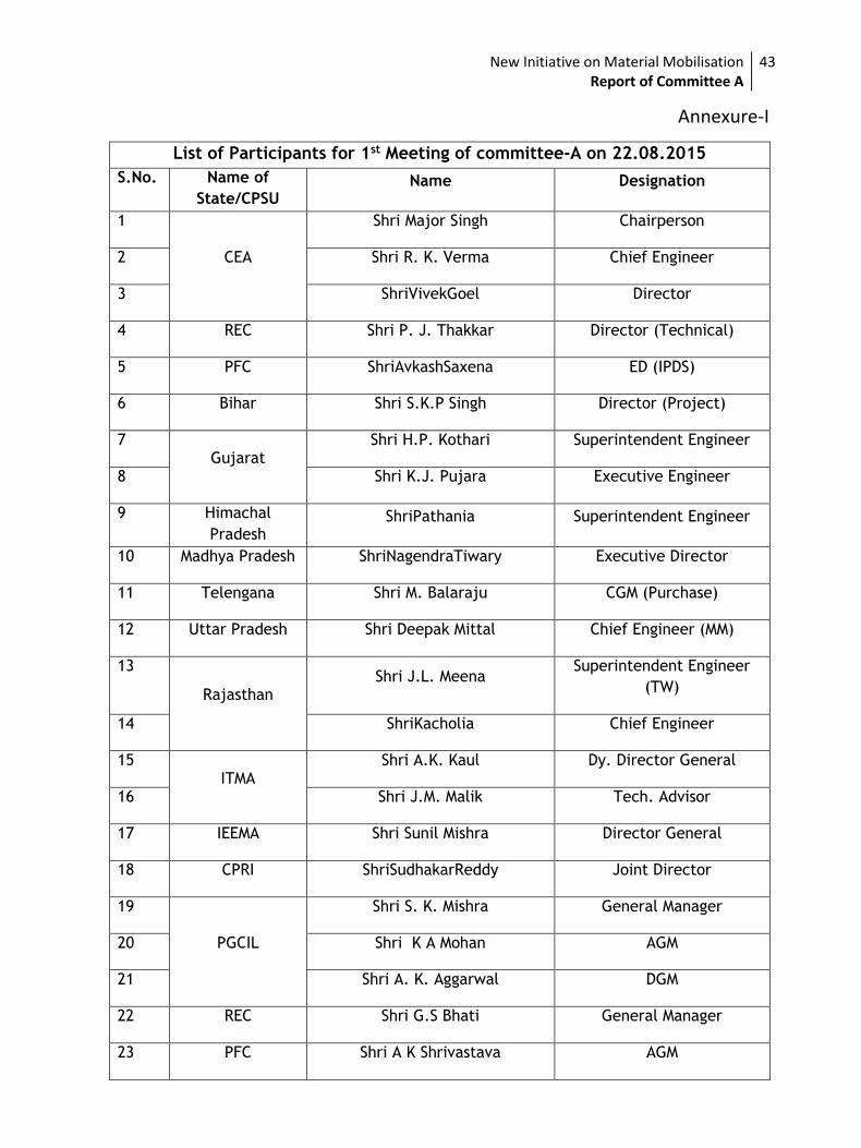
43
List of Participants for 1st Meeting of committee-A on 22.08.2015
S.No. Name of
State/CPSU Name Designation
1
CEA
Shri Major Singh Chairperson
2 Shri R. K. Verma Chief Engineer
3 ShriVivekGoel Director
4 REC Shri P. J. Thakkar Director (Technical)
5 PFC ShriAvkashSaxena ED (IPDS)
6 Bihar Shri S.K.P Singh Director (Project)
7 Gujarat
Shri H.P. Kothari Superintendent Engineer
8 Shri K.J. Pujara Executive Engineer
9 Himachal
Pradesh ShriPathania Superintendent Engineer
10 Madhya Pradesh ShriNagendraTiwary Executive Director
11 Telengana Shri M. Balaraju CGM (Purchase)
12 Uttar Pradesh Shri Deepak Mittal Chief Engineer (MM)
13
Rajasthan Shri J.L. Meena
Superintendent Engineer
(TW)
14 ShriKacholia Chief Engineer
15 ITMA
Shri A.K. Kaul Dy. Director General
16 Shri J.M. Malik Tech. Advisor
17 IEEMA Shri Sunil Mishra Director General
18 CPRI ShriSudhakarReddy Joint Director
19
PGCIL
Shri S. K. Mishra General Manager
20 Shri K A Mohan AGM
21 Shri A. K. Aggarwal DGM
22 REC Shri G.S Bhati General Manager
23 PFC Shri A K Shrivastava AGM
Annexure-I
New Initiative on Material Mobilisation Report of Committee A
44
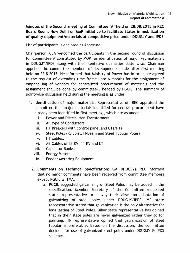
Minutes of the Second meeting of Committee ‘A’ held on 28.08.2015 in REC
Board Room, New Delhi on MoP Initiative to facilitate States in mobilization
of quality equipment/materials at competitive price under DDUGJY and IPDS
List of participants is enclosed as Annexure.
Chairperson, CEA welcomed the participants in the second round of discussion
for Committee A constituted by MOP for identification of major key materials
in DDUGJY/IPDS along with their tentative quantities state wise. Chairman
apprised the committee members of developments made after first meeting
held on 22-8-2015. He informed that Ministry of Power has in-principle agreed
to the request of extending time frame upto 6 months for the assignment of
empanelling of vendors for centralized procurement of materials and the
assignment shall be done by committee-B headed by PGCIL. The summary of
point-wise discussion held during the meeting is as under:
1. Identification of major materials: Representative of REC appraised the
committee that major materials identified for central procurement have
already been identified in first meeting , which are as under -
i. Power and Distribution Transformers,
ii. All type of Conductors,
iii. HT Breakers with control panel and CTs/PTs,
iv. Steel Poles (RS Joist, H-Beam and Steel Tubular Poles)
v. HT cables,
vi. AB Cables of 33 KV, 11 KV and LT
vii. Capacitor Banks,
viii. Energy Meters,
ix. Feeder Metering Equipment
2. Comments on Technical Specification: GM (DDUGJY), REC informed
that no major comments have been received from committee members
except PGCIL & ITMA.
a. PGCIL suggested galvanizing of Steel Poles may be added in the
specification. Member Secretary of the Committee requested
states representative to convey their views on adaptation of
galvanizing of steel poles under DDUGJY/IPDS. MP state
representative stated that galvanization is the only alternative for
long lasting of Steel Poles. Bihar state representative has opined
that in their state poles are never galvanized rather they go for
painting. HP representative opined that galvanization of steel
tubular is preferable. Based on the discussion, the committee
decided for use of galvanized steel poles under DDUGJY & IPDS
schemes.
New Initiative on Material Mobilisation Report of Committee A
45
b. ITMA suggested minor correction in the existing technical
specification of transformers in percentage impedance and to
align in line with IS-1180(Part-I): 2014. Committee agreed to
make the corrections in the existing technical specification.
Member Secretary of the Committee emphasized that all
distribution transformer specification shall conform to IS
1180(Part-1): 2014 and shall comply to quality control order on
transformers including amendments issued thereof by Ministry of
Heavy Industries & Public Enterprise.
The committee sought comments of IEEMA on existing technical
specifications under DDUGJY& IPDS schemes. It was decided that
IEEMA will furnish comments of their members by 02.09.2015.
3. Estimation of Major Materials Requirement including Smart meters:
Representative of PFC informs the Committee that they had compiled
the data regarding tentative quantities of major items based on DPR
submitted by state utilities under IPDS scheme. These tentative
quantities would be sent to states for validation and states would be
requested to confirm the same by Tuesday i.e. 02.09.2015. They have
also collected the tentative quantities of smart meters which would also
be finalized after confirmation from states.
The representative of REC intimated that quantities of major high value
materials shall be compiled from online DPRs and shall be sent to
respective states for validation by 02.09.2015. The states shall be
requested to validate quantities of materials by 04.09.2015, so that zone
wise compilation of quantities may be finalized before the next meeting
of committee.
It was agreed that next meeting of committee shall held on 07.09.2015
at 11.00AM at REC.
Meeting ended with vote of thanks to chair.
New Initiative on Material Mobilisation Report of Committee A
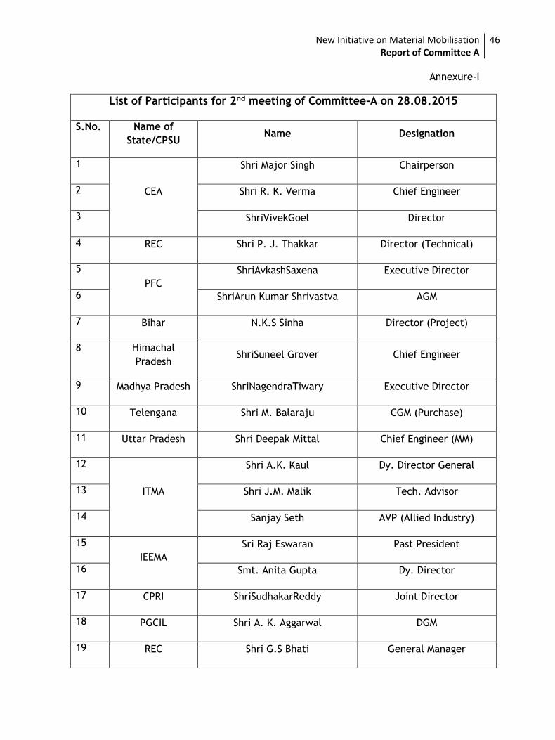
46
Annexure-I
List of Participants for 2nd meeting of Committee-A on 28.08.2015
S.No. Name of
State/CPSU Name Designation
1
CEA
Shri Major Singh Chairperson
2 Shri R. K. Verma Chief Engineer
3 ShriVivekGoel Director
4 REC Shri P. J. Thakkar Director (Technical)
5
PFC
ShriAvkashSaxena Executive Director
6 ShriArun Kumar Shrivastva AGM
7 Bihar N.K.S Sinha Director (Project)
8 Himachal
Pradesh ShriSuneel Grover Chief Engineer
9 Madhya Pradesh ShriNagendraTiwary Executive Director
10 Telengana Shri M. Balaraju CGM (Purchase)
11 Uttar Pradesh Shri Deepak Mittal Chief Engineer (MM)
12
ITMA
Shri A.K. Kaul Dy. Director General
13 Shri J.M. Malik Tech. Advisor
14 Sanjay Seth AVP (Allied Industry)
15
IEEMA
Sri Raj Eswaran Past President
16 Smt. Anita Gupta Dy. Director
17 CPRI ShriSudhakarReddy Joint Director
18 PGCIL Shri A. K. Aggarwal DGM
19 REC Shri G.S Bhati General Manager
New Initiative on Material Mobilisation Report of Committee A
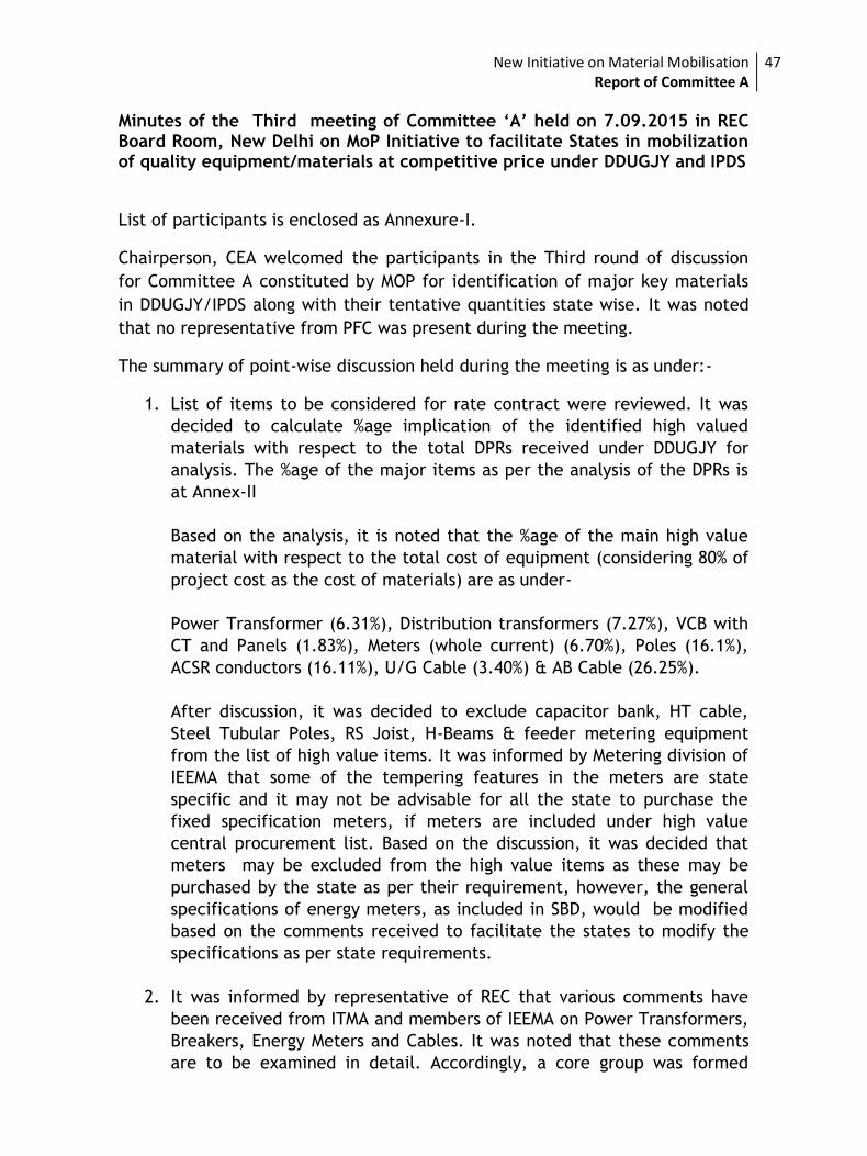
47
Minutes of the Third meeting of Committee ‘A’ held on 7.09.2015 in REC Board Room, New Delhi on MoP Initiative to facilitate States in mobilization of quality equipment/materials at competitive price under DDUGJY and IPDS
List of participants is enclosed as Annexure-I.
Chairperson, CEA welcomed the participants in the Third round of discussion
for Committee A constituted by MOP for identification of major key materials
in DDUGJY/IPDS along with their tentative quantities state wise. It was noted
that no representative from PFC was present during the meeting.
The summary of point-wise discussion held during the meeting is as under:-
1. List of items to be considered for rate contract were reviewed. It was
decided to calculate %age implication of the identified high valued
materials with respect to the total DPRs received under DDUGJY for
analysis. The %age of the major items as per the analysis of the DPRs is
at Annex-II
Based on the analysis, it is noted that the %age of the main high value
material with respect to the total cost of equipment (considering 80% of
project cost as the cost of materials) are as under-
Power Transformer (6.31%), Distribution transformers (7.27%), VCB with
CT and Panels (1.83%), Meters (whole current) (6.70%), Poles (16.1%),
ACSR conductors (16.11%), U/G Cable (3.40%) & AB Cable (26.25%).
After discussion, it was decided to exclude capacitor bank, HT cable,
Steel Tubular Poles, RS Joist, H-Beams & feeder metering equipment
from the list of high value items. It was informed by Metering division of
IEEMA that some of the tempering features in the meters are state
specific and it may not be advisable for all the state to purchase the
fixed specification meters, if meters are included under high value
central procurement list. Based on the discussion, it was decided that
meters may be excluded from the high value items as these may be
purchased by the state as per their requirement, however, the general
specifications of energy meters, as included in SBD, would be modified
based on the comments received to facilitate the states to modify the
specifications as per state requirements.
2. It was informed by representative of REC that various comments have
been received from ITMA and members of IEEMA on Power Transformers,
Breakers, Energy Meters and Cables. It was noted that these comments
are to be examined in detail. Accordingly, a core group was formed
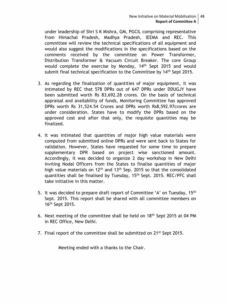
New Initiative on Material Mobilisation Report of Committee A
48
under leadership of Shri S K Mishra, GM, PGCIL comprising representative
from Himachal Pradesh, Madhya Pradesh, IEEMA and REC. This
committee will review the technical specifications of all equipment and
would also suggest the modifications in the specifications based on the
comments received by the committee on Power Transformer,
Distribution Transformer & Vacuum Circuit Breaker. The core Group
would complete the exercise by Monday, 14th Sept 2015 and would
submit final technical specification to the Committee by 14th Sept 2015.
3. As regarding the finalization of quantities of major equipment, it was
intimated by REC that 578 DPRs out of 647 DPRs under DDUGJY have
been submitted worth Rs 83,692.28 crores. On the basis of technical
appraisal and availability of funds, Monitoring Committee has approved
DPRs worth Rs 31,524.54 Crores and DPRs worth Rs8,592.97crores are
under consideration. States have to modify the DPRs based on the
approved cost and after that only, the requisite quantities may be
finalized.
4. It was intimated that quantities of major high value materials were
computed from submitted online DPRs and were sent back to States for
validation. However, States have requested for some time to prepare
supplementary DPR based on project wise sanctioned amount.
Accordingly, it was decided to organize 2 day workshop in New Delhi
inviting Nodal Officers from the States to finalise quantities of major
high value materials on 12th and 13th Sep. 2015 so that the consolidated
quantities shall be finalised by Tuesday, 15th Sept. 2015. REC/PFC shall
take initiative in this matter.
5. It was decided to prepare draft report of Committee ‘A’ on Tuesday, 15th
Sept. 2015. This report shall be shared with all committee members on
16th Sept 2015.
6. Next meeting of the committee shall be held on 18th Sept 2015 at 04 PM
in REC Office, New Delhi.
7. Final report of the committee shall be submitted on 21st Sept 2015.
Meeting ended with a thanks to the Chair.
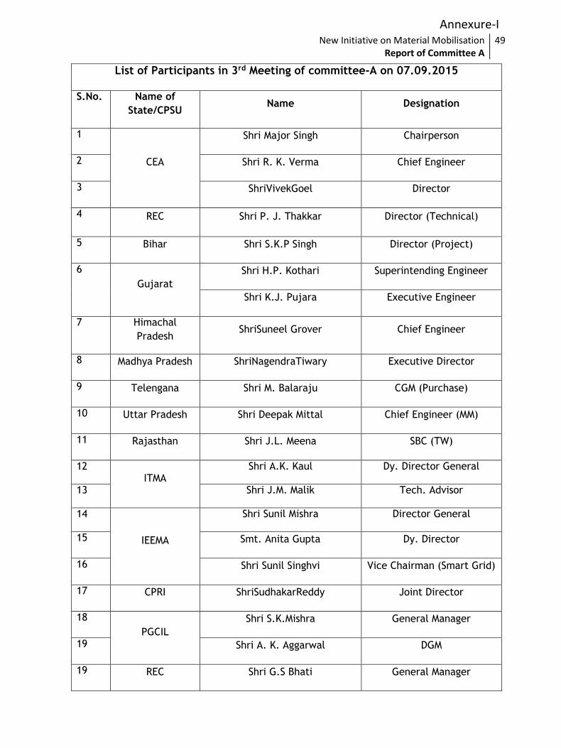
New Initiative on Material Mobilisation Report of Committee A
49
List of Participants in 3rd Meeting of committee-A on 07.09.2015
S.No. Name of
State/CPSU Name Designation
1
CEA
Shri Major Singh Chairperson
2 Shri R. K. Verma Chief Engineer
3 ShriVivekGoel Director
4 REC Shri P. J. Thakkar Director (Technical)
5 Bihar Shri S.K.P Singh Director (Project)
6
Gujarat
Shri H.P. Kothari Superintending Engineer
Shri K.J. Pujara Executive Engineer
7 Himachal
Pradesh ShriSuneel Grover Chief Engineer
8 Madhya Pradesh ShriNagendraTiwary Executive Director
9 Telengana Shri M. Balaraju CGM (Purchase)
10 Uttar Pradesh Shri Deepak Mittal Chief Engineer (MM)
11 Rajasthan Shri J.L. Meena SBC (TW)
12 ITMA
Shri A.K. Kaul Dy. Director General
13 Shri J.M. Malik Tech. Advisor
14
IEEMA
Shri Sunil Mishra Director General
15 Smt. Anita Gupta Dy. Director
16 Shri Sunil Singhvi Vice Chairman (Smart Grid)
17 CPRI ShriSudhakarReddy Joint Director
18
PGCIL
Shri S.K.Mishra General Manager
19 Shri A. K. Aggarwal DGM
19 REC Shri G.S Bhati General Manager
Annexure-I
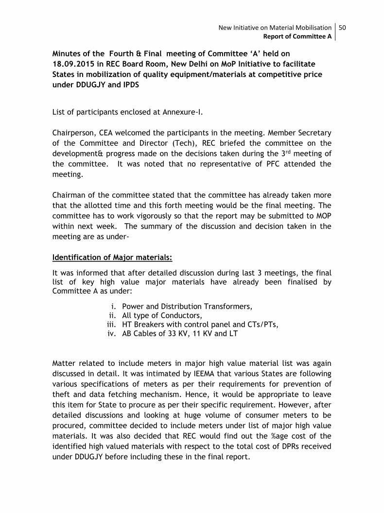
New Initiative on Material Mobilisation Report of Committee A
50
Minutes of the Fourth & Final meeting of Committee ‘A’ held on
18.09.2015 in REC Board Room, New Delhi on MoP Initiative to facilitate
States in mobilization of quality equipment/materials at competitive price
under DDUGJY and IPDS
List of participants enclosed at Annexure-I.
Chairperson, CEA welcomed the participants in the meeting. Member Secretary
of the Committee and Director (Tech), REC briefed the committee on the
development& progress made on the decisions taken during the 3rd meeting of
the committee. It was noted that no representative of PFC attended the
meeting.
Chairman of the committee stated that the committee has already taken more
that the allotted time and this forth meeting would be the final meeting. The
committee has to work vigorously so that the report may be submitted to MOP
within next week. The summary of the discussion and decision taken in the
meeting are as under-
Identification of Major materials:
It was informed that after detailed discussion during last 3 meetings, the final list of key high value major materials have already been finalised by Committee A as under:
i. Power and Distribution Transformers, ii. All type of Conductors, iii. HT Breakers with control panel and CTs/PTs, iv. AB Cables of 33 KV, 11 KV and LT
Matter related to include meters in major high value material list was again
discussed in detail. It was intimated by IEEMA that various States are following
various specifications of meters as per their requirements for prevention of
theft and data fetching mechanism. Hence, it would be appropriate to leave
this item for State to procure as per their specific requirement. However, after
detailed discussions and looking at huge volume of consumer meters to be
procured, committee decided to include meters under list of major high value
materials. It was also decided that REC would find out the %age cost of the
identified high valued materials with respect to the total cost of DPRs received
under DDUGJY before including these in the final report.
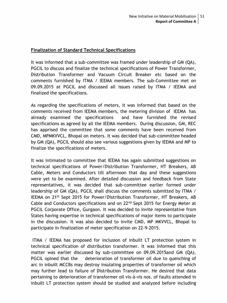
New Initiative on Material Mobilisation Report of Committee A
51
Finalization of Standard Technical Specifications
It was informed that a sub-committee was framed under leadership of GM (QA),
PGCIL to discuss and finalize the technical specifications of Power Transformer,
Distribution Transformer and Vacuum Circuit Breaker etc based on the
comments furnished by ITMA / IEEMA members. The sub-Committee met on
09.09.2015 at PGCIL and discussed all issues raised by ITMA / IEEMA and
finalized the specifications.
As regarding the specifications of meters, it was informed that based on the
comments received from IEEMA members, the metering division of IEEMA has
already examined the specifications and have furnished the revised
specifications as agreed by all the IEEMA members. During discussion, GM, REC
has apprised the committee that some comments have been received from
CMD, MPMKVVCL, Bhopal on meters. It was decided that sub-committee headed
by GM (QA), PGCIL should also see various suggestions given by IEEMA and MP to
finalize the specifications of meters.
It was intimated to committee that IEEMA has again submitted suggestions on
technical specifications of Power/Distribution Transformer, HT Breakers, AB
Cable, Meters and Conductors till afternoon that day and these suggestions
were yet to be examined. After detailed discussion and feedback from State
representatives, it was decided that sub-committee earlier formed under
leadership of GM (QA), PGCIL shall discuss the comments submitted by ITMA /
IEEMA on 21st Sept 2015 for Power/Distribution Transformer, HT Breakers, AB
Cable and Conductors specifications and on 22nd Sept 2015 for Energy Meter at
PGCIL Corporate Office, Gurgaon. It was decided to invite representative from
States having expertise in technical specifications of major items to participate
in the discussion. It was also decided to invite CMD, MP MKVVCL, Bhopal to
participate in finalization of meter specification on 22-9-2015.
ITMA / IEEMA has proposed for inclusion of inbuilt LT protection system in
technical specification of distribution transformer. It was informed that this
matter was earlier discussed by sub-committee on 09.09.2015and GM (QA),
PGCIL opined that the deterioration of transformer oil due to quenching of
arc in inbuilt MCCBs may destroy insulating properties of transformer oil which
may further lead to failure of Distribution Transformer. He desired that data
pertaining to deterioration of transformer oil vis-à-vis nos. of faults attended in
inbuilt LT protection system should be studied and analyzed before including
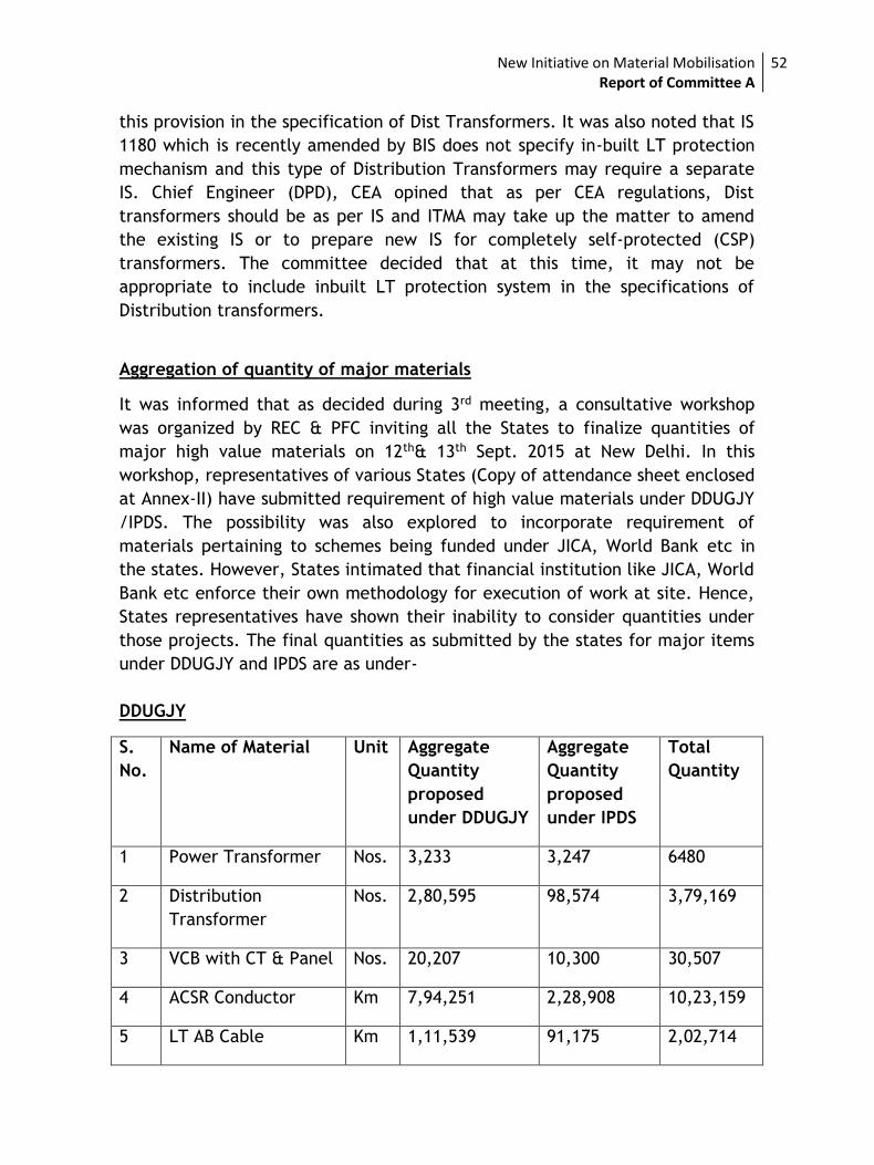
New Initiative on Material Mobilisation Report of Committee A
52
this provision in the specification of Dist Transformers. It was also noted that IS
1180 which is recently amended by BIS does not specify in-built LT protection
mechanism and this type of Distribution Transformers may require a separate
IS. Chief Engineer (DPD), CEA opined that as per CEA regulations, Dist
transformers should be as per IS and ITMA may take up the matter to amend
the existing IS or to prepare new IS for completely self-protected (CSP)
transformers. The committee decided that at this time, it may not be
appropriate to include inbuilt LT protection system in the specifications of
Distribution transformers.
Aggregation of quantity of major materials
It was informed that as decided during 3rd meeting, a consultative workshop
was organized by REC & PFC inviting all the States to finalize quantities of
major high value materials on 12th& 13th Sept. 2015 at New Delhi. In this
workshop, representatives of various States (Copy of attendance sheet enclosed
at Annex-II) have submitted requirement of high value materials under DDUGJY
/IPDS. The possibility was also explored to incorporate requirement of
materials pertaining to schemes being funded under JICA, World Bank etc in
the states. However, States intimated that financial institution like JICA, World
Bank etc enforce their own methodology for execution of work at site. Hence,
States representatives have shown their inability to consider quantities under
those projects. The final quantities as submitted by the states for major items
under DDUGJY and IPDS are as under-
DDUGJY
S.
No.
Name of Material Unit Aggregate
Quantity
proposed
under DDUGJY
Aggregate
Quantity
proposed
under IPDS
Total
Quantity
1 Power Transformer Nos. 3,233 3,247 6480
2 Distribution
Transformer
Nos. 2,80,595 98,574 3,79,169
3 VCB with CT & Panel Nos. 20,207 10,300 30,507
4 ACSR Conductor Km 7,94,251 2,28,908 10,23,159
5 LT AB Cable Km 1,11,539 91,175 2,02,714
New Initiative on Material Mobilisation Report of Committee A
53
However, the details of state wise quantities would be submitted with the final report.
Concluding the discussion, chairman of the committee decided that report of
the committee must be prepared by Tuesday evening i.e. 22nd Sept 2015
incorporating various suggestions received from ITMA / IEEMA & States and the
decisions taken by the sub-committee, thereof. These reports shall be shared
with State representatives through email and the comments from States shall
be invited by Thursday i.e. 24th Sept 2015 so that the Final Report may be
submitted to the Ministry by Thursday i.e. 24th Sept 2015 positively. It was
decided that finalized technical specification of major high value materials
would be Annexure to the report along with uploading on website of
DDUGJY/IPDS.
The meeting ended with a thanks to the chair.
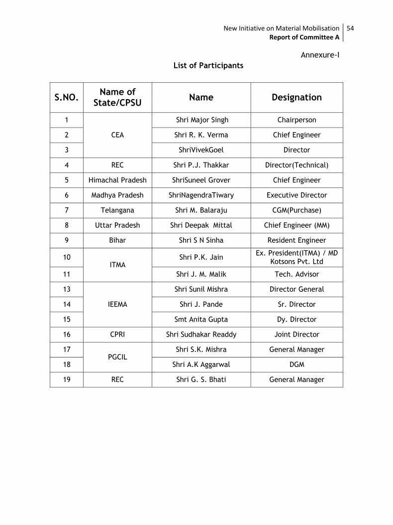
New Initiative on Material Mobilisation Report of Committee A
54
Annexure-I
List of Participants
S.NO. Name of
State/CPSU Name Designation
1
CEA
Shri Major Singh Chairperson
2 Shri R. K. Verma Chief Engineer
3 ShriVivekGoel Director
4 REC Shri P.J. Thakkar Director(Technical)
5 Himachal Pradesh ShriSuneel Grover Chief Engineer
6 Madhya Pradesh ShriNagendraTiwary Executive Director
7 Telangana Shri M. Balaraju CGM(Purchase)
8 Uttar Pradesh Shri Deepak Mittal Chief Engineer (MM)
9 Bihar Shri S N Sinha Resident Engineer
10 ITMA
Shri P.K. Jain Ex. President(ITMA) / MD
Kotsons Pvt. Ltd
11 Shri J. M. Malik Tech. Advisor
13
IEEMA
Shri Sunil Mishra Director General
14 Shri J. Pande Sr. Director
15 Smt Anita Gupta Dy. Director
16 CPRI Shri Sudhakar Readdy Joint Director
17 PGCIL
Shri S.K. Mishra General Manager
18 Shri A.K Aggarwal DGM
19 REC Shri G. S. Bhati General Manager
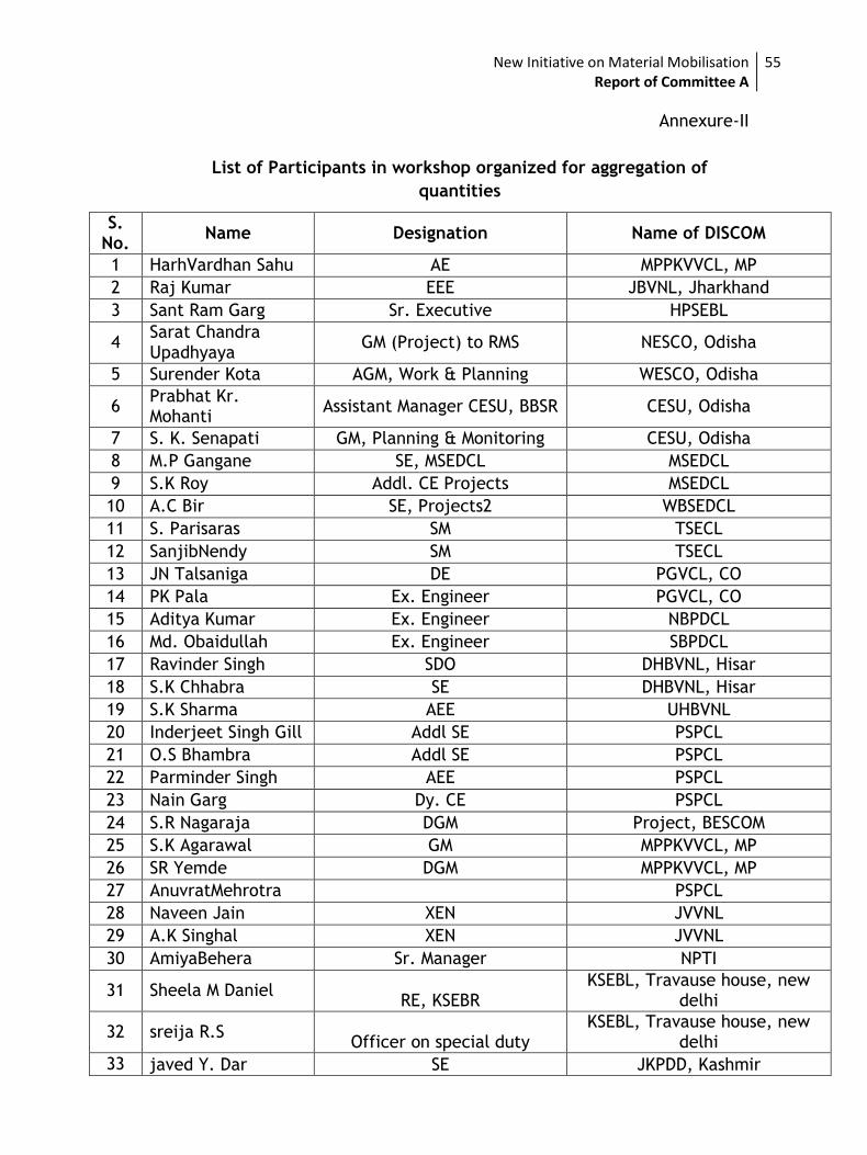
New Initiative on Material Mobilisation Report of Committee A
55
Annexure-II
List of Participants in workshop organized for aggregation of
quantities
S. No.
Name Designation Name of DISCOM
1 HarhVardhan Sahu AE MPPKVVCL, MP
2 Raj Kumar EEE JBVNL, Jharkhand
3 Sant Ram Garg Sr. Executive HPSEBL
4 Sarat Chandra Upadhyaya
GM (Project) to RMS NESCO, Odisha
5 Surender Kota AGM, Work & Planning WESCO, Odisha
6 Prabhat Kr. Mohanti
Assistant Manager CESU, BBSR CESU, Odisha
7 S. K. Senapati GM, Planning & Monitoring CESU, Odisha
8 M.P Gangane SE, MSEDCL MSEDCL
9 S.K Roy Addl. CE Projects MSEDCL
10 A.C Bir SE, Projects2 WBSEDCL
11 S. Parisaras SM TSECL
12 SanjibNendy SM TSECL
13 JN Talsaniga DE PGVCL, CO
14 PK Pala Ex. Engineer PGVCL, CO
15 Aditya Kumar Ex. Engineer NBPDCL
16 Md. Obaidullah Ex. Engineer SBPDCL
17 Ravinder Singh SDO DHBVNL, Hisar
18 S.K Chhabra SE DHBVNL, Hisar
19 S.K Sharma AEE UHBVNL
20 Inderjeet Singh Gill Addl SE PSPCL
21 O.S Bhambra Addl SE PSPCL
22 Parminder Singh AEE PSPCL
23 Nain Garg Dy. CE PSPCL
24 S.R Nagaraja DGM Project, BESCOM
25 S.K Agarawal GM MPPKVVCL, MP
26 SR Yemde DGM MPPKVVCL, MP
27 AnuvratMehrotra PSPCL
28 Naveen Jain XEN JVVNL
29 A.K Singhal XEN JVVNL
30 AmiyaBehera Sr. Manager NPTI
31 Sheela M Daniel RE, KSEBR
KSEBL, Travause house, new delhi
32 sreija R.S Officer on special duty
KSEBL, Travause house, new delhi
33 javed Y. Dar SE JKPDD, Kashmir
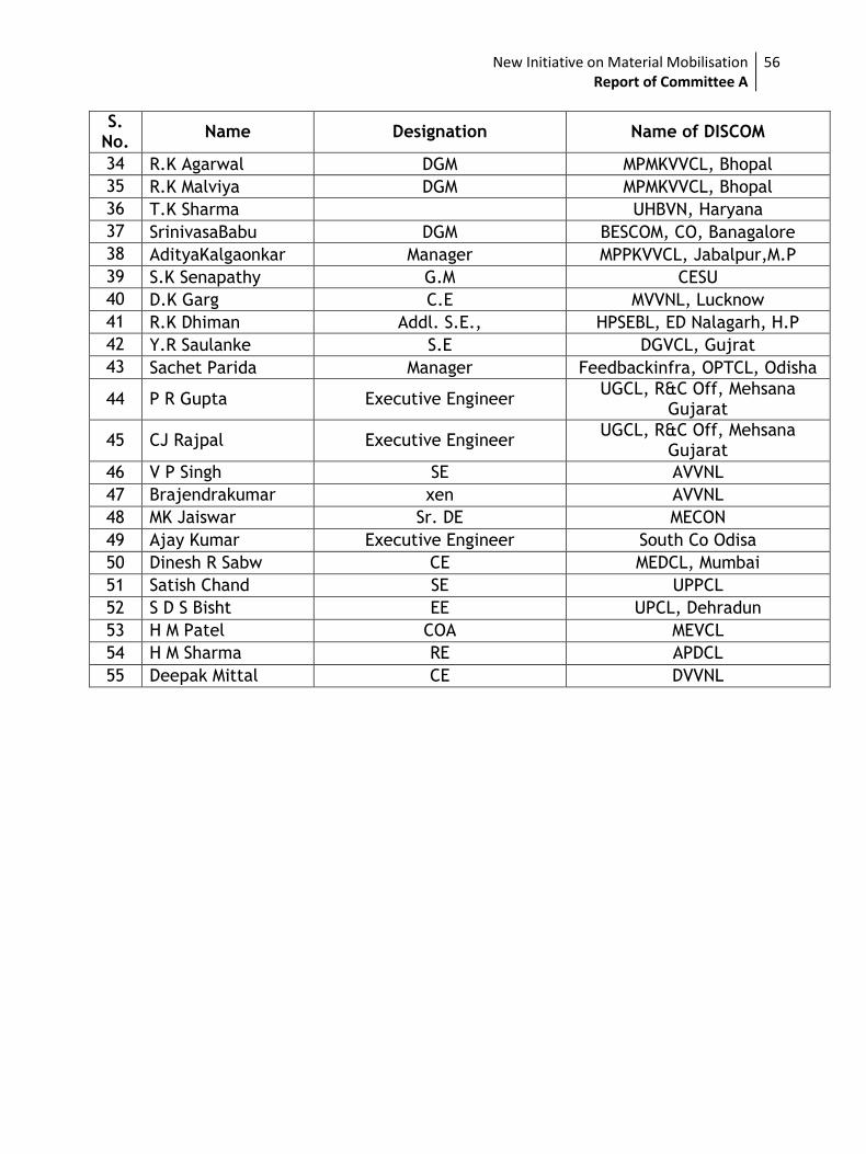
New Initiative on Material Mobilisation Report of Committee A
56
S. No.
Name Designation Name of DISCOM
34 R.K Agarwal DGM MPMKVVCL, Bhopal
35 R.K Malviya DGM MPMKVVCL, Bhopal
36 T.K Sharma UHBVN, Haryana
37 SrinivasaBabu DGM BESCOM, CO, Banagalore
38 AdityaKalgaonkar Manager MPPKVVCL, Jabalpur,M.P
39 S.K Senapathy G.M CESU
40 D.K Garg C.E MVVNL, Lucknow
41 R.K Dhiman Addl. S.E., HPSEBL, ED Nalagarh, H.P
42 Y.R Saulanke S.E DGVCL, Gujrat
43 Sachet Parida Manager Feedbackinfra, OPTCL, Odisha
44 P R Gupta Executive Engineer UGCL, R&C Off, Mehsana
Gujarat
45 CJ Rajpal Executive Engineer UGCL, R&C Off, Mehsana
Gujarat
46 V P Singh SE AVVNL
47 Brajendrakumar xen AVVNL
48 MK Jaiswar Sr. DE MECON
49 Ajay Kumar Executive Engineer South Co Odisa
50 Dinesh R Sabw CE MEDCL, Mumbai
51 Satish Chand SE UPPCL
52 S D S Bisht EE UPCL, Dehradun
53 H M Patel COA MEVCL
54 H M Sharma RE APDCL
55 Deepak Mittal CE DVVNL
New Initiative on Material Mobilisation Report of Committee A
57
Annexure-III
Details of
Per Unit Rates
&
Weightage of
Key High Value Materials
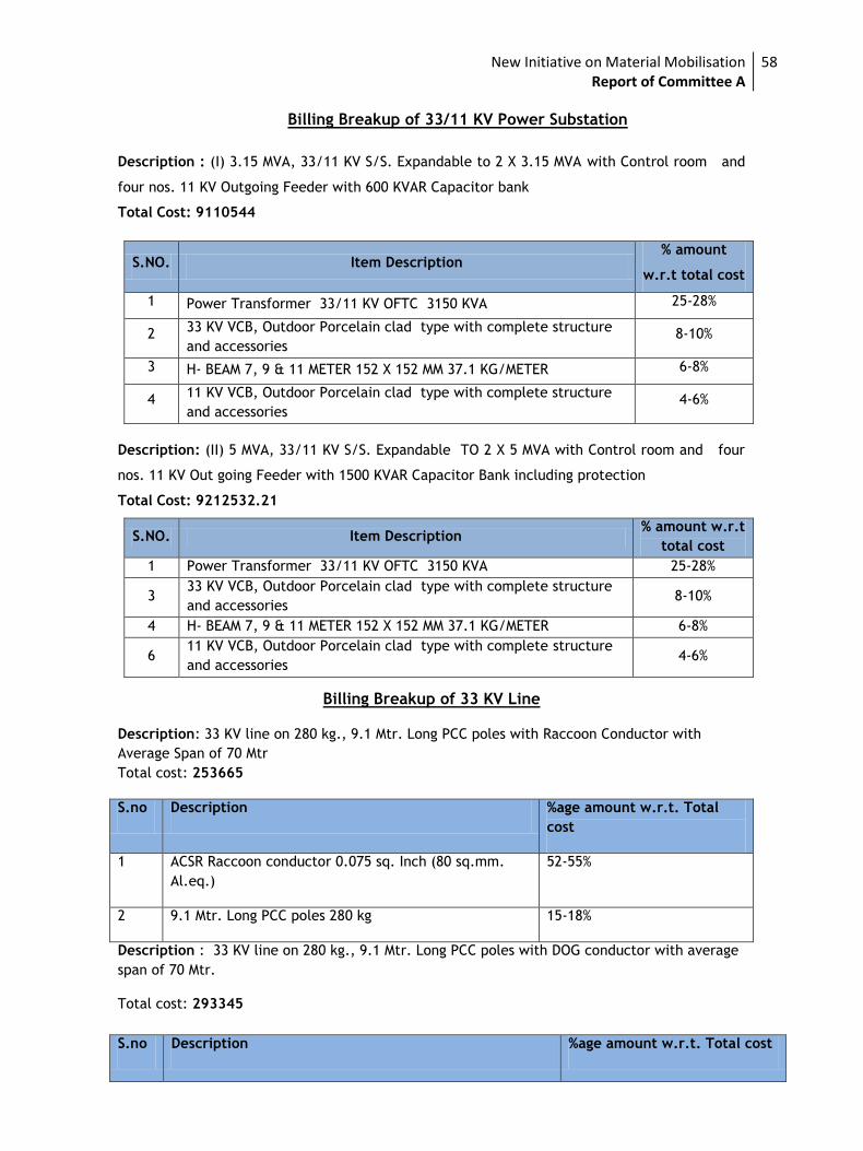
New Initiative on Material Mobilisation Report of Committee A
58
Billing Breakup of 33/11 KV Power Substation
Description : (I) 3.15 MVA, 33/11 KV S/S. Expandable to 2 X 3.15 MVA with Control room and
four nos. 11 KV Outgoing Feeder with 600 KVAR Capacitor bank
Total Cost: 9110544
S.NO. Item Description % amount
w.r.t total cost
1 Power Transformer 33/11 KV OFTC 3150 KVA 25-28%
2 33 KV VCB, Outdoor Porcelain clad type with complete structure
and accessories 8-10%
3 H- BEAM 7, 9 & 11 METER 152 X 152 MM 37.1 KG/METER 6-8%
4 11 KV VCB, Outdoor Porcelain clad type with complete structure
and accessories 4-6%
Description: (II) 5 MVA, 33/11 KV S/S. Expandable TO 2 X 5 MVA with Control room and four
nos. 11 KV Out going Feeder with 1500 KVAR Capacitor Bank including protection
Total Cost: 9212532.21
S.NO. Item Description % amount w.r.t
total cost
1 Power Transformer 33/11 KV OFTC 3150 KVA 25-28%
3 33 KV VCB, Outdoor Porcelain clad type with complete structure
and accessories 8-10%
4 H- BEAM 7, 9 & 11 METER 152 X 152 MM 37.1 KG/METER 6-8%
6 11 KV VCB, Outdoor Porcelain clad type with complete structure
and accessories 4-6%
Billing Breakup of 33 KV Line
Description: 33 KV line on 280 kg., 9.1 Mtr. Long PCC poles with Raccoon Conductor with
Average Span of 70 Mtr
Total cost: 253665
S.no Description %age amount w.r.t. Total
cost
1 ACSR Raccoon conductor 0.075 sq. Inch (80 sq.mm.
Al.eq.)
52-55%
2 9.1 Mtr. Long PCC poles 280 kg 15-18%
Description : 33 KV line on 280 kg., 9.1 Mtr. Long PCC poles with DOG conductor with average
span of 70 Mtr.
Total cost: 293345
S.no Description %age amount w.r.t. Total cost
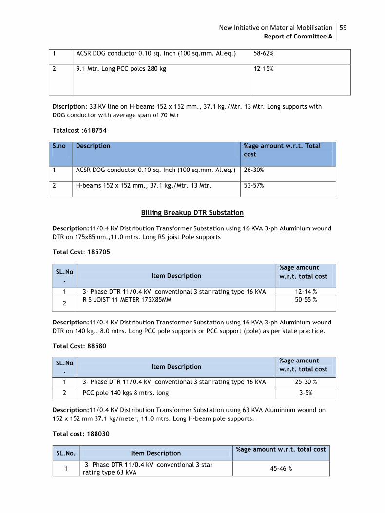
New Initiative on Material Mobilisation Report of Committee A
59
1 ACSR DOG conductor 0.10 sq. Inch (100 sq.mm. Al.eq.) 58-62%
2 9.1 Mtr. Long PCC poles 280 kg 12-15%
Discription: 33 KV line on H-beams 152 x 152 mm., 37.1 kg./Mtr. 13 Mtr. Long supports with
DOG conductor with average span of 70 Mtr
Totalcost :618754
S.no Description %age amount w.r.t. Total
cost
1 ACSR DOG conductor 0.10 sq. Inch (100 sq.mm. Al.eq.) 26-30%
2 H-beams 152 x 152 mm., 37.1 kg./Mtr. 13 Mtr. 53-57%
Billing Breakup DTR Substation
Description:11/0.4 KV Distribution Transformer Substation using 16 KVA 3-ph Aluminium wound
DTR on 175x85mm.,11.0 mtrs. Long RS joist Pole supports
Total Cost: 185705
SL.No.
Item Description
%age amount
w.r.t. total cost
1 3- Phase DTR 11/0.4 kV conventional 3 star rating type 16 kVA 12-14 %
2 R S JOIST 11 METER 175X85MM 50-55 %
Description:11/0.4 KV Distribution Transformer Substation using 16 KVA 3-ph Aluminium wound
DTR on 140 kg., 8.0 mtrs. Long PCC pole supports or PCC support (pole) as per state practice.
Total Cost: 88580
SL.No.
Item Description %age amount
w.r.t. total cost
1 3- Phase DTR 11/0.4 kV conventional 3 star rating type 16 kVA 25-30 %
2 PCC pole 140 kgs 8 mtrs. long 3-5%
Description:11/0.4 KV Distribution Transformer Substation using 63 KVA Aluminium wound on
152 x 152 mm 37.1 kg/meter, 11.0 mtrs. Long H-beam pole supports.
Total cost: 188030
SL.No. Item Description %age amount w.r.t. total cost
1 3- Phase DTR 11/0.4 kV conventional 3 star rating type 63 kVA
45-46 %
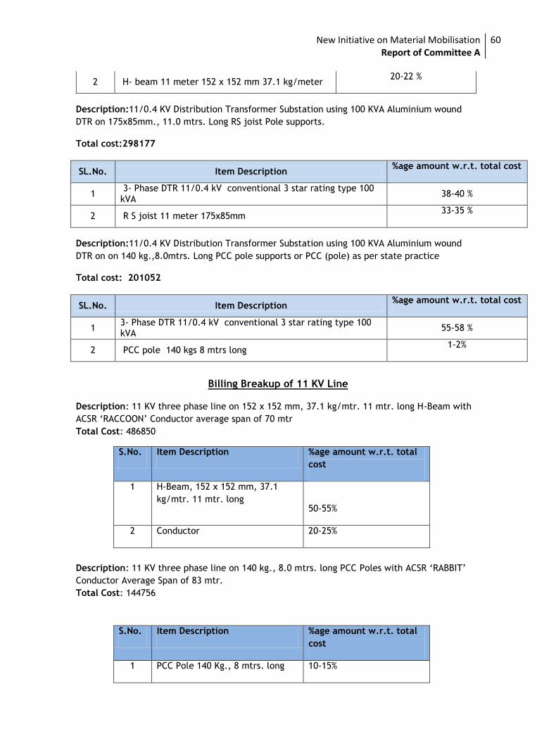
New Initiative on Material Mobilisation Report of Committee A
60
2 H- beam 11 meter 152 x 152 mm 37.1 kg/meter 20-22 %
Description:11/0.4 KV Distribution Transformer Substation using 100 KVA Aluminium wound
DTR on 175x85mm., 11.0 mtrs. Long RS joist Pole supports.
Total cost:298177
SL.No. Item Description %age amount w.r.t. total cost
1 3- Phase DTR 11/0.4 kV conventional 3 star rating type 100 kVA
38-40 %
2 R S joist 11 meter 175x85mm 33-35 %
Description:11/0.4 KV Distribution Transformer Substation using 100 KVA Aluminium wound
DTR on on 140 kg.,8.0mtrs. Long PCC pole supports or PCC (pole) as per state practice
Total cost: 201052
SL.No. Item Description %age amount w.r.t. total cost
1 3- Phase DTR 11/0.4 kV conventional 3 star rating type 100 kVA
55-58 %
2 PCC pole 140 kgs 8 mtrs long 1-2%
Billing Breakup of 11 KV Line
Description: 11 KV three phase line on 152 x 152 mm, 37.1 kg/mtr. 11 mtr. long H-Beam with
ACSR ‘RACCOON’ Conductor average span of 70 mtr
Total Cost: 486850
S.No. Item Description %age amount w.r.t. total
cost
1 H-Beam, 152 x 152 mm, 37.1
kg/mtr. 11 mtr. long
50-55%
2 Conductor 20-25%
Description: 11 KV three phase line on 140 kg., 8.0 mtrs. long PCC Poles with ACSR ‘RABBIT’
Conductor Average Span of 83 mtr.
Total Cost: 144756
S.No. Item Description %age amount w.r.t. total
cost
1 PCC Pole 140 Kg., 8 mtrs. long 10-15%
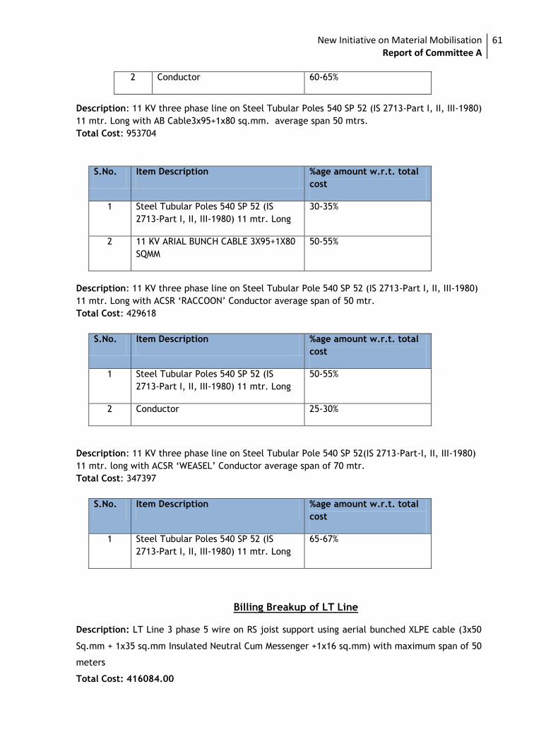
New Initiative on Material Mobilisation Report of Committee A
61
2 Conductor 60-65%
Description: 11 KV three phase line on Steel Tubular Poles 540 SP 52 (IS 2713-Part I, II, III-1980)
11 mtr. Long with AB Cable3x95+1x80 sq.mm. average span 50 mtrs.
Total Cost: 953704
S.No. Item Description %age amount w.r.t. total
cost
1 Steel Tubular Poles 540 SP 52 (IS
2713-Part I, II, III-1980) 11 mtr. Long
30-35%
2 11 KV ARIAL BUNCH CABLE 3X95+1X80
SQMM
50-55%
Description: 11 KV three phase line on Steel Tubular Pole 540 SP 52 (IS 2713-Part I, II, III-1980)
11 mtr. Long with ACSR ‘RACCOON’ Conductor average span of 50 mtr.
Total Cost: 429618
S.No. Item Description %age amount w.r.t. total
cost
1 Steel Tubular Poles 540 SP 52 (IS
2713-Part I, II, III-1980) 11 mtr. Long
50-55%
2 Conductor 25-30%
Description: 11 KV three phase line on Steel Tubular Pole 540 SP 52(IS 2713-Part-I, II, III-1980)
11 mtr. long with ACSR ‘WEASEL’ Conductor average span of 70 mtr.
Total Cost: 347397
S.No. Item Description %age amount w.r.t. total
cost
1 Steel Tubular Poles 540 SP 52 (IS
2713-Part I, II, III-1980) 11 mtr. Long
65-67%
Billing Breakup of LT Line
Description: LT Line 3 phase 5 wire on RS joist support using aerial bunched XLPE cable (3x50
Sq.mm + 1x35 sq.mm Insulated Neutral Cum Messenger +1x16 sq.mm) with maximum span of 50
meters
Total Cost: 416084.00
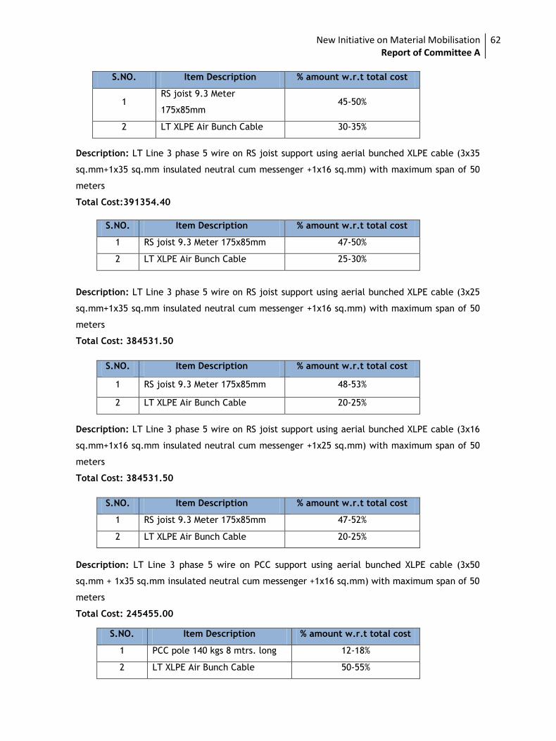
New Initiative on Material Mobilisation Report of Committee A
62
S.NO. Item Description % amount w.r.t total cost
1 RS joist 9.3 Meter
175x85mm 45-50%
2 LT XLPE Air Bunch Cable 30-35%
Description: LT Line 3 phase 5 wire on RS joist support using aerial bunched XLPE cable (3x35
sq.mm+1x35 sq.mm insulated neutral cum messenger +1x16 sq.mm) with maximum span of 50
meters
Total Cost:391354.40
S.NO. Item Description % amount w.r.t total cost
1 RS joist 9.3 Meter 175x85mm 47-50%
2 LT XLPE Air Bunch Cable 25-30%
Description: LT Line 3 phase 5 wire on RS joist support using aerial bunched XLPE cable (3x25
sq.mm+1x35 sq.mm insulated neutral cum messenger +1x16 sq.mm) with maximum span of 50
meters
Total Cost: 384531.50
S.NO. Item Description % amount w.r.t total cost
1 RS joist 9.3 Meter 175x85mm 48-53%
2 LT XLPE Air Bunch Cable 20-25%
Description: LT Line 3 phase 5 wire on RS joist support using aerial bunched XLPE cable (3x16
sq.mm+1x16 sq.mm insulated neutral cum messenger +1x25 sq.mm) with maximum span of 50
meters
Total Cost: 384531.50
S.NO. Item Description % amount w.r.t total cost
1 RS joist 9.3 Meter 175x85mm 47-52%
2 LT XLPE Air Bunch Cable 20-25%
Description: LT Line 3 phase 5 wire on PCC support using aerial bunched XLPE cable (3x50
sq.mm + 1x35 sq.mm insulated neutral cum messenger +1x16 sq.mm) with maximum span of 50
meters
Total Cost: 245455.00
S.NO. Item Description % amount w.r.t total cost
1 PCC pole 140 kgs 8 mtrs. long 12-18%
2 LT XLPE Air Bunch Cable 50-55%
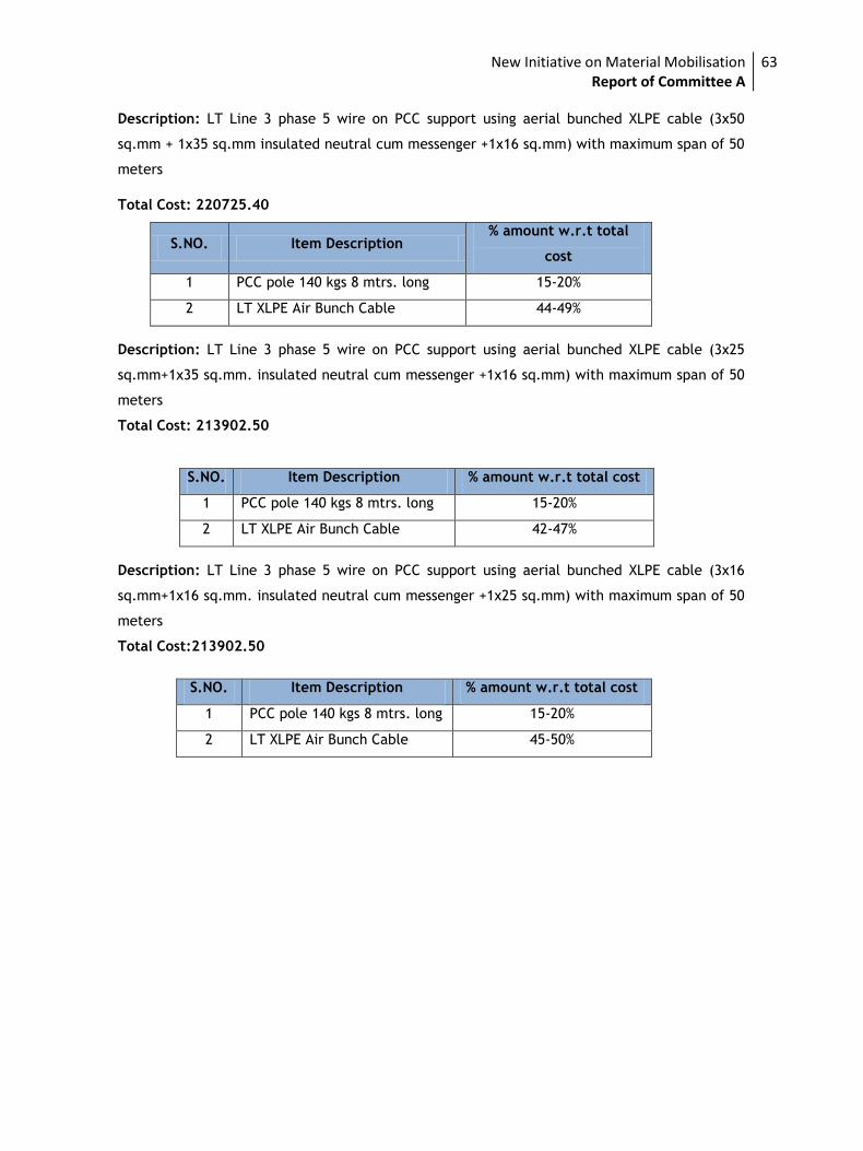
New Initiative on Material Mobilisation Report of Committee A
63
Description: LT Line 3 phase 5 wire on PCC support using aerial bunched XLPE cable (3x50
sq.mm + 1x35 sq.mm insulated neutral cum messenger +1x16 sq.mm) with maximum span of 50
meters
Total Cost: 220725.40
S.NO. Item Description % amount w.r.t total
cost
1 PCC pole 140 kgs 8 mtrs. long 15-20%
2 LT XLPE Air Bunch Cable 44-49%
Description: LT Line 3 phase 5 wire on PCC support using aerial bunched XLPE cable (3x25
sq.mm+1x35 sq.mm. insulated neutral cum messenger +1x16 sq.mm) with maximum span of 50
meters
Total Cost: 213902.50
S.NO. Item Description % amount w.r.t total cost
1 PCC pole 140 kgs 8 mtrs. long 15-20%
2 LT XLPE Air Bunch Cable 42-47%
Description: LT Line 3 phase 5 wire on PCC support using aerial bunched XLPE cable (3x16
sq.mm+1x16 sq.mm. insulated neutral cum messenger +1x25 sq.mm) with maximum span of 50
meters
Total Cost:213902.50
S.NO. Item Description % amount w.r.t total cost
1 PCC pole 140 kgs 8 mtrs. long 15-20%
2 LT XLPE Air Bunch Cable 45-50%
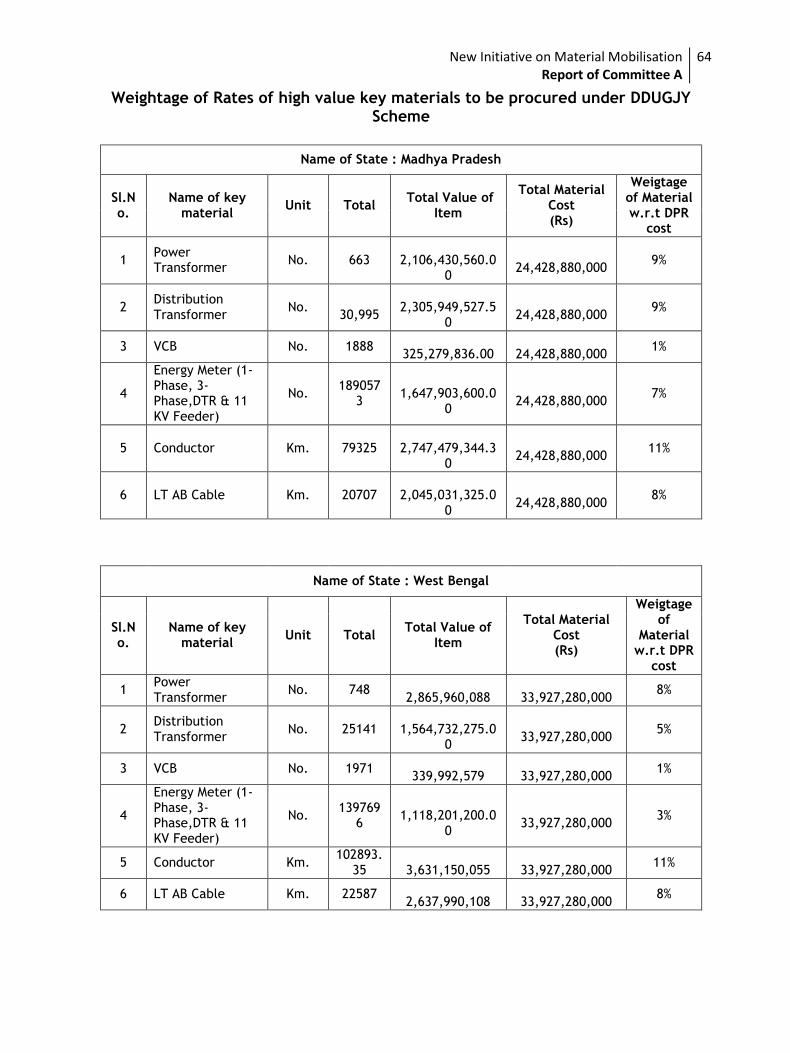
New Initiative on Material Mobilisation Report of Committee A
64
Weightage of Rates of high value key materials to be procured under DDUGJY Scheme
Name of State : Madhya Pradesh
Sl.No.
Name of key material
Unit Total Total Value of
Item
Total Material Cost (Rs)
Weigtage of Material w.r.t DPR
cost
1 Power Transformer
No. 663
2,106,430,560.00
24,428,880,000
9%
2 Distribution Transformer
No.
30,995
2,305,949,527.5
0
24,428,880,000
9%
3 VCB No. 1888
325,279,836.00
24,428,880,000 1%
4
Energy Meter (1-Phase, 3-Phase,DTR & 11 KV Feeder)
No. 189057
3
1,647,903,600.0
0
24,428,880,000
7%
5 Conductor Km. 79325
2,747,479,344.30
24,428,880,000
11%
6 LT AB Cable Km. 20707
2,045,031,325.00
24,428,880,000
8%
Name of State : West Bengal
Sl.No.
Name of key material
Unit Total Total Value of
Item
Total Material Cost (Rs)
Weigtage of
Material w.r.t DPR
cost
1 Power Transformer
No. 748
2,865,960,088
33,927,280,000 8%
2 Distribution Transformer
No. 25141
1,564,732,275.00
33,927,280,000
5%
3 VCB No. 1971
339,992,579
33,927,280,000 1%
4
Energy Meter (1-Phase, 3-Phase,DTR & 11 KV Feeder)
No. 139769
6
1,118,201,200.0
0
33,927,280,000
3%
5 Conductor Km. 102893.
35
3,631,150,055
33,927,280,000 11%
6 LT AB Cable Km. 22587
2,637,990,108
33,927,280,000 8%
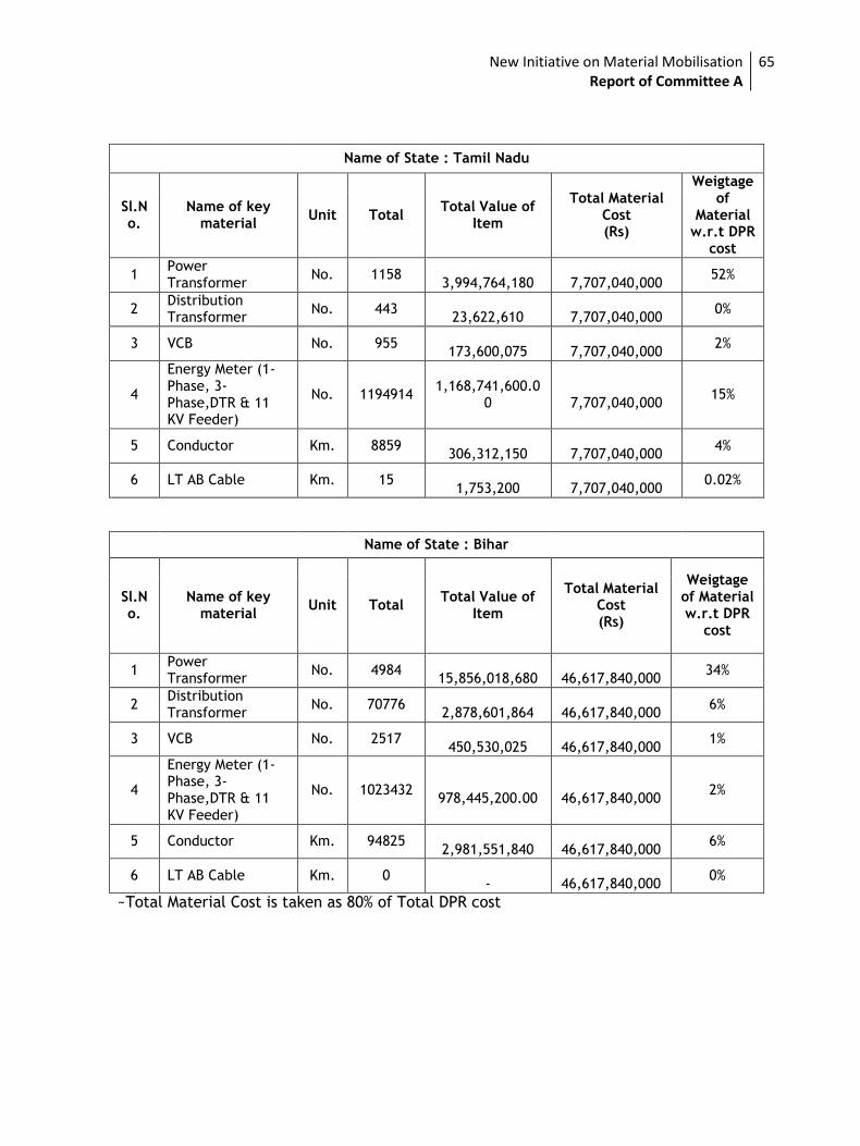
New Initiative on Material Mobilisation Report of Committee A
65
~Total Material Cost is taken as 80% of Total DPR cost
Name of State : Tamil Nadu
Sl.No.
Name of key material
Unit Total Total Value of
Item
Total Material Cost (Rs)
Weigtage of
Material w.r.t DPR
cost
1 Power Transformer
No. 1158
3,994,764,180
7,707,040,000 52%
2 Distribution Transformer
No. 443
23,622,610
7,707,040,000 0%
3 VCB No. 955
173,600,075
7,707,040,000 2%
4
Energy Meter (1-Phase, 3-Phase,DTR & 11 KV Feeder)
No. 1194914 1,168,741,600.0
0
7,707,040,000 15%
5 Conductor Km. 8859
306,312,150
7,707,040,000 4%
6 LT AB Cable Km. 15
1,753,200
7,707,040,000 0.02%
Name of State : Bihar
Sl.No.
Name of key material
Unit Total Total Value of
Item
Total Material Cost (Rs)
Weigtage of Material w.r.t DPR
cost
1 Power Transformer
No. 4984
15,856,018,680
46,617,840,000 34%
2 Distribution Transformer
No. 70776
2,878,601,864
46,617,840,000 6%
3 VCB No. 2517
450,530,025
46,617,840,000 1%
4
Energy Meter (1-Phase, 3-Phase,DTR & 11 KV Feeder)
No. 1023432
978,445,200.00
46,617,840,000 2%
5 Conductor Km. 94825
2,981,551,840
46,617,840,000 6%
6 LT AB Cable Km. 0 -
46,617,840,000
0%
New Initiative on Material Mobilisation Report of Committee A
66
Annexure-IV
Minutes of Meetings
of
Sub-Committee
New Initiative on Material Mobilisation Report of Committee A
67
Minutes of the meeting of held to discuss the comments regarding TS of POWER & Distribution Transformers and VCBs held on 09.09.2015 in POWERGRID, Gurgaon under MoP Initiative to facilitate States in mobilization of quality equipment/materials at competitive price under DDUGJY and IPDS
List of participants is enclosed as Annexure. As decided in the meeting of Committee “A” held on 7.9.15 , the core group consisting of the members from POWERGRID, REC, MP , HP , ITMA and IEEMA met on 9.9.15 in POWERGRID Corporate office , Gurgaon to discuss the comments received on of POWER & Distribution Transformers and VCBs.
The following was discussed: A. 3.15/5/6.3/8/10/12.5 MVA Power Transformers
1. Clause 1.2 Page 1& 7.4.2 Representatives of IEEMA submitted that core material need not be specified since losses have been standardized. They also reiterated that specifying a particular type of core material will increase demand for this type of material leading to higher cost. ITMA member confirmed that there is sufficient availability of HIB grade of CRGO steel and for the transformers above 3.1 5 MVA HIB grade of CRGO can be specified. Accordingly, it was agreed to specify the HIB grade of BIS certified CRGO steel for all transformers above 3.1 5 MVA. 2. Point 22& 29, Clause 2.0 BIL for 11KV winding and bushing were discussed and it was decided to specify 75 kVp (1.2 / 50 microsecond wave shape Impulse) instead of 95 KVp.
3. Point 26, Clause 2.0 Indicated temperature rises for power transformer was discussed. POWERGRID emphasized that lower temperature rise will help in reduction of transformer failure. Therefore, it was decided that the temp rise of 40/45deg C for oil/winding for power transformers will be maintained. 4. Point 30, Clause 2.0 Material of HV & LV Conductor discussed and it was decided that it will be Electrolytic Copper only.
New Initiative on Material Mobilisation Report of Committee A
68
5. Point 31, Clause 2.0 It was decided that no current density in winding shall be specified. 6. Point 32, Clause 2.0 Polarization index was discussed. It was agreed the point, as printed, was not clear due to format of the table. It was further decided that
a) Ratio of megger values at 600 Sec : megger values at 15 Sec will not be less than 1.5
b) Ratio of megger values at 600 Sec : megger values at 60 Sec will not be more than 5
The above will be valid for all the three combinations i.e. HV to LV, HV to Earth and LV to earth 7. Point 21 of clause no-2& Clause 7.4.2 It was decided that the Maximum Flux Density in any part of the core and yoke at rated MVA, rated voltage i.e 33 KV / 11 KV and system frequency of 50 HZ shall be 1.69 Tesla instead of 1.5 Tesla as mentioned in clause 7.4.2. Accordingly, the Maximum flux density at continuous operation at 112.5% of rated voltage and system frequency shall be 1.9 Tesla. Therefore, Point No. 21 of Cl. 2 will be changed to include “ 112.5 % of rated voltage” instead of “rated voltage” 8. Clause 8.2.1.1 Short circuit test will be specified as a “Special Test” instead of “Type Test as per IS 2026.short circuit test. It was also decided that this will be a mandatory test for each design and no exception will be allowed on this issue. 9. Clause 8.2.3, point (xii).
Issued regarding tests on off load tap changer was discussed and it was decided
this will be tested as per IS 2026 instead of IEC: 214/1976 and BS4571/ 1970.
Apart from above, losses and percentage impedance of power transformer were
also discussed and on suggestions of representative of ITMA, it was decided to
specify the same as given below
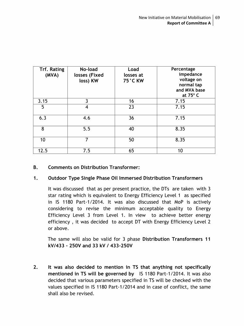
New Initiative on Material Mobilisation Report of Committee A
69
B. Comments on Distribution Transformer:
1. Outdoor Type Single Phase Oil Immersed Distribution Transformers
It was discussed that as per present practice, the DTs are taken with 3
star rating which is equivalent to Energy Efficiency Level 1 as specified
in IS 1180 Part-1/2014. It was also discussed that MoP is actively
considering to revise the minimum acceptable quality to Energy
Efficiency Level 3 from Level 1. In view to achieve better energy
efficiency , it was decided to accept DT with Energy Efficiency Level 2
or above.
The same will also be valid for 3 phase Distribution Transformers 11
kV/433 – 250V and 33 kV / 433-250V
2. It was also decided to mention in TS that anything not specifically
mentioned in TS will be governed by IS 1180 Part-1/2014. It was also
decided that various parameters specified in TS will be checked with the
values specified in IS 1180 Part-1/2014 and in case of conflict, the same
shall also be revised.
Trf. Rating (MVA)
No-load losses (Fixed
loss) KW
Load losses at 75°C KW
Percentage impedance voltage on normal tap
and MVA base at 75o C
3.15 3 16 7.15
5 4 23 7.15
6.3 4.6 36 7.15
8 5.5 40 8.35
10 7 50 8.35
12.5 7.5 65 10
New Initiative on Material Mobilisation Report of Committee A
70
3. Internal LTCB in DT: it was discussed that if a LTCB is provided internal
to DT i.e oil immerged in tank, there are chance of oil contamination
due to frequent operations of this LTCB which may lead to DT failure. To
avoid this, it was decided to provide a LTCB/MCCB external to DT.
C. VCB:
Interrupting capacity of 1500MVA and short circuit rating of 25KA for 3
sec for both 11kv and 33kv vacuum circuit breaker is mentioned at S.No-
v & viii of clause.2 . It was discussed and decided to delete Interrupting
capacity parameter from specification as it is not required to specify
when short circuit rating is already specified.
GIS and RMU may be required under IPDS scheme and M/s Siemens has
requested to include specification of GIS and RMU in SBD.
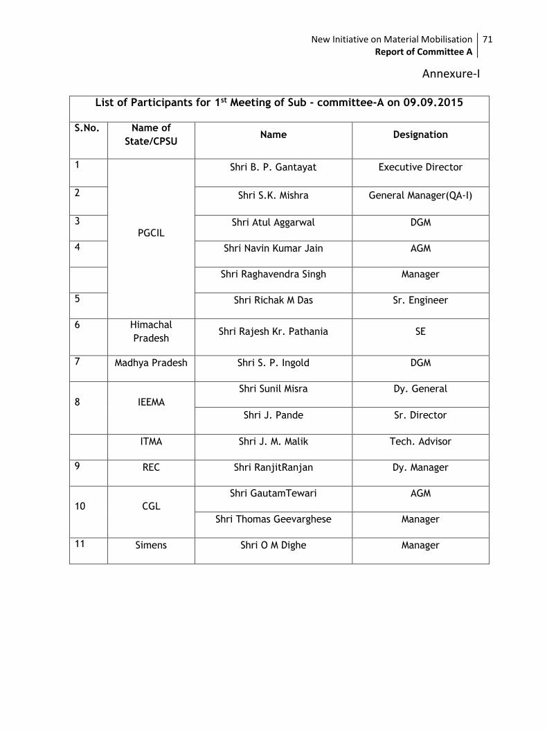
New Initiative on Material Mobilisation Report of Committee A
71
List of Participants for 1st Meeting of Sub - committee-A on 09.09.2015
S.No. Name of
State/CPSU Name Designation
1
PGCIL
Shri B. P. Gantayat Executive Director
2 Shri S.K. Mishra General Manager(QA-I)
3 Shri Atul Aggarwal DGM
4 Shri Navin Kumar Jain AGM
Shri Raghavendra Singh Manager
5 Shri Richak M Das Sr. Engineer
6 Himachal
Pradesh Shri Rajesh Kr. Pathania SE
7 Madhya Pradesh Shri S. P. Ingold DGM
8 IEEMA
Shri Sunil Misra Dy. General
Shri J. Pande Sr. Director
ITMA Shri J. M. Malik Tech. Advisor
9 REC Shri RanjitRanjan Dy. Manager
10 CGL
Shri GautamTewari AGM
Shri Thomas Geevarghese Manager
11 Simens Shri O M Dighe Manager
Annexure-I
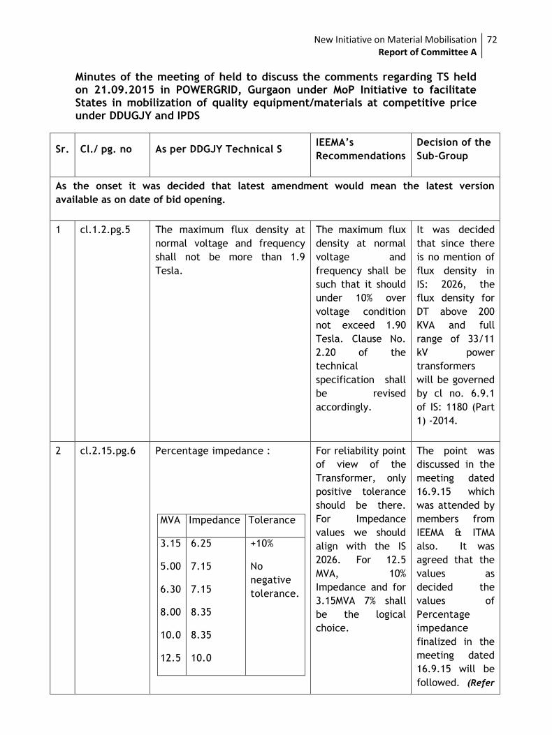
New Initiative on Material Mobilisation Report of Committee A
72
Minutes of the meeting of held to discuss the comments regarding TS held on 21.09.2015 in POWERGRID, Gurgaon under MoP Initiative to facilitate States in mobilization of quality equipment/materials at competitive price under DDUGJY and IPDS
Sr. Cl./ pg. no As per DDGJY Technical S IEEMA’s
Recommendations
Decision of the
Sub-Group
As the onset it was decided that latest amendment would mean the latest version
available as on date of bid opening.
1 cl.1.2.pg.5 The maximum flux density at
normal voltage and frequency
shall not be more than 1.9
Tesla.
The maximum flux
density at normal
voltage and
frequency shall be
such that it should
under 10% over
voltage condition
not exceed 1.90
Tesla. Clause No.
2.20 of the
technical
specification shall
be revised
accordingly.
It was decided
that since there
is no mention of
flux density in
IS: 2026, the
flux density for
DT above 200
KVA and full
range of 33/11
kV power
transformers
will be governed
by cl no. 6.9.1
of IS: 1180 (Part
1) -2014.
2 cl.2.15.pg.6 Percentage impedance :
MVA Impedance Tolerance
3.15
5.00
6.30
8.00
10.0
12.5
6.25
7.15
7.15
8.35
8.35
10.0
+10%
No
negative
tolerance.
For reliability point
of view of the
Transformer, only
positive tolerance
should be there.
For Impedance
values we should
align with the IS
2026. For 12.5
MVA, 10%
Impedance and for
3.15MVA 7% shall
be the logical
choice.
The point was
discussed in the
meeting dated
16.9.15 which
was attended by
members from
IEEMA & ITMA
also. It was
agreed that the
values as
decided the
values of
Percentage
impedance
finalized in the
meeting dated
16.9.15 will be
followed. (Refer
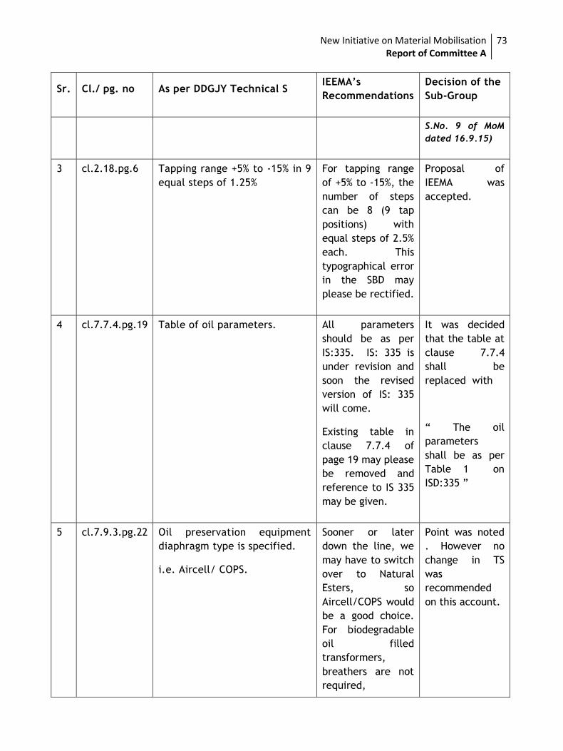
New Initiative on Material Mobilisation Report of Committee A
73
Sr. Cl./ pg. no As per DDGJY Technical S IEEMA’s
Recommendations
Decision of the
Sub-Group
S.No. 9 of MoM
dated 16.9.15)
3 cl.2.18.pg.6 Tapping range +5% to -15% in 9
equal steps of 1.25%
For tapping range
of +5% to -15%, the
number of steps
can be 8 (9 tap
positions) with
equal steps of 2.5%
each. This
typographical error
in the SBD may
please be rectified.
Proposal of
IEEMA was
accepted.
4 cl.7.7.4.pg.19 Table of oil parameters. All parameters
should be as per
IS:335. IS: 335 is
under revision and
soon the revised
version of IS: 335
will come.
Existing table in
clause 7.7.4 of
page 19 may please
be removed and
reference to IS 335
may be given.
It was decided
that the table at
clause 7.7.4
shall be
replaced with
“ The oil
parameters
shall be as per
Table 1 on
ISD:335 ”
5 cl.7.9.3.pg.22 Oil preservation equipment
diaphragm type is specified.
i.e. Aircell/ COPS.
Sooner or later
down the line, we
may have to switch
over to Natural
Esters, so
Aircell/COPS would
be a good choice.
For biodegradable
oil filled
transformers,
breathers are not
required,
Point was noted
. However no
change in TS
was
recommended
on this account.
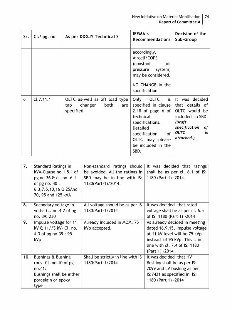
New Initiative on Material Mobilisation Report of Committee A
74
Sr. Cl./ pg. no As per DDGJY Technical S IEEMA’s
Recommendations
Decision of the
Sub-Group
accordingly,
Aircell/COPS
(constant oil
pressure system)
may be considered.
NO CHANGE in the
specification
6 cl.7.11.1 OLTC as-well as off load type
tap changer both are
specified.
Only OLTC is
specified in clause
2.18 of page 6 of
technical
specifications.
Detailed
specification of
OLTC may please
be included in the
SBD.
It was decided
that details of
OLTC would be
included in SBD.
(Draft
specification of
OLTC is
attached.)
7. Standard Ratings in
kVA-Clause no.1.5.1 of
pg no.36 & cl. no. 6.1
of pg no. 40 :
6.3,7.5,10,16 & 25And
70, 95 and 125 kVA
Non-standard ratings should
be avoided. All the ratings in
SBD may be in line with IS:
1180(Part-1)/2014.
It was decided that ratings
shall be as per cl. 6.1 of IS:
1180 (Part 1) -2014.
8. Secondary voltage in
volts- Cl. no.4.2 of pg
no. 39: 230
All voltage should be as per IS
1180:Part-1/2014
It was decided that rated
voltage shall be as per cl. 6.5
of IS: 1180 (Part 1) -2014
9. Impulse voltage for 11
kV & 11/√3 kV- Cl. no.
4.3 of pg no.39 : 95
kVp
Already included in MOM, 75
kVp accepted.
As already decided in meeting
dated 16.9.15, Impulse voltage
at 11 kV level will be 75 kVp
instead of 95 kVp. This is in
line with cl. 7.4 of IS: 1180
(Part 1) -2014
10. Bushings & Bushing
rods- Cl .no.10 of pg
no.41:
Bushings shall be either
porcelain or epoxy
type
Shall be strictly in line with IS
1180:Part-1/2014
It was decided that HV
Bushing shall be as per IS:
2099 and LV bushing as per
IS:7421 as specified in IS:
1180 (Part 1) -2014
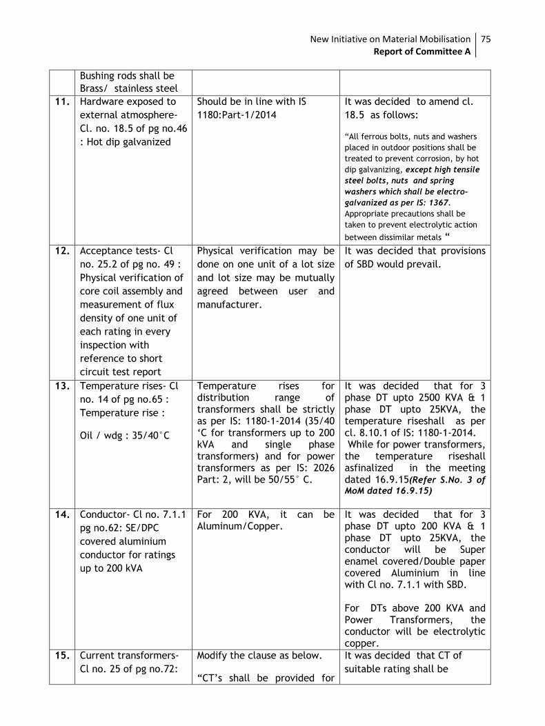
New Initiative on Material Mobilisation Report of Committee A
75
Bushing rods shall be
Brass/ stainless steel
11. Hardware exposed to
external atmosphere-
Cl. no. 18.5 of pg no.46
: Hot dip galvanized
Should be in line with IS
1180:Part-1/2014
It was decided to amend cl.
18.5 as follows:
“All ferrous bolts, nuts and washers
placed in outdoor positions shall be
treated to prevent corrosion, by hot
dip galvanizing, except high tensile
steel bolts, nuts and spring
washers which shall be electro-
galvanized as per IS: 1367.
Appropriate precautions shall be
taken to prevent electrolytic action
between dissimilar metals “
12. Acceptance tests- Cl
no. 25.2 of pg no. 49 :
Physical verification of
core coil assembly and
measurement of flux
density of one unit of
each rating in every
inspection with
reference to short
circuit test report
Physical verification may be
done on one unit of a lot size
and lot size may be mutually
agreed between user and
manufacturer.
It was decided that provisions
of SBD would prevail.
13. Temperature rises- Cl
no. 14 of pg no.65 :
Temperature rise :
Oil / wdg : 35/40°C
Temperature rises for distribution range of transformers shall be strictly as per IS: 1180-1-2014 (35/40 ‘C for transformers up to 200 kVA and single phase transformers) and for power transformers as per IS: 2026 Part: 2, will be 50/55° C.
It was decided that for 3 phase DT upto 2500 KVA & 1 phase DT upto 25KVA, the temperature riseshall as per cl. 8.10.1 of IS: 1180-1-2014. While for power transformers, the temperature riseshall asfinalized in the meeting dated 16.9.15(Refer S.No. 3 of
MoM dated 16.9.15)
14. Conductor- Cl no. 7.1.1
pg no.62: SE/DPC
covered aluminium
conductor for ratings
up to 200 kVA
For 200 KVA, it can be Aluminum/Copper.
It was decided that for 3 phase DT upto 200 KVA & 1 phase DT upto 25KVA, the conductor will be Super enamel covered/Double paper covered Aluminium in line with Cl no. 7.1.1 with SBD. For DTs above 200 KVA and Power Transformers, the conductor will be electrolytic copper.
15. Current transformers-
Cl no. 25 of pg no.72:
Modify the clause as below.
“CT’s shall be provided for
It was decided that CT of
suitable rating shall be
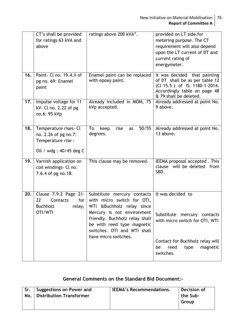
New Initiative on Material Mobilisation Report of Committee A
76
CT’s shall be provided
for ratings 63 kVA and
above
ratings above 200 kVA”. provided on LT side.for
metering purpose. The CT
requirement will also depend
upon the LT current of DT and
current rating of
energymeter.
16. Paint- Cl no. 19.4.ii of
pg no. 69: Enamel
paint
Enamel paint can be replaced with epoxy paint.
It was decided that painting of DT shall be as per table 12 (Cl 15.5 ) of IS: 1180-1-2014. Accordingly table on page 48 & 79 shall be deleted.
17. Impulse voltage for 11
kV- Cl no. 2.22 of pg
no.6: 95 kVp
Already included in MOM, 75 kVp accepted.
Already addressed at point No. 9 above.
18. Temperature rises- Cl
no. 2.26 of pg no.7:
Temperature rise :
Oil / wdg : 40/45 deg C
To keep rise as 50/55 degrees.
Already addressed at point No. 13 above.
19. Varnish application on
coil windings- Cl no.
7.6.4 of pg no.18:
This clause may be removed. IEEMA proposal accepted . This clause will be deleted from SBD.
20. Clause 7.9.2 Page 21-
22 Contacts for
Buchholz relay,
OTI/WTI
Substitute mercury contacts
with micro switch for OTI,
WTI &Buchholz relay since
Mercury is not environment
friendly. Buchholz relay shall
be with reed type magnetic
switches. OTI and WTI shall
have micro switches.
It was decided to
Substitute mercury contacts
with micro switch for OTI, WTI
Contact for Buchholz relay will
be reed type magnetic
switches.
General Comments on the Standard Bid Document:-
Sr.
No.
Suggestions on Power and
Distribution Transformer
IEEMA’s Recommendations. Decision of
the Sub-
Group
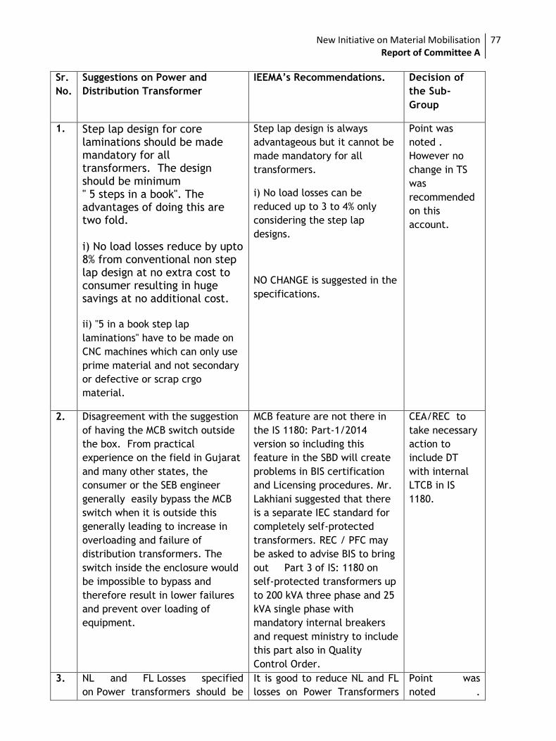
New Initiative on Material Mobilisation Report of Committee A
77
Sr.
No.
Suggestions on Power and
Distribution Transformer
IEEMA’s Recommendations. Decision of
the Sub-
Group
1. Step lap design for core laminations should be made mandatory for all transformers. The design should be minimum " 5 steps in a book". The advantages of doing this are two fold.
i) No load losses reduce by upto 8% from conventional non step lap design at no extra cost to consumer resulting in huge savings at no additional cost.
ii) "5 in a book step lap
laminations" have to be made on
CNC machines which can only use
prime material and not secondary
or defective or scrap crgo
material.
Step lap design is always
advantageous but it cannot be
made mandatory for all
transformers.
i) No load losses can be
reduced up to 3 to 4% only
considering the step lap
designs.
NO CHANGE is suggested in the
specifications.
Point was
noted .
However no
change in TS
was
recommended
on this
account.
2. Disagreement with the suggestion
of having the MCB switch outside
the box. From practical
experience on the field in Gujarat
and many other states, the
consumer or the SEB engineer
generally easily bypass the MCB
switch when it is outside this
generally leading to increase in
overloading and failure of
distribution transformers. The
switch inside the enclosure would
be impossible to bypass and
therefore result in lower failures
and prevent over loading of
equipment.
MCB feature are not there in
the IS 1180: Part-1/2014
version so including this
feature in the SBD will create
problems in BIS certification
and Licensing procedures. Mr.
Lakhiani suggested that there
is a separate IEC standard for
completely self-protected
transformers. REC / PFC may
be asked to advise BIS to bring
out Part 3 of IS: 1180 on
self-protected transformers up
to 200 kVA three phase and 25
kVA single phase with
mandatory internal breakers
and request ministry to include
this part also in Quality
Control Order.
CEA/REC to
take necessary
action to
include DT
with internal
LTCB in IS
1180.
3. NL and FL Losses specified
on Power transformers should be
It is good to reduce NL and FL
losses on Power Transformers
Point was
noted .
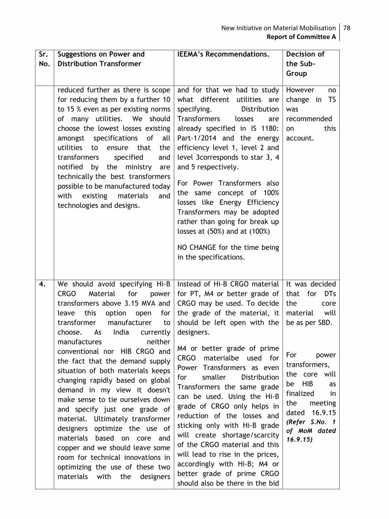
New Initiative on Material Mobilisation Report of Committee A
78
Sr.
No.
Suggestions on Power and
Distribution Transformer
IEEMA’s Recommendations. Decision of
the Sub-
Group
reduced further as there is scope
for reducing them by a further 10
to 15 % even as per existing norms
of many utilities. We should
choose the lowest losses existing
amongst specifications of all
utilities to ensure that the
transformers specified and
notified by the ministry are
technically the best transformers
possible to be manufactured today
with existing materials and
technologies and designs.
and for that we had to study
what different utilities are
specifying. Distribution
Transformers losses are
already specified in IS 1180:
Part-1/2014 and the energy
efficiency level 1, level 2 and
level 3corresponds to star 3, 4
and 5 respectively.
For Power Transformers also
the same concept of 100%
losses like Energy Efficiency
Transformers may be adopted
rather than going for break up
losses at (50%) and at (100%)
NO CHANGE for the time being
in the specifications.
However no
change in TS
was
recommended
on this
account.
4. We should avoid specifying Hi-B
CRGO Material for power
transformers above 3.15 MVA and
leave this option open for
transformer manufacturer to
choose. As India currently
manufactures neither
conventional nor HIB CRGO and
the fact that the demand supply
situation of both materials keeps
changing rapidly based on global
demand in my view it doesn't
make sense to tie ourselves down
and specify just one grade of
material. Ultimately transformer
designers optimize the use of
materials based on core and
copper and we should leave some
room for technical innovations in
optimizing the use of these two
materials with the designers
Instead of Hi-B CRGO material
for PT, M4 or better grade of
CRGO may be used. To decide
the grade of the material, it
should be left open with the
designers.
M4 or better grade of prime
CRGO materialbe used for
Power Transformers as even
for smaller Distribution
Transformers the same grade
can be used. Using the Hi-B
grade of CRGO only helps in
reduction of the losses and
sticking only with Hi-B grade
will create shortage/scarcity
of the CRGO material and this
will lead to rise in the prices,
accordingly with Hi-B; M4 or
better grade of prime CRGO
should also be there in the bid
It was decided
that for DTs
the core
material will
be as per SBD.
For power
transformers,
the core will
be HIB as
finalized in
the meeting
dated 16.9.15
(Refer S.No. 1
of MoM dated
16.9.15)
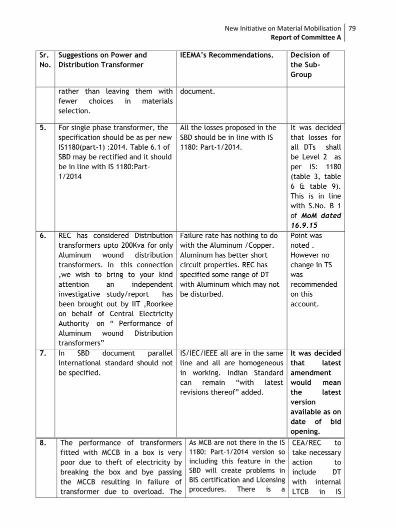
New Initiative on Material Mobilisation Report of Committee A
79
Sr.
No.
Suggestions on Power and
Distribution Transformer
IEEMA’s Recommendations. Decision of
the Sub-
Group
rather than leaving them with
fewer choices in materials
selection.
document.
5. For single phase transformer, the
specification should be as per new
IS1180(part-1) :2014. Table 6.1 of
SBD may be rectified and it should
be in line with IS 1180:Part-
1/2014
All the losses proposed in the
SBD should be in line with IS
1180: Part-1/2014.
It was decided
that losses for
all DTs shall
be Level 2 as
per IS: 1180
(table 3, table
6 & table 9).
This is in line
with S.No. B 1
of MoM dated
16.9.15
6. REC has considered Distribution
transformers upto 200Kva for only
Aluminum wound distribution
transformers. In this connection
,we wish to bring to your kind
attention an independent
investigative study/report has
been brought out by IIT ,Roorkee
on behalf of Central Electricity
Authority on “ Performance of
Aluminum wound Distribution
transformers”
Failure rate has nothing to do
with the Aluminum /Copper.
Aluminum has better short
circuit properties. REC has
specified some range of DT
with Aluminum which may not
be disturbed.
Point was
noted .
However no
change in TS
was
recommended
on this
account.
7. In SBD document parallel
International standard should not
be specified.
IS/IEC/IEEE all are in the same
line and all are homogeneous
in working. Indian Standard
can remain “with latest
revisions thereof” added.
It was decided
that latest
amendment
would mean
the latest
version
available as on
date of bid
opening.
8. The performance of transformers
fitted with MCCB in a box is very
poor due to theft of electricity by
breaking the box and bye passing
the MCCB resulting in failure of
transformer due to overload. The
As MCB are not there in the IS
1180: Part-1/2014 version so
including this feature in the
SBD will create problems in
BIS certification and Licensing
procedures. There is a
CEA/REC to
take necessary
action to
include DT
with internal
LTCB in IS
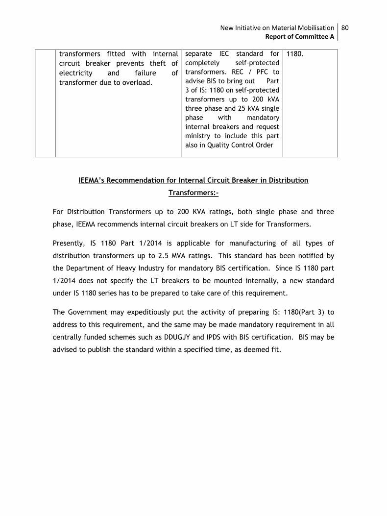
New Initiative on Material Mobilisation Report of Committee A
80
transformers fitted with internal
circuit breaker prevents theft of
electricity and failure of
transformer due to overload.
separate IEC standard for
completely self-protected
transformers. REC / PFC to
advise BIS to bring out Part
3 of IS: 1180 on self-protected
transformers up to 200 kVA
three phase and 25 kVA single
phase with mandatory
internal breakers and request
ministry to include this part
also in Quality Control Order
1180.
IEEMA’s Recommendation for Internal Circuit Breaker in Distribution
Transformers:-
For Distribution Transformers up to 200 KVA ratings, both single phase and three
phase, IEEMA recommends internal circuit breakers on LT side for Transformers.
Presently, IS 1180 Part 1/2014 is applicable for manufacturing of all types of
distribution transformers up to 2.5 MVA ratings. This standard has been notified by
the Department of Heavy Industry for mandatory BIS certification. Since IS 1180 part
1/2014 does not specify the LT breakers to be mounted internally, a new standard
under IS 1180 series has to be prepared to take care of this requirement.
The Government may expeditiously put the activity of preparing IS: 1180(Part 3) to
address to this requirement, and the same may be made mandatory requirement in all
centrally funded schemes such as DDUGJY and IPDS with BIS certification. BIS may be
advised to publish the standard within a specified time, as deemed fit.
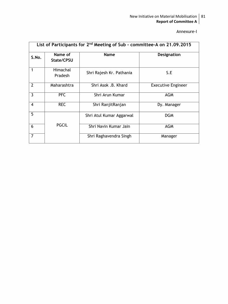
New Initiative on Material Mobilisation Report of Committee A
81
Annexure-I
List of Participants for 2nd Meeting of Sub - committee-A on 21.09.2015
S.No. Name of
State/CPSU
Name Designation
1 Himachal
Pradesh Shri Rajesh Kr. Pathania S.E
2 Maharashtra Shri Asok .B. Khard Executive Engineer
3 PFC Shri Arun Kumar AGM
4 REC Shri RanjitRanjan Dy. Manager
5
PGCIL
Shri Atul Kumar Aggarwal DGM
6 Shri Navin Kumar Jain AGM
7 Shri Raghavendra Singh Manager
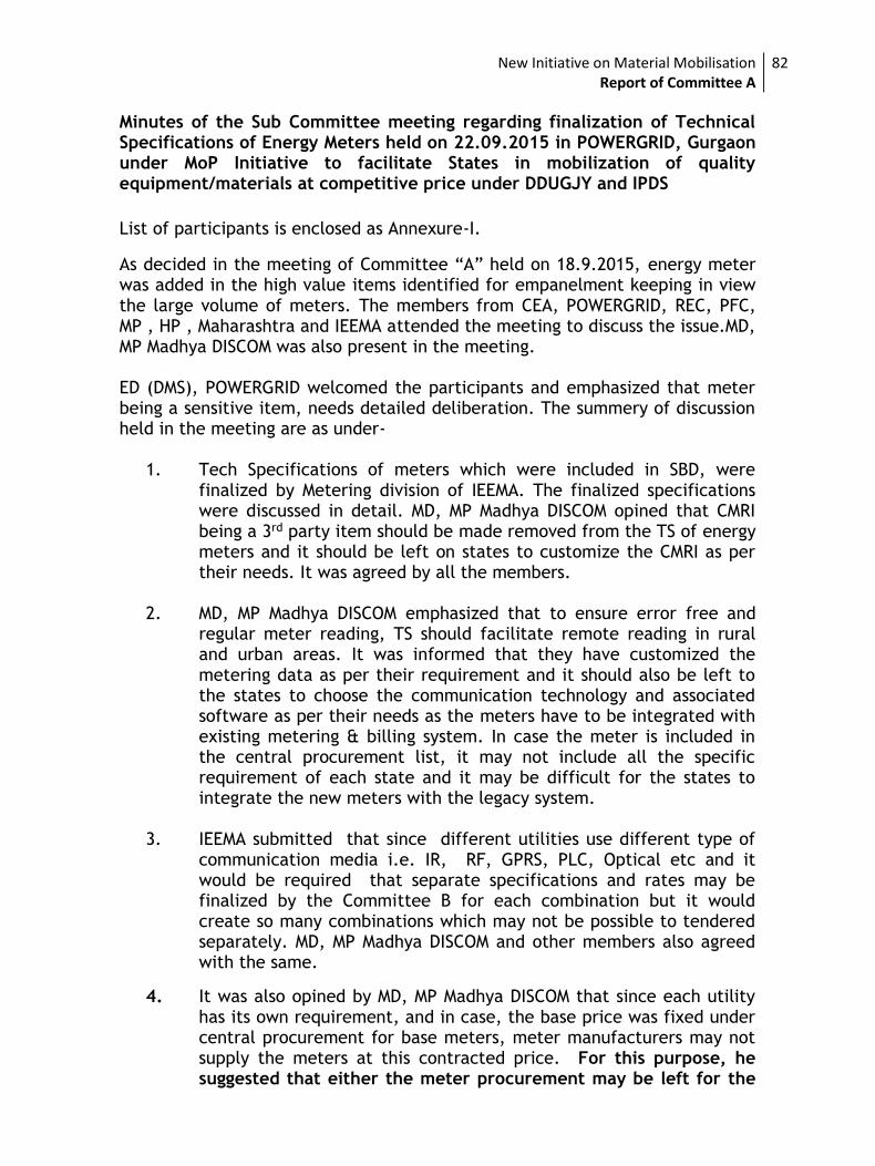
New Initiative on Material Mobilisation Report of Committee A
82
Minutes of the Sub Committee meeting regarding finalization of Technical Specifications of Energy Meters held on 22.09.2015 in POWERGRID, Gurgaon under MoP Initiative to facilitate States in mobilization of quality equipment/materials at competitive price under DDUGJY and IPDS
List of participants is enclosed as Annexure-I.
As decided in the meeting of Committee “A” held on 18.9.2015, energy meter was added in the high value items identified for empanelment keeping in view the large volume of meters. The members from CEA, POWERGRID, REC, PFC, MP , HP , Maharashtra and IEEMA attended the meeting to discuss the issue.MD, MP Madhya DISCOM was also present in the meeting. ED (DMS), POWERGRID welcomed the participants and emphasized that meter being a sensitive item, needs detailed deliberation. The summery of discussion held in the meeting are as under-
1. Tech Specifications of meters which were included in SBD, were finalized by Metering division of IEEMA. The finalized specifications were discussed in detail. MD, MP Madhya DISCOM opined that CMRI being a 3rd party item should be made removed from the TS of energy meters and it should be left on states to customize the CMRI as per their needs. It was agreed by all the members.
2. MD, MP Madhya DISCOM emphasized that to ensure error free and regular meter reading, TS should facilitate remote reading in rural and urban areas. It was informed that they have customized the metering data as per their requirement and it should also be left to the states to choose the communication technology and associated software as per their needs as the meters have to be integrated with existing metering & billing system. In case the meter is included in the central procurement list, it may not include all the specific requirement of each state and it may be difficult for the states to integrate the new meters with the legacy system.
3. IEEMA submitted that since different utilities use different type of communication media i.e. IR, RF, GPRS, PLC, Optical etc and it would be required that separate specifications and rates may be finalized by the Committee B for each combination but it would create so many combinations which may not be possible to tendered separately. MD, MP Madhya DISCOM and other members also agreed with the same.
4. It was also opined by MD, MP Madhya DISCOM that since each utility has its own requirement, and in case, the base price was fixed under central procurement for base meters, meter manufacturers may not supply the meters at this contracted price. For this purpose, he suggested that either the meter procurement may be left for the
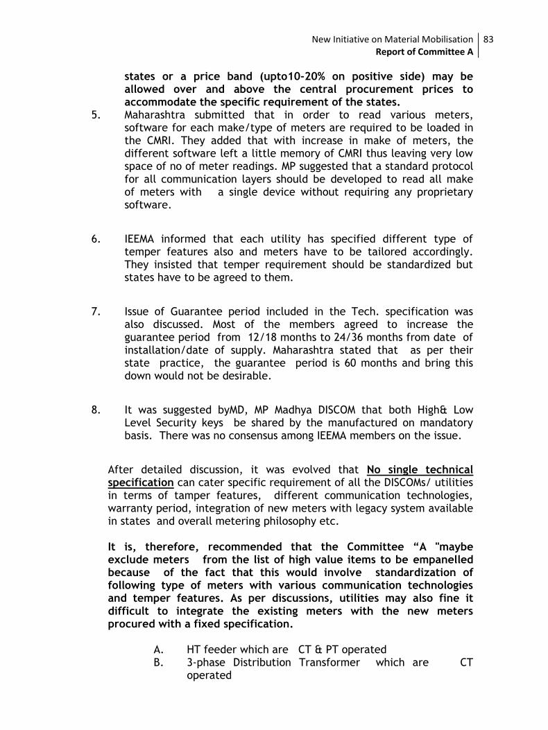
New Initiative on Material Mobilisation Report of Committee A
83
states or a price band (upto10-20% on positive side) may be allowed over and above the central procurement prices to accommodate the specific requirement of the states.
5. Maharashtra submitted that in order to read various meters, software for each make/type of meters are required to be loaded in the CMRI. They added that with increase in make of meters, the different software left a little memory of CMRI thus leaving very low space of no of meter readings. MP suggested that a standard protocol for all communication layers should be developed to read all make of meters with a single device without requiring any proprietary software.
6. IEEMA informed that each utility has specified different type of temper features also and meters have to be tailored accordingly. They insisted that temper requirement should be standardized but states have to be agreed to them.
7. Issue of Guarantee period included in the Tech. specification was also discussed. Most of the members agreed to increase the guarantee period from 12/18 months to 24/36 months from date of installation/date of supply. Maharashtra stated that as per their state practice, the guarantee period is 60 months and bring this down would not be desirable.
8. It was suggested byMD, MP Madhya DISCOM that both High& Low Level Security keys be shared by the manufactured on mandatory basis. There was no consensus among IEEMA members on the issue.
After detailed discussion, it was evolved that No single technical specification can cater specific requirement of all the DISCOMs/ utilities in terms of tamper features, different communication technologies, warranty period, integration of new meters with legacy system available in states and overall metering philosophy etc. It is, therefore, recommended that the Committee “A "maybe exclude meters from the list of high value items to be empanelled because of the fact that this would involve standardization of following type of meters with various communication technologies and temper features. As per discussions, utilities may also fine it difficult to integrate the existing meters with the new meters procured with a fixed specification.
A. HT feeder which are CT & PT operated B. 3-phase Distribution Transformer which are CT
operated
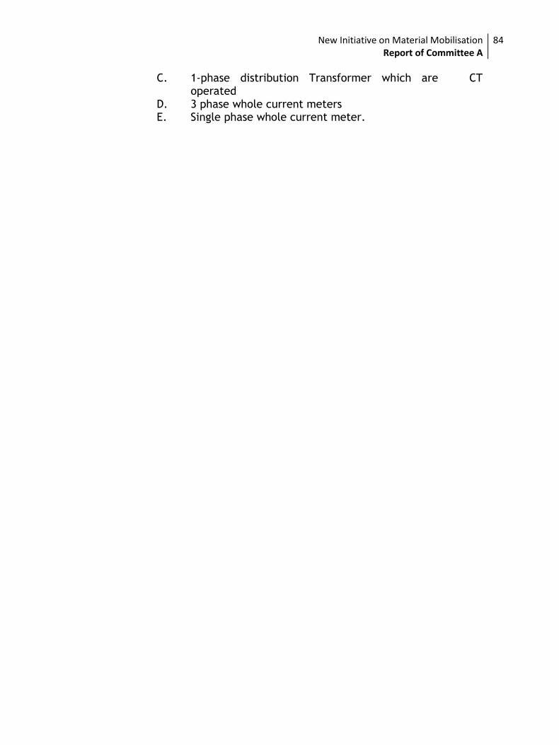
New Initiative on Material Mobilisation Report of Committee A
84
C. 1-phase distribution Transformer which are CT operated
D. 3 phase whole current meters E. Single phase whole current meter.
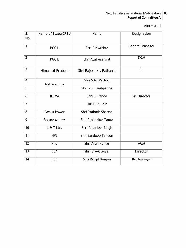
New Initiative on Material Mobilisation Report of Committee A
85
Annexure-I
S.
No.
Name of State/CPSU Name Designation
1 PGCIL Shri S K Mishra
General Manager
2 PGCIL Shri Atul Agarwal
DGM
3 Himachal Pradesh Shri Rajesh Kr. Pathania
SE
4 Maharashtra
Shri S.M. Rathod
5 Shri S.V. Deshpande
6 IEEMA Shri J. Pande Sr. Director
7 Shri C.P. Jain
8 Genus Power Shri Yathath Sharma
9 Secure Meters Shri Prabhakar Tanta
10 L & T Ltd. Shri Amarjeet Singh
11 HPL Shri Sandeep Tandon
12 PFC Shri Arun Kumar AGM
13 CEA Shri Vivek Goyal Director
14 REC Shri Ranjit Ranjan Dy. Manager
New Initiative on Material Mobilisation Report of Committee A
86
Annexure-V
Technical specifications
of Major
High Value Materials
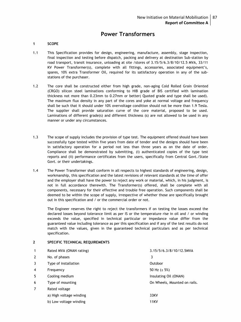
New Initiative on Material Mobilisation Report of Committee A
87
Power Transformers 1 SCOPE
1.1 This Specification provides for design, engineering, manufacture, assembly, stage inspection,
final inspection and testing before dispatch, packing and delivery at destination Sub-station by
road transport, transit insurance, unloading at site /stores of 3.15/5/6.3/8/10/12.5 MVA, 33/11
KV Power Transformer(s), complete with all fittings, accessories, associated equipment’s,
spares, 10% extra Transformer Oil, required for its satisfactory operation in any of the sub-
stations of the purchaser.
1.2 The core shall be constructed either from high grade, non-aging Cold Rolled Grain Oriented
(CRGO) silicon steel laminations conforming to HIB grade of BIS certified with lamination
thickness not more than 0.23mm to 0.27mm or better( Quoted grade and type shall be used).
The maximum flux density in any part of the cores and yoke at normal voltage and frequency
shall be such that it should under 10% overvoltage condition should not be more than 1.9 Tesla.
The supplier shall provide saturation curve of the core material, proposed to be used.
Laminations of different grade(s) and different thickness (s) are not allowed to be used in any
manner or under any circumstances.
1.3 The scope of supply includes the provision of type test. The equipment offered should have been
successfully type tested within five years from date of tender and the designs should have been
in satisfactory operation for a period not less than three years as on the date of order.
Compliance shall be demonstrated by submitting, (i) authenticated copies of the type test
reports and (ii) performance certificates from the users, specifically from Central Govt./State
Govt. or their undertakings.
1.4 The Power Transformer shall conform in all respects to highest standards of engineering, design,
workmanship, this specification and the latest revisions of relevant standards at the time of offer
and the employer shall have the power to reject any work or material, which, in his judgment, is
not in full accordance therewith. The Transformer(s) offered, shall be complete with all
components, necessary for their effective and trouble free operation. Such components shall be
deemed to be within the scope of supply, irrespective of whether those are specifically brought
out in this specification and / or the commercial order or not.
The Engineer reserves the right to reject the transformers if on testing the losses exceed the
declared losses beyond tolerance limit as per IS or the temperature rise in oil and / or winding
exceeds the value, specified in technical particular or impedance value differ from the
guaranteed value including tolerance as per this specification and if any of the test results do not
match with the values, given in the guaranteed technical particulars and as per technical
specification.
2 SPECIFIC TECHNICAL REQUIREMENTS 1 Rated MVA (ONAN rating) 3.15/5/6.3/8/10/12.5MVA
2 No. of phases 3
3 Type of installation Outdoor
4 Frequency 50 Hz (± 5%)
5 Cooling medium Insulating Oil (ONAN)
6 Type of mounting On Wheels, Mounted on rails.
7 Rated voltage
a) High voltage winding 33KV
b) Low voltage winding 11KV
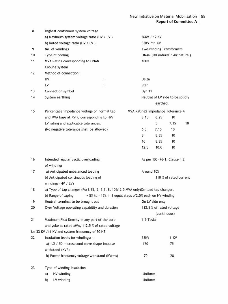
New Initiative on Material Mobilisation Report of Committee A
88
8 Highest continuous system voltage
a) Maximum system voltage ratio (HV / LV ) 36KV / 12 KV
b) Rated voltage ratio (HV / LV ) 33KV /11 KV
9 No. of windings Two winding Transformers
10 Type of cooling ONAN (Oil natural / Air natural)
11 MVA Rating corresponding to ONAN 100%
Cooling system
12 Method of connection:
HV : Delta
LV : Star
13 Connection symbol Dyn 11
14 System earthing Neutral of LV side to be solidly
earthed.
15 Percentage impedance voltage on normal tap MVA Rating% Impedance Tolerance %
and MVA base at 75o C corresponding to HV/ 3.15 6.25 10
LV rating and applicable tolerances: 5 7.15 10
(No negative tolerance shall be allowed) 6.3 7.15 10
8 8.35 10
10 8.35 10
12.5 10.0 10
16 Intended regular cyclic overloading As per IEC –76-1, Clause 4.2
of windings
17 a) Anticipated unbalanced loading Around 10%
b) Anticipated continuous loading of 110 % of rated current
windings (HV / LV)
18 a) Type of tap changer (For3.15, 5, 6.3, 8, 10&12.5 MVA only)On-load tap changer.
b) Range of taping + 5% to – 15% in 8 equal steps of2.5% each on HV winding
19 Neutral terminal to be brought out On LV side only
20 Over Voltage operating capability and duration 112.5 % of rated voltage
(continuous)
21 Maximum Flux Density in any part of the core 1.9 Tesla
and yoke at rated MVA, 112.5 % of rated voltage
i.e 33 KV /11 KV and system frequency of 50 HZ
22 Insulation levels for windings: - 33KV 11KV
a) 1.2 / 50 microsecond wave shape Impulse 170 75
withstand (KVP)
b) Power frequency voltage withstand (KVrms) 70 28
23 Type of winding insulation
a) HV winding Uniform
b) LV winding Uniform
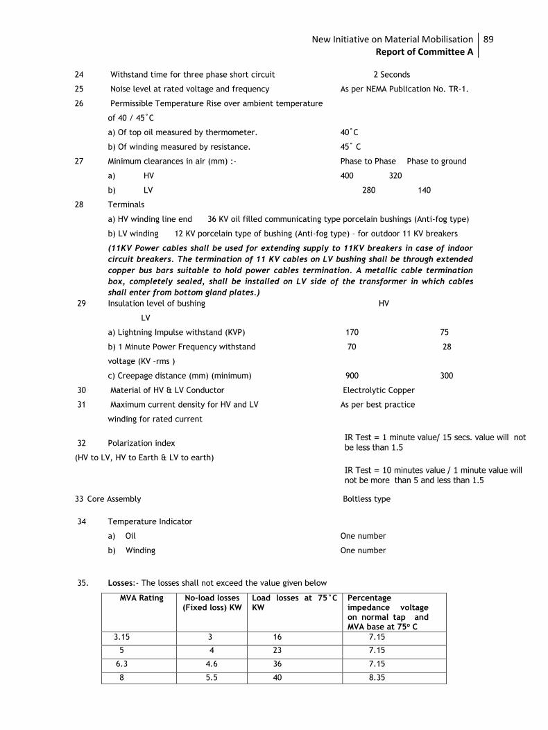
New Initiative on Material Mobilisation Report of Committee A
89
24 Withstand time for three phase short circuit 2 Seconds
25 Noise level at rated voltage and frequency As per NEMA Publication No. TR-1.
26 Permissible Temperature Rise over ambient temperature
of 40 / 45˚C
a) Of top oil measured by thermometer. 40˚C
b) Of winding measured by resistance. 45˚ C
27 Minimum clearances in air (mm) :- Phase to Phase Phase to ground
a) HV 400 320
b) LV 280 140
28 Terminals
a) HV winding line end 36 KV oil filled communicating type porcelain bushings (Anti-fog type)
b) LV winding 12 KV porcelain type of bushing (Anti-fog type) – for outdoor 11 KV breakers
(11KV Power cables shall be used for extending supply to 11KV breakers in case of indoor
circuit breakers. The termination of 11 KV cables on LV bushing shall be through extended
copper bus bars suitable to hold power cables termination. A metallic cable termination
box, completely sealed, shall be installed on LV side of the transformer in which cables
shall enter from bottom gland plates.)
29 Insulation level of bushing HV
LV
a) Lightning Impulse withstand (KVP) 170 75
b) 1 Minute Power Frequency withstand 70 28
voltage (KV –rms )
c) Creepage distance (mm) (minimum) 900 300
30 Material of HV & LV Conductor Electrolytic Copper
31 Maximum current density for HV and LV As per best practice
winding for rated current
32 Polarization index
(HV to LV, HV to Earth & LV to earth)
33 Core Assembly Boltless type
34 Temperature Indicator
a) Oil One number
b) Winding One number
35. Losses:- The losses shall not exceed the value given below
MVA Rating No-load losses (Fixed loss) KW
Load losses at 75°C KW
Percentage impedance voltage on normal tap and MVA base at 75o C
3.15 3 16 7.15
5 4 23 7.15
6.3 4.6 36 7.15
8 5.5 40 8.35
IR Test = 1 minute value/ 15 secs. value will not be less than 1.5
IR Test = 10 minutes value / 1 minute value will not be more than 5 and less than 1.5
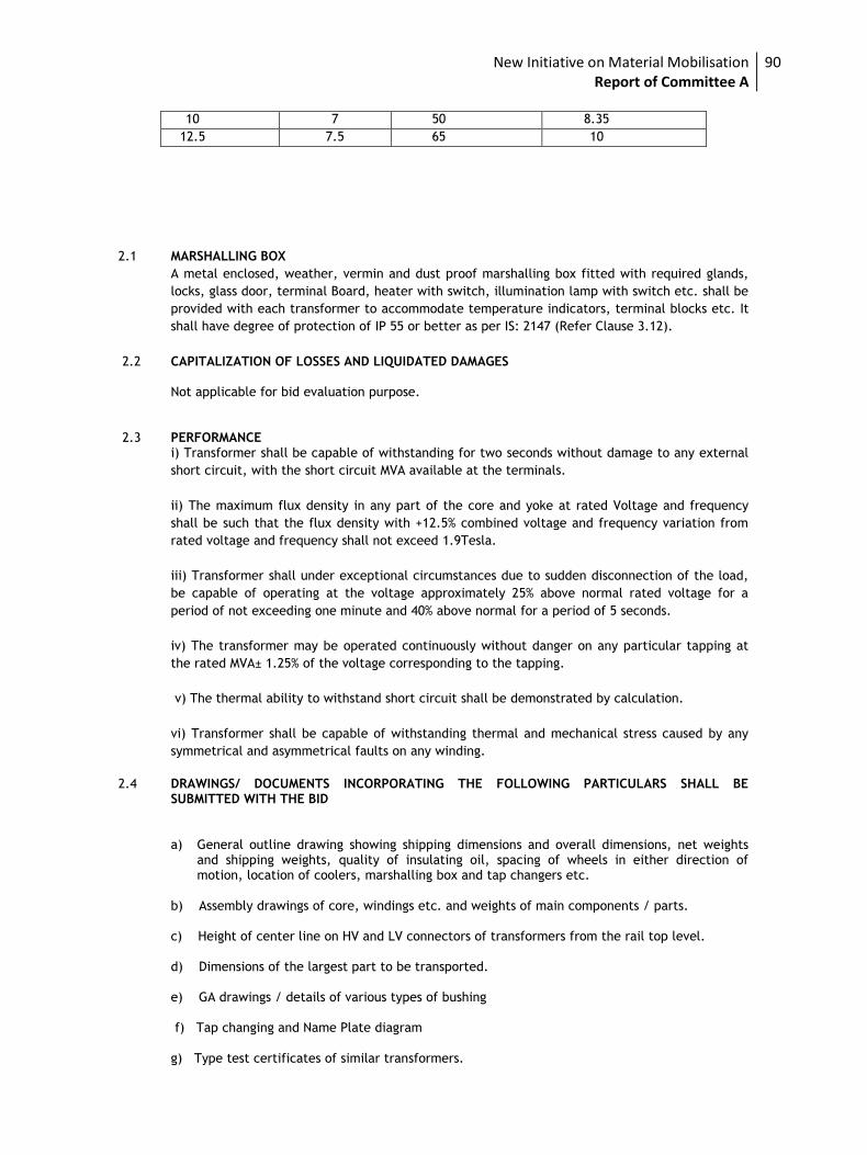
New Initiative on Material Mobilisation Report of Committee A
90
2.1 MARSHALLING BOX
A metal enclosed, weather, vermin and dust proof marshalling box fitted with required glands,
locks, glass door, terminal Board, heater with switch, illumination lamp with switch etc. shall be
provided with each transformer to accommodate temperature indicators, terminal blocks etc. It
shall have degree of protection of IP 55 or better as per IS: 2147 (Refer Clause 3.12).
2.2 CAPITALIZATION OF LOSSES AND LIQUIDATED DAMAGES Not applicable for bid evaluation purpose. 2.3 PERFORMANCE i) Transformer shall be capable of withstanding for two seconds without damage to any external
short circuit, with the short circuit MVA available at the terminals.
ii) The maximum flux density in any part of the core and yoke at rated Voltage and frequency
shall be such that the flux density with +12.5% combined voltage and frequency variation from
rated voltage and frequency shall not exceed 1.9Tesla.
iii) Transformer shall under exceptional circumstances due to sudden disconnection of the load,
be capable of operating at the voltage approximately 25% above normal rated voltage for a
period of not exceeding one minute and 40% above normal for a period of 5 seconds.
iv) The transformer may be operated continuously without danger on any particular tapping at
the rated MVA± 1.25% of the voltage corresponding to the tapping.
v) The thermal ability to withstand short circuit shall be demonstrated by calculation.
vi) Transformer shall be capable of withstanding thermal and mechanical stress caused by any
symmetrical and asymmetrical faults on any winding.
2.4 DRAWINGS/ DOCUMENTS INCORPORATING THE FOLLOWING PARTICULARS SHALL BE
SUBMITTED WITH THE BID
a) General outline drawing showing shipping dimensions and overall dimensions, net weights and shipping weights, quality of insulating oil, spacing of wheels in either direction of motion, location of coolers, marshalling box and tap changers etc.
b) Assembly drawings of core, windings etc. and weights of main components / parts. c) Height of center line on HV and LV connectors of transformers from the rail top level. d) Dimensions of the largest part to be transported. e) GA drawings / details of various types of bushing f) Tap changing and Name Plate diagram g) Type test certificates of similar transformers.
10 7 50 8.35
12.5 7.5 65 10
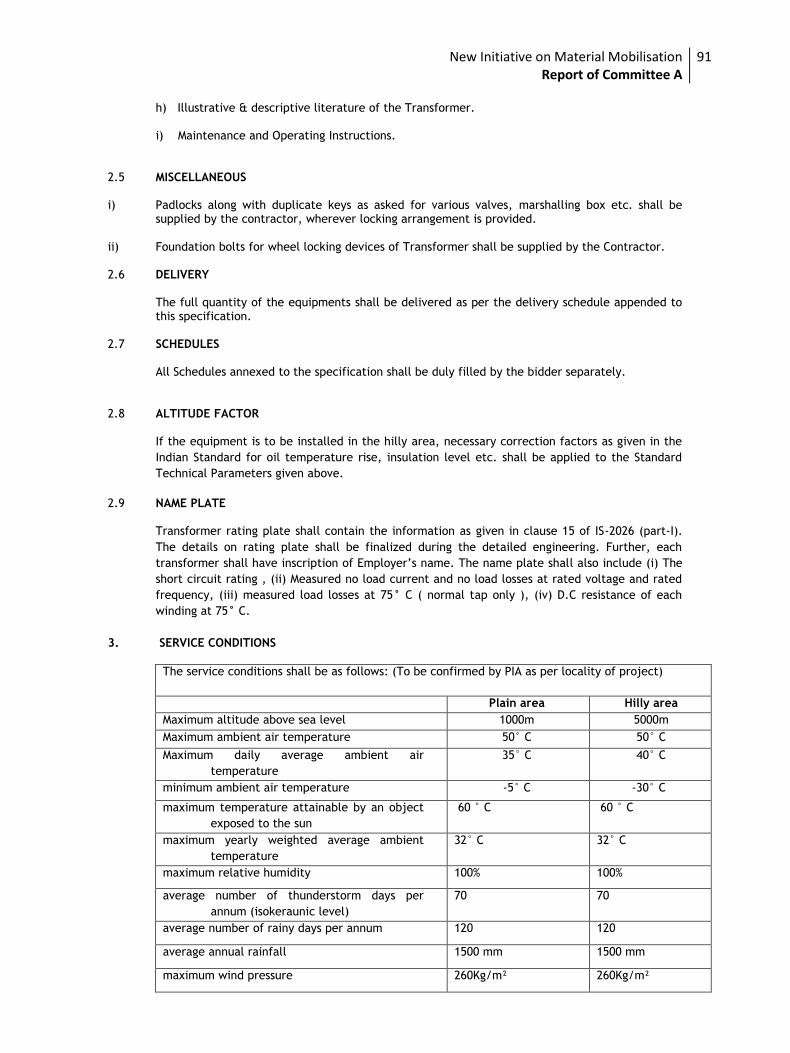
New Initiative on Material Mobilisation Report of Committee A
91
h) Illustrative & descriptive literature of the Transformer. i) Maintenance and Operating Instructions.
2.5 MISCELLANEOUS i) Padlocks along with duplicate keys as asked for various valves, marshalling box etc. shall be
supplied by the contractor, wherever locking arrangement is provided. ii) Foundation bolts for wheel locking devices of Transformer shall be supplied by the Contractor. 2.6 DELIVERY The full quantity of the equipments shall be delivered as per the delivery schedule appended to
this specification. 2.7 SCHEDULES All Schedules annexed to the specification shall be duly filled by the bidder separately. 2.8 ALTITUDE FACTOR If the equipment is to be installed in the hilly area, necessary correction factors as given in the
Indian Standard for oil temperature rise, insulation level etc. shall be applied to the Standard
Technical Parameters given above.
2.9 NAME PLATE Transformer rating plate shall contain the information as given in clause 15 of IS-2026 (part-I).
The details on rating plate shall be finalized during the detailed engineering. Further, each
transformer shall have inscription of Employer’s name. The name plate shall also include (i) The
short circuit rating , (ii) Measured no load current and no load losses at rated voltage and rated
frequency, (iii) measured load losses at 75° C ( normal tap only ), (iv) D.C resistance of each
winding at 75° C.
3. SERVICE CONDITIONS
The service conditions shall be as follows: (To be confirmed by PIA as per locality of project)
Plain area Hilly area
Maximum altitude above sea level 1000m 5000m
Maximum ambient air temperature 50° C 50° C
Maximum daily average ambient air
temperature
35° C 40° C
minimum ambient air temperature -5° C -30° C
maximum temperature attainable by an object
exposed to the sun
60 ° C 60 ° C
maximum yearly weighted average ambient
temperature
32° C 32° C
maximum relative humidity 100% 100%
average number of thunderstorm days per
annum (isokeraunic level)
70 70
average number of rainy days per annum 120 120
average annual rainfall 1500 mm 1500 mm
maximum wind pressure 260Kg/m² 260Kg/m²
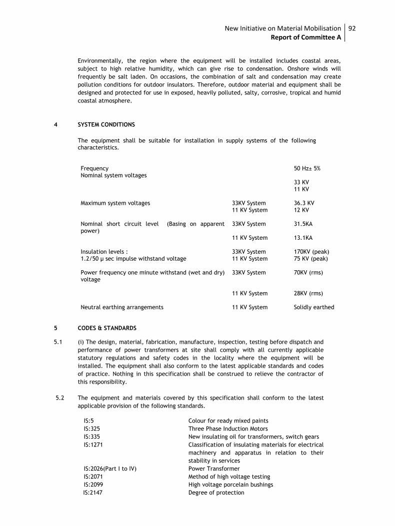
New Initiative on Material Mobilisation Report of Committee A
92
Environmentally, the region where the equipment will be installed includes coastal areas,
subject to high relative humidity, which can give rise to condensation. Onshore winds will
frequently be salt laden. On occasions, the combination of salt and condensation may create
pollution conditions for outdoor insulators. Therefore, outdoor material and equipment shall be
designed and protected for use in exposed, heavily polluted, salty, corrosive, tropical and humid
coastal atmosphere.
4 SYSTEM CONDITIONS
The equipment shall be suitable for installation in supply systems of the following characteristics.
Frequency 50 Hz± 5% Nominal system voltages 33 KV 11 KV Maximum system voltages 33KV System 36.3 KV 11 KV System 12 KV Nominal short circuit level (Basing on apparent power)
33KV System 31.5KA
11 KV System 13.1KA Insulation levels : 33KV System 170KV (peak) 1.2/50 μ sec impulse withstand voltage 11 KV System 75 KV (peak) Power frequency one minute withstand (wet and dry) voltage
33KV System 70KV (rms)
11 KV System 28KV (rms) Neutral earthing arrangements 11 KV System Solidly earthed
5 CODES & STANDARDS 5.1 (i) The design, material, fabrication, manufacture, inspection, testing before dispatch and
performance of power transformers at site shall comply with all currently applicable
statutory regulations and safety codes in the locality where the equipment will be
installed. The equipment shall also conform to the latest applicable standards and codes
of practice. Nothing in this specification shall be construed to relieve the contractor of
this responsibility.
5.2 The equipment and materials covered by this specification shall conform to the latest
applicable provision of the following standards.
IS:5 Colour for ready mixed paints
IS:325 Three Phase Induction Motors
IS:335 New insulating oil for transformers, switch gears
IS:1271 Classification of insulating materials for electrical
machinery and apparatus in relation to their
stability in services
IS:2026(Part I to IV) Power Transformer
IS:2071 Method of high voltage testing
IS:2099 High voltage porcelain bushings
IS:2147 Degree of protection
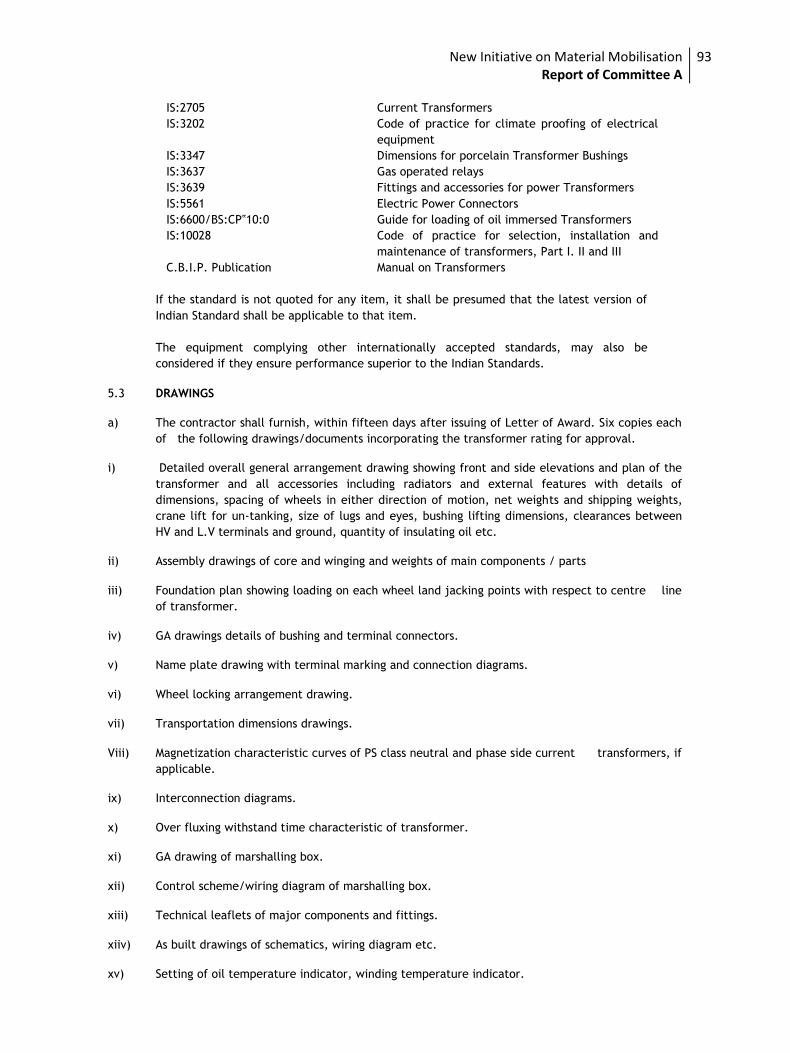
New Initiative on Material Mobilisation Report of Committee A
93
IS:2705 Current Transformers
IS:3202 Code of practice for climate proofing of electrical
equipment
IS:3347 Dimensions for porcelain Transformer Bushings
IS:3637 Gas operated relays
IS:3639 Fittings and accessories for power Transformers
IS:5561 Electric Power Connectors
IS:6600/BS:CP‟10:0 Guide for loading of oil immersed Transformers
IS:10028 Code of practice for selection, installation and
maintenance of transformers, Part I. II and III
C.B.I.P. Publication Manual on Transformers
If the standard is not quoted for any item, it shall be presumed that the latest version of
Indian Standard shall be applicable to that item.
The equipment complying other internationally accepted standards, may also be
considered if they ensure performance superior to the Indian Standards.
5.3 DRAWINGS
a) The contractor shall furnish, within fifteen days after issuing of Letter of Award. Six copies each
of the following drawings/documents incorporating the transformer rating for approval.
i) Detailed overall general arrangement drawing showing front and side elevations and plan of the
transformer and all accessories including radiators and external features with details of
dimensions, spacing of wheels in either direction of motion, net weights and shipping weights,
crane lift for un-tanking, size of lugs and eyes, bushing lifting dimensions, clearances between
HV and L.V terminals and ground, quantity of insulating oil etc.
ii) Assembly drawings of core and winging and weights of main components / parts
iii) Foundation plan showing loading on each wheel land jacking points with respect to centre line
of transformer.
iv) GA drawings details of bushing and terminal connectors.
v) Name plate drawing with terminal marking and connection diagrams.
vi) Wheel locking arrangement drawing.
vii) Transportation dimensions drawings.
Viii) Magnetization characteristic curves of PS class neutral and phase side current transformers, if
applicable.
ix) Interconnection diagrams.
x) Over fluxing withstand time characteristic of transformer.
xi) GA drawing of marshalling box.
xii) Control scheme/wiring diagram of marshalling box.
xiii) Technical leaflets of major components and fittings.
xiiv) As built drawings of schematics, wiring diagram etc.
xv) Setting of oil temperature indicator, winding temperature indicator.
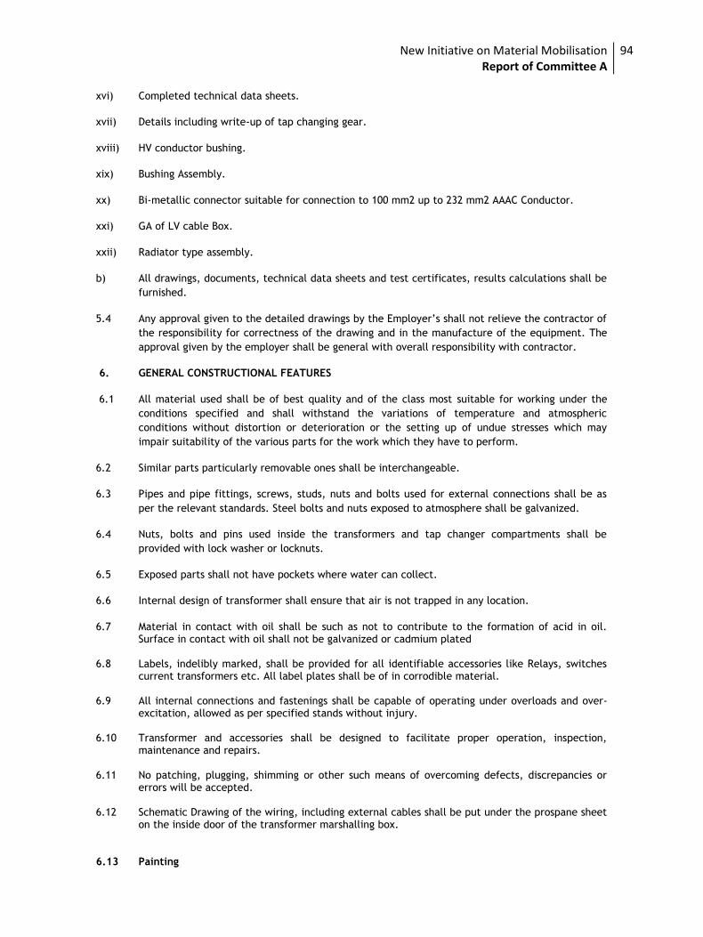
New Initiative on Material Mobilisation Report of Committee A
94
xvi) Completed technical data sheets.
xvii) Details including write-up of tap changing gear.
xviii) HV conductor bushing.
xix) Bushing Assembly.
xx) Bi-metallic connector suitable for connection to 100 mm2 up to 232 mm2 AAAC Conductor.
xxi) GA of LV cable Box.
xxii) Radiator type assembly.
b) All drawings, documents, technical data sheets and test certificates, results calculations shall be
furnished.
5.4 Any approval given to the detailed drawings by the Employer’s shall not relieve the contractor of
the responsibility for correctness of the drawing and in the manufacture of the equipment. The
approval given by the employer shall be general with overall responsibility with contractor.
6. GENERAL CONSTRUCTIONAL FEATURES
6.1 All material used shall be of best quality and of the class most suitable for working under the
conditions specified and shall withstand the variations of temperature and atmospheric
conditions without distortion or deterioration or the setting up of undue stresses which may
impair suitability of the various parts for the work which they have to perform.
6.2 Similar parts particularly removable ones shall be interchangeable.
6.3 Pipes and pipe fittings, screws, studs, nuts and bolts used for external connections shall be as
per the relevant standards. Steel bolts and nuts exposed to atmosphere shall be galvanized.
6.4 Nuts, bolts and pins used inside the transformers and tap changer compartments shall be
provided with lock washer or locknuts.
6.5 Exposed parts shall not have pockets where water can collect.
6.6 Internal design of transformer shall ensure that air is not trapped in any location.
6.7 Material in contact with oil shall be such as not to contribute to the formation of acid in oil. Surface in contact with oil shall not be galvanized or cadmium plated
6.8 Labels, indelibly marked, shall be provided for all identifiable accessories like Relays, switches
current transformers etc. All label plates shall be of in corrodible material. 6.9 All internal connections and fastenings shall be capable of operating under overloads and over-
excitation, allowed as per specified stands without injury. 6.10 Transformer and accessories shall be designed to facilitate proper operation, inspection,
maintenance and repairs. 6.11 No patching, plugging, shimming or other such means of overcoming defects, discrepancies or
errors will be accepted. 6.12 Schematic Drawing of the wiring, including external cables shall be put under the prospane sheet
on the inside door of the transformer marshalling box. 6.13 Painting
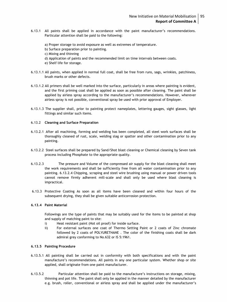
New Initiative on Material Mobilisation Report of Committee A
95
6.13.1 All paints shall be applied in accordance with the paint manufacturer’s recommendations.
Particular attention shall be paid to the following:
a) Proper storage to avoid exposure as well as extremes of temperature.
b) Surface preparation prior to painting.
c) Mixing and thinning
d) Application of paints and the recommended limit on time intervals between coats.
e) Shelf life for storage.
6.13.1.1 All paints, when applied in normal full coat, shall be free from runs, sags, wrinkles, patchiness,
brush marks or other defects.
6.13.1.2 All primers shall be well marked into the surface, particularly in areas where painting is evident,
and the first priming coat shall be applied as soon as possible after cleaning. The paint shall be
applied by airless spray according to the manufacturer’s recommendations. However, wherever
airless spray is not possible, conventional spray be used with prior approval of Employer.
6.13.1.3 The supplier shall, prior to painting protect nameplates, lettering gauges, sight glasses, light
fittings and similar such items.
6.13.2 Cleaning and Surface Preparation
6.13.2.1 After all machining, forming and welding has been completed, all steel work surfaces shall be
thoroughly cleaned of rust, scale, welding slag or spatter and other contamination prior to any
painting.
6.13.2.2 Steel surfaces shall be prepared by Sand/Shot blast cleaning or Chemical cleaning by Seven tank
process including Phosphate to the appropriate quality.
6.13.2.3 The pressure and Volume of the compressed air supply for the blast cleaning shall meet
the work requirements and shall be sufficiently free from all water contamination prior to any
painting. 6.13.2.4 Chipping, scraping and steel wire brushing using manual or power driven tools
cannot remove firmly adherent mill-scale and shall only be used where blast cleaning is
impractical.
6.13.3 Protective Coating As soon as all items have been cleaned and within four hours of the
subsequent drying, they shall be given suitable anticorrosion protection.
6.13.4 Paint Material
Followings are the type of paints that may be suitably used for the items to be painted at shop
and supply of matching paint to site:
i) Heat resistant paint (Hot oil proof) for inside surface.
ii) For external surfaces one coat of Thermo Setting Paint or 2 coats of Zinc chromate
followed by 2 coats of POLYURETHANE . The color of the finishing coats shall be dark
admiral grey conforming to No.632 or IS 5:1961.
6.13.5 Painting Procedure
6.13.5.1 All painting shall be carried out in conformity with both specifications and with the paint
manufacture’s recommendations. All paints in any one particular system. Whether shop or site
applied, shall originate from one paint manufacturer.
6.13.5.2 Particular attention shall be paid to the manufacture’s instructions on storage, mixing,
thinning and pot life. The paint shall only be applied in the manner detailed by the manufacturer
e.g. brush, roller, conventional or airless spray and shall be applied under the manufacturer’s
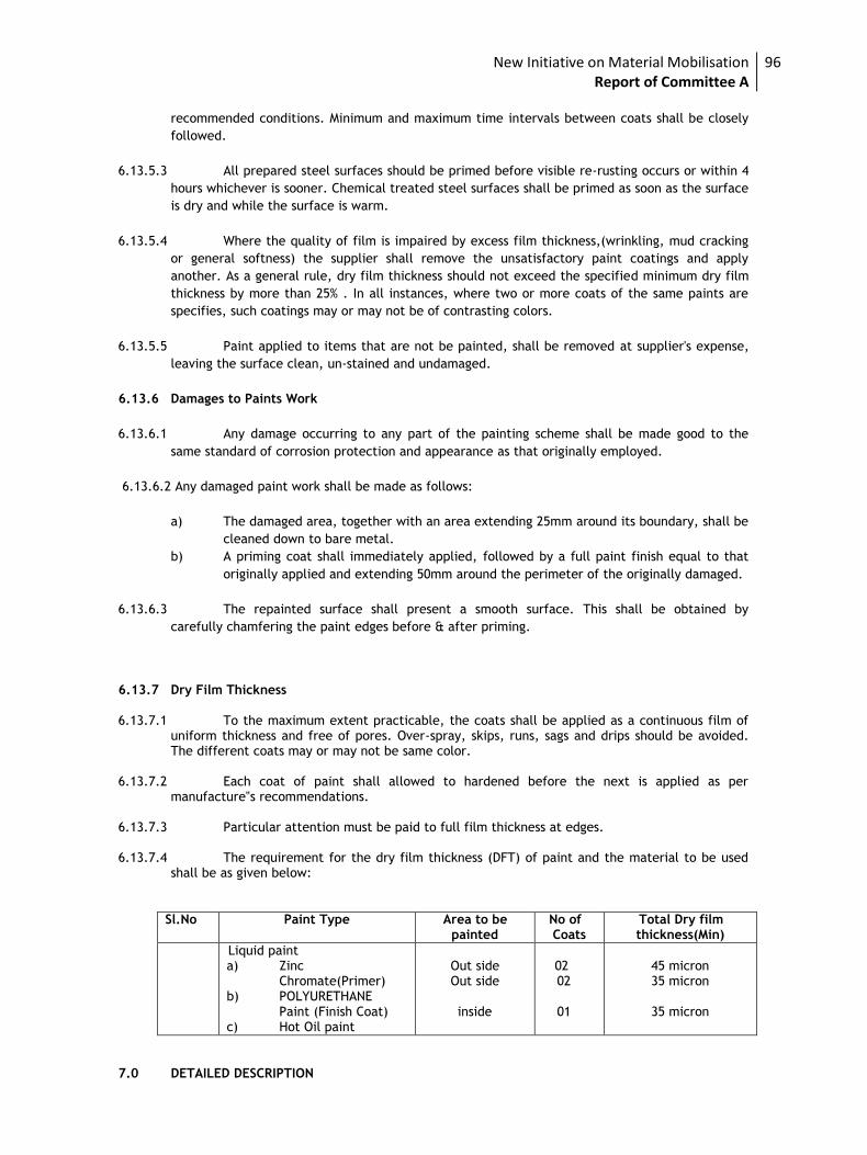
New Initiative on Material Mobilisation Report of Committee A
96
recommended conditions. Minimum and maximum time intervals between coats shall be closely
followed.
6.13.5.3 All prepared steel surfaces should be primed before visible re-rusting occurs or within 4
hours whichever is sooner. Chemical treated steel surfaces shall be primed as soon as the surface
is dry and while the surface is warm.
6.13.5.4 Where the quality of film is impaired by excess film thickness,(wrinkling, mud cracking
or general softness) the supplier shall remove the unsatisfactory paint coatings and apply
another. As a general rule, dry film thickness should not exceed the specified minimum dry film
thickness by more than 25% . In all instances, where two or more coats of the same paints are
specifies, such coatings may or may not be of contrasting colors.
6.13.5.5 Paint applied to items that are not be painted, shall be removed at supplier's expense,
leaving the surface clean, un-stained and undamaged.
6.13.6 Damages to Paints Work
6.13.6.1 Any damage occurring to any part of the painting scheme shall be made good to the
same standard of corrosion protection and appearance as that originally employed.
6.13.6.2 Any damaged paint work shall be made as follows:
a) The damaged area, together with an area extending 25mm around its boundary, shall be
cleaned down to bare metal.
b) A priming coat shall immediately applied, followed by a full paint finish equal to that
originally applied and extending 50mm around the perimeter of the originally damaged.
6.13.6.3 The repainted surface shall present a smooth surface. This shall be obtained by
carefully chamfering the paint edges before & after priming.
6.13.7 Dry Film Thickness 6.13.7.1 To the maximum extent practicable, the coats shall be applied as a continuous film of
uniform thickness and free of pores. Over-spray, skips, runs, sags and drips should be avoided. The different coats may or may not be same color.
6.13.7.2 Each coat of paint shall allowed to hardened before the next is applied as per
manufacture‟s recommendations. 6.13.7.3 Particular attention must be paid to full film thickness at edges. 6.13.7.4 The requirement for the dry film thickness (DFT) of paint and the material to be used
shall be as given below:
Sl.No Paint Type Area to be painted
No of Coats
Total Dry film thickness(Min)
1 Liquid paint a) Zinc
Chromate(Primer) b) POLYURETHANE
Paint (Finish Coat) c) Hot Oil paint
Out side Out side
inside
02 02
01
45 micron 35 micron
35 micron
7.0 DETAILED DESCRIPTION
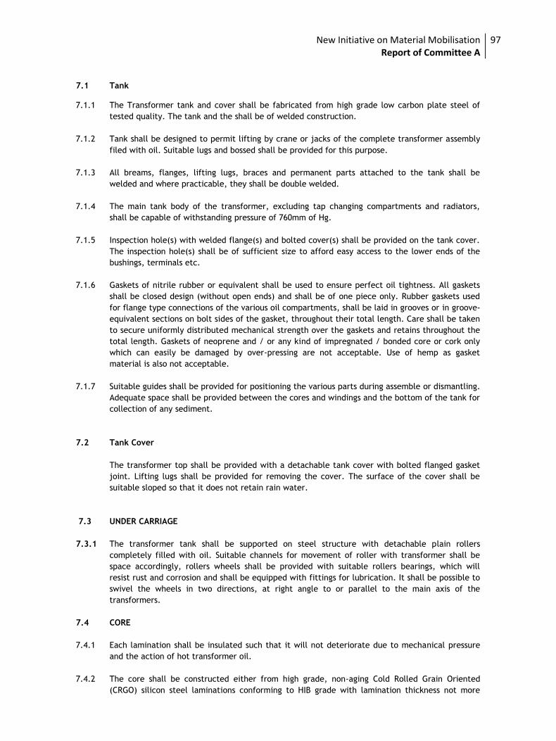
New Initiative on Material Mobilisation Report of Committee A
97
7.1 Tank 7.1.1 The Transformer tank and cover shall be fabricated from high grade low carbon plate steel of
tested quality. The tank and the shall be of welded construction.
7.1.2 Tank shall be designed to permit lifting by crane or jacks of the complete transformer assembly
filed with oil. Suitable lugs and bossed shall be provided for this purpose.
7.1.3 All breams, flanges, lifting lugs, braces and permanent parts attached to the tank shall be
welded and where practicable, they shall be double welded.
7.1.4 The main tank body of the transformer, excluding tap changing compartments and radiators,
shall be capable of withstanding pressure of 760mm of Hg.
7.1.5 Inspection hole(s) with welded flange(s) and bolted cover(s) shall be provided on the tank cover.
The inspection hole(s) shall be of sufficient size to afford easy access to the lower ends of the
bushings, terminals etc.
7.1.6 Gaskets of nitrile rubber or equivalent shall be used to ensure perfect oil tightness. All gaskets
shall be closed design (without open ends) and shall be of one piece only. Rubber gaskets used
for flange type connections of the various oil compartments, shall be laid in grooves or in groove-
equivalent sections on bolt sides of the gasket, throughout their total length. Care shall be taken
to secure uniformly distributed mechanical strength over the gaskets and retains throughout the
total length. Gaskets of neoprene and / or any kind of impregnated / bonded core or cork only
which can easily be damaged by over-pressing are not acceptable. Use of hemp as gasket
material is also not acceptable.
7.1.7 Suitable guides shall be provided for positioning the various parts during assemble or dismantling.
Adequate space shall be provided between the cores and windings and the bottom of the tank for
collection of any sediment.
7.2 Tank Cover
The transformer top shall be provided with a detachable tank cover with bolted flanged gasket
joint. Lifting lugs shall be provided for removing the cover. The surface of the cover shall be
suitable sloped so that it does not retain rain water.
7.3 UNDER CARRIAGE
7.3.1 The transformer tank shall be supported on steel structure with detachable plain rollers
completely filled with oil. Suitable channels for movement of roller with transformer shall be
space accordingly, rollers wheels shall be provided with suitable rollers bearings, which will
resist rust and corrosion and shall be equipped with fittings for lubrication. It shall be possible to
swivel the wheels in two directions, at right angle to or parallel to the main axis of the
transformers.
7.4 CORE
7.4.1 Each lamination shall be insulated such that it will not deteriorate due to mechanical pressure
and the action of hot transformer oil.
7.4.2 The core shall be constructed either from high grade, non-aging Cold Rolled Grain Oriented
(CRGO) silicon steel laminations conforming to HIB grade with lamination thickness not more
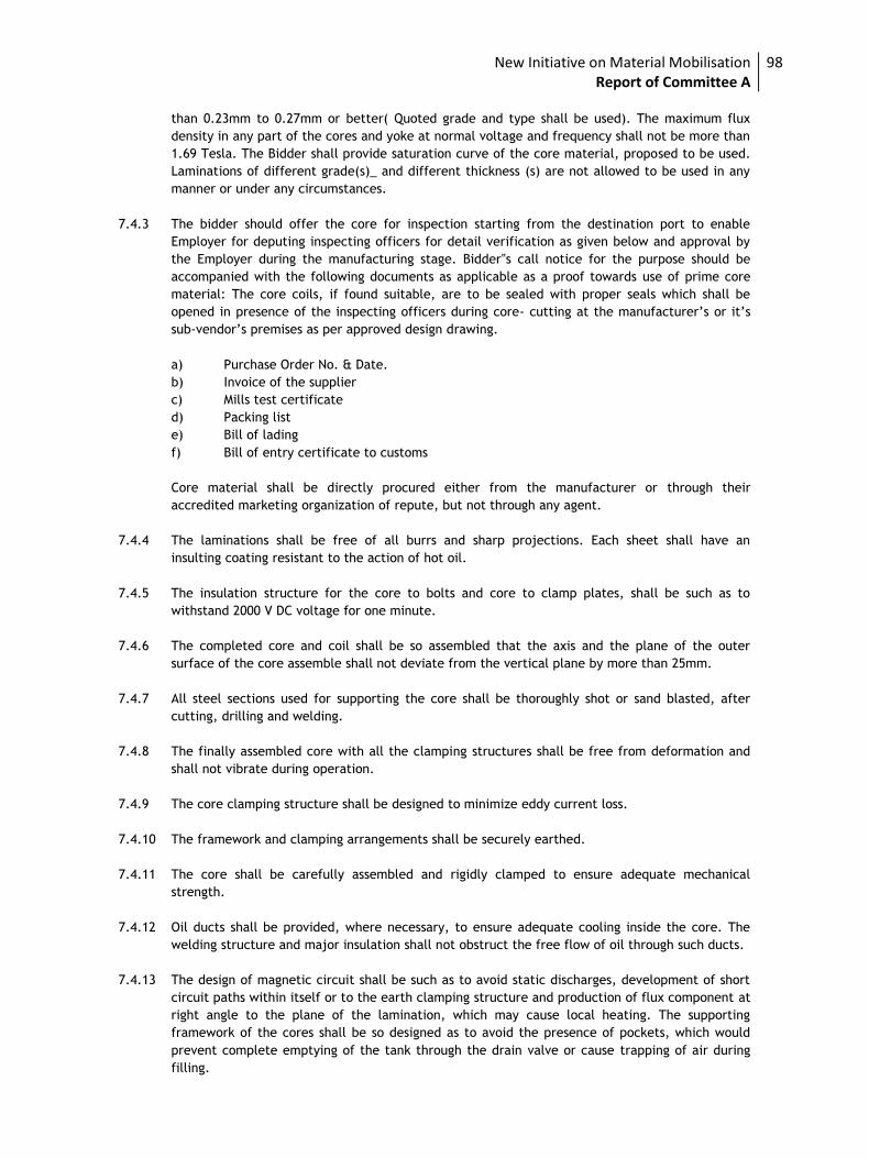
New Initiative on Material Mobilisation Report of Committee A
98
than 0.23mm to 0.27mm or better( Quoted grade and type shall be used). The maximum flux
density in any part of the cores and yoke at normal voltage and frequency shall not be more than
1.69 Tesla. The Bidder shall provide saturation curve of the core material, proposed to be used.
Laminations of different grade(s)_ and different thickness (s) are not allowed to be used in any
manner or under any circumstances.
7.4.3 The bidder should offer the core for inspection starting from the destination port to enable
Employer for deputing inspecting officers for detail verification as given below and approval by
the Employer during the manufacturing stage. Bidder‟s call notice for the purpose should be
accompanied with the following documents as applicable as a proof towards use of prime core
material: The core coils, if found suitable, are to be sealed with proper seals which shall be
opened in presence of the inspecting officers during core- cutting at the manufacturer’s or it’s
sub-vendor’s premises as per approved design drawing.
a) Purchase Order No. & Date.
b) Invoice of the supplier
c) Mills test certificate
d) Packing list
e) Bill of lading
f) Bill of entry certificate to customs
Core material shall be directly procured either from the manufacturer or through their
accredited marketing organization of repute, but not through any agent.
7.4.4 The laminations shall be free of all burrs and sharp projections. Each sheet shall have an
insulting coating resistant to the action of hot oil.
7.4.5 The insulation structure for the core to bolts and core to clamp plates, shall be such as to
withstand 2000 V DC voltage for one minute.
7.4.6 The completed core and coil shall be so assembled that the axis and the plane of the outer
surface of the core assemble shall not deviate from the vertical plane by more than 25mm.
7.4.7 All steel sections used for supporting the core shall be thoroughly shot or sand blasted, after
cutting, drilling and welding.
7.4.8 The finally assembled core with all the clamping structures shall be free from deformation and
shall not vibrate during operation.
7.4.9 The core clamping structure shall be designed to minimize eddy current loss.
7.4.10 The framework and clamping arrangements shall be securely earthed.
7.4.11 The core shall be carefully assembled and rigidly clamped to ensure adequate mechanical
strength.
7.4.12 Oil ducts shall be provided, where necessary, to ensure adequate cooling inside the core. The
welding structure and major insulation shall not obstruct the free flow of oil through such ducts.
7.4.13 The design of magnetic circuit shall be such as to avoid static discharges, development of short
circuit paths within itself or to the earth clamping structure and production of flux component at
right angle to the plane of the lamination, which may cause local heating. The supporting
framework of the cores shall be so designed as to avoid the presence of pockets, which would
prevent complete emptying of the tank through the drain valve or cause trapping of air during
filling.
New Initiative on Material Mobilisation Report of Committee A
99
7.4.14 The construction is to be of boltless core type. The core shall be provided with lugs suitable for
lifting the complete core and coil assembly. The core and coil assemble shall be so fixed in the
tank that shifting will not occur during transport or short circuits.
7.4.15 The temperature gradient between core & surrounding oil shall be maintained less than 20 deg.
Centigrade. The manufacturer shall demonstrate this either through test (procurement to be
mutually agreed) or by calculation.
7.5 INTERNAL EARTHING
7.5.1 All internal metal parts of the transformer, with the exception of individual laminations and their
individual clamping plates shall be earthed.
7.5.2 The top clamping structure shall be connected to the tank by a copper strap. The bottom
clamping structure shall be earthed by one or more the following methods:
a) By connection through vertical tie-rods to the top structure.
b) By direct metal to metal contact with the tank base.
c) By a connection to the structure on the same side of the core as the main earth
connection to the tank.
7.5.3 The magnetic circuit shall be connected to the clamping structure at one point only and this shall
be brought out of the top cover of the transformer tank through a suitably rated insulator. A
disconnecting link shall be provided on transformer tank to facilitate disconnections from ground
for IR measurement purpose.
7.5.4 Coil clamping rings of metal at earth potential shall be connected to the adjacent core clamping
structure on the same side as the main earth connections.
7.6 WINDING
7.6.1 Winding shall be subjected to a shrinking and seasoning process, so that no further shrinkage
occurs during service. Adjustable devices shall be provided for taking up possible shrinkage in
service. 7.6.2 All low voltage windings for use in the circular coil concentric winding shall be
wound on a performed insulating cylinder for mechanical protection of the winding in handling
and placing around the core.
7.6.2 Winding shall not contain sharp bends which might damage the insulation or produce high
dielectric stresses. No strip conductor wound on edge shall have width exceeding six times the
thickness.
The conductors shall be of electrolytic grade copper free from scales and burrs. The conductor
insulation shall be made from high-density (at least 0.75 gm/cc) paper having high mechanical
strength. The barrier insulation including spacers shall be made from high- density pre-
compressed pressboard (1.1 gm/cc minimum for load bearing and 1 to 1.3 gm/cc minimum for
non-load bearing) to minimize dimensional changes.
7.6.3 Materials used in the insulation and assembly of the windings shall be insoluble, non catalytic and
chemically inactive in the hot transformer oil and shall not soften or the otherwise affected
under the operating conditions.
7.6.4 Winding and connections shall be braced to withstand shocks during transport or short circuit.
7.6.5 Permanent current carrying joints in the windings and leads shall be welded or brazed. Clamping
bolts for current carrying parts inside oil shall be made of oil resistant material which shall not
be affected by acidity in the oil steel bolts, if used, shall be suitably treated.
New Initiative on Material Mobilisation Report of Committee A
100
7.6.6 Terminals of all windings shall be brought out of the tank through bushings for external
connections.
7.6.6.1 The completed core and coil assemble shall be dried in vacuum at not more than 0.5mm of
mercury absolute pressure and shall be immediately impregnated with oil after the drying
process to ensure the elimination of air and moisture within the insulation. Vacuum may be
applied in either vacuum over or in the transformer tank.
7.6.6.2 The winding shall be so designed that all coil assembles of identical voltage ratings shall be
interchangeable and field repairs to the winding can be made readily without special equipment.
The coils shall have high dielectric strength.
7.6.6.3 Coils shall be made of continuous smooth high grade electrolytic copper conductor, shaped and
braced to provide for expansion and contraction due to temperature changes.
7.6.6.4 Adequate barriers shall be provided between coils and core and between high and low voltage
coil. End turn shall have additional protection against abnormal line disturbances.
7.6.6.5 The insulation of winding shall be designed to withstand voltage stress arising from surge in
transmission lines due to atmospheric or transient conditions caused by switching etc.
7.6.6.6 Tapping shall not be brought out from inside the coil or from intermediate turns and shall be so
arranged as to preserve as far as possible magnetic balance of transformer at all voltage ratios.
7.6.6.7 Magnitude of impulse surges transferred from HV to LV windings by electromagnetic induction
and capacitance coupling shall be limited to BILL of LV winding.
7.6.6.8 The current density adopted in all winding shall not exceed 2.4 A/mm2. The total net cross
sectional area of the strip conductors for calculating current density for each winding shall
be obtained after deducting the copper area lost due to rounding up of the sharp edges at
the rectangular conductors.
7.7 INSULATING OIL
7.7.1 The insulating oil for the transformer shall be of EHV grade, generally conforming to IS: 335. No
inhibitors shall be used in the oil.
7.7.2 The quantity of oil required for the first filling of the transformer and its full specification shall
be stated in the bid. transformer shall supplied complete with all fittings, accessories and new
transformer oil required for first filling plus 10% extra oil. The extra quantity of oil shall be
supplied in non-returnable drums along with the oil required for the radiator banks.
7.7.3 The design and materials used in the construction of the transformer shall be such as to reduce
the risk of the development of acidity in the oil.
7.7.4 The oil parameters shall be as per Table-1 of IS 335. 7.8 VALVES
i) Valves shall be of forged carbon steel upto 50mm size and of gun mental or of cast iron bodies
with gun metal fittings for sizes above 50mm. They shall be of full way type with screwed ends
and shall be opened by turning counter clockwise when facing the hand wheel. There shall be no
oil leakage when the valves are in closed position.
ii) Each valve shall be provided with an indicator to show the open and closed positions and shall be
provided with facility for padlocking in either open or closed position. All screwed valves shall be
New Initiative on Material Mobilisation Report of Committee A
101
furnished with pipe plugs for protection. Padlocks with duplicate keys shall be supplied along
with the valves.
iii) All valves except screwed valves shall be provided with flanges having machined faced drilled to
suit the applicable requirements, Oil tight blanking plates shall be provided for each connection
for use when any radiator is detached and for all valves opening to atmosphere. If any special
radiator valve tools are required the contractor shall supply the same.
iv) Each transformer shall be provided with following valves on the tank:
a) Drain valve so located as to completely drain the tank & to be provided with locking
arrangement.
b) Two filter valves on diagonally opposite corners of 50mm size & to be provided with
locking arrangement.
c) Oil sampling valves not less than 8mm at top and bottom of main tank & to be provided
with locking arrangement.
d) One 15mm air release plug.
e) Valves between radiators and tank. Drain and filter valves shall be suitable for applying
vacuum as specified in the specifications.
7.9 ACCESSORIES
7.9.1 Bushing
i) All porcelain used in bushings shall be homogeneous, non-porous, uniformly glazed to brown colour and free from blisters, burns and other defects.
ii) Stress due to expansion and contraction in any part of the bushing shall not lead to deterioration. iii) Bushing shall be designed and tested to comply with the applicable standards. iv) Bushing rated for 400A and above shall have non-ferrous flanges and hardware. v) Fittings made of steel or malleable iron shall be galvanized vi) Bushing shall be so located on the transformers that full flashover strength will be utilized.
Minimum clearances as required for the BIL shall be realized between live parts and live parts to earthed structures.
vii) All applicable routine and type tests certificates of the bushings shall be furnished for approval. viii) Bushing shall be supplied with bi-metallic terminal connector/ clamp/ washers suitable for fixing
to bushing terminal and the Employers specified conductors. The connector/clamp shall be rated
to carry the bushing rated current without exceeding a temperature rise of 550 C over an
ambient of 500 C. The connector/clamp shall be designed to be corona free at the maximum
rated line to ground voltage.
ix) Bushing of identical voltage rating shall be interchangeable.
x) The insulation class of high voltage neutral bushing shall be properly coordinated with the
insulation class of the neutral of the low voltage winding.
xi) Each bushing shall be so coordinated with the transformer insulation that all flashover will occur
outside the tank.
New Initiative on Material Mobilisation Report of Committee A
102
xii) The extended bushing bus bars shall be used for termination of 11 KV cables. LV busing shall be
housed in completely sealed metallic enclosure.
xiii) Sheet steel, weather, vermin and dust proof cable box fitted with required glands, locks, glass
door, terminal Board, heater with switch, illumination lamp with switch, water- tight hinged and
padlocked door of a suitable construction shall be provided with each transformer to
accommodate 11 KV cables etc. The box shall have slopping roof and the interior and exterior
painting shall be in accordance with the specification. Padlock along with duplicate keys shall be
supplied for marshaling box. The degree of protection shall be IP-55 or better. To prevent
internal condensation, a metal clad heater with thermostat shall be provided. The heater shall
be controlled by a MCB of suitable rating mounted in the box. The ventilation louvers, suitably
padded with felt, shall also be provided. The louvers shall be provided with suitable felt pads to
prevent ingress of dust. All incoming cables shall enter the kiosk from the bottom and the
minimum 4mm thick, non-magnetic, gland plate shall not be less than 600 mm from the base of
the box. The gland plate and associated compartment shall be sealed in suitable manner to
prevent the ingress of moisture from the cable trench – for those transformers which are used
in partly indoor substation,
7.9.2 Protection& Measuring Devices
i) Oil Conservator Tank
a) The Conservator tank shall have adequate capacity between highest and lowest visible
levels to meet the requirement of expansion of the total cold oil volume in the
transformer and cooling equipment.
b) The conservator tank shall be bolted into position so that it can be remove for cleaning
purposes.
c) The conservator shall be fitted with magnetic oil level gauge with low level electrically
insulated alarm contact.
d) Plain conservator fitted with silica gel breather.
ii) Pressure Relief Device.
The pressure relief device provided shall be of sufficient size for rapid release of any pressure
that may be generated in the tank and which may result in damage of the equipment. The device
shall operate at a static pressure of less than the hydraulic test pressure of transformer tank. It
shall be mounted direct on the tank. A pair of electrically insulated contract shall be provided
for alarm and tripping.
iii) Buchholz Relay
A double float type Buchholz relay shall be provided. Any gas evolved in the transformer shall
collect in this relay. The relay shall be provided with a test cock suitable for a flexible pipe
connection for checking its operation. A copper tube shall be connected from the gas collector to
a valve located about 1200 mm above ground level to facilitate sampling with the transformer in
service. The device shall be provided with two electrically independent potential free contracts,
one for alarm on gas accumulation and the other for tripping on sudden rise of pressure.
iv) Temperature Indicator
a) Oil Temperature Indicator (OTI)
New Initiative on Material Mobilisation Report of Committee A
103
The transformers shall be provided with a micro switch contact type thermometer with 150 mm
dial for top oil temperature indication. The thermometer shall have adjustable, electrically
independent potential free alarm and trip contacts. Maximum reading pointer and resetting
device shall be mounted in the local control panel. A temperature sensing element suitably
located in a pocket on top oil shall be furnished. This shall be connected to the OTI by means of
capillary tubing. Accuracy class of OTI shall be ± 1% or better. One No electrical contact capable
of operating at 5 A ac at 230 volt supply.
b) Winding Temperature indicator (WTI)
A device for measuring the hot spot temperature of the winding shall be provided. It shall
comprise the following.
i) Temperature sensing element.
ii) Image Coil.
iii) Micro switch contacts.
iv) Auxiliary CTS, If required to match the image coil, shall be furnished and mounted in the local
control panel.
v) 150mm dial local indicating instrument with maximum reading pointer mounted in local panel
and with adjustable electrically independent ungrounded contacts, besides that required for
control of cooling equipment, one for high winding temperature alarm and on for trip.
vi) Calibration device.
vii) Two number electrical contact each capable of operating at 5 A ac at 230 Volt supply.
7.9.3 Oil Preservation Equipment
7.9.3.1 Oil Sealing
The oil preservation shall be diaphragm type oil sealing in conservator to prevent oxidation and
contamination of oil due to contact with atmospheric moisture.
The conservator shall be fitted with a dehydrating filter breather. It shall be so designed that.
i) Passage of air is through a dust filter & Silica gel.
ii) Silica gel is isolate from atmosphere by an oil seal.
iii) Moisture absorption indicated by a change in colour of the crystals of the silica gel can be easily
observed from a distance.
iv) Breather is mounted not more than 1400 mm above rail top level.
7.10 MARSHALLING BOX
i) Sheet steel, weather, vermin and dust proof marshalling box fitted with required glands, locks,
glass door, terminal Board, heater with switch, illumination lamp with switch, water- tight
hinged and padlocked door of a suitable construction shall be provided with each transformer to
accommodate temperature indicators, terminal blocks etc. The box shall have slopping roof and
the interior and exterior painting shall be in accordance with the specification. Padlock along
with duplicate keys shall be supplied for marshalling box. The degree of protection shall be IP-55
or better.
New Initiative on Material Mobilisation Report of Committee A
104
ii) The schematic diagram of the circuitry inside the marshalling box be prepared and fixed inside
the door under a prospone sheet.
iii) The marshalling box shall accommodate the following equipment:
a) Temperature indicators.
b) Space for accommodating Control & Protection equipment in future for the cooling fan (for ONAF type cooling, may be provided in future).
c) Terminal blocks and gland plates for incoming and outgoing cables.
All the above equipments except c) shall be mounted on panels and back of panel wiring shall be
used for inter-connection. The temperature indicators shall be so mounted that the dials are not
more than 1600 mm from the ground level and the door (s) of the compartment(s) shall be
provided with glazed window of adequate size. The transformer shall be erected on a plinth
which shall be 2.5 feet above ground level.
iv) To prevent internal condensation, a metal clad heater with thermostat shall be provided. The
heater shall be controlled by a MCB of suitable rating mounted in the box. The ventilation
louvers, suitably padded with felt, shall also be provided. The louvers shall be provided with
suitable felt pads to prevent ingress of dust.
v) All incoming cables shall enter the kiosk from the bottom and the gland plate shall not be less
than 450 mm from the base of the box. The gland plate and associated compartment shall be
sealed in suitable manner to prevent the ingress of moisture from the cable trench.
7.11 TAPCHANGER
7.11.1 ON-LOAD TAP-CHANGERS
i) The3.15/5/6.3/8/10/12.5 MVA transformers shall be provided with On-load Taps. Specification
of OLTC is attached herewith as Annexure.
ii) The Transformer with off-load tap changing gear shall have taps ranging from +5% to -15% in
8equal steps of 2.5% each on HV winding for voltage variation
iii) The tap changing switch shall be located in a convenient position so that it can be operated from
ground level. The switch handle shall be provided with locking arrangement along with tap
position indication, thus enabling the switch to be locked in position
7.12 FITTINGS AND ACCESSORIES
The following fittings and accessories shall be provided on the transformers: i) Conservator with isolating valves, oil filling hole with cap and drain valve. The conservatorvessel
shall be filled with constant oil pressure diaphragm oil sealing system. ii) Magnetic type oil level gauge (150 mm dia) with low oil level alarm contacts. iii) Prismatic/ toughened glass oil level gauge. iv) Silica gel breather with oil seal and connecting pipe complete with first fill of activated silica gel
or Alumina mounted at a level of 1300 mm above ground level. v) A double float type Buchholz relay with isolating valve. Bleeding pipe and a testing cock, the test
cock shall be suitable for a flexible (pipe connection for checking its operation). A 5mm dia.
Copper pipe shall be connected from the relay test cock to a valve located at a suitable height
above ground level to facilitate sampling of gas with the transformer in service. Interconnection
between gas collection box and relay shall also be provided. The device shall be provided with
New Initiative on Material Mobilisation Report of Committee A
105
two electrically independent ungrounded contacts, one for alarm on gas accumulation and the
other for tripping on sudden oil surge. These contacts shall be wired upto transformer
marshalling box. The relay shall be provided with shut off valve on the conservator side as well
as on the tank side.
vi) Pressure relief devices (including pressure relief valve) and necessary air equalizer connection
between this and the conservator with necessary alarm and trip contacts.
vii) Air release plugs in the top cover.
viii) Inspection cover, access holes with bolted covers for access to inner ends of bushing etc.
ix) Winding temperature (hot spot) indicating device for local mounting complete in all respects.
Winding temperature indicator shall have two set of contacts to operate at different settings :
a) To provide winding temperature high alarm
b) To provide temperature too high trip
x) Dial thermometer with pocket for oil temperature indicator with one set of alarm and one set of
trip contacts and maximum reading pointer.
xi) Lifting eyes or lugs for the top cover, core and coils and for the complete transformer.
xii) Jacking pads
xiii) Haulage lugs.
xiv) Protected type mercury / alcohol in glass thermometer and a pocket to house the same.
xv) Top and bottom filter valves on diagonally opposite ends with pad locking arrangement on both
valves.
xvi) Top and bottom sampling valves.
xvii) Drain valve with pad locking arrangement
xviii) Rating and connection diagram plate.
xix) Two numbers tank earthing terminals with associated nuts and bolts for connections to
Employer’s grounding strip. Bi-directional flagged rollers with locking and bolting device.
xx) Marshalling Box (MB)
xxi) Shut off valve on both sides of flexible pipe connections between radiator bank and transformer
tank.
xxii) Cooling Accessories :
a) Requisite number of radiators provided with :-
- One shut off valve on top
- One shut off valve at bottom
- Air release device on top
- Drain and sampling device at bottom
- Lifting lugs.
New Initiative on Material Mobilisation Report of Committee A
106
b) Air release device and oil drain plug on oil pipe connectors:
xxiii) Terminal marking plates for Current Transformer and Main Transformer
xxiv) Off- Load Tap Changer
xxv) Oil Preservation Equipment
xxvi) Oil Temperature indicator
xxvii) Transformer shall be supplied with all control cable, WTI & OTI, sensing cable, glands, lugs etc
(complete control).
Note :
1. The fittings listed above are indicative and any other fittings which are generally required for
satisfactory operation of the transformer are deemed to be included in the quoted price of the
transformer.
2. The contacts of various devices required for alarm and trip shall be potential free and shall be
adequately rated for continuous, making and breaking current duties as specified.
7.13 CONTROL CONNECTIONS AND INSTRUMENT AND WIRING TERMINAL BOARD AND FUSES
i) Normally no fuses shall be used anywhere instead of fuses MCB‟s (both in AC & DC circuits) shall
be used. Only in cases where a MCB cannot replace a fuse due to system requirements, a HRC
fuse can be accepted.
ii) All wiring connections, terminal boards, fuses MCB‟s and links shall be suitable for tropical
atmosphere. Any wiring liable to be in contact with oil shall have oil resisting insulation and the
bare ends of stranded wire shall be sweated together to prevent seepage of oil along the wire.
iii) Panel connections shall be neatly and squarely fixed to the panel. All instruments and panel
wiring shall be run in PVC or non-rusting metal cleats of the compression type. All wiring to a
panel shall be taken from suitable terminal boards.
iv) Where conduits are used, the runs shall be laid with suitable falls, and the lowest parts of the
run shall be external to the boxes. All conduit runs shall be adequately drained and ventilated.
Conduits shall not be run at or below ground level.
v) When 400 volt connections are taken through junction boxes or marshalling boxes, they shall be
adequately screened and 400 volts Danger Notice must be affixed to the outside of the junction
boxes or marshalling box. Proper colour code for Red, Yellow, Blue wires shall be followed.
vi) All box wiring shall be in accordance with relevant ISS. All wiring shall be of stranded copper (48
strands ) of 1100 Volt grade and size not less than 2.5 sq.mm
vii) All wires on panels and all multi-core cables shall have ferrules, for easy identifications, which
bear the same number at both ends, as indicated in the relevant drawing.
viii) At those points of interconnection between the wiring carried out by separate contractors,
where a change of number cannot be avoided double ferrules shall be provided on each wire.
The change of numbering shall be shown on the appropriate diagram of the equipment.
ix) The same ferrule number shall not be used on wires in different circuits on the same panels.
x) Ferrules shall be of white insulating material and shall be provided with glossy finish to prevent
the adhesion of dirt. They shall be clearly and durably marked in black and shall not be affected
by dampness or oil.
New Initiative on Material Mobilisation Report of Committee A
107
xi) Stranded wires shall be terminated with tinned Ross Courtney terminals, claw washers or
crimped tubular lugs. Separate washers shall be suited to the size of the wire terminated. Wiring
shall, in general, be accommodated on the sides of the box and the wires for each circuit shall
be separately grouped. Back of panel wiring shall be arranged so that access to the connecting
items of relays and other apparatus is not impeded.
xii) All circuits in which the voltage exceeds 125 volts, shall be kept physically separated from the remaining wiring. The function of each circuit shall be marked on the associated terminal boards.
xiii) Where apparatus is mounted on panels, all metal cases shall be separately earthed by means of
stranded (48 No.) copper wire of strip having a cross section of not less than 2 sq. mm where
strip is used, the joints shall be sweated. The copper wire shall have green coloured insulation
for earth connections.
xiv) All wiring diagram for control and relay panel shall preferably be drawn as viewed from the back
and shall show the terminal boards arranged as in services.
xv) Terminal block rows should be spaced adequately not less than 100 mm apart to permit
convenient access to external cables and terminations.
xvi) Terminal blocks shall be placed with respect to the cable gland ( at a minimum distance of 200
mm) as to permit satisfactory arrangement of multicore cable tails .
xvii) Terminal blocks shall have pairs of terminals for incoming and outgoing wires. Insulating barriers
shall be provided between adjacent connections. The height of the barriers and the spacing
between terminals shall be such as to give adequate protection while allowing easy access to
terminals. The terminals shall be adequately protected with insulating dust proof covers. No live
metal shall be exposed at the back of the terminal boards. CT terminals shall have shorting
facilities. The terminals for CTs should have provision to insert banana plugs and with isolating
links.
xviii) All interconnecting wiring, as per the final approved scheme between accessories of transformer
and marshalling box is included in the scope of this specification and shall be done by the
Transformer supplier.
xix) The schematic diagram shall be drawn and fixed under a transparent prospane sheet on the inner
side of the marshalling box cover.
xx) To avoid condensation in the Marshalling Box, a space heater shall be provided with an MCB and
thermostat.
xxi) Suitable MV, CFL light shall be provided in the Marshalling Box for lightning purpose.
7.14 RADIO INTERFERENCE AND NOISE LEVEL
Transformers shall be designed with particular care to suppress at least the third and fifth
harmonic voltages so as to minimize interference with communication circuits. Transformer noise
level when energized at normal voltage and frequency shall be as per NEMA stipulations.
8 INSPECTION AND TESTING
(i) The Contractor shall carry out a comprehensive inspection and testing programme during
manufacture of the transformer. This is, however, not intended to form a comprehensive
programme as it is contractor‟s responsibility to draw up and carry out such a programme duly
approved by the Employer.
(ii) Transformer of each rating will be as per pre-type tested design.
New Initiative on Material Mobilisation Report of Committee A
108
(iii) The pre-shipment checks shall also be carried out by the contractor.
(iv) The requirements on site tests are as listed in the specifications.
(v) Certified test report and oscillograms shall be furnished to the Employer Consultants for
evaluation as per the schedule of distribution of documents. The Contractor shall also evaluate
the test results and rectify the defects in the equipment based on his and the Employers
evaluations of the tests without any extra charges to the Employer. Manufacturer’s Test
Certificates in respect of all associated auxiliary and ancillary equipment shall be furnished.
(vi) The bidder shall state in his proposal the testing facilities available at his works. In case full
testing facilities are not available, the bidder shall state the method proposed to be adopted so
as to ascertain the transformer characteristics corresponding to full capacity.
8.1 INSPECTION
Transformers not manufactured as per Type- Tested design shall be rejected.
i) Tank and Conservator
a) Inspection of major weld.
b) Crack detection of major strength weld seams by dye penetration test.
c) Check correct dimensions between wheels, demonstrate turning of wheels, through 900
and further dimensional check.
d) Leakage test of the conservator.
ii) Core
a) Sample testing of core materials for checking specific loss, properties, magnetization
characteristics and thickness.
b) Check on the quality of varnish if used on the stampings.
c) Check on the amount of burrs.
d) Visual and dimensional check during assembly stage.
e) Check on completed core for measurement of iron loss, determination of maximum flux
density,
f) Visual and dimensional checks for straightness and roundness of core, thickness of limbs
and suitability of clamps.
g) High voltage DC test (2 KV for one minute) between core and clamps.
iii) Insulating Material
a) Sample check for physical properties of materials.
b) Check for dielectric strength
c) Check for the reaction of hot oil on insulating materials.
iv) Winding
a) Sample check on winding conductor for mechanical and electrical conductivity.
New Initiative on Material Mobilisation Report of Committee A
109
b) Visual and dimensional checks on conductor for scratches, dent mark etc.
c) Sample check on insulating paper for PH value, electric strength.
d) Check for the bonding of the insulating paper with conductor.
e) Check and ensure that physical condition of all materials taken for windings is
satisfactory and free of dust.
f) Check for absence of short circuit between parallel strands.
v) Checks Before Drying Process a) Check condition of insulation on the conductor and between the windings. b) Check insulation distance between high voltage connections, between high voltage
connection cables and earth and other live parts. c) Check insulating distances between low voltage connections and earth and other parts. d) Insulating test for core earthing.
vi) Check During Drying Process
a) Measurement and recording of temperature and drying time during vacuum treatment.
b) Check for completeness of drying
vii) Assembled Transformer
a) Check completed transformer against approved outline drawing, provision for all
fittings, finish level etc.
b) Jacking test on the assembled Transformer.
viii) Oil All standard tests in accordance with IS: 335 shall be carried out on Transformer oil sample
before filling in the transformer.
ix) Test Report for bought out items The contractor shall submit the test reports for all bought out /
sub contracted items for approval.
a) Buchholz relay
b) Sudden pressure rise relay on Main Tank
c) Winding temperature indicators (for TX capacity 5 MVA )
d) Oil temperature indicators
e) Bushings
f) Bushing current transformers in neutral (If Provided)
g) Marshalling box
h) Off Load Tap changer
i) Any other item required to complete the works.
j) Porcelain, bushings, bushing current transformers, wherever provided, winding coolers,
control devices, insulating oil and other associated equipment shall be tested by the
New Initiative on Material Mobilisation Report of Committee A
110
contractor in accordance with relevant IS . If such requirement is purchased by the
contractor on a sub-contract, he shall have them tested to comply with these
requirements.
8.2 FACTORY TESTS
i) All standards routine tests in accordance IS: 2026 with dielectric tests corresponding as per latest
amendments to IS: 2026 shall be carried out.
ii) All auxiliary equipment shall be tested as per the relevant IS. Test certificates shall be submitted
for bought out items.
iii) High voltage withstand test shall be performed on auxiliary equipment and wiring after complete
assembly.
iv) Following additional routine tests shall also be carried out on each transformer:
a) Magnetic Circuit Test Each core shall be tested for 1 minute at 2000 Volt DC
b) Oil leakage test on transformer
8.2.1 Type Test
8.2.1.1 The measurements and tests should be carried out in accordance with the standard specified in each case as indicated in the following table if the same tests were not conducted earlier at CPRI or any NABL accredited Laboratory on the transformers of the offered design without any cost implication on employer.
Table 6: Transformer type tests
Type Test Standard
Temperature Rise Test IEC 76/IS 2026/IS6600
Impulse Voltage Withstand Test, including Full Waves andChopped Waves as listed below
IEC 76/IS 2026
Noise Level Measurement IEC 551
In accordance with IEC 76-3 the following sequence of impulses should have been/
should be applied; • One full wave at 50% BIL; • One full wave at 100% BIL; • One chopped wave at 50% BIL • Two chopped waves at 100% BIL and • Two full waves at 100% BIL. 8.2.1.2 If the type test report(s) submitted by the bidder do not fulfil the criteria, as stipulated
in this technical specification/ Bidder’s offer, the relevant type test(s) has/ have to be conducted by the Bidder at his own cost in CPRI/ NABL accredited laboratory in the presence of employers representative(s) without any financial liability to employer in the event of order placed on him.
8.2.1.3 The offered transformer must be manufactured as per type tested design. A copy of
type test certificate must be submitted by manufacturer to Engineer/Employer. Transformers offered without type tested however design shall not be accepted. In case manufacturer agrees for type testing of transformers, testing shall be conducted on manufacturer’s cost. No claim shall be acceptable towards type testing. The transformers shall be accepted only on acceptane of type testing results by employer.
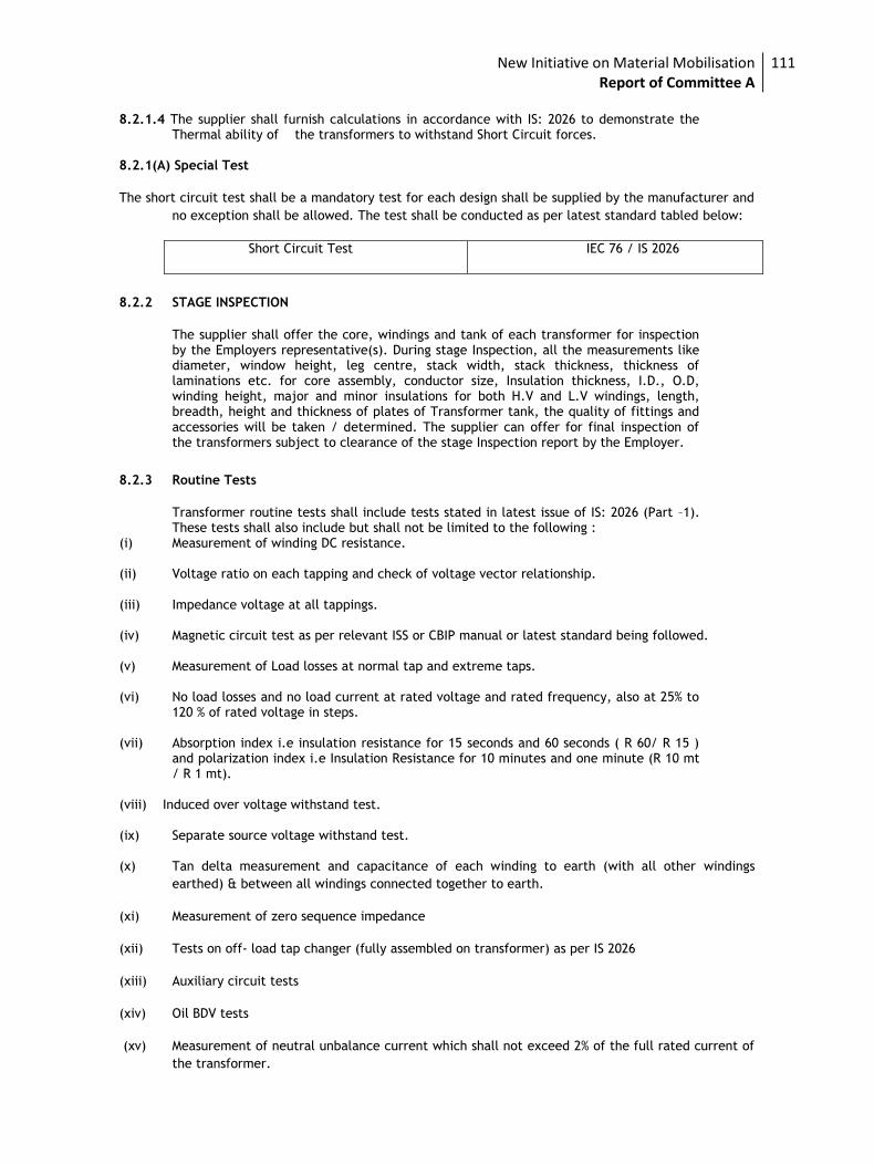
New Initiative on Material Mobilisation Report of Committee A
111
8.2.1.4 The supplier shall furnish calculations in accordance with IS: 2026 to demonstrate the
Thermal ability of the transformers to withstand Short Circuit forces. 8.2.1(A) Special Test
The short circuit test shall be a mandatory test for each design shall be supplied by the manufacturer and
no exception shall be allowed. The test shall be conducted as per latest standard tabled below:
Short Circuit Test IEC 76 / IS 2026
8.2.2 STAGE INSPECTION
The supplier shall offer the core, windings and tank of each transformer for inspection by the Employers representative(s). During stage Inspection, all the measurements like diameter, window height, leg centre, stack width, stack thickness, thickness of laminations etc. for core assembly, conductor size, Insulation thickness, I.D., O.D, winding height, major and minor insulations for both H.V and L.V windings, length, breadth, height and thickness of plates of Transformer tank, the quality of fittings and accessories will be taken / determined. The supplier can offer for final inspection of the transformers subject to clearance of the stage Inspection report by the Employer.
8.2.3 Routine Tests
Transformer routine tests shall include tests stated in latest issue of IS: 2026 (Part –1). These tests shall also include but shall not be limited to the following :
(i) Measurement of winding DC resistance. (ii) Voltage ratio on each tapping and check of voltage vector relationship. (iii) Impedance voltage at all tappings. (iv) Magnetic circuit test as per relevant ISS or CBIP manual or latest standard being followed. (v) Measurement of Load losses at normal tap and extreme taps. (vi) No load losses and no load current at rated voltage and rated frequency, also at 25% to
120 % of rated voltage in steps. (vii) Absorption index i.e insulation resistance for 15 seconds and 60 seconds ( R 60/ R 15 )
and polarization index i.e Insulation Resistance for 10 minutes and one minute (R 10 mt / R 1 mt).
(viii) Induced over voltage withstand test. (ix) Separate source voltage withstand test. (x) Tan delta measurement and capacitance of each winding to earth (with all other windings
earthed) & between all windings connected together to earth.
(xi) Measurement of zero sequence impedance
(xii) Tests on off- load tap changer (fully assembled on transformer) as per IS 2026
(xiii) Auxiliary circuit tests
(xiv) Oil BDV tests
(xv) Measurement of neutral unbalance current which shall not exceed 2% of the full rated current of
the transformer.
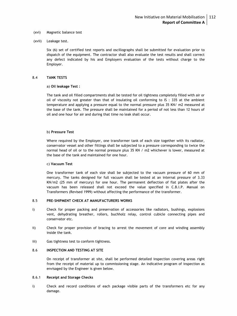
New Initiative on Material Mobilisation Report of Committee A
112
(xvi) Magnetic balance test
(xvii) Leakage test.
Six (6) set of certified test reports and oscillographs shall be submitted for evaluation prior to
dispatch of the equipment. The contractor shall also evaluate the test results and shall correct
any defect indicated by his and Employers evaluation of the tests without charge to the
Employer.
8.4 TANK TESTS
a) Oil leakage Test :
The tank and oil filled compartments shall be tested for oil tightness completely filled with air or
oil of viscosity not greater than that of insulating oil conforming to IS : 335 at the ambient
temperature and applying a pressure equal to the normal pressure plus 35 KN/ m2 measured at
the base of the tank. The pressure shall be maintained for a period of not less than 12 hours of
oil and one hour for air and during that time no leak shall occur.
b) Pressure Test
Where required by the Employer, one transformer tank of each size together with its radiator,
conservator vessel and other fittings shall be subjected to a pressure corresponding to twice the
normal head of oil or to the normal pressure plus 35 KN / m2 whichever is lower, measured at
the base of the tank and maintained for one hour.
c) Vacuum Test
One transformer tank of each size shall be subjected to the vacuum pressure of 60 mm of
mercury. The tanks designed for full vacuum shall be tested at an internal pressure of 3.33
KN/m2 (25 mm of mercury) for one hour. The permanent deflection of flat plates after the
vacuum has been released shall not exceed the value specified in C.B.I.P. Manual on
Transformers (Revised 1999) without affecting the performance of the transformer.
8.5 PRE-SHIPMENT CHECK AT MANUFACTURERS WORKS
i) Check for proper packing and preservation of accessories like radiators, bushings, explosions
vent, dehydrating breather, rollers, buchholz relay, control cubicle connecting pipes and
conservator etc.
ii) Check for proper provision of bracing to arrest the movement of core and winding assembly
inside the tank.
iii) Gas tightness test to conform tightness.
8.6 INSPECTION AND TESTING AT SITE
On receipt of transformer at site, shall be performed detailed inspection covering areas right
from the receipt of material up to commissioning stage. An indicative program of inspection as
envisaged by the Engineer is given below.
8.6.1 Receipt and Storage Checks
i) Check and record conditions of each package visible parts of the transformers etc for any
damage.
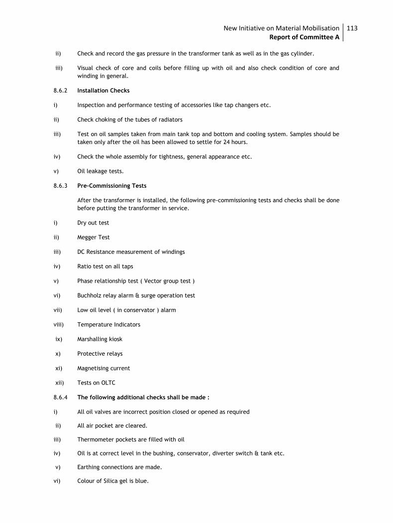
New Initiative on Material Mobilisation Report of Committee A
113
ii) Check and record the gas pressure in the transformer tank as well as in the gas cylinder.
iii) Visual check of core and coils before filling up with oil and also check condition of core and
winding in general.
8.6.2 Installation Checks
i) Inspection and performance testing of accessories like tap changers etc.
ii) Check choking of the tubes of radiators
iii) Test on oil samples taken from main tank top and bottom and cooling system. Samples should be
taken only after the oil has been allowed to settle for 24 hours.
iv) Check the whole assembly for tightness, general appearance etc.
v) Oil leakage tests.
8.6.3 Pre-Commissioning Tests
After the transformer is installed, the following pre-commissioning tests and checks shall be done
before putting the transformer in service.
i) Dry out test
ii) Megger Test
iii) DC Resistance measurement of windings
iv) Ratio test on all taps
v) Phase relationship test ( Vector group test )
vi) Buchholz relay alarm & surge operation test
vii) Low oil level ( in conservator ) alarm
viii) Temperature Indicators
ix) Marshalling kiosk
x) Protective relays
xi) Magnetising current
xii) Tests on OLTC
8.6.4 The following additional checks shall be made :
i) All oil valves are incorrect position closed or opened as required ii) All air pocket are cleared. iii) Thermometer pockets are filled with oil iv) Oil is at correct level in the bushing, conservator, diverter switch & tank etc. v) Earthing connections are made. vi) Colour of Silica gel is blue.
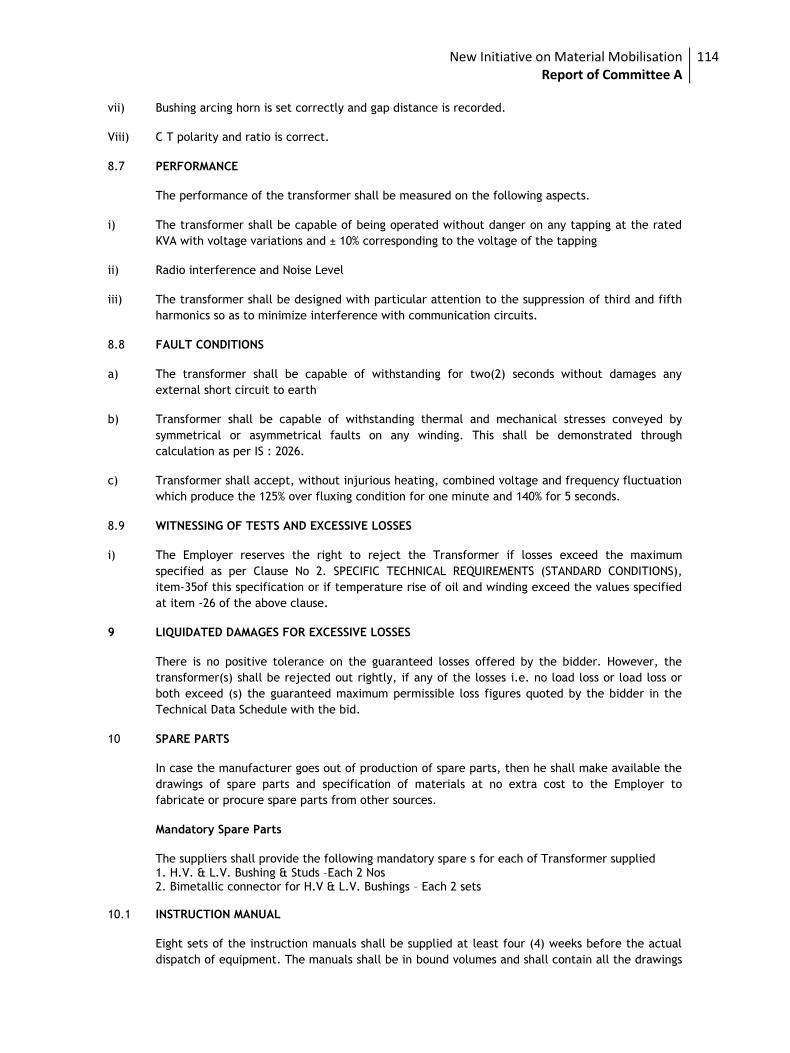
New Initiative on Material Mobilisation Report of Committee A
114
vii) Bushing arcing horn is set correctly and gap distance is recorded.
Viii) C T polarity and ratio is correct.
8.7 PERFORMANCE
The performance of the transformer shall be measured on the following aspects.
i) The transformer shall be capable of being operated without danger on any tapping at the rated
KVA with voltage variations and ± 10% corresponding to the voltage of the tapping
ii) Radio interference and Noise Level
iii) The transformer shall be designed with particular attention to the suppression of third and fifth
harmonics so as to minimize interference with communication circuits.
8.8 FAULT CONDITIONS
a) The transformer shall be capable of withstanding for two(2) seconds without damages any
external short circuit to earth
b) Transformer shall be capable of withstanding thermal and mechanical stresses conveyed by
symmetrical or asymmetrical faults on any winding. This shall be demonstrated through
calculation as per IS : 2026.
c) Transformer shall accept, without injurious heating, combined voltage and frequency fluctuation
which produce the 125% over fluxing condition for one minute and 140% for 5 seconds.
8.9 WITNESSING OF TESTS AND EXCESSIVE LOSSES
i) The Employer reserves the right to reject the Transformer if losses exceed the maximum
specified as per Clause No 2. SPECIFIC TECHNICAL REQUIREMENTS (STANDARD CONDITIONS),
item-35of this specification or if temperature rise of oil and winding exceed the values specified
at item -26 of the above clause.
9 LIQUIDATED DAMAGES FOR EXCESSIVE LOSSES
There is no positive tolerance on the guaranteed losses offered by the bidder. However, the
transformer(s) shall be rejected out rightly, if any of the losses i.e. no load loss or load loss or
both exceed (s) the guaranteed maximum permissible loss figures quoted by the bidder in the
Technical Data Schedule with the bid.
10 SPARE PARTS
In case the manufacturer goes out of production of spare parts, then he shall make available the
drawings of spare parts and specification of materials at no extra cost to the Employer to
fabricate or procure spare parts from other sources.
Mandatory Spare Parts
The suppliers shall provide the following mandatory spare s for each of Transformer supplied 1. H.V. & L.V. Bushing & Studs –Each 2 Nos 2. Bimetallic connector for H.V & L.V. Bushings – Each 2 sets 10.1 INSTRUCTION MANUAL
Eight sets of the instruction manuals shall be supplied at least four (4) weeks before the actual
dispatch of equipment. The manuals shall be in bound volumes and shall contain all the drawings
New Initiative on Material Mobilisation Report of Committee A
115
and information required for erection, operation and maintenance of the transformer. The
manuals shall include amongst other, the following particular:
a) Marked erection prints identifying the components, parts of the transformer as dispatched with
assembly drawings.
b) Detailed dimensions, assembly and description of all auxiliaries.
c) Detailed views of the core and winding assembly, winding connections and tapings tap changer
construction etc. These drawings are required for carrying out overhauling operation at site.
d) Salient technical particulars of the transformer.
e) Copies of all final approved drawings.
f) Detailed O&M instructions with periodical check lists and Performa etc.
10.2 COMPLETENESS OF EQUIPMENT
All fittings and accessories, which may not be specifically mentioned in the specification but
which are necessary for the satisfactory operation of the transformer, shall be deemed to be
included in the specification and shall be furnished by the supplier without extra charges. The
equipment shall be complete in all details whether such details are mentioned in the
specification or not, without any financial liability to the Employer under any circumstances.
11.0 TOOLS AND TACKLES
All the necessary tools and tackles required for normal operation & maintenance of the
transformers shall be supplied by the Contractor
12.0 COMMISSIONING
The equipment shall be commissioned as per CBIP manual, IS: 10028 and manufacturer’s
recommendations. All the related drawings and manuals shall be pre-requisite for release of final
payment.
New Initiative on Material Mobilisation Report of Committee A
116
ON LOAD TAP CHANGER FOR 33/11KV POWER
TRANSFORMER
The tapping range of On Load Tap Changer shall be +5% to -15% in steps of
1.25% each. The no of taps shall be 17.The On Load Tap Changer shall be
supplied with RTCC panel and AVR (Automatic Voltage Regulating Relay)
The Continuous current rating of the tap changer shall be based on connected
winding rating and shall have liberal and ample margin. Lower rated tap
changers connected in parallel are not acceptable.
The on-load tap changing equipment shall have the provision for mechanical
and electrical control from a local position and electrical control from a
remote position. For local mechanical operation, the operating handle shall be
brought outside the tank for operation from floor level with provision to lock
the handle in each tap position. Remote electrical operation shall have an
AUTO-MANUAL selection at the remote location. When selected AUTO, the tap
changing gear shall maintain steady voltage within practical limit on the
transformers secondary bus from which the reference shall not respond to
transient variation of voltage due to grid disturbance and system fault.
The required voltage relay shall not be sensitive to frequency variation and
shall be suitable for sensing voltage from the secondary of potential
transformers mounted on the 66KV, 33KV, or 11KV bus.
The tap changer shall be provided with over-current protection in order to
prevent the tap-change operation during a short circuit, which would to greatly
stress the contacts of the diverter switch. The function of protection shall be
arranged as follows;
(i) Whenever over current occurs, the control circuit for commanding OLTC motor
operation shall be blocked by the normally close contracts of the over current
relays.
(ii) If during tap change over current occurs, the OLTC motor circuit shall be
blocked through the mechanical cam switch, which is close from the very
beginning to the very end of every tap change operation and to the normally
open contacts of the over current relays. The stop action of the motor shall be
made through the motor brake contactor.
The design of the tap changing equipment shall be such that the mechanism
will not stop in any intermediate position; however, if the mechanism through
faulty operation does stop in an intermediate position, the full load must be
carried by the transformer without injury to the equipment. The mechanical
New Initiative on Material Mobilisation Report of Committee A
117
position indicator shall be equipped in the motor drive cubicle. The motor shall
be designed to be of step control. In any case the operation shall be of step by
step.
The voltage regulating relay shall be supplied together with the timer and
under voltage relay. The signal order from the voltage regulating relay to
execute the tap changer operation, when the regulating voltage is out of the
voltage regulating level shall be designed to be delayed by the adjustable
timer. If the control voltage abnormally falls, the movement of the tap changer
shall be locked by the contact of the under voltage relay, even if the contacts
of the voltage regulating relay are working.
The control circuit of the transformer shall be completely designed and
provisions shall be made for parallel operation with another transformer.
The following accessories, control and selector switches and other necessary
accessories shall be furnished.
Remote tap changer control board
(Placed in the control room)
Voltmeter
“AUTO-MANUAL” control switch
“RAISE-LOWER” control switch
Tap position indicator
Tap changer operation program indicator.
Transformer Tap Changer driving mechanism control cubicle
“REMOTE-LOCAL-TEST” selector switch
“AUTOMATIC-MANUAL” control switch
“RAISE-LOWER” control switch
Tap position indicator
Tap changer operation program indicator
Voltmeter
Tap change operation counter
Means for manual operation when power supply is lost
New Initiative on Material Mobilisation Report of Committee A
118
Single Phase Oil Immersed Distribution Transformers (Outdoor
Type)
1 SCOPE:
1.1 This specification covers design, engineering, manufacture, assembly, stage testing, inspection and testing before supply and delivery at site of oil immersed naturally cooled 11 kV/240 V, 11/√3 kV/240 V single phase distribution transformers for outdoor use.
1.2 The equipment shall conform in all respects to high standards of engineering, design and
workmanship and shall be capable of performing in continuous commercial operation in a manner
acceptable to the purchaser, who will interpret the meanings of drawings and specification and
shall have the power to reject any work or material which, in his judgment is not in accordance
therewith. The offered equipment shall be complete with all components necessary for their
effective and trouble free operation. Such components shall be deemed to be within the scope of
bidder’s supply irrespective of whether those are specifically brought out in this specification
and/or the commercial order or not.
1.3 The transformer and accessories shall be designed to facilitate operation, inspection,
maintenance and repairs. The design shall incorporate every precaution and provision for the
safety of equipment as well as staff engaged in the operation and maintenance of equipment.
1.4 All outdoor apparatus, including bushing insulators with their mountings, shall be designed so as
to avoid any accumulation of water.
1.5 STANDARD RATINGS
1.5.1 Standard ratings of single phase transformers shall be 5, 10, 16 and 25 kVA.
2 STANDARDS:
2.1 The materials shall conform in all respects to the relevant Indian Standard, with latest
amendments thereof unless otherwise specified herein; some of them are listed below.
2.2 Material conforming to other internationally accepted standards, which ensure equal or better quality than the standards mentioned above would also be acceptable. In case the bidder who wishes to offer material conforming to the other standards, salient points of difference between the standards adopted and the specific standards shall be clearly brought out in relevant schedule. Four copies of such standards with authentic English translations shall be furnished along with the offer.
3 SERVICE CONDITIONS:
Indian
Standards
Title InternationalStandards
IS -2026 Specification for Power Transformers IEC 76
IS 1180 (Part-I):
2014
Outdoor Type Oil Immersed Distribution
Transformers upto and including 2500kVA, 33kV-
Specification
IS 12444 Specification for Copper wire rod ASTM B-49
IS-335 Specification for Transformer/Mineral Oil IEC Pub 296
IS-5 Specification for colors for ready mixed paints
IS -104 Ready mixed paint, brushing zinc chromate, priming
IS-2099 Specification for high voltage porcelain bushing
IS-649 Testing for steel sheets and strips and magnetic
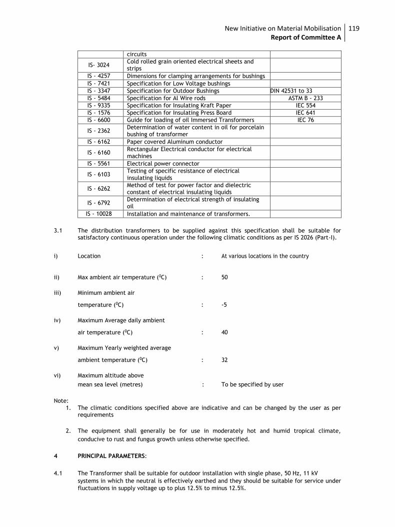
New Initiative on Material Mobilisation Report of Committee A
119
circuits
IS- 3024 Cold rolled grain oriented electrical sheets and strips
IS - 4257 Dimensions for clamping arrangements for bushings
IS - 7421 Specification for Low Voltage bushings
IS - 3347 Specification for Outdoor Bushings DIN 42531 to 33
IS - 5484 Specification for Al Wire rods ASTM B - 233
IS - 9335 Specification for Insulating Kraft Paper IEC 554
IS - 1576 Specification for Insulating Press Board IEC 641
IS - 6600 Guide for loading of oil Immersed Transformers IEC 76
IS - 2362 Determination of water content in oil for porcelain bushing of transformer
IS - 6162 Paper covered Aluminum conductor
IS - 6160 Rectangular Electrical conductor for electrical machines
IS - 5561 Electrical power connector
IS - 6103 Testing of specific resistance of electrical insulating liquids
IS - 6262 Method of test for power factor and dielectric constant of electrical insulating liquids
IS - 6792 Determination of electrical strength of insulating oil
IS - 10028 Installation and maintenance of transformers.
3.1 The distribution transformers to be supplied against this specification shall be suitable for
satisfactory continuous operation under the following climatic conditions as per IS 2026 (Part-I).
i) Location : At various locations in the country
ii) Max ambient air temperature (0C) : 50
iii) Minimum ambient air
temperature (0C) : -5
iv) Maximum Average daily ambient
air temperature (0C) : 40
v) Maximum Yearly weighted average
ambient temperature (0C) : 32
vi) Maximum altitude above
mean sea level (metres) : To be specified by user
Note: 1. The climatic conditions specified above are indicative and can be changed by the user as per
requirements
2. The equipment shall generally be for use in moderately hot and humid tropical climate,
conducive to rust and fungus growth unless otherwise specified.
4 PRINCIPAL PARAMETERS:
4.1 The Transformer shall be suitable for outdoor installation with single phase, 50 Hz, 11 kV systems in which the neutral is effectively earthed and they should be suitable for service under
fluctuations in supply voltage up to plus 12.5% to minus 12.5%.
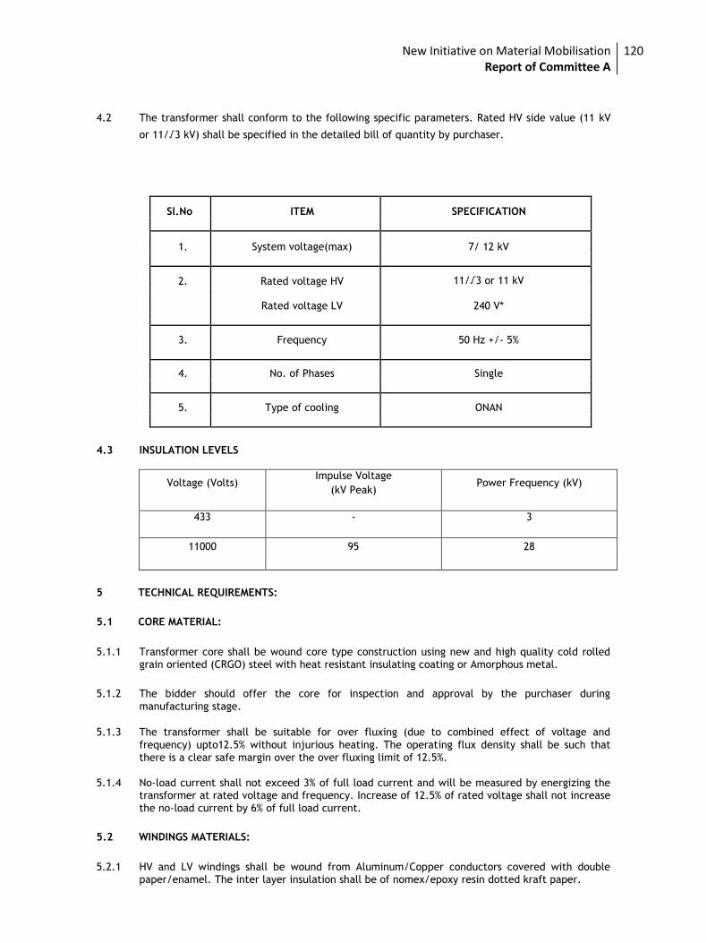
New Initiative on Material Mobilisation Report of Committee A
120
4.2 The transformer shall conform to the following specific parameters. Rated HV side value (11 kV
or 11/√3 kV) shall be specified in the detailed bill of quantity by purchaser.
Sl.No ITEM SPECIFICATION
1. System voltage(max) 7/ 12 kV
2. Rated voltage HV 11/√3 or 11 kV
Rated voltage LV 240 V*
3. Frequency 50 Hz +/- 5%
4. No. of Phases Single
5. Type of cooling ONAN
4.3 INSULATION LEVELS
Voltage (Volts) Impulse Voltage
(kV Peak) Power Frequency (kV)
433 - 3
11000 95 28
5 TECHNICAL REQUIREMENTS:
5.1 CORE MATERIAL:
5.1.1 Transformer core shall be wound core type construction using new and high quality cold rolled grain oriented (CRGO) steel with heat resistant insulating coating or Amorphous metal.
5.1.2 The bidder should offer the core for inspection and approval by the purchaser during
manufacturing stage.
5.1.3 The transformer shall be suitable for over fluxing (due to combined effect of voltage and
frequency) upto12.5% without injurious heating. The operating flux density shall be such that
there is a clear safe margin over the over fluxing limit of 12.5%.
5.1.4 No-load current shall not exceed 3% of full load current and will be measured by energizing the transformer at rated voltage and frequency. Increase of 12.5% of rated voltage shall not increase
the no-load current by 6% of full load current.
5.2 WINDINGS MATERIALS:
5.2.1 HV and LV windings shall be wound from Aluminum/Copper conductors covered with double paper/enamel. The inter layer insulation shall be of nomex/epoxy resin dotted kraft paper.
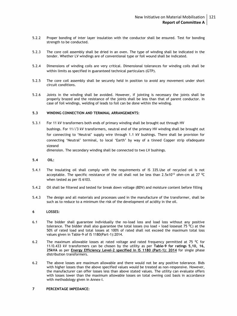
New Initiative on Material Mobilisation Report of Committee A
121
5.2.2 Proper bonding of inter layer insulation with the conductor shall be ensured. Test for bonding
strength to be conducted.
5.2.3 The core coil assembly shall be dried in an oven. The type of winding shall be indicated in the tender. Whether LV windings are of conventional type or foil wound shall be indicated.
5.2.4 Dimensions of winding coils are very critical. Dimensional tolerances for winding coils shall be
within limits as specified in guaranteed technical particulars (GTP).
5.2.5 The core coil assembly shall be securely held in position to avoid any movement under short
circuit conditions.
5.2.6 Joints in the winding shall be avoided. However, if jointing is necessary the joints shall be properly brazed and the resistance of the joints shall be less than that of parent conductor. In case of foil windings, welding of leads to foil can be done within the winding.
5.3 WINDING CONNECTION AND TERMINAL ARRANGEMENTS:
5.3.1 For 11 kV transformers both ends of primary winding shall be brought out through HV
bushings. For 11/√3 kV transformers, neutral end of the primary HV winding shall be brought out
for connecting to ‘Neutral’ supply wire through 1.1 kV bushings. There shall be provision for
connecting ‘Neutral’ terminal, to local ‘Earth’ by way of a tinned Copper strip ofadequate
sizeand dimension. The secondary winding shall be connected to two LV bushings.
5.4 OIL:
5.4.1 The insulating oil shall comply with the requirements of IS 335.Use of recycled oil is not
acceptable. The specific resistance of the oil shall not be less than 2.5x10¹² ohm-cm at 27 0C
when tested as per IS 6103. 5.4.2 Oil shall be filtered and tested for break down voltage (BDV) and moisture content before filling
5.4.3 The design and all materials and processes used in the manufacture of the transformer, shall be
such as to reduce to a minimum the risk of the development of acidity in the oil.
6 LOSSES:
6.1 The bidder shall guarantee individually the no-load loss and load loss without any positive tolerance. The bidder shall also guarantee the total losses (no load + load lossesat 75 0C) at the 50% of rated load and total losses at 100% of rated shall not exceed the maximum total loss values given in Table-9 of IS 1180(Part-1):2014.
6.2 The maximum allowable losses at rated voltage and rated frequency permitted at 75 0C for
11/0.433 kV transformers can be chosen by the utility as per Table-9 for ratings 5,10, 16, 25kVA as per Energy Efficiency Level-2 specified in IS 1180 (Part-1): 2014 for single phase distribution transformers.
6.2 The above losses are maximum allowable and there would not be any positive tolerance. Bids with higher losses than the above specified values would be treated as non-responsive. However, the manufacturer can offer losses less than above stated values. The utility can evaluate offers with losses lower than the maximum allowable losses on total owning cost basis in accordance with methodology given in Annex-I.
7 PERCENTAGE IMPEDANCE:
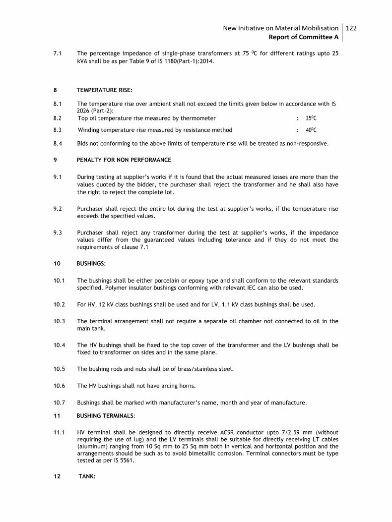
New Initiative on Material Mobilisation Report of Committee A
122
7.1 The percentage impedance of single-phase transformers at 75 0C for different ratings upto 25
kVA shall be as per Table 9 of IS 1180(Part-1):2014.
8 TEMPERATURE RISE: 8.1 The temperature rise over ambient shall not exceed the limits given below in accordance with IS 2026 (Part-2):
8.2 Top oil temperature rise measured by thermometer : 350C
8.3 Winding temperature rise measured by resistance method : 400C 8.4 Bids not conforming to the above limits of temperature rise will be treated as non-responsive.
9 PENALTY FOR NON PERFORMANCE
9.1 During testing at supplier’s works if it is found that the actual measured losses are more than the
values quoted by the bidder, the purchaser shall reject the transformer and he shall also have
the right to reject the complete lot.
9.2 Purchaser shall reject the entire lot during the test at supplier’s works, if the temperature rise
exceeds the specified values.
9.3 Purchaser shall reject any transformer during the test at supplier’s works, if the impedance
values differ from the guaranteed values including tolerance and if they do not meet the
requirements of clause 7.1
10 BUSHINGS:
10.1 The bushings shall be either porcelain or epoxy type and shall conform to the relevant standards
specified. Polymer insulator bushings conforming with relevant IEC can also be used.
10.2 For HV, 12 kV class bushings shall be used and for LV, 1.1 kV class bushings shall be used.
10.3 The terminal arrangement shall not require a separate oil chamber not connected to oil in the
main tank.
10.4 The HV bushings shall be fixed to the top cover of the transformer and the LV bushings shall be
fixed to transformer on sides and in the same plane.
10.5 The bushing rods and nuts shall be of brass/stainless steel.
10.6 The HV bushings shall not have arcing horns.
10.7 Bushings shall be marked with manufacturer’s name, month and year of manufacture.
11 BUSHING TERMINALS:
11.1 HV terminal shall be designed to directly receive ACSR conductor upto 7/2.59 mm (without requiring the use of lug) and the LV terminals shall be suitable for directly receiving LT cables (aluminum) ranging from 10 Sq mm to 25 Sq mm both in vertical and horizontal position and the
arrangements should be such as to avoid bimetallic corrosion. Terminal connectors must be type tested as per IS 5561.
12 TANK:
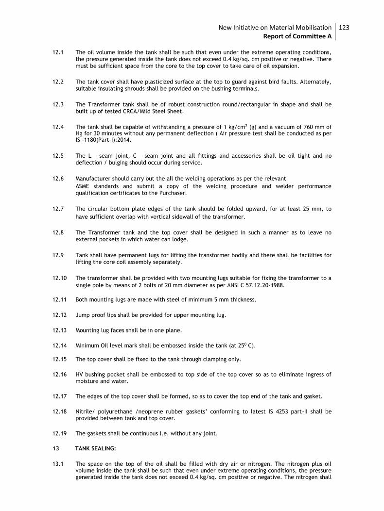
New Initiative on Material Mobilisation Report of Committee A
123
12.1 The oil volume inside the tank shall be such that even under the extreme operating conditions,
the pressure generated inside the tank does not exceed 0.4 kg/sq. cm positive or negative. There must be sufficient space from the core to the top cover to take care of oil expansion.
12.2 The tank cover shall have plasticized surface at the top to guard against bird faults. Alternately, suitable insulating shrouds shall be provided on the bushing terminals.
12.3 The Transformer tank shall be of robust construction round/rectangular in shape and shall be
built up of tested CRCA/Mild Steel Sheet.
12.4 The tank shall be capable of withstanding a pressure of 1 kg/cm2 (g) and a vacuum of 760 mm of
Hg for 30 minutes without any permanent deflection ( Air pressure test shall be conducted as per IS -1180(Part-I):2014.
12.5 The L - seam joint, C - seam joint and all fittings and accessories shall be oil tight and no deflection / bulging should occur during service.
12.6 Manufacturer should carry out the all the welding operations as per the relevant ASME standards and submit a copy of the welding procedure and welder performance qualification certificates to the Purchaser.
12.7 The circular bottom plate edges of the tank should be folded upward, for at least 25 mm, to
have sufficient overlap with vertical sidewall of the transformer.
12.8 The Transformer tank and the top cover shall be designed in such a manner as to leave no
external pockets in which water can lodge.
12.9 Tank shall have permanent lugs for lifting the transformer bodily and there shall be facilities for
lifting the core coil assembly separately.
12.10 The transformer shall be provided with two mounting lugs suitable for fixing the transformer to a
single pole by means of 2 bolts of 20 mm diameter as per ANSI C 57.12.20-1988.
12.11 Both mounting lugs are made with steel of minimum 5 mm thickness.
12.12 Jump proof lips shall be provided for upper mounting lug.
12.13 Mounting lug faces shall be in one plane.
12.14 Minimum Oil level mark shall be embossed inside the tank (at 250 C).
12.15 The top cover shall be fixed to the tank through clamping only.
12.16 HV bushing pocket shall be embossed to top side of the top cover so as to eliminate ingress of
moisture and water.
12.17 The edges of the top cover shall be formed, so as to cover the top end of the tank and gasket.
12.18 Nitrile/ polyurethane /neoprene rubber gaskets’ conforming to latest IS 4253 part-II shall be
provided between tank and top cover.
12.19 The gaskets shall be continuous i.e. without any joint.
13 TANK SEALING:
13.1 The space on the top of the oil shall be filled with dry air or nitrogen. The nitrogen plus oil
volume inside the tank shall be such that even under extreme operating conditions, the pressure generated inside the tank does not exceed 0.4 kg/sq. cm positive or negative. The nitrogen shall
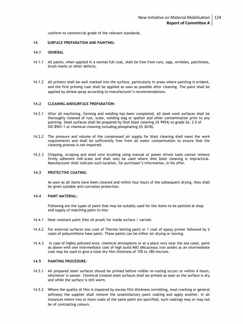
New Initiative on Material Mobilisation Report of Committee A
124
conform to commercial grade of the relevant standards.
14 SURFACE PREPARATION AND PAINTING:
14.1 GENERAL
14.1.1 All paints, when applied in a normal full coat, shall be free from runs, sags, wrinkles, patchiness,
brush marks or other defects.
14.1.2 All primers shall be well marked into the surface, particularly in areas where painting is evident,
and the first priming coat shall be applied as soon as possible after cleaning. The paint shall be
applied by airless spray according to manufacturer’s recommendations.
14.2 CLEANING ANDSURFACE PREPARATION:
14.2.1 After all machining, forming and welding has been completed, all steel work surfaces shall be thoroughly cleaned of rust, scale, welding slag or spatter and other contamination prior to any painting. Steel surfaces shall be prepared by Shot blast cleaning (IS 9954) to grade Sa. 2.5 of ISO 8501-1 or chemical cleaning including phosphating (IS 3618).
14.2.2 The pressure and volume of the compressed air supply for blast cleaning shall meet the work
requirements and shall be sufficiently free from all water contamination to ensure that the cleaning process is not impaired.
14.2.3 Chipping, scraping and steel wire brushing using manual or power driven tools cannot remove
firmly adherent mill-scale and shall only be used where shot blast cleaning is impractical. Manufacturer shall indicate such location, for purchaser’s information, in his offer.
14.3 PROTECTIVE COATING:
As soon as all items have been cleaned and within four hours of the subsequent drying, they shall
be given suitable anti-corrosion protection.
14.4 PAINT MATERIAL:
Following are the types of paint that may be suitably used for the items to be painted at shop
and supply of matching paint to site:
14.4.1 Heat resistant paint (Hot oil proof) for inside surface / varnish.
14.4.2 For external surfaces one coat of Thermo Setting paint or 1 coat of epoxy primer followed by 2
coats of polyurethene base paint. These paints can be either air-drying or stoving.
14.4.3 In case of highly polluted area, chemical atmosphere or at a place very near the sea coast, paint
as above with one intermediate coat of high build MIO (Micaceous iron oxide) as an intermediate coat may be used to give a total dry film thickness of 150 to 180 microns.
14.5 PAINTING PROCEDURE:
14.5.1 All prepared steel surfaces should be primed before visible re-rusting occurs or within 4 hours,
whichever is sooner. Chemical treated steel surfaces shall be primed as soon as the surface is dry
and while the surface is still warm.
14.5.2 Where the quality of film is impaired by excess film thickness (wrinkling, mud cracking or general
softness) the supplier shall remove the unsatisfactory paint coating and apply another. In all
instances where two or more coats of the same paint are specified, such coatings may or may not
be of contrasting colours.
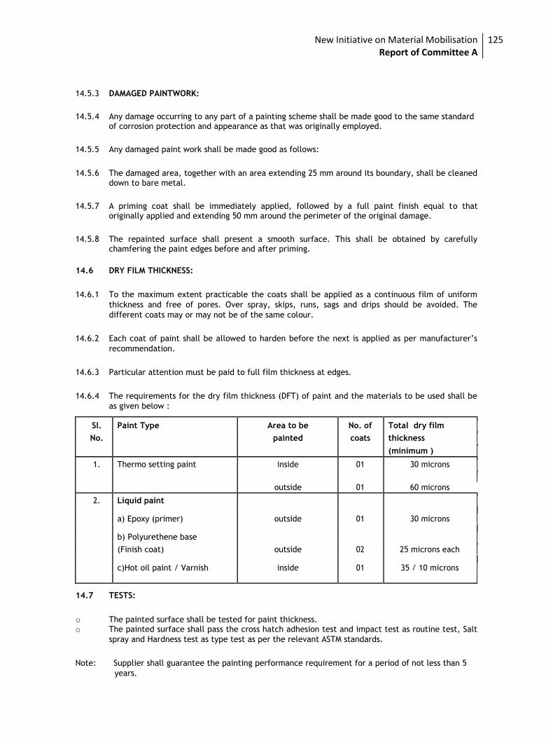
New Initiative on Material Mobilisation Report of Committee A
125
14.5.3 DAMAGED PAINTWORK:
14.5.4 Any damage occurring to any part of a painting scheme shall be made good to the same standard of corrosion protection and appearance as that was originally employed.
14.5.5 Any damaged paint work shall be made good as follows:
14.5.6 The damaged area, together with an area extending 25 mm around its boundary, shall be cleaned down to bare metal.
14.5.7 A priming coat shall be immediately applied, followed by a full paint finish equal to that originally applied and extending 50 mm around the perimeter of the original damage.
14.5.8 The repainted surface shall present a smooth surface. This shall be obtained by carefully chamfering the paint edges before and after priming.
14.6 DRY FILM THICKNESS:
14.6.1 To the maximum extent practicable the coats shall be applied as a continuous film of uniform
thickness and free of pores. Over spray, skips, runs, sags and drips should be avoided. The
different coats may or may not be of the same colour.
14.6.2 Each coat of paint shall be allowed to harden before the next is applied as per manufacturer’s
recommendation.
14.6.3 Particular attention must be paid to full film thickness at edges.
14.6.4 The requirements for the dry film thickness (DFT) of paint and the materials to be used shall be
as given below :
Sl. Paint Type Area to be No. of Total dry film
No. painted coats thickness
(minimum )
1. Thermo setting paint inside 01 30 microns
outside 01 60 microns
2. Liquid paint
a) Epoxy (primer) outside 01 30 microns
b) Polyurethene base
(Finish coat) outside 02 25 microns each
c)Hot oil paint / Varnish inside 01 35 / 10 microns
14.7 TESTS:
o The painted surface shall be tested for paint thickness. o The painted surface shall pass the cross hatch adhesion test and impact test as routine test, Salt
spray and Hardness test as type test as per the relevant ASTM standards.
Note: Supplier shall guarantee the painting performance requirement for a period of not less than 5
years.
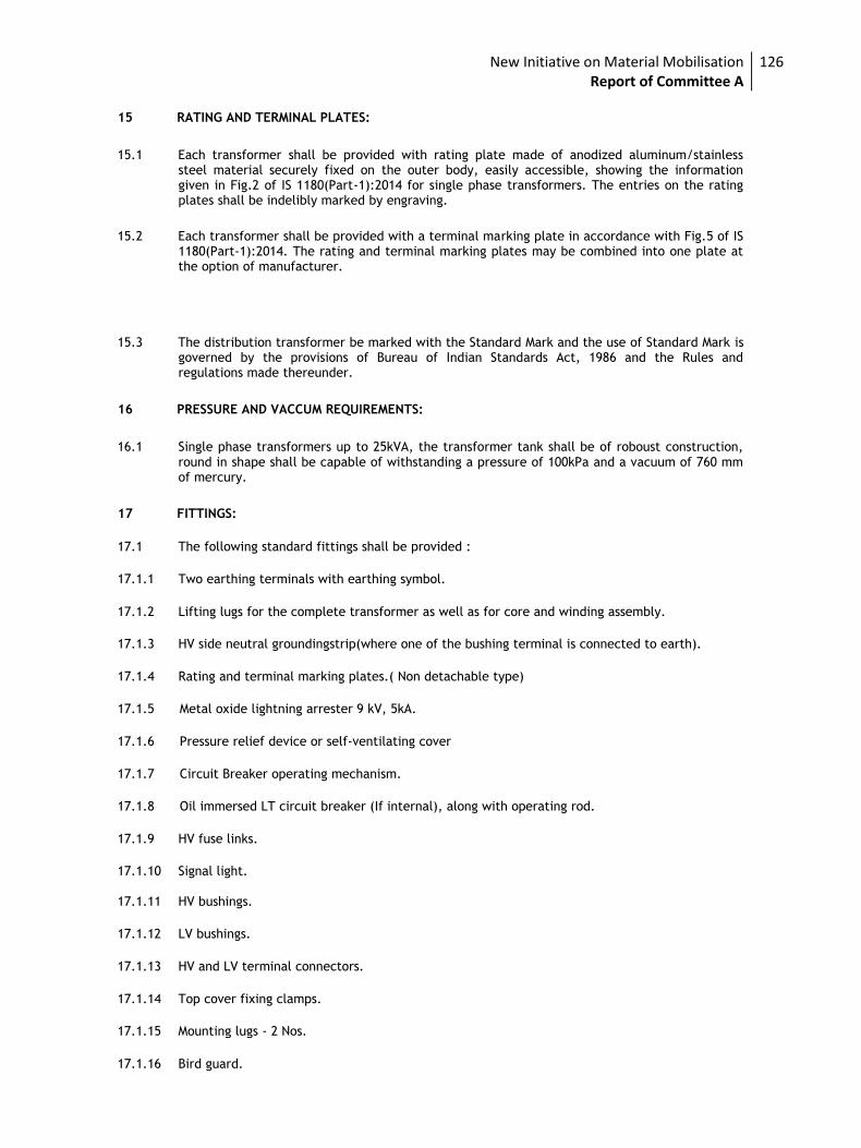
New Initiative on Material Mobilisation Report of Committee A
126
15 RATING AND TERMINAL PLATES:
15.1 Each transformer shall be provided with rating plate made of anodized aluminum/stainless steel material securely fixed on the outer body, easily accessible, showing the information given in Fig.2 of IS 1180(Part-1):2014 for single phase transformers. The entries on the rating plates shall be indelibly marked by engraving.
15.2 Each transformer shall be provided with a terminal marking plate in accordance with Fig.5 of IS 1180(Part-1):2014. The rating and terminal marking plates may be combined into one plate at the option of manufacturer.
15.3 The distribution transformer be marked with the Standard Mark and the use of Standard Mark is governed by the provisions of Bureau of Indian Standards Act, 1986 and the Rules and regulations made thereunder.
16 PRESSURE AND VACCUM REQUIREMENTS:
16.1 Single phase transformers up to 25kVA, the transformer tank shall be of roboust construction, round in shape shall be capable of withstanding a pressure of 100kPa and a vacuum of 760 mm of mercury.
17 FITTINGS:
17.1 The following standard fittings shall be provided :
17.1.1 Two earthing terminals with earthing symbol.
17.1.2 Lifting lugs for the complete transformer as well as for core and winding assembly.
17.1.3 HV side neutral groundingstrip(where one of the bushing terminal is connected to earth).
17.1.4 Rating and terminal marking plates.( Non detachable type)
17.1.5 Metal oxide lightning arrester 9 kV, 5kA.
17.1.6 Pressure relief device or self-ventilating cover
17.1.7 Circuit Breaker operating mechanism.
17.1.8 Oil immersed LT circuit breaker (If internal), along with operating rod.
17.1.9 HV fuse links.
17.1.10 Signal light.
17.1.11 HV bushings.
17.1.12 LV bushings.
17.1.13 HV and LV terminal connectors.
17.1.14 Top cover fixing clamps.
17.1.15 Mounting lugs - 2 Nos.
17.1.16 Bird guard.
New Initiative on Material Mobilisation Report of Committee A
127
17.1.17 LV earthing arrangement.
17.1.18 Any other fitting necessary for satisfactory performance of the product.
18 FASTENERS:
18.1 All bolts, studs, screw threads, pipe threads, bolt heads and nuts shall comply with the
appropriate Indian Standards for metric threads, or the technical equivalent.
18.2 Bolts or studs shall not be less than 6 mm in diameter except when used for small wiring
terminals.
18.3 All nuts and pins shall be adequately locked.
18.4 Wherever possible bolts shall be fitted in such a manner that in the event of failure of locking
resulting in the nuts working loose and falling off, the bolt will remain in position.
18.5 All ferrous bolts, nuts and washers placed in outdoor positions shall be treated to prevent corrosion, by hot dip galvanising, except high tensile steel bolts and spring washers which shall be electro-galvanised/ plated. Appropriate precautions shall be taken to prevent electrolytic action between dissimilar metals.
18.6 Each bolt or stud shall project at least one thread but not more than three threads through the
nut, except when otherwise approved for terminal board studs or relay stems. If bolts and nuts
are placed so that they are inaccessible by means of ordinary spanners, special spanners shall
be provided.
18.7 The length of the screwed portion of the bolts shall be such that no screw thread may form part
of a shear plane between members.
18.8 Taper washers shall be provided where necessary. Protective washers of suitable material shall
be provided front and back or the securing screws.
19 11 kV LIGHTNING ARRESTORS:
High surge capacity 9 kV, 5 kA Distribution class type lightning arrestor conforming to IS 3070
Part III shall be mounted on the transformer clamped securely to the tank, to protect the
transformer and associated line equipment from the occasional high voltage surges resulting
from lightning or switching operations. The earthing terminal of the lightning arrestors shall be
connected solidly to the transformer tank earthing terminal. Lightning arrestors with polymer
insulators in conformance with relevant IEC can also be used.
20 OVER LOAD CAPACITY:
20.1 The transformer shall be suitable for loading as per latest IS 6600.
21 TESTS:
21.1 All the equipment offered shall be fully type tested by the bidder as per the relevant standards
including the additional type tests mentioned at clause 23.The type test must have been
conducted on a transformer of same design during the last five years at the time of bidding. The
bidder shall furnish four sets of type test reports along with the offer. Offers without type test
reports will be treated as non-responsive.
21.2 Special tests other than type and routine tests, as agreed between purchaser and bidder shall
New Initiative on Material Mobilisation Report of Committee A
128
also be carried out as per the relevant standards
21.3 The test certificates for all routine and type tests for the transformers and also for the bushings
and transformer oil shall be submitted with the bid.
21.4 The procedure for testing shall be in accordance with IS 1180(Part-1): 2014/2026 as the case may
be except for temperature rise.
21.5 Before dispatch each of the completely assembled transformer shall be subjected to the routine
tests at the manufacturers works.
22 ROUTINE TESTS: 22.1 Ratio, polarity tests.
22.2 No load current and losses at service voltage and normal frequency.
22.3 Load losses at rated current and normal frequency.
22.4 Impedance Voltage test.
22.5 Resistance of windings cold (at or near the test bed temperature).
22.6 Insulation resistance.
22.7 Induced over voltage withstand test.
22.8 Separate source voltage withstand test.
22.9 Breaker coordination test.
22.10 Oil sample test (one sample per lot) to comply with IS 1866.
22.11 Air pressure test on empty tank as per IS 1180
23 TYPE TESTS TO BE CONDUCTED ON ONE UNIT:
In addition to the tests mentioned above following tests shall be conducted:
23.1 Temperature rise test for determining the maximum temperature rise after continuous full load
run. The ambient temperature and time of test should be stated in the test certificate.
23.2 Impulse voltage withstand test: As per IS 2026 part-III. Basic insulation level
(BIL) for 11 kV shall be 95 kV peak instead of 75 kV.
23.3 Air pressure test: As per IS 1180 (Part-I):2014.
23.4 Short circuit withstand test: Thermal and dynamic ability.
23.5 Oil samples (Post short circuit and temperature rise test)
23.6 Noise level measurement.
23.7 Permissible flux density and over fluxing withstand test.
23.8 Type test certificates for the tests carried out on prototype of same specifications shall be
New Initiative on Material Mobilisation Report of Committee A
129
submitted along with the bid.
23.9 The purchaser may select the transformer for type tests randomly.
23.10 Short Circuit Test and Impulse Voltage Withstand Test: The purchaser intends to procure
transformers designed and successfully tested for short circuit and impulse test. In case the
transformers proposed for supply against the order are not exactly as per the tested design, the
supplier shall be required to carry out the short circuit test and impulse voltage withstand test
at their own cost in the presence of the representative of the purchaser.
23.11 The supply shall be accepted only after such test is done successfully, as it confirms on
successful withstand of short circuit and healthiness of the active parts thereafter on un-
tanking after a short circuit test.
23.12 Apart from dynamic ability test, the transformers shall also be required to withstand thermal
ability test or thermal withstand ability will have to be established by way of calculations.
23.13 It may also be noted that the purchaser reserved the right to conduct short circuit test and
impulse voltage test in accordance with the IS, afresh on each ordered rating at purchaser’s
cost, even if the transformers of the same rating and similar design are already tested. This
test shall be carried out on a transformer to be selected by the purchaser either at their works
when they are offered in a lot for supply or randomly from the supplies already made to
purchaser’s Stores. The findings and conclusions of these tests shall be binding on the supplier.
24 TESTS AT SITE:
24.1 The purchaser reserves the right to conduct all tests on transformer after arrival at site and
the manufacturer shall guarantee test certificate figures under actual service conditions.
25 ACCEPTANCE TESTS:
25.1 The transformers shall be subjected to the following routine/ acceptance test in the presence
of purchaser’s representative at the place of manufacture before despatch without any extra
charges. The testing shall be carried out in accordance with IS 1180, Part-1 (2014) and IS 2026.
Checking of mass, dimensions, fitting and accessories, tank sheet thickness, oil quality,
material, finish and workmanship as per GTP/QA plan and contract drawings.
25.2 Physical verification of core coil assembly and measurement of flux density of one unit of each
rating, in every inspection with reference to short circuit test report.
25.3 All tests as specified in clause 22.
26 INSPECTION:
26.1 In respect of raw material such as core stampings, winding conductors, insulating paper and oil,
supplier shall use materials manufactured/supplied by standard manufacturers and furnish the
manufacturers’ test certificate as well as the proof of purchase from the manufacturers (excise
gate pass) for information of the purchaser. The bidder shall furnish following documents along
with their offer in respect to the raw materials :
26.1.1 Invoice of supplier.
26.1.2 Mill’s certificate.
26.1.3 Packing List.
New Initiative on Material Mobilisation Report of Committee A
130
26.1.4 Bill of landing.
26.1.5 Bill of entry certificate by custom.
26.2 To ensure about the quality of transformers, the inspection shall be carried out by the
purchaser’s representative at following stages:
26.2.1 Online anytime during receipt of raw material and manufacture/ assembly whenever the
purchaser desires.
26.2.2 When the raw material is received, and the assembly is in process in the shop floor.
26.2.3 At finished stage i.e. transformers are fully assembled and are ready for despatch.
26.3 After the main raw-materials i.e. core and coil materials and tanks are arranged and
transformers are taken for production on shop floor and a few assembly have been completed,
the firm shall intimate the purchaser in this regard, so that an officer for carrying out such
inspection could be deputed, as far as possible within seven days from the date of intimation.
During the stage inspection a few assembled core shall be dismantled (only in case of CRGO
material) to ensure that the CRGO laminations used are of good quality. Further, as and when
the transformers are ready for despatch, an offer intimating about the readiness of
transformers, for final inspection for carrying out tests as per relevant IS and as in clauses
above, shall be sent by the firm along with routine test certificates. The inspection shall
normally be arranged by the purchaser at the earliest after receipt of offer for pre-delivery
inspection.
26.4 In case of any defect/defective workmanship observed at any stage by the purchaser’s
inspecting officer; the same shall be pointed out to the firm in writing for taking remedial
measures. Further processing should only be done after clearance from the Inspecting
officer/purchaser.
26.5 All tests and inspection shall be carried out at the place of manufacture unless otherwise
specifically agreed upon by the manufacturer and purchaser at the time of purchase. The
manufacturer shall offer the inspector representing the purchaser all reasonable facilities,
without charges, to satisfy him that the material is being supplied in accordance with this
specification. This will include stage inspection during manufacturing stage as well as active
part inspection during acceptance tests.
26.6 The manufacturer shall provide all services to establish and maintain quality of workmanship in
his works and that of his sub-contractors to ensure the mechanical/electrical performance of
components, compliance with drawings, identification and acceptability of all materials, parts
and equipment as per latest quality standards of ISO 9000.
26.7 Along with the bid the manufacturer shall prepare Quality Assurance Plan (QAP) identifying the various stages of manufacture, quality checks performed at each stage and the customer hold
points. The document shall also furnish details of method of checking, inspection and
acceptance standards/values and get the approval of purchaser or his representative before
proceeding with manufacturing. However, purchaser or his representative shall have the right
to review the inspection reports, quality checks and results of manufacturer’s in house
inspection department which are not customer hold points and the manufacturer shall comply
with the remarks made by purchaser or his representative on such reviews with regards to
further testing, rectification or rejection etc. Manufacturer should submit the list of equipment
for testing along with latest calibration certificates to the purchaser.
26.8 Purchaser shall have every right to appoint a third party inspection to carry out the inspection
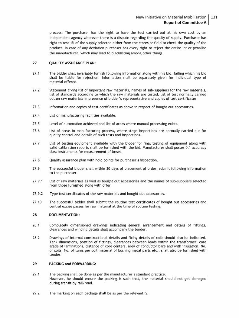
New Initiative on Material Mobilisation Report of Committee A
131
process. The purchaser has the right to have the test carried out at his own cost by an
independent agency wherever there is a dispute regarding the quality of supply. Purchaser has
right to test 1% of the supply selected either from the stores or field to check the quality of the
product. In case of any deviation purchaser has every right to reject the entire lot or penalise
the manufacturer, which may lead to blacklisting among other things.
27 QUALITY ASSURANCE PLAN:
27.1 The bidder shall invariably furnish following information along with his bid, failing which his bid shall be liable for rejection. Information shall be separately given for individual type of material offered.
27.2 Statement giving list of important raw materials, names of sub-suppliers for the raw materials, list of standards according to which the raw materials are tested, list of test normally carried out on raw materials in presence of bidder’s representative and copies of test certificates.
27.3 Information and copies of test certificates as above in respect of bought out accessories. 27.4 List of manufacturing facilities available. 27.5 Level of automation achieved and list of areas where manual processing exists.
27.6 List of areas in manufacturing process, where stage inspections are normally carried out for quality control and details of such tests and inspections.
27.7 List of testing equipment available with the bidder for final testing of equipment along with
valid calibration reports shall be furnished with the bid. Manufacturer shall posses 0.1 accuracy class instruments for measurement of losses.
27.8 Quality assurance plan with hold points for purchaser’s inspection. 27.9 The successful bidder shall within 30 days of placement of order, submit following information
to the purchaser. 27.9.1 List of raw materials as well as bought out accessories and the names of sub-suppliers selected
from those furnished along with offer. 27.9.2 Type test certificates of the raw materials and bought out accessories. 27.10 The successful bidder shall submit the routine test certificates of bought out accessories and
central excise passes for raw material at the time of routine testing.
28 DOCUMENTATION:
28.1 Completely dimensioned drawings indicating general arrangement and details of fittings, clearances and winding details shall accompany the tender.
28.2 Drawings of internal constructional details and fixing details of coils should also be indicated. Tank dimensions, position of fittings, clearances between leads within the transformer, core grade of laminations, distance of core centers, area of conductor bare and with insulation. No. of coils, No. of turns per coil material of bushing metal parts etc., shall also be furnished with tender.
29 PACKING and FORWARDING:
29.1 The packing shall be done as per the manufacturer’s standard practice. However, he should ensure the packing is such that, the material should not get damaged
during transit by rail/road.
29.2 The marking on each package shall be as per the relevant IS.
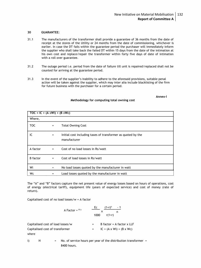
New Initiative on Material Mobilisation Report of Committee A
132
30 GUARANTEE: 31.1 The manufacturers of the transformer shall provide a guarantee of 36 months from the date of
receipt at the stores of the Utility or 24 months from the date of commissioning, whichever is
earlier. In case the DT fails within the guarantee period the purchaser will immediately inform
the supplier who shall take back the failed DT within 15 days from the date of the intimation at
his own cost and replace/repair the transformer within forty five days of date of intimation
with a roll over guarantee.
31.2 The outage period i.e. period from the date of failure till unit is repaired/replaced shall not be
counted for arriving at the guarantee period.
31.3 In the event of the supplier’s inability to adhere to the aforesaid provisions, suitable penal action will be taken against the supplier, which may inter alia include blacklisting of the firm for future business with the purchaser for a certain period.
Annex-I
Methodology for computing total owning cost
TOC = IC + (A xWi) + (B xWc)
Where,
TOC = Total Owning Cost
IC = Initial cost including taxes of transformer as quoted by the
manufacturer
A factor = Cost of no load losses in Rs/watt
B factor = Cost of load losses in Rs/watt
Wi = No load losses quoted by the manufacturer in watt
Wc = Load losses quoted by the manufacturer in watt
The “A” and “B” factors capture the net present value of energy losses based on hours of operations, cost
of energy (electrical tariff), equipment life (years of expected service) and cost of money (rate of
return).
Capitalised cost of no load losses/w = A factor
A Factor = H x
Ec
x
(1+r)n - 1
r(1+r) n
1000
Capitalised cost of load losses/w = B factor = A factor x LLF
Capitalised cost of transformer = IC + (A x Wi) + (B x Wc)
where
i) H = No. of service hours per year of the distribution transformer =
8400 hours.
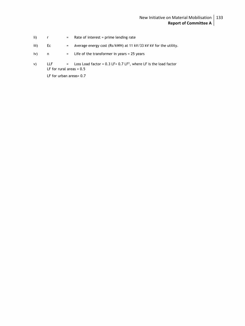
New Initiative on Material Mobilisation Report of Committee A
133
ii) r = Rate of interest = prime lending rate
iii) Ec = Average energy cost (Rs/kWH) at 11 kV/33 kV kV for the utility.
iv) n = Life of the transformer in years = 25 years
v) LLF = Loss Load factor = 0.3 LF+ 0.7 LF2, where LF is the load factor LF for rural areas = 0.5
LF for urban areas= 0.7
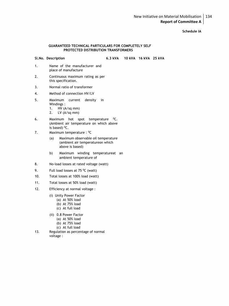
New Initiative on Material Mobilisation Report of Committee A
134
Schedule IA
GUARANTEED TECHNICAL PARTICULARS FOR COMPLETELY SELF PROTECTED DISTRIBUTION TRANSFORMERS
Sl.No. Description 6.3 kVA 10 kVA 16 kVA 25 kVA 1. Name of the manufacturer and
place of manufacture 2. Continuous maximum rating as per
this specification. 3. Normal ratio of transformer 4. Method of connection HV/LV 5. Maximum current density in
Windings : 1. HV (A/sq mm) 2. LV (A/sq mm)
6. Maximum hot spot temperature 0C.
(Ambient air temperature on which above
is based) 0C. 7. Maximum temperature : 0C
(a) Maximum observable oil temperature
(ambient air temperatureon which
above is based)
b) Maximum winding temperatureat an
ambient temperature of 8. No-load losses at rated voltage (watt) 9. Full load losses at 75 0C (watt) 10. Total losses at 100% load (watt) 11. Total losses at 50% load (watt) 12. Efficiency at normal voltage :
(i) Unity Power Factor (a) At 50% load (b) At 75% load (c) At full load
(ii) 0.8 Power Factor
(a) At 50% load (b) At 75% load (c) At full load
13. Regulation as percentage of normal
voltage :
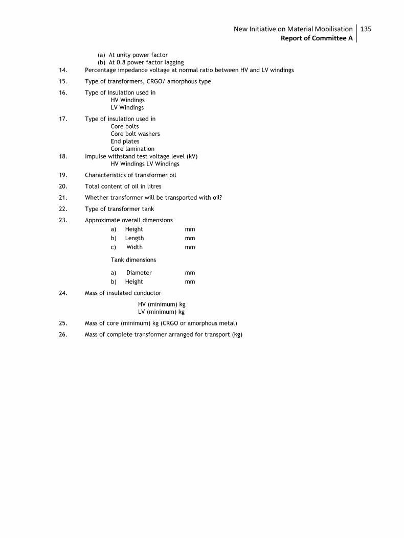
New Initiative on Material Mobilisation Report of Committee A
135
(a) At unity power factor (b) At 0.8 power factor lagging
14. Percentage impedance voltage at normal ratio between HV and LV windings 15. Type of transformers, CRGO/ amorphous type 16. Type of Insulation used in
HV Windings LV Windings
17. Type of insulation used in
Core bolts Core bolt washers End plates Core lamination
18. Impulse withstand test voltage level (kV) HV Windings LV Windings
19. Characteristics of transformer oil 20. Total content of oil in litres 21. Whether transformer will be transported with oil? 22. Type of transformer tank 23. Approximate overall dimensions
a) Height mm
b) Length mm
c) Width mm
Tank dimensions
a) Diameter mm
b) Height mm 24. Mass of insulated conductor
HV (minimum) kg LV (minimum) kg
25. Mass of core (minimum) kg (CRGO or amorphous metal) 26. Mass of complete transformer arranged for transport (kg)
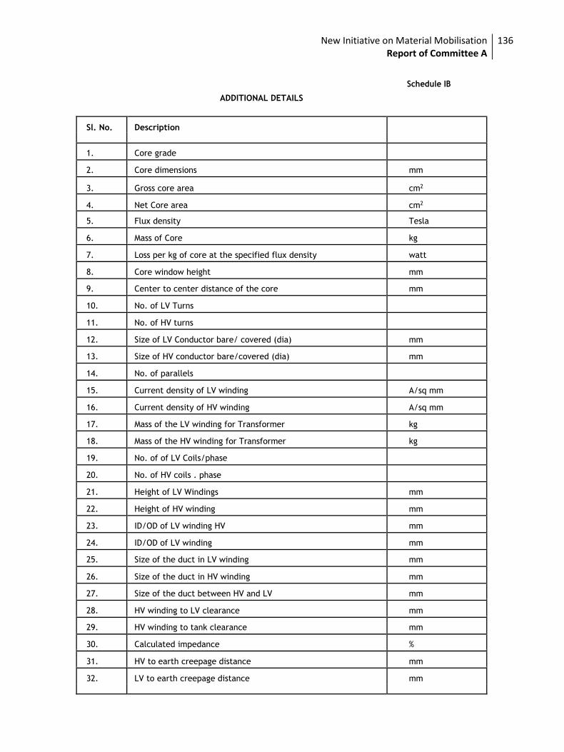
New Initiative on Material Mobilisation Report of Committee A
136
Schedule IB
ADDITIONAL DETAILS
Sl. No. Description
1. Core grade
2. Core dimensions mm
3. Gross core area cm2
4. Net Core area cm2
5. Flux density Tesla
6. Mass of Core kg
7. Loss per kg of core at the specified flux density watt
8. Core window height mm
9. Center to center distance of the core mm
10. No. of LV Turns
11. No. of HV turns
12. Size of LV Conductor bare/ covered (dia) mm
13. Size of HV conductor bare/covered (dia) mm
14. No. of parallels
15. Current density of LV winding A/sq mm
16. Current density of HV winding A/sq mm
17. Mass of the LV winding for Transformer kg
18. Mass of the HV winding for Transformer kg
19. No. of of LV Coils/phase
20. No. of HV coils . phase
21. Height of LV Windings mm
22. Height of HV winding mm
23. ID/OD of LV winding HV mm
24. ID/OD of LV winding mm
25. Size of the duct in LV winding mm
26. Size of the duct in HV winding mm
27. Size of the duct between HV and LV mm
28. HV winding to LV clearance mm
29. HV winding to tank clearance mm
30. Calculated impedance %
31. HV to earth creepage distance mm
32. LV to earth creepage distance mm
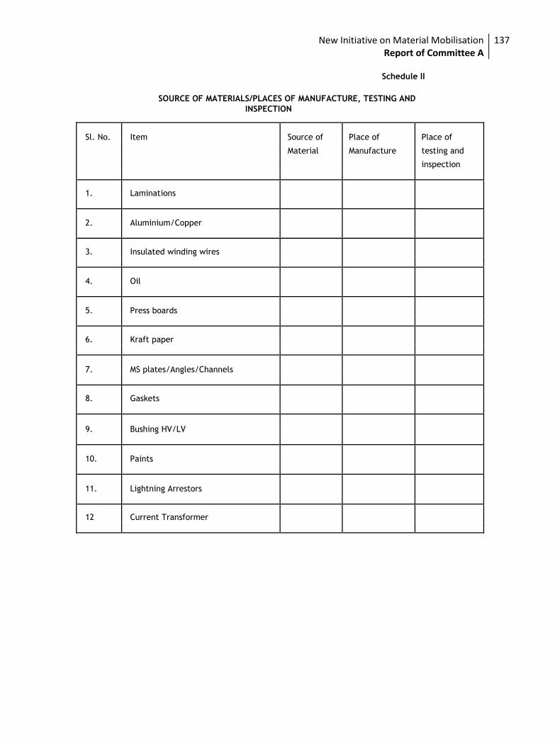
New Initiative on Material Mobilisation Report of Committee A
137
Schedule II
SOURCE OF MATERIALS/PLACES OF MANUFACTURE, TESTING AND
INSPECTION
Sl. No. Item Source of Place of Place of
Material Manufacture testing and
inspection
1. Laminations
2. Aluminium/Copper
3. Insulated winding wires
4. Oil
5. Press boards
6. Kraft paper
7. MS plates/Angles/Channels
8. Gaskets
9. Bushing HV/LV
10. Paints
11. Lightning Arrestors
12 Current Transformer
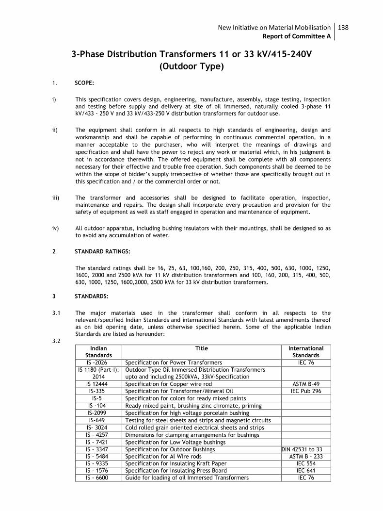
New Initiative on Material Mobilisation Report of Committee A
138
3-Phase Distribution Transformers 11 or 33 kV/415-240V
(Outdoor Type)
1. SCOPE:
i) This specification covers design, engineering, manufacture, assembly, stage testing, inspection
and testing before supply and delivery at site of oil immersed, naturally cooled 3-phase 11
kV/433 - 250 V and 33 kV/433-250 V distribution transformers for outdoor use.
ii) The equipment shall conform in all respects to high standards of engineering, design and
workmanship and shall be capable of performing in continuous commercial operation, in a
manner acceptable to the purchaser, who will interpret the meanings of drawings and
specification and shall have the power to reject any work or material which, in his judgment is
not in accordance therewith. The offered equipment shall be complete with all components
necessary for their effective and trouble free operation. Such components shall be deemed to be
within the scope of bidder’s supply irrespective of whether those are specifically brought out in
this specification and / or the commercial order or not.
iii) The transformer and accessories shall be designed to facilitate operation, inspection,
maintenance and repairs. The design shall incorporate every precaution and provision for the
safety of equipment as well as staff engaged in operation and maintenance of equipment.
iv) All outdoor apparatus, including bushing insulators with their mountings, shall be designed so as
to avoid any accumulation of water.
2 STANDARD RATINGS:
The standard ratings shall be 16, 25, 63, 100,160, 200, 250, 315, 400, 500, 630, 1000, 1250,
1600, 2000 and 2500 kVA for 11 kV distribution transformers and 100, 160, 200, 315, 400, 500,
630, 1000, 1250, 1600,2000, 2500 kVA for 33 kV distribution transformers.
3 STANDARDS:
3.1 The major materials used in the transformer shall conform in all respects to the
relevant/specified Indian Standards and international Standards with latest amendments thereof
as on bid opening date, unless otherwise specified herein. Some of the applicable Indian
Standards are listed as hereunder:
3.2
Indian
Standards
Title International
Standards
IS -2026 Specification for Power Transformers IEC 76
IS 1180 (Part-I):
2014
Outdoor Type Oil Immersed Distribution Transformers
upto and including 2500kVA, 33kV-Specification
IS 12444 Specification for Copper wire rod ASTM B-49
IS-335 Specification for Transformer/Mineral Oil IEC Pub 296
IS-5 Specification for colors for ready mixed paints
IS -104 Ready mixed paint, brushing zinc chromate, priming
IS-2099 Specification for high voltage porcelain bushing
IS-649 Testing for steel sheets and strips and magnetic circuits
IS- 3024 Cold rolled grain oriented electrical sheets and strips
IS - 4257 Dimensions for clamping arrangements for bushings
IS - 7421 Specification for Low Voltage bushings
IS - 3347 Specification for Outdoor Bushings DIN 42531 to 33
IS - 5484 Specification for Al Wire rods ASTM B - 233
IS - 9335 Specification for Insulating Kraft Paper IEC 554
IS - 1576 Specification for Insulating Press Board IEC 641
IS - 6600 Guide for loading of oil Immersed Transformers IEC 76
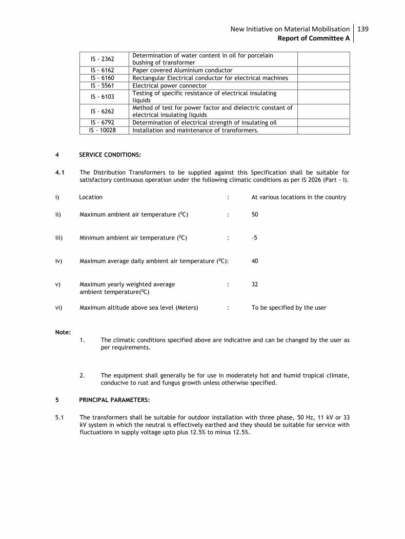
New Initiative on Material Mobilisation Report of Committee A
139
IS - 2362 Determination of water content in oil for porcelain bushing of transformer
IS - 6162 Paper covered Aluminium conductor
IS - 6160 Rectangular Electrical conductor for electrical machines
IS - 5561 Electrical power connector
IS - 6103 Testing of specific resistance of electrical insulating liquids
IS - 6262 Method of test for power factor and dielectric constant of electrical insulating liquids
IS - 6792 Determination of electrical strength of insulating oil
IS - 10028 Installation and maintenance of transformers.
4 SERVICE CONDITIONS:
4.1 The Distribution Transformers to be supplied against this Specification shall be suitable for
satisfactory continuous operation under the following climatic conditions as per IS 2026 (Part - I).
i) Location : At various locations in the country
ii) Maximum ambient air temperature (0C) : 50
iii) Minimum ambient air temperature (0C) : -5
iv) Maximum average daily ambient air temperature (0C): 40
v) Maximum yearly weighted average : 32
ambient temperature(0C)
vi) Maximum altitude above sea level (Meters) : To be specified by the user
Note: 1. The climatic conditions specified above are indicative and can be changed by the user as
per requirements.
2. The equipment shall generally be for use in moderately hot and humid tropical climate,
conducive to rust and fungus growth unless otherwise specified.
5 PRINCIPAL PARAMETERS:
5.1 The transformers shall be suitable for outdoor installation with three phase, 50 Hz, 11 kV or 33
kV system in which the neutral is effectively earthed and they should be suitable for service with
fluctuations in supply voltage upto plus 12.5% to minus 12.5%.
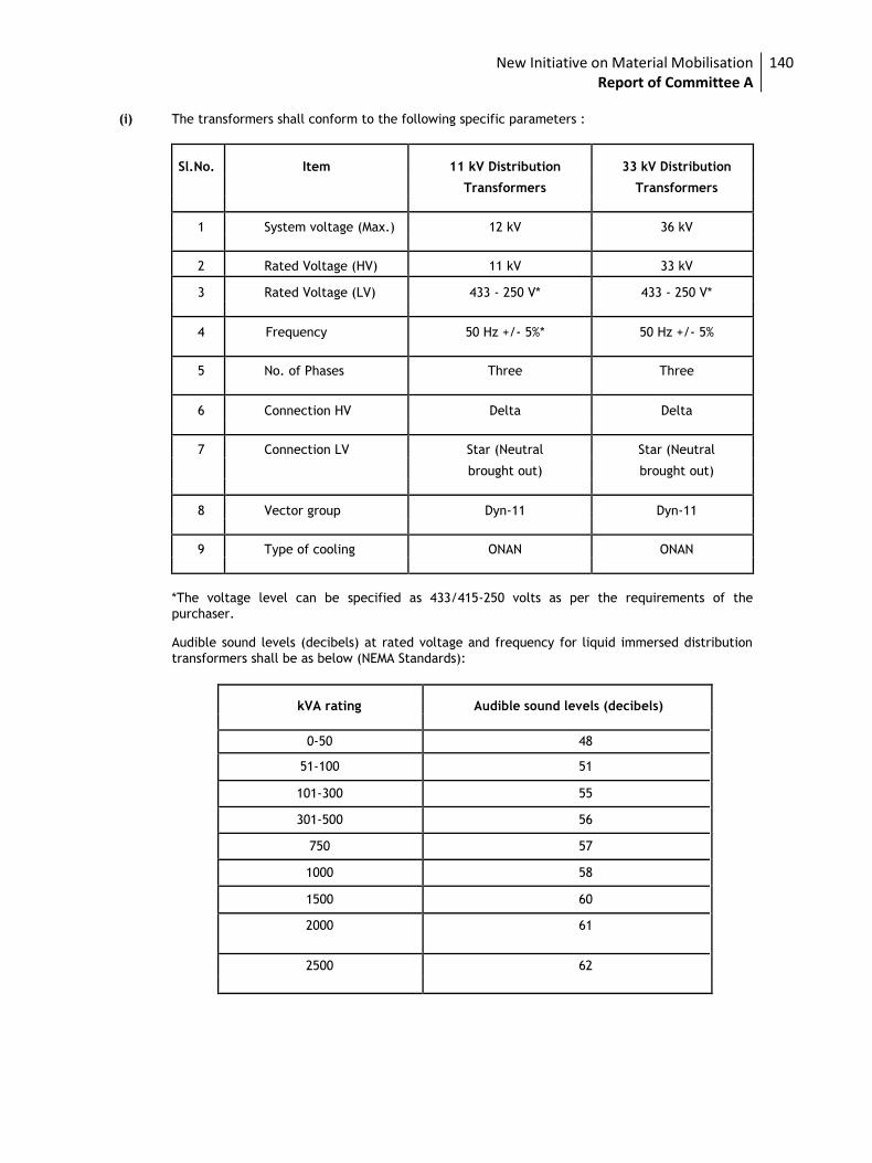
New Initiative on Material Mobilisation Report of Committee A
140
(i) The transformers shall conform to the following specific parameters :
Sl.No. Item 11 kV Distribution 33 kV Distribution
Transformers Transformers
1 System voltage (Max.) 12 kV 36 kV
2 Rated Voltage (HV) 11 kV 33 kV
3 Rated Voltage (LV) 433 - 250 V* 433 - 250 V*
4 Frequency 50 Hz +/- 5%* 50 Hz +/- 5%
5 No. of Phases Three Three
6 Connection HV Delta Delta
7 Connection LV Star (Neutral Star (Neutral
brought out) brought out)
8 Vector group Dyn-11 Dyn-11
9 Type of cooling ONAN ONAN
*The voltage level can be specified as 433/415-250 volts as per the requirements of the
purchaser.
Audible sound levels (decibels) at rated voltage and frequency for liquid immersed distribution
transformers shall be as below (NEMA Standards):
kVA rating Audible sound levels (decibels)
0-50 48
51-100 51
101-300 55
301-500 56
750 57
1000 58
1500 60
2000 61
2500 62
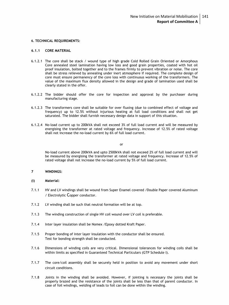
New Initiative on Material Mobilisation Report of Committee A
141
6. TECHNICAL REQUIREMENTS:
6.1.1 CORE MATERIAL
6.1.2.1 The core shall be stack / wound type of high grade Cold Rolled Grain Oriented or Amorphous Core annealed steel lamination having low loss and good grain properties, coated with hot oil proof insulation, bolted together and to the frames firmly to prevent vibration or noise. The core shall be stress relieved by annealing under inert atmosphere if required. The complete design of core must ensure permanency of the core loss with continuous working of the transformers. The value of the maximum flux density allowed in the design and grade of lamination used shall be clearly stated in the offer.
6.1.2.2 The bidder should offer the core for inspection and approval by the purchaser during manufacturing stage.
6.1.2.3 The transformers core shall be suitable for over fluxing (due to combined effect of voltage and frequency) up to 12.5% without injurious heating at full load conditions and shall not get saturated. The bidder shall furnish necessary design data in support of this situation.
6.1.2.4 No-load current up to 200kVA shall not exceed 3% of full load current and will be measured by
energising the transformer at rated voltage and frequency. Increase of 12.5% of rated voltage shall not increase the no-load current by 6% of full load current.
or No-load current above 200kVA and upto 2500kVA shall not exceed 2% of full load current and will be measured by energising the transformer at rated voltage and frequency. Increase of 12.5% of rated voltage shall not increase the no-load current by 5% of full load current.
7 WINDINGS:
(i) Material:
7.1.1 HV and LV windings shall be wound from Super Enamel covered /Double Paper covered Aluminum
/ Electrolytic Copper conductor.
7.1.2 LV winding shall be such that neutral formation will be at top.
7.1.3 The winding construction of single HV coil wound over LV coil is preferable.
7.1.4 Inter layer insulation shall be Nomex /Epoxy dotted Kraft Paper.
7.1.5 Proper bonding of inter layer insulation with the conductor shall be ensured. Test for bonding strength shall be conducted.
7.1.6 Dimensions of winding coils are very critical. Dimensional tolerances for winding coils shall be
within limits as specified in Guaranteed Technical Particulars (GTP Schedule I).
7.1.7 The core/coil assembly shall be securely held in position to avoid any movement under short
circuit conditions.
7.1.8 Joints in the winding shall be avoided. However, if jointing is necessary the joints shall be properly brazed and the resistance of the joints shall be less than that of parent conductor. In case of foil windings, welding of leads to foil can be done within the winding.
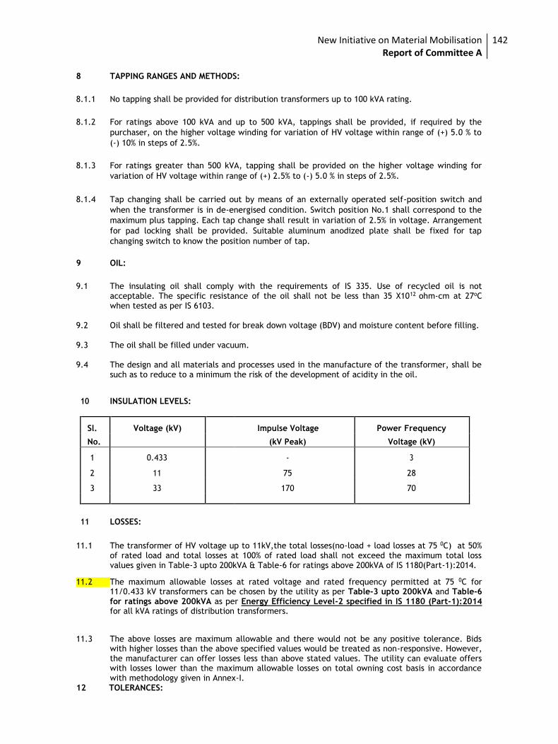
New Initiative on Material Mobilisation Report of Committee A
142
8 TAPPING RANGES AND METHODS:
8.1.1 No tapping shall be provided for distribution transformers up to 100 kVA rating.
8.1.2 For ratings above 100 kVA and up to 500 kVA, tappings shall be provided, if required by the
purchaser, on the higher voltage winding for variation of HV voltage within range of (+) 5.0 % to
(-) 10% in steps of 2.5%.
8.1.3 For ratings greater than 500 kVA, tapping shall be provided on the higher voltage winding for
variation of HV voltage within range of (+) 2.5% to (-) 5.0 % in steps of 2.5%.
8.1.4 Tap changing shall be carried out by means of an externally operated self-position switch and
when the transformer is in de-energised condition. Switch position No.1 shall correspond to the
maximum plus tapping. Each tap change shall result in variation of 2.5% in voltage. Arrangement
for pad locking shall be provided. Suitable aluminum anodized plate shall be fixed for tap
changing switch to know the position number of tap.
9 OIL:
9.1 The insulating oil shall comply with the requirements of IS 335. Use of recycled oil is not acceptable. The specific resistance of the oil shall not be less than 35 X1012 ohm-cm at 27oC when tested as per IS 6103.
9.2 Oil shall be filtered and tested for break down voltage (BDV) and moisture content before filling. 9.3 The oil shall be filled under vacuum. 9.4 The design and all materials and processes used in the manufacture of the transformer, shall be
such as to reduce to a minimum the risk of the development of acidity in the oil.
10 INSULATION LEVELS:
Sl. Voltage (kV) Impulse Voltage Power Frequency
No. (kV Peak) Voltage (kV)
1 0.433 - 3
2 11 75 28
3 33 170 70
11
LOSSES:
11.1 The transformer of HV voltage up to 11kV,the total losses(no-load + load losses at 75 0C) at 50% of rated load and total losses at 100% of rated load shall not exceed the maximum total loss values given in Table-3 upto 200kVA & Table-6 for ratings above 200kVA of IS 1180(Part-1):2014.
11.2 The maximum allowable losses at rated voltage and rated frequency permitted at 75 0C for
11/0.433 kV transformers can be chosen by the utility as per Table-3 upto 200kVA and Table-6 for ratings above 200kVA as per Energy Efficiency Level-2 specified in IS 1180 (Part-1):2014 for all kVA ratings of distribution transformers.
11.3 The above losses are maximum allowable and there would not be any positive tolerance. Bids with higher losses than the above specified values would be treated as non-responsive. However, the manufacturer can offer losses less than above stated values. The utility can evaluate offers with losses lower than the maximum allowable losses on total owning cost basis in accordance with methodology given in Annex-I.
12 TOLERANCES:
New Initiative on Material Mobilisation Report of Committee A
143
12.1 No positive tolerance shall be allowed on the maximum losses displayed on the label for both 50%
and 100% loading values. 13 PERCENTAGE IMPEDANCE:
The percentage impedance of transformers at 75 0C for different ratings upto 200 kVA shall be as
per Table 3 and for ratings beyond 200 kVA shall be as per Table 6 of IS 1180(Part-1):2014.
14 Temperature rise: The temperature rise over ambient shall not exceed the limits given below:
14.1 Top oil temperature rise measured by thermometer : 35 0C
14.2 Winding temperature rise measured by resistance method : 40 0C 14.3 The transformer shall be capable of giving continuous rated output without exceeding the
specified temperature rise. Bidder shall submit the calculation sheet in this regard.
15 PENALTY FOR NON PERFORMANCE:
15.1 During testing at supplier’s works if it is found that the actual measured losses are more than the
values quoted by the bidder, the purchaser shall reject the transformer and he shall also have
the right to reject the complete lot.
15.2 Purchaser shall reject the entire lot during the test at supplier’s works, if the temperature rise
exceeds the specified values.
15.3 Purchaser shall reject any transformer during the test at supplier’s works, if the impedance
values differ from the guaranteed values including tolerance.
16 INSULATION MATERIAL:
16.1 Electrical grade insulation epoxy dotted Kraft Paper/Nomex and pressboard of standard make or
any other superior material subject to approval of the purchaser shall be used.
16.2 All spacers, axial wedges / runners used in windings shall be made of pre-compressed
Pressboard-solid, conforming to type B 3.1 of IEC 641-3-2. In case of cross-over coil winding of HV
all spacers shall be properly sheared and dovetail punched to ensure proper locking. All axial
wedges / runners shall be properly milled to dovetail shape so that they pass through the
designed spacers freely. Insulation shearing, cutting, milling and punching operations shall be
carried out in such a way, that there should not be any burr and dimensional variations.
17.1 TANK:
Transformer tank construction shall conform in all respect to clause 15 of IS 1180(Part-1):2014.
The internal clearance of tank shall be such, that it shall facilitate easy lifting of core with coils from the tank without dismantling LV bushings.
All joints of tank and fittings shall be oil tight and no bulging should occur during service.
Inside of tank shall be painted with varnish/hot oil resistant paint.
The top cover of the tank shall be slightly sloping to drain rain water.
The tank plate and the lifting lugs shall be of such strength that the complete transformer filled with oil may be lifted by means of lifting shackle.
Manufacturer should carry out all welding operations as per the relevant ASME standards and
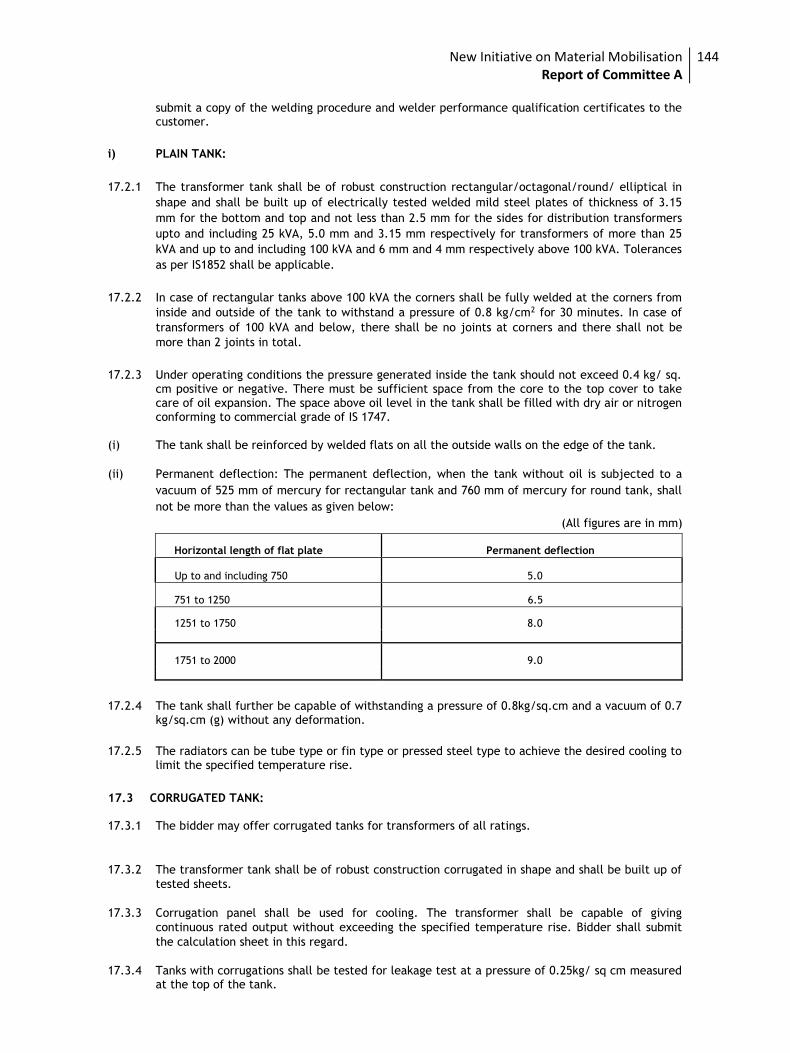
New Initiative on Material Mobilisation Report of Committee A
144
submit a copy of the welding procedure and welder performance qualification certificates to the customer.
i) PLAIN TANK:
17.2.1 The transformer tank shall be of robust construction rectangular/octagonal/round/ elliptical in
shape and shall be built up of electrically tested welded mild steel plates of thickness of 3.15
mm for the bottom and top and not less than 2.5 mm for the sides for distribution transformers
upto and including 25 kVA, 5.0 mm and 3.15 mm respectively for transformers of more than 25
kVA and up to and including 100 kVA and 6 mm and 4 mm respectively above 100 kVA. Tolerances
as per IS1852 shall be applicable.
17.2.2 In case of rectangular tanks above 100 kVA the corners shall be fully welded at the corners from
inside and outside of the tank to withstand a pressure of 0.8 kg/cm2 for 30 minutes. In case of
transformers of 100 kVA and below, there shall be no joints at corners and there shall not be
more than 2 joints in total.
17.2.3 Under operating conditions the pressure generated inside the tank should not exceed 0.4 kg/ sq. cm positive or negative. There must be sufficient space from the core to the top cover to take care of oil expansion. The space above oil level in the tank shall be filled with dry air or nitrogen conforming to commercial grade of IS 1747.
(i) The tank shall be reinforced by welded flats on all the outside walls on the edge of the tank.
(ii) Permanent deflection: The permanent deflection, when the tank without oil is subjected to a
vacuum of 525 mm of mercury for rectangular tank and 760 mm of mercury for round tank, shall
not be more than the values as given below:
(All figures are in mm)
Horizontal length of flat plate Permanent deflection
Up to and including 750 5.0
751 to 1250 6.5
1251 to 1750 8.0
1751 to 2000 9.0
17.2.4 The tank shall further be capable of withstanding a pressure of 0.8kg/sq.cm and a vacuum of 0.7 kg/sq.cm (g) without any deformation.
17.2.5 The radiators can be tube type or fin type or pressed steel type to achieve the desired cooling to
limit the specified temperature rise.
17.3 CORRUGATED TANK: 17.3.1 The bidder may offer corrugated tanks for transformers of all ratings.
17.3.2 The transformer tank shall be of robust construction corrugated in shape and shall be built up of
tested sheets.
17.3.3 Corrugation panel shall be used for cooling. The transformer shall be capable of giving
continuous rated output without exceeding the specified temperature rise. Bidder shall submit
the calculation sheet in this regard.
17.3.4 Tanks with corrugations shall be tested for leakage test at a pressure of 0.25kg/ sq cm measured at the top of the tank.
New Initiative on Material Mobilisation Report of Committee A
145
17.3.5 The transformers with corrugation should be provided with a pallet for transportation, the dimensions of which should be more than the length and width of the transformer tank with corrugations.
18 CONSERVATOR: (i) Transformers of rating 63 kVA and above with plain tank construction, the provision of
conservator is mandatory. For corrugated tank and sealed type transformers with or without
inert gas cushion, conservator is not required.
(ii) When a conservator is provided, oil gauge and the plain or dehydrating breathing device shall be
fitted to the conservator which shall also be provided with a drain plug and a filling hole [32 mm
(1¼”)] normal size thread with cover. In addition, the cover of the main tank shall be provided
with an air release plug.
(iii) The dehydrating agent shall be silica gel. The moisture absorption shall be indicated by a change
in the colour of the silica gel crystals which should be easily visible from a distance. Volume of
breather shall be suitable for 500g of silica gel conforming to IS 3401 for transformers upto 200
kVA and 1 kg for transformers above 200 kVA .
(iv) The capacity of a conservator tank shall be designed keeping in view the total quantity of oil and
its contraction and expansion due to temperature variations. The total volume of conservator
shall be such as to contain10% quantity of the oil. Normally 3% quantity the oil shall be contained
in the conservator.
(v) The cover of main tank shall be provided with an air release plug to enable air trapped within to
be released, unless the conservator is so located as to eliminate the possibility of air being
trapped within the main tank.
(vi) The inside diameter of the pipe connecting the conservator to the main tank should be within 20
to 50 mm and it should be projected into the conservator so that its end is approximately 20 mm
above the bottom of the conservator so as to create a sump for collection of impurities. The
minimum oil level (corresponding to -5 0C) should be above the sump level.
19 SURFACE PREPARATION AND PAINTING:
(i) GENERAL
19.1.1 All paints, when applied in a normal full coat, shall be free from runs, sags, wrinkles, patchiness,
brush marks or other defects.
19.1.2 All primers shall be well marked into the surface, particularly in areas where painting is evident
and the first priming coat shall be applied as soon as possible after cleaning. The paint shall be
applied by airless spray according to manufacturer’s recommendations. However, where ever
airless spray is not possible, conventional spray be used with prior approval of purchaser.
19.2 CLEANING AND SURFACE PREPARATION:
a) After all machining, forming and welding has been completed, all steel work surfaces shall be
thoroughly cleaned of rust, scale, welding slag or spatter and other contamination prior to any
painting.
New Initiative on Material Mobilisation Report of Committee A
146
b) Steel surfaces shall be prepared by shot blast cleaning (IS9954) to grade Sq.
2.5 of ISO 8501-1 or chemical cleaning including phosphating of the appropriate quality (IS 3618).
c) Chipping, scraping and steel wire brushing using manual or power driven tools cannot remove
firmly adherent mill-scale. These methods shall only be used where blast cleaning is impractical.
Manufacturer to clearly explain such areas in his technical offer.
19.3 PROTECTIVE COATING:
19.3.1 As soon as all items have been cleaned and within four hours of the subsequent drying, they shall
be given suitable anti-corrosion protection.
19.4 PAINT MATERIAL:
i) Following are the types of paint which may be suitably used for the items to be painted at shop
and supply of matching paint to site:
Heat resistant paint (Hot oil proof) for inside surface
ii) For external surfaces one coat of thermo setting powder paint or one coat of epoxy primer
followed by two coats of synthetic enamel/polyurethene base paint. These paints can be either
air drying or stoving.
iii) For highly polluted areas, chemical atmosphere or for places very near to the sea coast, paint as
above with one coat of high build Micaceous iron oxide (MIO) as an intermediate coat may be
used.
19.5 PAINTING PROCEDURE:
i) All prepared steel surfaces should be primed before visible re-rusting occurs or within 4 hours,
whichever is sooner. Chemical treated steel surfaces shall be primed as soon as the surface is dry
and while the surface is still warm.
ii) Where the quality of film is impaired by excess film thickness (wrinkling, mud cracking or general
softness) the supplier shall remove the unsatisfactory paint coating and apply another coating. As
a general rule, dry film thickness should not exceed the specified minimum dry film thickens by
more than 25%.
19.6 DAMAGED PAINTWORK:
(i) Any damage occurring to any part of a painting scheme shall be made good to the same standard of corrosion protection and appearance as that was originally applied.
(ii) Any damaged paint work shall be made good as follows:
19.6.2.1 The damaged area, together with an area extending 25 mm around its boundary, shall be cleaned
down to bare metal.
19.6.2.2 A priming coat shall be immediately applied, followed by a full paint finish equal to that originally applied and extending 50 mm around the perimeter of the original damage.
19.6.2.3 The repainted surface shall present a smooth surface. This shall be obtained by carefully
chamfering the paint edges before and after priming.
19.7 DRY FILM THICKNESS:
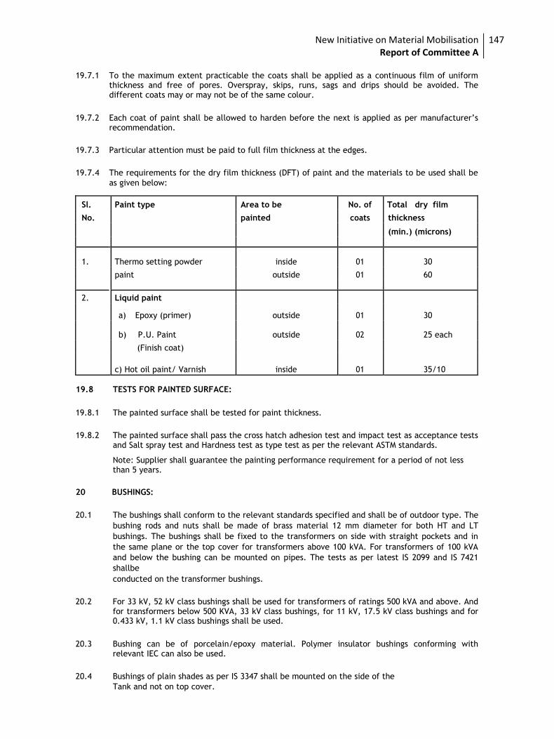
New Initiative on Material Mobilisation Report of Committee A
147
19.7.1 To the maximum extent practicable the coats shall be applied as a continuous film of uniform
thickness and free of pores. Overspray, skips, runs, sags and drips should be avoided. The different coats may or may not be of the same colour.
19.7.2 Each coat of paint shall be allowed to harden before the next is applied as per manufacturer’s recommendation.
19.7.3 Particular attention must be paid to full film thickness at the edges.
19.7.4 The requirements for the dry film thickness (DFT) of paint and the materials to be used shall be
as given below:
Sl. Paint type Area to be No. of Total dry film
No. painted coats thickness
(min.) (microns)
1. Thermo setting powder inside 01 30
paint outside 01 60
2. Liquid paint
a) Epoxy (primer) outside 01 30
b) P.U. Paint outside 02 25 each
(Finish coat)
c) Hot oil paint/ Varnish inside 01 35/10
19.8 TESTS FOR PAINTED SURFACE:
19.8.1 The painted surface shall be tested for paint thickness.
19.8.2 The painted surface shall pass the cross hatch adhesion test and impact test as acceptance tests and Salt spray test and Hardness test as type test as per the relevant ASTM standards.
Note: Supplier shall guarantee the painting performance requirement for a period of not less than 5 years.
20 BUSHINGS:
20.1 The bushings shall conform to the relevant standards specified and shall be of outdoor type. The
bushing rods and nuts shall be made of brass material 12 mm diameter for both HT and LT
bushings. The bushings shall be fixed to the transformers on side with straight pockets and in
the same plane or the top cover for transformers above 100 kVA. For transformers of 100 kVA
and below the bushing can be mounted on pipes. The tests as per latest IS 2099 and IS 7421
shallbe conducted on the transformer bushings.
20.2 For 33 kV, 52 kV class bushings shall be used for transformers of ratings 500 kVA and above. And for transformers below 500 KVA, 33 kV class bushings, for 11 kV, 17.5 kV class bushings and for 0.433 kV, 1.1 kV class bushings shall be used.
20.3 Bushing can be of porcelain/epoxy material. Polymer insulator bushings conforming with relevant IEC can also be used.
20.4 Bushings of plain shades as per IS 3347 shall be mounted on the side of the Tank and not on top cover.
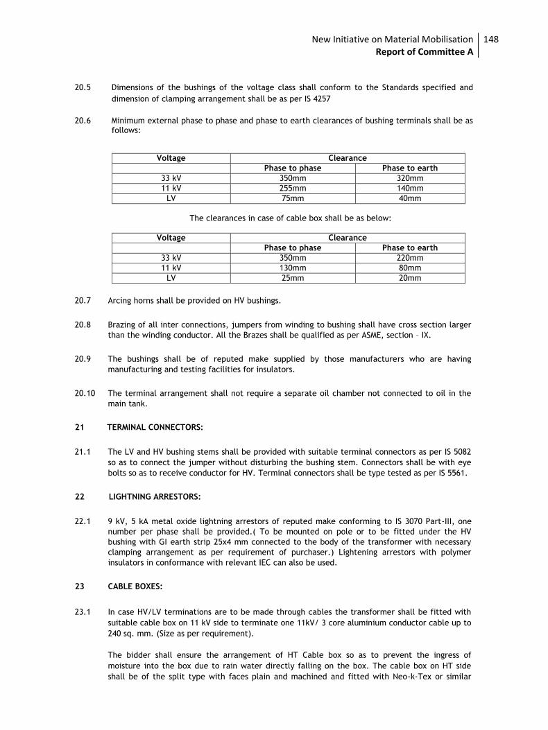
New Initiative on Material Mobilisation Report of Committee A
148
20.5 Dimensions of the bushings of the voltage class shall conform to the Standards specified and
dimension of clamping arrangement shall be as per IS 4257
20.6 Minimum external phase to phase and phase to earth clearances of bushing terminals shall be as
follows:
Voltage Clearance
Phase to phase Phase to earth
33 kV 350mm 320mm
11 kV 255mm 140mm
LV 75mm 40mm
The clearances in case of cable box shall be as below:
Voltage Clearance
Phase to phase Phase to earth
33 kV 350mm 220mm
11 kV 130mm 80mm
LV 25mm 20mm
20.7 Arcing horns shall be provided on HV bushings.
20.8 Brazing of all inter connections, jumpers from winding to bushing shall have cross section larger
than the winding conductor. All the Brazes shall be qualified as per ASME, section – IX.
20.9 The bushings shall be of reputed make supplied by those manufacturers who are having
manufacturing and testing facilities for insulators.
20.10 The terminal arrangement shall not require a separate oil chamber not connected to oil in the
main tank.
21 TERMINAL CONNECTORS:
21.1 The LV and HV bushing stems shall be provided with suitable terminal connectors as per IS 5082
so as to connect the jumper without disturbing the bushing stem. Connectors shall be with eye
bolts so as to receive conductor for HV. Terminal connectors shall be type tested as per IS 5561.
22 LIGHTNING ARRESTORS:
22.1 9 kV, 5 kA metal oxide lightning arrestors of reputed make conforming to IS 3070 Part-III, one
number per phase shall be provided.( To be mounted on pole or to be fitted under the HV
bushing with GI earth strip 25x4 mm connected to the body of the transformer with necessary
clamping arrangement as per requirement of purchaser.) Lightening arrestors with polymer
insulators in conformance with relevant IEC can also be used.
23 CABLE BOXES:
23.1 In case HV/LV terminations are to be made through cables the transformer shall be fitted with
suitable cable box on 11 kV side to terminate one 11kV/ 3 core aluminium conductor cable up to
240 sq. mm. (Size as per requirement).
The bidder shall ensure the arrangement of HT Cable box so as to prevent the ingress of
moisture into the box due to rain water directly falling on the box. The cable box on HT side
shall be of the split type with faces plain and machined and fitted with Neo-k-Tex or similar
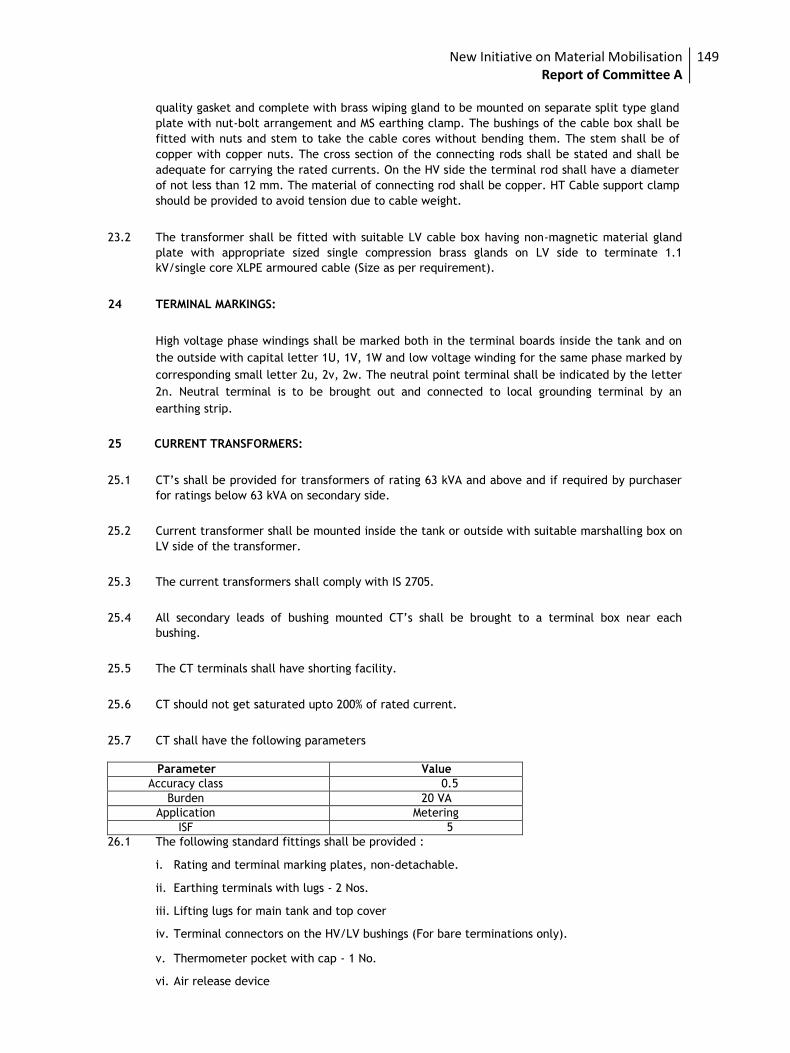
New Initiative on Material Mobilisation Report of Committee A
149
quality gasket and complete with brass wiping gland to be mounted on separate split type gland
plate with nut-bolt arrangement and MS earthing clamp. The bushings of the cable box shall be
fitted with nuts and stem to take the cable cores without bending them. The stem shall be of
copper with copper nuts. The cross section of the connecting rods shall be stated and shall be
adequate for carrying the rated currents. On the HV side the terminal rod shall have a diameter
of not less than 12 mm. The material of connecting rod shall be copper. HT Cable support clamp
should be provided to avoid tension due to cable weight.
23.2 The transformer shall be fitted with suitable LV cable box having non-magnetic material gland
plate with appropriate sized single compression brass glands on LV side to terminate 1.1
kV/single core XLPE armoured cable (Size as per requirement).
24 TERMINAL MARKINGS:
High voltage phase windings shall be marked both in the terminal boards inside the tank and on
the outside with capital letter 1U, 1V, 1W and low voltage winding for the same phase marked by
corresponding small letter 2u, 2v, 2w. The neutral point terminal shall be indicated by the letter
2n. Neutral terminal is to be brought out and connected to local grounding terminal by an
earthing strip.
25 CURRENT TRANSFORMERS:
25.1 CT’s shall be provided for transformers of rating 63 kVA and above and if required by purchaser
for ratings below 63 kVA on secondary side.
25.2 Current transformer shall be mounted inside the tank or outside with suitable marshalling box on
LV side of the transformer.
25.3 The current transformers shall comply with IS 2705.
25.4 All secondary leads of bushing mounted CT’s shall be brought to a terminal box near each
bushing.
25.5 The CT terminals shall have shorting facility.
25.6 CT should not get saturated upto 200% of rated current.
25.7 CT shall have the following parameters
Parameter Value
Accuracy class 0.5
Burden 20 VA
Application Metering
ISF 5
26.1 The following standard fittings shall be provided : i. Rating and terminal marking plates, non-detachable. ii. Earthing terminals with lugs - 2 Nos. iii. Lifting lugs for main tank and top cover iv. Terminal connectors on the HV/LV bushings (For bare terminations only). v. Thermometer pocket with cap - 1 No. vi. Air release device
New Initiative on Material Mobilisation Report of Committee A
150
vii. HV bushings - 3 Nos. viii. LV bushings - 4 Nos. ix. Pulling lugs x. Stiffener xi. Radiators - No. and length may be mentioned (as per heat dissipation calculations)/
corrugations. xii. Arcing horns or 9 kV, 5 kA lightning arrestors on HT side - 3 No. xiii. Prismatic oil level gauge.
xiv. Drain cum sampling valve.
xv. Top filter valve
xvi. Oil filling hole having p. 1- ¼ ‘’ thread with plug and drain plug on the conservator.
xvii. Silicagel breather
xviii. Base channel 75x40 mm for up to 100 kVA and 100 mmx50 mm above 100 kVA, 460 mm long with holes to make them suitable for fixing on a platform or plinth.
xix. 4 No. rollers for transformers of 200 kVA and above.
xx. Pressure relief device or explosion vent. 27 FASTENERS:
27.1 All bolts, studs, screw threads, pipe threads, bolt heads and nuts shall comply with the
appropriate Indian Standards for metric threads, or the technical equivalent.
27.2 Bolts or studs shall not be less than 6 mm in diameter except when used for small wiring
terminals.
27.3 All nuts and pins shall be adequately locked.
27.4 Wherever possible bolts shall be fitted in such a manner that in the event of failure of locking
resulting in the nuts working loose and falling off, the bolt will remain in position. 27.5 All ferrous bolts, nuts and washers placed in outdoor positions shall be treated to prevent
corrosion, by hot dip galvanising, except high tensile steel bolts and spring washers which shall
be electro-galvanised/plated. Appropriate precautions shall be taken to prevent electrolytic
action between dissimilar metals.
27.6 Each bolt or stud shall project at least one thread but not more than three threads through the
nut, except when otherwise approved for terminal board studs or relay stems. If bolts and nuts
are placed so that they are inaccessible by means of ordinary spanners, special spanners shall be
provided.
27.7 The length of the screwed portion of the bolts shall be such that no screw thread may form part
of a shear plane between members.
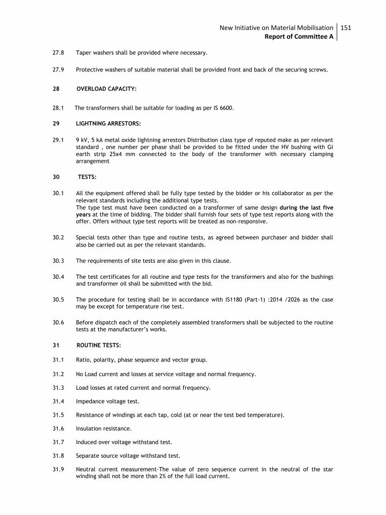
New Initiative on Material Mobilisation Report of Committee A
151
27.8 Taper washers shall be provided where necessary.
27.9 Protective washers of suitable material shall be provided front and back of the securing screws.
28 OVERLOAD CAPACITY:
28.1 The transformers shall be suitable for loading as per IS 6600.
29 LIGHTNING ARRESTORS:
29.1 9 kV, 5 kA metal oxide lightning arrestors Distribution class type of reputed make as per relevant
standard , one number per phase shall be provided to be fitted under the HV bushing with GI
earth strip 25x4 mm connected to the body of the transformer with necessary clamping
arrangement
30 TESTS:
30.1 All the equipment offered shall be fully type tested by the bidder or his collaborator as per the
relevant standards including the additional type tests. The type test must have been conducted on a transformer of same design during the last five years at the time of bidding. The bidder shall furnish four sets of type test reports along with the offer. Offers without type test reports will be treated as non-responsive.
30.2 Special tests other than type and routine tests, as agreed between purchaser and bidder shall
also be carried out as per the relevant standards.
30.3 The requirements of site tests are also given in this clause.
30.4 The test certificates for all routine and type tests for the transformers and also for the bushings and transformer oil shall be submitted with the bid.
30.5 The procedure for testing shall be in accordance with IS1180 (Part-1) :2014 /2026 as the case may be except for temperature rise test.
30.6 Before dispatch each of the completely assembled transformers shall be subjected to the routine tests at the manufacturer’s works.
31 ROUTINE TESTS:
31.1 Ratio, polarity, phase sequence and vector group.
31.2 No Load current and losses at service voltage and normal frequency.
31.3 Load losses at rated current and normal frequency.
31.4 Impedance voltage test.
31.5 Resistance of windings at each tap, cold (at or near the test bed temperature).
31.6 Insulation resistance.
31.7 Induced over voltage withstand test.
31.8 Separate source voltage withstand test.
31.9 Neutral current measurement-The value of zero sequence current in the neutral of the star
winding shall not be more than 2% of the full load current.
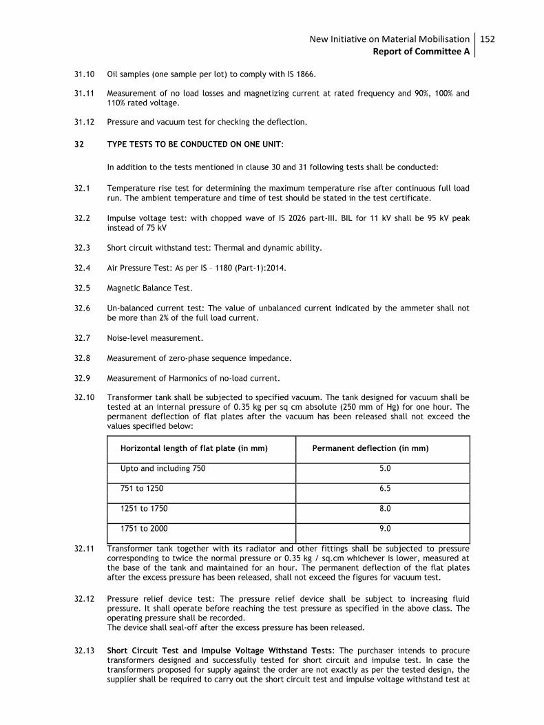
New Initiative on Material Mobilisation Report of Committee A
152
31.10 Oil samples (one sample per lot) to comply with IS 1866.
31.11 Measurement of no load losses and magnetizing current at rated frequency and 90%, 100% and
110% rated voltage.
31.12 Pressure and vacuum test for checking the deflection.
32 TYPE TESTS TO BE CONDUCTED ON ONE UNIT:
In addition to the tests mentioned in clause 30 and 31 following tests shall be conducted:
32.1 Temperature rise test for determining the maximum temperature rise after continuous full load
run. The ambient temperature and time of test should be stated in the test certificate.
32.2 Impulse voltage test: with chopped wave of IS 2026 part-III. BIL for 11 kV shall be 95 kV peak
instead of 75 kV
32.3 Short circuit withstand test: Thermal and dynamic ability.
32.4 Air Pressure Test: As per IS – 1180 (Part-1):2014.
32.5 Magnetic Balance Test.
32.6 Un-balanced current test: The value of unbalanced current indicated by the ammeter shall not
be more than 2% of the full load current.
32.7 Noise-level measurement.
32.8 Measurement of zero-phase sequence impedance.
32.9 Measurement of Harmonics of no-load current.
32.10 Transformer tank shall be subjected to specified vacuum. The tank designed for vacuum shall be
tested at an internal pressure of 0.35 kg per sq cm absolute (250 mm of Hg) for one hour. The permanent deflection of flat plates after the vacuum has been released shall not exceed the values specified below:
Horizontal length of flat plate (in mm) Permanent deflection (in mm)
Upto and including 750 5.0
751 to 1250 6.5
1251 to 1750 8.0
1751 to 2000 9.0
32.11 Transformer tank together with its radiator and other fittings shall be subjected to pressure corresponding to twice the normal pressure or 0.35 kg / sq.cm whichever is lower, measured at the base of the tank and maintained for an hour. The permanent deflection of the flat plates after the excess pressure has been released, shall not exceed the figures for vacuum test.
32.12 Pressure relief device test: The pressure relief device shall be subject to increasing fluid
pressure. It shall operate before reaching the test pressure as specified in the above class. The operating pressure shall be recorded.
The device shall seal-off after the excess pressure has been released.
32.13 Short Circuit Test and Impulse Voltage Withstand Tests: The purchaser intends to procure transformers designed and successfully tested for short circuit and impulse test. In case the transformers proposed for supply against the order are not exactly as per the tested design, the supplier shall be required to carry out the short circuit test and impulse voltage withstand test at
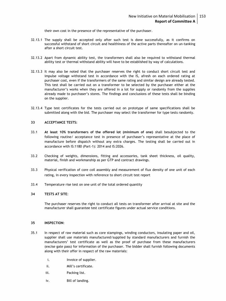
New Initiative on Material Mobilisation Report of Committee A
153
their own cost in the presence of the representative of the purchaser.
32.13.1 The supply shall be accepted only after such test is done successfully, as it confirms on
successful withstand of short circuit and healthiness of the active parts thereafter on un-tanking
after a short circuit test.
32.13.2 Apart from dynamic ability test, the transformers shall also be required to withstand thermal
ability test or thermal withstand ability will have to be established by way of calculations.
32.13.3 It may also be noted that the purchaser reserves the right to conduct short circuit test and
impulse voltage withstand test in accordance with the IS, afresh on each ordered rating at
purchaser cost, even if the transformers of the same rating and similar design are already tested.
This test shall be carried out on a transformer to be selected by the purchaser either at the
manufacturer’s works when they are offered in a lot for supply or randomly from the supplies
already made to purchaser’s stores. The findings and conclusions of these tests shall be binding
on the supplier.
32.13.4 Type test certificates for the tests carried out on prototype of same specifications shall be
submitted along with the bid. The purchaser may select the transformer for type tests randomly.
33 ACCEPTANCE TESTS:
33.1 At least 10% transformers of the offered lot (minimum of one) shall besubjected to the
following routine/ acceptance test in presence of purchaser’s representative at the place of
manufacture before dispatch without any extra charges. The testing shall be carried out in
accordance with IS:1180 (Part-1): 2014 and IS:2026.
33.2 Checking of weights, dimensions, fitting and accessories, tank sheet thickness, oil quality,
material, finish and workmanship as per GTP and contract drawings.
33.3 Physical verification of core coil assembly and measurement of flux density of one unit of each
rating, in every inspection with reference to short circuit test report
33.4 Temperature rise test on one unit of the total ordered quantity
34 TESTS AT SITE:
The purchaser reserves the right to conduct all tests on transformer after arrival at site and the
manufacturer shall guarantee test certificate figures under actual service conditions.
35 INSPECTION:
35.1 In respect of raw material such as core stampings, winding conductors, insulating paper and oil,
supplier shall use materials manufactured/supplied by standard manufacturers and furnish the
manufacturers’ test certificate as well as the proof of purchase from these manufacturers
(excise gate pass) for information of the purchaser. The bidder shall furnish following documents
along with their offer in respect of the raw materials:
i. Invoice of supplier.
ii. Mill’s certificate.
iii. Packing list.
iv. Bill of landing.
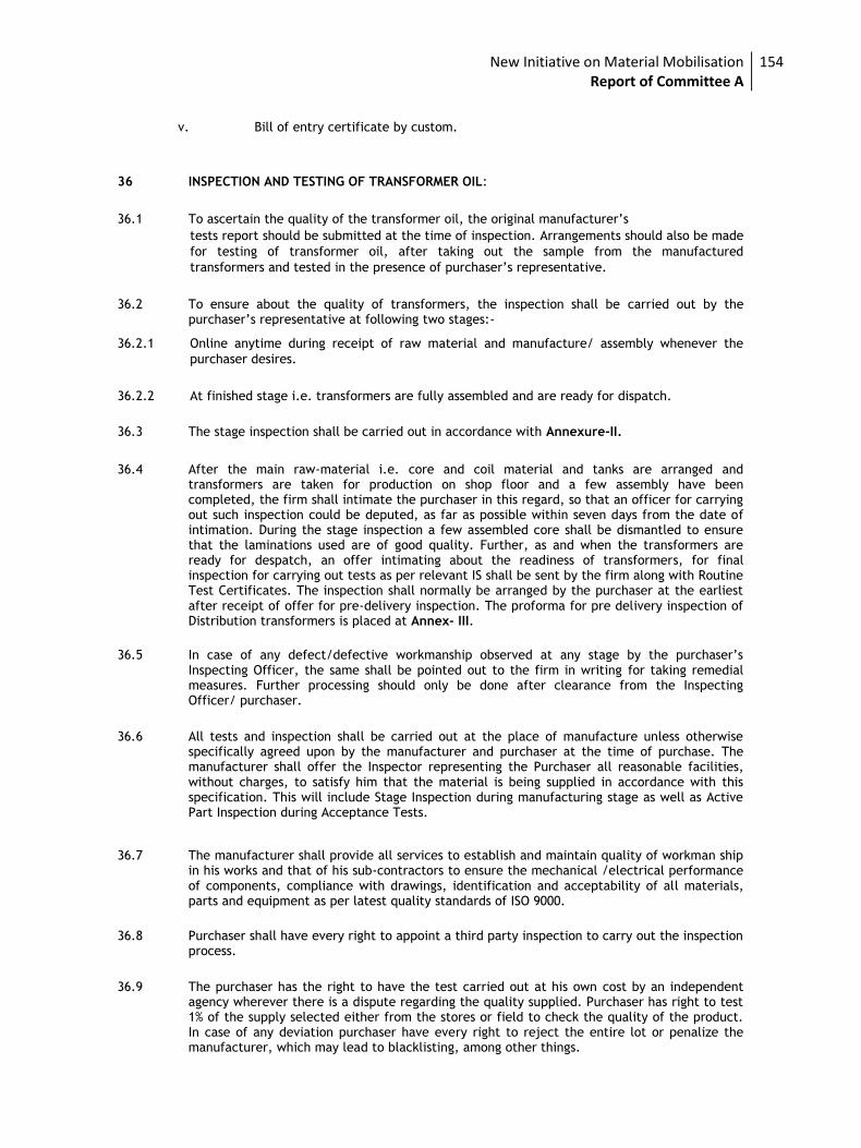
New Initiative on Material Mobilisation Report of Committee A
154
v. Bill of entry certificate by custom. 36 INSPECTION AND TESTING OF TRANSFORMER OIL:
36.1 To ascertain the quality of the transformer oil, the original manufacturer’s tests report should be submitted at the time of inspection. Arrangements should also be made
for testing of transformer oil, after taking out the sample from the manufactured
transformers and tested in the presence of purchaser’s representative.
36.2 To ensure about the quality of transformers, the inspection shall be carried out by the purchaser’s representative at following two stages:-
36.2.1 Online anytime during receipt of raw material and manufacture/ assembly whenever the
purchaser desires.
36.2.2 At finished stage i.e. transformers are fully assembled and are ready for dispatch.
36.3 The stage inspection shall be carried out in accordance with Annexure-II.
36.4 After the main raw-material i.e. core and coil material and tanks are arranged and transformers are taken for production on shop floor and a few assembly have been completed, the firm shall intimate the purchaser in this regard, so that an officer for carrying out such inspection could be deputed, as far as possible within seven days from the date of intimation. During the stage inspection a few assembled core shall be dismantled to ensure that the laminations used are of good quality. Further, as and when the transformers are ready for despatch, an offer intimating about the readiness of transformers, for final inspection for carrying out tests as per relevant IS shall be sent by the firm along with Routine Test Certificates. The inspection shall normally be arranged by the purchaser at the earliest after receipt of offer for pre-delivery inspection. The proforma for pre delivery inspection of Distribution transformers is placed at Annex- III.
36.5 In case of any defect/defective workmanship observed at any stage by the purchaser’s
Inspecting Officer, the same shall be pointed out to the firm in writing for taking remedial measures. Further processing should only be done after clearance from the Inspecting Officer/ purchaser.
36.6 All tests and inspection shall be carried out at the place of manufacture unless otherwise specifically agreed upon by the manufacturer and purchaser at the time of purchase. The manufacturer shall offer the Inspector representing the Purchaser all reasonable facilities, without charges, to satisfy him that the material is being supplied in accordance with this specification. This will include Stage Inspection during manufacturing stage as well as Active Part Inspection during Acceptance Tests.
36.7 The manufacturer shall provide all services to establish and maintain quality of workman ship in his works and that of his sub-contractors to ensure the mechanical /electrical performance of components, compliance with drawings, identification and acceptability of all materials, parts and equipment as per latest quality standards of ISO 9000.
36.8 Purchaser shall have every right to appoint a third party inspection to carry out the inspection process.
36.9 The purchaser has the right to have the test carried out at his own cost by an independent agency wherever there is a dispute regarding the quality supplied. Purchaser has right to test 1% of the supply selected either from the stores or field to check the quality of the product. In case of any deviation purchaser have every right to reject the entire lot or penalize the manufacturer, which may lead to blacklisting, among other things.
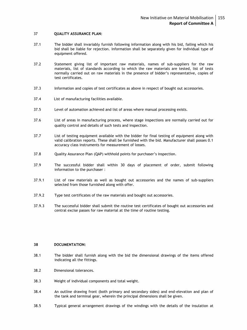
New Initiative on Material Mobilisation Report of Committee A
155
37 QUALITY ASSURANCE PLAN:
37.1 The bidder shall invariably furnish following information along with his bid, failing which his
bid shall be liable for rejection. Information shall be separately given for individual type of
equipment offered.
37.2 Statement giving list of important raw materials, names of sub-suppliers for the raw
materials, list of standards according to which the raw materials are tested, list of tests
normally carried out on raw materials in the presence of bidder’s representative, copies of
test certificates.
37.3 Information and copies of test certificates as above in respect of bought out accessories.
37.4 List of manufacturing facilities available.
37.5 Level of automation achieved and list of areas where manual processing exists.
37.6 List of areas in manufacturing process, where stage inspections are normally carried out for
quality control and details of such tests and inspection.
37.7 List of testing equipment available with the bidder for final testing of equipment along with
valid calibration reports. These shall be furnished with the bid. Manufacturer shall posses 0.1
accuracy class instruments for measurement of losses.
37.8 Quality Assurance Plan (QAP) withhold points for purchaser’s inspection.
37.9 The successful bidder shall within 30 days of placement of order, submit following
information to the purchaser :
37.9.1 List of raw materials as well as bought out accessories and the names of sub-suppliers
selected from those furnished along with offer.
37.9.2 Type test certificates of the raw materials and bought out accessories.
37.9.3 The successful bidder shall submit the routine test certificates of bought out accessories and
central excise passes for raw material at the time of routine testing.
38 DOCUMENTATION:
38.1 The bidder shall furnish along with the bid the dimensional drawings of the items offered
indicating all the fittings.
38.2 Dimensional tolerances.
38.3 Weight of individual components and total weight.
38.4 An outline drawing front (both primary and secondary sides) and end-elevation and plan of
the tank and terminal gear, wherein the principal dimensions shall be given.
38.5 Typical general arrangement drawings of the windings with the details of the insulation at
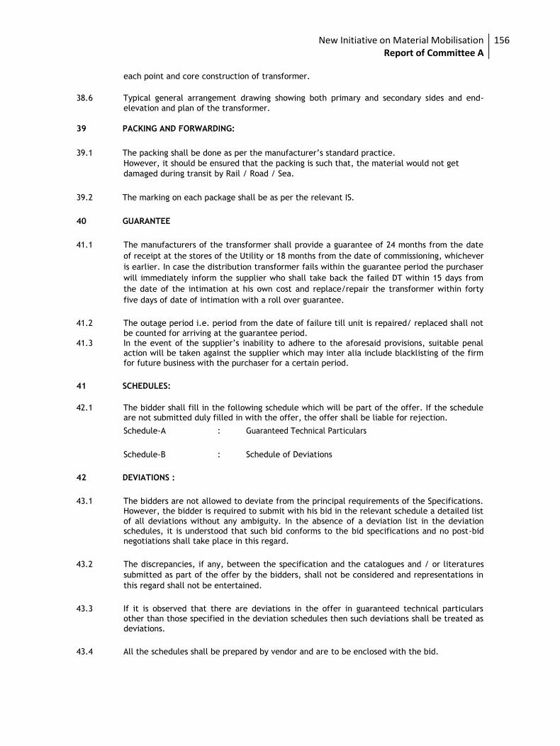
New Initiative on Material Mobilisation Report of Committee A
156
each point and core construction of transformer.
38.6 Typical general arrangement drawing showing both primary and secondary sides and end-
elevation and plan of the transformer.
39 PACKING AND FORWARDING:
39.1 The packing shall be done as per the manufacturer’s standard practice. However, it should be ensured that the packing is such that, the material would not get
damaged during transit by Rail / Road / Sea.
39.2 The marking on each package shall be as per the relevant IS.
40 GUARANTEE
41.1 The manufacturers of the transformer shall provide a guarantee of 24 months from the date
of receipt at the stores of the Utility or 18 months from the date of commissioning, whichever
is earlier. In case the distribution transformer fails within the guarantee period the purchaser
will immediately inform the supplier who shall take back the failed DT within 15 days from
the date of the intimation at his own cost and replace/repair the transformer within forty
five days of date of intimation with a roll over guarantee.
41.2 The outage period i.e. period from the date of failure till unit is repaired/ replaced shall not
be counted for arriving at the guarantee period. 41.3 In the event of the supplier’s inability to adhere to the aforesaid provisions, suitable penal
action will be taken against the supplier which may inter alia include blacklisting of the firm for future business with the purchaser for a certain period.
41 SCHEDULES:
42.1 The bidder shall fill in the following schedule which will be part of the offer. If the schedule
are not submitted duly filled in with the offer, the offer shall be liable for rejection.
Schedule-A : Guaranteed Technical Particulars
Schedule-B : Schedule of Deviations
42 DEVIATIONS :
43.1 The bidders are not allowed to deviate from the principal requirements of the Specifications. However, the bidder is required to submit with his bid in the relevant schedule a detailed list
of all deviations without any ambiguity. In the absence of a deviation list in the deviation schedules, it is understood that such bid conforms to the bid specifications and no post-bid negotiations shall take place in this regard.
43.2 The discrepancies, if any, between the specification and the catalogues and / or literatures
submitted as part of the offer by the bidders, shall not be considered and representations in
this regard shall not be entertained.
43.3 If it is observed that there are deviations in the offer in guaranteed technical particulars other than those specified in the deviation schedules then such deviations shall be treated as
deviations.
43.4 All the schedules shall be prepared by vendor and are to be enclosed with the bid.
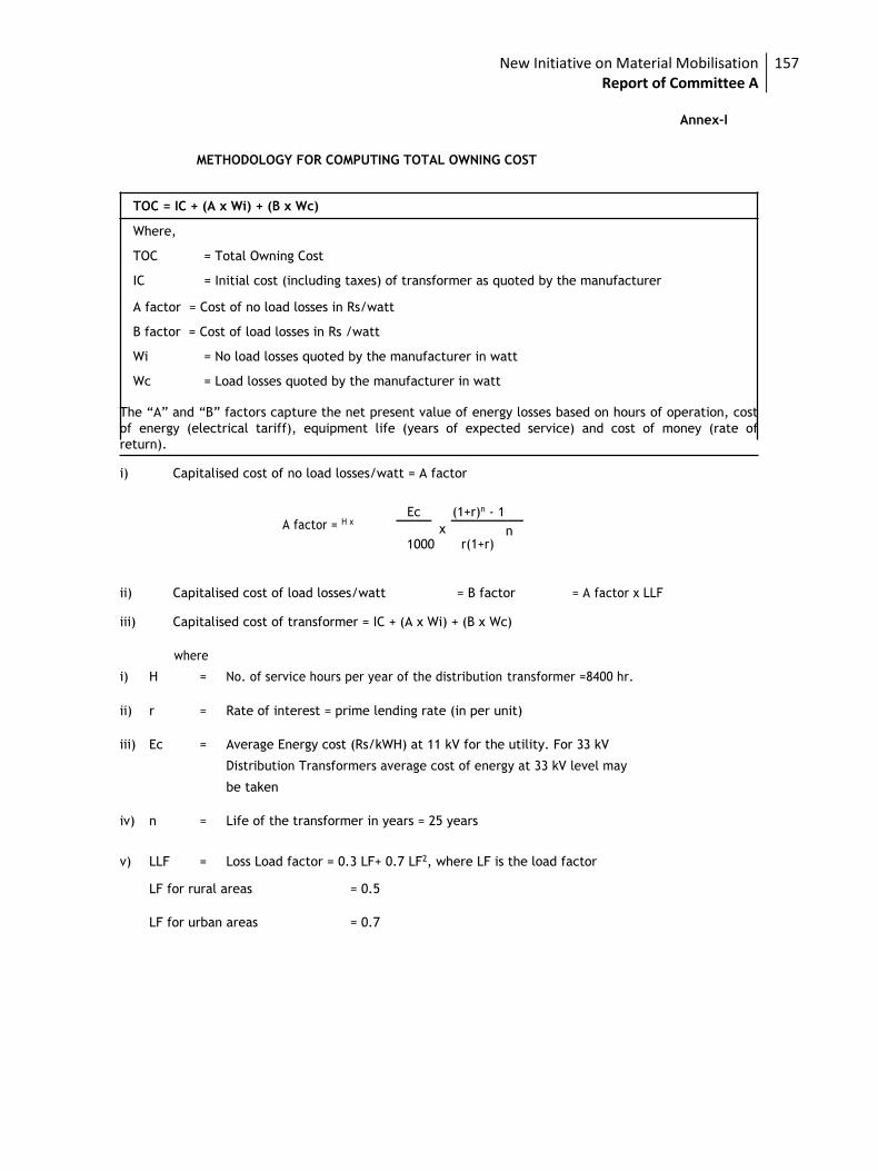
New Initiative on Material Mobilisation Report of Committee A
157
Annex-I
METHODOLOGY FOR COMPUTING TOTAL OWNING COST
TOC = IC + (A x Wi) + (B x Wc)
Where,
TOC = Total Owning Cost
IC = Initial cost (including taxes) of transformer as quoted by the manufacturer
A factor = Cost of no load losses in Rs/watt
B factor = Cost of load losses in Rs /watt
Wi = No load losses quoted by the manufacturer in watt
Wc = Load losses quoted by the manufacturer in watt
The “A” and “B” factors capture the net present value of energy losses based on hours of operation, cost
of energy (electrical tariff), equipment life (years of expected service) and cost of money (rate of
return). i) Capitalised cost of no load losses/watt = A factor
A factor = H x
Ec
x
(1+r)n - 1
1000 r(1+r)
n
ii) Capitalised cost of load losses/watt = B factor = A factor x LLF iii) Capitalised cost of transformer = IC + (A x Wi) + (B x Wc)
where
i) H = No. of service hours per year of the distribution transformer =8400 hr.
ii) r = Rate of interest = prime lending rate (in per unit)
iii) Ec = Average Energy cost (Rs/kWH) at 11 kV for the utility. For 33 kV
Distribution Transformers average cost of energy at 33 kV level may
be taken
iv) n = Life of the transformer in years = 25 years
v) LLF = Loss Load factor = 0.3 LF+ 0.7 LF2, where LF is the load factor
LF for rural areas = 0.5
LF for urban areas = 0.7
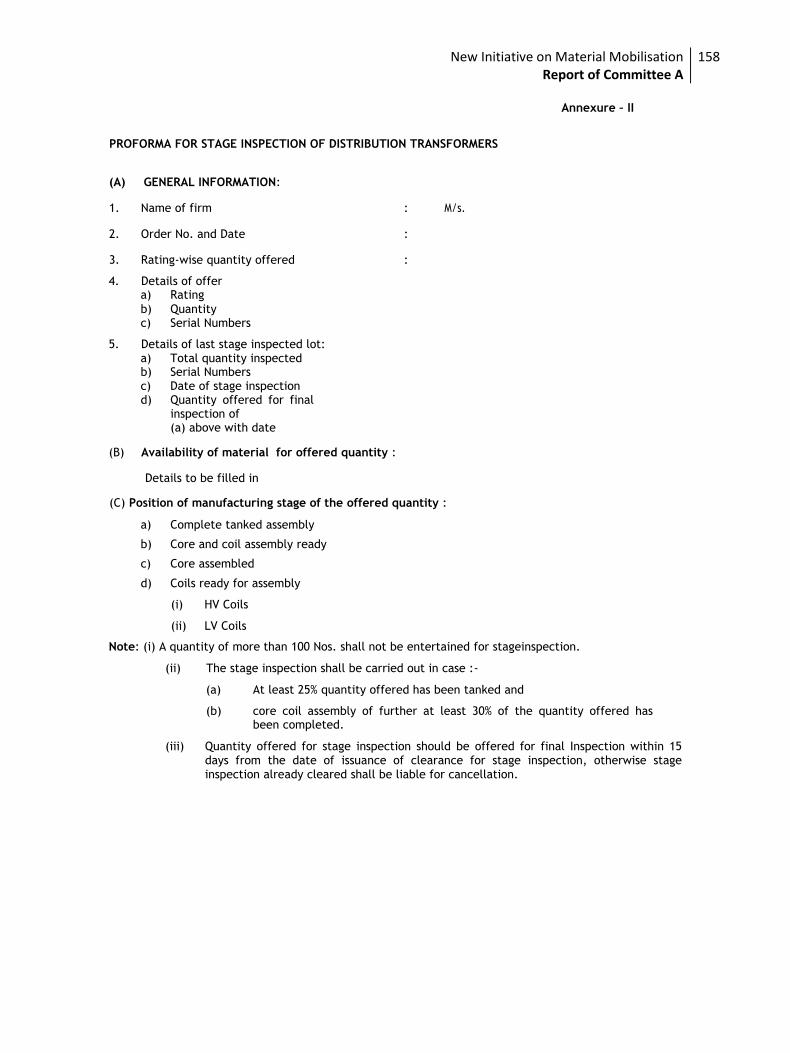
New Initiative on Material Mobilisation Report of Committee A
158
Annexure – II
PROFORMA FOR STAGE INSPECTION OF DISTRIBUTION TRANSFORMERS
(A) GENERAL INFORMATION:
1. Name of firm : M/s.
2. Order No. and Date :
3. Rating-wise quantity offered : 4. Details of offer
a) Rating b) Quantity c) Serial Numbers
5. Details of last stage inspected lot:
a) Total quantity inspected b) Serial Numbers c) Date of stage inspection d) Quantity offered for final
inspection of (a) above with date
(B) Availability of material for offered quantity :
Details to be filled in (C) Position of manufacturing stage of the offered quantity :
a) Complete tanked assembly
b) Core and coil assembly ready
c) Core assembled
d) Coils ready for assembly
(i) HV Coils
(ii) LV Coils Note: (i) A quantity of more than 100 Nos. shall not be entertained for stageinspection.
(ii) The stage inspection shall be carried out in case :-
(a) At least 25% quantity offered has been tanked and
(b) core coil assembly of further at least 30% of the quantity offered has been completed.
(iii) Quantity offered for stage inspection should be offered for final Inspection within 15
days from the date of issuance of clearance for stage inspection, otherwise stage inspection already cleared shall be liable for cancellation.
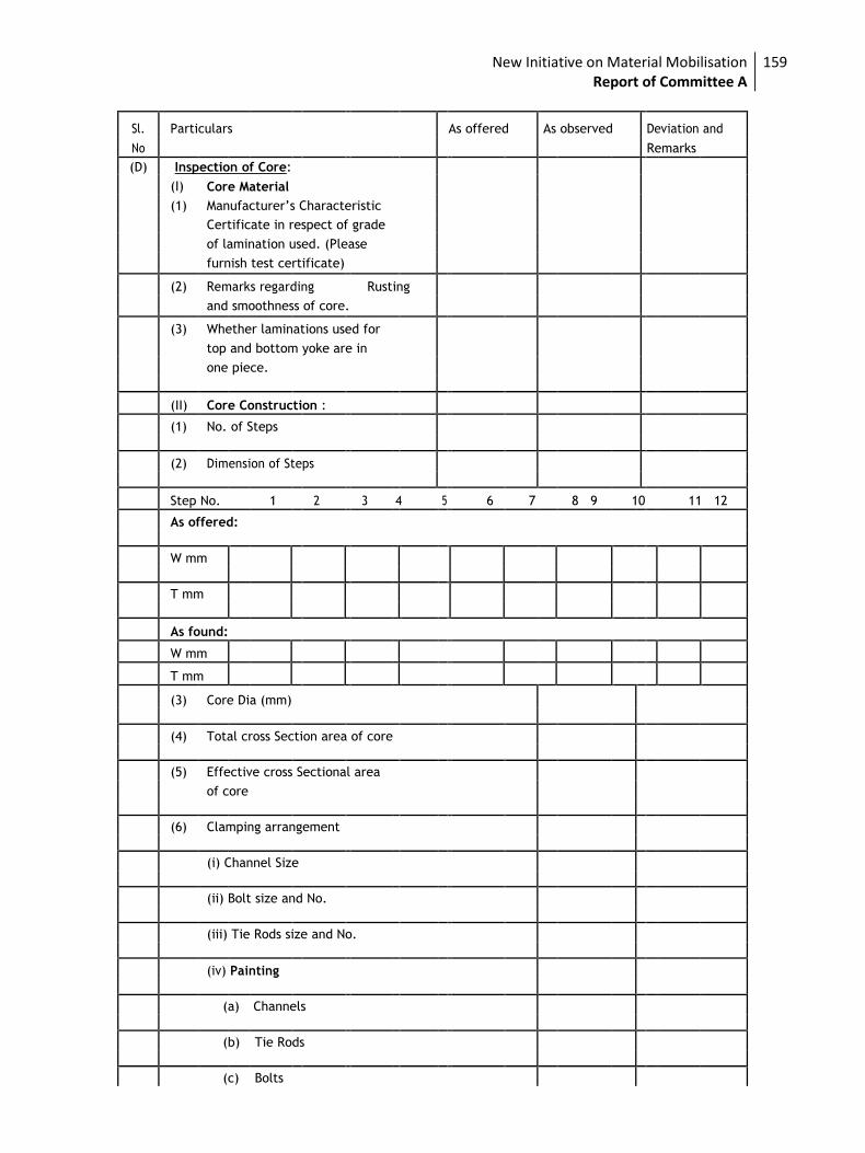
New Initiative on Material Mobilisation Report of Committee A
159
Sl. Particulars As offered As observed Deviation and
No Remarks
(D) Inspection of Core:
(I) Core Material
(1) Manufacturer’s Characteristic
Certificate in respect of grade
of lamination used. (Please
furnish test certificate)
(2) Remarks regarding Rusting
and smoothness of core.
(3) Whether laminations used for
top and bottom yoke are in
one piece.
(II) Core Construction :
(1) No. of Steps
(2) Dimension of Steps
Step No. 1 2 3 4 5 6 7 8 9 10 11 12
As offered:
W mm
T mm
As found:
W mm
T mm
(3) Core Dia (mm)
(4) Total cross Section area of core
(5) Effective cross Sectional area
of core
(6) Clamping arrangement
(i) Channel Size
(ii) Bolt size and No.
(iii) Tie Rods size and No.
(iv) Painting
(a) Channels
(b) Tie Rods
(c) Bolts
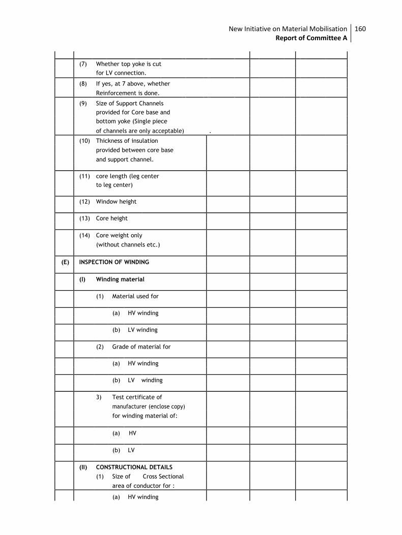
New Initiative on Material Mobilisation Report of Committee A
160
(7) Whether top yoke is cut
for LV connection.
(8) If yes, at 7 above, whether
Reinforcement is done.
(9) Size of Support Channels
provided for Core base and
bottom yoke (Single piece
of channels are only acceptable) .
(10) Thickness of insulation
provided between core base
and support channel.
(11) core length (leg center
to leg center)
(12) Window height
(13) Core height
(14) Core weight only
(without channels etc.)
(E) INSPECTION OF WINDING
(I) Winding material
(1) Material used for
(a) HV winding
(b) LV winding
(2) Grade of material for
(a) HV winding
(b) LV winding
3) Test certificate of
manufacturer (enclose copy)
for winding material of:
(a) HV
(b) LV
(II) CONSTRUCTIONAL DETAILS
(1) Size of Cross Sectional
area of conductor for :
(a) HV winding
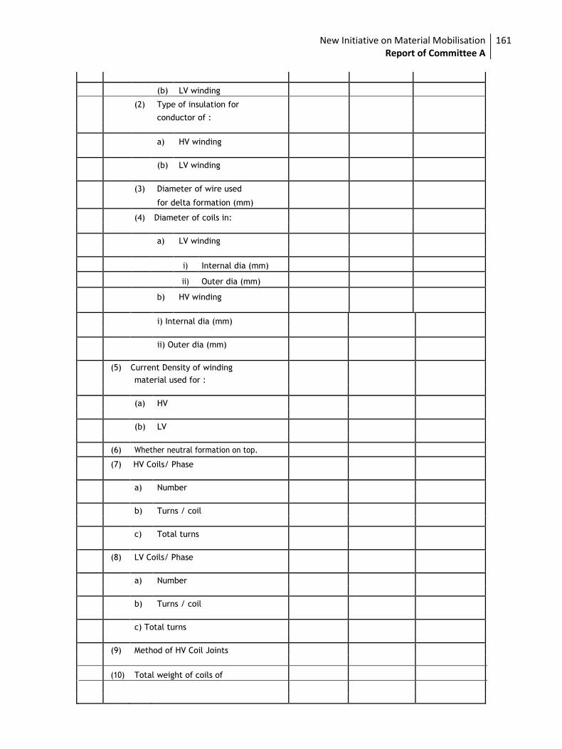
New Initiative on Material Mobilisation Report of Committee A
161
(b) LV winding
(2) Type of insulation for
conductor of :
a) HV winding
(b) LV winding
(3) Diameter of wire used
for delta formation (mm)
(4) Diameter of coils in:
a) LV winding
i) Internal dia (mm)
ii) Outer dia (mm)
b) HV winding
i) Internal dia (mm)
ii) Outer dia (mm)
(5) Current Density of winding
material used for :
(a) HV
(b) LV
(6) Whether neutral formation on top.
(7) HV Coils/ Phase
a) Number
b) Turns / coil
c) Total turns
(8) LV Coils/ Phase
a) Number
b) Turns / coil
c) Total turns
(9) Method of HV Coil Joints
(10) Total weight of coils of
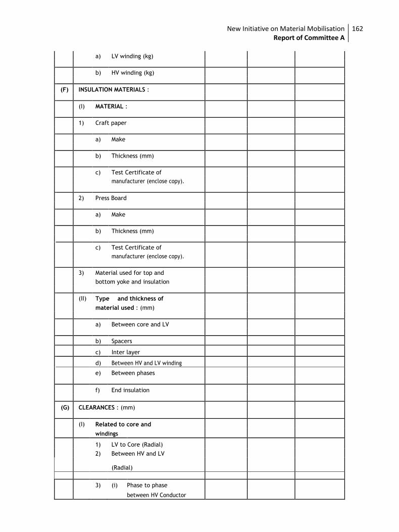
New Initiative on Material Mobilisation Report of Committee A
162
a) LV winding (kg)
b) HV winding (kg)
(F) INSULATION MATERIALS :
(I) MATERIAL :
1) Craft paper
a) Make
b) Thickness (mm)
c) Test Certificate of
manufacturer (enclose copy).
2) Press Board
a) Make
b) Thickness (mm)
c) Test Certificate of
manufacturer (enclose copy).
3) Material used for top and
bottom yoke and insulation
(II) Type and thickness of
material used : (mm)
a) Between core and LV
b) Spacers
c) Inter layer
d) Between HV and LV winding
e) Between phases
f) End insulation
(G) CLEARANCES : (mm)
(I) Related to core and
windings
1) LV to Core (Radial)
2) Between HV and LV
(Radial)
3) (i) Phase to phase
between HV Conductor
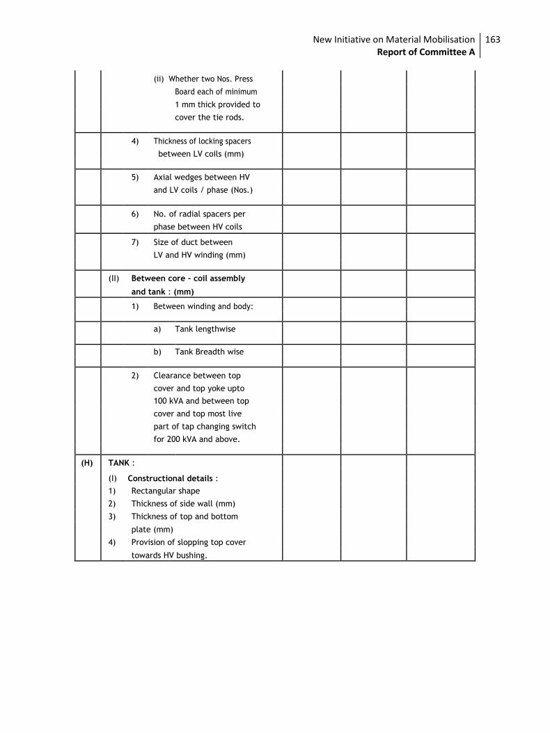
New Initiative on Material Mobilisation Report of Committee A
163
(ii) Whether two Nos. Press
Board each of minimum
1 mm thick provided to
cover the tie rods.
4) Thickness of locking spacers
between LV coils (mm)
5) Axial wedges between HV
and LV coils / phase (Nos.)
6) No. of radial spacers per
phase between HV coils
7) Size of duct between
LV and HV winding (mm)
(II) Between core - coil assembly
and tank : (mm)
1) Between winding and body:
a) Tank lengthwise
b) Tank Breadth wise
2) Clearance between top
cover and top yoke upto
100 kVA and between top
cover and top most live
part of tap changing switch
for 200 kVA and above.
(H) TANK :
(I) Constructional details :
1) Rectangular shape
2) Thickness of side wall (mm)
3) Thickness of top and bottom
plate (mm)
4) Provision of slopping top cover
towards HV bushing.
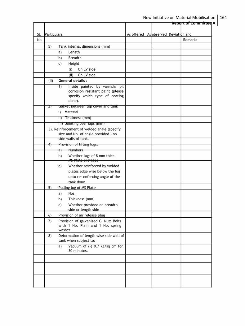
New Initiative on Material Mobilisation Report of Committee A
164
Sl. Particulars As offered As observed Deviation and
No Remarks
5) Tank internal dimensions (mm)
a) Length
b) Breadth
c) Height
(i) On LV side
(ii) On LV side
(II) General details :
1) Inside painted by varnish/ oil
corrosion resistant paint (please
specify which type of coating
done).
2) Gasket between top cover and tank
i) Material
ii) Thickness (mm)
iii) Jointing over laps (mm)
3). Reinforcement of welded angle (specify
size and No. of angle provided ) on
side walls of tank.
4) Provision of lifting lugs:
a) Numbers
b) Whether lugs of 8 mm thick
MS Plate provided
c) Whether reinforced by welded
plates edge wise below the lug
upto re- enforcing angle of the
tank done.
5) Pulling lug of MS Plate
a) Nos.
b) Thickness (mm)
c) Whether provided on breadth
side or length side
6) Provision of air release plug
7) Provision of galvanized GI Nuts Bolts
with 1 No. Plain and 1 No. spring
washer.
8) Deformation of length wise side wall of
tank when subject to:
a) Vacuum of (-) 0.7 kg/sq cm for
30 minutes.
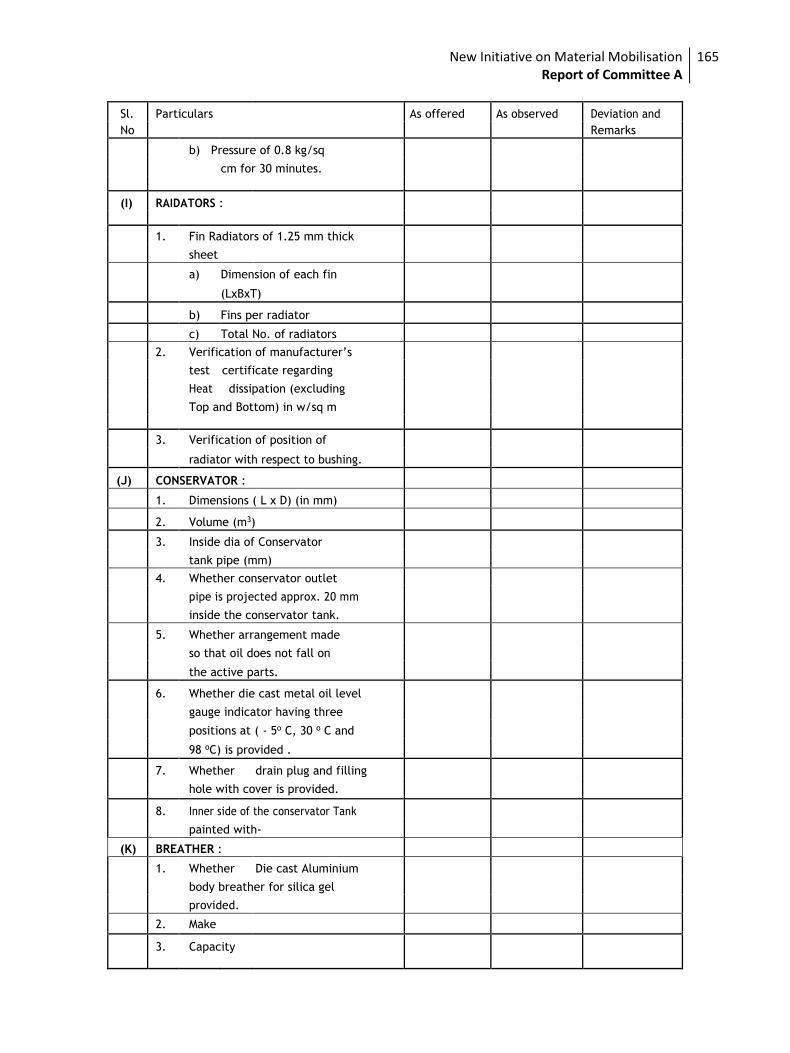
New Initiative on Material Mobilisation Report of Committee A
165
Sl. Particulars As offered As observed Deviation and
No Remarks
b) Pressure of 0.8 kg/sq
cm for 30 minutes.
(I) RAIDATORS :
1. Fin Radiators of 1.25 mm thick
sheet
a) Dimension of each fin
(LxBxT)
b) Fins per radiator
c) Total No. of radiators
2. Verification of manufacturer’s
test certificate regarding
Heat dissipation (excluding
Top and Bottom) in w/sq m
3. Verification of position of
radiator with respect to bushing.
(J) CONSERVATOR :
1. Dimensions ( L x D) (in mm)
2. Volume (m3)
3. Inside dia of Conservator
tank pipe (mm)
4. Whether conservator outlet
pipe is projected approx. 20 mm
inside the conservator tank.
5. Whether arrangement made
so that oil does not fall on
the active parts.
6. Whether die cast metal oil level
gauge indicator having three
positions at ( - 5o C, 30 o C and
98 oC) is provided .
7. Whether drain plug and filling
hole with cover is provided.
8. Inner side of the conservator Tank
painted with-
(K) BREATHER :
1. Whether Die cast Aluminium
body breather for silica gel
provided.
2. Make
3. Capacity
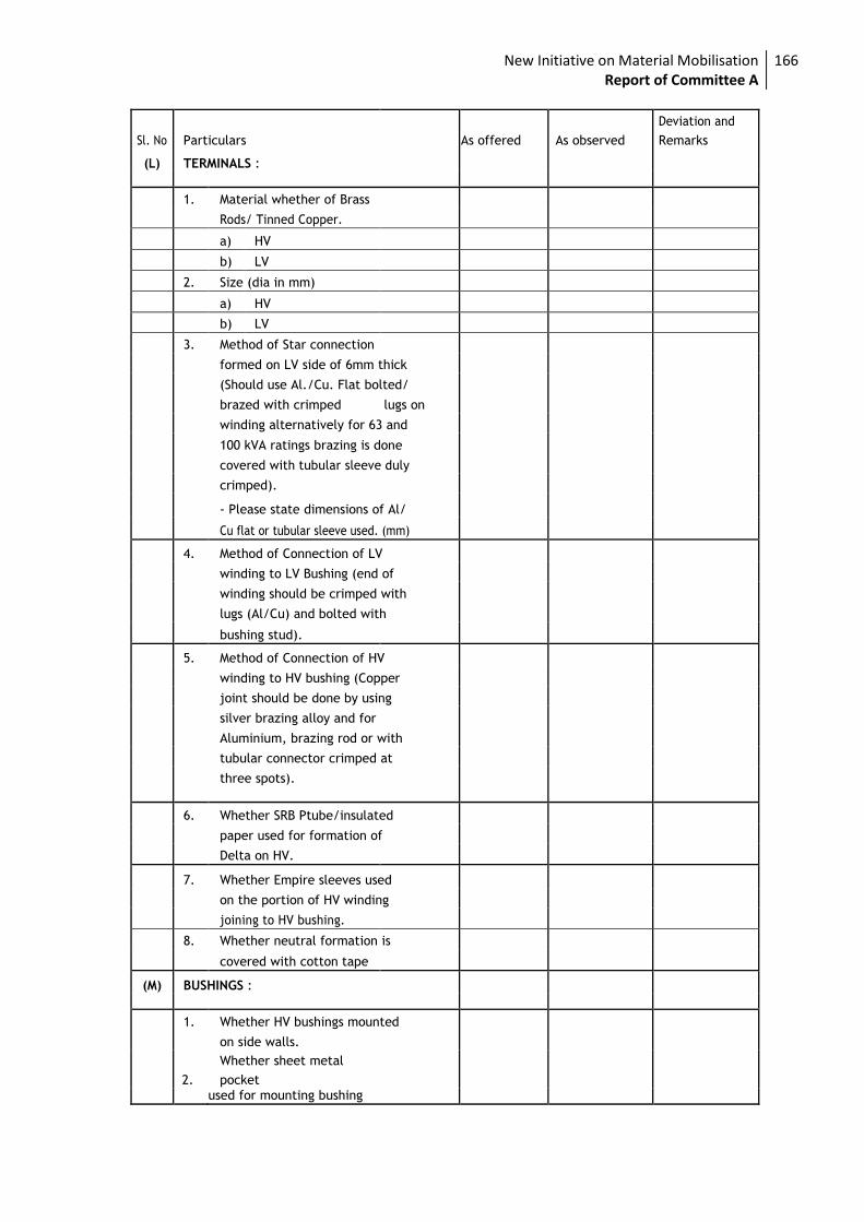
New Initiative on Material Mobilisation Report of Committee A
166
Sl. No Particulars As offered As observed
Deviation and
Remarks
(L) TERMINALS :
1. Material whether of Brass
Rods/ Tinned Copper.
a) HV
b) LV
2. Size (dia in mm)
a) HV
b) LV
3. Method of Star connection
formed on LV side of 6mm thick
(Should use Al./Cu. Flat bolted/
brazed with crimped lugs on
winding alternatively for 63 and
100 kVA ratings brazing is done
covered with tubular sleeve duly
crimped).
- Please state dimensions of Al/
Cu flat or tubular sleeve used. (mm)
4. Method of Connection of LV
winding to LV Bushing (end of
winding should be crimped with
lugs (Al/Cu) and bolted with
bushing stud).
5. Method of Connection of HV
winding to HV bushing (Copper
joint should be done by using
silver brazing alloy and for
Aluminium, brazing rod or with
tubular connector crimped at
three spots).
6. Whether SRB Ptube/insulated
paper used for formation of
Delta on HV.
7. Whether Empire sleeves used
on the portion of HV winding
joining to HV bushing.
8. Whether neutral formation is
covered with cotton tape
(M) BUSHINGS :
1. Whether HV bushings mounted
on side walls.
2.
Whether sheet metal
pocket used for mounting bushing
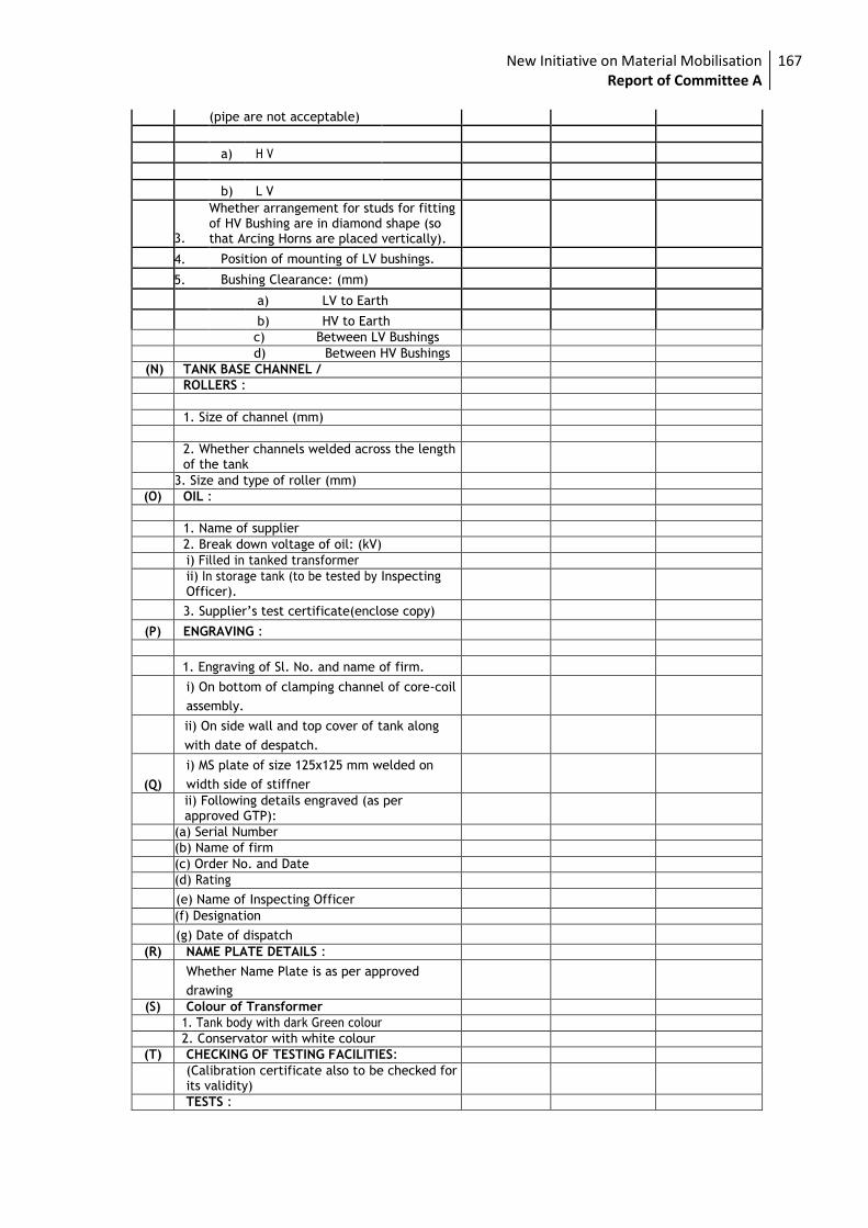
New Initiative on Material Mobilisation Report of Committee A
167
(pipe are not acceptable)
a) H V
b) L V
3.
Whether arrangement for studs for fitting of HV Bushing are in diamond shape (so that Arcing Horns are placed vertically).
4. Position of mounting of LV bushings.
5. Bushing Clearance: (mm)
a) LV to Earth
b) HV to Earth
c) Between LV Bushings
d) Between HV Bushings
(N) TANK BASE CHANNEL /
ROLLERS :
1. Size of channel (mm)
2. Whether channels welded across the length of the tank
3. Size and type of roller (mm)
(O) OIL :
1. Name of supplier
2. Break down voltage of oil: (kV)
i) Filled in tanked transformer
ii) In storage tank (to be tested by Inspecting Officer).
3. Supplier’s test certificate(enclose copy)
(P) ENGRAVING :
1. Engraving of Sl. No. and name of firm.
i) On bottom of clamping channel of core-coil
assembly.
ii) On side wall and top cover of tank along
with date of despatch.
(Q)
i) MS plate of size 125x125 mm welded on
width side of stiffner
ii) Following details engraved (as per approved GTP):
(a) Serial Number
(b) Name of firm
(c) Order No. and Date
(d) Rating
(e) Name of Inspecting Officer
(f) Designation
(g) Date of dispatch
(R) NAME PLATE DETAILS :
Whether Name Plate is as per approved
drawing
(S) Colour of Transformer
1. Tank body with dark Green colour
2. Conservator with white colour
(T) CHECKING OF TESTING FACILITIES:
(Calibration certificate also to be checked for its validity)
TESTS :
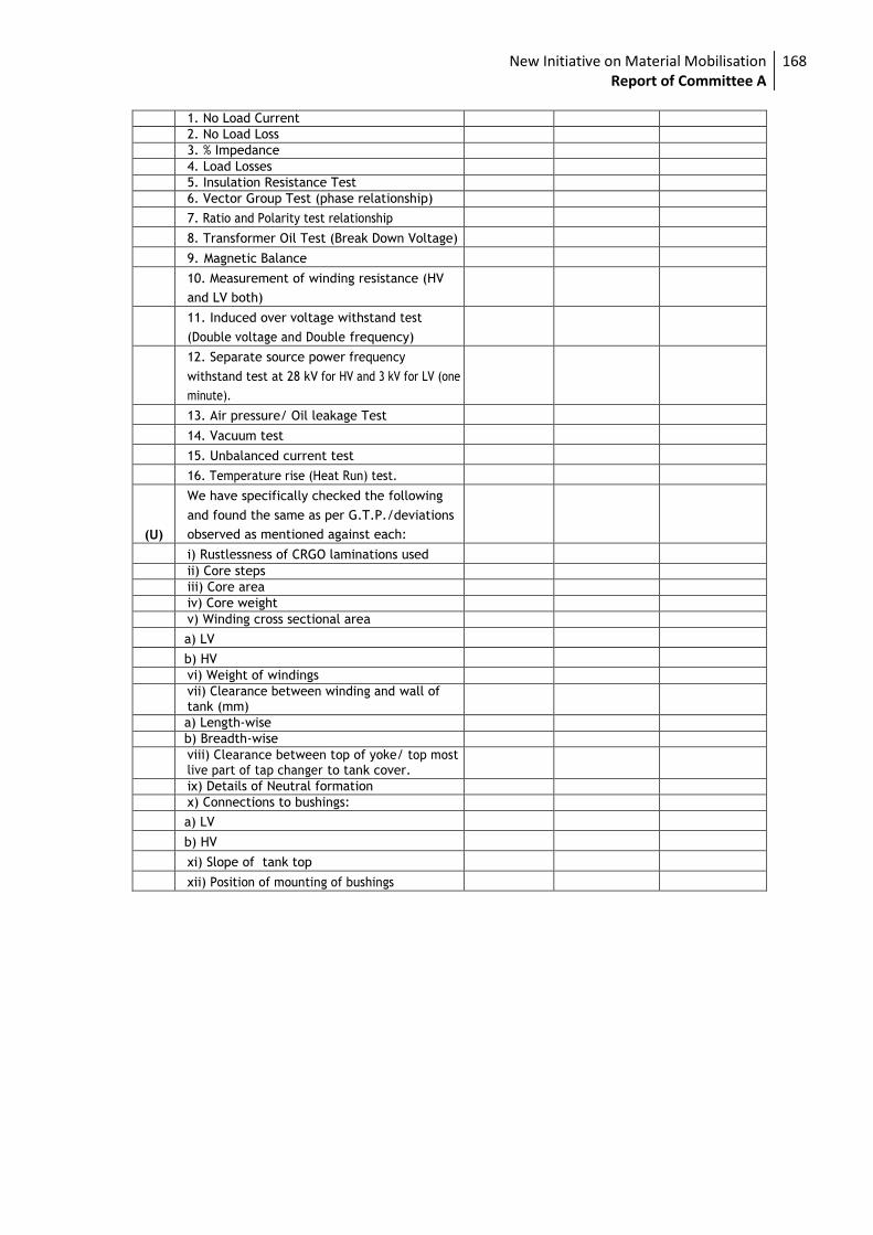
New Initiative on Material Mobilisation Report of Committee A
168
1. No Load Current
2. No Load Loss
3. % Impedance
4. Load Losses
5. Insulation Resistance Test
6. Vector Group Test (phase relationship)
7. Ratio and Polarity test relationship
8. Transformer Oil Test (Break Down Voltage)
9. Magnetic Balance
10. Measurement of winding resistance (HV
and LV both)
11. Induced over voltage withstand test
(Double voltage and Double frequency)
12. Separate source power frequency
withstand test at 28 kV for HV and 3 kV for LV (one
minute).
13. Air pressure/ Oil leakage Test
14. Vacuum test
15. Unbalanced current test
16. Temperature rise (Heat Run) test.
(U)
We have specifically checked the following
and found the same as per G.T.P./deviations
observed as mentioned against each:
i) Rustlessness of CRGO laminations used
ii) Core steps
iii) Core area
iv) Core weight
v) Winding cross sectional area
a) LV
b) HV
vi) Weight of windings
vii) Clearance between winding and wall of tank (mm)
a) Length-wise
b) Breadth-wise
viii) Clearance between top of yoke/ top most live part of tap changer to tank cover.
ix) Details of Neutral formation
x) Connections to bushings:
a) LV
b) HV
xi) Slope of tank top
xii) Position of mounting of bushings
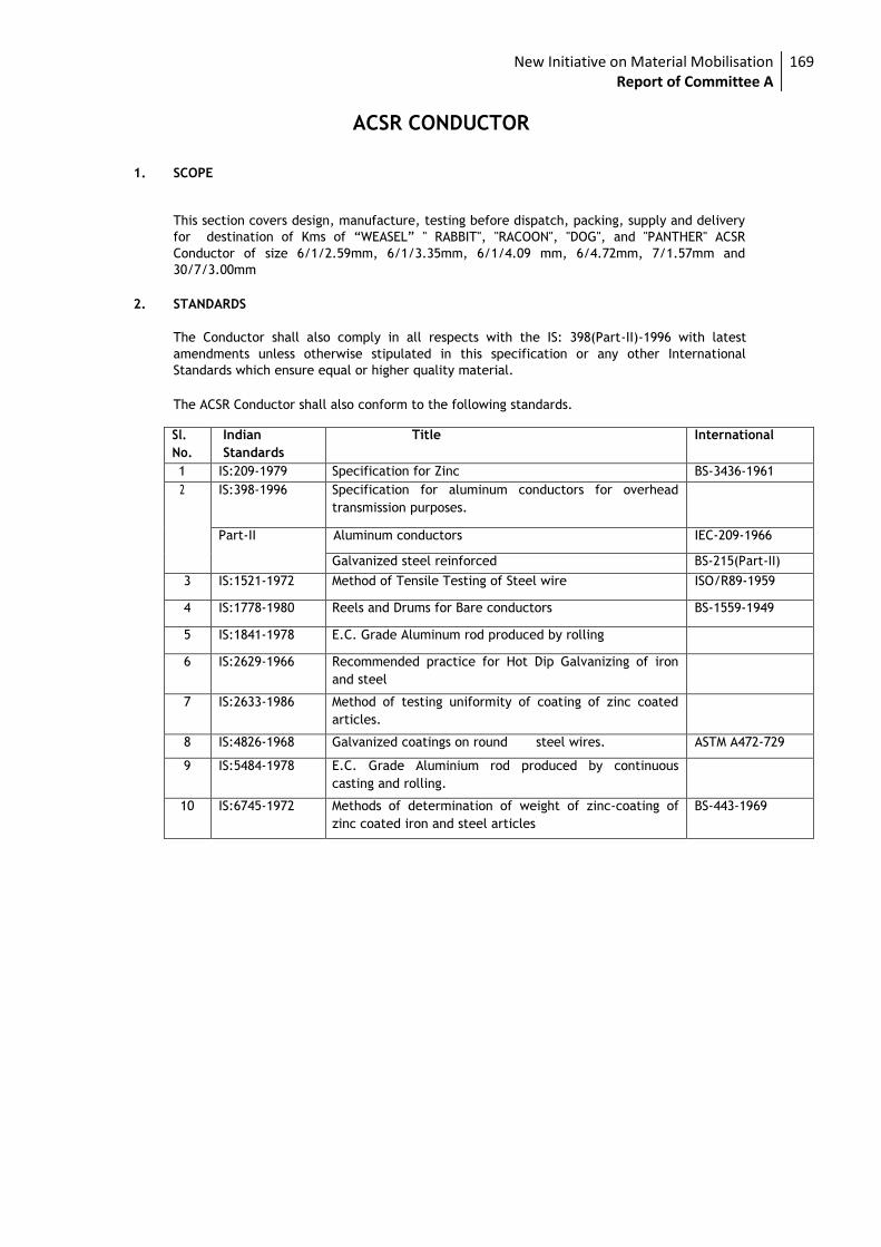
New Initiative on Material Mobilisation Report of Committee A
169
ACSR CONDUCTOR
1. SCOPE
This section covers design, manufacture, testing before dispatch, packing, supply and delivery
for destination of Kms of “WEASEL” " RABBIT", "RACOON", "DOG", and "PANTHER" ACSR
Conductor of size 6/1/2.59mm, 6/1/3.35mm, 6/1/4.09 mm, 6/4.72mm, 7/1.57mm and
30/7/3.00mm
2. STANDARDS
The Conductor shall also comply in all respects with the IS: 398(Part-II)-1996 with latest
amendments unless otherwise stipulated in this specification or any other International
Standards which ensure equal or higher quality material.
The ACSR Conductor shall also conform to the following standards.
Sl.
No.
Indian
Standards
Title International
1 IS:209-1979 Specification for Zinc BS-3436-1961
2 IS:398-1996 Specification for aluminum conductors for overhead
transmission purposes.
Part-II Aluminum conductors IEC-209-1966
Galvanized steel reinforced BS-215(Part-II)
3 IS:1521-1972 Method of Tensile Testing of Steel wire ISO/R89-1959
4 IS:1778-1980 Reels and Drums for Bare conductors BS-1559-1949
5 IS:1841-1978 E.C. Grade Aluminum rod produced by rolling
6 IS:2629-1966 Recommended practice for Hot Dip Galvanizing of iron
and steel
7 IS:2633-1986 Method of testing uniformity of coating of zinc coated
articles.
8 IS:4826-1968 Galvanized coatings on round steel wires. ASTM A472-729
9 IS:5484-1978 E.C. Grade Aluminium rod produced by continuous
casting and rolling.
10 IS:6745-1972 Methods of determination of weight of zinc-coating of
zinc coated iron and steel articles
BS-443-1969
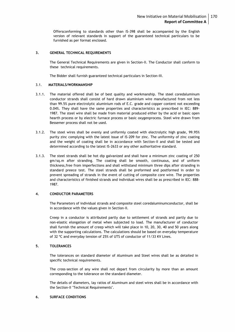
New Initiative on Material Mobilisation Report of Committee A
170
Offersconforming to standards other than IS-398 shall be accompanied by the English
version of relevant standards in support of the guaranteed technical particulars to be
furnished as per format enclosed.
3. GENERAL TECHNICAL REQUIREMENTS
The General Technical Requirements are given in Section-II. The Conductor shall conform to
these technical requirements.
The Bidder shall furnish guaranteed technical particulars in Section-III.
3.1. MATERIALS/WORKMANSHIP
3.1.1. The material offered shall be of best quality and workmanship. The steel coredaluminum
conductor strands shall consist of hard drawn aluminium wire manufactured from not less
than 99.5% pure electrolytic aluminium rods of E.C. grade and copper content not exceeding
0.04%. They shall have the same properties and characteristics as prescribed in IEC: 889-
1987. The steel wire shall be made from material produced either by the acid or basic open
hearth process or by electric furnace process or basic oxygenprocess. Steel wire drawn from
Bessemer process shall not be used.
3.1.2. The steel wires shall be evenly and uniformly coated with electrolytic high grade, 99.95%
purity zinc complying with the latest issue of IS-209 for zinc. The uniformity of zinc coating
and the weight of coating shall be in accordance with Section-II and shall be tested and
determined according to the latest IS-2633 or any other authoritative standard.
3.1.3. The steel strands shall be hot dip galvanized and shall have a minimum zinc coating of 250
gm/sq.m after stranding. The coating shall be smooth, continuous, and of uniform
thickness,free from imperfections and shall withstand minimum three dips after stranding in
standard preece test. The steel strands shall be preformed and postformed in order to
prevent spreading of strands in the event of cutting of composite core wire. The properties
and characteristics of finished strands and individual wires shall be as prescribed in IEC: 888-
1987.
4. CONDUCTOR PARAMETERS
The Parameters of individual strands and composite steel coredaluminumconductor, shall be
in accordance with the values given in Section-II.
Creep in a conductor is attributed partly due to settlement of strands and partly due to
non-elastic elongation of metal when subjected to load. The manufacturer of conductor
shall furnish the amount of creep which will take place in 10, 20, 30, 40 and 50 years along
with the supporting calculations. The calculations should be based on everyday temperature
of 32 ºC and everyday tension of 25% of UTS of conductor of 11/33 KV Lines.
5. TOLERANCES
The tolerances on standard diameter of Aluminum and Steel wires shall be as detailed in
specific technical requirements.
The cross-section of any wire shall not depart from circularity by more than an amount
corresponding to the tolerance on the standard diameter.
The details of diameters, lay ratios of Aluminum and steel wires shall be in accordance with
the Section-II "Technical Requirements".
6. SURFACE CONDITIONS
New Initiative on Material Mobilisation Report of Committee A
171
All aluminum and steel strands shall be smooth, and free from all imperfections, spills/and
splits. The finished conductor shall be smooth, compact, uniform and free from all
imperfections including spills and splits, die marks, scratches, abrasions, scuff marks, kinks
(protrusion of wires), dents, pressmarks, cut marks, wire cross-over, over-riding looseness,
pressure and/or unusual bangle noise on tapping, material inclusions, white rust, powder
formation or black spots (on account of reaction with trapped rain water etc.,), dirt, grit,
etc. The surface of conductor shall be free from points, sharp edges, abrasions or other
departures from smoothness or uniformity of surface contour that would increase radio
interference and corona losses. When subjected to tension upto 50% of the ultimate
strength of the conductor, the surface shall not depart from the cylindrical form nor any
part of the component parts or strands move relative to each other in such a way as to get
out of place and disturb the longitudinal smoothness of the conductor.
7. JOINTS IN WIRES
7.1. Aluminum wires
During stranding, no aluminum wire welds shall be made for the purpose of achieving the
required conductor length.
No joint shall be permitted in the individual aluminum wires in the outer most layer of the
finished Conductor. However, joints in the 12 wire & 18 wire inner layer of the conductor
are permitted but these joints shall be made by the cold pressure butt welding and shall be
such that no two such joints shall be within 15 meters of each other in the complete
stranded conductor.
7.2. Steel wires
There shall be no joints in finished steel wires forming the core of the steel reinforced
aluminum conductor.
8. STRANDING
The wires used in construction of the stranded conductor, shall, before stranding, satisfy all
requirements of IS-398 (Part-II) 1996.
In all constructions, the successive layers shall be stranded in opposite directions. The wires
in each layer shall be evenly and closely stranded round the underlying wire or wires. The
outer most layer of wires shall have a right hand lay. The lay ratio of the different layers
shall be within the limits given under Section-II.
9. PACKING
9.1. The conductor shall be supplied in non-returnable strong wooden drums provided with
lagging of adequate strength constructed to protect the conductor against any damage and
displacement during transit, storage and subsequent handling and stringing operations in the
field. The drums shall generally conform to IS-1778-1980 and latest version except as
otherwise specified hereinafter. The conductor drums shall be adequate to wind one
standard length of 2500 meters of WEASEL/RABIT/RACOON/DOG/PANTHERACSR conductor.
9.2. The drums shall be suitable for wheel mounting and for letting off the conductor under a
minimum controlled tension of the order of 5KN. The conductor drums shall be provided with
necessary clamping arrangements so as to be suitable for tension stringing of power
conductor.
9.3. The bidders should submit their drawings of the conductor drums along with the bid. After
placement of letter of intent the Manufacturer shall submit four copies of fully dimensioned
New Initiative on Material Mobilisation Report of Committee A
172
drawing of the drum for Employer's approval. After getting approval from the Employer,
Manufacturer shall submit 30 more copies of the approved drawings for further distribution
and field use.
9.4. All wooden components shall be manufactured out of seasoned soft wood free from defects
that may materially weaken the component parts of the drums. Preservative treatment for
anti-termite/anti fungus shall be applied to the entire drum with preservatives of a quality
which is not harmful to the conductor.
9.5. All flanges shall be 2-ply construction with 64 mm thickness. Each ply shall be nailed and
clenched together at approximately 90 degrees. Nails shall be driven from the inside face of
the flange, punched and then clenched on the outer face. Flange boards shall not be less
than the nominal thickness by more than 2 mm. There shall not be less than 2 nails per board
in each circle.
9.6. The wooden battens used for making the barrel of the conductor shall be of segmental type.
These shall be nailed to the barrel supports with at least two nails. The battens shall be
closely butted and shall provide a round barrel with smooth external surface. The edges of
the battens shall be rounded or chamfered to avoid damage to the conductor.
9.7. Barrel studs shall be used for construction of drums. The flanges shall be holed and the
barrel supports slotted to receive them. The barrel studs shall be threaded over a length on
either end, sufficient to accommodate washers, spindle plates and nuts for fixing flanges at
the required spacing.
9.8. Normally, the nuts on the studs shall stand protruded of the flanges. All the nails used on the
inner surface of the flanges and the drum barrel shall be countersunk. The ends of the barrel
shall generally be flushed with the top of the nuts.
9.9. The inner cheek of the flanges and drum barrel surface shall be painted with bitumen based
paint.
9.10. Before reeling, card board or double corrugated or thick bituminized waterproof bamboo
paper shall be secured to the drum barrel and inside of flanges of the drum by means of a
suitable commercial adhesive material. The paper should be dried before use. Medium grade
craft paper shall be used in between the layers of the conductor. After reeling the conductor
the exposed surface of the outer layer of conductor shall be wrapped with thin polythene
sheet across the flanges to preserve the conductor from dirt, grit and damage during
transportation and handling and also to prevent ingress of rain water during
storage/transport.
9.11. A minimum space of 75 mm shall be provided between the inner surface of the external
protective lagging and outer layer of the conductor. Outside the protective lagging, there
shall be minimum of two binders consisting of hoop iron/galvanised steel wire. Each
protective lagging shall have two recesses to accommodate the binders.
9.12. Each batten shall be securely nailed across grains as far as possible to the flange edges with
at least 2 nails per end. The length of the nails shall not be less than twice the thickness of
the battens. The nail shall not protrude above the general surface and shall not have
exposed sharp edges or allow the battens to be released due to corrosion.
9.13. The conductor ends shall be properly sealed and secured with the help of U-nails on one side
of the flanges.
9.14. Only one standard length of conductor shall be wound on each drum. The method of lagging
to be employed shall be clearly stated in the tender.
9.15. As an alternative to wooden drum Bidder may also supply the conductors in non-returnable
New Initiative on Material Mobilisation Report of Committee A
173
painted steel drums. The painting shall conform to IS:9954-1981,reaffirmed in 1992.
Wooden/ steel drum will be treated at par for evaluation purpose and accordingly the Bidder
should quote the package.
10. LABELLING AND MARKING
The drum number shall be branded or gauged or stencilled into the flange. An arrow shall
be marked on the sides of the drum, together with the words "Roll this way". Each drum
shall have the following information provided on the outside of the flange stencilled with
indelible ink.
i) Manufacturer's name and address. ii) Contract/Specification number. iii) Size and type of conductor. iv) Net weight of the conductor. v) Gross weight of the conductor and drum. vi) Length of the conductor. vii) Position of the conductor end. viii) Drum and lot number. ix) Name and address of the consignee. x) Month and year of manufacture. xi) The drum may also be marked with standard specification as per which the conductor
is manufactured.
11. STANDARD LENGTHS
11.1. The standard length of the conductor shall be 2500 metres. Bidder shall indicate the
standard length of the conductor to be offered by them. A tolerance of plus or minus 5% on
the standard length offered by the bidder shall be permitted. All lengths outside this limit of
tolerance shall be treated as random lengths.
11.2. Random lengths will be accepted provided no length is less than 70% of the standard length
and total quantity of such random length shall not be more than 10% of the total quantity
order. When one number random length has been manufactured at any time, five (5) more
individual lengths, each equivalent to the above random length with a tolerance of +/-5%
shall also be manufactured and all above six random lengths shall be dispatched in the same
shipment. At any point, the cumulative quantity supplied including such random lengths shall
not be more than 12.5% of the total cumulative quantity supplied including such random
lengths. However, the last 20% of the quantity ordered shall be supplied only in standard
length as specified.
11.3. Bidder shall also indicate the maximum single length, above the standard length, he can
manufacture in the guaranteed technical particulars of offer. This is required for special
stretches like river crossing etc. The Employer reserves the right to place orders for the
above lengths on the same terms and conditions applicable for the standard lengths during
the pendency of the Contract.
12. QUALITY ASSURANCE PLAN
A Quality Assurance Plan including customer hold points covering the manufacturing
activities of the material shall be required to be submitted by the tenderer to the Employer
along with the tender. The Quality Assurance Plan after the same is found acceptable, will
be approved by the Employer.
The contractor shall follow the approved Quality Assurance Plan in true spirit. If desired by
the Employer, he shall give access to all the documents and materials to satisfy the Employer
that the Quality Assurance Plan is being properly followed.
New Initiative on Material Mobilisation Report of Committee A
174
13. TESTING
13.1. SELECTION OF TEST SAMPLES FOR TYPE TESTS
13.1.1. The samples shall be taken from a continuous length of conductor and subjected to all the
tests specified in clause 14.
13.2. SELECTION OF TEST SAMPLES FOR ACCEPTANCE TESTS
13.2.1. Before dispatch from the works individual wire and finished steel coredaluminum conductor
shall be subjected to the tests as specified in IS:398 or any other authoritative standard.
13.2.2. Sample for individual wires for test shall be taken before stranding from outer ends of not
less than ten per cent of the spools in the case of aluminum wire and ten per cent of the
wire coils in the case of steel wires. If samples are taken after stranding, they shall be
obtained by cutting 1.2 meters from the outer ends of the finished conductor from not more
than 10 per cent of the finished reels.
13.2.3. The routine tests shall be same as acceptance test and shall be carried out on each coil.
14. TESTS
The following tests shall be carried out on sample/samples of conductor.
14.1 Type Tests
(i) Visual examination
(ii) Measurement of diameters of individual aluminum and steel wires.
(iii) Measurement of lay ratio of each layer
(iv) Breaking load test
(v) Ductility test
(vi) Wrapping test
(vii) Resistance test on aluminum wires.
(viii) DC resistance Test on Composite Conductor.
(ix) Galvanizing test
(x) Surface condition test
(xi) Stress Strain test
(xii) Procedure qualification test on welded joint of Aluminum Strands.
NOTE:-The type test reports shall not be older than FIVE years and shall be valid up to
expiry of validity of offer. The above additional lists if not conducted earlier, shall be done under the subject
project package at no extra cost.
14.2 Acceptance tests and Routine tests
(ii) Visual and dimensional check on drum.
(iii) Visual examination
(iv) Measurement of diameters of individual aluminum and steel wires.
(v) Measurement of lay ratio of each layer
(vi) Breaking load test
(vii) Ductility test
(viii) Wrapping test
(ix) Resistance test on aluminum wires.
(x) DC resistance Test on Composite Conductor.
(xi) Galvanizing test
14.3 Tests During Manufacture
New Initiative on Material Mobilisation Report of Committee A
175
The following tests during manufacture shall be carried out.
(i) Chemical analysis of zinc used for galvanising, (ii) Chemical analysis of aluminum used for making aluminumstrands, (iii) Chemical analysis of steel used for making steel strands,
14.4 Visual examination
The conductor shall be examined visually for good workmanship and general surface finish
of the conductor. The conductor drums shall be rewound in the presence of Inspecting
Officer. The Inspector will initially check for Scratches, Joints etc., and that the
conductor shall generally conform to the requirements of the specifications/IS 398(Part-
II)-1996.
14.5 Measurement of diameters of individual Aluminum and Steel Wires.
The diameters of individual Aluminum and Steel Wires shall be checked to ensure that
they conform to the requirements of this specification.
14.6 Measurement of lay-ratios
The lay-ratios of each layer of the conductor shall be measured and checked to ensure
that they conform to the requirements of this specification and IS:398 (Part-II)-1996.
14.7 Breaking load test
a) Breaking load test on complete conductor.
Circles perpendicular to the axis of the conductor shall be marked at two places on a
sample of conductor of minimum 5m length between fixing arrangement suitably fixed on
a tensile testing machine. The load shall be increased at a steady rate upto 50% of
minimum specified UTS and held for one minute. The circles drawn shall not be distorted
due to relative movement of strands. Thereafter the load shall be increased at steady
rate to 100% of UTS and held for one minute. The Conductor sample shall not fail during
this period. The applied load shall then be increased until the failing load is reached and
the value recorded.
b) Breaking load test on individual Aluminum and Galvanized steel wires.
This test shall be conducted on both Aluminum and Galvanized steel wires. The breaking
load of one specimen cut from each of the samples taken shall be determined by means
of suitable tensile testing machine. The load shall be applied gradually and the rate of
separation of the jaws of the testing machine shall be not less than 25 mm/min. and not
greater than 100 mm. / min. The ultimate breaking load of the specimens shall be not
less than the values specified in the Section-II.
14.8 Ductility Test
For the purpose of this test both torsion and elongation tests shall be carried out on
galvanized steel wires only.
14.9 Torsion Test
One specimen cut from each of the samples taken shall be gripped in two vices exactly 15
cms. apart. One of the vices shall be made to revolve at a speed not exceeding one
revolution per second and the other shall be capable of moving longitudinally to allow for
contraction or expansion during testing. A small tensile load not exceeding 2 (two)
New Initiative on Material Mobilisation Report of Committee A
176
percent of the breaking load of the wire shall be applied to the samples during testing.
The test shall be continued until fracture occurs and the fracture shall show a smooth
surface at right angles to the axis of the wire. After fracture, the specimen shall be free
from helical splits. The sample shall withstand a number of twists equivalent to not less
than 18 on length equal to 100 times the diameter. When twisted after stranding the
number of complete twists before fracture occurs shall be not less than 16 on a length
equal to 100 times the diameter of the wire. In case test sample length is less or more
than 100 times the stranded diameter of the strand, the minimum number of twists will
be proportioned to the length and if number comes in the fraction then it will be rounded
off to the next higher whole number. The fracture shall show a smooth surface at right
angles to the axis of the wire.
14.10 Elongation Test
The elongation of one specimen cut from each of the samples taken shall be determined.
The specimen shall be straightened by hand and an original gauge length of 200 mm. shall
be marked on the wire. A tensile load shall be applied as described in 1.1.4.6.2.1 and the
elongation shall be measured after the fractured ends have been fitted together. If the
fracture occurs outside the gauge marks, or within 25 mm. of either mark and the
required elongation is not obtained, the test shall be disregarded and another test
conducted. When tested before stranding, the elongation shall be not less than 4 percent
and when tested after stranding, the elongation shall be not less than 3.5 percent.
14.11 Wrapping Test
This test shall be conducted on both Aluminum and Galvanized steel wires.
14.11.1 Aluminum wires
One specimen cut from each of the samples of aluminum wires shall be wrapped round a
wire of its own diameter to form a close helix of 8 turns. Six turns shall then be
unwrapped and closely wrapped in the same direction as before. The wire shall not break
or show any crack.
14.11.2 Galvanized steel wires
One specimen cut from each of the samples of galvanized steel wire taken shall be
wrapped round a mandrel of diameter equal to 4 times the wire diameter to form a close
helix of 8 turns. Six turns shall then be unwrapped and again closely wrapped in the same
direction as before. The wire shall not break.
14.12 Resistance Test
This test shall be conducted on aluminum wires only, conforming to procedure as per
IEC:889. The electrical resistance of one specimen of aluminum wire cut from each of the
samples taken shall be measured at ambient temperature. The measured resistance shall
be corrected to the value corresponding to 20 degrees C. by means of following formula.
1
R20 = RT------------------------
1+ alpha x (T-20)
Where
R20 = Resistance corrected at 20 degrees C.
New Initiative on Material Mobilisation Report of Committee A
177
RT = Resistance measured at T degrees C.
alpha = Constant mass temperature coefficient ofresistance 0.004.
T = Ambient temperature during measurement
This resistance calculated to 20 degrees C. shall be not more than the maximum value
specified in section-II.
14.13 Galvanizing Test
This test shall be conducted on galvanized steel wires only. The uniformity of Zinc coating
and the weight of coating shall be in accordance with IS 4826-1979.
14.14 Surface Condition Test
A sample of the finished conductor for use in 11/33 KV system having a minimum length
of 5 meters with compression type dead end clamps compressed on both ends in such
manner as to permit the conductor to take its normal straight line shape, shall be
subjected to a tension of 50 percent of the UTS of the conductor. The surface shall not
depart from its cylindrical shape nor shall the strands move relative to each other so as to
get out of place or disturb the longitudinal smoothness of conductor. The measured
diameter at any place shall be not less than the sum of the minimum specified diameters
of the individual aluminum and steel strands as indicated in Section-II.
14.15 Stress-Strain Test
The test is contemplated only to collect the creep data of the conductor from the
manufacturer. A sample of conductor of minimum 10 meters length shall be suitably
compressed with dead end clamps.
15. TEST SET-UP
15.1. The test sample shall be supported in a trough over its full length and the trough adjusted
so that theconductor will not be lifted by more than 10mm under tension. This shall be
ascertained by actual measurement.
15.2. The distance between the clamp and the sleeve mouth shall be monitored with callipers
during the test to ensure that, after the test, it does not change by more than 1mm +
0.1mm from the value before the test.
15.3. The conductor strain shall be evaluated from the measured displacements at the two ends
of the gauge length of the sample. The gauge reference targets shall be attached to the
clamps which lock the steel and aluminum wires together. Target plates may be used with
dial gauges or displacement transducers and care shall be taken to position the plates
perpendicular to the conductor. Twisting the conductor, lifting it and moving it from side-
to-side by the maximum amounts expected during the test should introduce no more than
0.3mm error in the reading.
16. TEST LOADS FOR COMPLETE CONDUCTOR
The loading conditions for repeated stress-strain tests for complete conductor shall be as
follows:
16.1. 1KN load shall be applied initially to straighten the conductor. The load shall be removed
after straightening and then the strain gauges are to be set At zero tension.
16.2. For non-continuous stress-strain data, the strain readings at 1KN intervals at lower
tensions and 5 KN intervals above 30% of UTS shall be recorded.
New Initiative on Material Mobilisation Report of Committee A
178
16.3. The sample shall be reloaded to 30% of UTS and held for 1 hour. Readings are to be noted
after 5, 10, 15, 30, 45 and 60 minutes during the hold period. The load shall be released
then after the hold period.
16.4. The sample shall be reloaded to 50% of UTS and held for 1 hour. Readings are to be noted
after 5, 10, 15, 30, 45 and 60 minutes during the hold period. The load shall be released
then after the hold period.
16.5. Reloading upto 70% of UTS shall be done and held for 1 hour. Readings are to be noted
after 5, 10, 15, 30, 45 and 60 minutes. The load shall be released.
16.6. Reloading upto 85% of UTS shall be done and held for 1 hour. Readings are to be noted
after 5, 10,15, 30, 45 and 60 minutes and the load shall be released then.
16.7. Tension shall be applied again and shall be increased uniformly until the actual breaking
strength is reached. Simultaneous readings of tension and elongation shall be recorded
upto 90% of UTS at the intervals described under Clause 16.6.
17. TEST LOADS FOR STEEL CORE ONLY
The loading conditions for repeated stress-strain tests for the steel core of ACSR shall be
as follows:
17.1. The test shall consist of successive applications of load applied in a manner similar to that
for the complete conductor at 30%, 50%, 70% and 85% of UTS.
17.2. The steel core shall be loaded until the elongation at the beginning of each hold period
corresponds to that obtained on the complete conductor at 30%, 50%, 70% and 85% of UTS
respectively.
18. STRESS-STRAIN CURVES
The design stress-strain curve shall be obtained by drawing a smooth curve through the
0.5 and 1 hour points at 30%,50% and 70% of UTS loadings. The presence of any aluminum
slack that can be related to any observed extrusion entering the span from the
compression dead ends shall be removed from the lower ends of the design curves. Both
the laboratory and standard stress-strain curves shall be submitted to the
Employeralongwith test results. The stress-strain data obtained during the test shall be
corrected to the standard temperature i.e. 20 deg.C.
19. DC RESISTANCE TEST ON COMPOSITE CONDUCTOR
On a conductor sample of minimum 5m length, two contact clamps shall be fixed with a
pre-determined bolt torque. The resistance of the sample shall be measured by a Kelvin
double bridge by placing the clamps initially zero meter and subsequently one meter
apart. The test shall be repeated at least five times and the average value recorded. The
value obtained shall be corrected to the value at 20 deg C as per clause no. 12.8 of IS:398
(Part-II)-1982/1996.The corrected resistance value at 20 deg.C shall conform to the
requirements of this specification.
20. PROCEDURE QUALIFICATION TEST ON WELDED ALUMINUM STRANDS.
Two Aluminum wires shall be welded as per the approved quality plan and shall be
subjected to tensile load. The breaking strength of the welded joint of the wire shall not
be less than the guaranteed breaking strength of individual strands.
New Initiative on Material Mobilisation Report of Committee A
179
21. CHEMICAL ANALYSIS OF ALUMINUM AND STEEL
Samples taken from the Aluminum and Steel ingots / coils/ strands shall be chemically/
spectrographicallyanalyzed. The same shall be in conformity with the requirements stated
in this specification.
22. CHEMICAL ANALYSIS OF ZINC
Samples taken from the zinc ingots shall be chemically / spectrographically analysed.The
same shall be in conformity with the requirements stated in this specification.
23. VISUAL AND DIMENSIONAL CHECK ON DRUMS
The drums shall be visually and dimensionally checked to ensure that they conform to the
requirements of this specification.
24. REJECTION AND RETEST
24.1. In case of failure in any type test, the Manufacturer is either required to manufacture
fresh sample lot and repeat all the tests successfully once or repeat that particular type
test three times successfully on the sample selected from the already manufactured lot at
his own expenses. In case a fresh lot is manufactured for testing then the lot already
manufactured shall be rejected.
24.2. If samples are taken for test after stranding and if any selected reel fails in the retest, the
manufacturer may test each and every reel and submit them for further inspection. All
rejected material shall be suitably marked and segregated.
25. CHECKING AND VERIFICATION OF LENGTH OF CONDUCTOR
The contractor should arrange for inspection by the representative of the Employer
specially authorised for this purpose. At least 50% of the total number of drums of
conductor subject to minimum of two taken at random should be checked to ascertain
the length of conductor. Arrangements should be made available in the works of the
manufacturer for transferring the conductor from one reel to another at the same time
measuring the length of the conductor so transferred by means of a meter.
26. ADDITIONAL TESTS
The Employer reserves the right of having at his own expenses any other test(s) of
reasonable nature carried out at Bidder's premises, at site, or in any other standard
Laboratory in addition to the aforesaid type, acceptance and routine tests to satisfy
himself that the materials comply with the specifications.
27. TESTING EXPENSES
27.1. The breakup of the testing charges for the type tests specified shall be indicated
separately.
27.2. Bidder shall indicate the laboratories in which they propose to conduct the type test. They
shall ensure that adequate facilities are available in the laboratories and the tests can be
completed in these laboratories within the time schedule guaranteed by them.
27.3. The entire cost of testing for the acceptance and routine tests and tests during
manufacture specified herein shall be treated as included in the quoted unit price of the
conductor, except for the expenses of the inspector/Employer's representative.
27.4. In case of failure in any type test, if repeat type tests are required to be conducted then
New Initiative on Material Mobilisation Report of Committee A
180
all the expenses for deputation of Inspector/Employer's representative shall be deducted
from the contract price. Also if on receipt of the Manufacturer's notice of testing, the
Employer's representative does not find 'plant' to be ready for testing, the expenses
incurred by the Employer for redeputation shall be deducted from contract price.
28. TEST REPORTS
28.1. Copies of type test reports shall be furnished in at least six copies alongwith one original.
One copy will be returned duly certified by the Employer only after which the commercial
production of the material shall start.
28.2. Record of Routine test reports shall be maintained by the Manufacturer at his works for
periodic inspectionby the Employer's representative.
28.3. Test certificates of Tests during manufacture shall be maintained by the Manufacturer.
These shall be produced for verification as and when desired by the Employer.
29. TEST FACILITIES
The following additional test facilites shall be available at the Manufacturer's works:
(i) Calibration of various testing and measuring equipment including tensile testing machine, resistance measurement facilities, burette, thermometer, barometer,etc.
(ii) Standard resistance for calibration of resistance bridges.
(iii) Finished Conductor shall be checked for length verification and surface finish on separate rewinding machine at reduced speed(variable from 8 to 16 meters per minute).The rewinding facilities shall have appropriate clutch system and be free of vibrations, jerks etc with traverse laying facilities.
30. INSPECTION
30.1. The Employer's representative shall, at all times, be entitled to have access to the works
and all places of manufacture where conductor shall be manufactured and the
representative shall have full facilities for unrestricted inspection of the Bidder's works,
raw materials and process of manufacture and conducting necessary tests as detailed
herein.
30.2. The Bidder shall keep the Employer informed in advance of the time of starting and of the
progress of manufacture of conductor in its various stages so that arrangements can be
made for inspection.
30.3. The contractor will intimate the Employer about carrying out of the tests at least 45 days
in advance of the scheduled date of tests during which the Employer will arrange to
depute his representative/s to be present at the time of carrying out of the tests. Six (6)
copies of the test reports shall be submitted.
30.4. No material shall be dispatched from its point of manufacture before it has been
satisfactorily inspected and tested, Unless the inspection is waived off by the employer in
writing. In the later case also, the conductor shall be dispatched only after satisfactory
testing for all tests specified herein has been completed and approved by the employer.
30.5. The acceptance of any quantity of material shall in no way relieve the Bidder of any of his
responsibilities for meeting all requirements of the specification, and shall not prevent
subsequent rejection if such material is later found to be defective.
New Initiative on Material Mobilisation Report of Committee A
181
30.6. At least 50% of the total number of drums subject to minimum of two in any lot put up for
inspection, shall be selected at random to ascertain the length of conductor by the
following method:
"At the works of the manufacturer of the conductor, the conductor shall be transferred
from one drum to another at the same time measuring its length with the help of a
graduated pulley and Cyclometer. The difference in the average length thus obtained and
as declared by the Bidder in the packing list shall be applied to all the drums if the
conductor is found short during checking".
31. SCHEDULE OF DEVIATIONS/VARIATIONS
If the tenderer has any exceptions to any of the clause/s laid down in this specification,
these should beclearly stated in the schedule of deviations / variations.
SECTION - II
SPECIFIC TECHNICAL REQUIREMENTS
1. SCOPE
This section of the specification covers climatic and isoceraunic conditions, specific technical
particulars, schedule of requirements & desired deliveries, for conductor for 11/33 kV lines.
2. 2
.
0
CLIMATIC & ISOCERAUNIC CONDITIONS TO BE SPECIFIED BY EMPLOYER
2.1Maximum Temperature
a) Conductor ºC.
2.2Minimum Temperature ºC.
2.3 i)Max. ambient temperature ºC
ii) Mean annual / every day temperature ºC
2.4Basic wind speed m/s
2.5Relative humidity
i) i) Maximum %
ii) Minimum %
2.6Average Rainfall (Max.) mm per annum
2.7a)Rainy months May to Sept.
15 Rainy days in a year (days)
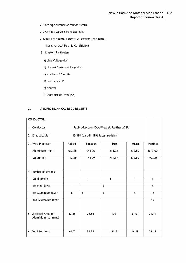
New Initiative on Material Mobilisation Report of Committee A
182
2.8 Average number of thunder storm
2.9 Altitude varying from sea level
2.10Basic horizontal Seismic Co-efficient(horizontal)
Basic vertical Seismic Co-efficient
2.11System Particulars
a) Line Voltage (kV)
b) Highest System Voltage (kV)
c) Number of Circuits
d) Frequency HZ
e) Neutral
f) Short circuit level (KA)
3. SPECIFIC TECHNICAL REQUIREMENTS
CONDUCTOR:
1. Conductor: Rabbit/Raccoon/Dog/Weasel/Panther ACSR
2. IS applicable: IS-398 (part-II) 1996 latest revision
3. Wire Diameter Rabbit Raccoon Dog Weasel Panther
Aluminium (mm) 6/3.35 6/4.06 6/4.72 6/2.59 30/3.00
Steel(mm) 1/3.35 1/4.09 7/1.57 1/2.59 7/3.00
4. Number of strands:
Steel centre 1 1 1 1
1st steel layer - 6 6
1st Aluminium layer 6 6 6 6 12
2nd Aluminium layer 18
5. Sectional Area of
Aluminium (sq. mm.)
52.88 78.83 105 31.61 212.1
6. Total Sectional 61.7 91.97 118.5 36.88 261.5
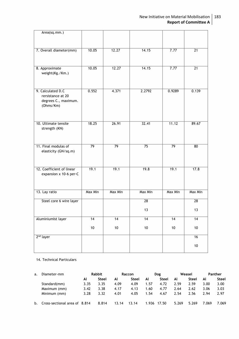
New Initiative on Material Mobilisation Report of Committee A
183
Area(sq.mm.)
7. Overall diameter(mm) 10.05
12.27
14.15 7.77 21
8. Approximate
weight(Kg./Km.)
10.05 12.27 14.15 7.77 21
9. Calculated D.C
rersistance at 20
degrees C., maximum.
(Ohms/Km)
0.552 4.371 2.2792 0.9289 0.139
10. Ultimate tensile
strength (KN)
18.25 26.91 32.41 11.12 89.67
11. Final modulas of
elasticity (GN/sq.m)
79 79 75 79 80
12. Coefficient of linear
expansion x 10-6 per◦C
19.1 19.1 19.8 19.1 17.8
13. Lay ratio Max Min Max Min Max Min Max Min Max Min
Steel core 6 wire layer 28
13
28
13
AluminiumIst layer 14
10
14
10
14
10
14
10
14
10
2nd layer
16
10
14. Technical Particulars
a. Diameter-mm
Standard(mm)
Maximum (mm)
Minimum (mm)
Rabbit Raccon Dog Weasel Panther
Al Steel Al Steel Al Steel Al Steel Al Steel
3.35 3.35 4.09 4.09 1.57 4.72 2.59 2.59 3.00 3.00
3.42 3.38 4.17 4.13 1.60 4.77 2.64 2.62 3.06 3.03
3.28 3.32 4.01 4.05 1.54 4.67 2.54 2.56 2.94 2.97
b. Cross-sectional area of 8.814 8.814 13.14 13.14 1.936 17.50 5.269 5.269 7.069 7.069
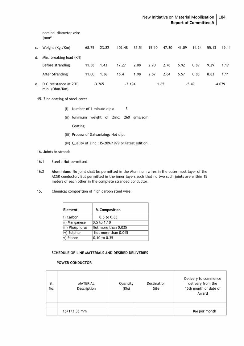
New Initiative on Material Mobilisation Report of Committee A
184
nominal diameter wire
(mm2)
c. Weight (Kg./Km) 68.75 23.82 102.48 35.51 15.10 47.30 41.09 14.24 55.13 19.11
d. Min. breaking load (KN)
Before stranding 11.58 1.43 17.27 2.08 2.70 2.78 6.92 0.89 9.29 1.17
After Stranding 11.00 1.36 16.4 1.98 2.57 2.64 6.57 0.85 8.83 1.11
e. D.C resistance at 20 ̊C
min. (Ohm/Km)
-3.265 -2.194 1.65 -5.49 -4.079
15. Zinc coating of steel core:
(i) Number of 1 minute dips: 3
(ii) Minimum weight of Zinc: 260 gms/sqm
Coating
(iii) Process of Galvanizing: Hot dip.
(iv) Quality of Zinc : IS-209/1979 or latest edition.
16. Joints in strands
16.1 Steel : Not permitted
16.2 Aluminium: No joint shall be permitted in the Aluminum wires in the outer most layer of the
ACSR conductor. But permitted in the inner layers such that no two such joints are within 15
meters of each other in the complete stranded conductor.
15. Chemical composition of high carbon steel wire:
Element % Composition
i) Carbon 0.5 to 0.85
ii) Manganese 0.5 to 1.10
iii) Phosphorus Not more than 0.035
iv) Sulphur Not more than 0.045
v) Silicon 0.10 to 0.35
SCHEDULE OF LINE MATERIALS AND DESIRED DELIVERIES
POWER CONDUCTOR
Sl.
No.
MATERIAL
Description
Quantity
(KM)
Destination
Site
Delivery to commence
delivery from the
15th month of date of
Award
16/1/3.35 mm KM per month
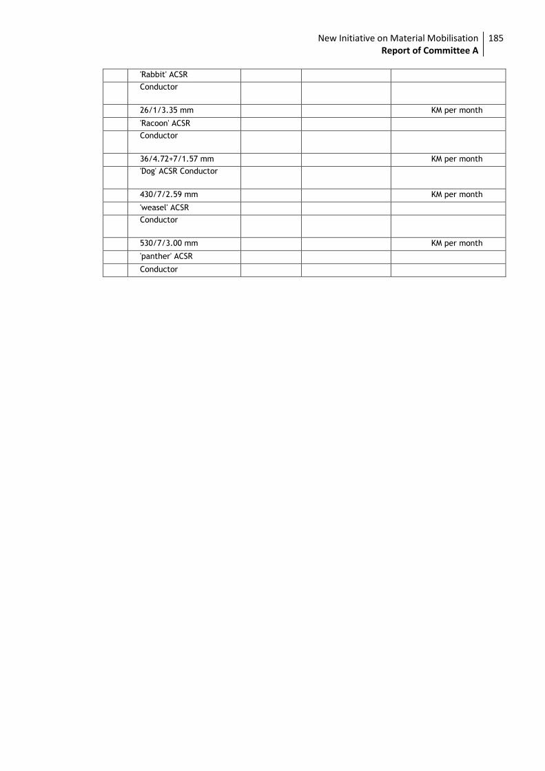
New Initiative on Material Mobilisation Report of Committee A
185
'Rabbit' ACSR
Conductor
26/1/3.35 mm KM per month
'Racoon' ACSR
Conductor
36/4.72+7/1.57 mm KM per month
'Dog' ACSR Conductor
430/7/2.59 mm KM per month
'weasel' ACSR
Conductor
530/7/3.00 mm KM per month
'panther' ACSR
Conductor
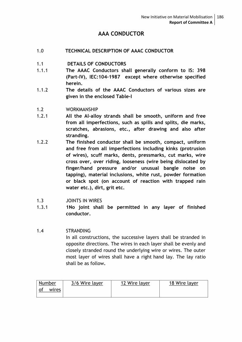
New Initiative on Material Mobilisation Report of Committee A
186
AAA CONDUCTOR
1.0 TECHNICAL DESCRIPTION OF AAAC CONDUCTOR
1.1 DETAILS OF CONDUCTORS
1.1.1 The AAAC Conductors shall generally conform to IS: 398
(Part-IV), IEC:104-1987 except where otherwise specified
herein.
1.1.2 The details of the AAAC Conductors of various sizes are
given in the enclosed Table-I
1.2 WORKMANSHIP
1.2.1 All the Al-alloy strands shall be smooth, uniform and free
from all imperfections, such as spills and splits, die marks,
scratches, abrasions, etc., after drawing and also after
stranding.
1.2.2 The finished conductor shall be smooth, compact, uniform
and free from all imperfections including kinks (protrusion
of wires), scuff marks, dents, pressmarks, cut marks, wire
cross over, over riding, looseness (wire being dislocated by
finger/hand pressure and/or unusual bangle noise on
tapping), material inclusions, white rust, powder formation
or black spot (on account of reaction with trapped rain
water etc.), dirt, grit etc.
1.3 JOINTS IN WIRES
1.3.1 1No joint shall be permitted in any layer of finished
conductor.
1.4 STRANDING
In all constructions, the successive layers shall be stranded in
opposite directions. The wires in each layer shall be evenly and
closely stranded round the underlying wire or wires. The outer
most layer of wires shall have a right hand lay. The lay ratio
shall be as follow.
Number
of wires
3/6 Wire layer 12 Wire layer 18 Wire layer
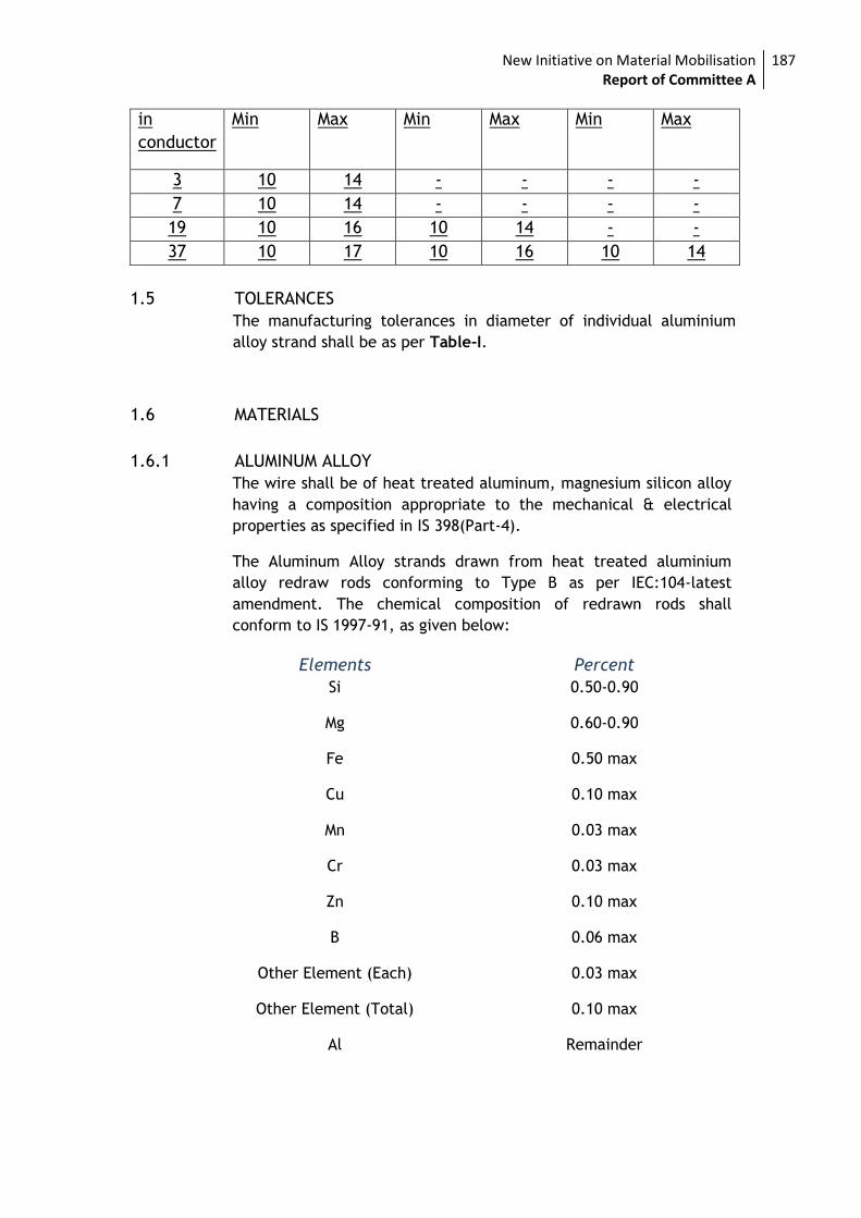
New Initiative on Material Mobilisation Report of Committee A
187
in
conductor
Min Max Min Max Min Max
3 10 14 - - - -
7 10 14 - - - -
19 10 16 10 14 - -
37 10 17 10 16 10 14
1.5 TOLERANCES
The manufacturing tolerances in diameter of individual aluminium
alloy strand shall be as per Table-I.
1.6 MATERIALS
1.6.1 ALUMINUM ALLOY
The wire shall be of heat treated aluminum, magnesium silicon alloy
having a composition appropriate to the mechanical & electrical
properties as specified in IS 398(Part-4).
The Aluminum Alloy strands drawn from heat treated aluminium
alloy redraw rods conforming to Type B as per IEC:104-latest
amendment. The chemical composition of redrawn rods shall
conform to IS 1997-91, as given below:
Elements Percent
Si 0.50-0.90
Mg 0.60-0.90
Fe 0.50 max
Cu 0.10 max
Mn 0.03 max
Cr 0.03 max
Zn 0.10 max
B 0.06 max
Other Element (Each) 0.03 max
Other Element (Total) 0.10 max
Al Remainder
New Initiative on Material Mobilisation Report of Committee A
188
1.7 STANDARD LENGTH
1.7.1 The standard length of the conductor shall be 2000 meters.
Contractor shall indicate the standard length of the
conductor to be offered by them. A tolerance of +/-5% on
the standard length offered by the Bidder shall be
permitted. All lengths outside this limit of tolerance shall be
treated as random lengths.
1.7.2 Random lengths will be accepted provided no length is less
than 70% of the standard length and the total quantity of
such random lengths shall not be more than 10% of the total
quantity ordered.
1.7.3 Bidder shall also indicate the maximum single length, above
the standard length, he can manufacture in the guaranteed
technical particulars of offer. The Owner reserves the right
to place orders for the above lengths on the same terms and
conditions applicable for the standard lengths during the
execution of the Contract.
1.8 TESTS AND STANDARDS
The following tests to be conducted for AAAC conductors shall
conform to IS 398(Part -IV) 1979 and IEC 888 & 889.
1.8.1 TYPE/PERIODIC
The following tests shall be conducted on samples of each type of
conductor :
(a) UTS test on stranded )
conductor )
) Annexure-A
(b) DC resistance test on )
stranded conductor )
1.8.2 ACCEPTANCE TESTS
(a) Visual check for joints scratches ) Annexure - A
etc. and length measurement of )
New Initiative on Material Mobilisation Report of Committee A
189
conductor by rewinding )
(b) Dimensional check on )
Al-alloy strands
(c) Check for lay-ratio )
)
(d) Elongation test ) Annexure - A
)
(e) Breaking load/tensile test on )
Aluminum alloy strands )
)
(f) DC resistance test on )
Aluminum alloy strands)
(g) Wrap test on ) IEC 104, IEC 1089
Aluminum alloy strands
(h) Visual and dimensional )
check on drum ) IS:1778-1980
1.8.3 ROUTINE TEST
(a) Check to ensure that there are no joints.
(b) Check that there are no cuts, fins etc. on the strands.
(c) Check that drums are as per Specification.
(d) All acceptance test as mentioned above to be carried out on
each coil.
New Initiative on Material Mobilisation Report of Committee A
190
1.8.4 TESTS DURING MANUFACTURE
(a) Chemical analysis of )
Aluminum alloy used for )
making strands ) Annexure-A
1.8.5 TESTING EXPENSES
i) The type test charges for the conductor should be quoted in the
relevant schedule of Bid Proposal Sheets.
ii) Contractor shall indicate the laboratories in which they propose to
conduct the type tests. They shall ensure that adequate facilities are
available in the laboratories and the tests can be completed in these
laboratories within the time schedule guaranteed by them.
iii) In case of failure in any type test, the Contractor is either required
to manufacture fresh sample lot and repeat all the tests successfully
once or repeat that particular type test three times successfully on
the sample selected from the already manufactured lot at his own
expenses. In case a fresh lot is manufactured for testing, then the
lot already manufactured shall be rejected.
iv) The entire cost of testing for the acceptance and routine tests and
Tests during manufacture specified herein shall be treated as
included in the quoted unit price of conductor, except for the
expenses of the inspector/Owner's representative.
v) In case of failure in any type test, if repeat type tests are required
to be conducted, then all the expenses for deputation of
Inspector/Owner's representative shall be deducted from the
contract price. Also if on receipt of the Contractor's notice of
testing, the Owner's representative does not find 'The material or
testing facilities' to be ready for testing the expenses incurred by the
Owner for re-deputation shall be deducted from contract price.
1.8.6 ADDITIONAL TESTS
i) The Owner reserves the right of having at his own expenses any
other test(s) of reasonable nature carried out at Contractor’s
New Initiative on Material Mobilisation Report of Committee A
191
premises, at site or in any other place in addition to the aforesaid
type, acceptance and routine tests to satisfy himself that the
materials comply with the Specifications.
ii) The Owner also reserves the right to conduct all the tests mentioned
in this specification at his own expense on the samples drawn from
the site at Contractor’s premises or at any other test centre. In case
of evidence of non-compliance, it shall be binding on the part of
Contractor to prove the compliance of the items to the technical
specifications by repeat tests, or correction of deficiencies, or
replacement of defective items all without any extra cost to the
Owner.
1.8.7 SAMPLE BATCH FOR TYPE TESTING
i) The Contractor shall offer material for selection of samples for type
testing only after getting Quality Assurance Plan approved from
Owner’s Quality Assurance Deptt. The sample shall be manufactured
strictly in accordance with the Quality Assurance Plan approved by
Owner.
ii) The Contractor shall offer at least three drums for selection of
sample required for conducting all the type tests.
iii) The Contractor is required to carry out all the acceptance tests
successfully in presence of Owner’s representative before sample
selection.
1.8.8 TEST REPORTS
i) Copies of type test reports shall be furnished in at least six copies
along with one original. One copy will be returned duly certified by
the Owner only after which the commercial production of the
material shall start.
ii) Record of routine test reports shall be maintained by the Supplier at
his works for periodic inspection by the Owner’s representative.
New Initiative on Material Mobilisation Report of Committee A
192
iii) Test Certificates of tests during manufacture shall be maintained by
the Contractor. These shall be produced for verification as and when
desired by the Owner.
1.9 INSPECTION
1.9.1 The Owner’s representative shall at all times be entitled to
have access to the works and all places of manufacture,
where conductor shall be manufactured and representative
shall have full facilities for unrestricted inspection of the
Contractor’s works, raw materials and process of
manufacture for conducting necessary tests as detailed
herein.
1.9.2 The Contractor shall keep the Owner informed in advance of
the time of starting and of the progress of manufacture of
conductor in its various stages so that arrangements can be
made for inspection.
1.9.3 No material shall be dispatched from its point of
manufacture before it has been satisfactorily inspected and
tested, unless the inspection is waived off by the Owner in
writing. In the latter case also, the conductor shall be
dispatched only after satisfactory testing for all tests
specified herein have been completed.
1.9.4 The acceptance of any quantity of material shall in no way
relieve the Contractor of any of his responsibilities for
meeting all requirements of the Specification, and shall not
prevent subsequent rejection if such material is later found
to be defective.
1.9.5 TEST FACILITIES
The following additional test facilities shall be available at the
Contractor’s works:
New Initiative on Material Mobilisation Report of Committee A
193
i) Calibration of various testing and measuring equipment
including tensile testing machine, resistance measurement
facilities, burette, thermometer, barometer etc.
ii) Standard resistance for calibration of resistance bridges.
iii) Finished conductor shall be checked for length verification
and surface finish on separate rewinding machine at reduced
speed (variable from 8 to 16 meters per minute). The
rewinding facilities shall have appropriate clutch system and
free of vibrations, jerks etc. with traverse laying facilities.
1.10 PACKING
1.10.1 The conductor shall be supplied in returnable, strong,
wooden drums provided with lagging of adequate strength,
constructed to protect the conductor against any damage
and displacement during transit, storage and subsequent
handling and stringing operations in the field. The
Contractor shall be responsible for any loss or damage
during transportation handling and storage due to improper
packing. The drums shall generally conform to IS:1778-1980,
except as otherwise specified hereinafter.
1.10.2 The drums shall be suitable for wheel mounting and for
letting off the conductor under a minimum controlled
tension of the order of 5 KN.
1.10.3 The Contractor should submit their proposed drum drawings
along with the bid.
1.10.4 The Contractor may offer more than one length of the
conductor in a single drum.
1.10.5 All wooden components shall be manufactured out of
seasoned soft wood free from defects that may materially
weaken the component parts of the drums. Preservative
treatment shall be applied to the entire drum with
New Initiative on Material Mobilisation Report of Committee A
194
preservatives of a quality, which is not harmful to the
conductor.
1.10.6 The flanges shall be of two ply construction with a total
thickness of 64 mm with each ply at right angles to the
adjacent ply and nailed together. The nails shall be driven
from the inside face flange, punched and then clenched on
the outer face. Flange boards shall not be less than the
nominal thickness by more than 2mm. There shall not be
less than 2 nails per board in each circle. Where a slot is cut
in the flange to receive the inner end of the conductor the
entrance shall be in line with the periphery of the barrel.
1.10.7 The wooden battens used for making the barrel of the
conductor shall be of segmental type. These shall be nailed
to the barrel supports with at least two nails. The battens
shall be closely butted and shall provide a round barrel with
smooth external surface. The edges of the battens shall be
rounded or chamfered to avoid damage to the conductor.
1.10.8 Barrel studs shall be used for the construction of drums. The
flanges shall be holed and the barrel supports slotted to
receive them. The barrel studs shall be threaded over a
length on either end, sufficient to accommodate washers,
spindle plates and nuts for fixing flanges at the required
spacing.
1.10.9 Normally, the nuts on the studs shall stand protruded of the
flanges. All the nails used on the inner surface of the flanges
and the drum barrel shall be counter sunk. The ends of
barrel shall generally be flushed with the top of the nuts.
1.10.10 The inner cheek of the flanges and drum barrel surface shall
be painted with a bitumen based paint.
1.10.11 Before reeling, card board or double corrugated or thick
bituminous water-proof bamboo paper shall be secured to
the drum barrel and inside of flanges of the drum by means
of a suitable commercial adhesive material. The paper
New Initiative on Material Mobilisation Report of Committee A
195
should be dried before use. After reeling the conductor, the
exposed surface of the outer layer of conductor shall be
wrapped with water proof thick bituminous bamboo paper
to preserve the conductor from dirt, grit and damage during
transport and handling.
1.10.12 A minimum space of 75 mm for conductor shall be provided
between the inner surface of the external protective lagging
and outer layer of the conductor. Outside the protective
lagging, there shall be minimum of two binders consisting of
hoop iron/ galvanized steel wire. Each protective lagging
shall have two recesses to accommodate the binders.
1.10.13 Each batten shall be securely nailed across grains as far as
possible to the flange, edges with at least 2 nails per end.
The length of the nails shall not be less than twice the
thickness of the battens. The nails shall not protrude above
the general surface and shall not have exposed sharp, edges
or allow the battens to be released due to corrosion.
1.10.14 The nuts on the barrel studs shall be tack welded on the one
side in order to fully secure them. On the second end, a
spring washer shall be used.
1.10.15 A steel collar shall be used to secure all barrel studs. This
collar shall be located between the washers and the steal
drum and secured to the central steel plate by welding.
1.10.16 Outside the protective lagging, there shall be minimum of
two binder consisting of hoop iron/ galvanized steel wire.
Each protective lagging shall have two recesses to
accommodate the binders.
1.10.17 The conductor ends shall be properly sealed and secured
with the help of U-nail on the side of one of the flanges to
avoid loosening of the conductor layers during transit and
handling.
New Initiative on Material Mobilisation Report of Committee A
196
1.10.18 As an alternative to wooden drum Contractor may also
supply the conductors in non-returnable painted steel
drums. After preparation of steel surface according to IS :
9954, synthetic enamel paint shall be applied after
application of one coat of primer. Wooden/Steel drum will
be treated at par for evaluation purpose and accordingly the
Contractor should quote in the package.
1.11 MARKING
Each drum shall have the following information stenciled on it in
indelible ink along with other essential data :
a. Contract/Award letter number.
b. Name and address of consignee.
c. Manufacturer’s name and address.
d. Drum and lot number
e. Size and type of conductor
f. Length of conductor in meters
g. Arrow marking for unwinding
h. Position of the conductor ends
i. Number of turns in the outer most layer.
j. Gross weight of drum after putting lagging.
k. Average weight of the drum without lagging.
l. Net weight of the conductor in the drum.
m. Month and year of manufacture of conductor
The above should be indicated in the packing list also.
1.12 VERIFICATION OF CONDUCTOR LENGTH
The Owner reserves the right to verity the length of conductor after
unreeling at least Two (2) percent of the drums in a lot offered for
inspection.
For the balance drums, length verification shall be done by the
owner based on report/certification from Manufacturer/Contractor.
New Initiative on Material Mobilisation Report of Committee A
197
1.13 STANDARDS
1.13.1 The conductor shall conform to the following
Indian/International Standards, which shall mean latest
revisions, with amendments/changes adopted and
published, unless specifically stated otherwise in the
Specification.
1.13.2 In the event of the supply of conductor conforming to
standards other than specified, the Bidder shall confirm in
his bid that these standards are equivalent to those
specified. In case of award, salient features of comparison
between the standards proposed by the Contractor and
those specified in this document will be provided by the
Contractor to establish their equivalence.
––––––———————————————————————————
Sl. Indian Title
International
No. Standard Standards
——————————————————————————————
1. IS:398 (Part-IV) Aluminum Alloy IEC : 208-1966
stranded conductor BS-3242-1970
2 IS : 9997-1988 Aluminum Alloy IEC 104-1987
Redraw Rods
3 IS : 1778-1980 Reels and Drums BS:1559-1949
for Bare Conductors
——————————————————————————————
New Initiative on Material Mobilisation Report of Committee A
198
ANNEXURE-A
1.0 TESTS ON AAAC CONDUCTORS
1.1 UTS Test on Stranded Conductor
Circles perpendicular to the axis of the conductor shall be marked at
two places on a sample of conductor of minimum 5 m length
between fixing arrangement suitably fixed on a tensile testing
machine. The load shall be increased at a steady rate upto 50% of
minimum specified UTS and held for one minute. The circles drawn
shall not be distorted due to relative movement of strands.
Thereafter the load shall be increased at steady rate to minimum
UTS and held for one minute. The Conductor sample shall not fail
during this period. The applied load shall then be increased until
the failing load is reached and the value recorded.
1.2 D.C. Resistance Test on Stranded Conductor
On a conductor sample of minimum 5m length two contact-clamps
shall be fixed with a predetermined bolt torque. The resistance shall
be measured by a Kelvin double bridge by placing the clamps initially
zero meter and subsequently one meter apart. The test shall be
repeated at least five times and the average value recorded. The
value obtained shall be corrected to the value at 20°C as per IS:398-
(Part-V)-1982. The resistance corrected at 200C shall conform to the
requirements of this Specification.
1.3 CHEMICAL ANALYSIS OF ALUMINIUM ALLOY
Samples taken from the Aluminium alloy ingots/coils/strands shall be
chemically/spectrographically analyzed. The same shall be in
conformity to the requirements stated in this Specification.
1.4 VISUAL AND DIMENSIONAL CHECK ON DRUMS
The drums shall be visually and dimensionally checked to ensure that
they conform to the requirements of this Specification.
1.5 VISUAL CHECK FOR JOINTS, SCRATCHES ETC.
Conductor drums shall be rewound in the presence of the Owner.
The Owner shall visually check for scratches, joints etc. and that the
conductor generally conforms to the requirements of this
Specification. Two percent (2%) drums from each lot shall be
rewound in the presence of the Owner's representative.
1.6 DIMENSIONAL CHECK ON ALUMINUM ALLOY STRANDS
The individual strands shall be dimensionally checked to ensure that
they conform to the requirement of this Specification.
1.7 CHECK FOR LAY-RATIOS OF VARIOUS LAYERS
The lay-ratios of various layers shall be checked to ensure that they
conform to the requirements of this Specification.
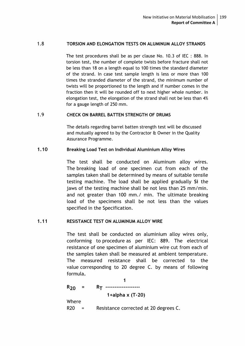
New Initiative on Material Mobilisation Report of Committee A
199
1.8 TORSION AND ELONGATION TESTS ON ALUMINUM ALLOY STRANDS
The test procedures shall be as per clause No. 10.3 of IEC : 888. In
torsion test, the number of complete twists before fracture shall not
be less than 18 on a length equal to 100 times the standard diameter
of the strand. In case test sample length is less or more than 100
times the stranded diameter of the strand, the minimum number of
twists will be proportioned to the length and if number comes in the
fraction then it will be rounded off to next higher whole number. In
elongation test, the elongation of the strand shall not be less than 4%
for a gauge length of 250 mm.
1.9 CHECK ON BARREL BATTEN STRENGTH OF DRUMS
The details regarding barrel batten strength test will be discussed
and mutually agreed to by the Contractor & Owner in the Quality
Assurance Programme.
1.10 Breaking Load Test on Individual Aluminium Alloy Wires
The test shall be conducted on Aluminum alloy wires.
The breaking load of one specimen cut from each of the
samples taken shall be determined by means of suitable tensile
testing machine. The load shall be applied gradually Si the
jaws of the testing machine shall be not less than 25 mm/min.
and not greater than 100 mm./ min. The ultimate breaking
load of the specimens shall be not less than the values
specified in the Specification.
1.11 RESISTANCE TEST ON ALUMINUM ALLOY WIRE
The test shall be conducted on aluminium alloy wires only,
conforming to procedure as per IEC: 889. The electrical
resistance of one specimen of aluminium wire cut from each of
the samples taken shall be measured at ambient temperature.
The measured resistance shall be corrected to the
value corresponding to 20 degree C. by means of following
formula.
1
R20 = RT -------------------
1+alpha x (T-20)
Where
R20 = Resistance corrected at 20 degrees C.
New Initiative on Material Mobilisation Report of Committee A
200
RT = Resistance measured at T degrees C.
alpha = Constant mass temperature coefficient of
resistance 0.004.
T = Ambient temperature during measurement
This resistance calculated to 20 degrees C. shall be not more
than the maximum value specified in the specification.
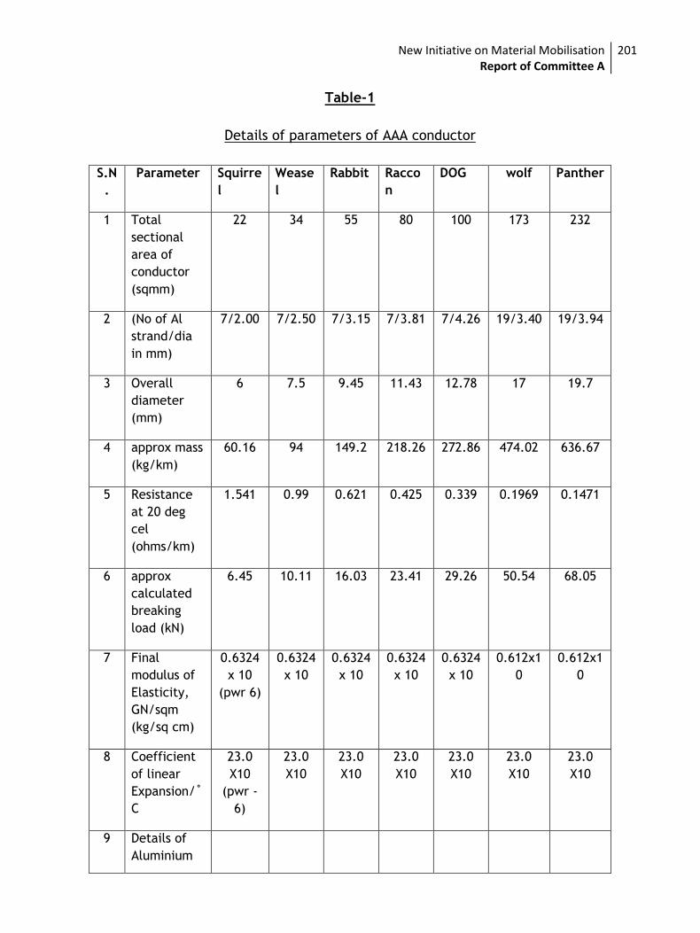
New Initiative on Material Mobilisation Report of Committee A
201
Table-1
Details of parameters of AAA conductor
S.N
.
Parameter Squirre
l
Wease
l
Rabbit Racco
n
DOG wolf Panther
1 Total
sectional
area of
conductor
(sqmm)
22 34 55 80 100 173 232
2 (No of Al
strand/dia
in mm)
7/2.00 7/2.50 7/3.15 7/3.81 7/4.26 19/3.40 19/3.94
3 Overall
diameter
(mm)
6 7.5 9.45 11.43 12.78 17 19.7
4 approx mass
(kg/km)
60.16 94 149.2 218.26 272.86 474.02 636.67
5 Resistance
at 20 deg
cel
(ohms/km)
1.541 0.99 0.621 0.425 0.339 0.1969 0.1471
6 approx
calculated
breaking
load (kN)
6.45 10.11 16.03 23.41 29.26 50.54 68.05
7 Final
modulus of
Elasticity,
GN/sqm
(kg/sq cm)
0.6324
x 10
(pwr 6)
0.6324
x 10
0.6324
x 10
0.6324
x 10
0.6324
x 10
0.612x1
0
0.612x1
0
8 Coefficient
of linear
Expansion/˚
C
23.0
X10
(pwr -
6)
23.0
X10
23.0
X10
23.0
X10
23.0
X10
23.0
X10
23.0
X10
9 Details of
Aluminium
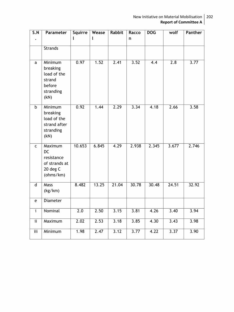
New Initiative on Material Mobilisation Report of Committee A
202
S.N
.
Parameter Squirre
l
Wease
l
Rabbit Racco
n
DOG wolf Panther
Strands
a Minimum
breaking
load of the
strand
before
stranding
(kN)
0.97 1.52 2.41 3.52 4.4 2.8 3.77
b Minimum
breaking
load of the
strand after
stranding
(kN)
0.92 1.44 2.29 3.34 4.18 2.66 3.58
c Maximum
DC
resistance
of strands at
20 deg C
(ohms/km)
10.653 6.845 4.29 2.938 2.345 3.677 2.746
d Mass
(kg/km)
8.482 13.25 21.04 30.78 30.48 24.51 32.92
e Diameter
i Nominal 2.0 2.50 3.15 3.81 4.26 3.40 3.94
ii Maximum 2.02 2.53 3.18 3.85 4.30 3.43 3.98
iii Minimum 1.98 2.47 3.12 3.77 4.22 3.37 3.90
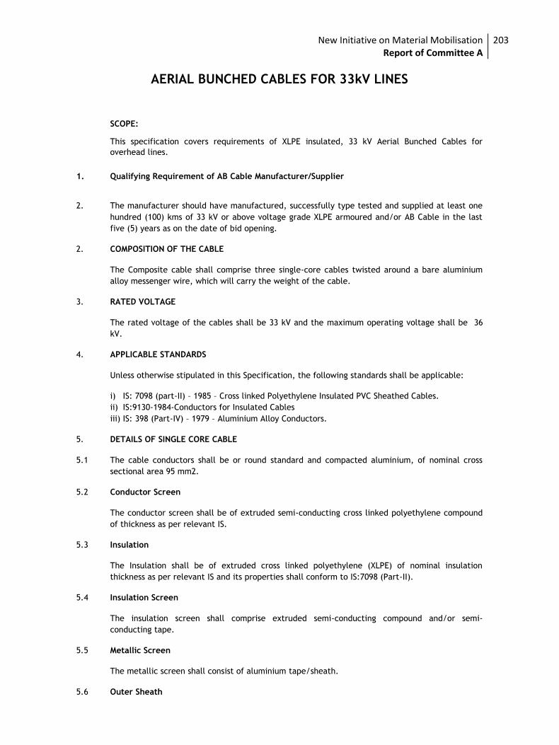
New Initiative on Material Mobilisation Report of Committee A
203
AERIAL BUNCHED CABLES FOR 33kV LINES
SCOPE:
This specification covers requirements of XLPE insulated, 33 kV Aerial Bunched Cables for
overhead lines.
1. Qualifying Requirement of AB Cable Manufacturer/Supplier
2. The manufacturer should have manufactured, successfully type tested and supplied at least one
hundred (100) kms of 33 kV or above voltage grade XLPE armoured and/or AB Cable in the last
five (5) years as on the date of bid opening.
2. COMPOSITION OF THE CABLE
The Composite cable shall comprise three single-core cables twisted around a bare aluminium
alloy messenger wire, which will carry the weight of the cable.
3. RATED VOLTAGE
The rated voltage of the cables shall be 33 kV and the maximum operating voltage shall be 36
kV.
4. APPLICABLE STANDARDS
Unless otherwise stipulated in this Specification, the following standards shall be applicable:
i) IS: 7098 (part-II) – 1985 – Cross linked Polyethylene Insulated PVC Sheathed Cables.
ii) IS:9130-1984-Conductors for Insulated Cables
iii) IS: 398 (Part-IV) – 1979 – Aluminium Alloy Conductors.
5. DETAILS OF SINGLE CORE CABLE
5.1 The cable conductors shall be or round standard and compacted aluminium, of nominal cross
sectional area 95 mm2.
5.2 Conductor Screen
The conductor screen shall be of extruded semi-conducting cross linked polyethylene compound
of thickness as per relevant IS.
5.3 Insulation
The Insulation shall be of extruded cross linked polyethylene (XLPE) of nominal insulation
thickness as per relevant IS and its properties shall conform to IS:7098 (Part-II).
5.4 Insulation Screen
The insulation screen shall comprise extruded semi-conducting compound and/or semi-
conducting tape.
5.5 Metallic Screen
The metallic screen shall consist of aluminium tape/sheath.
5.6 Outer Sheath
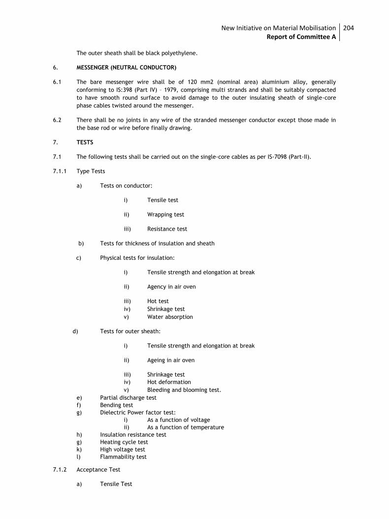
New Initiative on Material Mobilisation Report of Committee A
204
The outer sheath shall be black polyethylene.
6. MESSENGER (NEUTRAL CONDUCTOR)
6.1 The bare messenger wire shall be of 120 mm2 (nominal area) aluminium alloy, generally
conforming to IS:398 (Part IV) – 1979, comprising multi strands and shall be suitably compacted
to have smooth round surface to avoid damage to the outer insulating sheath of single-core
phase cables twisted around the messenger.
6.2 There shall be no joints in any wire of the stranded messenger conductor except those made in
the base rod or wire before finally drawing.
7. TESTS
7.1 The following tests shall be carried out on the single-core cables as per IS-7098 (Part-II).
7.1.1 Type Tests
a) Tests on conductor:
i) Tensile test
ii) Wrapping test
iii) Resistance test
b) Tests for thickness of insulation and sheath
c) Physical tests for insulation:
i) Tensile strength and elongation at break
ii) Agency in air oven
iii) Hot test
iv) Shrinkage test
v) Water absorption
d) Tests for outer sheath:
i) Tensile strength and elongation at break
ii) Ageing in air oven
iii) Shrinkage test
iv) Hot deformation
v) Bleeding and blooming test.
e) Partial discharge test
f) Bending test
g) Dielectric Power factor test:
i) As a function of voltage
ii) As a function of temperature
h) Insulation resistance test
g) Heating cycle test
k) High voltage test
l) Flammability test
7.1.2 Acceptance Test
a) Tensile Test
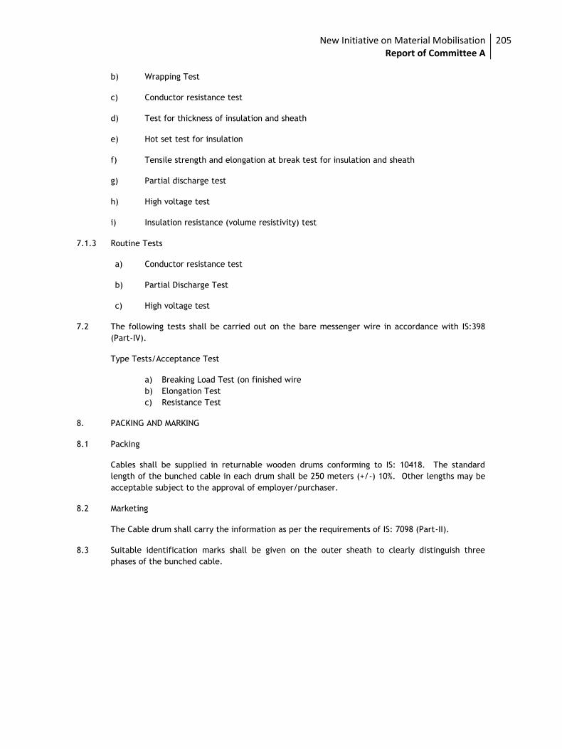
New Initiative on Material Mobilisation Report of Committee A
205
b) Wrapping Test
c) Conductor resistance test
d) Test for thickness of insulation and sheath
e) Hot set test for insulation
f) Tensile strength and elongation at break test for insulation and sheath
g) Partial discharge test
h) High voltage test
i) Insulation resistance (volume resistivity) test
7.1.3 Routine Tests
a) Conductor resistance test
b) Partial Discharge Test
c) High voltage test
7.2 The following tests shall be carried out on the bare messenger wire in accordance with IS:398
(Part-IV).
Type Tests/Acceptance Test
a) Breaking Load Test (on finished wire
b) Elongation Test
c) Resistance Test
8. PACKING AND MARKING
8.1 Packing
Cables shall be supplied in returnable wooden drums conforming to IS: 10418. The standard
length of the bunched cable in each drum shall be 250 meters (+/-) 10%. Other lengths may be
acceptable subject to the approval of employer/purchaser.
8.2 Marketing
The Cable drum shall carry the information as per the requirements of IS: 7098 (Part-II).
8.3 Suitable identification marks shall be given on the outer sheath to clearly distinguish three
phases of the bunched cable.
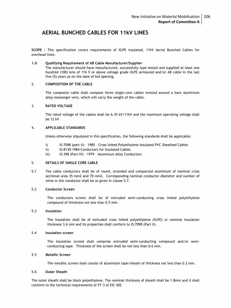
New Initiative on Material Mobilisation Report of Committee A
206
AERIAL BUNCHED CABLES FOR 11kV LINES
SCOPE : This specification covers requirements of XLPE insulated, 11kV Aerial Bunched Cables for
overhead lines.
1.0 Qualifying Requirement of AB Cable Manufacturer/Supplier
The manufacturer should have manufactured, successfully type tested and supplied at least one
hundred (100) kms of 11k V or above voltage grade XLPE armoured and/or AB cable in the last
five (5) years as on the date of bid opening.
2. COMPOSITION OF THE CABLE
The composite cable shall compose three single-core cables twisted around a bare aluminium
alloy messenger wire, which will carry the weight of the cable.
3. RATED VOLTAGE
The rated voltage of the cables shall be 6.35 kV/11kV and the maximum operating voltage shall
be 12 kV
4. APPLICABLE STANDARDS
Unless otherwise stipulated in this specification, the following standards shall be applicable:
i) IS:7098 (part-II) – 1985 – Cross linked Polyethylene Insulated PVC Sheathed Cables
ii) IS:8130-1984-Conductors for Insulated Cables
iii) IS:398 (Part-IV) – 1979 – Aluminium Alloy Conductors
5. DETAILS OF SINGLE CORE CABLE
5.1 The cable conductors shall be of round, stranded and compacted aluminium of nominal cross
sectional area 35 mm2 and 70 mm2. Corresponding nominal conductor diameter and number of
wires in the conductor shall be as given in clause 5.7.
5.2 Conductor Screen
The conductors screen shall be of extruded semi-conducting cross linked polyethylene
compound of thickness not less than 0.5 mm.
5.3 Insulation
The Insulation shall be of extruded cross linked polyethylene (XLPE) or nominal insulation
thickness 3.6 mm and its properties shall conform to IS:7098 (Part II).
5.4 Insulation screen
The Insulation screed shall comprise extruded semi-conducting compound and/or semi-
conducting tape. Thickness of the screen shall be not less than 0.6 mm.
5.5 Metallic Screen
The metallic screen shall consist of aluminium tape/sheath of thickness not less than 0.2 mm.
5.6 Outer Sheath
The outer sheath shall be black polyethylene. The nominal thickness of sheath shall be 1.8mm and it shall
conform to the technical requirements of ST-3 of EIC-502
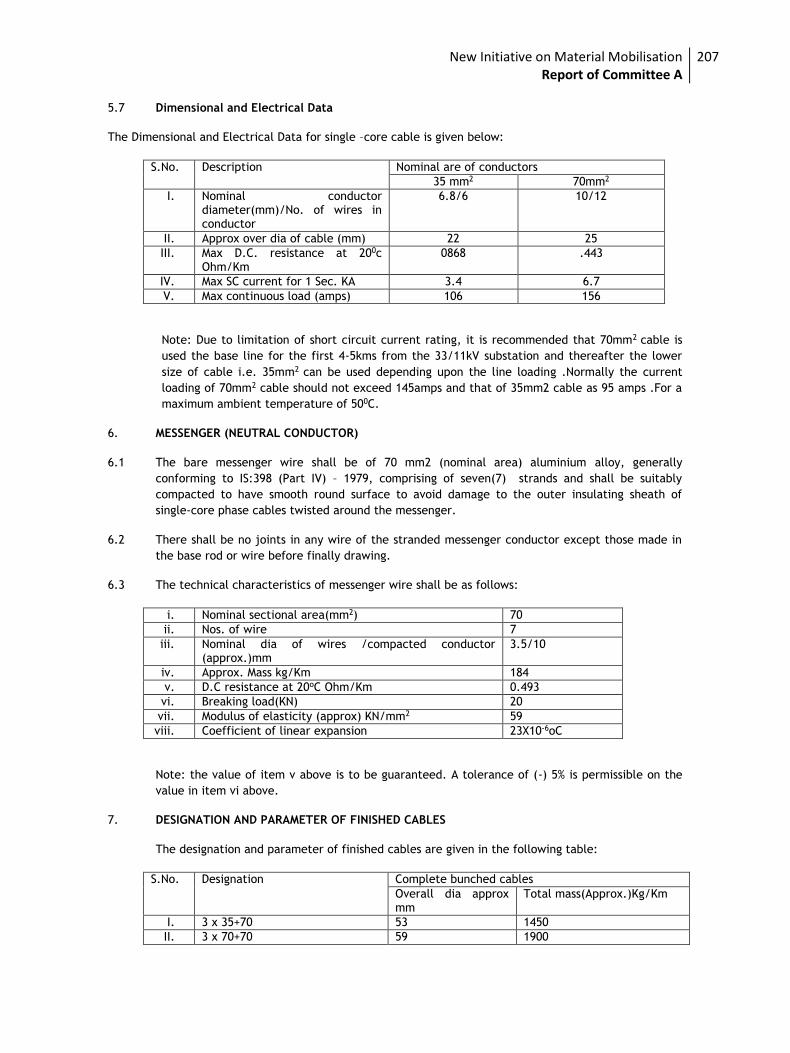
New Initiative on Material Mobilisation Report of Committee A
207
5.7 Dimensional and Electrical Data
The Dimensional and Electrical Data for single –core cable is given below:
S.No. Description Nominal are of conductors
35 mm2 70mm2
I. Nominal conductor diameter(mm)/No. of wires in conductor
6.8/6 10/12
II. Approx over dia of cable (mm) 22 25
III. Max D.C. resistance at 200c Ohm/Km
0868 .443
IV. Max SC current for 1 Sec. KA 3.4 6.7
V. Max continuous load (amps) 106 156
Note: Due to limitation of short circuit current rating, it is recommended that 70mm2 cable is
used the base line for the first 4-5kms from the 33/11kV substation and thereafter the lower
size of cable i.e. 35mm2 can be used depending upon the line loading .Normally the current
loading of 70mm2 cable should not exceed 145amps and that of 35mm2 cable as 95 amps .For a
maximum ambient temperature of 500C.
6. MESSENGER (NEUTRAL CONDUCTOR)
6.1 The bare messenger wire shall be of 70 mm2 (nominal area) aluminium alloy, generally
conforming to IS:398 (Part IV) – 1979, comprising of seven(7) strands and shall be suitably
compacted to have smooth round surface to avoid damage to the outer insulating sheath of
single-core phase cables twisted around the messenger.
6.2 There shall be no joints in any wire of the stranded messenger conductor except those made in
the base rod or wire before finally drawing.
6.3 The technical characteristics of messenger wire shall be as follows:
i. Nominal sectional area(mm2) 70
ii. Nos. of wire 7
iii. Nominal dia of wires /compacted conductor (approx.)mm
3.5/10
iv. Approx. Mass kg/Km 184
v. D.C resistance at 20oC Ohm/Km 0.493
vi. Breaking load(KN) 20
vii. Modulus of elasticity (approx) KN/mm2 59
viii. Coefficient of linear expansion 23X10-6oC
Note: the value of item v above is to be guaranteed. A tolerance of (-) 5% is permissible on the
value in item vi above.
7. DESIGNATION AND PARAMETER OF FINISHED CABLES
The designation and parameter of finished cables are given in the following table:
S.No. Designation Complete bunched cables
Overall dia approx mm
Total mass(Approx.)Kg/Km
I. 3 x 35+70 53 1450
II. 3 x 70+70 59 1900
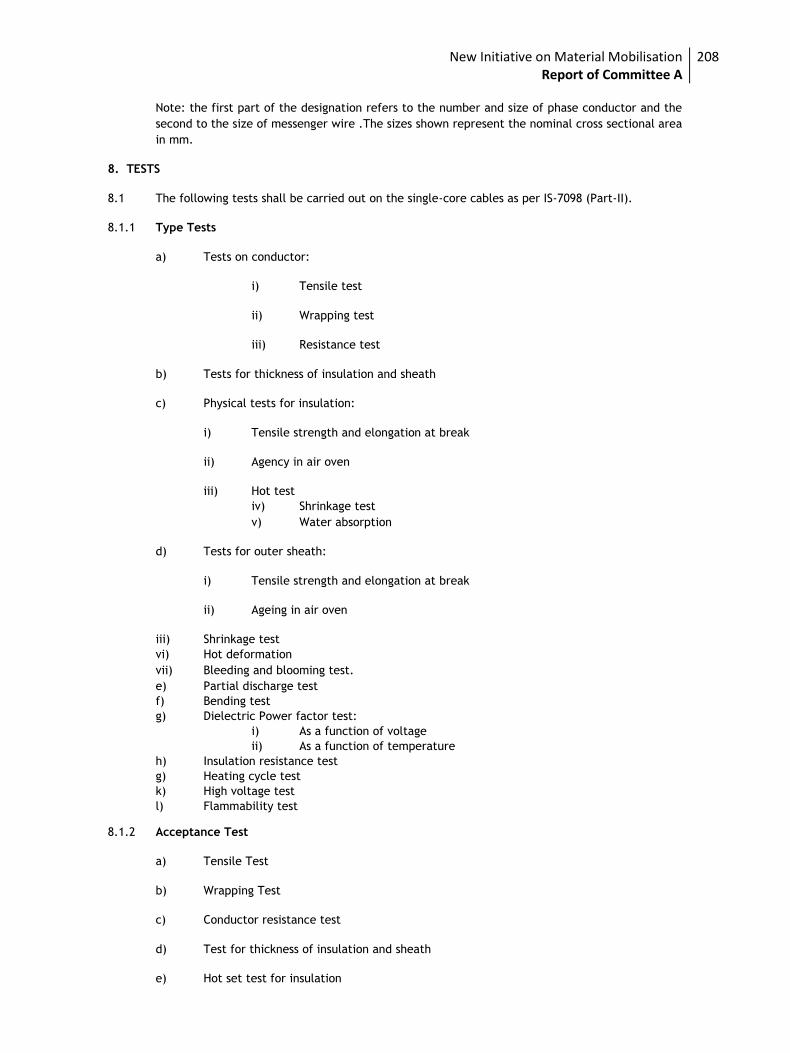
New Initiative on Material Mobilisation Report of Committee A
208
Note: the first part of the designation refers to the number and size of phase conductor and the
second to the size of messenger wire .The sizes shown represent the nominal cross sectional area
in mm.
8. TESTS
8.1 The following tests shall be carried out on the single-core cables as per IS-7098 (Part-II).
8.1.1 Type Tests
a) Tests on conductor:
i) Tensile test
ii) Wrapping test
iii) Resistance test
b) Tests for thickness of insulation and sheath
c) Physical tests for insulation:
i) Tensile strength and elongation at break
ii) Agency in air oven
iii) Hot test
iv) Shrinkage test
v) Water absorption
d) Tests for outer sheath:
i) Tensile strength and elongation at break
ii) Ageing in air oven
iii) Shrinkage test
vi) Hot deformation
vii) Bleeding and blooming test.
e) Partial discharge test
f) Bending test
g) Dielectric Power factor test:
i) As a function of voltage
ii) As a function of temperature
h) Insulation resistance test
g) Heating cycle test
k) High voltage test
l) Flammability test
8.1.2 Acceptance Test
a) Tensile Test
b) Wrapping Test
c) Conductor resistance test
d) Test for thickness of insulation and sheath
e) Hot set test for insulation
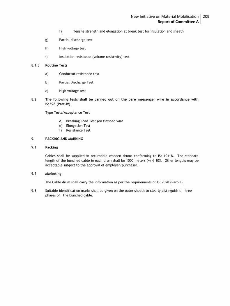
New Initiative on Material Mobilisation Report of Committee A
209
f) Tensile strength and elongation at break test for insulation and sheath
g) Partial discharge test
h) High voltage test
i) Insulation resistance (volume resistivity) test
8.1.3 Routine Tests
a) Conductor resistance test
b) Partial Discharge Test
c) High voltage test
8.2 The following tests shall be carried out on the bare messenger wire in accordance with
IS:398 (Part-IV).
Type Tests/Acceptance Test
d) Breaking Load Test (on finished wire
e) Elongation Test
f) Resistance Test
9. PACKING AND MARKING
9.1 Packing
Cables shall be supplied in returnable wooden drums conforming to IS: 10418. The standard
length of the bunched cable in each drum shall be 1000 meters (+/-) 10%. Other lengths may be
acceptable subject to the approval of employer/purchaser.
9.2 Marketing
The Cable drum shall carry the information as per the requirements of IS: 7098 (Part-II).
9.3 Suitable identification marks shall be given on the outer sheath to clearly distinguish t hree
phases of the bunched cable.
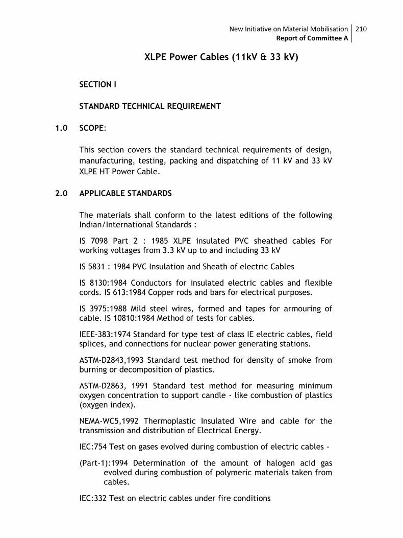
New Initiative on Material Mobilisation Report of Committee A
210
XLPE Power Cables (11kV & 33 kV)
SECTION I
STANDARD TECHNICAL REQUIREMENT
1.0 SCOPE:
This section covers the standard technical requirements of design,
manufacturing, testing, packing and dispatching of 11 kV and 33 kV
XLPE HT Power Cable.
2.0 APPLICABLE STANDARDS
The materials shall conform to the latest editions of the following Indian/International Standards :
IS 7098 Part 2 : 1985 XLPE insulated PVC sheathed cables For working voltages from 3.3 kV up to and including 33 kV
IS 5831 : 1984 PVC Insulation and Sheath of electric Cables
IS 8130:1984 Conductors for insulated electric cables and flexible cords. IS 613:1984 Copper rods and bars for electrical purposes.
IS 3975:1988 Mild steel wires, formed and tapes for armouring of cable. IS 10810:1984 Method of tests for cables.
IEEE-383:1974 Standard for type test of class IE electric cables, field splices, and connections for nuclear power generating stations.
ASTM-D2843,1993 Standard test method for density of smoke from burning or decomposition of plastics.
ASTM-D2863, 1991 Standard test method for measuring minimum oxygen concentration to support candle - like combustion of plastics (oxygen index).
NEMA-WC5,1992 Thermoplastic Insulated Wire and cable for the transmission and distribution of Electrical Energy.
IEC:754 Test on gases evolved during combustion of electric cables -
(Part-1):1994 Determination of the amount of halogen acid gas evolved during combustion of polymeric materials taken from cables.
IEC:332 Test on electric cables under fire conditions
New Initiative on Material Mobilisation Report of Committee A
211
(Part I):1993 Test on a single vertical insulated wire or cable. IS 3961 Recommended current rating for cables -
(Part II):1967 PVC insulated and PVC sheathed heavy duty cables.
IS 10418:1982 Drums for electric cables.
3.0 GENERAL REQUIREMENTS
All cables shall be suitable for high ambient, high humid tropical Indian Climatic conditions. Cables shall be designed to withstand the mechanical, electrical and thermal stresses under the unforeseen steady state and transient conditions and shall be suitable for proposed method of installation.
Conductor shall be of uniform, of good quality, free from defects Aluminium copper.
Insulation shall be Cross Linked Polyethylene (XLPE) .
For 33 kV and 11 kV cables, conductor screen and insulation screen shall both be extruded, semi-conducting compound and shall be applied along-with XLPE insulation in a single operation by triple extrusion process. Method of curing for 33 kV cable shall be "Dry curing/ gas curing " only, whereas for 11 kV and 3.3 kV cables it shall be "Dry curing/ gas curing / Steam curing".
Extruded Semi-conducting screening and metallic screening of copper tape shall be generally as per IS 7098 (Part-II) with latest amendments. The semi conducting compound shall be suitable for the operating temperature of the cable and compatible with the insulating material.
The insulation screen shall be an extruded layer of black semi-conducting compound and continuously covers the whole area of insulation. The semi-conducting screens should be effectively cross linked to achieve 90 ᵒ C cable rating. The contact surface between insulation and insulation screen shall be smooth and free from protrusion and irregularities.
The interface between insulation and insulation screen shall be free of any voids. Insulation screen shall be strippable type.
The metallic screen shall consist of a layer of copper cable applied in helical form.
Inner sheath - All armoured and multi-core un-armoured cables shall have distinct extruded inner PVC sheath of black colour.
Armouring - Material for armour for Single Core Cable shall be Aluminum wire. For Multicore cable it shall be GS wire / flat.
New Initiative on Material Mobilisation Report of Committee A
212
Armouring shall be as per relevant IS and it shall have minimum 90% coverage.
Breaking Load of the joints shall be minimum 95% of the normal armour.
Outer Sheath – It shall be of black colour PVC (type ST2 as per IS 5831) with Cable size and Voltage grade embossed on it. Sequential marking shall be at every 1 (one ) Meter distance. Word "FRLS" shall also be embossed on it at every 5 (Five ) meter distance.
FRLS Properties - All cable shall be Flame Retardant, Low Smoke (FRLS) type. Outer sheath shall have the following properties –
Acid Gas Generation – Max 20% ( as per IEC 754-1)
Smoke density rating: 60% (As per ASTMD 2843)
Flammability test - As per Swedish chimney test F3 as per SEN 4241475
As per IEC 332 part-3 (Category B)
Minimum bending radius shall be 10 D
Repaired cables shall not be acceptable.
4.0 CURRENT RATING OF CABLES
1) Normal current rating shall not be less than that covered by IS 3961. Vendor shall submit data in respect of all cables in the prescribed format.
2) Tables given de-rating factors for various conditions of cable installation including the following, for all types of cables shall be furnished.
- Variation in ambient air temperature. - Variation in ground
temperature.
- Depth of laying.
- Cables laid in the ground - Cables laid in trench
- Cables laid in ducts - Soil resistivity.
- Grouping of cables.
3) The value of short circuit withstand current ratings of all cables shall be indicated for a short circuit for 1 second duration and should also specify the maximum temperature during short circuit.
4) The following factors shall also be accounted for, while specifying the maximum short circuit withstand of the cables.
New Initiative on Material Mobilisation Report of Committee A
213
5) Deformation of the insulation, due to thermo-mechanical forces produced by the short circuit conditions, can reduce the effective thickness of insulation.
6) Conductor and core screens can be adversely affected with loss of screening effect. Likewise the thermal properties of the outer sheath material can be the limitation.
7) It is essential that the accessories which are used in the cable system with mechanical and/or soldered connections are suitable for the temperature adopted for the cables.
8) Formula for calculating short circuit current for different duration or curve showing short time current v/s time for different sizes of cables shall be furnished by vendor.
5.0 CABLE DRUMS
5.1 Cables shall be supplied in non-returnable wooden or steel drums of heavy construction and drum shall be properly seasoned, sound and free from defects. Wood preservative shall be applied to the entire drum.
5.2 All Power Cables shall be supplied in drum length of 1000 m. Each drum shall contain one continuous length of cable. Owner shall have the option of rejecting cable drums with shorter lengths. The cable length per drum is allowed a tolerance of +5%. The tolerance allowed on total quantity of each size is as given below.
3.1 50 meters for cable length upto 10 kms. 3.2 100 meters for cable length more than 10 kms. and up to 20 kms. 3.3 150 meters for cable length more than 20 kms.
Where the ordered quantity is not multiple of 1000 m and the incremental quantity is very small, the same may be included in one of the drums. Otherwise, an additional length for the incremental quantity will be supplied.
5.3 A layer of water proof paper shall be applied to the surface of the drums and over the outer most cable layer.
5.4 A clear space of at least 40mm shall be left between the cables and the logging.
5.5 Each drum shall carry manufacturer’s name, purchaser’s name, address and contract number, item number and type, size and length of the cable, net and gross weight stenciled on both sides of drum. A tag containing the same information shall be attached to the leading end of the cable. An arrow and suitable accompanying wordings shall be marked on one end of the reel indicating the direction in which it
New Initiative on Material Mobilisation Report of Committee A
214
should be rolled.
5.6 Packing shall be sturdy and adequate to protect the cables, from any injury due to mishandling or other conditions encountered during transportation, handling and storage. Both cable ends shall be sealed with PVC/Rubber caps so as to eliminate ingress of water during transportation and erection.
6.0 TESTS
6.1 Type Tests
The following shall constitute type tests:
i) Tests on conductor
a. Annealing test (for copper)
b. Tensile tests (for aluminium)
c. Wrapping tests (for aluminium)
d. Resistance test
ii) Tests for armouring wires/strips
iii) Test for thickness of insulation and sheath
iv) Physical tests for insulation
a. Tensile strength and elongation at break
b. Ageing in air oven
c. Hot test
d. Shrinkage test
e. Water absorption (gravimetric)
v) Physical tests for out sheath
a. Tensile strength and elongation at break
b. Ageing in air oven
c. Hot test
d. Shrinkage test
vi) Bleeding and blooming tests (for outer sheath)
vii) Partial discharge test
viii) Bending test
ix) Dielectric power factor test
a. As a function of voltage
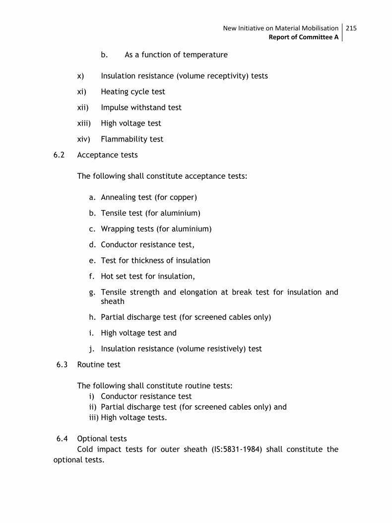
New Initiative on Material Mobilisation Report of Committee A
215
b. As a function of temperature
x) Insulation resistance (volume receptivity) tests
xi) Heating cycle test
xii) Impulse withstand test
xiii) High voltage test
xiv) Flammability test
6.2 Acceptance tests
The following shall constitute acceptance tests:
a. Annealing test (for copper)
b. Tensile test (for aluminium)
c. Wrapping tests (for aluminium)
d. Conductor resistance test,
e. Test for thickness of insulation
f. Hot set test for insulation,
g. Tensile strength and elongation at break test for insulation and sheath
h. Partial discharge test (for screened cables only)
i. High voltage test and
j. Insulation resistance (volume resistively) test
6.3 Routine test
The following shall constitute routine tests:
i) Conductor resistance test
ii) Partial discharge test (for screened cables only) and
iii) High voltage tests.
6.4 Optional tests
Cold impact tests for outer sheath (IS:5831-1984) shall constitute the
optional tests.

New Initiative on Material Mobilisation Report of Committee A
216
SECTION II
SPECIFIC TECHNICAL REQUIREMENTS AND QUANTITIES.
1.0 SCOPE
This section of the specification covers project information, site
condition, desired Technical parameters and quantity of XLPE Cable.
1.1 Project Information
a. Customer :
b. Engineer/Consultant :
c. Project Location :
d. Transport facilities
i) Nearest Railway station : /Gauge
ii) Distance from site :
e. Access Roads :
1.2 SITE CONDITIONS
(i) Ambient air temp. (max.) °C :
(ii) Ambient air temp. (min.) °C :
(iii) Design ambient temp. °C :
1.2.1 Relative humidity for design : purposes
1.2.2 Height above mean sea level in : meters
1.2.3 Earth quake data
i) Seismic zone : IS:1893-84 ii) Seismic acceleration : As per IS 2.2.4
1.2.4 Wind data
Site Wind Pressure Kgf/m2 : As per IS 2.3
1.3 System Particulars
a. Line Voltage (kV) 11/33
b.
Highest System Voltage
(kV) 12/36
c. Number of Circuits 1
d. Frequency HZ50
e. Neutral effectively earthed
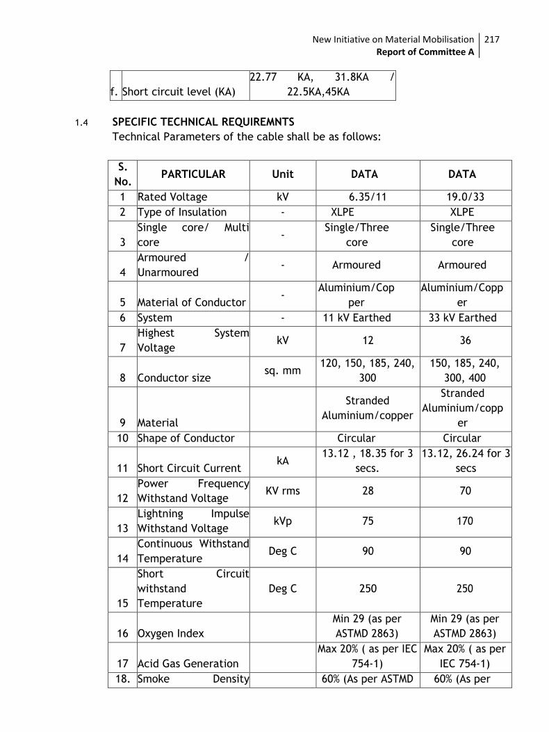
New Initiative on Material Mobilisation Report of Committee A
217
f. Short circuit level (KA)
22.77 KA, 31.8KA /
22.5KA,45KA
1.4 SPECIFIC TECHNICAL REQUIREMNTS
Technical Parameters of the cable shall be as follows:
S.
No. PARTICULAR Unit DATA DATA
1 Rated Voltage kV 6.35/11 19.0/33
2 Type of Insulation - XLPE XLPE
3
Single core/ Multi
core -
Single/Three
core
Single/Three
core
4
Armoured /
Unarmoured - Armoured Armoured
5 Material of Conductor -
Aluminium/Cop
per
Aluminium/Copp
er
6 System - 11 kV Earthed 33 kV Earthed
7
Highest System
Voltage kV 12 36
8 Conductor size sq. mm
120, 150, 185, 240,
300
150, 185, 240,
300, 400
9 Material
Stranded
Aluminium/copper
Stranded
Aluminium/copp
er
10 Shape of Conductor Circular Circular
11 Short Circuit Current kA
13.12 , 18.35 for 3
secs.
13.12, 26.24 for 3
secs
12
Power Frequency
Withstand Voltage KV rms 28 70
13
Lightning Impulse
Withstand Voltage kVp 75 170
14
Continuous Withstand
Temperature Deg C 90 90
15
Short Circuit
withstand
Temperature
Deg C 250 250
16 Oxygen Index
Min 29 (as per
ASTMD 2863)
Min 29 (as per
ASTMD 2863)
17 Acid Gas Generation
Max 20% ( as per IEC
754-1)
Max 20% ( as per
IEC 754-1)
18. Smoke Density 60% (As per ASTMD 60% (As per
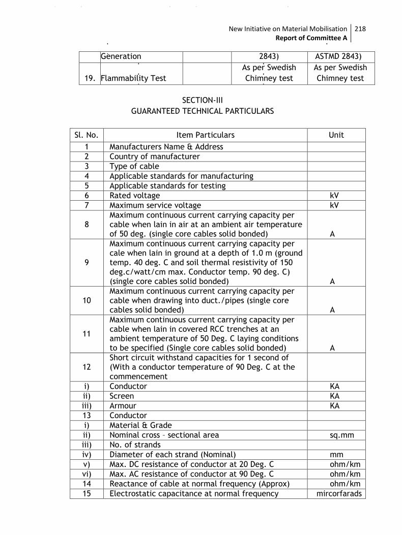
New Initiative on Material Mobilisation Report of Committee A
218
Generation 2843) ASTMD 2843)
19. Flammability Test
As per Swedish
Chimney test
As per Swedish
Chimney test
SECTION-III
GUARANTEED TECHNICAL PARTICULARS
Sl. No. Item Particulars Unit
1 Manufacturers Name & Address
2 Country of manufacturer
3 Type of cable
4 Applicable standards for manufacturing
5 Applicable standards for testing
6 Rated voltage kV
7 Maximum service voltage kV
8 Maximum continuous current carrying capacity per cable when lain in air at an ambient air temperature of 50 deg. (single core cables solid bonded) A
9
Maximum continuous current carrying capacity per cale when lain in ground at a depth of 1.0 m (ground temp. 40 deg. C and soil thermal resistivity of 150 deg.c/watt/cm max. Conductor temp. 90 deg. C) (single core cables solid bonded) A
10 Maximum continuous current carrying capacity per cable when drawing into duct./pipes (single core cables solid bonded) A
11
Maximum continuous current carrying capacity per cable when lain in covered RCC trenches at an ambient temperature of 50 Deg. C laying conditions to be specified (Single core cables solid bonded) A
12 Short circuit withstand capacities for 1 second of (With a conductor temperature of 90 Deg. C at the commencement
i) Conductor KA
ii) Screen KA
iii) Armour KA
13 Conductor
i) Material & Grade
ii) Nominal cross – sectional area sq.mm
iii) No. of strands
iv) Diameter of each strand (Nominal) mm
v) Max. DC resistance of conductor at 20 Deg. C ohm/km
vi) Max. AC resistance of conductor at 90 Deg. C ohm/km
14 Reactance of cable at normal frequency (Approx) ohm/km
15 Electrostatic capacitance at normal frequency mircorfarads
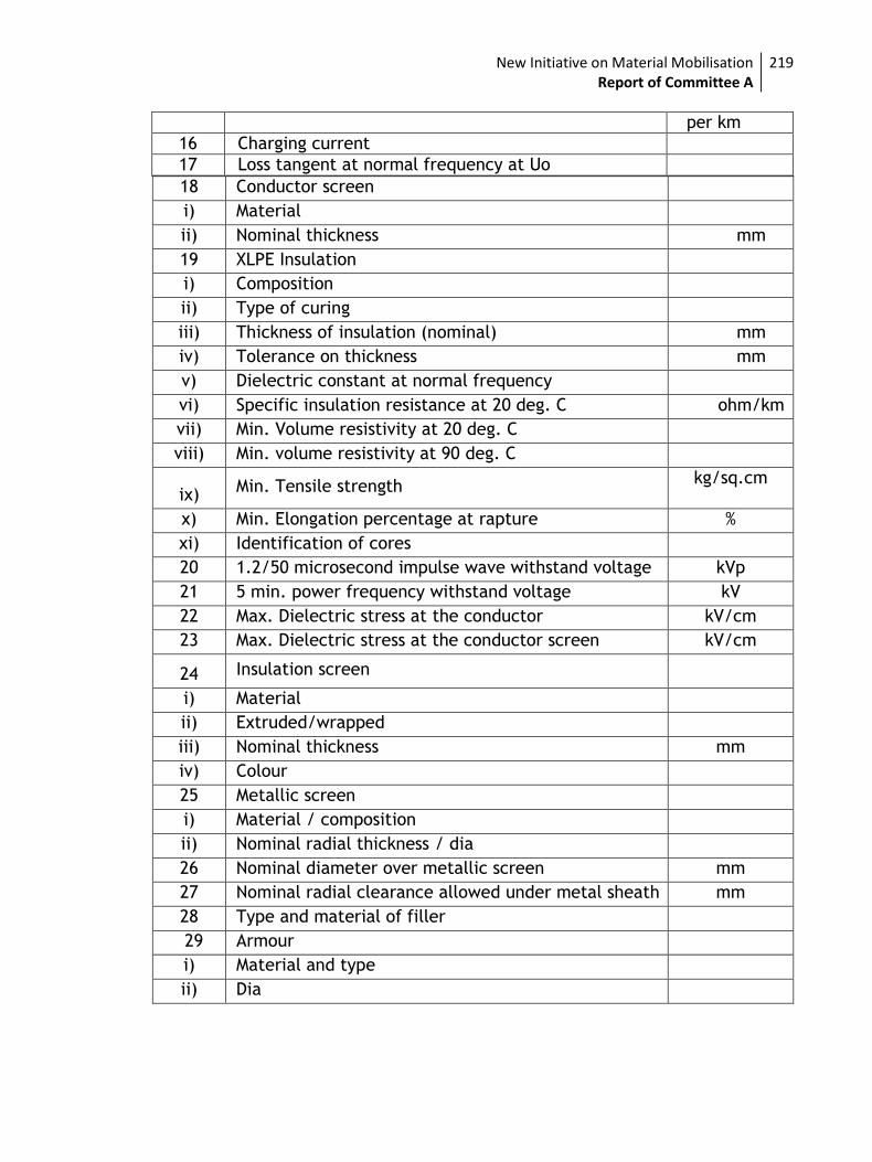
New Initiative on Material Mobilisation Report of Committee A
219
per km
16 Charging current
17 Loss tangent at normal frequency at Uo
18 Conductor screen
i) Material
ii) Nominal thickness mm
19 XLPE Insulation
i) Composition
ii) Type of curing
iii) Thickness of insulation (nominal) mm
iv) Tolerance on thickness mm
v) Dielectric constant at normal frequency
vi) Specific insulation resistance at 20 deg. C ohm/km
vii) Min. Volume resistivity at 20 deg. C
viii) Min. volume resistivity at 90 deg. C
ix) Min. Tensile strength
kg/sq.cm
x) Min. Elongation percentage at rapture %
xi) Identification of cores
20 1.2/50 microsecond impulse wave withstand voltage kVp
21 5 min. power frequency withstand voltage kV
22 Max. Dielectric stress at the conductor kV/cm
23 Max. Dielectric stress at the conductor screen kV/cm
24 Insulation screen
i) Material
ii) Extruded/wrapped
iii) Nominal thickness mm
iv) Colour
25 Metallic screen
i) Material / composition
ii) Nominal radial thickness / dia
26 Nominal diameter over metallic screen mm
27 Nominal radial clearance allowed under metal sheath mm
28 Type and material of filler
29 Armour
i) Material and type
ii) Dia
New Initiative on Material Mobilisation Report of Committee A
220
ENERGY METER
1.1 GENERAL
This Chapter describes the common requirement for static energy meter required for HT feeder, 3-Phase Distribution Transformer, 1-Phase Distribution Transformer, Single Phase whole current meter.
Necessary software for downloading the data through CMRI and uploading to computer shall be provided. No cost shall be charged for providing the software by the manufacturer to Owner.
The seals & sealing specifications are given in Annexure A
All meter shall have BIS certification mark. Valid BIS license must be submitted along with the bid.
1.2 STANDARDS APPLICABLE
Unless otherwise specified elsewhere in this specification, the performance & testing of the
meters shall conform to the following Indian/International standards with updated and latest
amendments/revisions thereof.
Sl.No. Standard No. Title
1. IS 14697-1999 AC Static Watt-hour Meters for active energy Class0.5 & 0.2
2. IS 12063 Specification for degree of protection
3. IS 14772 Specification for boxes for enclosure of electrical
accessories
4. IS 13779/1999 AC Static Watthour Meters for active energy Class 1.0 & 2.0
5. CBIP Report No.-325 Specification for AC Static Electrical Energy Meters
6. CBIP Technical
Report No. 111
Specification for common meter reading
instrument
7. IS:9000 Basic environment testing procedure for electric and
electronic item
8. IS:15959 with latest
amendment
Data Exchange for Electricity Meter Reading, tariff & load
control – Companion Specification
1.3 CLIMATIC CONDITION
The meter should be able to perform satisfactorily in moderately hot and humid climate,
conducive to rust and fungus growth as specified in Section-I. The climate conditions are also
prone to wide variations in the ambient conditions. The meter shall work satisfactorily even
under lightning conditions and also the meter performance and life shall not be affected due to
smoke present in the atmosphere.
* The specifications are applicable for meter installation upto an altitude of 2200 meter above
mean sea level. For meters to be used for an altitude of above 2200 MSL necessary corrections
shall have to be carried out in BIL and one minute power frequency with stand voltage capability
as per relevant standard.
New Initiative on Material Mobilisation Report of Committee A
221
1.4 SUPPLY SYSTEM
Type of
meter
Input
Voltage
Input
Current
Burden Type
/Phase
Starting
Current
Accuracy
HT Feeder
meter
3 x 110
volt phase
to phase
1A / 5A 1.5 Watts/phase or
10 VA/phase for
voltage circuit and 1
VA phase for each
current circuit
3 phase
4 wire
0.1 % of
basic
0.5
3-phase DT
meter
415±20%
phase to
phase
5A 1.5 Watts/phase or
10 VA/phase for
voltage circuit and 1
VA phase for each
current circuit
3 phase
4 wire
0.1 % of
basic
0.5
1-phase DT
meter
240+20% -
30% phase
to neutral
5A 1.5 Watts/phase or
10 VA/phase for
voltage circuit and 1
VA phase for each
current circuit
1 phase
2 wire
0.1 % of
basic
0.5
1-phase
consumer
meter
240 V
Phase to
neutral
5-30A, 10-
60A
1.5 Watts/phase or 8
VA/phase for voltage
circuit and 4 VA
phase for each
current circuit
1 phase
2 wire
0.4 % of
basic
1.0
3-phase
consumer
meter
3x 240 V
Phase to
neutral
10-60A 1.5 Watts/phase or 8
VA/phase for voltage
circuit and 4 VA
phase for each
current circuit
3 phase
4 wire
0.4 % of
basic
1.0
1.5 POWER FACTOR RANGE
The meter shall be suitable for full power factor range from Zero (lag) to Unity to Zero (lead).
1.6 POWER SUPPLY VARIATION
Energy meter along with its accessories shall withstand following extreme operating conditions.
Voltage : 70% to 120 % of V ref
Frequency : 50 ± 5% Hz
The manufacturer can also offer meters, which can withstand higher variations.
1.7 MAXIMUM CONTINUOUS CURRENT
New Initiative on Material Mobilisation Report of Committee A
222
The maximum continuous current in meters shall be the current at which the meter purports to
meet the accuracy requirement of the specification.
1.8 CALLIBERATION
The meter should be only factory calibrated and no modification of calibration should be possible
at site to ensure non tampering of meter at site.
1.9 COMMUNICATION CAPABILITY
The Meter shall be provided with a galvanically isolated optical communication port and
communication capability as per IS 15959, so that it can be easily connected to a CMRI for data
transfer.
1.10 NAME-PLATE MARKING OF THE METER
The marking on every meter shall be in accordance with relevant clauses of standard.Every
meter shall have name plate beneath the meter cover such that the name plate cannot be
accessed without opening the meter cover and without breaking the seals of the meter cover and
the name plate shall be marked distinctly and indelibly. The basic marking on the meter
nameplate shall be as follows:
a) –DDUGJY/IPDS
b) Manufacturer’s name & trade mark
c) Type Designation
d) No. of phases & wires
e) Serial number
f) Month and Year of manufacture
g) Reference Voltage
h) Rated secondary Current of CT, if applicable
i) Reference Standard as applicable
j) Principal unit(s) of measurement
k) Meter Constant
l) Class index of meter
m) Property of <Name of owner>
n) Purchase Order No. & Date
o) Guarantee period
1.11 CALIBRATION AND TEST OUTPUT
The meter should have test output accessible from the front and be capable of being monitored with suitable testing equipment. The operation indicator must be visible from the front. Test output device shall be provided in the form of one common/separate LED for KWh and KVARh as applicable with provision of selecting the parameter being tested. The test output device should have constant pulse rate in terms of pulse/unit energy.
The meter shall be tested, calibrated and sealed at works before dispatch. Further, no modification or calibration shall be possible at site by any means.
The resolution of the test output shall be sufficient to enable the static current test in less than 10 minutes.
1.12 GUARANTEE
New Initiative on Material Mobilisation Report of Committee A
223
Manufacturer shall undertake a guarantee to replace the meters upto a period of 24 months from
the date of installation or 36 months from date of supply, whichever is earlier. The meters,
which are found defective/inoperative at the time of installation, or became
inoperative/defective within the guarantee period shall be replaced by manufacturer within two
months from receipt of report for such defective/inoperative meters.
2.0 3 PHASE 4 WIRE 0.5 CLASS ENERGY METER FOR FEEDER
2.1 GENERAL & CONSTRUCTIONAL REQUIREMENTS
2.1.1 Meters shall be designed and constructed in such a way so as to avoid causing any danger during use and under normal conditions. However, the following should be ensured.
a) Personal safety against electric shock
b) Personal safety against effects of excessive temperature.
c) Protection against spread of fire
d) Protection against penetration of solid objects, dust & water
e) Detection against fraud
f) Detection against pilferage
2.1.2 The meter shall be designed with latest technology. The meter circuit should be housed in a safe, high grade engineering plastic / polycarbonate casing, which is of projection mounting type and isdust/moisture proof, conforming to IP-51. .
2.1.3 All insulating material used in the construction of meters shall be non-hygroscopic, non-ageing and of tested quality. All parts that are likely to develop corrosion shall be effectively protected against corrosion during operating life by providing suitable protective coating.
2.1.4 The meter shall be supplied with a terminal block cover. The meter base, meter cover, terminal
block and shall be made of high grade fire resistant non-flammable reinforced, polycarbonate
(not bakelite) or equivalent high grade engineering plastic and have terminal holes with
sufficient size to accommodate insulation of the conductors, meeting the requirement of CBIP
technical report CBIP325.
2.1.5 The terminal block cover should be separately sealable at two places and housed at the bottom of the meters and once sealed should prevent unauthorized tampering.
2.1.6 The terminal block should have sufficient insulating properties, mechanical strength and should have tin or nickel plated solid brass terminals with two fixing screws per terminal. The terminals should be designed to withstand high overload.
2.1.7 The meter should not get damaged or substantially influenced by the electromagnetic disturbances and electrostatic discharges caused by harmonics, voltage dips and short interruptions, transients, DC and AC magnetic field as per IS 14697
2.1.8 The meter shall have an operation indication device such as a blinking LED. The operation indicator shall be visible from the front of the meter and capable of being monitored conveniently with suitable testing equipment.
2.1.9 The meter shall conform to the degree of protection IP 51 but without suction in the meter as per IS: 12063for protection against ingress of dust, moisture and vermin’s.
New Initiative on Material Mobilisation Report of Committee A
224
2.1.10 The meter-base, meter cover, terminal block and terminal cover shall be made of, high grade,
fire resistant, reinforced, non-flammable, polycarbonate or equivalent high grade and good quality engineering plastic.
2.1.11 The meter cover shall have transparent window or shall be transparent for easy reading of all the displayed values/parameters, name plate details and observation of operation indicator.
2.1.12 The terminal block, the terminal cover and the meter case shall ensure reasonable safety against the spread of fire. They should not be ignited by thermic overload of live parts in contact with them.
2.1.13 The meter shall have tin/nickel plated brass terminals. The terminals shall have suitable construction with barriers and cover to provide firm and safe connection of current and voltage leads of stranded copper conductors or copper reducer type terminal ends (thimbles).
2.1.14 The manner of fixing the conductors to the terminal block shall ensure adequate and durable contact such that there is no risk of loosening or undue heating. Screw connections transmitting contact force and screw fixing which may be loosened and tightened several times during the life of the meter shall be such that the risk of corrosion resulting from contact with any other metal part is minimized. Electrical connections shall be so designed that contact pressure is not transmitted through insulating material. The clearance and creepage distance shall conform to relevant clause of IS 14697:1999/CBIP technical report No.325.
2.1.15 The meter shall be compact in design. The entire and construction shall be capable of withstanding stresses likely to occur in actual service and rough handling during transportation. The meter shall be convenient to transport and immune to shock and vibration during transportation and handling.
2.1.16 The meter shall have a design life to operate satisfactory for 10 years under normal electrical condition and guaranteed life of 24months from the date of installation against manufacturing and design defects. The meters found defective with in guaranteed period shall be replaced by manufacturer free of cost within two months of intimation.
2.1.17 The meter shall be provided with accurate quartz crystal based real time clock and calendar with the accuracy limit as per relevant standards. Meter shall have provision to synchronise the meter time with standard time through CMRI with proper security system.
2.1.18 The integration period shall be set as 30 minutes and subsequently can be changedusing CMRI.
2.1.19 Vendor will give one copy of all the software’s (meter reading software for CMRI, software for uploading data from CMRI to computer).
2.1.20 It should be possible to check the healthiness of phase voltages by displaying all the voltages on the meter display.
2.1.21 The Meter should have appropriate facilities to be read in absence of Power Supply.
2.1.22 The meter should work accurately irrespective of phase sequence of the mains supply.
2.1.23 The meter should remain powered up and functional even when either any two phases or phase & neutral are available to the meter
2.1.24 The meter shall record forwarded active energy, even if one or more CT”s are reversed. The current vector direction shall always be considered as positive (import) for computation of energy and shall be added in main active energy register.
2.1.25 Data Security: The Meter shall have multilevel password for data protection and security as per IS 15959. The meter data retrieval shall be possible through authenticated CMRI. The meter shall support the event of change of TOD register timings / no. of TOD registers, demand integration period and /or setting the meter time through authenticated transaction and shall be logged as an event. The transaction events shall be available for viewing at BCS end.
New Initiative on Material Mobilisation Report of Committee A
225
2.1.26 The meter data shall be retrievable through CMRI and will be downloaded in the Base computer
software for viewing, analysing and printing. The meter data downloaded at BCS end should be in user-friendly formats. The manufacturer shall supply the required software for base computer system. The base computer software shall have the facility to convert the required data (For billing, Energy Audit, tamper analysis purpose) in to xml format. This data should be possible to be used as input data for any other software to generate desired reports as per the utility requirement.
2.1.27 The meter shall have radio interference suppression such that it should not generate noise, which could interfere with the other equipment as per IS 14697.
2.1.28 The meter shall have three fixing holes, one at the top and two at the bottom. The top hole shall be provided at the back of the meter so that holding screw is not accessible to the consumer after fixing the meters. The lower fixing screws shall be provided under the sealed terminal cover. The requisite fixing screws shall be supplied with each meter.
2.2 SEALING OF METER
Reliable sealing arrangement should be provided to make the meter tamper proof and avoid
fiddling or tampering by unauthorized persons. For this, at least two no. of seals on meter body,
two no. of seals on meter terminal cover and one no. of seal on each communication port shall
be provided. All the seals shall be provided in front side only. Please refer Annexure A for
specification for sealing system.
2.3 CONNECTION DIAGRAM & TERMINAL MARKINGS
The terminals shall be marked properly on terminal block for giving external connections. A
diagram of connections should be provided inside the cover of terminal block. The terminal cover
shall be extended such that when it is placed in position it is not possible to approach the
connections or connecting wires. The terminals and the screws shall be suitable to carry upto
150% of Imax safely. The terminals shall have suitable construction with barriers and covers to
provide secure and safe connections.
2.4 REMOTE READOUT FACILITY, COMMUNICATION CAPABILITY
The meter also shall have a sealable RS-232 / RS-485 communication port conforming to IS 15959
protocol to communicateto central location.
2.5 SOFTWARE
Licensed copies of the software (meter reading software for CMRI, software for
downloading/uploading data from CMRI to computer) shall be made available and shall be
installed on each common meter reading instrument (CMRI) and Base computer by the
manufacturer. Software shall be provided to owner by the manufacturer free of cost.
Common Meter Reading Instrument (CMRI) would be loaded with user-friendly software (MS-DOS
5.0 or higher version compatible) for reading, downloading meter data and Time of Day (TOD)
programming in the meter.
Windows based user interactive Software for receiving data from CMRI and downloading
instructions from base computer to CMRI. This software should have, amongst other
requirements, features and facilities as described later in this specification, the facility to
convert meter reading data into a user definable DBF (Access) or spreadsheet orASCIIformat or
any other format for integrating with the Employer's billing system as desired/required by the
New Initiative on Material Mobilisation Report of Committee A
226
utility. Here again an "Export wizard" or similar utility shall be available whereby user can select
file format, the variable data to export, the field width selection of each variable so that it may
be possible for the user to integrate the same with the user’s billing data and process the
selected data in desired manner.
The software shall have the flexibility to generate the following sets of reports.
Load survey reports
Tamper reports
Tamper reports to include for a pre-determined duration or month wise, tamper count, tamper
duration and tamper history for each of the meters.
2.5.1 Vendor will provide soft copy of all the software in CD form along with the meters supplied.
2.5.2 Vendor to install & demonstrate working of software programmes of other meter manufacturers
on the CMRI’s to be supplied with this package
The specification of CMRI are presented as Annexure B
2.6 DISPLAY
A real time quartz clock shall be used in the meter for maintaining time and calendar date. The
maximum drift shall not exceed 5 minutes per year. The uncertainty of setting initial time shall
not exceed + 30 Seconds with respect to Indian standard time (Ref NPL New Delhi).
Facility for adjustment of real time shall be provided through CMRI with proper security.
The meter shall have a minimum 7 digits, 7segment display of liquid crystal display (LCD). The
minimum digit height shall be 7 mm. Provision shall be made to read consumption in either
whole units or decimal multiples. .
The display shall remain on the screen till operator presses button for subsequent display or 10
sec whichever is earlier.
The meter should have non-volatile memory, so that the registered parameters will not be
affected by loss of power. The non-volatile memory should have a minimum retention time of 10
years under unpowered condition.
2.7 DISPLAY SEQUENCE
The meter shall display the required parameters in two different modes as follows:
A. Auto Display Mode
Display test (LCD Segment check)
Real time & date
Active energy forwarded
Reactive energy lag
Reactive energy lead
New Initiative on Material Mobilisation Report of Committee A
227
Apparent energy
Maximum Demand forwarded
MD occurrence date and time
MD reset count
Instantaneous average 3 PF
Instantaneous frequency
Phase voltages R,Y,B
Phase currents R,Y,B
Cumulative power on hours of current month
B. Push Button Mode
All above & the following
Present CT status
Last occurrence tamper ID
Date and time of last tamper occurrence
Last restoration tamper ID
Date and time of last tamper restoration
Cumulative tamper count
TOD Register [Active forwarded energy (8 Nos)]
TOD Register [Apparent forwarded energy (8 Nos)]
Cumulative power on hours
C. Download Parameters with CMRI
All above including following
Energy registers
Billing registers
TOD Registers
Load survey data
Tamper and fraud (all event details with date and time)
History of monthly Energy, Maximum Demand, Average power factor for the last 12 months
2.8 MAXIMUM DEMAND REGISTER
The maximum demand is to be monitored during each demand interval set with 15 / 30 minutes
integration and the maximum of these in a month shall be stored. Whenever MD is reset the
maximum demand value so registered shall be stored along with date and time. The registered
demand and the number of times the MD is reset shall also be displayed and the information
stored.
New Initiative on Material Mobilisation Report of Committee A
228
2.9 MAXIMUM DEMAND RESET
Facility for auto reset of MD at 00.00 hrs of first of every month shall be provided for which
minimum 30 years calendar shall be programmed by the manufacturer.
The meter shall display the maximum demand reset count.
2.10 LOAD SURVEY CAPABILITY
Load survey shall be available for at least 35 days with 30 minutes load survey integration period
for following parameters. Vendor shall provide necessary facility to transfer data through CMRI.
a. kWh forwarded
b. kVAh forwarded
c. kVARh lag/lead
d. Voltage Phase wise
e. Current Phase wise
In addition meter should have facility for daily profile for active and apparent energy.
The load survey data, abnormality event information and instantaneous parameters data shall all
be retrievable through the meter's communication port from a common meter reading
instrument (CMRI and shall be transferred (downloaded) to a PC with user friendly Windows
based software to get complete details in numerical and/or graphic form. The necessary feature
shall be available in the software used for uploading data from CMRI to computer and shall be
provided by the manufacturer with complete details.
The meter shall have sufficient non-volatile memory for recording history of energy parameters
for last twelve billing cycles (Bill date shall be 00 hrs of the 1st date of the calendar month by
default – programmable) and information should be made available at the BCS end:
2.11 TIME-OF-DAY (TOD) TARIFF/DEMAND
The meter should have provision of registering the time-of- day energy and maximum demand. It
shall be possible to define TOD register for active forwarded, apparent forwarded energy type.
The meter should have in-built capacity to define up to eight (8) time zones through operation of
CMRI .The change of the TOD time-period(s) or changing number of TOD zones should be possible
through CMRI with special authenticated command from the software used for uploading data
from CMRI to computer so that only authorised person(s) can make such changes.
2.12 SELF DIAGNOSTIC FEATURE
2.12.1 The meter shall be capable of performing complete self diagnostic check to monitor the circuits
for any malfunctioning to ensure integrity of data memory location at all times. The meter shall
have indications for unsatisfactory/nonfunctioning/malfunctioning of the following:
a) Real Time and Date
b) All display segments as per the requirement
New Initiative on Material Mobilisation Report of Committee A
229
2.12.2 While installing the meter, it should be possible to check the correctness of Current and Voltage
Transformer connections to the meter and their polarity from the functioning of the meter for
different voltage injections with the help of vector/phasor diagrams. For this purpose a suitable
software for field diagnosis of meter connections with the help of Meter Reading Instrument
should be supplied.
2.13 TAMPER & FRAUD PROTECTION
The meter shall function properly under following common abnormal conditions:
1. Phase sequence
reversal
The meter shall keep working accurately irrespective of the phase
sequence of the supply.
2. Current
reversal/CT
polarity reversal
The meter shall log energy in forward direction even if the current
is flowing in reverse direction in one or more phases.
3 External magnetic
influence
The meter shall comply to influence of external magnetic field
(AC Electro Magnet or DC Magnet) as per IS 14697
Beside this the meter should have features to detect the occurrence and restoration of, at least,
the following common abnormal events:
i. Missing Potential & Potential imbalance: The meter shall be capable of detecting and
recording occurrence and restoration with date and time the cases of Potential failure
which could happen due to disconnection of potential leads (one or two), failure of phase
line fuse from the Potential Transformer primary side. Meter shall also detect and log cases
of voltage unbalance (5% for more than 5 minutes) of voltages.
ii. Voltage High / Voltage Low: In case the average 3 phase voltage remains less (below
0.75Vref by default) than or above (above 1.15Vref by default) for a predefined period (30
minutes by default), the meter shall log such incidences with date & time. This abnormal
condition shall be logged only when all the three-phase voltage is available.
iii. Current imbalance: The meter shall be capable of detecting and recording occurrence and
restoration with date and time of Current unbalance (30% or more for more than 15
minutes).
iv. Current Circuit Open: The meter shall be capable of detecting and recording occurrences
and restoration of opening of any one or two phases of current circuit which can happen
due to intentional / accidental disconnection of current circuits. The meter shall be able to
log abnormality conditions in current open event like CT leads burns, loose connection, CT
winding open etc in the meter memory. No load condition should not be recorded in meter
memory as a Current circuit open event.
v. Power on/off: The meter shall be capable to record power on /off events in the meter
memory. All potential failure should be recorded as power off event.
The meter shall record the total duration of the above abnormalities, time and date of their
occurrences & restorations with a snap shot of electrical conditions viz. Voltage , current ,PF
etc
Logic for calculation of voltage and current imbalance shall be furnished by the tenderer.
New Initiative on Material Mobilisation Report of Committee A
230
The meter shall keep records for the minimum last 250 events (occurrence + restoration) for
above of abnormal conditions. It shall be possible to retrieve the abnormal event data
along-with all related snap- shots' data through the meter's optical port with the help of a CMRI
and download the same to the BCS where it shall be available for viewing. All this information
shall be made available in simple and easily understandable format.
2.14 TAMPER LOGIC
Properly designed meter event logic should be provided. There shall be separate compartments
for logging of potential related event, current related event and power on/off event. The bidder
should explain the events details in each compartment under their offer.
The logging of various events in each compartment should be as under:
Once one or more compartments have become full, the last event pertaining to the same
compartment will be entered and the earliest (first one)-event should disappear. Thus, in this
manner each succeeding event will replace the earliest recorded event, compartment wise.
Events of one compartment/category should overwrite the events of their own
compartment/category only.
A properly defined meter tamper logic should be provided. The tamper logic should be capable
of discriminating the system abnormalities from source side and load side and it should not
log/record tamper due to source side abnormalities.
There shall be three separate compartments for logging of different types of tampers as per IS
15959.
2.15 TESTS
Unless specifically waived off all acceptance tests shall be witnessed by the Employer.
2.15.1 Type Test
Energy Meters offered shall be fully type tested as per IS 14697& IS 15959 with latest
amendments at any of the NABL accredited test laboratories.
Type test certificate shall not be older than 3 years from the date of bid submission. Bid shall
not be accepted without valid type test certificate.
2.15.2 Acceptance Test
Acceptance test shall be carried out as per IS 14697.
2.15.3 Routine Test
All routine tests as specified in IS 14697 shall be carried out on each individual meter.
2.16 OTHER SALIENT FEATURES
2.16.1 It should be possible to check the healthiness of phase voltages by displaying all the voltages on
the meter display.
New Initiative on Material Mobilisation Report of Committee A
231
2.16.2 The meter shall have provision of reading through communication port in the absence of power.
2.16.3 The meter should work accurately irrespective of phase sequence of the mains supply.
2.16.4 The meter should remain powered up and functional even when either of the two phases or one
phase along with neutral is available to meter.
2.16.5 The meter casing arrangement shall be break to open type.
New Initiative on Material Mobilisation Report of Committee A
232
3.0 Three Phase, Four Wire, 0.5 Class, Energy Meter for 3-Phase
Distribution Transformer
3.1 CT REQUIREMENT
The Meter shall be supplied with four nos of C.T’s with primary current capacity as required for
its intended use. Since the meters are to be used with external CT of suitable ratio please refer
CT specification provided separately.
Alternatively meters with Integrated CT complying with IS 13779 for outdoor installation shall be
acceptable.
3.2 DISPLAY
The Three phase meters shall be capable to measure &display parameters as given below. The
meter should have provision for automatic recording of cumulative kWh at 24 hrs on the last day
of the month for each calendar month and same should go to memory.
The digitally measured and processed value shall be displayed through LCD having minimum six
digits to read upto one-tenth of kWh. The minimum character height shall not be less than 7 mm.
The Meter should have appropriate facilities to be read in absence of Power Supply.
3.3 AUTO SCROLL DISPLAY
i) Cumulative kWh
ii) Instantaneous Voltages
iii) Instantaneous Currents
iv) CummulativekVah
v) Instantaneous pf phase-wise
vi) Power on hours
3.4 DISPLAY PARAMETERS (PUSH BUTTON)
The display of following parameters shall be continuously scrolling one after another thru Push
Button. The scrolling time for each display parameters for minimum of 10 secs..
i) Cumulative active Energy (kWh) for each calendar month for previous Six months.
ii) Cumulative apparent energy (kVAh) for each calendar month for previous Six months
iii) Maximum demand (MD) in apparent for last billing month
iv) Maximum demand (MD) in apparent for current month
v) Tamper Data :
a) Present status of Tamper
b) Date & time of last tamper occurrence & tamper identification.
c) Date & time of last tamper removal.
d) Cumulative tamper occurrence count.
3.5 LOAD SURVEY CAPABILITY & BILLING POINT REQUIREMENTS
Meter shall have load survey capabilities as per table 28 of IS 15959.
New Initiative on Material Mobilisation Report of Committee A
233
The predefined date and time for registering the billing parameters of kWh, kVAh, PF and kVA
MD as well as Tamper Count and Power-On hours readings shall be 00.00 hours of the first day of
each calendar (billing) month. All billing parameters shall be transferred to billing registers and
shall be displayed on auto cyclic display mode referred to as "BILLING PARAMETERS".
3.6 INTERFACE BETWEEN METER AND CMRI
The interface between a meter and CMRI shall be with a flexible cable of adequate length having
suitable female connector. This cable shall be supplied along with meter. TAMPER &FRAUD
PROTECTION
The meter registration shall be immune to reversal in current direction. The meter shall have
following anti-tamper features and shall record forward under the following conditions:
a) Potential failure: The meter shall be capable of detecting and recording occurrences and
restoration of potential failure (one phase/two phases) which can happen due to
intentional / accidental disconnection of potential leads. The meter should also record
event as a potential failure, when one phase line fuse failure from the main side.
b) Current Circuit Bypass: The meter shall be capable of detecting and recording occurrences
and restoration of CT circuit bypass.
c) Current Circuit Open: The meter shall be capable of detecting and recording occurrences
and restoration of opening of any one or two phases of current circuit which can happen
due to intentional / accidental disconnection of current circuits. No load condition should
record in meter memory as a Current circuit open event.
d) Current Unbalance: The meter shall be capable of detecting and recording occurrences and
restoration of current unbalance as an event. The above information should be possible to
download from the meter through hand held unit and available at BCS end. The current
unbalance more than 30 % should be recorded as an event in the meter memory.
e) Voltage Unbalance: The meter shall be capable of detecting and recording occurrences and
restoration of voltage unbalance as an event. The voltage unbalance more than 30 %
should be recorded as an event in the meter memory.
f) The meter shall comply to influence of external magnetic field (AC Electro Magnet or DC
Magnet) as per IS 14697.
All types of abnormality event with date and time shall be available in the meter memory on
first-in, first-out basis as per IS 15959. It shall be possible to retrieve the event data along-with
all related snap- shots' data through the meter's optical port with the help of a CMRI and
download the same to the BCS where it shall be available for viewing. All this information shall
be available in simple and easily understandable format.
3.7 NON INFLAMMABILITY
The terminal block, the terminal cover and the case shall ensure reasonable safety against
spread of fire. They shall not be ignited by thermic over load of live parts in contact with them.
To comply with this these parts shall fulfill the conditions of the glow wire test as per IS 14697.
3.8 CONSTRUCTIONAL REQUIREMENTS
Meters shall be designed and constructed in such a way so as to avoid causing any danger during
use and under normal conditions. The following should be ensured:-
New Initiative on Material Mobilisation Report of Committee A
234
i. Personal safety against electric shock
ii. Protection against spread of fire.
iii. Protection against effects of excessive temperature.
iv. Protection against penetration of solid objects, dust & water
v. Protection against fraudulence
vi. Protection against pilferage
vii. Meter base and meter cover shall be break to open type
3.9 METER CASE
The meter should be housed in a safe, high grade engineering polycarbonate meter casing of
projection mounting type and is dust, vermin and moisture proof, with enclosure having degree
of protection conforming to IP-51 as per IS 14697. The meter case shall seal the meter such that
the internal parts of meter are accessible only after breaking the seals of meter cover.
All insulating material used in the construction of meters shall be non-hygroscopic, non-ageing
and of tested quality. All parts that are likely to develop corrosion shall be effectively protected
against such corrosion during operating life by providing suitable protective coating.
3.10 COVER
The cover shall be transparent, made of UV stabilized polycarbonate / engineering plastic
material, which would enable easy reading the display. It should not fade in course of time and
become opaque causing inconvenience for reading.
The cover shall permit clear view of the register.
3.11 TERMINAL AND TERMINAL BLOCK
The meter terminal block and terminal cover shall ensure safety against the spread of fire. They
should not be ignited by overload of live parts in contact with them. To comply with this, these
parts shall fulfill the conditions of the glow wire test as per IS 14697.
The terminal block cover shall be fixed to the meter terminal block by at least one screw. The
terminal block cover shall be provided with minimum one seal.
The meter terminal block and terminal cover shall be moulded type and made of high grade non-
hygroscopic, fire retardant, low tracking, reinforced poly-carbonate (not bakelite) or equivalent
high grade engineering plastic which should form an extension of the meter case and have
terminal holes and shall be of sufficient size to accommodate the insulation of the conductors.
The terminals shall be of suitable rating to carry 150% of Imax and made of electro-plated (or
tinned brass). Terminals shall be of adequate size so as to ensure proper tightening of the cable
and shall be of replaceable type.
3.12 TERMINATION
The terminals shall have suitable construction with barriers to provide firm and safe connection
of current and voltage leads of stranded copper conductors or copper reducer type terminal ends
(thimbles).
New Initiative on Material Mobilisation Report of Committee A
235
The manner of fixing the conductors to the terminal block shall ensure adequate and durable
contact such that there is no risk of loosening or undue heating. Screw connections shall be such
that the risk of corrosion resulting from contact with any other metal part is minimized.
Electrical connections shall be so designed that contact pressure is not transmitted through
insulating material. The meter shall have a design life of 10 years against design defects. The
Manufacturer shall stand 24months Guaranteefrom date of installation on the meter against any
kind of failure/defects/mal-operation within above period. Meter shall be replaced by
manufacturer free of cost within two months of intimation by owner / Employer.
3.13 CONNECTION DIAGRAM
Each meter shall be indelibly marked with a connection diagram which shall be provided on the
terminal block cover. In case any special precautions need to be taken at the time of testing the
meter, the same may be indicated along with circuit diagram. The meter terminals shall also be
marked and this marking should appear in the above diagram.
3.14 TERMINAL ARRANGEMENT
Three phase: The terminal arrangement and connection diagram shall be marked in accordance
with clause 7.2 of IS 14697.Terminal arrangement shall be in sequence : Ir(in), Vr, Ir(out), Iy(in),
Vy, Iy(out), Ib(in), Vb, Ib (out), Neutral (in),Vn, Neutral(out)
3.15 SEALING OF METER
Reliable sealing arrangement should be provided to make the meter tamper evidence and avoid
fiddling or tampering by unauthorized persons by way of providing adequate no. of seals on
meter, meter terminal cover, wherever necessary. All the seals shall be provided in front side
only. Rear side sealing arrangement will not be acceptable.
The manufacturer shall provide minimum two seals for the meter at the factory after calibration
and testing. The meter cover shall have provision for placing minimum two nos. additional seals
by the Employer. The manual switch and the terminal block cover shall be provided with
minimum one seal each.
The holes for sealing wire shall be minimum 2 mm dia.
3.16 ELECTRO-MAGNETIC COMPATIBILITY AND INTERFERENCE
The meter shall remain un-influenced with EMI/EMC interference. The meter shall withstand
impulse voltage test of 6 kV as per IS 14697-1999. It shall also withstand ac high voltage test as
per IS 14697.
3.17 TESTS
3.17.1 Routine & Acceptance Tests : All routine & acceptance tests shall be carried out as stipulated in
IS 14697.
3.17.2 Type Tests
Energy Meters offered shall be fully type tested as per IS 14697 & IS 15959 with latest
amendments at any of the NABL accredited test laboratories.
Type test certificate shall not be older than 3 years from the date of bid submission. Bid shall
not be accepted without valid type test certificate.
New Initiative on Material Mobilisation Report of Committee A
236
4.0 SINGLE PHASE, TWO WIRE, ACCURACY CLASS 0.5,ENERGY METER FOR
SINGLE PHASE DISTRIBUTION TRANSFORMER
4.1 CT EQUIREMENT
The Meter shall be supplied with C.T with primary current capacity required for its intended use.
4.2 Since the meters are to be used with external CT of suitable ratio please refer CT specification
provided separately. DISPLAY
The Single phase meters shall be capable to measure & display parameters as given below. The
meter should have provision for automatic recording of cumulative kWh at 24 hrs on the last day
of the month for each calendar month and same should go to memory.
The digitally measured and processed value shall be displayed through LCD having minimum six
digits to read upto one-tenth of kWh. The minimum character height shall not be less than 7 mm.
The Meter should have appropriate facilities to be read in absence of Power Supply.
4.3 AUTO SCROLL DISPLAY
i) Cumulative kWh
ii) Instantaneous Voltage
iii) Instantaneous Current
iv) CumulativekVAh
v) Instantaneous pf
vi) Power on hours
4.4 DISPLAY PARAMETERS (PUSH BUTTON)
The display of following parameters shall be continuously scrolling one after another thru Push
Button. The scrolling time for each display parameters for minimum of 10 secs.
i) Cumulative active Energy (kWh) for each calendar month for previous Six months.
ii) Cumulative apparent energy (kVAh) for each calendar month for previous Six months
iii) Instantaneous voltage, current, frequency, load in kW
iv) Maximum demand (MD) in active &apparent for last billing month
v) Maximum demand (MD) in active &apparent for current month
vi) Tamper Data :
a. Present status of Tamper
b. Date & time of last tamper occurrence & tamper identification.
c. Date & time of last tamper removal.
d. Cumulative tamper occurrence count.
4.5 LOAD SURVEY CAPABILITY & BILLING POINT REQUIREMENTS
Following load survey parameters for 35 days for 30 minute shall be logged:
New Initiative on Material Mobilisation Report of Committee A
237
Active energy
Apparent energy
Voltage
The predefined date and time for registering the billing parameters of kWh, kVAh, PF and kVA
MD as well as Power-On hours readings shall be 00.00 hours of the first day of each calendar
(billing) month. All billing parameters shall be transferred to billing registers and shall be
displayed on auto cyclic display mode referred to as "BILLING PARAMETERS".
In addition meter should have facility for daily profile for active and apparent energy.
4.6 INTERFACE BETWEEN METER AND CMRI
The interface between a meter and CMRI shall be with a flexible cable of adequate length having
suitable female connector.
4.7 TAMPER & FRAUD PROTECTION
The meter shall be capable of recording correctly in following anti-tamper condition:
i. The meter shall be capable of recording energy correctly even if input and output terminals
are interchanged. Also the meter shall record correctly even if phase and neutral are
interchanged.
ii. The registration must occur whether input phase/neutral wires are connected properly or
they are interchanged at the input terminals.
iii. Performance of the meter should comply to IS 14697/CBIP report 325 under influence of
external DC/AC magnetic field..
iv. The meter shall withstand phase-to-phase voltage between phase and neutral terminals for
at least 30 minutes.
Minimum one hundred fifty (100) events (including occurrence & restoration) of all types of
abnormality event with date and time shall be available in the meter memory on first-in, first-
out basis. It shall be possible to retrieve the event data along-with all related snap- shots' data
through the meter's optical port with the help of a CMRI and download the same to the BCS
where it shall be available for viewing. All this information shall be available in simple and easily
understandable format.
4.8 SELF DIAGONISTIC FEATURES
The contractor shall provide details of self diagnostics features available and indication on the
single phase meter for unsatisfactory / non-functioning of the following:
i) Time and date
ii) Real time clock battery
iii) Non Volatile memory
4.9 NON INFLAMMABILITY
The terminal block, the terminal cover and the case shall ensure reasonable safety against
spread of fire. They shall not be ignited by thermic over load of live parts in contact with them.
To comply with this these parts shall fulfill the conditions of the glow wire test as per IS 14697.
4.10 CONSTRUCTIONAL REQUIREMENTS
New Initiative on Material Mobilisation Report of Committee A
238
4.10.1 Meters shall be designed and constructed in such a way so as to avoid causing any danger during
use and under normal conditions. However, the following should be ensured:-
i. Personal safety against electric shock
ii. Protection against spread of fire
iii. Protection against penetration of solid objects, dust & water
iv. Protection against fraudulence
v. Protection against pilferage
vi. Meter base and meter cover should be ultrasonically welded
4.10.2 Meter Case:
The meter should be housed in a safe, high grade engineering polycarbonate meter casing of
projection mounting type and is dust, vermin and moisture proof, with enclosure having degree
of protection conforming to IP-51. The meter case shall seal the meter such that the internal
parts of meter are accessible only after breaking the seals of meter cover. The meter case shall
have provision with deep cut for hanging the meter.
All insulating material used in the construction of meters shall be non-hygroscopic, non-ageing
and of tested quality. All parts that are likely to develop corrosion shall be effectively protected
against such corrosion during operating life by providing suitable protective coating
4.10.3 COVER:
The cover shall be transparent, made of UV stabilized polycarbonate material, which would
enable easy reading the display. It should not fade in course of time and become opaque causing
inconvenience for reading.
The cover shall permit clear view of the register.
4.11 TERMINAL AND TERMINAL BLOCK
The meter terminal block and terminal cover shall ensure safety against the spread of fire. They
should not be ignited by overload of live parts in contact with them. To comply with this, these
parts shall fulfill the conditions of the glow wire test as per IS 14697.
The terminal block cover shall be fixed to the meter terminal block by at least one screw. The
terminal block cover shall be provided with minimum one seal.
The meter terminal block and terminal block cover shall be moulded type and made of high
grade non-hygroscopic, fire retardant, low tracking, reinforced poly-carbonate (not bakelite) or
equivalent high grade engineering plastic which should form an extension of the meter case and
have terminal holes and shall be of sufficient size to accommodate the insulation of the
conductors.
The terminals shall be of suitable rating to carry 150% of Imax and made of tin/nickel plated
brass. Terminals shall be of adequate size so as to ensure proper tightening of the cable..
4.12 TERMINATION
New Initiative on Material Mobilisation Report of Committee A
239
The terminals shall have suitable construction with barriers to provide firm and safe connection
of current and voltage leads of stranded copper conductors or copper reducer type terminal ends
(thimbles).
The manner of fixing the conductors to the terminal block shall ensure adequate and durable
contact such that there is no risk of loosening or undue heating. Screw connections shall be such
that the risk of corrosion resulting from contact with any other metal part is minimized.
Electrical connections shall be so designed that contact pressure is not transmitted through
insulating material.
4.13 CONNECTION DIAGRAM
Each meter shall be indelibly marked with a connection diagram which shall be providedon the
terminal block cover. The meter terminals shall also be marked and this marking should appear
in the above diagram.
4.14 TERMINAL ARRANGEMENT
Single phase: Connecting terminals of current and voltage shall be in following sequence: Phase
(in), Neutral (in), Neutral (out), phase (out).
4.15 SEALING OF METER
Reliable sealing arrangement should be provided to make the meter tamper evidence and avoid
fiddling or tampering by unauthorized persons by way of providing adequate no. of seals on
meter, meter terminal cover, wherever necessary. All the seals shall be provided in front side
only. Rear side sealing arrangement will not be acceptable.
The manufacturer shall provide minimum one seal for the meter at the factory after calibration
and testing. The meter cover shall have provision for placing minimum one additional seal by the
Employer. The Terminal block cover shall be provided with minimum one seal.
The holes for sealing wire shall be minimum 2 mm dia.
4.16 ELECTRO-MAGNETIC COMPATIBILITY AND INTERFERENCE
The meter shall remain un-influenced with EMI/EMC interference. The meter shall withstand
impulse voltage test of 6 kV as per IS 14697-1999. It shall also withstand ac high voltage test as
per above IS.
4.17 TESTS
4.17.1 Routine & Acceptance Tests: All routine tests shall be carried out r and acceptance tests as
stipulated in IS: 14697.
4.17.2 Type Tests
Energy Meters offered shall be fully type tested as per IS 14697 with latest amendments at any of the
NABL accredited test laboratories.
Bid shall not be accepted without valid type test certificate.
New Initiative on Material Mobilisation Report of Committee A
240
5.0 SINGLE PHASE WHOLE CURRENT STATIC ENERGY METER OF CLASS 1.0
FOR CONSUMER
5.1 SCOPE
The static whole current meter shall offer current range of -5-30A, 10-60A (first digit indicates
the Basic Current & second digit indicates the Maximum Current of the respective meters) for
tariff purposes, as per requirement given in this specification.
5.2 Running at no load
When voltage at 115% of Vref is applied and no current flows in the current circuit, the test
output of the meter shall not produce more than one pulse.
GENERAL & CONSTRUCTIONAL REQUIREMENTS
5.2.1 Meter Shall bear BIS mark
5.2.2 Meters shall be designed and constructed in such a way so as to avoid causing any danger during
use and under normal conditions. However, the following should be ensured:-
a) Personal safety against electric shock
b) Personal safety against effects of excessive temperature
c) Protection against spread of fire
d) Protection against penetration of solid objects, dust & water
e) Protection against fraudulence
f) Protection against pilferage
g) Meter base and meter cover break open type
The accuracy of the meter shall not be affected with the application of abnormal voltage /
frequency generating device such as spark discharge of minimum 35 kV. The meter shall be
tested by feeding the output of the device to meter in any of the following manner for 10
minutes.
1. On any of the phase or neutral terminals.
2. On any connecting wires of the meter (Voltage discharge with 0-10 mm spark gap).
3. At any place in load circuit.
The accuracy of the meter shall be checked before and after the application of above device.
5.2.3 The meter shall be designed with latest technology and shall be manufactured using SMT (Surface
Mount Technology) components. Power supply and voltage divider circuits may be of PTH
Technology. The meter shall be housed in a safe, high grade engineering plastic/polycarbonate
meter block casing and which is of projection mounting type and is dust/moisture proof,
conforming to IP-51.
5.2.4 All insulating material used in the construction of meters shall be on-hygroscopic, non-ageing and
of tested quality. All parts that are likely to develop corrosion shall be effectively protected
against corrosion throughout during operating life by providing suitable protective coating.
5.2.5 The meter shall have an operation indication device such as a blinking LED. The operation
indicator shall be visible from the front window and capable of being monitored conveniently
with suitable testing equipment.

New Initiative on Material Mobilisation Report of Committee A
241
5.2.6 The meter shall conform to the degree of protection IP 51 as per IS:12063 for protection against
ingress of dust, moisture and vermins.
5.2.7 The meter shall be supplied with a terminal block cover. The meter terminal block and terminal
cover shall be made of high grade, fire resistant, reinforced, non-flammable, polycarbonate or
equivalent high grade and good quality engineering plastic.
5.2.8 The meter terminal block and terminal block cover shall ensure safety against the spread of fire.
They should not be ignited by thermic overload of live parts in contact with them.
5.2.9 The meter block shall be of transparent, high grade engineering plastic for easy reading of all the
displayed values/parameters, name plate details and observation of operation indicator. The
transparency of the box shall remain un-influenced with the environmental conditions.
5.2.10 The terminal block shall be made of high grade non-hygroscopic, fire retardant, low tracking,
fire resistant, reinforced poly-carbonate (not bakelite) or equivalent high grade engineering
plastic which should form an extension of the meter case and have terminal holes and shall be of
sufficient size to accommodate the insulation of the conductors, meeting the requirement of IS
13779: 1999.
5.2.11 The terminals shall have suitable construction with barriers to provide firm and safe connection
of current and voltage leads of stranded copper conductors or copper reducer type terminal ends
(thimbles).
5.2.12 The manner of fixing the conductors to the terminal block shall ensure adequate and durable
contact such that there is no risk of loosening or undue heating. Screw connections transmitting
contact force and screw fixing which may be loosened and tightened several times during the life
of the meter shall be such that the risk of corrosion resulting from contact with any other metal
part is minimized. Electrical connections shall be so designed that contact pressure is not
transmitted through insulating material. The internal diameter of the terminal holes shall be 5.5
mm for 5-30A and 8.5mm for 10-60A meter. The clearance and creepage distance shall conform
to relevant clause of IS 13779:1999.
5.2.13 The meter shall be compact in design. The meter block unit shall be capable of withstanding
stresses likely to occur in actual service and rough handling during transportation. The meter
shall be convenient to transport and immune to shock and vibration during transportation and
handling.
5.2.14 The meter shall have minimum two fixing holes. The top hole shall be provided at the back of
the meter so that holding screw is not accessible to the consumer after fixing the meters. The
lower fixing screws shall be provided under the sealed terminal cover. The requisite fixing screws
shall be supplied with each meter.
5.2.15 The meter shall be provided with adequate protection against damage by high current/short
circuit current.
5.2.16 The meter shall work satisfactory as per IS 13779under presence of various influencing conditions
like external Magnetic Field, Electromagnetic Field, Radio Frequency Interference, Vibrations,
harmonic Distortion, Voltage/Frequency Fluctuations, electromagnetic High Frequency Fields
etc. The meter shall be capable of recording even in case of application by fraudulent means any
of the tempering methods. The Meter shall have following anti-tamper features :
i. The meter shall be capable of recording energy correctly even if input and output terminals
are interchanged. Also the meter shall record correctly even if phase and neutral are
interchanged.
New Initiative on Material Mobilisation Report of Committee A
242
ii. The meter shall register energy correctly even when the load is not terminated back to the
meter and instead current is drawn through a local earth under the conditions:-
a) When phase and neutral are connected correctly.
b) When phase and neutral wires are interchanged at the input terminals.
iii. The registration must occur whether input phase/neutral wires are connected properly or
they are interchanged at the input terminals.
iv. Performance of the meter should not be affected under influence of external DC/AC
magnetic field of high intensity as mentioned in IS 13779/CBIP report 325.
v. The meter shall be factory calibrated and shall be sealed suitably before dispatch.
vi. The meter shall withstand phase-to-phase voltage between phase and neutral terminals for
at least 30 minutes.
vii. The Meter shall record even when the Neutral is removed or opened from both ends (source
& load) and when phase and Neutral are interchanged. When neutral is removed meter
should start recording energy for current of 1 amp and above.
viii. The meter shall be able to log in the memory in case the meter cover is opened.
The meter shall be capable of recording the following tamper events in memory (minimum 5
each) with date and time stamp along with snapshots of V, I, PF and Kwh as per IS 15959.
-Neutral Missing
- Magnet Tamper (if applicable)
- Cover open tamper (occurrence only)
5.3 SEALING OF METER
All meter shall be sealed by the manufacturer at its works. In addition to the seal provided by
the manufacturer at its works, reliable sealing arrangement should be provided to make the
meter tamper evidence and avoid fiddling or tampering by unauthorized persons by way of
providing adequate no. of seals on meter, meter terminal cover, wherever necessary. The meter
cover shall be sealable to the meter base with at least 2 nos. seals. Also terminal cover shall
have provision for sealing with at least one seal. All the seals shall be provided in front side only.
Rear side sealing arrangement will not be acceptable. Please refer Annexure- for specification
for sealing system.
5.4 DISPLAY
5.4.1 The measured value(s) shall be displayed on a Liquid Crystal display (LCD) register. The height of
the digit shall be minimum 7 mm. The KWh energy registration shall take place with 6 complete
digits. The display shall have backlit capability for easy reading.
5.4.2 The data should be stored in non-volatile memory (NVM). The non-volatile memory should retain
data for a period of not less than 10 years under un-powered condition. Battery back-up memory
will not be considered as NVM.
5.4.3 The register shall be able to record and display starting from zero, for a minimum of 1500 hours,
the energy corresponding to rated maximum current at reference voltage and unity power
factor. The register should not roll over in between this duration.
New Initiative on Material Mobilisation Report of Committee A
243
5.4.4 In addition to providing serial number of the meter on the display plate, the meter serial number
shall also be programmed into meter memory for identification through communication port for
CMRI/meter reading print out.
5.5 DISPLAY SEQUENCE
The meter shall display the required parameters in two different modes as follows:
Apart from this in case of cover open the same shall be displayed on the meter.
A) Auto Display Mode:
The following parameters hereinafter referred to as “Billing Parameters” (B.P) shall be displayed
in an auto-cycle mode, in the following sequence:-
1. LCD Test
2. Real Time
3. Date
4. Cumulative Active energy (forwarded) reading (kWh)
5. Last Bill Active Forwarded energy
6. Instantaneous Load (KW)
7. Last Bill Maximum demand (kW)
Each parameter shall be on meter display for 10 seconds.
B) Push Button Mode:-
In addition to the auto display mode parameters, the following parameters shall be displayed on
pressing the push button
1. LCD Test
2. Real Time
3. Date
4. Instantaneous voltage, current
5. Maximum demand kW for Current month
6. Supply Frequency
7. Instantaneous PF
The meter shall also be capable of offering a high resolution display which shall enable
conducting of dial testing by the user in the shortest possible time and as a minimum, the meter
shall be capable of offering a resolution of 4 digits after decimal (and 2 digits before decimal) for
the high resolution KWh display.
5.6 MAXIMUM DEMAND REGISTRATION & RESET
New Initiative on Material Mobilisation Report of Committee A
244
Meter shall continuously monitor & calculate the average maximum demand for each demand
interval time of 30 minutes and maximum of these in a calendar month shall be stored along with
date and time when it occurred. The maximum demand shall automatically reset at 24:00 hrs. of
the last date of each calendar month for which minimum 30 years calendar shall be
programmed by the manufacturer.
The integration period by default shall be set as 30 minutes and programmable as per IS 15959.
The billing purpose parameters (active forwarded energy, maximum demand in kW) shall be
registered and shall be available for a minimum period of atleast 6 month.
5.7 LOAD PROFILE RECORDING
The meter shall be capable of monitoring and recording load profile information for KW demand
for every 30 minutes interval for at least 35 days duration. The load profile shall be configurable
as per IS 15959.
5.8 SELF DIAGNOSTIC FEATURE
The meter shall be capable of performing complete self diagnostic check to monitor integrity of
data memory location at all time. The meter shall have indication for unsatisfactory
/nonfunctioning /malfunctioning of the following:
a) Time and date on meter display
b) All display segments on meter display
c) Real Time Clock (RTC) status in meter reading prints out at BCS end
5.9 CMRI/BCS REQUIREMENTS
The communication protocol of the meter shall be as per IS 15959 with latest amendment. The
Common Meter Reading Instrument (CMRI) should be capable of being loaded with user friendly
software (MS-DOS 5.0 or higher version compatible) for reading/downloading meter data.
Windows based Base Computer Software (BCS) shall be provided for receiving data from CMRI and
downloading instructions from base computer software to CMRI.
This BCS should have, amongst other requirements, features and facilities described later in this
specification, the facility to convert meter reading data into user definable xml file format so
that it may be possible for the user to integrate the same with the user’s billing data and process
the selected data in desired manner. All the data available in the meter including energy, MD,
and history data should be convertible to user defined xml file format for integration with third
party software. The vendor shall supply necessary base computer software for reading / viewing
of meter data and converting to user defined xml files formats. The user shall have the flexibility
to select the parameters to be converted into xml file. The vendor shall also supply the
necessary CMRI software.
5.10 DISPLAY POWER UP IN ABSENCE OF MAINS SUPPLY
The meter shall have the provision of providing the display of billing parameters in absence of
main supply through internal battery..
5.11 CONNECTION DIAGRAM & TERMINAL MARKINGS
New Initiative on Material Mobilisation Report of Committee A
245
The connection diagram of the meter shall be clearly shown on the meter. The meter terminals
shall also be marked and this marking should appear in the above diagram.
5.12 ELECTRO-MAGNETIC COMPATIBILITY AND INTERFERENCE
The meter shall remain un-influenced with EMI/EMC interference. The meter shall withstand
impulse voltage test of 6 kV as per IS 13779-1999.
5.13 TESTS
Unless specifically waived off all acceptance tests shall be witnessed by the Employer.
5.13.1 Type Tests
Energy Meters offered shall be fully type tested as per IS 13779& IS 15959 with latest
amendments at any of the NABL accredited test laboratories.
Type test certificate shall not be older than 3 years from the date of bid submission. Bid shall
not be accepted without valid type test certificate.
5.13.2 Acceptance Test
Acceptance test shall be carried out as per IS 13779.
5.13.3 Routine Tests
All routine tests as per IS 13779 shall be carried out.
New Initiative on Material Mobilisation Report of Committee A
246
Annexure-A
SPECIFICATION OF POLY CARBONATE SEALS REQUIRED FOR SEALINGOF SINGLE / POLY PHASE METERS
1.01 Seal should be made of polycarbonate & should not be affected by boiling water & acid.
1.02 The seal should withstand temperature up to 147 C.
1.03 Seal should be available in Clear / Red / Blue / Yellow / Amber / Green / Grey colour and should
be transparent.
1.04 Every seal should have 6” long, 20 gauge, twisted strand stainless steel wire.
1.05 Seal should have facility to print mono gram / name of company
1.06 Every Seals should have a unique seven-digit number. Numbers shall be printed on seal including
the anchor cap-using laser marking which shall not be erased using any tool or by any chemical
reaction. Both the seven digit seal numbers should be visible separately after closing the seal.
1.07 Seals should have tamper proof, internal “ anchor “ locking mechanism that permanently secures
the wire upon closing. The mechanism should be designed in such a way that its original position
can’t be restored after any effort of tamper or breaking of seals
1.08 Sealing mechanism shall be designed in such a way that it can be sealed without using any pliers
or tools.
1.09 Seal should be constructed of two parts, first the main body (female type) & second the anchor
(male type) having locking mechanism. Both the part should be designed in such a way that once
the seal is closed the two parts can’t be separated.
1.010 Seal should be patented. Copy of patent shall be submitted along with offer.
1.011 Packaging: Seals shall be supplied in packet of 100 seals. Each packet shall be labelled for
following information
Client Name
Purchase order number &date
Serial number range in the form of bar coding.
1.012 Seals shall be provided with tracking & recording software. The software shall have following
features
Software should have facility of defining the system controller
Facility to enter serial number of seals with the help of bar code scanner.
Receiving of seal in the system and with authentication like signature.
Facility to identify the concern who is responsible for receiving of seals and nominated by
system supervisor.
Provision to define different type of seals for various uses.
Software should have facility of report generation for inventory & issue records.
Facility to track for relevant data for individual seal entered in the system.
New Initiative on Material Mobilisation Report of Committee A
247
Annexure-B
TECHNICAL SPECIFICATION FORCOMMON METER READING INSTRUMENT (CMRI)
This specification covers supply and delivery of Common Meter Reading Instrument (CMRI) for
reading (uploading) the data of different make of meters and to have a capability to dump
(download) the same to the base computer system. The CMRI shall have memory / space to
reside software of reading at least 3 different makes of electronic meters as specified by
Employer.
A. Portable Common Meter Reading Instrument (CMRI)
These shall be tailor-made for tapping all data stored in the memory of electronic meters of
type, three phase 3wire, three phase 3 wire HT/LT Tri-vector meters, whole current meters,
single phase meter, and faithfully transferring it to the local PC in the BCS. Each device shall be
supplied complete with
i) a lead with optical head for coupling it to the meter,
ii) a lead for plugging it to a personal computer;
iii) an internal battery for powering the devices;
iv) a case for safely carrying it about
v) a battery charger
The total arrangement shall be such that one (1) operator can carry out the whole operation
himself, in about five (5) minutes per meter.
B. The CMRI shall have a key for starting the data tapping from the coupled meter's memory, a key
to start data transfer to the PC, and a lamp, which would light up on completion of data
collection, remain 'on' while the data is held in the device and would go 'off' when all data has
been transferred to the PC. Data tapping operation shall not erase the data from the meter's
memory, or effect the meter operation in any way. The memory of the CMRI shall get
automatically cleared when the data has been transferred to the PC only then the CMRI shall
accept data from another meter. CMRIs shall also have the necessary provision for meter clock
correction. CMRIs should have adequate memory, to host application software, for enabling
downloading of meter data of 3 makes of meters.
C. The Contractor shall provide the necessary software which would enable a local IBM-Compatible
PC to (i) accept the data from the CMRI and store it in its memory, (ii) display the collected data
on PC's screen, with forward/backward rolling, (iii) print out the data collected from one or
more meters, starting from a certain date and time, as per operator's instructions, (iv) transmit
the collected data through an appropriate communication link to the central computer, starting
from a certain date and time, as per operator's instructions, and (v) store the collected data on a
floppy disc.
D. The above software shall further ensure that absolutely no tampering (except total erasures) of
the collected metering data is possible during its handling by the PC. The software shall be
suitable for the commonly available PCs, and shall be supplied to SEB in a compatible form to
enable its easy loading into the PCs available (or to be installed by the SEB) at the various
substations/ locations in the circle.
New Initiative on Material Mobilisation Report of Committee A
248
E CMRI should be compatible with Low Power Radio module to be provided by the bidder for
receiving the data from the meter to the CMRI/Hand Held UNIT and ultimately transferring to
BCS &vice versa for loading required instructions to the meters.
F. CMRI should conform to CBIP Technical Report No. 111with latest amendments with Level (2) IP
67 protection and following climatic condition & standards
1.0 Standards
The CMRI shall confirm in all respects to the following standards.
i) CBIP Technical Report no. 111 – Specification for common Meter reading Instrument.
ii) IEC – 529 – Degree of Protection provided by enclosures
iii) IS : 12063 : 1987 – Classification of Degree of Protection provided by enclosures of
electrical items
iv) IS 9000: 1979 – Basic environmental testing procedure for electronic & electronic items.
v) IEC – 1000 – Electromagnetic compatibility
vi) IEC – 1000-4-2 : 1995 – Electrostatic discharge immunity test
vii) IEC – 1000–4-3 : 195 – Radiated, radio – frequency electromagnetic field immunity test,
Magnetic immunity test
viii) CISPAR 22 – Limits and method of measurement of radio disturbance characteristics of
information technology equipment.
2.0 Climatic Conditions:
The detail climatic condition is specified in Section-I.
3.0 Principal Parameter
For downloading data from electronic meters of type, single phase,230 V, whole current, three
phase 415 V Whole current ,three phase 415 V,CT operated, 33kV,11kV,HT Trivector CT,PT
operated meters. The offered meter reading device should be portable, compact and battery
powered. It’s memory shall be adequate to enabling transfer of data from three makes of meters
equipped with suitable communication port and transferring them on to a base computer system
such as an IBM compatible PC or an external peripheral & vice-versa.
The offered CMRI should have capacity compatible to read minimum 20 meters for billing &
tamper data but without load survey and minimum 10 meters for billing and tamper data with
load survey.
CMRI shall be able to display phase / vector diagram of phase current, phase voltage with
respective phase angles and phase sequence of voltage at SITE when these data are read from
the meter.
4.0 GENERAL TECHNICAL REQUIREMENT:
Physical Characteristics:
i. Size:
CMRI should be handy, lightweight and small in size for ease of portability.
ii. Enclosure:
New Initiative on Material Mobilisation Report of Committee A
249
CMRI casing shall be of electrical insulating material of high thermal stability and mechanical
strength. Its degree of protection confirms to IP 67 LEVEL (2) as per IS 12063 / IEC-529.The
enclosure should be solvent resistant and shall be provided with a suitable holding Strap for
proper gripping.
iii. Ruggedness: CMRI is able to withstand harsh field environment without physical damage or
loss of data.
iv. Display: The display of CMRI is having the following characteristics.
a) Easy readability in varying ambient light conditions.
b) 4 lines and 20 characters per line on the screen
c) The size of the character shall be 4 mm
d) The contrast and intensity control to get a clear display in varying ambient light.
v. Key Board: The keyboard of the CMRI is having the following attributes.
a) Long operation life i.e. minimum 100000 operations (typical).
b) Feedback for key press acknowledgement to user.
c) Legible and non-fading keypad imprints for all alphanumeric
characters/symbols.
d) Each English alphabet shall have a separate key.
vi. Input / Output ports (I/O Ports) :
The CMRI shall be having two serial input/output Ports, one port shall be serial port RS 232C
compatible. Another optional port can be used for convenience of connecting peripherals
such as bar-code reader, printer, battery charger, loader charger etc.
The offered CMRI shall be able to provide power supply for optical sensor used for meter
reading applications.
5.0 Physical interface:
i. Interface between meter and CMRI:
The interface between a meter and CMRI shall consist of 2 parts.
a) Meter optical sensor terminating in to a 9 pin D type male connector with a cable of 500
mm +/- 10 mm. Length.
b) The interface between a meter and the offered CMRI shall be with a flexible shielded cable
of length 1500mm +/-10mm having 9 pin D-type female connector with electrical circuit.
This cable shall be supplied along with CMRI. The two ends of the cable is stress relieved.
Interface between CMRI and Base computer station:
Suitable flexible shielded cable of sufficient length for communication between CMRI and base
computer station shall be provided. This communication shall be serial RS232C. On the base
New Initiative on Material Mobilisation Report of Committee A
250
computer station end of the cable a 9 pin D-type female connector shall be provided. The two
ends of the cable are stress relieved.
This cable shall also be supplied along with the CMRI.
6.0 Hardware and Software requirement:
i. Operating system :
To facilitate use of various meters, specific MRI programs in one CMRI, MS DOS version 5.0 or
higher system shall be used. The facility to upgrade the BIOS/OS by a CMRI manufacturer shall
be available without exposing the hardware of the CMRI.
The additional program necessary to transfer application programs with serial port shall be
provided.
ii. Memory:
a) The CMRI shall be having a minimum memory capacity of 3 MB Static RAM (SRAM) with
battery backup and upgradeable.
b) BIOS/OS on FLASH memory / EEPROM MEMORY
iii. Communication:
The CMRI shall be able to communicate for-
a) Down loading / up loading data from / to the meter
b) Uploading / downloading data to / from the Base computer station
c) CMRI shall be capable to read bar code information using a bar code scanner from
barcodes of ac static \ electromechanical electricity meters by using appropriate
scanner and bar code soft ware.
d) CMRI shall support flexible baud rate ranging from 300 Baud to 19200 (or higher) Baud
rates to cater communication needs stated above.
iv. Real time clock :
A real time clock is provided in the CMRI, which have the following features:
Power requirement: The clock shall have a minimum of 15 days battery backup.
Calendar: The clock shall have 20 years calendar.
Time drift: The time drift shall be negligible and shall not exceed 20 seconds per day.
v. Time Setting Facility:
The CMRI shall have the facility to get its time set from Base computer station. Proper
security for this is ensured using password
vi. Power supply (Battery) for CMRI:
New Initiative on Material Mobilisation Report of Committee A
251
The CMRI shall have the following features for its power requirements:
a) The CMRI shall be powered by rechargeable battery housed within its enclosure.
b) The average capacity of charged battery shall be sufficient to communicate with meters
and base computer station for at least :
i) 6 hours while communicating through optical interface of meters and
ii) 8 hours without powering Input / Output ports for optical interface.
c) To reduce the equipment down time and inventories, there shall be provision to charge the
CMRI battery without being removed from the equipment. A suitable battery charger for
charging of CMRI battery shall be provided.
d) There would be a provision for AUTO POWER SAVE, which force the instrument in the power
saving mode in case of no activity within 5 minutes.
e) The battery used for data retention in SRAM would have a minimum of 3 years backup
capacity.
f) The CMRI would have battery low indication and automatic cutoff to avoid further drain of
the battery.
7.0 Communication Protocol and Software
Software:
a) The following software shall be provided in the offered CMRI.
i) Operating system compatible to MS DOS 5.0 or (latest versionver 7.0).
ii) Necessary software for loading application programs via a serial port for uploading and
down loading between CMRI and Base computer Station (BCS)
b) i. Provision for loading the software into the CMRI of the specific makes of the meters, for
the purpose of reading and programming of the specific make(s) of static meters, such
Software shall be provided by respective meter manufacturers.
ii. BCS software accepting data from CMRI, processing generating reports and downloading
instruction from BCS to CMRI.
c) Special Requirement:
The offered CMRI shall have provision for storing the third party software and can also be
loaded for special applications such as manual meter reading, data entry through keyboard
of CMRI, printing, display of balance memory etc.
d) The CMRI shall have facility to draw/display vector diagram of the electrical conditions
existing at site to check the healthiness of the connections.
e) The CMRI shall have provision to read the energy registers so that accuracy testing can be
done at site with standards calibrating equipments.
f) The CMRI shall have the provision to read the various instantaneous electrical parameters at
site like voltages, current, PF, phase angles, power (kW, KVAr, and KVA) frequency etc.
New Initiative on Material Mobilisation Report of Committee A
252
g) The CMRI shall have facility to estimate the memory space available before reading the
meter.
8.0 DATA SECURITY
The meter manufacturers are responsible for maintaining the security of the data extracted from
the meters using manufacturer specific algorithm in the software up to down loading to BCS.
9.0 CMRI shall be type tested as per clause 5 of CBIP Technical Report No. 111.
10.0 Acceptance Tests for CMRI and PC Software
All CMRI after final assembly and before dispatch from Bidder's/Manufacturer's works shall be
duly tested to verify that they are suitable for supply to the Employer. In particular, each and
every CMRI shall be subjected to the following acceptance test:
(i) Functional Checks
(ii) Downloading Meter Data from the Meter(s)
(iii) Compatibility with PC software
(iv) Downloading the meter data on PC
(v) Functioning of advance and retard time commands
(vi) Per meter downloading time verification
(vii) Capacity of CMRI for data storage
New Initiative on Material Mobilisation Report of Committee A
253
Annexure-VI
List of Participants
of
Workshop on
New initiative on
material mobilization
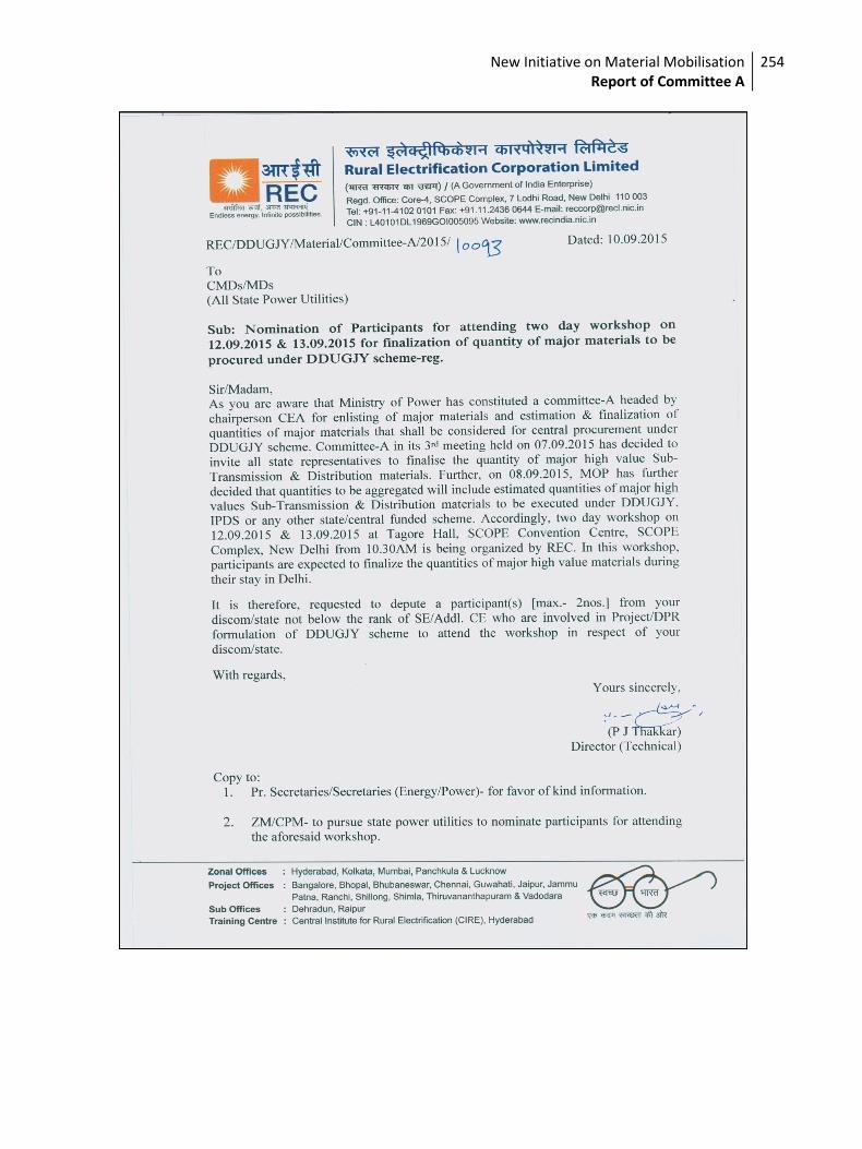
New Initiative on Material Mobilisation Report of Committee A
254
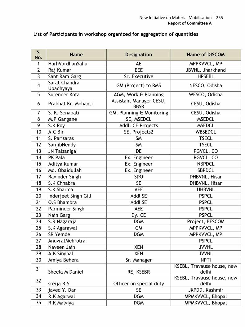
New Initiative on Material Mobilisation Report of Committee A
255
List of Participants in workshop organized for aggregation of quantities
S. No.
Name Designation Name of DISCOM
1 HarhVardhanSahu AE MPPKVVCL, MP
2 Raj Kumar EEE JBVNL, Jharkhand
3 Sant Ram Garg Sr. Executive HPSEBL
4 Sarat Chandra Upadhyaya
GM (Project) to RMS NESCO, Odisha
5 Surender Kota AGM, Work & Planning WESCO, Odisha
6 Prabhat Kr. Mohanti Assistant Manager CESU,
BBSR CESU, Odisha
7 S. K. Senapati GM, Planning & Monitoring CESU, Odisha
8 M.P Gangane SE, MSEDCL MSEDCL
9 S.K Roy Addl. CE Projects MSEDCL
10 A.C Bir SE, Projects2 WBSEDCL
11 S. Parisaras SM TSECL
12 SanjibNendy SM TSECL
13 JN Talsaniga DE PGVCL, CO
14 PK Pala Ex. Engineer PGVCL, CO
15 Aditya Kumar Ex. Engineer NBPDCL
16 Md. Obaidullah Ex. Engineer SBPDCL
17 Ravinder Singh SDO DHBVNL, Hisar
18 S.K Chhabra SE DHBVNL, Hisar
19 S.K Sharma AEE UHBVNL
20 Inderjeet Singh Gill Addl SE PSPCL
21 O.S Bhambra Addl SE PSPCL
22 Parminder Singh AEE PSPCL
23 Nain Garg Dy. CE PSPCL
24 S.R Nagaraja DGM Project, BESCOM
25 S.K Agarawal GM MPPKVVCL, MP
26 SR Yemde DGM MPPKVVCL, MP
27 AnuvratMehrotra PSPCL
28 Naveen Jain XEN JVVNL
29 A.K Singhal XEN JVVNL
30 Amiya Behera Sr. Manager NPTI
31 Sheela M Daniel RE, KSEBR
KSEBL, Travause house, new delhi
32 sreija R.S Officer on special duty
KSEBL, Travause house, new delhi
33 javed Y. Dar SE JKPDD, Kashmir
34 R.K Agarwal DGM MPMKVVCL, Bhopal
35 R.K Malviya DGM MPMKVVCL, Bhopal
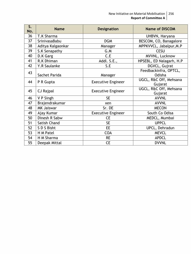
New Initiative on Material Mobilisation Report of Committee A
256
S. No.
Name Designation Name of DISCOM
36 T.K Sharma UHBVN, Haryana
37 SrinivasaBabu DGM BESCOM, CO, Banagalore
38 Aditya Kalgaonkar Manager MPPKVVCL, Jabalpur,M.P
39 S.K Senapathy G.M CESU
40 D.K Garg C.E MVVNL, Lucknow
41 R.K Dhiman Addl. S.E., HPSEBL, ED Nalagarh, H.P
42 Y.R Saulanke S.E DGVCL, Gujrat
43 Sachet Parida Manager
Feedbackinfra, OPTCL, Odisha
44 P R Gupta Executive Engineer UGCL, R&C Off, Mehsana
Gujarat
45 CJ Rajpal Executive Engineer UGCL, R&C Off, Mehsana
Gujarat
46 V P Singh SE AVVNL
47 Brajendrakumar xen AVVNL
48 MK Jaiswar Sr. DE MECON
49 Ajay Kumar Executive Engineer South Co Odisa
50 Dinesh R Sabw CE MEDCL, Mumbai
51 Satish Chand SE UPPCL
52 S D S Bisht EE UPCL, Dehradun
53 H M Patel COA MEVCL
54 H M Sharma RE APDCL
55 Deepak Mittal CE DVVNL
New Initiative on Material Mobilisation Report of Committee A
257
Annexure-VII
Aggregate Quantity
under
DDUGJY& IPDS Schemes
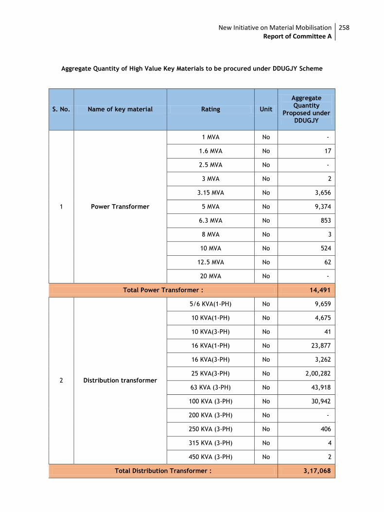
New Initiative on Material Mobilisation Report of Committee A
258
Aggregate Quantity of High Value Key Materials to be procured under DDUGJY Scheme
S. No. Name of key material Rating Unit
Aggregate Quantity
Proposed under DDUGJY
1 Power Transformer
1 MVA No -
1.6 MVA No 17
2.5 MVA No -
3 MVA No 2
3.15 MVA No 3,656
5 MVA No 9,374
6.3 MVA No 853
8 MVA No 3
10 MVA No 524
12.5 MVA No 62
20 MVA No -
Total Power Transformer : 14,491
2 Distribution transformer
5/6 KVA(1-PH) No 9,659
10 KVA(1-PH) No 4,675
10 KVA(3-PH) No 41
16 KVA(1-PH) No 23,877
16 KVA(3-PH) No 3,262
25 KVA(3-PH) No 2,00,282
63 KVA (3-PH) No 43,918
100 KVA (3-PH) No 30,942
200 KVA (3-PH) No -
250 KVA (3-PH) No 406
315 KVA (3-PH) No 4
450 KVA (3-PH) No 2
Total Distribution Transformer : 3,17,068
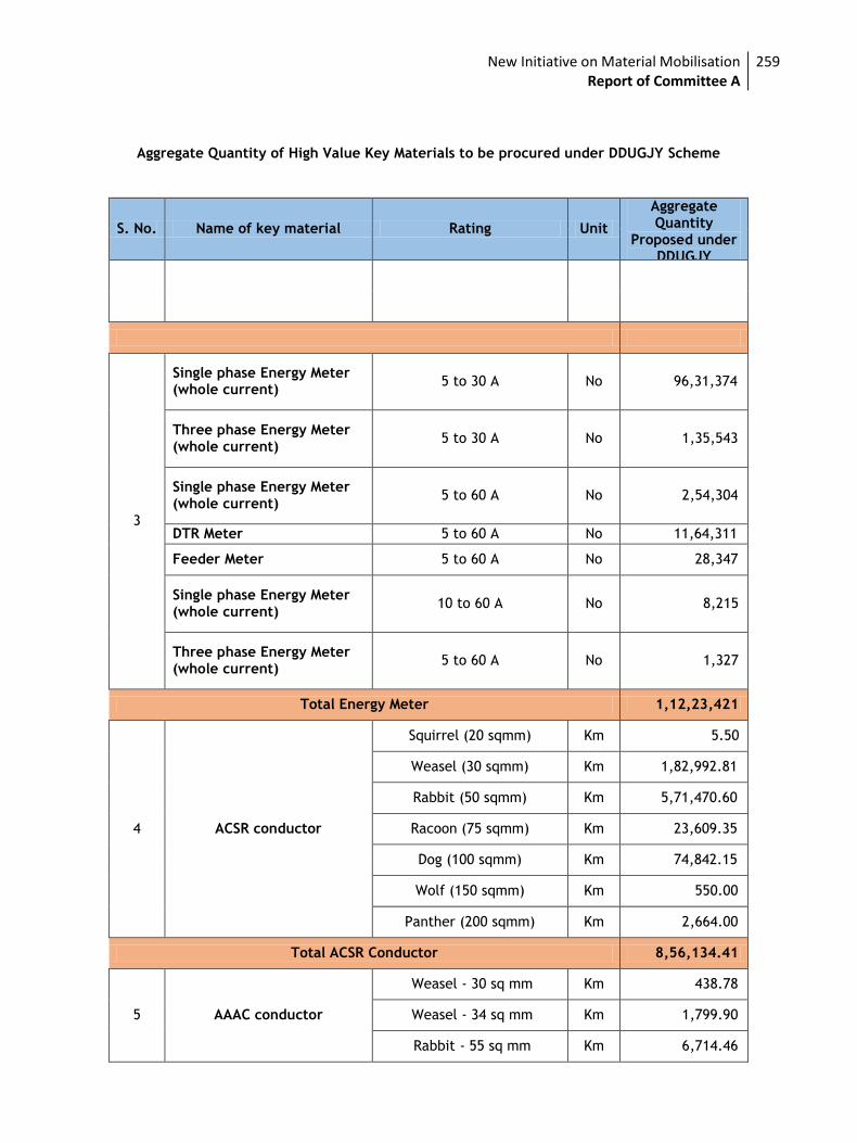
New Initiative on Material Mobilisation Report of Committee A
259
Aggregate Quantity of High Value Key Materials to be procured under DDUGJY Scheme
S. No. Name of key material Rating Unit
Aggregate Quantity
Proposed under DDUGJY
Single phase Energy Meter (whole current)
5 to 30 A No 96,31,374
Three phase Energy Meter (whole current)
5 to 30 A No 1,35,543
Single phase Energy Meter (whole current)
5 to 60 A No 2,54,304
DTR Meter 5 to 60 A No 11,64,311
Feeder Meter 5 to 60 A No 28,347
Single phase Energy Meter (whole current)
10 to 60 A No 8,215
Three phase Energy Meter (whole current)
5 to 60 A No 1,327
Total Energy Meter 1,12,23,421
4 ACSR conductor
Squirrel (20 sqmm) Km 5.50
Weasel (30 sqmm) Km 1,82,992.81
Rabbit (50 sqmm) Km 5,71,470.60
Racoon (75 sqmm) Km 23,609.35
Dog (100 sqmm) Km 74,842.15
Wolf (150 sqmm) Km 550.00
Panther (200 sqmm) Km 2,664.00
Total ACSR Conductor 8,56,134.41
5 AAAC conductor
Weasel - 30 sq mm Km 438.78
Weasel - 34 sq mm Km 1,799.90
Rabbit - 55 sq mm Km 6,714.46
3
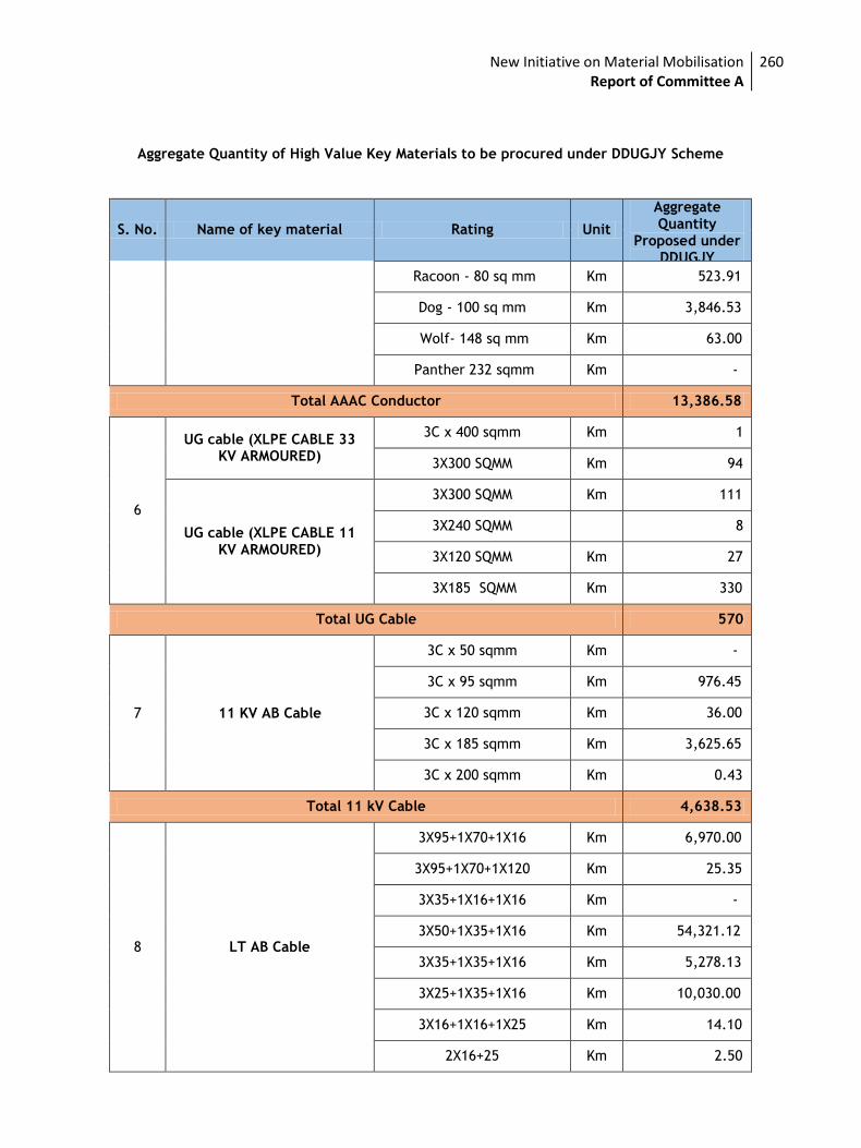
New Initiative on Material Mobilisation Report of Committee A
260
Aggregate Quantity of High Value Key Materials to be procured under DDUGJY Scheme
S. No. Name of key material Rating Unit
Aggregate Quantity
Proposed under DDUGJY
Racoon - 80 sq mm Km 523.91
Dog - 100 sq mm Km 3,846.53
Wolf- 148 sq mm Km 63.00
Panther 232 sqmm Km -
Total AAAC Conductor 13,386.58
6
UG cable (XLPE CABLE 33 KV ARMOURED)
3C x 400 sqmm Km 1
3X300 SQMM Km 94
UG cable (XLPE CABLE 11 KV ARMOURED)
3X300 SQMM Km 111
3X240 SQMM 8
3X120 SQMM Km 27
3X185 SQMM Km 330
Total UG Cable 570
3C x 50 sqmm Km -
3C x 95 sqmm Km 976.45
3C x 120 sqmm Km 36.00
3C x 185 sqmm Km 3,625.65
3C x 200 sqmm Km 0.43
Total 11 kV Cable 4,638.53
3X95+1X70+1X16 Km 6,970.00
3X95+1X70+1X120 Km 25.35
3X35+1X16+1X16 Km -
3X50+1X35+1X16 Km 54,321.12
3X35+1X35+1X16 Km 5,278.13
3X25+1X35+1X16 Km 10,030.00
3X16+1X16+1X25 Km 14.10
2X16+25 Km 2.50
7 11 KV AB Cable
8 LT AB Cable
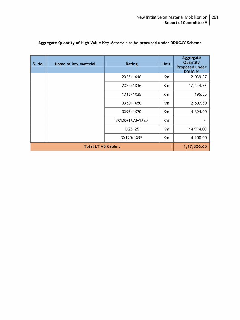
New Initiative on Material Mobilisation Report of Committee A
261
Aggregate Quantity of High Value Key Materials to be procured under DDUGJY Scheme
S. No. Name of key material Rating Unit
Aggregate Quantity
Proposed under DDUGJY
2X35+1X16 Km 2,039.37
2X25+1X16 Km 12,454.73
1X16+1X25 Km 195.55
3X50+1X50 Km 2,507.80
3X95+1X70 Km 4,394.00
3X120+1X70+1X25 km -
1X25+25 Km 14,994.00
3X120+1X95 Km 4,100.00
Total LT AB Cable : 1,17,326.65
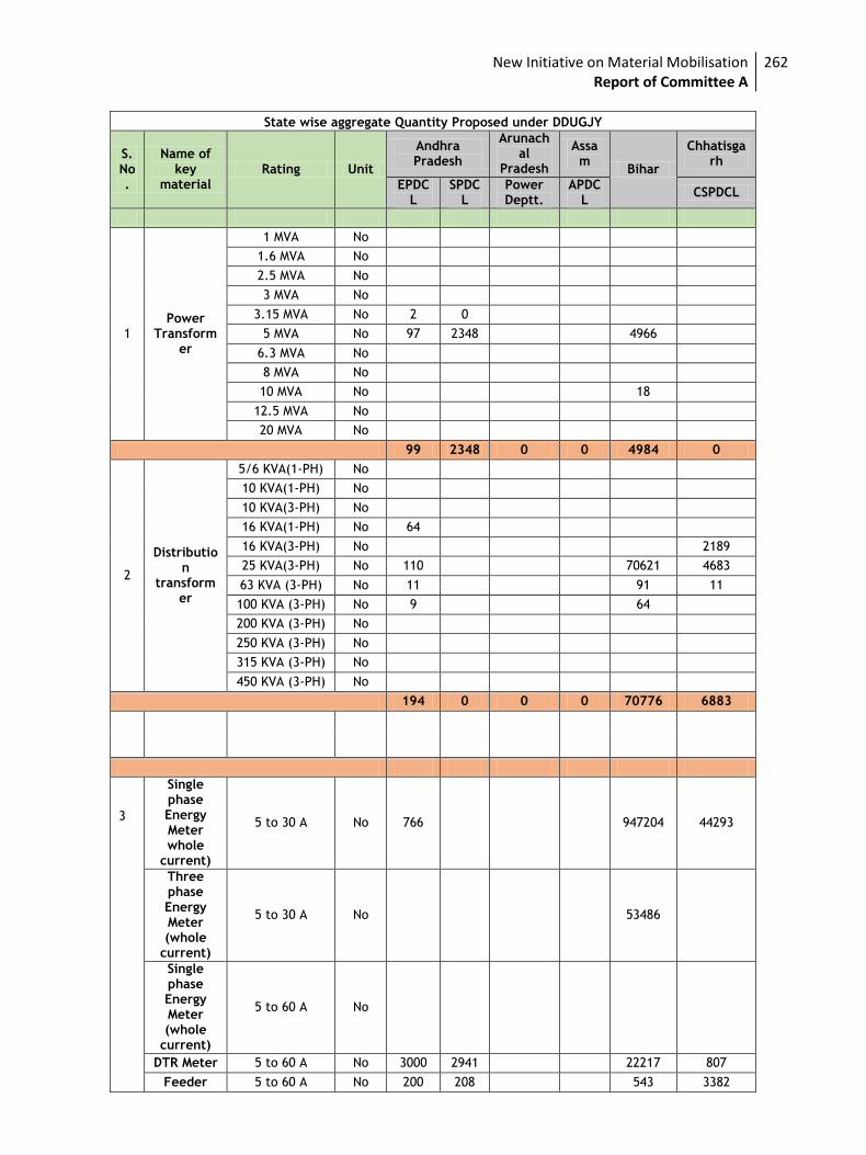
New Initiative on Material Mobilisation Report of Committee A
262
State wise aggregate Quantity Proposed under DDUGJY
S. No.
Name of key
material Rating Unit
Andhra Pradesh
Arunachal
Pradesh
Assam
Bihar
Chhatisgarh
EPDCL
SPDCL
Power Deptt.
APDCL
CSPDCL
1 Power
Transformer
1 MVA No
1.6 MVA No
2.5 MVA No
3 MVA No
3.15 MVA No 2 0
5 MVA No 97 2348 4966
6.3 MVA No
8 MVA No
10 MVA No 18
12.5 MVA No
20 MVA No
99 2348 0 0 4984 0
2
Distribution
transformer
5/6 KVA(1-PH) No
10 KVA(1-PH) No
10 KVA(3-PH) No
16 KVA(1-PH) No 64
16 KVA(3-PH) No 2189
25 KVA(3-PH) No 110 70621 4683
63 KVA (3-PH) No 11 91 11
100 KVA (3-PH) No 9 64
200 KVA (3-PH) No
250 KVA (3-PH) No
315 KVA (3-PH) No
450 KVA (3-PH) No
194 0 0 0 70776 6883
Single phase Energy Meter whole
current)
5 to 30 A No 766 947204 44293
Three phase Energy Meter (whole
current)
5 to 30 A No 53486
Single phase Energy Meter (whole
current)
5 to 60 A No
DTR Meter 5 to 60 A No 3000 2941 22217 807
Feeder 5 to 60 A No 200 208 543 3382
3
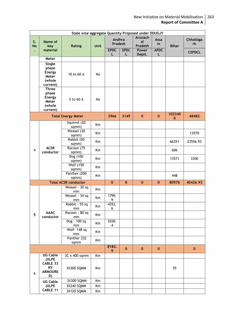
New Initiative on Material Mobilisation Report of Committee A
263
State wise aggregate Quantity Proposed under DDUGJY
S. No.
Name of key
material Rating Unit
Andhra Pradesh
Arunachal
Pradesh
Assam
Bihar
Chhatisgarh
EPDCL
SPDCL
Power Deptt.
APDCL
CSPDCL
Meter
Single phase Energy Meter (whole
current)
10 to 60 A No
Three phase Energy Meter (whole
current)
5 to 60 A No
Total Energy Meter 3966 3149 0 0 102345
0 48482
4 ACSR
conductor
Squirrel (20 sqmm)
Km
Weasel (30 sqmm)
Km 13570
Rabbit (50 sqmm)
Km 66351 23556.93
Racoon (75 sqmm)
Km 606
Dog (100 sqmm)
Km 13571 3300
Wolf (150 sqmm)
Km
Panther (200 sqmm)
Km 448
Total ACSR conductor 0 0 0 0 80976 40426.93
5 AAAC
conductor
Weasel - 30 sq mm
Km
Weasel - 34 sq mm
Km 1799.
9
Rabbit - 55 sq mm
Km 4352.
6
Racoon - 80 sq mm
Km
Dog - 100 sq mm
Km 2030.
4
Wolf- 148 sq mm
Km
Panther 232 sqmm
Km
8182.
9 0 0 0 0
6
UG Cable (XLPE
CABLE 33 KV
ARMOURED)
3C x 400 sqmm Km
3X300 SQMM Km 55
UG Cable (XLPE
CABLE 11
3X300 SQMM Km
3X240 SQMM Km
3X120 SQMM Km
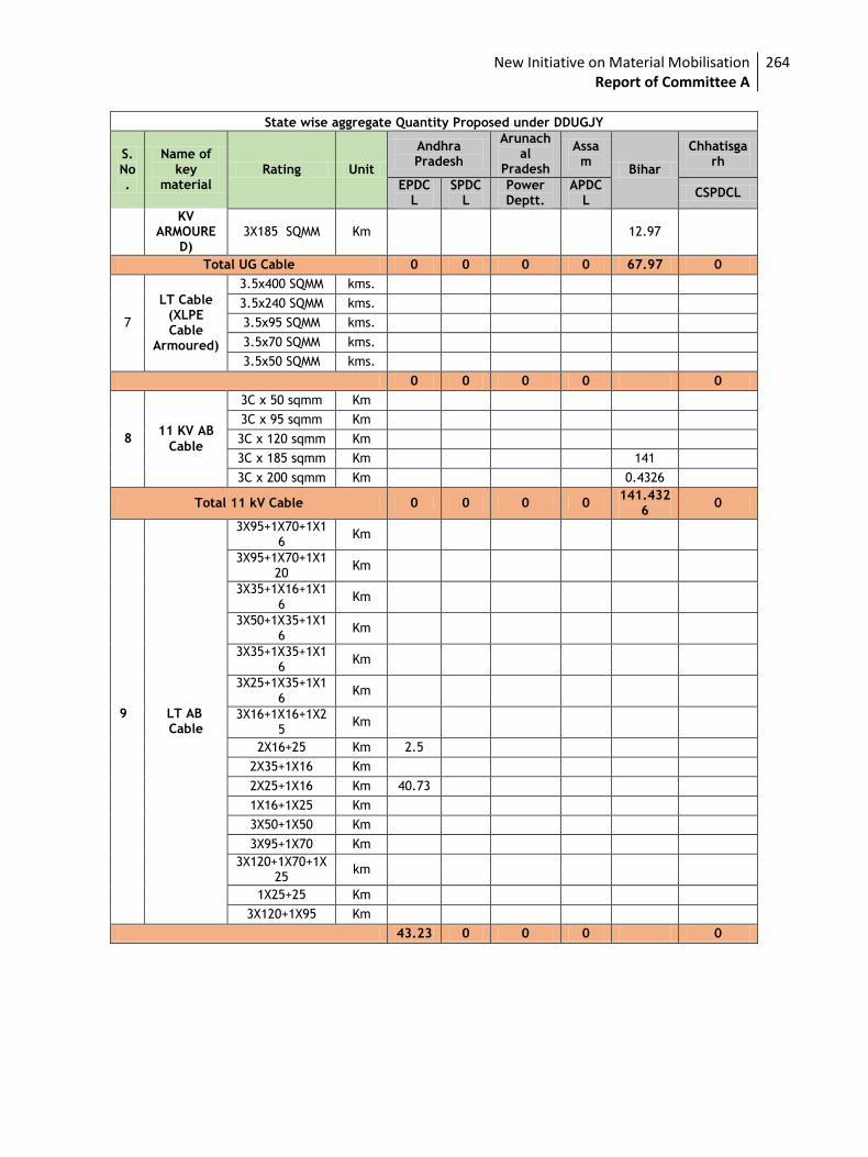
New Initiative on Material Mobilisation Report of Committee A
264
State wise aggregate Quantity Proposed under DDUGJY
S. No.
Name of key
material Rating Unit
Andhra Pradesh
Arunachal
Pradesh
Assam
Bihar
Chhatisgarh
EPDCL
SPDCL
Power Deptt.
APDCL
CSPDCL
KV ARMOURE
D) 3X185 SQMM Km 12.97
Total UG Cable 0 0 0 0 67.97 0
7
LT Cable (XLPE Cable
Armoured)
3.5x400 SQMM kms.
3.5x240 SQMM kms.
3.5x95 SQMM kms.
3.5x70 SQMM kms.
3.5x50 SQMM kms.
0 0 0 0 0
Cable
3C x 50 sqmm Km
3C x 95 sqmm Km
3C x 120 sqmm Km
3C x 185 sqmm Km 141
3C x 200 sqmm Km 0.4326
Total 11 kV Cable 0 0 0 0 141.432
6 0
Cable
3X95+1X70+1X16
Km
3X95+1X70+1X120
Km
3X35+1X16+1X16
Km
3X50+1X35+1X16
Km
3X35+1X35+1X16
Km
3X25+1X35+1X16
Km
3X16+1X16+1X25
Km
2X16+25 Km 2.5
2X35+1X16 Km
2X25+1X16 Km 40.73
1X16+1X25 Km
3X50+1X50 Km
3X95+1X70 Km
3X120+1X70+1X25
km
1X25+25 Km
3X120+1X95 Km
43.23 0 0 0 0
11 KV AB 8
9 LT AB
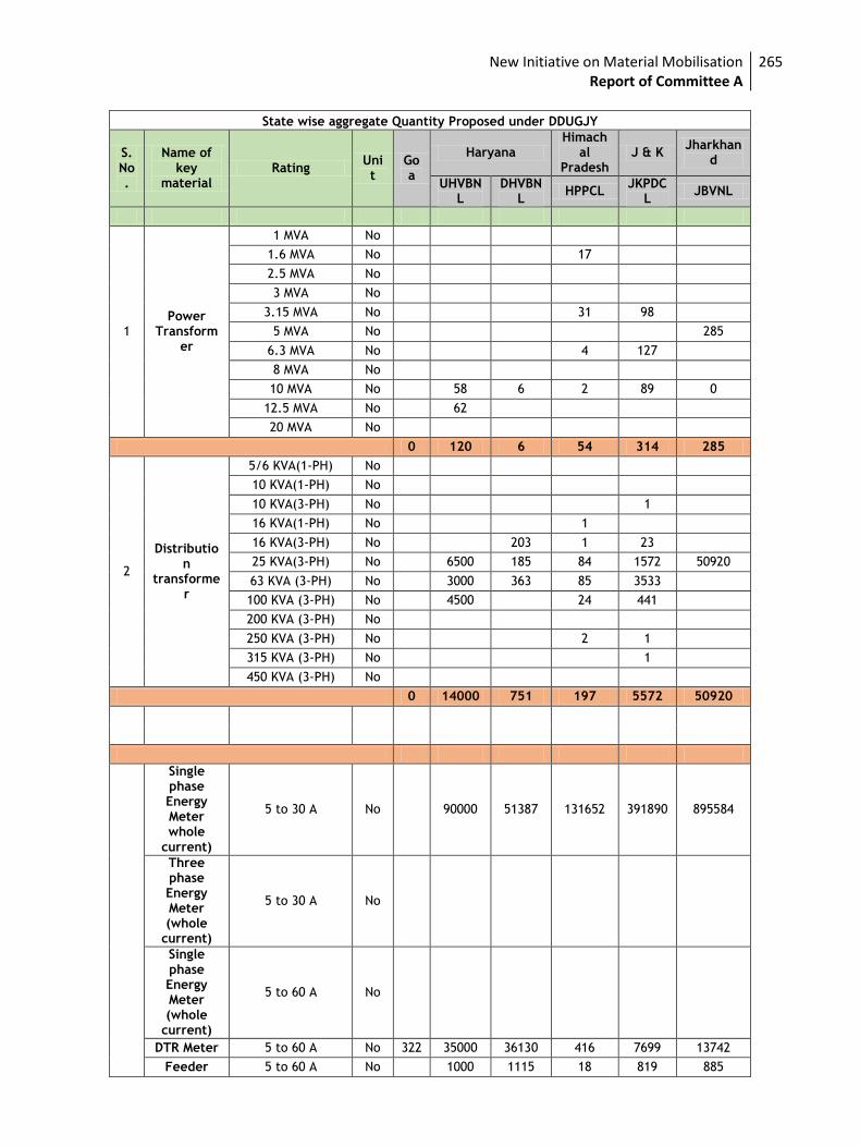
New Initiative on Material Mobilisation Report of Committee A
265
State wise aggregate Quantity Proposed under DDUGJY
S. No.
Name of key
material Rating
Unit
Goa
Haryana Himach
al Pradesh
J & K Jharkhan
d
UHVBNL
DHVBNL
HPPCL JKPDC
L JBVNL
1 Power
Transformer
1 MVA No
1.6 MVA No 17
2.5 MVA No
3 MVA No
3.15 MVA No 31 98
5 MVA No 285
6.3 MVA No 4 127
8 MVA No
10 MVA No 58 6 2 89 0
12.5 MVA No 62
20 MVA No
0 120 6 54 314 285
2
Distribution
transformer
5/6 KVA(1-PH) No
10 KVA(1-PH) No
10 KVA(3-PH) No 1
16 KVA(1-PH) No 1
16 KVA(3-PH) No 203 1 23
25 KVA(3-PH) No 6500 185 84 1572 50920
63 KVA (3-PH) No 3000 363 85 3533
100 KVA (3-PH) No 4500 24 441
200 KVA (3-PH) No
250 KVA (3-PH) No 2 1
315 KVA (3-PH) No 1
450 KVA (3-PH) No
0 14000 751 197 5572 50920
Single phase Energy Meter whole
current)
5 to 30 A No 90000 51387 131652 391890 895584
Three phase Energy Meter (whole
current)
5 to 30 A No
Single phase Energy Meter (whole
current)
5 to 60 A No
DTR Meter 5 to 60 A No 322 35000 36130 416 7699 13742
Feeder 5 to 60 A No 1000 1115 18 819 885
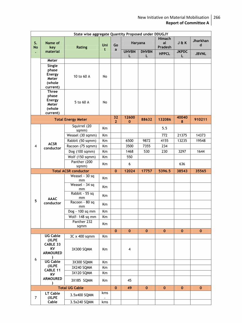
New Initiative on Material Mobilisation Report of Committee A
266
State wise aggregate Quantity Proposed under DDUGJY
S. No.
Name of key
material Rating
Unit
Goa
Haryana Himach
al Pradesh
J & K Jharkhan
d
UHVBNL
DHVBNL
HPPCL JKPDC
L JBVNL
Meter
Single phase Energy Meter (whole
current)
10 to 60 A No
Three phase Energy Meter (whole
current)
5 to 60 A No
Total Energy Meter 322
126000
88632 132086 40040
8 910211
4 ACSR
conductor
Squirrel (20 sqmm)
Km 5.5
Weasel (30 sqmm) Km 772 21375 14373
Rabbit (50 sqmm) Km 6500 9872 4155 13235 19548
Racoon (75 sqmm) Km 3500 7355 234
Dog (100 sqmm) Km 1468 530 230 3297 1644
Wolf (150 sqmm) Km 550
Panther (200 sqmm)
Km 6 636
Total ACSR conductor 0 12024 17757 5396.5 38543 35565
5 AAAC
conductor
Weasel - 30 sq mm
Km
Weasel - 34 sq mm
Km
Rabbit - 55 sq mm
Km
Racoon - 80 sq mm
Km
Dog - 100 sq mm Km
Wolf- 148 sq mm Km
Panther 232 sqmm
Km
0 0 0 0 0 0
6
UG Cable (XLPE
CABLE 33 KV
ARMOURED)
3C x 400 sqmm Km
3X300 SQMM Km 4
UG Cable (XLPE
CABLE 11 KV
ARMOURED)
3X300 SQMM Km
3X240 SQMM Km
3X120 SQMM Km
3X185 SQMM Km 45
Total UG Cable 0 49 0 0 0 0
7 LT Cable
(XLPE Cable
3.5x400 SQMM kms
.
3.5x240 SQMM kms
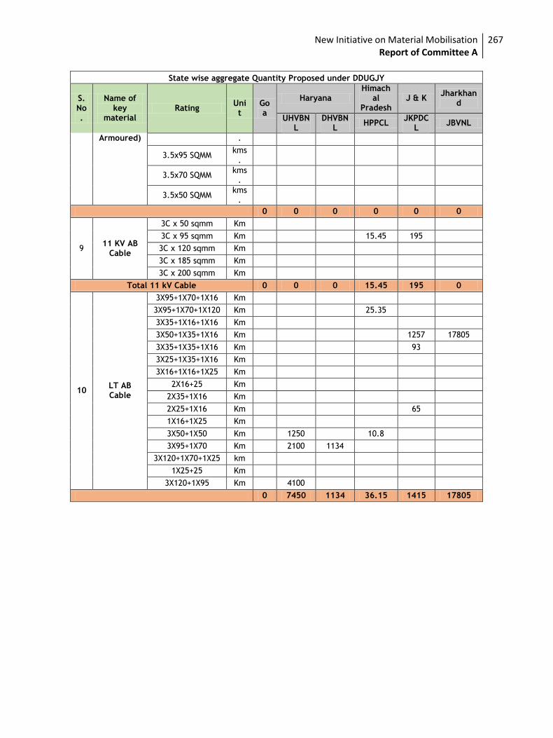
New Initiative on Material Mobilisation Report of Committee A
267
State wise aggregate Quantity Proposed under DDUGJY
S. No.
Name of key
material Rating
Unit
Goa
Haryana Himach
al Pradesh
J & K Jharkhan
d
UHVBNL
DHVBNL
HPPCL JKPDC
L JBVNL
Armoured) .
3.5x95 SQMM kms
.
3.5x70 SQMM kms
.
3.5x50 SQMM kms
.
0 0 0 0 0 0
9 11 KV AB
Cable
3C x 50 sqmm Km
3C x 95 sqmm Km 15.45 195
3C x 120 sqmm Km
3C x 185 sqmm Km
3C x 200 sqmm Km
Total 11 kV Cable 0 0 0 15.45 195 0
10 LT AB Cable
3X95+1X70+1X16 Km
3X95+1X70+1X120 Km 25.35
3X35+1X16+1X16 Km
3X50+1X35+1X16 Km 1257 17805
3X35+1X35+1X16 Km 93
3X25+1X35+1X16 Km
3X16+1X16+1X25 Km
2X16+25 Km
2X35+1X16 Km
2X25+1X16 Km 65
1X16+1X25 Km
3X50+1X50 Km 1250 10.8
3X95+1X70 Km 2100 1134
3X120+1X70+1X25 km
1X25+25 Km
3X120+1X95 Km 4100
0 7450 1134 36.15 1415 17805
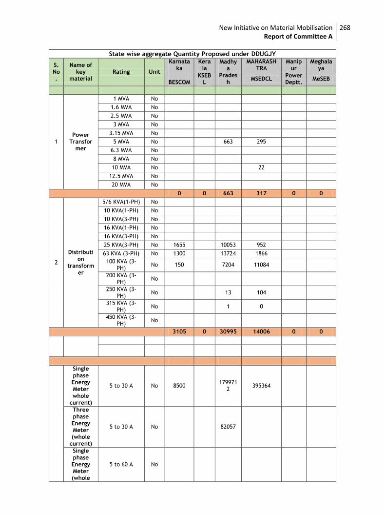
New Initiative on Material Mobilisation Report of Committee A
268
State wise aggregate Quantity Proposed under DDUGJY
S. No.
Name of key
material Rating Unit
Karnataka
Kerala
Madhya
Pradesh
MAHARASHTRA
Manipur
Meghalaya
BESCOM
KSEBL
MSEDCL Power Deptt.
MeSEB
1 Power
Transformer
1 MVA No
1.6 MVA No
2.5 MVA No
3 MVA No
3.15 MVA No
5 MVA No 663 295
6.3 MVA No
8 MVA No
10 MVA No 22
12.5 MVA No
20 MVA No
0 0 663 317 0 0
2
Distribution
transformer
5/6 KVA(1-PH) No
10 KVA(1-PH) No
10 KVA(3-PH) No
16 KVA(1-PH) No
16 KVA(3-PH) No
25 KVA(3-PH) No 1655 10053 952
63 KVA (3-PH) No 1300 13724 1866
100 KVA (3-PH)
No 150 7204 11084
200 KVA (3-PH)
No
250 KVA (3-PH)
No 13 104
315 KVA (3-PH)
No 1 0
450 KVA (3-PH)
No
3105 0 30995 14006 0 0
Single phase Energy Meter whole
current)
5 to 30 A No 8500 179971
2 395364
Three phase Energy Meter (whole
current)
5 to 30 A No 82057
Single phase Energy Meter (whole
5 to 60 A No
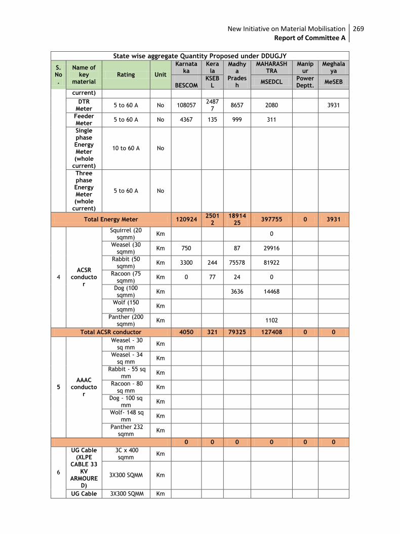
New Initiative on Material Mobilisation Report of Committee A
269
State wise aggregate Quantity Proposed under DDUGJY
S. No.
Name of key
material Rating Unit
Karnataka
Kerala
Madhya
Pradesh
MAHARASHTRA
Manipur
Meghalaya
BESCOM
KSEBL
MSEDCL Power Deptt.
MeSEB
current)
DTR Meter
5 to 60 A No 108057 2487
7 8657 2080 3931
Feeder Meter
5 to 60 A No 4367 135 999 311
Single phase Energy Meter (whole
current)
10 to 60 A No
Three phase Energy Meter (whole
current)
5 to 60 A No
Total Energy Meter 120924 2501
2 18914
25 397755 0 3931
4 ACSR
conductor
Squirrel (20 sqmm)
Km 0
Weasel (30 sqmm)
Km 750 87 29916
Rabbit (50 sqmm)
Km 3300 244 75578 81922
Racoon (75 sqmm)
Km 0 77 24 0
Dog (100 sqmm)
Km 3636 14468
Wolf (150 sqmm)
Km
Panther (200 sqmm)
Km 1102
Total ACSR conductor 4050 321 79325 127408 0 0
5 AAAC
conductor
Weasel - 30 sq mm
Km
Weasel - 34 sq mm
Km
Rabbit - 55 sq mm
Km
Racoon - 80 sq mm
Km
Dog - 100 sq mm
Km
Wolf- 148 sq mm
Km
Panther 232 sqmm
Km
0 0 0 0 0 0
6
UG Cable (XLPE
CABLE 33 KV
ARMOURED)
3C x 400 sqmm
Km
3X300 SQMM Km
UG Cable 3X300 SQMM Km
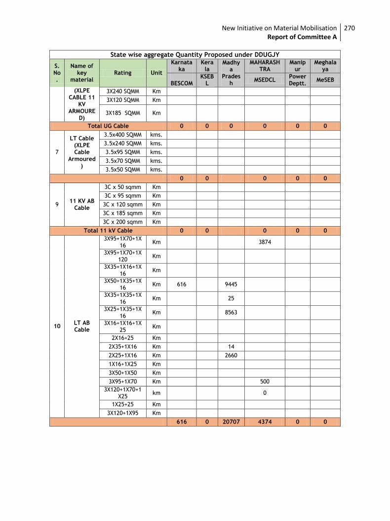
New Initiative on Material Mobilisation Report of Committee A
270
State wise aggregate Quantity Proposed under DDUGJY
S. No.
Name of key
material Rating Unit
Karnataka
Kerala
Madhya
Pradesh
MAHARASHTRA
Manipur
Meghalaya
BESCOM
KSEBL
MSEDCL Power Deptt.
MeSEB
(XLPE CABLE 11
KV ARMOURE
D)
3X240 SQMM Km
3X120 SQMM Km
3X185 SQMM Km
Total UG Cable 0 0 0 0 0 0
7
LT Cable (XLPE Cable
Armoured)
3.5x400 SQMM kms.
3.5x240 SQMM kms.
3.5x95 SQMM kms.
3.5x70 SQMM kms.
3.5x50 SQMM kms.
0 0 0 0 0
9 11 KV AB
Cable
3C x 50 sqmm Km
3C x 95 sqmm Km
3C x 120 sqmm Km
3C x 185 sqmm Km
3C x 200 sqmm Km
Total 11 kV Cable 0 0 0 0 0
10 LT AB Cable
3X95+1X70+1X16
Km 3874
3X95+1X70+1X120
Km
3X35+1X16+1X16
Km
3X50+1X35+1X16
Km 616 9445
3X35+1X35+1X16
Km 25
3X25+1X35+1X16
Km 8563
3X16+1X16+1X25
Km
2X16+25 Km
2X35+1X16 Km 14
2X25+1X16 Km 2660
1X16+1X25 Km
3X50+1X50 Km
3X95+1X70 Km 500
3X120+1X70+1X25
km 0
1X25+25 Km
3X120+1X95 Km
616 0 20707 4374 0 0
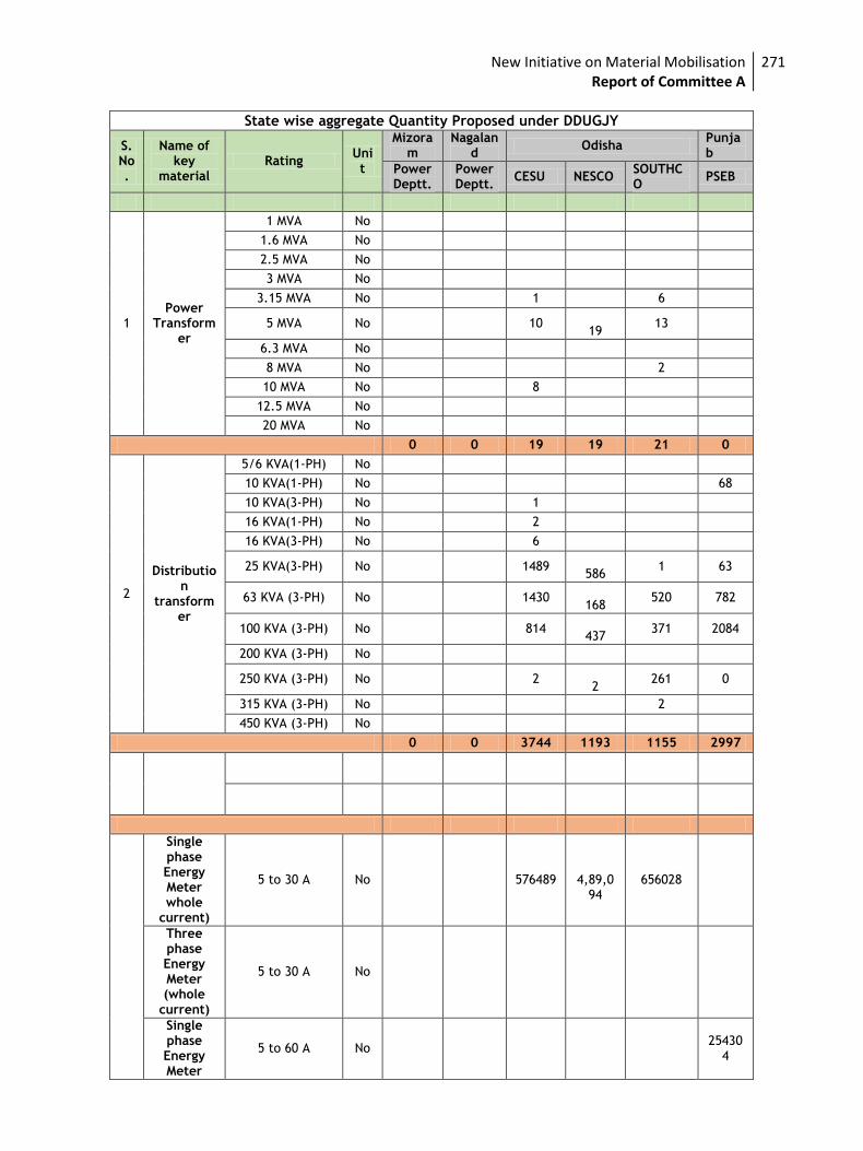
New Initiative on Material Mobilisation Report of Committee A
271
State wise aggregate Quantity Proposed under DDUGJY
S. No.
Name of key
material Rating
Unit
Mizoram
Nagaland
Odisha Punjab
Power Deptt.
Power Deptt.
CESU NESCO SOUTHCO
PSEB
1 Power
Transformer
1 MVA No
1.6 MVA No
2.5 MVA No
3 MVA No
3.15 MVA No 1 6
5 MVA No 10
19 13
6.3 MVA No
8 MVA No 2
10 MVA No 8
12.5 MVA No
20 MVA No
0 0 19 19 21 0
2
Distribution
transformer
5/6 KVA(1-PH) No
10 KVA(1-PH) No 68
10 KVA(3-PH) No 1
16 KVA(1-PH) No 2
16 KVA(3-PH) No 6
25 KVA(3-PH) No 1489
586 1 63
63 KVA (3-PH) No 1430
168 520 782
100 KVA (3-PH) No 814
437 371 2084
200 KVA (3-PH) No
250 KVA (3-PH) No 2 2
261 0
315 KVA (3-PH) No 2
450 KVA (3-PH) No
0 0 3744 1193 1155 2997
Single phase Energy Meter whole
current)
5 to 30 A No 576489
4,89,094
656028
Three phase Energy Meter (whole
current)
5 to 30 A No
Single phase Energy Meter
5 to 60 A No 25430
4
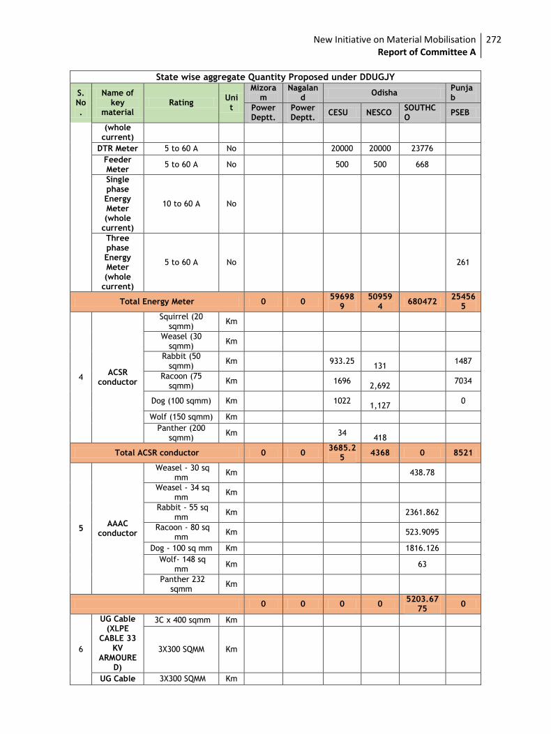
New Initiative on Material Mobilisation Report of Committee A
272
State wise aggregate Quantity Proposed under DDUGJY
S. No.
Name of key
material Rating
Unit
Mizoram
Nagaland
Odisha Punjab
Power Deptt.
Power Deptt.
CESU NESCO SOUTHCO
PSEB
(whole current)
DTR Meter 5 to 60 A No 20000 20000 23776
Feeder Meter
5 to 60 A No 500 500 668
Single phase Energy Meter (whole
current)
10 to 60 A No
Three phase Energy Meter (whole
current)
5 to 60 A No 261
Total Energy Meter 0 0 59698
9 50959
4 680472
254565
4 ACSR
conductor
Squirrel (20 sqmm)
Km
Weasel (30 sqmm)
Km
Rabbit (50 sqmm)
Km 933.25
131 1487
Racoon (75 sqmm)
Km 1696
2,692 7034
Dog (100 sqmm) Km 1022
1,127 0
Wolf (150 sqmm) Km
Panther (200 sqmm)
Km 34
418
Total ACSR conductor 0 0 3685.2
5 4368 0 8521
5 AAAC
conductor
Weasel - 30 sq mm
Km 438.78
Weasel - 34 sq mm
Km
Rabbit - 55 sq mm
Km 2361.862
Racoon - 80 sq mm
Km 523.9095
Dog - 100 sq mm Km 1816.126
Wolf- 148 sq mm
Km 63
Panther 232 sqmm
Km
0 0 0 0 5203.67
75 0
6
UG Cable (XLPE
CABLE 33 KV
ARMOURED)
3C x 400 sqmm Km
3X300 SQMM Km
UG Cable 3X300 SQMM Km
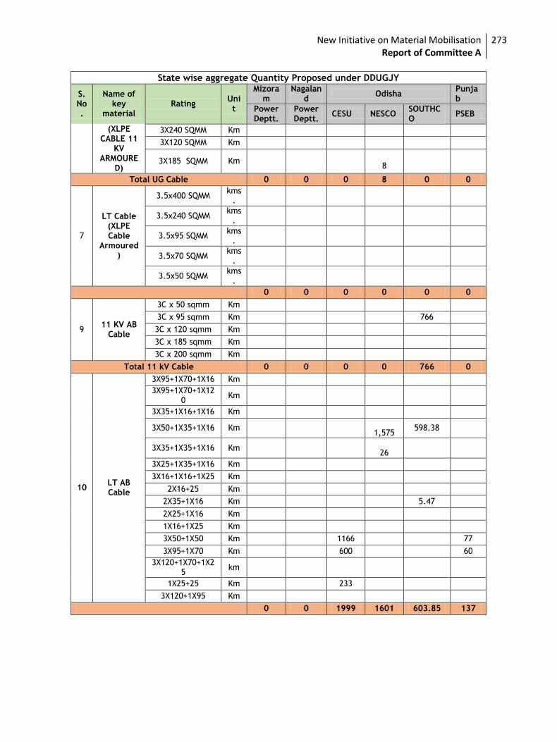
New Initiative on Material Mobilisation Report of Committee A
273
State wise aggregate Quantity Proposed under DDUGJY
S. No.
Name of key
material Rating
Unit
Mizoram
Nagaland
Odisha Punjab
Power Deptt.
Power Deptt.
CESU NESCO SOUTHCO
PSEB
(XLPE CABLE 11
KV ARMOURE
D)
3X240 SQMM Km
3X120 SQMM Km
3X185 SQMM Km 8
Total UG Cable 0 0 0 8 0 0
7
LT Cable (XLPE Cable
Armoured)
3.5x400 SQMM kms
.
3.5x240 SQMM kms
.
3.5x95 SQMM kms
.
3.5x70 SQMM kms
.
3.5x50 SQMM kms
.
0 0 0 0 0 0
9 11 KV AB
Cable
3C x 50 sqmm Km
3C x 95 sqmm Km 766
3C x 120 sqmm Km
3C x 185 sqmm Km
3C x 200 sqmm Km
Total 11 kV Cable 0 0 0 0 766 0
10 LT AB Cable
3X95+1X70+1X16 Km
3X95+1X70+1X120
Km
3X35+1X16+1X16 Km
3X50+1X35+1X16 Km
1,575 598.38
3X35+1X35+1X16 Km
26
3X25+1X35+1X16 Km
3X16+1X16+1X25 Km
2X16+25 Km
2X35+1X16 Km 5.47
2X25+1X16 Km
1X16+1X25 Km
3X50+1X50 Km 1166 77
3X95+1X70 Km 600 60
3X120+1X70+1X25
km
1X25+25 Km 233
3X120+1X95 Km
0 0 1999 1601 603.85 137
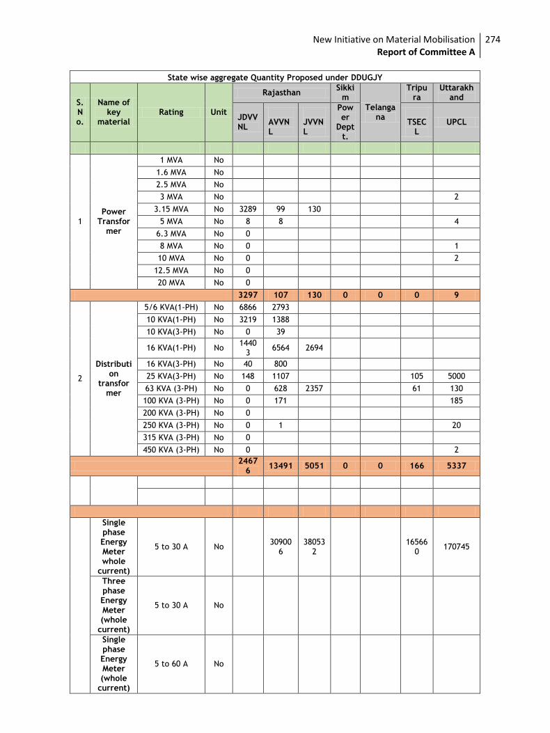
New Initiative on Material Mobilisation Report of Committee A
274
State wise aggregate Quantity Proposed under DDUGJY
S. No.
Name of key
material Rating Unit
Rajasthan Sikki
m
Telangana
Tripura
Uttarakhand
JDVVNL
AVVNL
JVVNL
Power
Deptt.
TSEC
L UPCL
1 Power
Transformer
1 MVA No
1.6 MVA No
2.5 MVA No
3 MVA No 2
3.15 MVA No 3289 99 130
5 MVA No 8 8 4
6.3 MVA No 0
8 MVA No 0 1
10 MVA No 0 2
12.5 MVA No 0
20 MVA No 0
3297 107 130 0 0 0 9
2
Distribution
transformer
5/6 KVA(1-PH) No 6866 2793
10 KVA(1-PH) No 3219 1388
10 KVA(3-PH) No 0 39
16 KVA(1-PH) No 1440
3 6564 2694
16 KVA(3-PH) No 40 800
25 KVA(3-PH) No 148 1107 105 5000
63 KVA (3-PH) No 0 628 2357 61 130
100 KVA (3-PH) No 0 171 185
200 KVA (3-PH) No 0
250 KVA (3-PH) No 0 1 20
315 KVA (3-PH) No 0
450 KVA (3-PH) No 0 2
2467
6 13491 5051 0 0 166 5337
Single phase Energy Meter whole
current)
5 to 30 A No 30900
6 38053
2
165660
170745
Three phase Energy Meter (whole
current)
5 to 30 A No
Single phase Energy Meter (whole
current)
5 to 60 A No
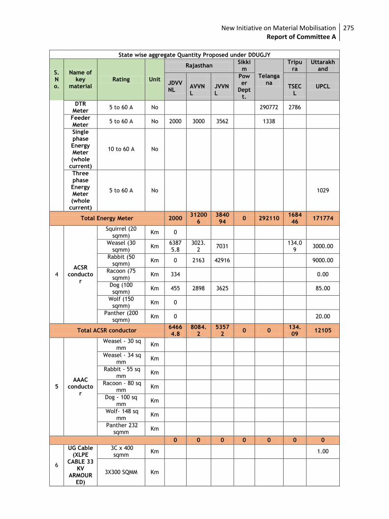
New Initiative on Material Mobilisation Report of Committee A
275
State wise aggregate Quantity Proposed under DDUGJY
S. No.
Name of key
material Rating Unit
Rajasthan Sikki
m
Telangana
Tripura
Uttarakhand
JDVVNL
AVVNL
JVVNL
Power
Deptt.
TSEC
L UPCL
DTR Meter
5 to 60 A No 290772 2786
Feeder Meter
5 to 60 A No 2000 3000 3562 1338
Single phase Energy Meter (whole
current)
10 to 60 A No
Three phase Energy Meter (whole
current)
5 to 60 A No 1029
Total Energy Meter 2000 31200
6 384094
0 292110 168446
171774
4 ACSR
conductor
Squirrel (20 sqmm)
Km 0
Weasel (30 sqmm)
Km 63875.8
3023.2
7031 134.0
9 3000.00
Rabbit (50 sqmm)
Km 0 2163 42916 9000.00
Racoon (75 sqmm)
Km 334 0.00
Dog (100 sqmm)
Km 455 2898 3625 85.00
Wolf (150 sqmm)
Km 0
Panther (200 sqmm)
Km 0 20.00
Total ACSR conductor 64664.8
8084.2
53572
0 0 134.09
12105
5 AAAC
conductor
Weasel - 30 sq mm
Km
Weasel - 34 sq mm
Km
Rabbit - 55 sq mm
Km
Racoon - 80 sq mm
Km
Dog - 100 sq mm
Km
Wolf- 148 sq mm
Km
Panther 232 sqmm
Km
0 0 0 0 0 0 0
6
UG Cable (XLPE
CABLE 33 KV
ARMOURED)
3C x 400 sqmm
Km 1.00
3X300 SQMM Km
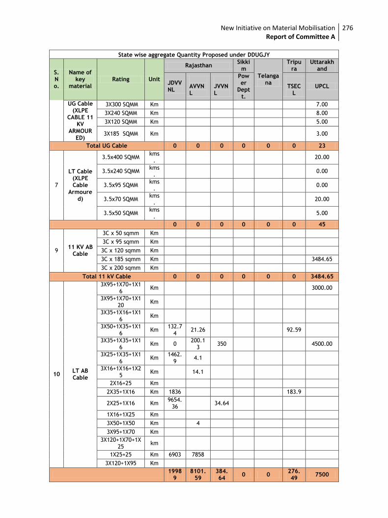
New Initiative on Material Mobilisation Report of Committee A
276
State wise aggregate Quantity Proposed under DDUGJY
S. No.
Name of key
material Rating Unit
Rajasthan Sikki
m
Telangana
Tripura
Uttarakhand
JDVVNL
AVVNL
JVVNL
Power
Deptt.
TSEC
L UPCL
UG Cable (XLPE
CABLE 11 KV
ARMOURED)
3X300 SQMM Km 7.00
3X240 SQMM Km 8.00
3X120 SQMM Km 5.00
3X185 SQMM Km 3.00
Total UG Cable 0 0 0 0 0 0 23
7
LT Cable (XLPE Cable
Armoured)
3.5x400 SQMM kms
. 20.00
3.5x240 SQMM kms
. 0.00
3.5x95 SQMM kms
. 0.00
3.5x70 SQMM kms
. 20.00
3.5x50 SQMM kms
. 5.00
0 0 0 0 0 0 45
9 11 KV AB
Cable
3C x 50 sqmm Km
3C x 95 sqmm Km
3C x 120 sqmm Km
3C x 185 sqmm Km 3484.65
3C x 200 sqmm Km
Total 11 kV Cable 0 0 0 0 0 0 3484.65
10 LT AB Cable
3X95+1X70+1X16
Km 3000.00
3X95+1X70+1X120
Km
3X35+1X16+1X16
Km
3X50+1X35+1X16
Km 132.7
4 21.26 92.59
3X35+1X35+1X16
Km 0 200.1
3 350 4500.00
3X25+1X35+1X16
Km 1462.
9 4.1
3X16+1X16+1X25
Km 14.1
2X16+25 Km
2X35+1X16 Km 1836 183.9
2X25+1X16 Km 9654.
36 34.64
1X16+1X25 Km
3X50+1X50 Km 4
3X95+1X70 Km
3X120+1X70+1X25
km
1X25+25 Km 6903 7858
3X120+1X95 Km
1998
9 8101.
59 384.64
0 0 276.49
7500
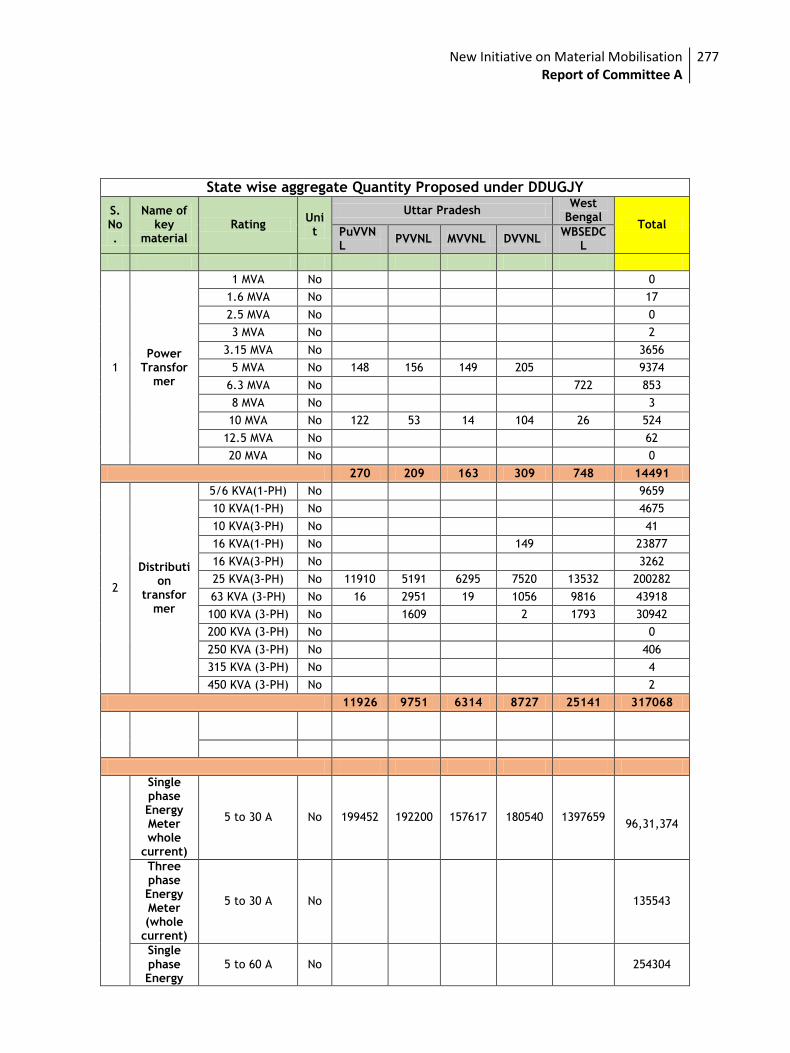
New Initiative on Material Mobilisation Report of Committee A
277
State wise aggregate Quantity Proposed under DDUGJY
S. No.
Name of key
material Rating
Unit
Uttar Pradesh West
Bengal Total
PuVVNL
PVVNL MVVNL DVVNL WBSEDC
L
1 Power
Transformer
1 MVA No 0
1.6 MVA No 17
2.5 MVA No 0
3 MVA No 2
3.15 MVA No 3656
5 MVA No 148 156 149 205 9374
6.3 MVA No 722 853
8 MVA No 3
10 MVA No 122 53 14 104 26 524
12.5 MVA No 62
20 MVA No 0
270 209 163 309 748 14491
2
Distribution
transformer
5/6 KVA(1-PH) No 9659
10 KVA(1-PH) No 4675
10 KVA(3-PH) No 41
16 KVA(1-PH) No 149 23877
16 KVA(3-PH) No 3262
25 KVA(3-PH) No 11910 5191 6295 7520 13532 200282
63 KVA (3-PH) No 16 2951 19 1056 9816 43918
100 KVA (3-PH) No 1609 2 1793 30942
200 KVA (3-PH) No 0
250 KVA (3-PH) No 406
315 KVA (3-PH) No 4
450 KVA (3-PH) No 2
11926 9751 6314 8727 25141 317068
Single phase Energy Meter whole
current)
5 to 30 A No 199452 192200 157617 180540 1397659
96,31,374
Three phase Energy Meter (whole
current)
5 to 30 A No 135543
Single phase Energy
5 to 60 A No 254304
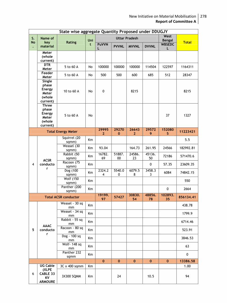
New Initiative on Material Mobilisation Report of Committee A
278
State wise aggregate Quantity Proposed under DDUGJY
S. No.
Name of key
material Rating
Unit
Uttar Pradesh West
Bengal Total
PuVVNL
PVVNL MVVNL DVVNL WBSEDC
L
Meter (whole
current)
DTR Meter
5 to 60 A No 100000 100000 100000 114504 122597 1164311
Feeder Meter
5 to 60 A No 500 500 600 685 512 28347
Single phase Energy Meter (whole
current)
10 to 60 A No 0 8215 8215
Three phase Energy Meter (whole
current)
5 to 60 A No 37 1327
Total Energy Meter 29995
2 29270
0 26643
2 29572
9 152080
5 11223421
4 ACSR
conductor
Squirrel (20 sqmm)
Km 5.5
Weasel (30 sqmm)
Km 93.04 164.73 261.95 24566 182992.81
Rabbit (50 sqmm)
Km 16782.
69 51887.
00 24586.
23 45136.
50 72186 571470.6
Racoon (75 sqmm)
Km 0 57.35 23609.35
Dog (100 sqmm)
Km 2324.2
4 5540.0
0 6079.5
8 3458.3
3 6084 74842.15
Wolf (150 sqmm)
Km 550
Panther (200 sqmm)
Km 0 2664
Total ACSR conductor 19199.
97 57427
30830.54
48856.78
102893.35
856134.41
5 AAAC
conductor
Weasel - 30 sq mm
Km 438.78
Weasel - 34 sq mm
Km 1799.9
Rabbit - 55 sq mm
Km 6714.46
Racoon - 80 sq mm
Km 523.91
Dog - 100 sq mm
Km 3846.53
Wolf- 148 sq mm
Km 63
Panther 232 sqmm
Km 0
0 0 0 0 0 13386.58
6
UG Cable (XLPE
CABLE 33 KV
ARMOURE
3C x 400 sqmm Km 1.00
3X300 SQMM Km 24 10.5 94
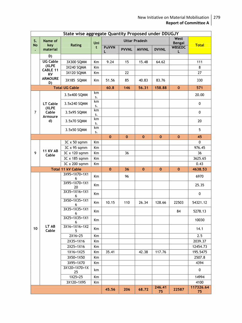
New Initiative on Material Mobilisation Report of Committee A
279
State wise aggregate Quantity Proposed under DDUGJY
S. No.
Name of key
material Rating
Unit
Uttar Pradesh West
Bengal Total
PuVVNL
PVVNL MVVNL DVVNL WBSEDC
L
D)
UG Cable (XLPE
CABLE 11 KV
ARMOURED)
3X300 SQMM Km 9.24 15 15.48 64.62 111
3X240 SQMM Km 8
3X120 SQMM Km 22 27
3X185 SQMM Km 51.56 85 40.83 83.76 330
Total UG Cable 60.8 146 56.31 158.88 0 571
7
LT Cable (XLPE Cable
Armoured)
3.5x400 SQMM kms.
20.00
3.5x240 SQMM kms.
0
3.5x95 SQMM kms.
0
3.5x70 SQMM kms.
20
3.5x50 SQMM kms.
5
0 0 0 0 0 45
9 11 KV AB
Cable
3C x 50 sqmm Km 0
3C x 95 sqmm Km 976.45
3C x 120 sqmm Km 36 36
3C x 185 sqmm Km 3625.65
3C x 200 sqmm Km 0.43
Total 11 kV Cable 0 36 0 0 0 4638.53
10 LT AB Cable
3X95+1X70+1X16
Km 96 6970
3X95+1X70+1X120
Km 25.35
3X35+1X16+1X16
Km 0
3X50+1X35+1X16
Km 10.15 110 26.34 128.66 22503 54321.12
3X35+1X35+1X16
Km 84 5278.13
3X25+1X35+1X16
Km 10030
3X16+1X16+1X25
Km 14.1
2X16+25 Km 2.5
2X35+1X16 Km 2039.37
2X25+1X16 Km 12454.73
1X16+1X25 Km 35.41 42.38 117.76 195.5475
3X50+1X50 Km 2507.8
3X95+1X70 Km 4394
3X120+1X70+1X25
km 0
1X25+25 Km 14994
3X120+1X95 Km 4100
45.56 206 68.72 246.41
75 22587
117326.6475
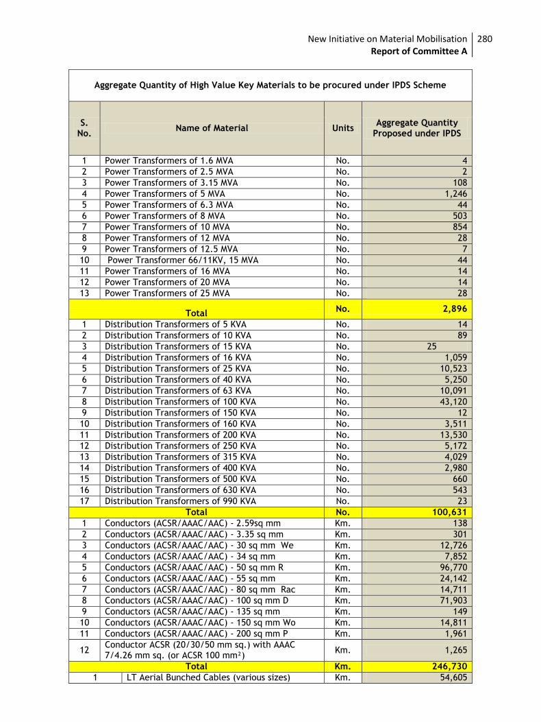
New Initiative on Material Mobilisation Report of Committee A
280
Aggregate Quantity of High Value Key Materials to be procured under IPDS Scheme
S. No.
Name of Material Units Aggregate Quantity
Proposed under IPDS
1 Power Transformers of 1.6 MVA No. 4
2 Power Transformers of 2.5 MVA No. 2
3 Power Transformers of 3.15 MVA No. 108
4 Power Transformers of 5 MVA No. 1,246
5 Power Transformers of 6.3 MVA No. 44
6 Power Transformers of 8 MVA No. 503
7 Power Transformers of 10 MVA No. 854
8 Power Transformers of 12 MVA No. 28
9 Power Transformers of 12.5 MVA No. 7
10 Power Transformer 66/11KV, 15 MVA No. 44
11 Power Transformers of 16 MVA No. 14
12 Power Transformers of 20 MVA No. 14
13 Power Transformers of 25 MVA No. 28
Total No. 2,896
1 Distribution Transformers of 5 KVA No. 14
2 Distribution Transformers of 10 KVA No. 89
3 Distribution Transformers of 15 KVA No. 25
4 Distribution Transformers of 16 KVA No. 1,059
5 Distribution Transformers of 25 KVA No. 10,523
6 Distribution Transformers of 40 KVA No. 5,250
7 Distribution Transformers of 63 KVA No. 10,091
8 Distribution Transformers of 100 KVA No. 43,120
9 Distribution Transformers of 150 KVA No. 12
10 Distribution Transformers of 160 KVA No. 3,511
11 Distribution Transformers of 200 KVA No. 13,530
12 Distribution Transformers of 250 KVA No. 5,172
13 Distribution Transformers of 315 KVA No. 4,029
14 Distribution Transformers of 400 KVA No. 2,980
15 Distribution Transformers of 500 KVA No. 660
16 Distribution Transformers of 630 KVA No. 543
17 Distribution Transformers of 990 KVA No. 23
Total No. 100,631
1 Conductors (ACSR/AAAC/AAC) - 2.59sq mm Km. 138
2 Conductors (ACSR/AAAC/AAC) - 3.35 sq mm Km. 301
3 Conductors (ACSR/AAAC/AAC) - 30 sq mm We Km. 12,726
4 Conductors (ACSR/AAAC/AAC) - 34 sq mm Km. 7,852
5 Conductors (ACSR/AAAC/AAC) - 50 sq mm R Km. 96,770
6 Conductors (ACSR/AAAC/AAC) - 55 sq mm Km. 24,142
7 Conductors (ACSR/AAAC/AAC) - 80 sq mm Rac Km. 14,711
8 Conductors (ACSR/AAAC/AAC) - 100 sq mm D Km. 71,903
9 Conductors (ACSR/AAAC/AAC) - 135 sq mm Km. 149
10 Conductors (ACSR/AAAC/AAC) - 150 sq mm Wo Km. 14,811
11 Conductors (ACSR/AAAC/AAC) - 200 sq mm P Km. 1,961
12 Conductor ACSR (20/30/50 mm sq.) with AAAC 7/4.26 mm sq. (or ACSR 100 mm²)
Km. 1,265
Total Km. 246,730
1 LT Aerial Bunched Cables (various sizes) Km. 54,605
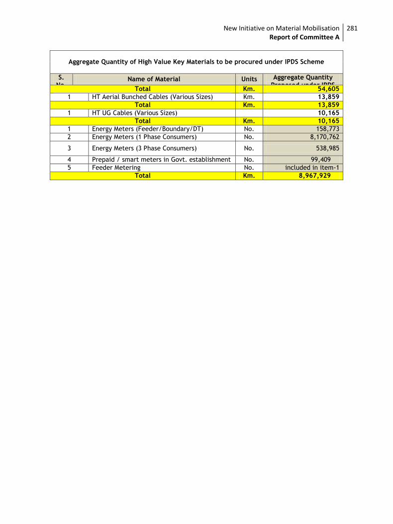
New Initiative on Material Mobilisation Report of Committee A
281
Aggregate Quantity of High Value Key Materials to be procured under IPDS Scheme
S. No.
Name of Material Units Aggregate Quantity Proposed under IPDS
Total Km. 54,605
1 HT Aerial Bunched Cables (Various Sizes) Km. 13,859
Total Km. 13,859
1 HT UG Cables (Various Sizes) 10,165
Total Km. 10,165
1 Energy Meters (Feeder/Boundary/DT) No. 158,773
2 Energy Meters (1 Phase Consumers) No. 8,170,762
3 Energy Meters (3 Phase Consumers) No. 538,985
4 Prepaid / smart meters in Govt. establishment No. 99,409
5 Feeder Metering No. included in item-1
Total Km. 8,967,929
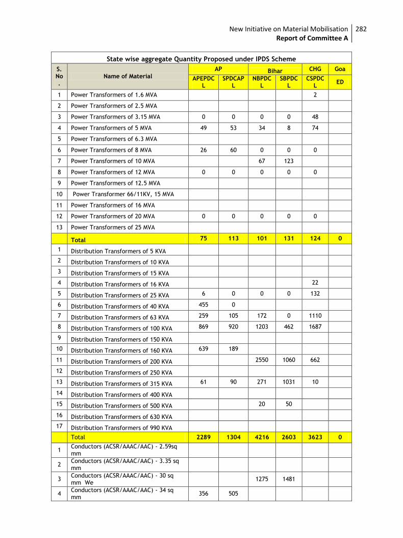
New Initiative on Material Mobilisation Report of Committee A
282
State wise aggregate Quantity Proposed under IPDS Scheme
S. No.
Name of Material
AP Bihar CHG Goa
APEPDCL
SPDCAPL
NBPDCL
SBPDCL
CSPDCL
ED
1 Power Transformers of 1.6 MVA 2
2 Power Transformers of 2.5 MVA
3 Power Transformers of 3.15 MVA 0 0 0 0 48
4 Power Transformers of 5 MVA 49 53 34 8 74
5 Power Transformers of 6.3 MVA
6 Power Transformers of 8 MVA 26 60 0 0 0
7 Power Transformers of 10 MVA 67 123
8 Power Transformers of 12 MVA 0 0 0 0 0
9 Power Transformers of 12.5 MVA
10 Power Transformer 66/11KV, 15 MVA
11 Power Transformers of 16 MVA
12 Power Transformers of 20 MVA 0 0 0 0 0
13 Power Transformers of 25 MVA
Total 75 113 101 131 124 0
1 Distribution Transformers of 5 KVA
2 Distribution Transformers of 10 KVA
3 Distribution Transformers of 15 KVA
4 Distribution Transformers of 16 KVA 22
5 Distribution Transformers of 25 KVA 6 0 0 0 132
6 Distribution Transformers of 40 KVA 455 0
7 Distribution Transformers of 63 KVA 259 105 172 0 1110
8 Distribution Transformers of 100 KVA 869 920 1203 462 1687
9 Distribution Transformers of 150 KVA
10 Distribution Transformers of 160 KVA 639 189
11 Distribution Transformers of 200 KVA 2550 1060 662
12 Distribution Transformers of 250 KVA
13 Distribution Transformers of 315 KVA 61 90 271 1031 10
14 Distribution Transformers of 400 KVA
15 Distribution Transformers of 500 KVA 20 50
16 Distribution Transformers of 630 KVA
17 Distribution Transformers of 990 KVA
Total 2289 1304 4216 2603 3623 0
1 Conductors (ACSR/AAAC/AAC) - 2.59sq mm
2 Conductors (ACSR/AAAC/AAC) - 3.35 sq mm
3 Conductors (ACSR/AAAC/AAC) - 30 sq mm We
1275 1481
4 Conductors (ACSR/AAAC/AAC) - 34 sq mm
356 505
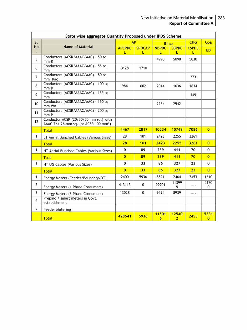
New Initiative on Material Mobilisation Report of Committee A
283
State wise aggregate Quantity Proposed under IPDS Scheme
S. No.
Name of Material
AP Bihar CHG Goa
APEPDCL
SPDCAPL
NBPDCL
SBPDCL
CSPDCL
ED
5 Conductors (ACSR/AAAC/AAC) - 50 sq mm R
4990 5090 5030
6 Conductors (ACSR/AAAC/AAC) - 55 sq mm
3128 1710
7 Conductors (ACSR/AAAC/AAC) - 80 sq mm Rac
273
8 Conductors (ACSR/AAAC/AAC) - 100 sq mm D
984 602 2014 1636 1634
9 Conductors (ACSR/AAAC/AAC) - 135 sq mm
149
10 Conductors (ACSR/AAAC/AAC) - 150 sq mm Wo
2254 2542
11 Conductors (ACSR/AAAC/AAC) - 200 sq mm P
12 Conductor ACSR (20/30/50 mm sq.) with AAAC 7/4.26 mm sq. (or ACSR 100 mm²)
Total 4467 2817 10534 10749 7086 0
1 LT Aerial Bunched Cables (Various Sizes) 28 101 2423 2255 3261
Total 28 101 2423 2255 3261 0
1 HT Aerial Bunched Cables (Various Sizes) 0 89 239 411 70 0
Toal 0 89 239 411 70 0
1 HT UG Cables (Various Sizes) 0 33 86 327 23 0
Total 0 33 86 327 23 0
1 Energy Meters (Feeder/Boundary/DT) 2400 5936 5521 2464 2453 1610
2 Energy Meters (1 Phase Consumers)
413113 0 99901 11399
9 …..
51700
3 Energy Meters (3 Phase Consumers) 13028 0 9594 8939 …..
4 Prepaid / smart meters in Govt. establishment
5 Feeder Metering
Total 428541 5936
115016
125402
2453 5331
0
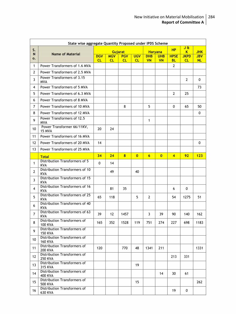
New Initiative on Material Mobilisation Report of Committee A
284
State wise aggregate Quantity Proposed under IPDS Scheme
S. No.
Name of Material Gujarat Haryana
HP J & K JHK
DGVCL
MGVCL
PGVCL
UGVCL
DHBVN
UHBVN
HPSEBL
JKPDCL
JBVNL
1 Power Transformers of 1.6 MVA 2
2 Power Transformers of 2.5 MVA
3 Power Transformers of 3.15 MVA
2 0
4 Power Transformers of 5 MVA 73
5 Power Transformers of 6.3 MVA 2 25
6 Power Transformers of 8 MVA
7 Power Transformers of 10 MVA 8 5 0 65 50
8 Power Transformers of 12 MVA 0
9 Power Transformers of 12.5 MVA
1
10 Power Transformer 66/11KV, 15 MVA
20 24
11 Power Transformers of 16 MVA
12 Power Transformers of 20 MVA 14 0
13 Power Transformers of 25 MVA
Total 34 24 8 0 6 0 4 92 123
1 Distribution Transformers of 5 KVA
0 14
2 Distribution Transformers of 10 KVA
49 40
3 Distribution Transformers of 15 KVA
4 Distribution Transformers of 16 KVA
81 35 6 0
5 Distribution Transformers of 25 KVA
65 118 5 2 54 1275 51
6 Distribution Transformers of 40 KVA
7 Distribution Transformers of 63 KVA
39 12 1457 3 39 90 140 162
8 Distribution Transformers of 100 KVA
165 352 1528 119 751 274 227 698 1183
9 Distribution Transformers of 150 KVA
10 Distribution Transformers of 160 KVA
11 Distribution Transformers of 200 KVA
120 770 48 1341 211 1331
12 Distribution Transformers of 250 KVA
213 331
13 Distribution Transformers of 315 KVA
19
14 Distribution Transformers of 400 KVA
14 30 61
15 Distribution Transformers of 500 KVA
15 262
16 Distribution Transformers of 630 KVA
19 0
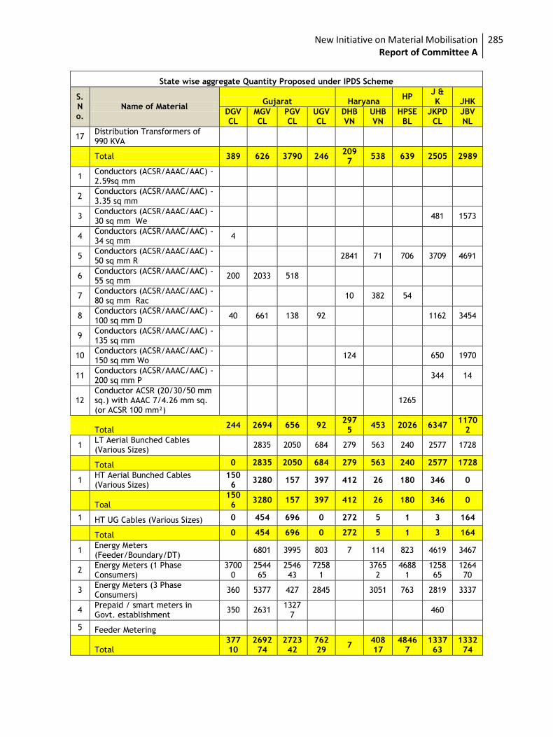
New Initiative on Material Mobilisation Report of Committee A
285
State wise aggregate Quantity Proposed under IPDS Scheme
S. No.
Name of Material Gujarat Haryana
HP J & K JHK
DGVCL
MGVCL
PGVCL
UGVCL
DHBVN
UHBVN
HPSEBL
JKPDCL
JBVNL
17 Distribution Transformers of 990 KVA
Total 389 626 3790 246 2097
538 639 2505 2989
1 Conductors (ACSR/AAAC/AAC) - 2.59sq mm
2 Conductors (ACSR/AAAC/AAC) - 3.35 sq mm
3 Conductors (ACSR/AAAC/AAC) - 30 sq mm We
481 1573
4 Conductors (ACSR/AAAC/AAC) - 34 sq mm
4
5 Conductors (ACSR/AAAC/AAC) - 50 sq mm R
2841 71 706 3709 4691
6 Conductors (ACSR/AAAC/AAC) - 55 sq mm
200 2033 518
7 Conductors (ACSR/AAAC/AAC) - 80 sq mm Rac
10 382 54
8 Conductors (ACSR/AAAC/AAC) - 100 sq mm D
40 661 138 92 1162 3454
9 Conductors (ACSR/AAAC/AAC) - 135 sq mm
10 Conductors (ACSR/AAAC/AAC) - 150 sq mm Wo
124 650 1970
11 Conductors (ACSR/AAAC/AAC) - 200 sq mm P
344 14
12 Conductor ACSR (20/30/50 mm sq.) with AAAC 7/4.26 mm sq. (or ACSR 100 mm²)
1265
Total 244 2694 656 92
2975
453 2026 6347 1170
2
1 LT Aerial Bunched Cables (Various Sizes)
2835 2050 684 279 563 240 2577 1728
Total 0 2835 2050 684 279 563 240 2577 1728
1 HT Aerial Bunched Cables (Various Sizes)
1506
3280 157 397 412 26 180 346 0
Toal
1506
3280 157 397 412 26 180 346 0
1 HT UG Cables (Various Sizes) 0 454 696 0 272 5 1 3 164
Total 0 454 696 0 272 5 1 3 164
1 Energy Meters (Feeder/Boundary/DT)
6801 3995 803 7 114 823 4619 3467
2 Energy Meters (1 Phase Consumers)
37000
254465
254643
72581
3765
2 4688
1 125865
126470
3 Energy Meters (3 Phase Consumers)
360 5377 427 2845 3051 763 2819 3337
4 Prepaid / smart meters in Govt. establishment
350 2631 1327
7 460
5 Feeder Metering
Total 37710
269274
272342
76229
7 40817
48467
133763
133274
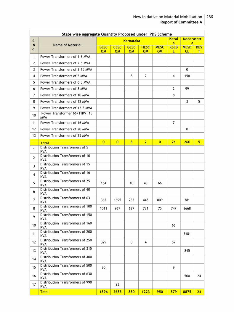
New Initiative on Material Mobilisation Report of Committee A
286
State wise aggregate Quantity Proposed under IPDS Scheme
S. No.
Name of Material
Karnataka Keral
a Maharashtr
a
BESCOM
CESCOM
GESCOM
HESCOM
MESCOM
KSEBL
MESDCL
BEST
1 Power Transformers of 1.6 MVA
2 Power Transformers of 2.5 MVA
3 Power Transformers of 3.15 MVA 0
4 Power Transformers of 5 MVA 8 2 4 158
5 Power Transformers of 6.3 MVA
6 Power Transformers of 8 MVA 2 99
7 Power Transformers of 10 MVA 8
8 Power Transformers of 12 MVA 3 5
9 Power Transformers of 12.5 MVA
10 Power Transformer 66/11KV, 15 MVA
11 Power Transformers of 16 MVA 7
12 Power Transformers of 20 MVA 0
13 Power Transformers of 25 MVA
Total 0 0 8 2 0 21 260 5
1 Distribution Transformers of 5 KVA
2 Distribution Transformers of 10 KVA
3 Distribution Transformers of 15 KVA
4 Distribution Transformers of 16 KVA
5 Distribution Transformers of 25 KVA
164 10 43 66
6 Distribution Transformers of 40 KVA
7 Distribution Transformers of 63 KVA
362 1695 233 445 809 381
8 Distribution Transformers of 100 KVA
1011 967 637 731 75 747 3668
9 Distribution Transformers of 150 KVA
10 Distribution Transformers of 160 KVA
66
11 Distribution Transformers of 200 KVA
3481
12 Distribution Transformers of 250 KVA
329 0 4 57
13 Distribution Transformers of 315 KVA
845
14 Distribution Transformers of 400 KVA
15 Distribution Transformers of 500 KVA
30 9
16 Distribution Transformers of 630 KVA
500 24
17 Distribution Transformers of 990 KVA
23
Total 1896 2685 880 1223 950 879 8875 24
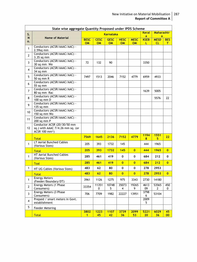
New Initiative on Material Mobilisation Report of Committee A
287
State wise aggregate Quantity Proposed under IPDS Scheme
S. No.
Name of Material
Karnataka Keral
a Maharashtr
a
BESCOM
CESCOM
GESCOM
HESCOM
MESCOM
KSEBL
MESDCL
BEST
1 Conductors (ACSR/AAAC/AAC) - 2.59sq mm
2 Conductors (ACSR/AAAC/AAC) - 3.35 sq mm
3 Conductors (ACSR/AAAC/AAC) - 30 sq mm We
72 132 90 3350
4 Conductors (ACSR/AAAC/AAC) - 34 sq mm
5 Conductors (ACSR/AAAC/AAC) - 50 sq mm R
7497 1513 2046 7152 4779 6959 4933
6 Conductors (ACSR/AAAC/AAC) - 55 sq mm
7 Conductors (ACSR/AAAC/AAC) - 80 sq mm Rac
1639 5005
8 Conductors (ACSR/AAAC/AAC) - 100 sq mm D
5576 22
9 Conductors (ACSR/AAAC/AAC) - 135 sq mm
10 Conductors (ACSR/AAAC/AAC) - 150 sq mm Wo
11 Conductors (ACSR/AAAC/AAC) - 200 sq mm P
12 Conductor ACSR (20/30/50 mm sq.) with AAAC 7/4.26 mm sq. (or ACSR 100 mm²)
Total 7569 1645 2136 7152 4779
11948
15515
22
1 LT Aerial Bunched Cables (Various Sizes)
205 393 1732 145 444 1965
Total 205 393 1732 145 0 444 1965 0
1 HT Aerial Bunched Cables (Various Sizes)
285 461 419 0 0 684 212 0
Toal 285 461 419 0 0 684 212 0
1 HT UG Cables (Various Sizes) 483 62 80 0 0 278 2953
Total 483 62 80 0 0 278 2953 0
1 Energy Meters (Feeder/Boundary/DT)
3961 1126 1275 975 3343 2730 14180
2 Energy Meters (1 Phase Consumers)
33354 11351
0 10748
5 35073
4 19265
9 461309
535652
4500
3 Energy Meters (3 Phase Consumers)
706 7709 1982 22227 13951 3798
6 53104
4 Prepaid / smart meters in Govt. establishment
2009
5
5 Feeder Metering
Total 3802
1 122345
110742
373936
209953
522120
602936
4500
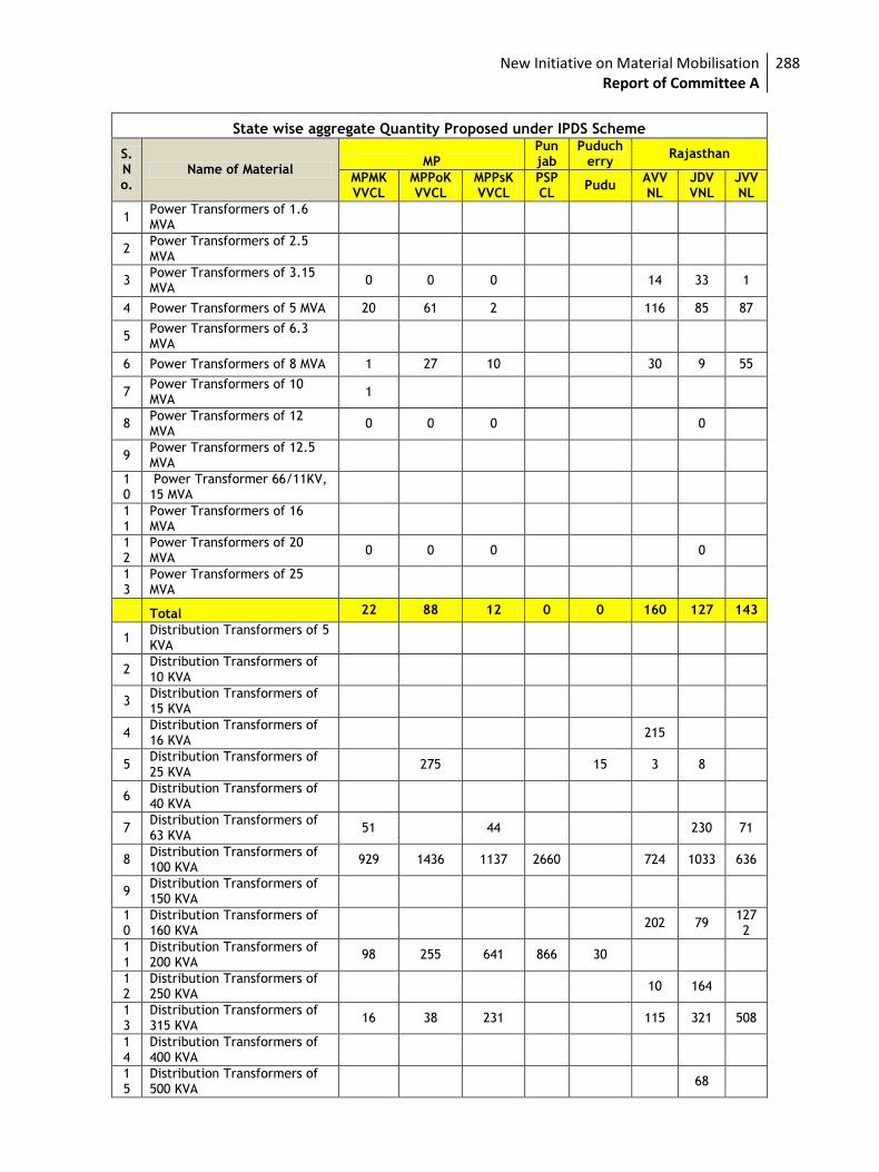
New Initiative on Material Mobilisation Report of Committee A
288
State wise aggregate Quantity Proposed under IPDS Scheme
S. No.
Name of Material MP
Punjab
Puducherry
Rajasthan
MPMKVVCL
MPPoKVVCL
MPPsKVVCL
PSPCL
Pudu AVVNL
JDVVNL
JVVNL
1 Power Transformers of 1.6 MVA
2 Power Transformers of 2.5 MVA
3 Power Transformers of 3.15 MVA
0 0 0 14 33 1
4 Power Transformers of 5 MVA 20 61 2 116 85 87
5 Power Transformers of 6.3 MVA
6 Power Transformers of 8 MVA 1 27 10 30 9 55
7 Power Transformers of 10 MVA
1
8 Power Transformers of 12 MVA
0 0 0 0
9 Power Transformers of 12.5 MVA
10
Power Transformer 66/11KV, 15 MVA
11
Power Transformers of 16 MVA
12
Power Transformers of 20 MVA
0 0 0 0
13
Power Transformers of 25 MVA
Total 22 88 12 0 0 160 127 143
1 Distribution Transformers of 5 KVA
2 Distribution Transformers of 10 KVA
3 Distribution Transformers of 15 KVA
4 Distribution Transformers of 16 KVA
215
5 Distribution Transformers of 25 KVA
275 15 3 8
6 Distribution Transformers of 40 KVA
7 Distribution Transformers of 63 KVA
51 44 230 71
8 Distribution Transformers of 100 KVA
929 1436 1137 2660 724 1033 636
9 Distribution Transformers of 150 KVA
10
Distribution Transformers of 160 KVA
202 79 1272
11
Distribution Transformers of 200 KVA
98 255 641 866 30
12
Distribution Transformers of 250 KVA
10 164
13
Distribution Transformers of 315 KVA
16 38 231 115 321 508
14
Distribution Transformers of 400 KVA
15
Distribution Transformers of 500 KVA
68
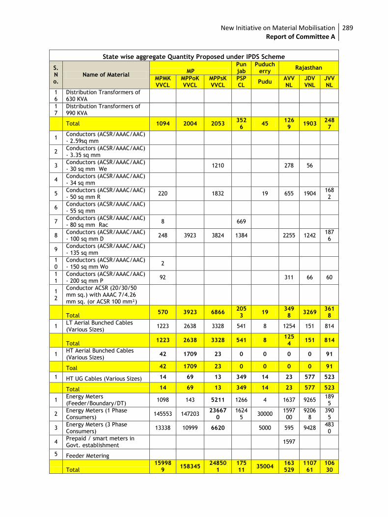
New Initiative on Material Mobilisation Report of Committee A
289
State wise aggregate Quantity Proposed under IPDS Scheme
S. No.
Name of Material MP
Punjab
Puducherry
Rajasthan
MPMKVVCL
MPPoKVVCL
MPPsKVVCL
PSPCL
Pudu AVVNL
JDVVNL
JVVNL
16
Distribution Transformers of 630 KVA
17
Distribution Transformers of 990 KVA
Total 1094 2004 2053 3526
45 1269
1903 2487
1 Conductors (ACSR/AAAC/AAC) - 2.59sq mm
2 Conductors (ACSR/AAAC/AAC) - 3.35 sq mm
3 Conductors (ACSR/AAAC/AAC) - 30 sq mm We
1210 278 56
4 Conductors (ACSR/AAAC/AAC) - 34 sq mm
5 Conductors (ACSR/AAAC/AAC) - 50 sq mm R
220 1832 19 655 1904 1682
6 Conductors (ACSR/AAAC/AAC) - 55 sq mm
7 Conductors (ACSR/AAAC/AAC) - 80 sq mm Rac
8 669
8 Conductors (ACSR/AAAC/AAC) - 100 sq mm D
248 3923 3824 1384 2255 1242 1876
9 Conductors (ACSR/AAAC/AAC) - 135 sq mm
10
Conductors (ACSR/AAAC/AAC) - 150 sq mm Wo
2
11
Conductors (ACSR/AAAC/AAC) - 200 sq mm P
92 311 66 60
12
Conductor ACSR (20/30/50 mm sq.) with AAAC 7/4.26 mm sq. (or ACSR 100 mm²)
Total 570 3923 6866
2053
19 3498
3269 3618
1 LT Aerial Bunched Cables (Various Sizes)
1223 2638 3328 541 8 1254 151 814
Total
1223 2638 3328 541 8 1254
151 814
1 HT Aerial Bunched Cables (Various Sizes)
42 1709 23 0 0 0 0 91
Toal 42 1709 23 0 0 0 0 91
1 HT UG Cables (Various Sizes) 14 69 13 349 14 23 577 523
Total 14 69 13 349 14 23 577 523
1 Energy Meters (Feeder/Boundary/DT)
1098 143 5211 1266 4 1637 9265 1895
2 Energy Meters (1 Phase Consumers)
145553 147203 23667
0 1624
5 30000
159700
92068
3905
3 Energy Meters (3 Phase Consumers)
13338 10999 6620 5000 595 9428 4830
4 Prepaid / smart meters in Govt. establishment
1597
5 Feeder Metering
Total 15998
9 158345
248501
17511
35004 163529
110761
10630
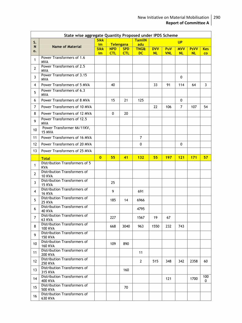
New Initiative on Material Mobilisation Report of Committee A
290
State wise aggregate Quantity Proposed under IPDS Scheme
S. No.
Name of Material
Sikkim Telengana
TamilNadu
UP
Sikkim
NPDCTL
SPDCTL
TNG&DC
DVVNL
PuVVNL
MVVNL
PsVVNL
Kesco
1 Power Transformers of 1.6 MVA
2 Power Transformers of 2.5 MVA
3 Power Transformers of 3.15 MVA
0
4 Power Transformers of 5 MVA 40 33 91 114 64 3
5 Power Transformers of 6.3 MVA
6 Power Transformers of 8 MVA 15 21 125 0
7 Power Transformers of 10 MVA 22 106 7 107 54
8 Power Transformers of 12 MVA 0 20
9 Power Transformers of 12.5 MVA
10 Power Transformer 66/11KV, 15 MVA
11 Power Transformers of 16 MVA 7
12 Power Transformers of 20 MVA 0 0
13 Power Transformers of 25 MVA
Total 0 55 41 132 55 197 121 171 57
1 Distribution Transformers of 5 KVA
2 Distribution Transformers of 10 KVA
3 Distribution Transformers of 15 KVA
25
4 Distribution Transformers of 16 KVA
9 691
5 Distribution Transformers of 25 KVA
185 14 6966
6 Distribution Transformers of 40 KVA
4795
7 Distribution Transformers of 63 KVA
227 1567 19 67
8 Distribution Transformers of 100 KVA
668 3040 963 1550 232 743
9 Distribution Transformers of 150 KVA
10 Distribution Transformers of 160 KVA
109 890
11 Distribution Transformers of 200 KVA
11
12 Distribution Transformers of 250 KVA
2 515 348 342 2358 60
13 Distribution Transformers of 315 KVA
160
14 Distribution Transformers of 400 KVA
121 1700 1000
15 Distribution Transformers of 500 KVA
70
16 Distribution Transformers of 630 KVA
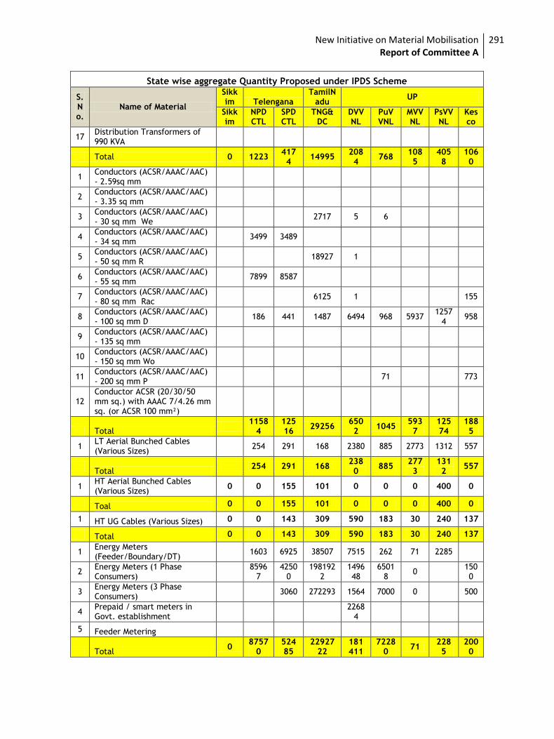
New Initiative on Material Mobilisation Report of Committee A
291
State wise aggregate Quantity Proposed under IPDS Scheme
S. No.
Name of Material
Sikkim Telengana
TamilNadu
UP
Sikkim
NPDCTL
SPDCTL
TNG&DC
DVVNL
PuVVNL
MVVNL
PsVVNL
Kesco
17 Distribution Transformers of 990 KVA
Total 0 1223 4174
14995 2084
768 1085
4058
1060
1 Conductors (ACSR/AAAC/AAC) - 2.59sq mm
2 Conductors (ACSR/AAAC/AAC) - 3.35 sq mm
3 Conductors (ACSR/AAAC/AAC) - 30 sq mm We
2717 5 6
4 Conductors (ACSR/AAAC/AAC) - 34 sq mm
3499 3489
5 Conductors (ACSR/AAAC/AAC) - 50 sq mm R
18927 1
6 Conductors (ACSR/AAAC/AAC) - 55 sq mm
7899 8587
7 Conductors (ACSR/AAAC/AAC) - 80 sq mm Rac
6125 1 155
8 Conductors (ACSR/AAAC/AAC) - 100 sq mm D
186 441 1487 6494 968 5937 1257
4 958
9 Conductors (ACSR/AAAC/AAC) - 135 sq mm
10 Conductors (ACSR/AAAC/AAC) - 150 sq mm Wo
11 Conductors (ACSR/AAAC/AAC) - 200 sq mm P
71 773
12 Conductor ACSR (20/30/50 mm sq.) with AAAC 7/4.26 mm sq. (or ACSR 100 mm²)
Total
11584
12516
29256 6502
1045 5937
12574
1885
1 LT Aerial Bunched Cables (Various Sizes)
254 291 168 2380 885 2773 1312 557
Total
254 291 168 2380
885 2773
1312
557
1 HT Aerial Bunched Cables (Various Sizes)
0 0 155 101 0 0 0 400 0
Toal 0 0 155 101 0 0 0 400 0
1 HT UG Cables (Various Sizes) 0 0 143 309 590 183 30 240 137
Total 0 0 143 309 590 183 30 240 137
1 Energy Meters (Feeder/Boundary/DT)
1603 6925 38507 7515 262 71 2285
2 Energy Meters (1 Phase Consumers)
8596
7 4250
0 198192
2 149648
65018
0 1500
3 Energy Meters (3 Phase Consumers)
3060 272293 1564 7000 0 500
4 Prepaid / smart meters in Govt. establishment
2268
4
5 Feeder Metering
Total 0
87570
52485
2292722
181411
72280
71 2285
2000
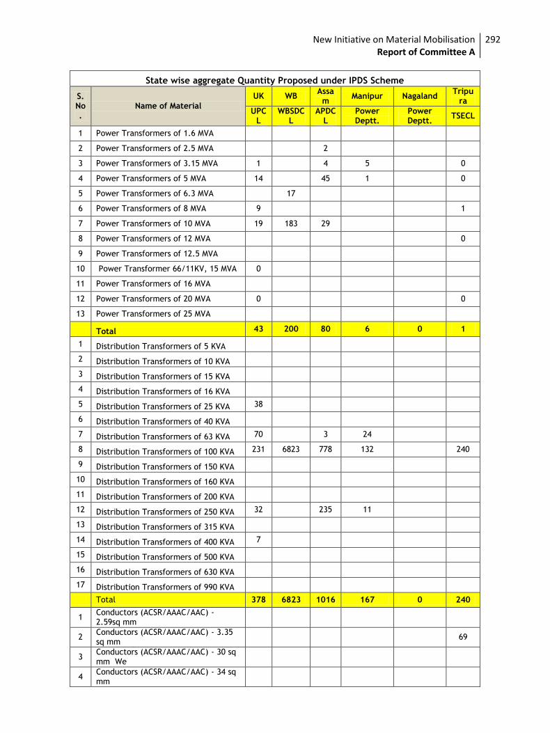
New Initiative on Material Mobilisation Report of Committee A
292
State wise aggregate Quantity Proposed under IPDS Scheme
S. No.
Name of Material
UK WB Assam
Manipur Nagaland Tripu
ra
UPCL
WBSDCL
APDCL
Power Deptt.
Power Deptt.
TSECL
1 Power Transformers of 1.6 MVA
2 Power Transformers of 2.5 MVA 2
3 Power Transformers of 3.15 MVA 1 4 5 0
4 Power Transformers of 5 MVA 14 45 1 0
5 Power Transformers of 6.3 MVA 17
6 Power Transformers of 8 MVA 9 1
7 Power Transformers of 10 MVA 19 183 29
8 Power Transformers of 12 MVA 0
9 Power Transformers of 12.5 MVA
10 Power Transformer 66/11KV, 15 MVA 0
11 Power Transformers of 16 MVA
12 Power Transformers of 20 MVA 0 0
13 Power Transformers of 25 MVA
Total 43 200 80 6 0 1
1 Distribution Transformers of 5 KVA
2 Distribution Transformers of 10 KVA
3 Distribution Transformers of 15 KVA
4 Distribution Transformers of 16 KVA
5 Distribution Transformers of 25 KVA 38
6 Distribution Transformers of 40 KVA
7 Distribution Transformers of 63 KVA 70 3 24
8 Distribution Transformers of 100 KVA 231 6823 778 132 240
9 Distribution Transformers of 150 KVA
10 Distribution Transformers of 160 KVA
11 Distribution Transformers of 200 KVA
12 Distribution Transformers of 250 KVA 32 235 11
13 Distribution Transformers of 315 KVA
14 Distribution Transformers of 400 KVA 7
15 Distribution Transformers of 500 KVA
16 Distribution Transformers of 630 KVA
17 Distribution Transformers of 990 KVA
Total 378 6823 1016 167 0 240
1 Conductors (ACSR/AAAC/AAC) - 2.59sq mm
2 Conductors (ACSR/AAAC/AAC) - 3.35 sq mm
69
3 Conductors (ACSR/AAAC/AAC) - 30 sq mm We
4 Conductors (ACSR/AAAC/AAC) - 34 sq mm
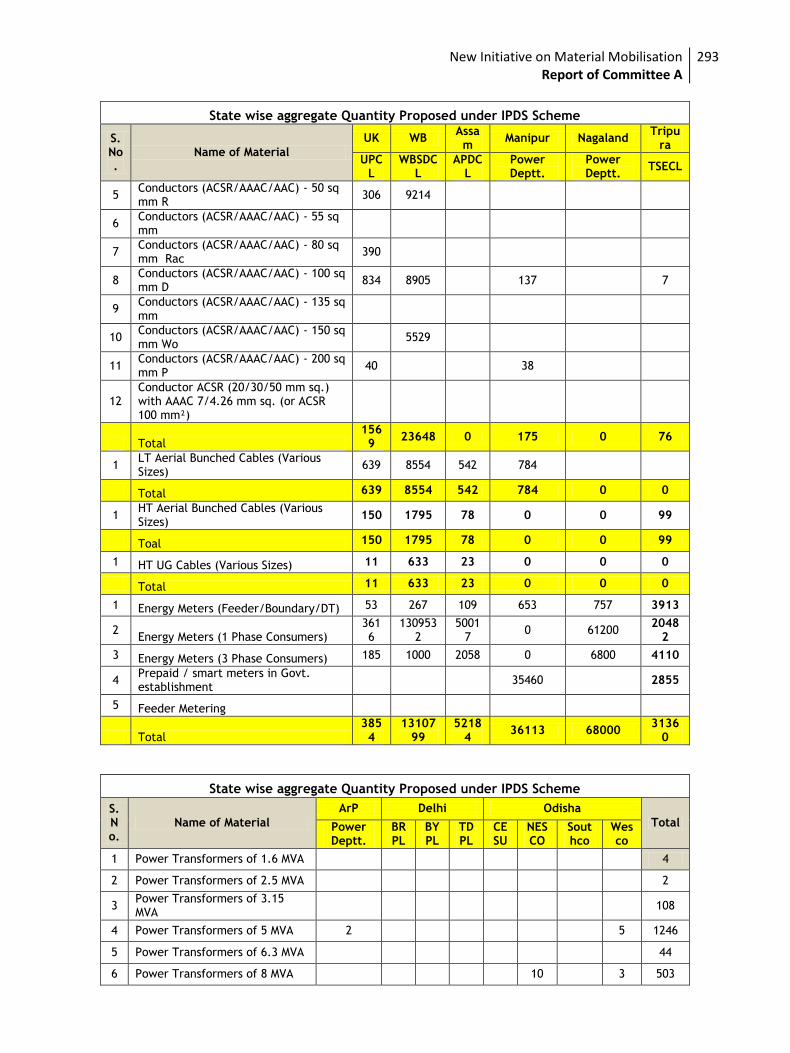
New Initiative on Material Mobilisation Report of Committee A
293
State wise aggregate Quantity Proposed under IPDS Scheme
S. No.
Name of Material
UK WB Assam
Manipur Nagaland Tripu
ra
UPCL
WBSDCL
APDCL
Power Deptt.
Power Deptt.
TSECL
5 Conductors (ACSR/AAAC/AAC) - 50 sq mm R
306 9214
6 Conductors (ACSR/AAAC/AAC) - 55 sq mm
7 Conductors (ACSR/AAAC/AAC) - 80 sq mm Rac
390
8 Conductors (ACSR/AAAC/AAC) - 100 sq mm D
834 8905 137
7
9 Conductors (ACSR/AAAC/AAC) - 135 sq mm
10 Conductors (ACSR/AAAC/AAC) - 150 sq mm Wo
5529
11 Conductors (ACSR/AAAC/AAC) - 200 sq mm P
40 38
12 Conductor ACSR (20/30/50 mm sq.) with AAAC 7/4.26 mm sq. (or ACSR 100 mm²)
Total 1569
23648 0 175 0 76
1 LT Aerial Bunched Cables (Various Sizes)
639 8554 542 784
Total 639 8554 542 784 0 0
1 HT Aerial Bunched Cables (Various Sizes)
150 1795 78 0 0 99
Toal 150 1795 78 0 0 99
1 HT UG Cables (Various Sizes) 11 633 23 0 0 0
Total 11 633 23 0 0 0
1 Energy Meters (Feeder/Boundary/DT) 53 267 109 653 757 3913
2 Energy Meters (1 Phase Consumers)
3616
1309532
50017
0 61200 2048
2
3 Energy Meters (3 Phase Consumers) 185 1000 2058 0 6800 4110
4 Prepaid / smart meters in Govt. establishment
35460 2855
5 Feeder Metering
Total 3854
1310799
52184
36113 68000 3136
0
State wise aggregate Quantity Proposed under IPDS Scheme
S. No.
Name of Material
ArP Delhi Odisha
Total Power Deptt.
BRPL
BYPL
TDPL
CESU
NESCO
Southco
Wesco
1 Power Transformers of 1.6 MVA 4
2 Power Transformers of 2.5 MVA 2
3 Power Transformers of 3.15 MVA
108
4 Power Transformers of 5 MVA 2 5 1246
5 Power Transformers of 6.3 MVA 44
6 Power Transformers of 8 MVA 10 3 503
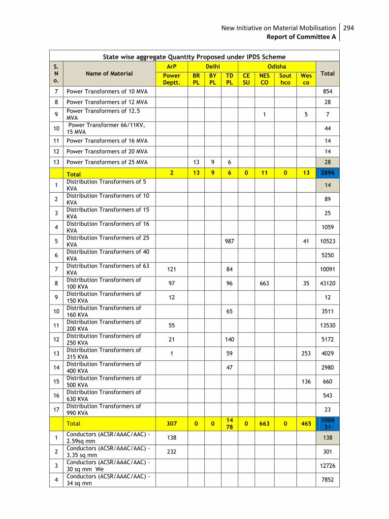
New Initiative on Material Mobilisation Report of Committee A
294
State wise aggregate Quantity Proposed under IPDS Scheme
S. No.
Name of Material
ArP Delhi Odisha
Total Power Deptt.
BRPL
BYPL
TDPL
CESU
NESCO
Southco
Wesco
7 Power Transformers of 10 MVA 854
8 Power Transformers of 12 MVA 28
9 Power Transformers of 12.5 MVA
1 5 7
10 Power Transformer 66/11KV, 15 MVA
44
11 Power Transformers of 16 MVA 14
12 Power Transformers of 20 MVA 14
13 Power Transformers of 25 MVA 13 9 6 28
Total 2 13 9 6 0 11 0 13 2896
1 Distribution Transformers of 5 KVA
14
2 Distribution Transformers of 10 KVA
89
3 Distribution Transformers of 15 KVA
25
4 Distribution Transformers of 16 KVA
1059
5 Distribution Transformers of 25 KVA
987 41 10523
6 Distribution Transformers of 40 KVA
5250
7 Distribution Transformers of 63 KVA
121 84 10091
8 Distribution Transformers of 100 KVA
97 96 663 35 43120
9 Distribution Transformers of 150 KVA
12 12
10 Distribution Transformers of 160 KVA
65 3511
11 Distribution Transformers of 200 KVA
55 13530
12 Distribution Transformers of 250 KVA
21 140 5172
13 Distribution Transformers of 315 KVA
1 59 253 4029
14 Distribution Transformers of 400 KVA
47 2980
15 Distribution Transformers of 500 KVA
136 660
16 Distribution Transformers of 630 KVA
543
17 Distribution Transformers of 990 KVA
23
Total 307 0 0 1478
0 663 0 465 100631
1 Conductors (ACSR/AAAC/AAC) - 2.59sq mm
138 138
2 Conductors (ACSR/AAAC/AAC) - 3.35 sq mm
232 301
3 Conductors (ACSR/AAAC/AAC) - 30 sq mm We
12726
4 Conductors (ACSR/AAAC/AAC) - 34 sq mm
7852
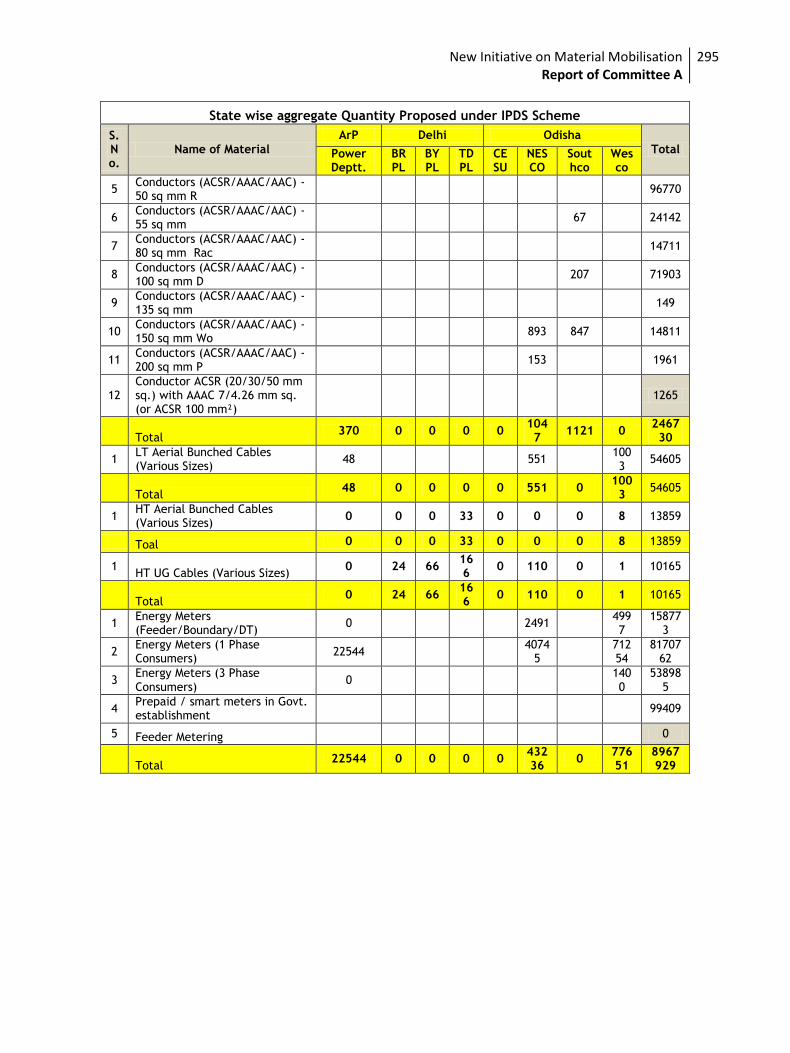
New Initiative on Material Mobilisation Report of Committee A
295
State wise aggregate Quantity Proposed under IPDS Scheme
S. No.
Name of Material
ArP Delhi Odisha
Total Power Deptt.
BRPL
BYPL
TDPL
CESU
NESCO
Southco
Wesco
5 Conductors (ACSR/AAAC/AAC) - 50 sq mm R
96770
6 Conductors (ACSR/AAAC/AAC) - 55 sq mm
67 24142
7 Conductors (ACSR/AAAC/AAC) - 80 sq mm Rac
14711
8 Conductors (ACSR/AAAC/AAC) - 100 sq mm D
207 71903
9 Conductors (ACSR/AAAC/AAC) - 135 sq mm
149
10 Conductors (ACSR/AAAC/AAC) - 150 sq mm Wo
893 847 14811
11 Conductors (ACSR/AAAC/AAC) - 200 sq mm P
153 1961
12 Conductor ACSR (20/30/50 mm sq.) with AAAC 7/4.26 mm sq. (or ACSR 100 mm²)
1265
Total 370 0 0 0 0
1047
1121 0 246730
1 LT Aerial Bunched Cables (Various Sizes)
48 551 1003
54605
Total
48 0 0 0 0 551 0 1003
54605
1 HT Aerial Bunched Cables (Various Sizes)
0 0 0 33 0 0 0 8 13859
Toal 0 0 0 33 0 0 0 8 13859
1 HT UG Cables (Various Sizes)
0 24 66 166
0 110 0 1 10165
Total
0 24 66 166
0 110 0 1 10165
1 Energy Meters (Feeder/Boundary/DT)
0 2491 4997
158773
2 Energy Meters (1 Phase Consumers)
22544 4074
5
71254
8170762
3 Energy Meters (3 Phase Consumers)
0
1400
538985
4 Prepaid / smart meters in Govt. establishment
99409
5 Feeder Metering 0
Total 22544 0 0 0 0
43236
0 77651
8967929
New Initiative on Material Mobilisation Report of Committee A
296
Annexure-VIII
Household Consumption
Details
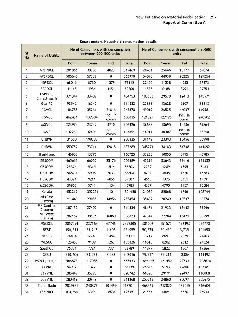
New Initiative on Material Mobilisation Report of Committee A
297
Smart meters-Household consumption details
Sl No
Name of Utility
No of Consumers with consumption between 200-500 units
No of Consumers with consumption >500 units
Dom Comm Ind Total Dom Comm Ind Total
1 APEPDCL 281866 30780 4823 317469 28431 25666 15777 69874
2 APSPDCL 506640 57339 0 563979 54090 44939 28225 127254
3 NBPDCL 68016 8720 1379 78115 22400 11538 4035 37973
4 SBPDCL 41165 4984 4151 50300 14575 6188 8991 29754
5 CSPDCL,
Chhattisgarh 371344 33409 0 404753 103588 29570 12413 145571
6 Goa PD 98542 16340 0 114882 23683 12628 2507 38818
7 PGVCL 186788 35266 21816 243870 49019 26525 44037 119581
8 DGVCL 462431 137584 incl in comm
600015 121327 127175 incl in comm
248502
9 MGVCL 223974 23742 8710 256426 36683 18695 14486 69864
10 UGVCL 132250 32601 incl in comm
164851 16911 40307 incl in comm
57218
11 UHBVN 31500 199335 0 230835 39149 23393 18456 80998
12 DHBVN 550757 73714 12818 637289 348771 38183 54738 441692
13 Jharkhand 146955 13770
160725 33235 10055 3495 46785
14 BESCOM 465663 66050 25176 556889 45296 53643 32416 131355
15 CESCOM 25374 5315 1514 32203 2299 4289 1895 8483
16 GESCOM 58870 5905 2033 66808 8712 4845 1826 15383
17 HESCOM 43321 9211 6855 59387 4665 7375 5351 17391
18 MESCOM 39908 5741 1134 46783 4337 4790 1457 10584
19 Kerala 452217 1352231 10 1804458 21080 85868 1796 108744
20 MP(East Discom)
211440 29058 14956 255454 35492 20249 10537 66278
21 MP(Central
Discom) 287132 27402 0 314534 48171 21933 13442 83546
22 MP(West Discom)
282167 38596 16060 336823 42544 27784 16471 86799
23 MSEDCL 2057391 227168 67746 2352305 301002 151575 122193 574770
24 BEST 196,515 55,942 1,602 254059 50,535 50,420 3,735 104690
25 NESCO 78414 12249 1454 92117 13717 8651 2035 24403
26 WESCO 125450 9109 1267 135826 16510 8202 2812 27524
27 SouthCo 75331 7721 737 83789 11877 5822 1667 19366
28 CESU 210,606 23,028 8,382 242016 79,217 22,211 10,064 111492
29 PSPCL, Punjab 566875 117058 0 683933 1694445 121450 92733 1908628
30 AVVNL 54917 7322 0 62239 25628 9153 72800 107581
31 JaVVNL 285449 35293 0 320742 66320 29191 22497 118008
32 JoVVNL 280419 30949 0 311368 255718 24860 25097 305675
33 Tamil Nadu 2839635 240877 101499 3182011 468369 212820 135415 816604
34 TSNPDCL 104,690 17091 3570 125351 8,373 14691 5870 28934
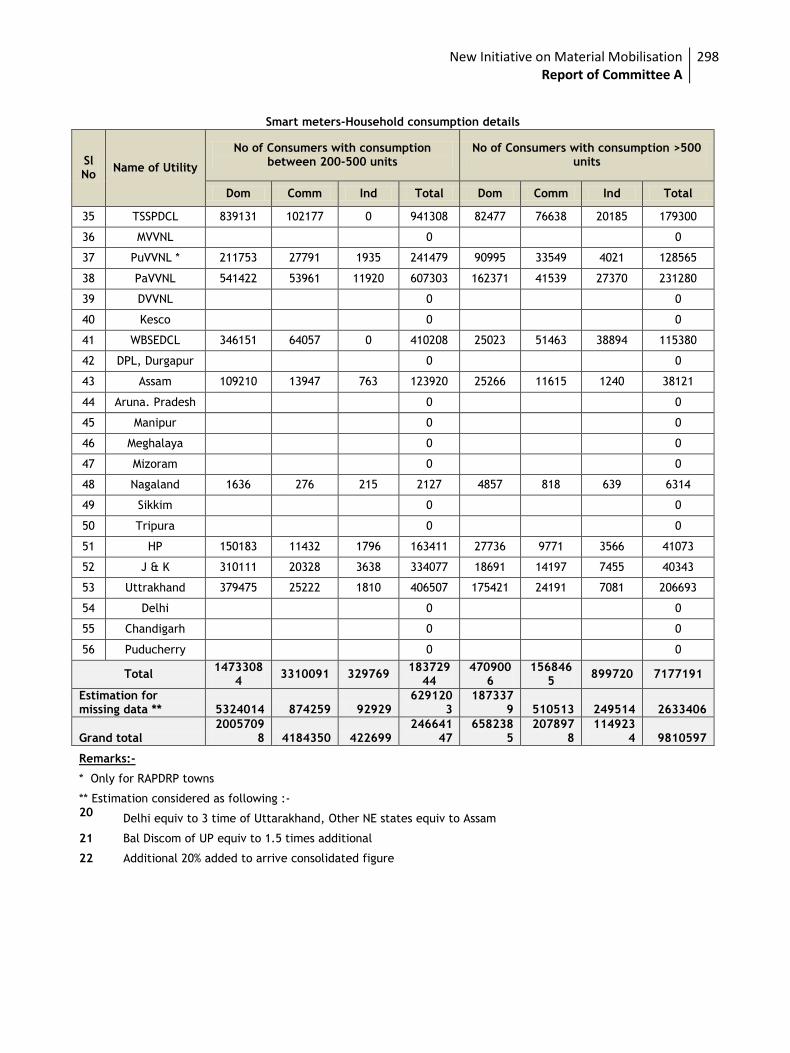
New Initiative on Material Mobilisation Report of Committee A
298
Smart meters-Household consumption details
Sl No
Name of Utility
No of Consumers with consumption between 200-500 units
No of Consumers with consumption >500 units
Dom Comm Ind Total Dom Comm Ind Total
35 TSSPDCL 839131 102177 0 941308 82477 76638 20185 179300
36 MVVNL
0
0
37 PuVVNL * 211753 27791 1935 241479 90995 33549 4021 128565
38 PaVVNL 541422 53961 11920 607303 162371 41539 27370 231280
39 DVVNL
0
0
40 Kesco
0
0
41 WBSEDCL 346151 64057 0 410208 25023 51463 38894 115380
42 DPL, Durgapur
0
0
43 Assam 109210 13947 763 123920 25266 11615 1240 38121
44 Aruna. Pradesh
0
0
45 Manipur
0
0
46 Meghalaya
0
0
47 Mizoram
0
0
48 Nagaland 1636 276 215 2127 4857 818 639 6314
49 Sikkim
0
0
50 Tripura
0
0
51 HP 150183 11432 1796 163411 27736 9771 3566 41073
52 J & K 310111 20328 3638 334077 18691 14197 7455 40343
53 Uttrakhand 379475 25222 1810 406507 175421 24191 7081 206693
54 Delhi
0
0
55 Chandigarh
0
0
56 Puducherry
0
0
Total 1473308
4 3310091 329769
18372944
4709006
1568465
899720 7177191
Estimation for missing data ** 5324014 874259 92929
6291203
1873379 510513 249514 2633406
Grand total 2005709
8 4184350 422699 246641
47 658238
5 207897
8 114923
4 9810597
Remarks:-
* Only for RAPDRP towns
** Estimation considered as following :- 20
Delhi equiv to 3 time of Uttarakhand, Other NE states equiv to Assam
21 Bal Discom of UP equiv to 1.5 times additional
22 Additional 20% added to arrive consolidated figure