Embed Size (px)
Citation preview
MINNESOTA ON THE MAP INVENTORY, EXHIBIT LAYOUT, ASSEMBLY, DISASSEMBLY, PACKING INSTRUCTIONS
Exhibits To Go! The Minnesota Historical Society’s Traveling Exhibits Program – MN ON THE MAP 10-4-2011 Page 1 of 35
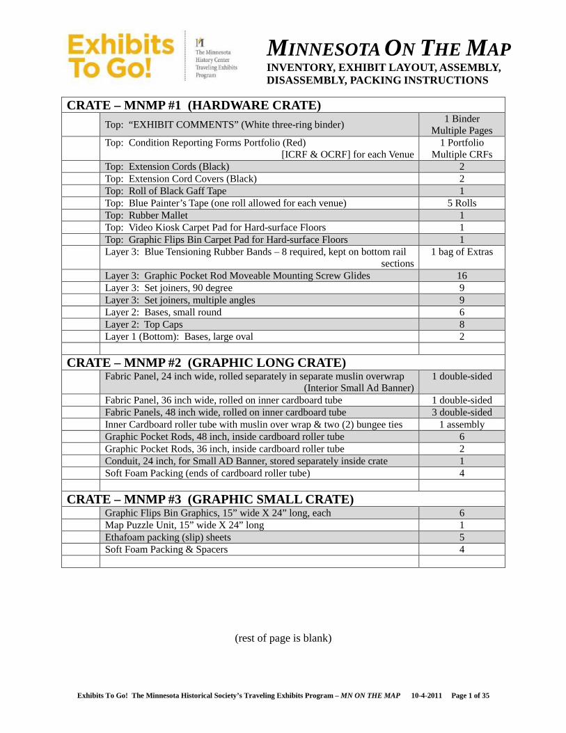
CRATE – MNMP #1 (HARDWARE CRATE) Top: “EXHIBIT COMMENTS” (White three-ring binder)
1 Binder Multiple Pages
Top: Condition Reporting Forms Portfolio (Red) [ICRF & OCRF] for each Venue
1 Portfolio Multiple CRFs
Top: Extension Cords (Black) 2 Top: Extension Cord Covers (Black) 2 Top: Roll of Black Gaff Tape 1 Top: Blue Painter’s Tape (one roll allowed for each venue) 5 Rolls Top: Rubber Mallet 1 Top: Video Kiosk Carpet Pad for Hard-surface Floors 1 Top: Graphic Flips Bin Carpet Pad for Hard-surface Floors 1 Layer 3: Blue Tensioning Rubber Bands – 8 required, kept on bottom rail
sections 1 bag of Extras
Layer 3: Graphic Pocket Rod Moveable Mounting Screw Glides 16 Layer 3: Set joiners, 90 degree 9 Layer 3: Set joiners, multiple angles 9 Layer 2: Bases, small round 6 Layer 2: Top Caps 8 Layer 1 (Bottom): Bases, large oval 2
CRATE – MNMP #2 (GRAPHIC LONG CRATE) Fabric Panel, 24 inch wide, rolled separately in separate muslin overwrap
(Interior Small Ad Banner) 1 double-sided
Fabric Panel, 36 inch wide, rolled on inner cardboard tube 1 double-sided Fabric Panels, 48 inch wide, rolled on inner cardboard tube 3 double-sided Inner Cardboard roller tube with muslin over wrap & two (2) bungee ties 1 assembly Graphic Pocket Rods, 48 inch, inside cardboard roller tube 6 Graphic Pocket Rods, 36 inch, inside cardboard roller tube 2 Conduit, 24 inch, for Small AD Banner, stored separately inside crate 1 Soft Foam Packing (ends of cardboard roller tube) 4
CRATE – MNMP #3 (GRAPHIC SMALL CRATE) Graphic Flips Bin Graphics, 15” wide X 24” long, each 6 Map Puzzle Unit, 15” wide X 24” long 1 Ethafoam packing (slip) sheets 5 Soft Foam Packing & Spacers 4
(rest of page is blank)

MINNESOTA ON THE MAP INVENTORY, EXHIBIT LAYOUT, ASSEMBLY, DISASSEMBLY, PACKING INSTRUCTIONS
Exhibits To Go! The Minnesota Historical Society’s Traveling Exhibits Program – MN ON THE MAP 10-4-2011 Page 2 of 35
CRATE – MNMP #4 (GRAPHIC MID-LENGTH CRATE) Fabric Panel, 36 inch wide X 162” long rolled on inner cardboard tube
(Interior Large AD Banner) 1 double-sided
Inner Cardboard roller tube with separate muslin over wrap & two (2) bungee ties
1 assembly
Conduit, 36 inch, for Large AD Banner, stored separately inside crate 1 Soft Foam Packing (ends of cardboard roller tube) & around conduit 4
CRATE – MNMP #5 (INTERACTIVE ATLAS ELEMENTS) Encapsulated Atlas Elements 3 Ethafoam packing (slip) sheets 4 Soft Foam Packing & Spacers 4
LONG & SHORT RAIL SECTIONS PACK (EIGHT [8] RAILS TO TAL) Rail, 48 inch top (no blue rubber bands) 3 Rail, 48 inch bottom (two blue rubber bands, each) 3 Rail, 36 inch top (no blue rubber bands) 1 Rail, 36 inch bottom (two blue rubber bands, each) 1
POST SECTIONS PACK (SIXTEEN [16] POST SECTIONS TOTAL) Posts in Section Pack #1 8 Posts in Section Pack #2 8
ACCESSORIES/TOOL BAG Cleaning kit (Plexi cleaner and wipes – box of wipes strapped to outside) 1 Tour Manual (three-ring binder) 1 Manual 16 Foot Tape Measure 1 Extra Zip-ties for Kiosk Power Cord(s) – small, black 1 bag of 100 Extra Zip-ties for Kiosk Power Cord(s) – medium, black 1 bag of 100 Side-cutter to remove Zip-ties 1 Extra Graphic Pocket Rod Moveable Mounting Screw Glides 1 bag of 6 Extra Set joiners, 90 degree 1 bag of 6 Extra Set joiners, multiple angles 1 bag of 8 Spacer Tool – for setting upper Moveable Mounting Screw Glides 1 Slip-joint Pliers to tighten upper Moveable Mounting Screw Glides 1 Plastic Accessory Box with Video Monitor/Kiosk Equipment, including:
1
• One (1) Flashlight • One (1) Key – to open Monitor • Many Small Black Zip-ties
• One (1) Multi-tipped Screwdriver • Two (2) Allen Wrenches
• Twelve (12) Allen-head Socket Screws
(rest of page is blank)

MINNESOTA ON THE MAP INVENTORY, EXHIBIT LAYOUT, ASSEMBLY, DISASSEMBLY, PACKING INSTRUCTIONS
Exhibits To Go! The Minnesota Historical Society’s Traveling Exhibits Program – MN ON THE MAP 10-4-2011 Page 3 of 35
CASEWORK – GRAPHIC FLIPS BIN Casework 1 Padded Blanket Cover 2 Straps for Padded Blanket Cover 4
CASEWORK – VIDEO MONITOR/KIOSK Kiosk Unit with built-in Monitor 1 Padded Blanket Cover 2 Straps for Padded Blanket Cover 4 Padded & Velcro Screen Transport Cover 1 Padded & Velcro Volume Control Knob Transport Cover 1
MISCELLANEOUS Four-wheel Furniture Dollies* 2 (*) Furniture Dollies
• One (1) with oversized black carpet base for moving Video Monitor/Kiosk & Graphic Flips Bin
• One (1) with black rubber-topped grip for the Hardware & Graphic Crates
HOST SITE EXHIBIT REQUIREMENTS Folding Tables, 96”l X 30”w, each 2 Power Supply, 110 Volt, Grounded (three-prong household) Outlet 1 Picture Hanger Wire – or equivalent, to hang 24” Graphic AD Banner &
Conduit at each Venue Length to be
determine by each Venue’s location
Folding Tables, 36”l X 36”w 1 Three-step Step Ladder 1
NOTE: EACH HOST SITE IS RESPONSIBLE FOR LIGHTING T HE EXHIBIT. MINNESOTA ON THE MAP TRAVELS WITHOUT LIGHTING EQUIPMENT.
(rest of page is blank)
MINNESOTA ON THE MAP INVENTORY, EXHIBIT LAYOUT, ASSEMBLY, DISASSEMBLY, PACKING INSTRUCTIONS
Exhibits To Go! The Minnesota Historical Society’s Traveling Exhibits Program – MN ON THE MAP 10-4-2011 Page 4 of 35
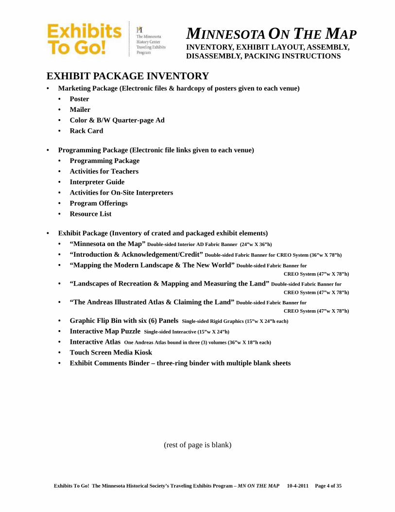
EXHIBIT PACKAGE INVENTORY • Marketing Package (Electronic files & hardcopy of posters given to each venue)
• Poster
• Mailer
• Color & B/W Quarter-page Ad
• Rack Card
• Programming Package (Electronic file links given to each venue)
• Programming Package
• Activities for Teachers
• Interpreter Guide
• Activities for On-Site Interpreters
• Program Offerings
• Resource List
• Exhibit Package (Inventory of crated and packaged exhibit elements)
• “Minnesota on the Map” Double-sided Interior AD Fabric Banner (24”w X 36”h)
• “Introduction & Acknowledgement/Credit” Double-sided Fabric Banner for CREO System (36”w X 78”h)
• “Mapping the Modern Landscape & The New World” Double-sided Fabric Banner for
CREO System (47”w X 78”h)
• “Landscapes of Recreation & Mapping and Measuring the Land” Double-sided Fabric Banner for
CREO System (47”w X 78”h)
• “The Andreas Illustrated Atlas & Claiming the Land” Double-sided Fabric Banner for
CREO System (47”w X 78”h)
• Graphic Flip Bin with six (6) Panels Single-sided Rigid Graphics (15”w X 24”h each)
• Interactive Map Puzzle Single-sided Interactive (15”w X 24”h)
• Interactive Atlas One Andreas Atlas bound in three (3) volumes (36”w X 18”h each)
• Touch Screen Media Kiosk
• Exhibit Comments Binder – three-ring binder with multiple blank sheets
(rest of page is blank)
MINNESOTA ON THE MAP INVENTORY, EXHIBIT LAYOUT, ASSEMBLY, DISASSEMBLY, PACKING INSTRUCTIONS
Exhibits To Go! The Minnesota Historical Society’s Traveling Exhibits Program – MN ON THE MAP 10-4-2011 Page 5 of 35
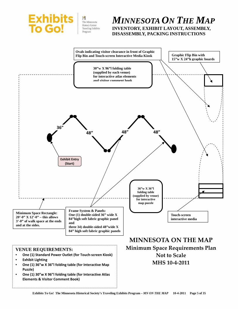
36” 48” 48” 48”
Exhibit Entry
(Start)
MINNESOTA ON THE MAP Minimum Space Requirements Plan
Not to Scale
MHS 10-4-2011
VENUE REQUIREMENTS: • One (1) Standard Power Outlet (for Touch-screen Kiosk)
• Exhibit Lighting
• One (1) 36”w X 36”l folding table (for Interactive Map
Puzzle)
• One (1) 30”w X 96”l folding table (for Interactive Atlas
Elements & Visitor Comment Book)
Minimum Space Rectangle: 20’-0” X 12’-0” – this allows 3’-0” of walk space at the ends and at the sides.
Touch-screen interactive media
Graphic Flip Bin with 15”w X 24”h graphic boards
Frame System & Panels: One (1) double-sided 36” wide X 84”high soft fabric graphic panel and three 34) double-sided 48”wide X 84” high soft fabric graphic panels
Ovals indicating visitor clearance in front of Graphic Flip Bin and Touch-screen Interactive Media Kiosk
30”w X 96”l folding table (supplied by each venue) for interactive atlas elements and visitor comment book
36”w X 36”l folding table
(supplied by venue) for interactive
map puzzle
MINNESOTA ON THE MAP INVENTORY, EXHIBIT LAYOUT, ASSEMBLY, DISASSEMBLY, PACKING INSTRUCTIONS
Exhibits To Go! The Minnesota Historical Society’s Traveling Exhibits Program – MN ON THE MAP 10-4-2011 Page 6 of 35
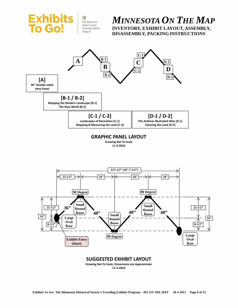
[B-1 / B-2] Mapping the Modern Landscape [B-1]
The New World [B-2]
[C-1 / C-2] Landscapes of Recreation [C-1]
Mapping & Measuring the Land [C-2]
[D-1 / D-2] The Andreas Illustrated Atlas [D-1]
Claiming the Land [D-2]
[A] 36” Double-sided
Intro Panel
B A C
D
B-1
B-2
C-1
C-2
D-1
D-2
36”
90 Degree
48” 48”
90 Degree
90 Degree
Large Oval Base
Small Round Bases
Small Round Bases
Small Round Bases 48”
SUGGESTED EXHIBIT LAYOUT Drawing Not To Scale, Dimensions are Approximate
11-3-2010
GRAPHIC PANEL LAYOUT Drawing Not To Scale
11-3-2010
25-1/2”
25-1/2” 34” 34” 34”
34” 34”
127-1/2” (10’-7-1/2”)
8-1/2” 8-1/2”
25-1/2”
Exhibit Entry (Start)
Large Oval Base
MINNESOTA ON THE MAP INVENTORY, EXHIBIT LAYOUT, ASSEMBLY, DISASSEMBLY, PACKING INSTRUCTIONS
Exhibits To Go! The Minnesota Historical Society’s Traveling Exhibits Program – MN ON THE MAP 10-4-2011 Page 7 of 35
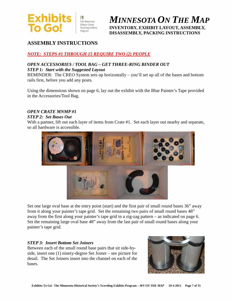
ASSEMBLY INSTRUCTIONS NOTE: STEPS #1 THROUGH 15 REQUIRE TWO (2) PEOPLE OPEN ACCESSORIES / TOOL BAG – GET THREE-RING BINDER OUT STEP 1: Start with the Suggested Layout REMINDER: The CREO System sets up horizontally – you’ll set up all of the bases and bottom rails first, before you add any posts. Using the dimensions shown on page 6, lay out the exhibit with the Blue Painter’s Tape provided in the Accessories/Tool Bag. OPEN CRATE MNMP #1 STEP 2: Set Bases Out With a partner, lift out each layer of items from Crate #1. Set each layer out nearby and separate, so all hardware is accessible. Set one large oval base at the entry point (start) and the first pair of small round bases 36” away from it along your painter’s tape grid. Set the remaining two pairs of small round bases 48” away from the first along your painter’s tape grid in a zig-zag pattern – as indicated on page 6. Set the remaining large oval base 48” away from the last pair of small round bases along your painter’s tape grid. STEP 3: Insert Bottom Set Joiners Between each of the small round base pairs that sit side-by-side, insert one (1) ninety-degree Set Joiner – see picture for detail. The Set Joiners insert into the channel on each of the bases.
MINNESOTA ON THE MAP INVENTORY, EXHIBIT LAYOUT, ASSEMBLY, DISASSEMBLY, PACKING INSTRUCTIONS
Exhibits To Go! The Minnesota Historical Society’s Traveling Exhibits Program – MN ON THE MAP 10-4-2011 Page 8 of 35
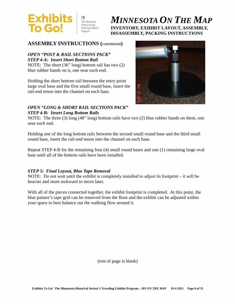
ASSEMBLY INSTRUCTIONS ( CONTINUED) OPEN “POST & RAIL SECTIONS PACK” STEP 4-A: Insert Short Bottom Rail NOTE: The short (36” long) bottom rail has two (2) blue rubber bands on it, one near each end. Holding the short bottom rail between the entry point large oval base and the first small round base, insert the rail-end tenon into the channel on each base. OPEN “LONG & SHORT RAIL SECTIONS PACK” STEP 4-B: Insert Long Bottom Rails NOTE: The three (3) long (48” long) bottom rails have two (2) blue rubber bands on them, one near each end. Holding one of the long bottom rails between the second small round base and the third small round base, insert the rail-end tenon into the channel on each base. Repeat STEP 4-B for the remaining four (4) small round bases and one (1) remaining large oval base until all of the bottom rails have been installed. STEP 5: Final Layout, Blue Tape Removal NOTE: Do not wait until the exhibit is completely installed to adjust its footprint – it will be heavier and more awkward to move later. With all of the pieces connected together, the exhibit footprint is completed. At this point, the blue painter’s tape grid can be removed from the floor and the exhibit can be adjusted within your space to best balance out the walking flow around it.
(rest of page is blank)
MINNESOTA ON THE MAP INVENTORY, EXHIBIT LAYOUT, ASSEMBLY, DISASSEMBLY, PACKING INSTRUCTIONS
Exhibits To Go! The Minnesota Historical Society’s Traveling Exhibits Program – MN ON THE MAP 10-4-2011 Page 9 of 35
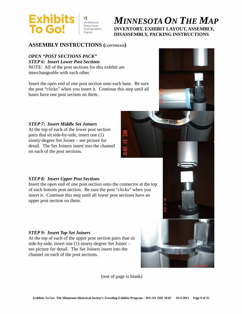
ASSEMBLY INSTRUCTIONS ( CONTINUED) OPEN “POST SECTIONS PACK” STEP 6: Insert Lower Post Sections NOTE: All of the post sections for this exhibit are interchangeable with each other. Insert the open end of one post section onto each base. Be sure the post “clicks” when you insert it. Continue this step until all bases have one post section on them.
STEP 7: Insert Middle Set Joiners At the top of each of the lower post section pairs that sit side-by-side, insert one (1) ninety-degree Set Joiner – see picture for detail. The Set Joiners insert into the channel on each of the post sections. STEP 8: Insert Upper Post Sections Insert the open end of one post section onto the connector at the top of each bottom post section. Be sure the post “clicks” when you insert it. Continue this step until all lower post sections have an upper post section on them.
STEP 9: Insert Top Set Joiners At the top of each of the upper post section pairs that sit side-by-side, insert one (1) ninety-degree Set Joiner – see picture for detail. The Set Joiners insert into the channel on each of the post sections.
(rest of page is blank)

MINNESOTA ON THE MAP INVENTORY, EXHIBIT LAYOUT, ASSEMBLY, DISASSEMBLY, PACKING INSTRUCTIONS
Exhibits To Go! The Minnesota Historical Society’s Traveling Exhibits Program – MN ON THE MAP 10-4-2011 Page 10 of 35
ASSEMBLY INSTRUCTIONS ( CONTINUED) STEP 10-A: Insert Short Top Rail NOTE: The short (36” long) top rail does not have any blue rubber bands on it. Holding the short top rail between the upper post sections at the entry point large oval base and the first small round base, insert the rail-end tenon into the channel on each upper post section. STEP 10-B: Insert Long Top Rails NOTE: The three (3) long (48” long) top rails do not have any blue rubber bands on them. Holding one of the long top rails between the upper post sections already installed on the second small round base and the third small round base, insert the rail-end tenon into the channel on each upper post section. Repeat STEP 10-B for the remaining upper post sections already installed on the four (4) remaining small round bases and one (1) remaining large oval base until all of the top rails have been installed. STEP 11: Add Top Cap to Each Post Insert the top caps on each post. Be sure the top cap “clicks” when you insert it. Continue this step until all the top caps have been installed op the top of all of the exposed upper post sections. Tighten the top caps by turning the black cone until snug (“righty-tighty”), but DO NOT OVERTIGHTEN.
(rest of page is blank)
MINNESOTA ON THE MAP INVENTORY, EXHIBIT LAYOUT, ASSEMBLY, DISASSEMBLY, PACKING INSTRUCTIONS
Exhibits To Go! The Minnesota Historical Society’s Traveling Exhibits Program – MN ON THE MAP 10-4-2011 Page 11 of 35
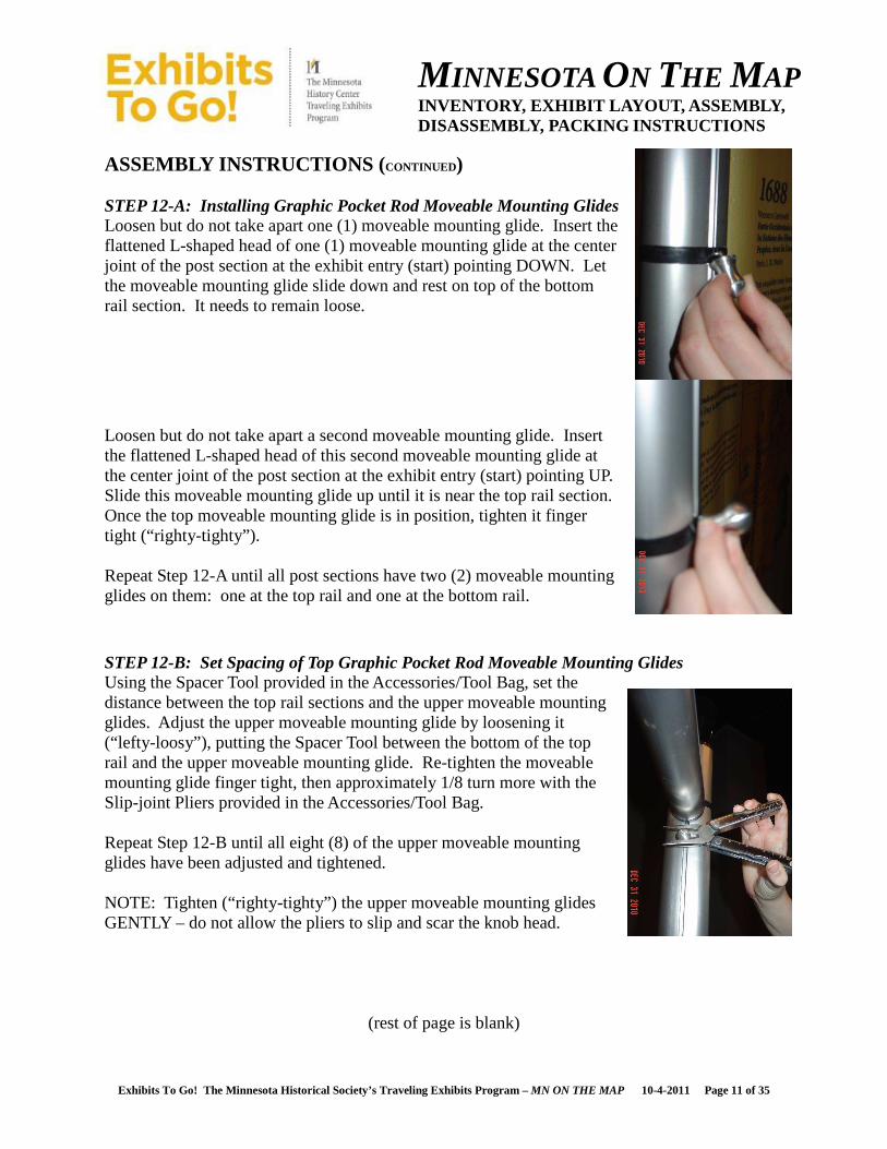
ASSEMBLY INSTRUCTIONS ( CONTINUED) STEP 12-A: Installing Graphic Pocket Rod Moveable Mounting Glides Loosen but do not take apart one (1) moveable mounting glide. Insert the flattened L-shaped head of one (1) moveable mounting glide at the center joint of the post section at the exhibit entry (start) pointing DOWN. Let the moveable mounting glide slide down and rest on top of the bottom rail section. It needs to remain loose.
Loosen but do not take apart a second moveable mounting glide. Insert the flattened L-shaped head of this second moveable mounting glide at the center joint of the post section at the exhibit entry (start) pointing UP. Slide this moveable mounting glide up until it is near the top rail section. Once the top moveable mounting glide is in position, tighten it finger tight (“righty-tighty”). Repeat Step 12-A until all post sections have two (2) moveable mounting glides on them: one at the top rail and one at the bottom rail. STEP 12-B: Set Spacing of Top Graphic Pocket Rod Moveable Mounting Glides Using the Spacer Tool provided in the Accessories/Tool Bag, set the distance between the top rail sections and the upper moveable mounting glides. Adjust the upper moveable mounting glide by loosening it (“lefty-loosy”), putting the Spacer Tool between the bottom of the top rail and the upper moveable mounting glide. Re-tighten the moveable mounting glide finger tight, then approximately 1/8 turn more with the Slip-joint Pliers provided in the Accessories/Tool Bag. Repeat Step 12-B until all eight (8) of the upper moveable mounting glides have been adjusted and tightened. NOTE: Tighten (“righty-tighty”) the upper moveable mounting glides GENTLY – do not allow the pliers to slip and scar the knob head.
(rest of page is blank)
MINNESOTA ON THE MAP INVENTORY, EXHIBIT LAYOUT, ASSEMBLY, DISASSEMBLY, PACKING INSTRUCTIONS
Exhibits To Go! The Minnesota Historical Society’s Traveling Exhibits Program – MN ON THE MAP 10-4-2011 Page 12 of 35
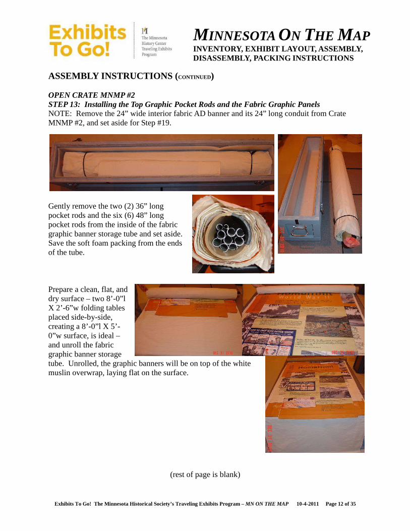
ASSEMBLY INSTRUCTIONS ( CONTINUED) OPEN CRATE MNMP #2 STEP 13: Installing the Top Graphic Pocket Rods and the Fabric Graphic Panels NOTE: Remove the 24” wide interior fabric AD banner and its 24” long conduit from Crate MNMP #2, and set aside for Step #19.
Gently remove the two (2) 36” long pocket rods and the six (6) 48” long pocket rods from the inside of the fabric graphic banner storage tube and set aside. Save the soft foam packing from the ends of the tube. Prepare a clean, flat, and dry surface – two 8’-0”l X 2’-6”w folding tables placed side-by-side, creating a 8’-0”l X 5’-0”w surface, is ideal – and unroll the fabric graphic banner storage tube. Unrolled, the graphic banners will be on top of the white muslin overwrap, laying flat on the surface.
(rest of page is blank)

MINNESOTA ON THE MAP INVENTORY, EXHIBIT LAYOUT, ASSEMBLY, DISASSEMBLY, PACKING INSTRUCTIONS
Exhibits To Go! The Minnesota Historical Society’s Traveling Exhibits Program – MN ON THE MAP 10-4-2011 Page 13 of 35
ASSEMBLY INSTRUCTIONS ( CONTINUED) OPEN CRATE MNMP #2 STEP 13: Installing the Top Graphic Pocket Rods and the Fabric Graphic Panels (continued) Starting with the 35-1/2” wide fabric graphic panel, place one of the 36” long pocket rods at the inside top of the fabric loop. Next, put the un-notched end of the pocket rod over the upper moveable mounting glide on the “Exhibit Entry/Start” post. Now place the notched end of the pocket rod over the upper moveable mounting glide at the next post section. Make sure to rotate the pocket rod so the notch is facing DOWN. Repeat Step 13 by installing the 47-1/2”wide fabric graphic panels and the 48” long top pocket rods and until all of the fabric banner panels have been hung on their top pocket rods. NOTE: Refer to the “Graphic Panel Layout” on page 4 of this manual for the correct order of the fabric graphic banners. NOTE: Both of the 36” long pocket rods are the same and interchangeable. All of the 48” long pocket rods are the same and interchangeable.
(rest of page is blank)
MINNESOTA ON THE MAP INVENTORY, EXHIBIT LAYOUT, ASSEMBLY, DISASSEMBLY, PACKING INSTRUCTIONS
Exhibits To Go! The Minnesota Historical Society’s Traveling Exhibits Program – MN ON THE MAP 10-4-2011 Page 14 of 35
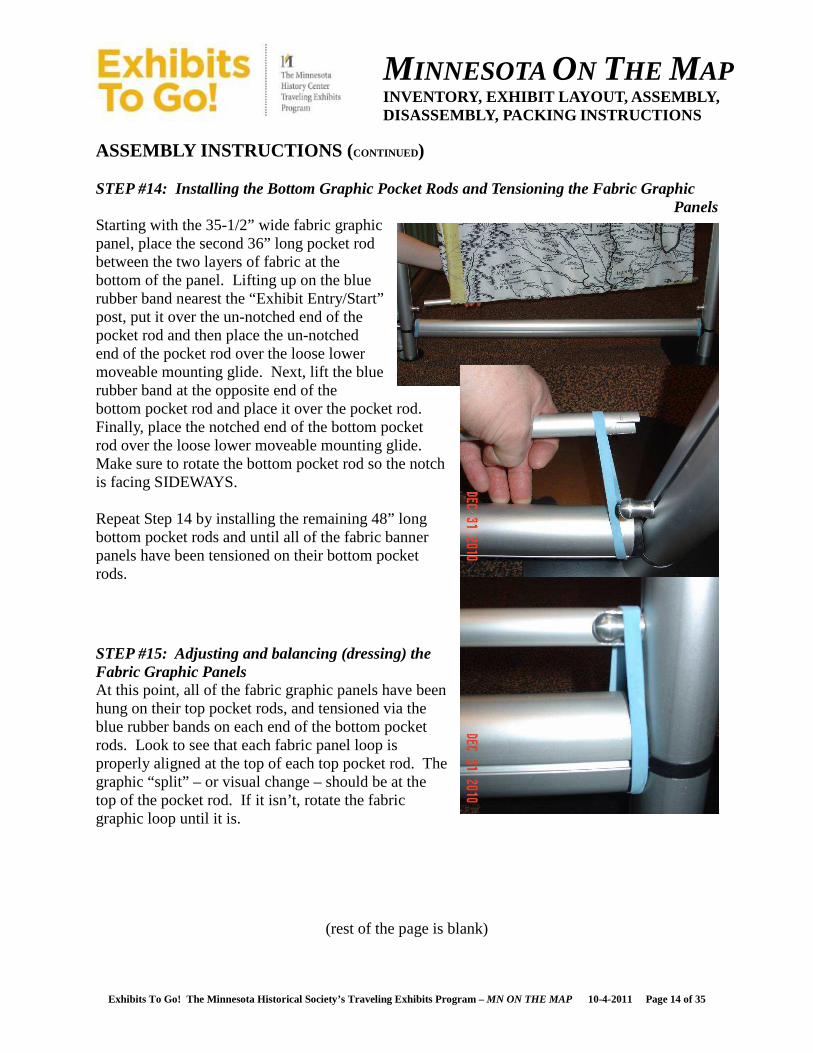
ASSEMBLY INSTRUCTIONS ( CONTINUED) STEP #14: Installing the Bottom Graphic Pocket Rods and Tensioning the Fabric Graphic
Panels Starting with the 35-1/2” wide fabric graphic panel, place the second 36” long pocket rod between the two layers of fabric at the bottom of the panel. Lifting up on the blue rubber band nearest the “Exhibit Entry/Start” post, put it over the un-notched end of the pocket rod and then place the un-notched end of the pocket rod over the loose lower moveable mounting glide. Next, lift the blue rubber band at the opposite end of the bottom pocket rod and place it over the pocket rod. Finally, place the notched end of the bottom pocket rod over the loose lower moveable mounting glide. Make sure to rotate the bottom pocket rod so the notch is facing SIDEWAYS. Repeat Step 14 by installing the remaining 48” long bottom pocket rods and until all of the fabric banner panels have been tensioned on their bottom pocket rods. STEP #15: Adjusting and balancing (dressing) the Fabric Graphic Panels At this point, all of the fabric graphic panels have been hung on their top pocket rods, and tensioned via the blue rubber bands on each end of the bottom pocket rods. Look to see that each fabric panel loop is properly aligned at the top of each top pocket rod. The graphic “split” – or visual change – should be at the top of the pocket rod. If it isn’t, rotate the fabric graphic loop until it is.
(rest of the page is blank)
MINNESOTA ON THE MAP INVENTORY, EXHIBIT LAYOUT, ASSEMBLY, DISASSEMBLY, PACKING INSTRUCTIONS
Exhibits To Go! The Minnesota Historical Society’s Traveling Exhibits Program – MN ON THE MAP 10-4-2011 Page 15 of 35
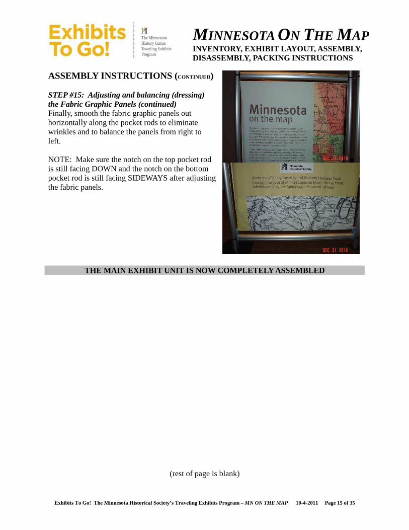
ASSEMBLY INSTRUCTIONS ( CONTINUED) STEP #15: Adjusting and balancing (dressing) the Fabric Graphic Panels (continued) Finally, smooth the fabric graphic panels out horizontally along the pocket rods to eliminate wrinkles and to balance the panels from right to left. NOTE: Make sure the notch on the top pocket rod is still facing DOWN and the notch on the bottom pocket rod is still facing SIDEWAYS after adjusting the fabric panels.
THE MAIN EXHIBIT UNIT IS NOW COMPLETELY ASSEMBLED
(rest of page is blank)
MINNESOTA ON THE MAP INVENTORY, EXHIBIT LAYOUT, ASSEMBLY, DISASSEMBLY, PACKING INSTRUCTIONS
Exhibits To Go! The Minnesota Historical Society’s Traveling Exhibits Program – MN ON THE MAP 10-4-2011 Page 16 of 35
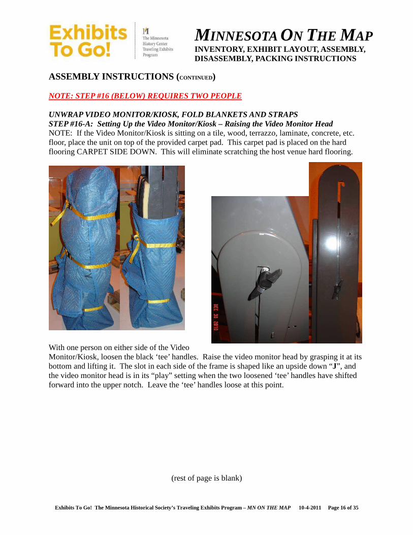
ASSEMBLY INSTRUCTIONS ( CONTINUED) NOTE: STEP #16 (BELOW) REQUIRES TWO PEOPLE UNWRAP VIDEO MONITOR/KIOSK, FOLD BLANKETS AND STRAPS STEP #16-A: Setting Up the Video Monitor/Kiosk – Raising the Video Monitor Head NOTE: If the Video Monitor/Kiosk is sitting on a tile, wood, terrazzo, laminate, concrete, etc. floor, place the unit on top of the provided carpet pad. This carpet pad is placed on the hard flooring CARPET SIDE DOWN. This will eliminate scratching the host venue hard flooring.
With one person on either side of the Video Monitor/Kiosk, loosen the black ‘tee’ handles. Raise the video monitor head by grasping it at its bottom and lifting it. The slot in each side of the frame is shaped like an upside down “J”, and the video monitor head is in its “play” setting when the two loosened ‘tee’ handles have shifted forward into the upper notch. Leave the ‘tee’ handles loose at this point.
(rest of page is blank)

MINNESOTA ON THE MAP INVENTORY, EXHIBIT LAYOUT, ASSEMBLY, DISASSEMBLY, PACKING INSTRUCTIONS
Exhibits To Go! The Minnesota Historical Society’s Traveling Exhibits Program – MN ON THE MAP 10-4-2011 Page 17 of 35
ASSEMBLY INSTRUCTIONS ( CONTINUED) STEP #16-B: Setting up the Video Monitor/Kiosk – Tilting the Video Monitor Head Using the provided flashlight, pivot the video monitor head to the desired angle (there are numerous settings available). While one person holds the video monitor head at the desired angle, use the flashlight to align the threaded hole in one side of the kiosk frame with the appropriate unthreaded hole in the video monitor head. Thread one of the socket-head allen screws into the kiosk frame hole. Using the allen-head wrench, continue to thread the socket-head allen screw into the kiosk frame until it is flush on the outer face. Repeat this process for the other side of the kiosk frame. After the two socket-head allen screws are in place, tighten the ‘tee’ handles snugly. STEP #17: Powering up the Video Monitor/Kiosk Remove the volume control transport cover by un-velcroing the strap from the video monitor head. Re-wrap the Velcro around the volume control transport cover for storage. Remove the video monitor screen transport cover by un-velcroing the straps from the video monitor head. Re-wrap the Velcro around the screen transport cover for storage. Using one or more of the provided black extension cords, plug the male end of the cord into the host venue power source (110 volt standard household outlet), and then plug the female end of the cord into the socket at the back of the video monitor head. The unit will start up on its own, and will go through a series of screens until it readies itself on the ‘welcome’ screen.
(rest of page is blank)
Socket-head Allen-screw
MINNESOTA ON THE MAP INVENTORY, EXHIBIT LAYOUT, ASSEMBLY, DISASSEMBLY, PACKING INSTRUCTIONS
Exhibits To Go! The Minnesota Historical Society’s Traveling Exhibits Program – MN ON THE MAP 10-4-2011 Page 18 of 35
ASSEMBLY INSTRUCTIONS ( CONTINUED) STEP #17: Powering up the Video Monitor/Kiosk (continued) With a partner, gently slide the video monitor/kiosk close to its final position to determine what will be needed to clean up (dress) the power cord(s). Using six (6) small black zip-ties, secure the power cord from the back of the video monitor head to the kiosk floor base. Start at the upper hole in the frame leg, and create a gentle loop in the cord at the back of the video monitor head. Secure the power cord in each of the remaining holes, keeping the cord smooth between each hole. Use the side-cutter to trim off the excess tail from each of the zip-ties. After the power cord has been secured to the leg of the video monitor/kiosk, gently slide the unit into its final position and continue to clean up (dress) the power cord(s) along the floor. Use the provided black cord cover(s) as needed, particularly if the cord has to be in a walkway. Secure the cord cover(s) in place using the black fabric (gaffer’s) tape provided. NOTE: The black fabric (gaffer’s) tape may leave a slight sticky residue on hard floor surfaces. This can be easily removed with glass cleaner; however, make sure glass cleaner WILL NOT HARM YOUR FLOOR FINISH BEFORE USING.
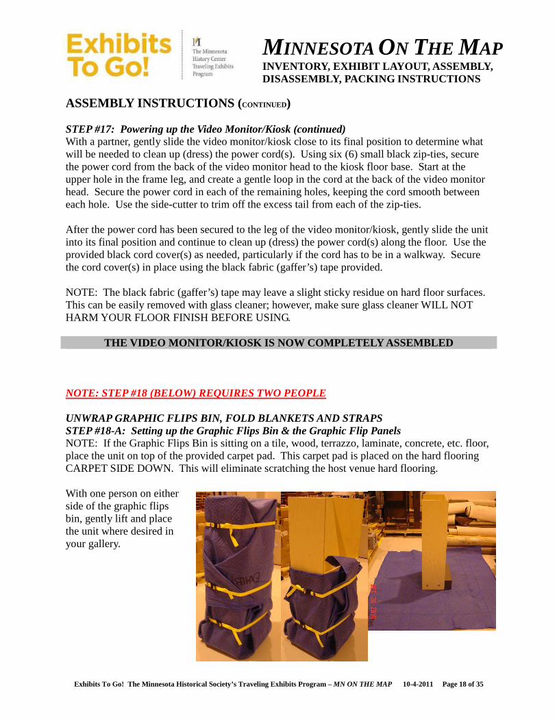
THE VIDEO MONITOR/KIOSK IS NOW COMPLETELY ASSEMBLED NOTE: STEP #18 (BELOW) REQUIRES TWO PEOPLE UNWRAP GRAPHIC FLIPS BIN, FOLD BLANKETS AND STRAPS STEP #18-A: Setting up the Graphic Flips Bin & the Graphic Flip Panels NOTE: If the Graphic Flips Bin is sitting on a tile, wood, terrazzo, laminate, concrete, etc. floor, place the unit on top of the provided carpet pad. This carpet pad is placed on the hard flooring CARPET SIDE DOWN. This will eliminate scratching the host venue hard flooring. With one person on either side of the graphic flips bin, gently lift and place the unit where desired in your gallery.
MINNESOTA ON THE MAP INVENTORY, EXHIBIT LAYOUT, ASSEMBLY, DISASSEMBLY, PACKING INSTRUCTIONS
Exhibits To Go! The Minnesota Historical Society’s Traveling Exhibits Program – MN ON THE MAP 10-4-2011 Page 19 of 35
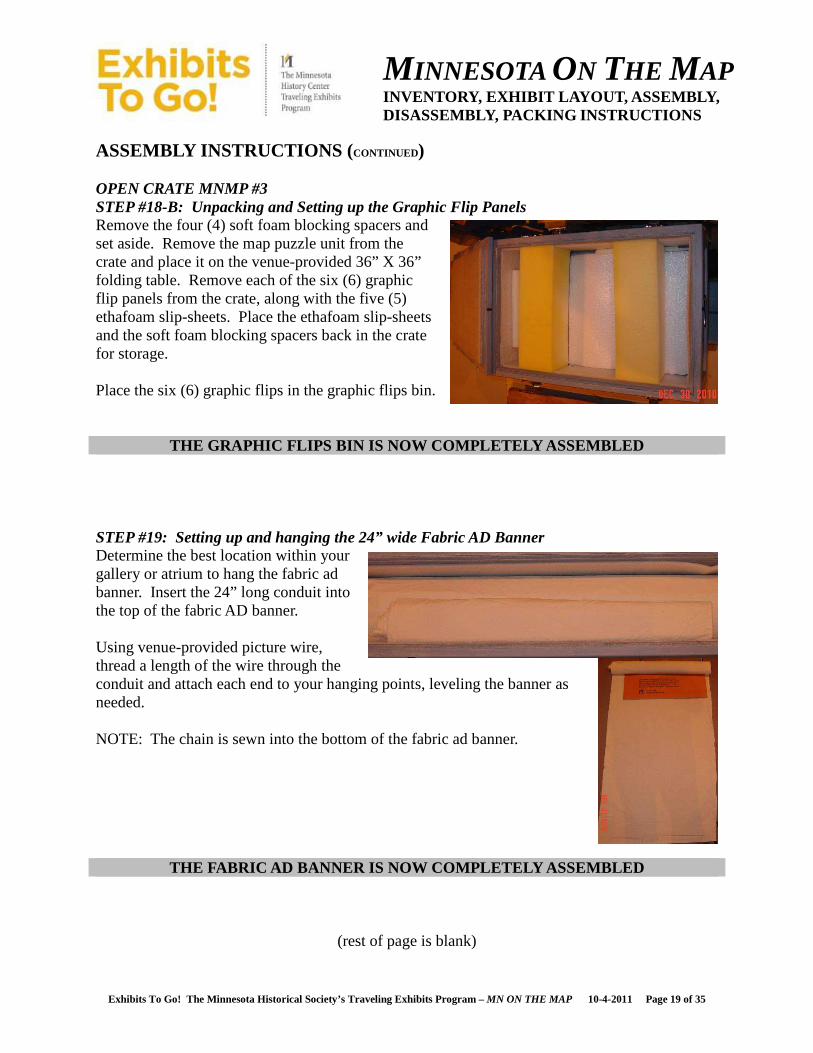
ASSEMBLY INSTRUCTIONS ( CONTINUED) OPEN CRATE MNMP #3 STEP #18-B: Unpacking and Setting up the Graphic Flip Panels Remove the four (4) soft foam blocking spacers and set aside. Remove the map puzzle unit from the crate and place it on the venue-provided 36” X 36” folding table. Remove each of the six (6) graphic flip panels from the crate, along with the five (5) ethafoam slip-sheets. Place the ethafoam slip-sheets and the soft foam blocking spacers back in the crate for storage. Place the six (6) graphic flips in the graphic flips bin.
THE GRAPHIC FLIPS BIN IS NOW COMPLETELY ASSEMBLED STEP #19: Setting up and hanging the 24” wide Fabric AD Banner Determine the best location within your gallery or atrium to hang the fabric ad banner. Insert the 24” long conduit into the top of the fabric AD banner. Using venue-provided picture wire, thread a length of the wire through the conduit and attach each end to your hanging points, leveling the banner as needed. NOTE: The chain is sewn into the bottom of the fabric ad banner.
THE FABRIC AD BANNER IS NOW COMPLETELY ASSEMBLED
(rest of page is blank)
MINNESOTA ON THE MAP INVENTORY, EXHIBIT LAYOUT, ASSEMBLY, DISASSEMBLY, PACKING INSTRUCTIONS
Exhibits To Go! The Minnesota Historical Society’s Traveling Exhibits Program – MN ON THE MAP 10-4-2011 Page 20 of 35
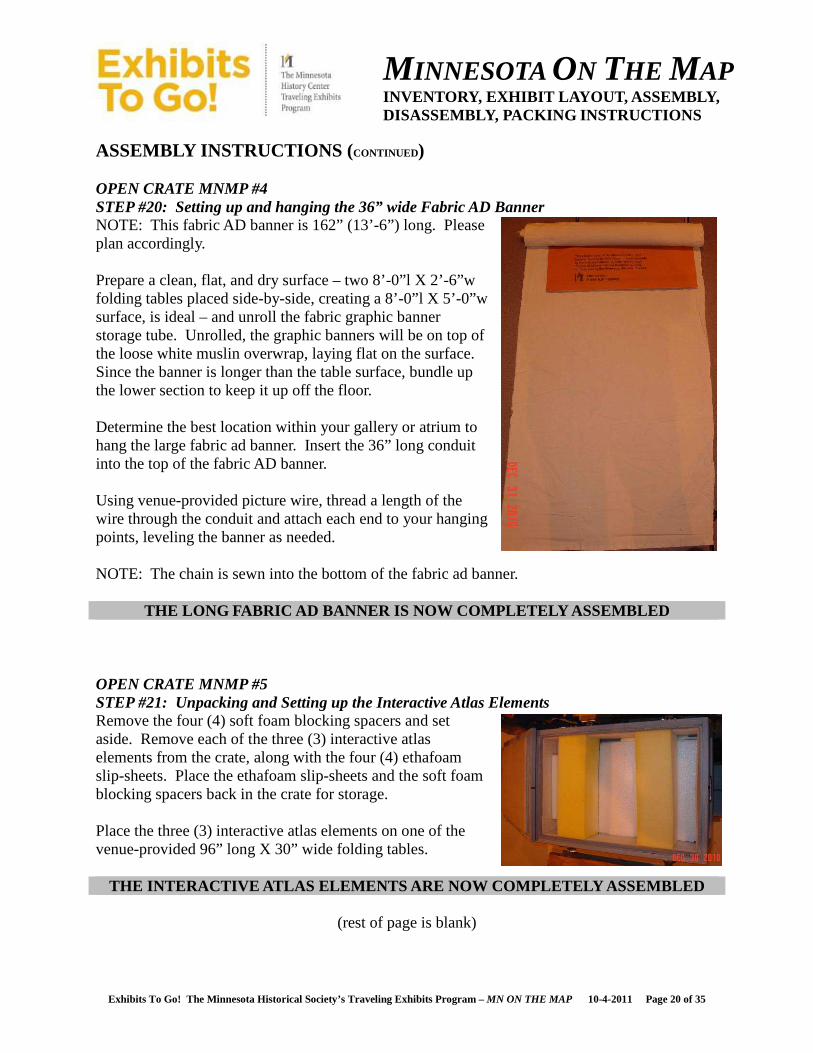
ASSEMBLY INSTRUCTIONS ( CONTINUED) OPEN CRATE MNMP #4 STEP #20: Setting up and hanging the 36” wide Fabric AD Banner NOTE: This fabric AD banner is 162” (13’-6”) long. Please plan accordingly. Prepare a clean, flat, and dry surface – two 8’-0”l X 2’-6”w folding tables placed side-by-side, creating a 8’-0”l X 5’-0”w surface, is ideal – and unroll the fabric graphic banner storage tube. Unrolled, the graphic banners will be on top of the loose white muslin overwrap, laying flat on the surface. Since the banner is longer than the table surface, bundle up the lower section to keep it up off the floor. Determine the best location within your gallery or atrium to hang the large fabric ad banner. Insert the 36” long conduit into the top of the fabric AD banner. Using venue-provided picture wire, thread a length of the wire through the conduit and attach each end to your hanging points, leveling the banner as needed. NOTE: The chain is sewn into the bottom of the fabric ad banner.
THE LONG FABRIC AD BANNER IS NOW COMPLETELY ASSEMBL ED OPEN CRATE MNMP #5 STEP #21: Unpacking and Setting up the Interactive Atlas Elements Remove the four (4) soft foam blocking spacers and set aside. Remove each of the three (3) interactive atlas elements from the crate, along with the four (4) ethafoam slip-sheets. Place the ethafoam slip-sheets and the soft foam blocking spacers back in the crate for storage. Place the three (3) interactive atlas elements on one of the venue-provided 96” long X 30” wide folding tables.
THE INTERACTIVE ATLAS ELEMENTS ARE NOW COMPLETELY A SSEMBLED
(rest of page is blank)
MINNESOTA ON THE MAP INVENTORY, EXHIBIT LAYOUT, ASSEMBLY, DISASSEMBLY, PACKING INSTRUCTIONS
Exhibits To Go! The Minnesota Historical Society’s Traveling Exhibits Program – MN ON THE MAP 10-4-2011 Page 21 of 35
CONDITION REPORTING & CRATE STORAGE INSTRUCTIONS CONDITION REPORTING Once the exhibit is completely assembled and operating, please take the time to clean it. The fabric graphic panels require no care except for gently brushing any surface dust from them. If the framing, the graphic flips bin, or the video monitor/kiosk frame needs cleaning, use wipes from the box lightly dampened with Plexi cleaner. DO NOT spray the cleaner onto the surfaces, spray it onto the wipes. Inspect the exhibit and fill out the Incoming Condition Reporting Form at this time. CRATE STORAGE The exhibit crates, packing materials, packing blankets, and tools all must be stored in a clean, dry, heated location free from vermin and pests. Inspect the crates, packing materials, packing blankets and tools at this time to be able to fill out the Incoming Condition Reporting Form at this time.
(rest of page is blank)
MINNESOTA ON THE MAP INVENTORY, EXHIBIT LAYOUT, ASSEMBLY, DISASSEMBLY, PACKING INSTRUCTIONS
Exhibits To Go! The Minnesota Historical Society’s Traveling Exhibits Program – MN ON THE MAP 10-4-2011 Page 22 of 35
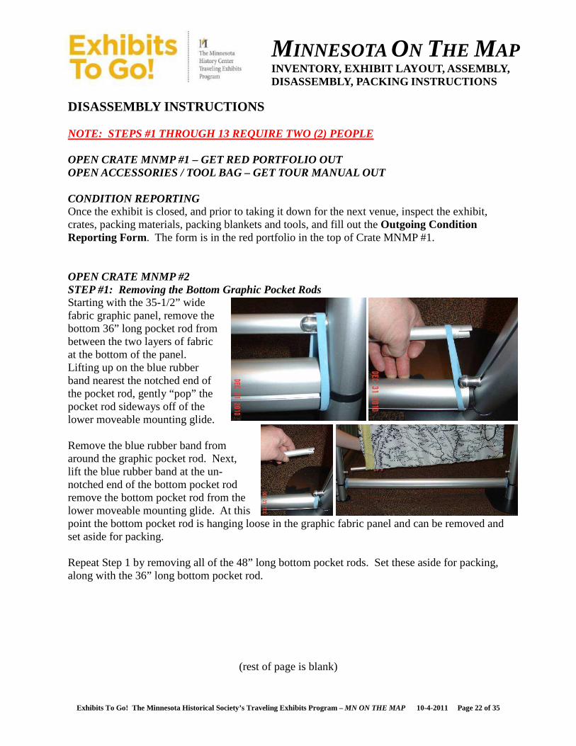
DISASSEMBLY INSTRUCTIONS NOTE: STEPS #1 THROUGH 13 REQUIRE TWO (2) PEOPLE OPEN CRATE MNMP #1 – GET RED PORTFOLIO OUT OPEN ACCESSORIES / TOOL BAG – GET TOUR MANUAL OUT CONDITION REPORTING Once the exhibit is closed, and prior to taking it down for the next venue, inspect the exhibit, crates, packing materials, packing blankets and tools, and fill out the Outgoing Condition Reporting Form. The form is in the red portfolio in the top of Crate MNMP #1. OPEN CRATE MNMP #2 STEP #1: Removing the Bottom Graphic Pocket Rods Starting with the 35-1/2” wide fabric graphic panel, remove the bottom 36” long pocket rod from between the two layers of fabric at the bottom of the panel. Lifting up on the blue rubber band nearest the notched end of the pocket rod, gently “pop” the pocket rod sideways off of the lower moveable mounting glide. Remove the blue rubber band from around the graphic pocket rod. Next, lift the blue rubber band at the un-notched end of the bottom pocket rod remove the bottom pocket rod from the lower moveable mounting glide. At this point the bottom pocket rod is hanging loose in the graphic fabric panel and can be removed and set aside for packing. Repeat Step 1 by removing all of the 48” long bottom pocket rods. Set these aside for packing, along with the 36” long bottom pocket rod.
(rest of page is blank)

MINNESOTA ON THE MAP INVENTORY, EXHIBIT LAYOUT, ASSEMBLY, DISASSEMBLY, PACKING INSTRUCTIONS
Exhibits To Go! The Minnesota Historical Society’s Traveling Exhibits Program – MN ON THE MAP 10-4-2011 Page 23 of 35
DISASSEMBLY INSTRUCTIONS ( CONTINUED) STEP 2-A: Removing the Top Graphic Pocket Rods and the Fabric Graphic Panels Prepare a clean, flat, and dry surface – two 8’-0”L x 2’-6”w folding tables placed side-by-side, creating a 8’-0”l X 5’-0”w surface, is ideal – and unroll the graphic banner storage tube. Unrolled, the graphic banners will be lie on top of the white muslin overwrap, laying flat on the surface. Starting with the last 47-1/2” wide fabric graphic panel (pair D-1 “The Andreas Illustrated Atlas” and D-2 “Claiming the Land”), gently gather the fabric panel to the center of the top pocket rod. Gently “pop” the top pocket rod up off the upper moveable mounting glide and then gently pull the upper pocket rod horizontally off the other upper moveable mounting glide. The fabric graphic panel and the top pocket rod are now out of the exhibit frame and the top pocket rod can be removed from the fabric graphic panel. Set the top pocket rod aside for packing and with a partner, lay the fabric graphic panel on the white muslin overwrap, centering it from side to side, with the “The Andreas Illustrated Atlas” (D-1) side facing up and the top of the panel next to the edge of the cardboard tube where the muslin overwrap is attached to it. Repeat this step in “reverse order” (C-1/C-2, B-1/B-2, then A-1/A-2).
STEP 2-B: Removing the Graphic Pocket Rod Moveable Mounting Glides Loosen (“lefty-loosy”) but do not take apart all sixteen (16) moveable mounting glides. Slide the eight (8) lower moveable mounting glides up to the center joint of each post section and remove them. Slide the eight (8) upper moveable mounting glides down to the center joint of each post section and remove them. Put all sixteen (16) of the graphic pocket rod moveable mounting glides in their plastic bag in layer #3 of Crate #MNMP #1.
(rest of page is blank)
MINNESOTA ON THE MAP INVENTORY, EXHIBIT LAYOUT, ASSEMBLY, DISASSEMBLY, PACKING INSTRUCTIONS
Exhibits To Go! The Minnesota Historical Society’s Traveling Exhibits Program – MN ON THE MAP 10-4-2011 Page 24 of 35
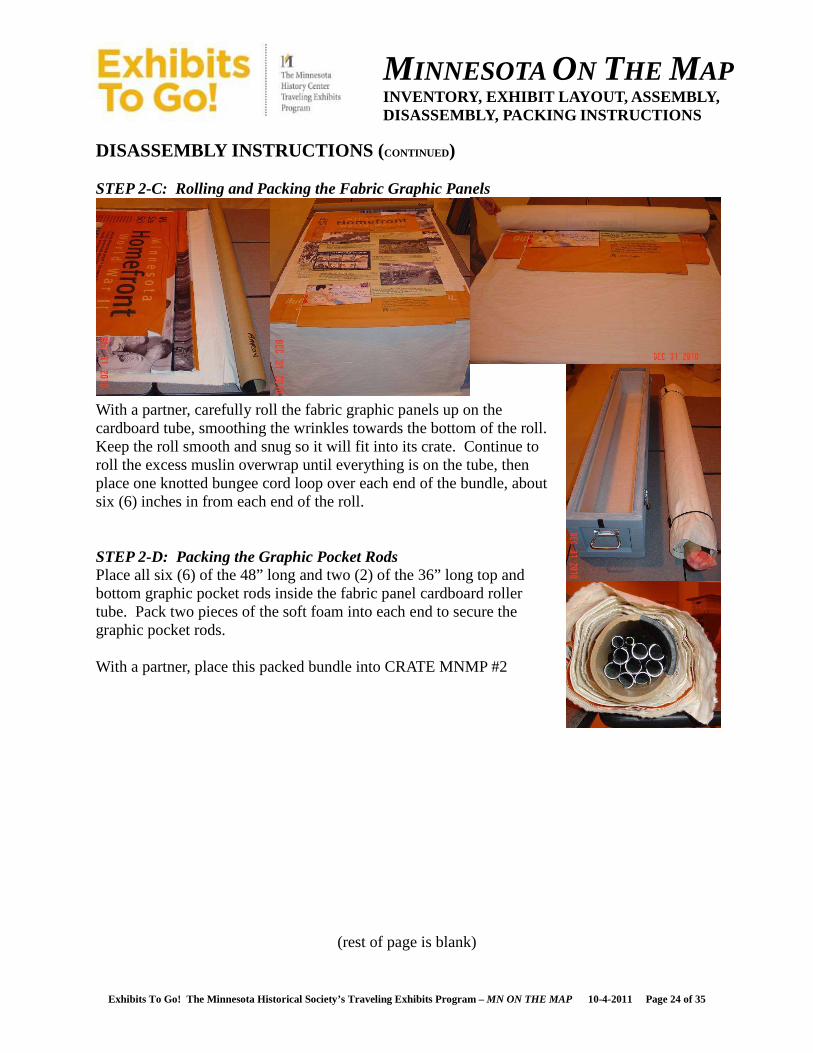
DISASSEMBLY INSTRUCTIONS ( CONTINUED) STEP 2-C: Rolling and Packing the Fabric Graphic Panels
With a partner, carefully roll the fabric graphic panels up on the cardboard tube, smoothing the wrinkles towards the bottom of the roll. Keep the roll smooth and snug so it will fit into its crate. Continue to roll the excess muslin overwrap until everything is on the tube, then place one knotted bungee cord loop over each end of the bundle, about six (6) inches in from each end of the roll. STEP 2-D: Packing the Graphic Pocket Rods Place all six (6) of the 48” long and two (2) of the 36” long top and bottom graphic pocket rods inside the fabric panel cardboard roller tube. Pack two pieces of the soft foam into each end to secure the graphic pocket rods. With a partner, place this packed bundle into CRATE MNMP #2
(rest of page is blank)

MINNESOTA ON THE MAP INVENTORY, EXHIBIT LAYOUT, ASSEMBLY, DISASSEMBLY, PACKING INSTRUCTIONS
Exhibits To Go! The Minnesota Historical Society’s Traveling Exhibits Program – MN ON THE MAP 10-4-2011 Page 25 of 35
DISASSEMBLY INSTRUCTIONS ( CONTINUED) STEP 3: Packing the 24” wide Fabric AD Banner Retrieve the 24” wide interior fabric graphic AD banner, remove the top hanging conduit and any/all of the Venue’s hanging hardware from it. Layout the loose piece of muslin from Crate MNHF #2, on one 8’-0”L x 2’-6”w folding table, and lay the fabric AD banner on top, making sure that it is centered from side to side, and that the top of the banner is at one edge of the muslin. Carefully roll the fabric graphic panel up inside the muslin, smoothing the wrinkles towards the bottom of the roll. Keep the roll smooth and snug so it will fit into its crate, on top of the larger fabric banner roll. Continue to roll the excess muslin overwrap onto itself. Place this packed bundle into CRATE MNMP #2. Place the 24” long piece of conduit loosely into CRATE MNMP #2.
CRATE MNMP #2 CAN BE CLOSED AND SET ASIDE
(rest of page is blank)
MINNESOTA ON THE MAP INVENTORY, EXHIBIT LAYOUT, ASSEMBLY, DISASSEMBLY, PACKING INSTRUCTIONS
Exhibits To Go! The Minnesota Historical Society’s Traveling Exhibits Program – MN ON THE MAP 10-4-2011 Page 26 of 35
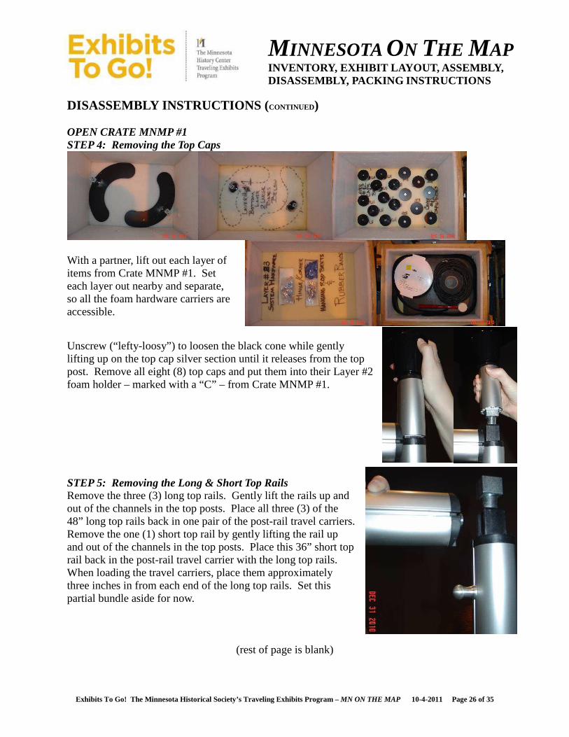
DISASSEMBLY INSTRUCTIONS ( CONTINUED) OPEN CRATE MNMP #1 STEP 4: Removing the Top Caps
With a partner, lift out each layer of items from Crate MNMP #1. Set each layer out nearby and separate, so all the foam hardware carriers are accessible.
Unscrew (“lefty-loosy”) to loosen the black cone while gently lifting up on the top cap silver section until it releases from the top post. Remove all eight (8) top caps and put them into their Layer #2 foam holder – marked with a “C” – from Crate MNMP #1.
STEP 5: Removing the Long & Short Top Rails Remove the three (3) long top rails. Gently lift the rails up and out of the channels in the top posts. Place all three (3) of the 48” long top rails back in one pair of the post-rail travel carriers. Remove the one (1) short top rail by gently lifting the rail up and out of the channels in the top posts. Place this 36” short top rail back in the post-rail travel carrier with the long top rails. When loading the travel carriers, place them approximately three inches in from each end of the long top rails. Set this partial bundle aside for now.
(rest of page is blank)
MINNESOTA ON THE MAP INVENTORY, EXHIBIT LAYOUT, ASSEMBLY, DISASSEMBLY, PACKING INSTRUCTIONS
Exhibits To Go! The Minnesota Historical Society’s Traveling Exhibits Program – MN ON THE MAP 10-4-2011 Page 27 of 35
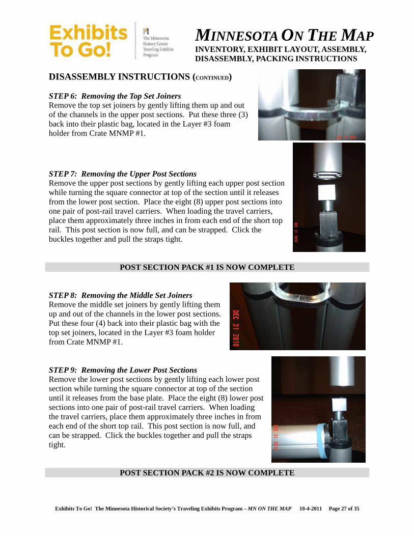
DISASSEMBLY INSTRUCTIONS ( CONTINUED) STEP 6: Removing the Top Set Joiners Remove the top set joiners by gently lifting them up and out of the channels in the upper post sections. Put these three (3) back into their plastic bag, located in the Layer #3 foam holder from Crate MNMP #1.
STEP 7: Removing the Upper Post Sections Remove the upper post sections by gently lifting each upper post section while turning the square connector at top of the section until it releases from the lower post section. Place the eight (8) upper post sections into one pair of post-rail travel carriers. When loading the travel carriers, place them approximately three inches in from each end of the short top rail. This post section is now full, and can be strapped. Click the buckles together and pull the straps tight.
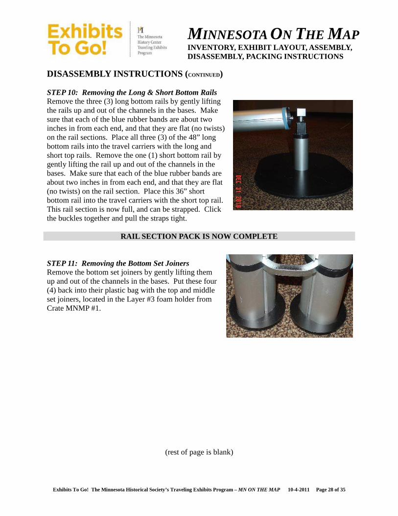
POST SECTION PACK #1 IS NOW COMPLETE STEP 8: Removing the Middle Set Joiners Remove the middle set joiners by gently lifting them up and out of the channels in the lower post sections. Put these four (4) back into their plastic bag with the top set joiners, located in the Layer #3 foam holder from Crate MNMP #1. STEP 9: Removing the Lower Post Sections Remove the lower post sections by gently lifting each lower post section while turning the square connector at top of the section until it releases from the base plate. Place the eight (8) lower post sections into one pair of post-rail travel carriers. When loading the travel carriers, place them approximately three inches in from each end of the short top rail. This post section is now full, and can be strapped. Click the buckles together and pull the straps tight.
POST SECTION PACK #2 IS NOW COMPLETE
MINNESOTA ON THE MAP INVENTORY, EXHIBIT LAYOUT, ASSEMBLY, DISASSEMBLY, PACKING INSTRUCTIONS
Exhibits To Go! The Minnesota Historical Society’s Traveling Exhibits Program – MN ON THE MAP 10-4-2011 Page 28 of 35
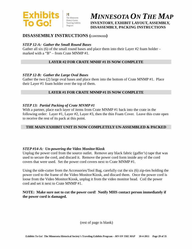
DISASSEMBLY INSTRUCTIONS ( CONTINUED) STEP 10: Removing the Long & Short Bottom Rails Remove the three (3) long bottom rails by gently lifting the rails up and out of the channels in the bases. Make sure that each of the blue rubber bands are about two inches in from each end, and that they are flat (no twists) on the rail sections. Place all three (3) of the 48” long bottom rails into the travel carriers with the long and short top rails. Remove the one (1) short bottom rail by gently lifting the rail up and out of the channels in the bases. Make sure that each of the blue rubber bands are about two inches in from each end, and that they are flat (no twists) on the rail section. Place this 36” short bottom rail into the travel carriers with the short top rail. This rail section is now full, and can be strapped. Click the buckles together and pull the straps tight.
RAIL SECTION PACK IS NOW COMPLETE STEP 11: Removing the Bottom Set Joiners Remove the bottom set joiners by gently lifting them up and out of the channels in the bases. Put these four (4) back into their plastic bag with the top and middle set joiners, located in the Layer #3 foam holder from Crate MNMP #1.
(rest of page is blank)
MINNESOTA ON THE MAP INVENTORY, EXHIBIT LAYOUT, ASSEMBLY, DISASSEMBLY, PACKING INSTRUCTIONS
Exhibits To Go! The Minnesota Historical Society’s Traveling Exhibits Program – MN ON THE MAP 10-4-2011 Page 29 of 35
DISASSEMBLY INSTRUCTIONS ( CONTINUED) STEP 12-A: Gather the Small Round Bases Gather all six (6) of the small round bases and place them into their Layer #2 foam holder – marked with a “B” – from Crate MNMP #1.
LAYER #2 FOR CRATE MNHF #1 IS NOW COMPLETE STEP 12-B: Gather the Large Oval Bases Gather the two (2) large oval bases and place them into the bottom of Crate MNMP #1. Place their Layer #1 foam holder over the top of them.
LAYER #1 FOR CRATE MNMP #1 IS NOW COMPLETE STEP 13: Partial Packing of Crate MNMP #1 With a partner, place each layer of items from Crate MNMP #1 back into the crate in the following order: Layer #1, Layer #2, Layer #3, then the thin Foam Cover. Leave this crate open to receive the rest of its pack at this point.
THE MAIN EXHIBIT UNIT IS NOW COMPLETELY UN-ASSEMBLE D & PACKED STEP #14-A: Un-powering the Video Monitor/Kiosk Unplug the power cord from the source outlet. Remove any black fabric (gaffer’s) tape that was used to secure the cord, and discard it. Remove the power cord form inside any of the cord covers that were used. Set the power cord covers next to Crate MNMP #1. Using the side-cutter from the Accessories/Tool Bag, carefully cut the six (6) zip-ties holding the power cord to the frame of the Video Monitor/Kiosk, and discard them. Once the power cord is loose from the Video Monitor/Kiosk, unplug it from the video monitor head. Coil the power cord and set it next to Crate MNMP #1. NOTE: Make sure not to cut the power cord! Notify MHS contact person immediately if the power cord is damaged.
(rest of page is blank)

MINNESOTA ON THE MAP INVENTORY, EXHIBIT LAYOUT, ASSEMBLY, DISASSEMBLY, PACKING INSTRUCTIONS
Exhibits To Go! The Minnesota Historical Society’s Traveling Exhibits Program – MN ON THE MAP 10-4-2011 Page 30 of 35
DISASSEMBLY INSTRUCTIONS ( CONTINUED) STEP #14-B: Protecting and Lowering the Video Monitor/Kiosk for Transport While one person holds the video monitor head at the desired angle, use the allen-head wrench to remove (“lefty-loosy”) one of the socket-head allen screws in the kiosk frame holes. Repeat this process to remove the socket-head allen screw from the other side of the kiosk frame. Leave the ‘tee’ handles tight at this point. Unwrap the Velcro video monitor screen transport cover straps and hold the cover over the face of the monitor head, centering the cover over the touch screen. Re-wrap the Velcro around the monitor screen transport cover and the monitor head securely so it doesn’t slip or slide.
Unwrap the Velcro volume control transport cover strap and hold the cover over the white volume control knob at the back of the monitor head. Re-wrap the Velcro around the monitor head and the monitor screen transport cover securely so it doesn’t slip off the volume control knob. Loosen the two ‘tee’ handles at either side of the video monitor head, and with one person on either side of the Video Monitor/Kiosk, lift the video monitor head by grasping it at its bottom. The slot in each side of the frame is shaped like an upside down “J”, and the video monitor head is in its “storage” setting when the unit has been lowered back onto the two small pins that fit into holes in the bottom of the video monitor head. Re-tighten the two ‘tee’ handles. NOTE: if the video monitor head can still pivot back and forth in the lowered position, then it is not setting on its transport pins. DO NOT MOVE the unit until it is properly set on its transport pins.
Socket-head Allen-screw
Transport Pin
MINNESOTA ON THE MAP INVENTORY, EXHIBIT LAYOUT, ASSEMBLY, DISASSEMBLY, PACKING INSTRUCTIONS
Exhibits To Go! The Minnesota Historical Society’s Traveling Exhibits Program – MN ON THE MAP 10-4-2011 Page 31 of 35
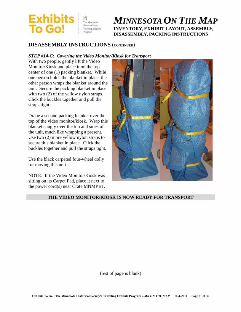
DISASSEMBLY INSTRUCTIONS ( CONTINUED) STEP #14-C: Covering the Video Monitor/Kiosk for Transport With two people, gently lift the Video Monitor/Kiosk and place it on the top center of one (1) packing blanket. While one person holds the blanket in place, the other person wraps the blanket around the unit. Secure the packing blanket in place with two (2) of the yellow nylon straps. Click the buckles together and pull the straps tight. Drape a second packing blanket over the top of the video monitor/kiosk. Wrap this blanket snugly over the top and sides of the unit, much like wrapping a present. Use two (2) more yellow nylon straps to secure this blanket in place. Click the buckles together and pull the straps tight. Use the black carpeted four-wheel dolly for moving this unit. NOTE: If the Video Monitor/Kiosk was sitting on its Carpet Pad, place it next to the power cord(s) near Crate MNMP #1.
THE VIDEO MONITOR/KIOSK IS NOW READY FOR TRANSPORT
(rest of page is blank)
MINNESOTA ON THE MAP INVENTORY, EXHIBIT LAYOUT, ASSEMBLY, DISASSEMBLY, PACKING INSTRUCTIONS
Exhibits To Go! The Minnesota Historical Society’s Traveling Exhibits Program – MN ON THE MAP 10-4-2011 Page 32 of 35
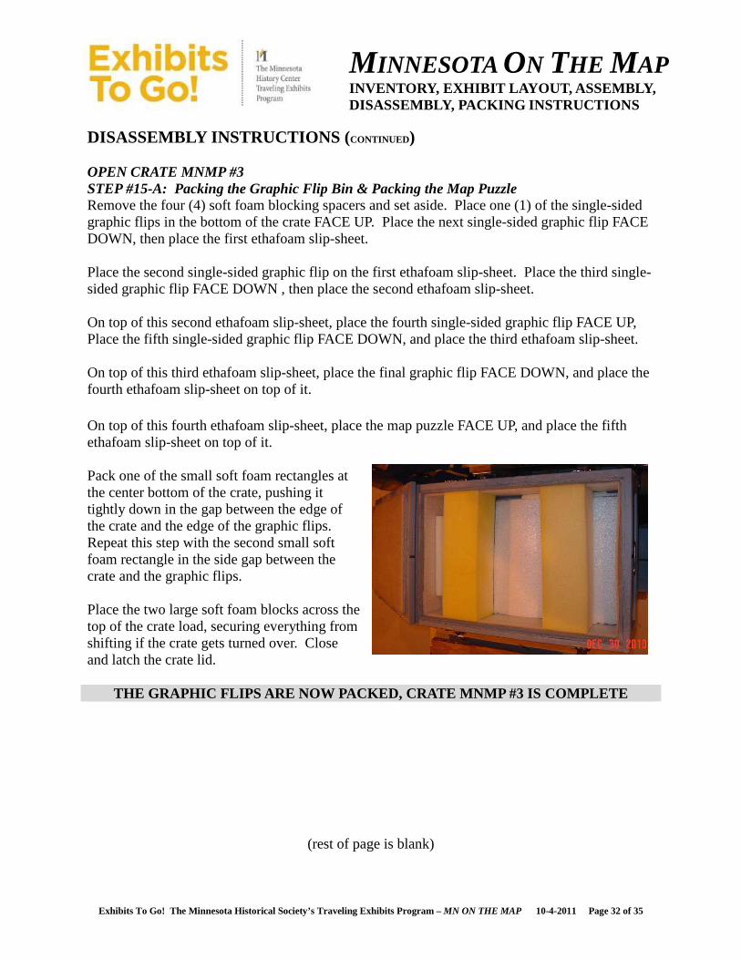
DISASSEMBLY INSTRUCTIONS ( CONTINUED) OPEN CRATE MNMP #3 STEP #15-A: Packing the Graphic Flip Bin & Packing the Map Puzzle Remove the four (4) soft foam blocking spacers and set aside. Place one (1) of the single-sided graphic flips in the bottom of the crate FACE UP. Place the next single-sided graphic flip FACE DOWN, then place the first ethafoam slip-sheet. Place the second single-sided graphic flip on the first ethafoam slip-sheet. Place the third single-sided graphic flip FACE DOWN , then place the second ethafoam slip-sheet. On top of this second ethafoam slip-sheet, place the fourth single-sided graphic flip FACE UP, Place the fifth single-sided graphic flip FACE DOWN, and place the third ethafoam slip-sheet. On top of this third ethafoam slip-sheet, place the final graphic flip FACE DOWN, and place the fourth ethafoam slip-sheet on top of it. On top of this fourth ethafoam slip-sheet, place the map puzzle FACE UP, and place the fifth ethafoam slip-sheet on top of it. Pack one of the small soft foam rectangles at the center bottom of the crate, pushing it tightly down in the gap between the edge of the crate and the edge of the graphic flips. Repeat this step with the second small soft foam rectangle in the side gap between the crate and the graphic flips. Place the two large soft foam blocks across the top of the crate load, securing everything from shifting if the crate gets turned over. Close and latch the crate lid.
THE GRAPHIC FLIPS ARE NOW PACKED, CRATE MNMP #3 IS COMPLETE
(rest of page is blank)
MINNESOTA ON THE MAP INVENTORY, EXHIBIT LAYOUT, ASSEMBLY, DISASSEMBLY, PACKING INSTRUCTIONS
Exhibits To Go! The Minnesota Historical Society’s Traveling Exhibits Program – MN ON THE MAP 10-4-2011 Page 33 of 35
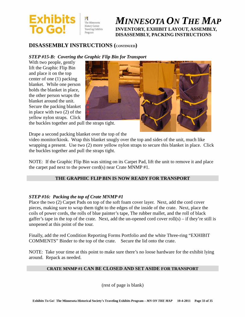
DISASSEMBLY INSTRUCTIONS ( CONTINUED) STEP #15-B: Covering the Graphic Flip Bin for Transport With two people, gently lift the Graphic Flip Bin and place it on the top center of one (1) packing blanket. While one person holds the blanket in place, the other person wraps the blanket around the unit. Secure the packing blanket in place with two (2) of the yellow nylon straps. Click the buckles together and pull the straps tight. Drape a second packing blanket over the top of the video monitor/kiosk. Wrap this blanket snugly over the top and sides of the unit, much like wrapping a present. Use two (2) more yellow nylon straps to secure this blanket in place. Click the buckles together and pull the straps tight. NOTE: If the Graphic Flip Bin was sitting on its Carpet Pad, lift the unit to remove it and place the carpet pad next to the power cord(s) near Crate MNMP #1.
THE GRAPHIC FLIP BIN IS NOW READY FOR TRANSPORT STEP #16: Packing the top of Crate MNMP #1 Place the two (2) Carpet Pads on top of the soft foam cover layer. Next, add the cord cover pieces, making sure to wrap them tight to the edges of the inside of the crate. Next, place the coils of power cords, the rolls of blue painter’s tape, The rubber mallet, and the roll of black gaffer’s tape in the top of the crate. Next, add the un-opened cord cover roll(s) – if they’re still is unopened at this point of the tour. Finally, add the red Condition Reporting Forms Portfolio and the white Three-ring “EXHIBIT COMMENTS” Binder to the top of the crate. Secure the lid onto the crate. NOTE: Take your time at this point to make sure there’s no loose hardware for the exhibit lying around. Repack as needed.
CRATE MNMP #1 CAN BE CLOSED AND SET ASIDE FOR TRANSPORT
(rest of page is blank)
MINNESOTA ON THE MAP INVENTORY, EXHIBIT LAYOUT, ASSEMBLY, DISASSEMBLY, PACKING INSTRUCTIONS
Exhibits To Go! The Minnesota Historical Society’s Traveling Exhibits Program – MN ON THE MAP 10-4-2011 Page 34 of 35
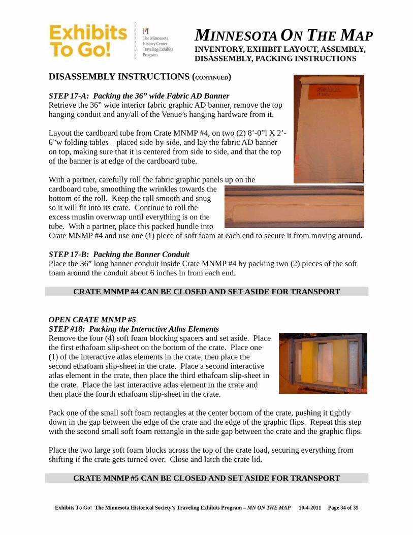
DISASSEMBLY INSTRUCTIONS ( CONTINUED) STEP 17-A: Packing the 36” wide Fabric AD Banner Retrieve the 36” wide interior fabric graphic AD banner, remove the top hanging conduit and any/all of the Venue’s hanging hardware from it. Layout the cardboard tube from Crate MNMP #4, on two (2) 8’-0”l X 2’-6”w folding tables – placed side-by-side, and lay the fabric AD banner on top, making sure that it is centered from side to side, and that the top of the banner is at edge of the cardboard tube. With a partner, carefully roll the fabric graphic panels up on the cardboard tube, smoothing the wrinkles towards the bottom of the roll. Keep the roll smooth and snug so it will fit into its crate. Continue to roll the excess muslin overwrap until everything is on the tube. With a partner, place this packed bundle into Crate MNMP #4 and use one (1) piece of soft foam at each end to secure it from moving around. STEP 17-B: Packing the Banner Conduit Place the 36” long banner conduit inside Crate MNMP #4 by packing two (2) pieces of the soft foam around the conduit about 6 inches in from each end.
CRATE MNMP #4 CAN BE CLOSED AND SET ASIDE FOR TRANSPORT OPEN CRATE MNMP #5 STEP #18: Packing the Interactive Atlas Elements Remove the four (4) soft foam blocking spacers and set aside. Place the first ethafoam slip-sheet on the bottom of the crate. Place one (1) of the interactive atlas elements in the crate, then place the second ethafoam slip-sheet in the crate. Place a second interactive atlas element in the crate, then place the third ethafoam slip-sheet in the crate. Place the last interactive atlas element in the crate and then place the fourth ethafoam slip-sheet in the crate. Pack one of the small soft foam rectangles at the center bottom of the crate, pushing it tightly down in the gap between the edge of the crate and the edge of the graphic flips. Repeat this step with the second small soft foam rectangle in the side gap between the crate and the graphic flips. Place the two large soft foam blocks across the top of the crate load, securing everything from shifting if the crate gets turned over. Close and latch the crate lid.
CRATE MNMP #5 CAN BE CLOSED AND SET ASIDE FOR TRANSPORT
MINNESOTA ON THE MAP INVENTORY, EXHIBIT LAYOUT, ASSEMBLY, DISASSEMBLY, PACKING INSTRUCTIONS
Exhibits To Go! The Minnesota Historical Society’s Traveling Exhibits Program – MN ON THE MAP 10-4-2011 Page 35 of 35
DISASSEMBLY INSTRUCTIONS ( CONTINUED) OPEN THE ACCESSORIES/TOOL BAG STEP #19: Packing the Accessories/Tool Bag Make sure everything has been put back into the Accessories/Tool Bag.
ACCESSORIES/TOOL BAG Cleaning kit (Plexi cleaner and wipes – box of wipes strapped to outside) 1 Tour Manual (three-ring binder) 1 Manual 16 Foot Tape Measure 1 Extra Zip-ties for Kiosk Power Cord(s) – small, black 1 bag of 100 Extra Zip-ties for Kiosk Power Cord(s) – medium, black 1 bag of 100 Side-cutter to remove Zip-ties 1 Extra Graphic Pocket Rod Moveable Mounting Screw Glides 1 bag of 6 Extra Set joiners, 90 degree 1 bag of 6 Extra Set joiners, multiple angles 1 bag of 8 Spacer Tool – for setting upper Moveable Mounting Screw Glides 1 Slip-joint Pliers to tighten upper Moveable Mounting Screw Glides 1 Plastic Accessory Box with Video Monitor/Kiosk Equipment, including:
1
• One (1) Flashlight • One (1) Key – to open Monitor • Many Small Black Zip-ties
• One (1) Multi-tipped Screwdriver • Two (2) Allen Wrenches
• Twelve (12) Allen-head Socket Screws NOTE: Take your time at this point to make sure there’s no loose hardware for the exhibit lying around. Repack as needed.
THE ACCESSORIES/TOOL BAG IS NOW COMPLETE AND READY FOR TRANSPORT
(rest of page is blank)