Embed Size (px)
Citation preview
24 October 2013 Motion Imagery Standards Board 1
RECOMMENDED PRACTICE
Metric Geopositioning Metadata Set
MISB RP 1107
24 October 2013
1 Scope
This Recommended Practice (RP) defines threshold and objective metadata elements for
photogrammetric applications. This RP defines a new Local Data Set (LDS) with metadata
elements selected from MISB RP 0801[1], MISB RP 1010[1], and MISB RP 1202[3]The
metadata elements specific to metric sensing are a subset of RP 0801 photogrammetric metadata
elements. This RP supersedes MISB EG 0810[10].
2 References
2.1 Normative Reference
The following references and the references contained therein are normative.
[1] MISB RP 0801.4 Photogrammetry Metadata Set for Digital Motion Imagery, Oct 2013
[2] MISB RP 1010 Generalized Standard Deviation and Correlation Coefficient Metadata, Oct
2013
[3] MISB RP 1202 Generalized Transformation Parameters, Oct 2013
[4] SMPTE RP 210v13:2012 Metadata Element Dictionary
[5] MISB ST 0807.12 MISB KLV Metadata Dictionary, Oct 2013
[6] MISB ST 0603.1 Common Time Reference for Digital Motion Imagery using Coordinated
Universal Time (UTC), Jun 2011
[7] MISB RP 0701 Common Metadata System: Structure, Aug 2007
[8] MISB ST 0107.1 Bit and Byte Order for Metadata in Motion Imagery Files and Streams,
Jun 2011
[9] MISB RP 1201 Floating Point to Integer Mapping, Feb 2012
2.2 Informative References
[10] MISB EG 0810.2 Profile 2: KLV for LVSD Applications
3 Abbreviations and Acronyms
CE Circular Error
CSM Community Sensor Model

MISB RP 1107 Metric Geopositioning Metadata Set
24 October 2013 Motion Imagery Standards Board 2
DGMS Direct Geopositioning Metric Sensor
EG Engineering Guideline
FFOV Full Field-of-View
FLP Floating Length Pack
KLV Key-Length-Value
LDS Local Data Sets
LE Linear Error
LRF Laser Range Finder
MISB Motion Imagery Standards Board
NITF National Imagery Transmission Format
PED Processing, Exploitation, and Dissemination
RP Recommended Practice
SACP Single Aimpoint Center Pixel
SET Sensor Exploitation Tool
SMPTE Society of Motion Picture and Television Engineers
ST Standard
TLE Target Location Error
TRE Tagged Reference Extension
4 Introduction
A metric sensor collects sufficient metadata to support the computation of a target coordinate
(latitude, longitude, and height-above-ellipsoid), and its uncertainty (TLE or CE/LE). A metric
sensor that enables the computation of the target coordinate(s) and uncertainties from a single
image is a Direct Geopositioning Metric Sensor (DGMS). A DGMS integrates a Laser Range
Finder (LRF) or a framing LIDAR sensor into the sensor system. The value of a DGMS is the
ability to generate target coordinates (latitude, longitude, and elevation) and an error estimate
(TLE or CE/LE) for those coordinates with a known level of confidence as a result of direct
calculation.
Two critical elements are required to exploit a metric sensor and a DGMS: (1) a rigorous sensor
model; and (2) a complete set of metadata describing the sensor state and the measurement
uncertainties of that state. These elements enable a myriad of down-stream Processing,
Exploitation, and Dissemination (PED), such as allowing imagery to be combined with other
imagery or data sources (i.e. data fusion). The sensor model is managed by the
GWG/Community Sensor Model Working Group; however, the metadata elements to describe
the sensor state and the measurement uncertainties is the intent of this RP.
Integrating metric capability with motion imagery is increasingly important as motion imagery
plays a more significant role in fulfilling ISR mission needs. The photogrammetric metadata
defined in MISB RP 0801[1] provides all of the required elements to describe a sensor with
sufficient content to compute precision geolocations. The variance-covariance information about
the parameters in RP 0801 may be conveyed through MISB RP 1010[1]. The first 31 elements of
the LDS defined in this RP are the elements in RP 0801 that have uncertainty information
(consistent with the order required in RP 1010). The Standard Deviation and Correlation FLP per
RP 1010 for these elements immediately follows. The remaining elements of the LDS lists
elements in RP 0801 that do not have an uncertainty model.

MISB RP 1107 Metric Geopositioning Metadata Set
24 October 2013 Motion Imagery Standards Board 3
5 Revisions
Revision Date Summary of Changes Original Draft 10/31/2011 Original Draft of RP 1107 for review and comment
09/30/2013 Expanded support of Standard Deviation Correlation Coefficient Floating Length Pack
6 Accuracy and Metricity
The terms “accuracy” and “metricity” have two different but related definitions. Accuracy is a
measure of how well a system is able to calculate the location of a point of interest compared to
its actual location in the real world. A more accurate sensor can produce target coordinates closer
to the true location of a coordinate (i.e. the missed distance is small) than a less accurate sensor.
Accuracy is usually stated as a system requirement, and is dependent on how well a system
measures its state when an image is collected. A system may improve its accuracy by using
higher quality system components (e.g. improved IMU or GPS solution). Understanding the
accuracy of a sensor’s metadata requires the measurement uncertainties (errors); this refers to the
metricity.
Metricity provides confidence in the calculated location of a point of interest. This confidence is
expressed in terms of predicted uncertainties for various components of the geopositioning
result, and therefore, is dependent on how well the system knows the uncertainties (errors)
associated with the measured system parameters for each image. A metric sensor reports the
metadata elements as dynamic information available about the system at the time the imagery is
captured by the system. Even when values have large uncertainties and inaccurate data, the
sensor is metric. On the other hand, a system that does not provide current error estimates for
dynamic system values may not be considered metric.
Figure 1 illustrates this relationship between accuracy and metricity. The lower left quadrant
represents a less accurate, non-metric system. The calculated target location shows a large
displacement when compared to the actual geolocation of the target. By improving the system
components, the system may become more accurate and move into the lower right quadrant. For
both of these non-metric cases, the confidence in the calculated target location is unknown.
If, however, the less accurate, non-metric system of the lower left quadrant provided error
estimates for the dynamic system parameters, it becomes a metric sensor and moves to the upper
left quadrant. While such a system may not improve in accuracy, the confidence in the calculated
target location is known and may be used for engagement, collateral damage assessment,
weapons effect calculations or other precision based tasks. The ideal case is where the system
components are of sufficient high quality for accuracy and produce error estimates for the
dynamic system parameters. This is the case shown in the upper right quadrant, and such a
system is able to provide actionable target information.

MISB RP 1107 Metric Geopositioning Metadata Set
24 October 2013 Motion Imagery Standards Board 4
Figure 1: Relationship between accuracy and metricity
7 Metadata Timing
Metric sensors require more than just populated system parameters and error estimates. The
system timing architecture must be understood and accounted for in the system design. The LDS
includes a metadata element to record the time for when the set of metadata elements are valid.
Uncertainties and misalignments in the timing architecture can cause large increases in the
uncertainty of calculated target coordinates. It is recommended that systems implementing this
RP have the capability to capture and time tag the metadata at the same time the corresponding
image is captured. Any timing differences between the metadata elements themselves, or
between the metadata elements and the image capture must be understood and accounted for in
the uncertainty (error) estimates.
8 Bandwidth Considerations
RP 1107 LDS offers a significant reduction in the amount of information transmitted as
compared to the Truncation Packs endorsed by version 3 or prior of RP 0801. This efficiency is
realized for several reasons: (1) combining metadata elements from various ST/RP/EG’s into a
single LDS replaces the 16-byte UL key required for each element to be represented by a one-
byte tag; (2) the variance-covariance information is contained in one location (the RP 1010 tag),
eliminating the need for that information in the RP 0801 Truncation Packs; and (3) a single time
tag is recorded in the LDS for all data elements, eliminating the need for time in the RP 0801
Truncation Packs.

MISB RP 1107 Metric Geopositioning Metadata Set
24 October 2013 Motion Imagery Standards Board 5
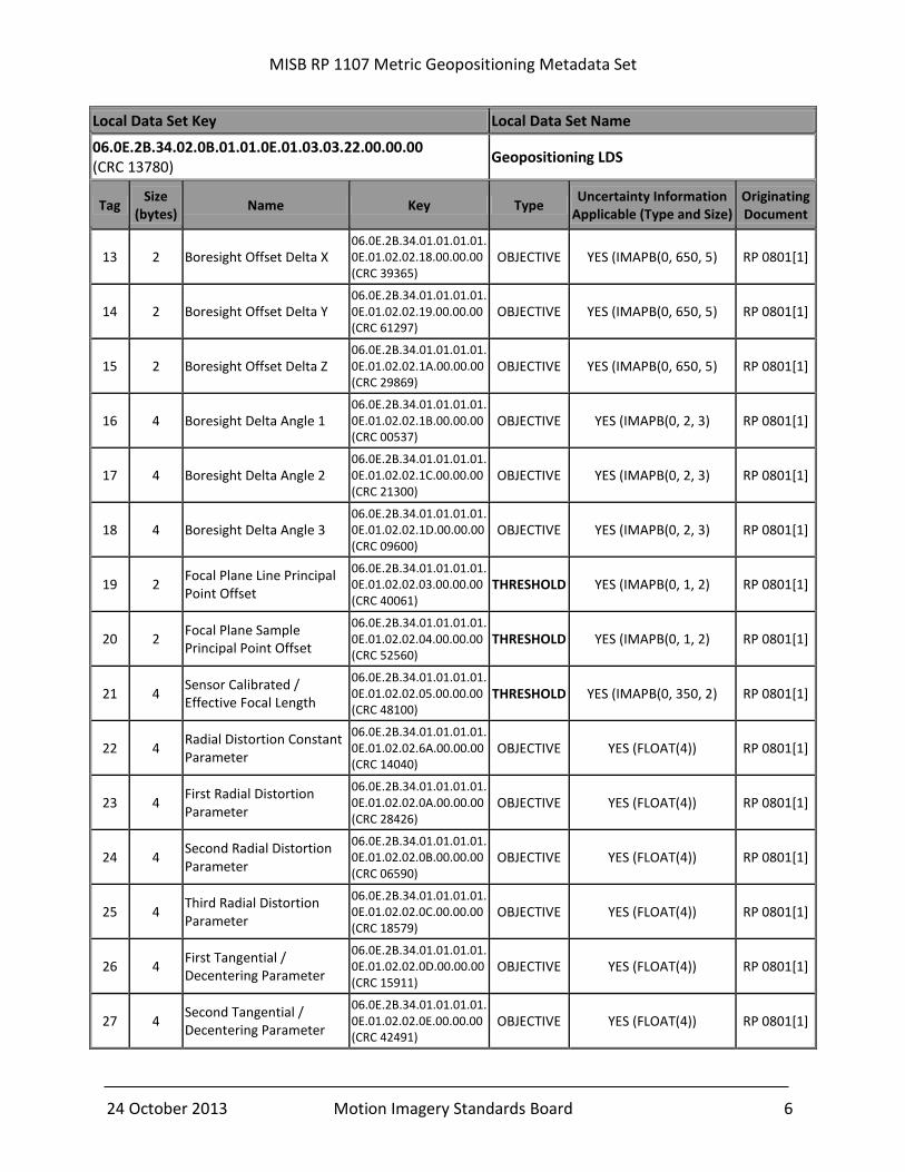
9 Metric Geopositioning Local Data Set (LDS)
The Local Data Set for Metric sensors is listed in Table 1. The documents from which these
metadata elements are defined contain more detail regarding the data type, size, and integer
mapping, if applicable. “Type” indicates a priority of element, where Threshold elements are
mandatory, and Objective elements are desired.
Table 1: Metric Geopositioning Local Data Set (LDS)
Local Data Set Key Local Data Set Name
06.0E.2B.34.02.0B.01.01.0E.01.03.03.22.00.00.00 (CRC 13780)
Geopositioning LDS
Tag Size
(bytes) Name Key Type
Uncertainty Information Applicable (Type and Size)
Originating Document
1 5 Sensor ECEF Position Component X
06.0E.2B.34.01.01.01.01.0E.01.02.01.25.00.00.00 (CRC 25208)
THRESHOLD YES (IMAPB(0, 650, 2) RP 0801[1]
2 5 Sensor ECEF Position Component Y
06.0E.2B.34.01.01.01.01.0E.01.02.01.26.00.00.00 (CRC 63908)
THRESHOLD YES (IMAPB(0, 650, 2) RP 0801[1]
3 5 Sensor ECEF Position Component Z
06.0E.2B.34.01.01.01.01.0E.01.02.01.27.00.00.00 (CRC 36624)
THRESHOLD YES (IMAPB(0, 650, 2) RP 0801[1]
4 3 Sensor ECEF Velocity Component X
06.0E.2B.34.01.01.01.01.0E.01.02.01.2E.00.00.00 (CRC 31847)
OBJECTIVE YES (IMAPB(-900, 900, 2) RP 0801[1]
5 3 Sensor ECEF Velocity Component Y
06.0E.2B.34.01.01.01.01.0E.01.02.01.2F.00.00.00 (CRC 2771)
OBJECTIVE YES (IMAPB(-900, 900, 2) RP 0801[1]
6 3 Sensor ECEF Velocity Component Z
06.0E.2B.34.01.01.01.01.0E.01.02.01.30.00.00.00 (CRC 50586)
OBJECTIVE YES (IMAPB(-900, 900, 2) RP 0801[1]
7 4 Sensor Absolute Heading 06.0E.2B.34.01.01.01.01.0E.01.02.01.37.00.00.00 (CRC 38071)
THRESHOLD YES (IMAPB(0, 0.2, 2) RP 0801[1]
8 4 Sensor Absolute Pitch 06.0E.2B.34.01.01.01.01.0E.01.02.01.38.00.00.00 (CRC 16473)
THRESHOLD YES (IMAPB(0, 0.2, 2) RP 0801[1]
9 4 Sensor Absolute Roll 06.0E.2B.34.01.01.01.01.0E.01.02.01.39.00.00.00 (CRC 14061)
THRESHOLD YES (IMAPB(0, 0.2, 2) RP 0801[1]
10 2 Sensor Absolute Heading Rate
06.0E.2B.34.01.01.01.01.0E.01.02.01.40.00.00.00 (CRC 34799)
OBJECTIVE YES (IMAPB(0, 70, 2) RP 0801[1]
11 2 Sensor Absolute Pitch Rate 06.0E.2B.34.01.01.01.01.0E.01.02.01.41.00.00.00 (CRC 61787)
OBJECTIVE YES (IMAPB(0, 70, 2) RP 0801[1]
12 2 Sensor Absolute Roll Rate 06.0E.2B.34.01.01.01.01.0E.01.02.01.42.00.00.00 (CRC 27271)
OBJECTIVE YES (IMAPB(0, 70, 2) RP 0801[1]
MISB RP 1107 Metric Geopositioning Metadata Set
24 October 2013 Motion Imagery Standards Board 6
Local Data Set Key Local Data Set Name
06.0E.2B.34.02.0B.01.01.0E.01.03.03.22.00.00.00 (CRC 13780)
Geopositioning LDS
Tag Size
(bytes) Name Key Type
Uncertainty Information Applicable (Type and Size)
Originating Document
13 2 Boresight Offset Delta X 06.0E.2B.34.01.01.01.01.0E.01.02.02.18.00.00.00 (CRC 39365)
OBJECTIVE YES (IMAPB(0, 650, 5) RP 0801[1]
14 2 Boresight Offset Delta Y 06.0E.2B.34.01.01.01.01.0E.01.02.02.19.00.00.00 (CRC 61297)
OBJECTIVE YES (IMAPB(0, 650, 5) RP 0801[1]
15 2 Boresight Offset Delta Z 06.0E.2B.34.01.01.01.01.0E.01.02.02.1A.00.00.00 (CRC 29869)
OBJECTIVE YES (IMAPB(0, 650, 5) RP 0801[1]
16 4 Boresight Delta Angle 1 06.0E.2B.34.01.01.01.01.0E.01.02.02.1B.00.00.00 (CRC 00537)
OBJECTIVE YES (IMAPB(0, 2, 3) RP 0801[1]
17 4 Boresight Delta Angle 2 06.0E.2B.34.01.01.01.01.0E.01.02.02.1C.00.00.00 (CRC 21300)
OBJECTIVE YES (IMAPB(0, 2, 3) RP 0801[1]
18 4 Boresight Delta Angle 3 06.0E.2B.34.01.01.01.01.0E.01.02.02.1D.00.00.00 (CRC 09600)
OBJECTIVE YES (IMAPB(0, 2, 3) RP 0801[1]
19 2 Focal Plane Line Principal Point Offset
06.0E.2B.34.01.01.01.01.0E.01.02.02.03.00.00.00 (CRC 40061)
THRESHOLD YES (IMAPB(0, 1, 2) RP 0801[1]
20 2 Focal Plane Sample Principal Point Offset
06.0E.2B.34.01.01.01.01.0E.01.02.02.04.00.00.00 (CRC 52560)
THRESHOLD YES (IMAPB(0, 1, 2) RP 0801[1]
21 4 Sensor Calibrated / Effective Focal Length
06.0E.2B.34.01.01.01.01.0E.01.02.02.05.00.00.00 (CRC 48100)
THRESHOLD YES (IMAPB(0, 350, 2) RP 0801[1]
22 4 Radial Distortion Constant Parameter
06.0E.2B.34.01.01.01.01.0E.01.02.02.6A.00.00.00 (CRC 14040)
OBJECTIVE YES (FLOAT(4)) RP 0801[1]
23 4 First Radial Distortion Parameter
06.0E.2B.34.01.01.01.01.0E.01.02.02.0A.00.00.00 (CRC 28426)
OBJECTIVE YES (FLOAT(4)) RP 0801[1]
24 4 Second Radial Distortion Parameter
06.0E.2B.34.01.01.01.01.0E.01.02.02.0B.00.00.00 (CRC 06590)
OBJECTIVE YES (FLOAT(4)) RP 0801[1]
25 4 Third Radial Distortion Parameter
06.0E.2B.34.01.01.01.01.0E.01.02.02.0C.00.00.00 (CRC 18579)
OBJECTIVE YES (FLOAT(4)) RP 0801[1]
26 4 First Tangential / Decentering Parameter
06.0E.2B.34.01.01.01.01.0E.01.02.02.0D.00.00.00 (CRC 15911)
OBJECTIVE YES (FLOAT(4)) RP 0801[1]
27 4 Second Tangential / Decentering Parameter
06.0E.2B.34.01.01.01.01.0E.01.02.02.0E.00.00.00 (CRC 42491)
OBJECTIVE YES (FLOAT(4)) RP 0801[1]

MISB RP 1107 Metric Geopositioning Metadata Set
24 October 2013 Motion Imagery Standards Board 7
Local Data Set Key Local Data Set Name
06.0E.2B.34.02.0B.01.01.0E.01.03.03.22.00.00.00 (CRC 13780)
Geopositioning LDS
Tag Size
(bytes) Name Key Type
Uncertainty Information Applicable (Type and Size)
Originating Document
28 4 Third Tangential / Decentering Parameter
06.0E.2B.34.01.01.01.01.0E.01.02.02.83.00.00.00 (CRC 16709)
OBJECTIVE YES (FLOAT(4)) RP 0801[1]
29 4 Differential Scale Affine Parameter
06.0E.2B.34.01.01.01.01.0E.01.02.02.0F.00.00.00 (CRC 54095)
OBJECTIVE YES (FLOAT(4)) RP 0801[1]
30 4 Skewness Affine Parameter
06.0E.2B.34.01.01.01.01.0E.01.02.02.10.00.00.00 (CRC 07174)
OBJECTIVE YES (FLOAT(4)) RP 0801[1]
31 4 Slant Range 06.0E.2B.34.01.01.01.01.07.01.08.01.01.00.00.00 (CRC 16588)
OBJECTIVE YES (IMAPB(0, 650, 2) SMPTE RP
210[4]
32 V Standard Deviation and Correlation Coefficient FLP
06.0E.2B.34.02.05.01.01.0E.01.03.03.21.00.00.00 (CRC 64882)
THRESHOLD N/A RP 1010[1]
33 V Generalized Transformation LDS
06.0E.2B.34.02.0B.01.01.0E.01.03.05.05.00.00.00 (CRC 40498)
OBJECTIVE YES (Variable) RP 1202[3]
34 2 Image Rows 06.0E.2B.34.01.01.01.01.0E.01.02.02.06.00.00.00 (CRC 08248)
THRESHOLD NO RP 0801[1]
35 2 Image Columns 06.0E.2B.34.01.01.01.01.0E.01.02.02.07.00.00.00 (CRC 22156)
THRESHOLD NO RP 0801[1]
36 2 Pixel Size X 06.0E.2B.34.01.01.01.01.0E.01.02.02.82.00.00.00 (CRC 14321)
THRESHOLD NO RP 0801[1]
37 2 Pixel Size Y 06.0E.2B.34.01.01.01.01.0E.01.02.02.82.01.00.00 (CRC 00193)
THRESHOLD NO RP 0801[1]
38 1 Slant Range Pedigree 06.0E.2B.34.01.01.01.01.0E.01.02.02.87.00.00.00 (CRC 35764)
OBJECTIVE NO RP 0801[1]
39 4 Measured Line Coordinate for Range
06.0E.2B.34.01.01.01.01.0E.01.02.05.07.00.00.00 (CRC 12632)
OBJECTIVE NO RP 0801[1]
40 4 Measured Sample Coordinate for Range
06.0E.2B.34.01.01.01.01.0E.01.02.05.08.00.00.00 (CRC 58806)
OBJECTIVE NO RP 0801[1]
41 4 LRF Divergence 06.0E.2B.34.01.01.01.01.0E.01.02.05.09.00.00.00 (CRC 37634)
OBJECTIVE NO RP 0801[1]
42 4 Valid Range of Radial Distortion
06.0E.2B.34.01.01.01.01.0E.01.02.02.69.00.00.00 (CRC 44292)
OBJECTIVE NO RP 0801[1]

MISB RP 1107 Metric Geopositioning Metadata Set
24 October 2013 Motion Imagery Standards Board 8
Local Data Set Key Local Data Set Name
06.0E.2B.34.02.0B.01.01.0E.01.03.03.22.00.00.00 (CRC 13780)
Geopositioning LDS
Tag Size
(bytes) Name Key Type
Uncertainty Information Applicable (Type and Size)
Originating Document
43 8 POSIX Microseconds (Precision Time Stamp)
06.0E.2B.34.01.01.01.03.07.02.01.01.01.05.00.00 (CRC 64827)
THRESHOLD NO ST 0603[6]
44 1 Document Version 06.0E.2B.34.01.01.01.01 0E.01.02.05.05.00.00.00 (CRC 56368)
THRESHOLD NO ST 0807[5]
45 2 CRC-16-CCITT 06.0E.2B.34.01.01.01.01.0E.01 02.03.5E.00.00 00 (CRC 31377)
THRESHOLD NO RP 0701[7]
10 Metadata Requirements
Requirement
RP 1107-01 All metadata shall be expressed in accordance with MISB ST 0107[8].
RP 1107-02 All metadata elements indicated as THRESHOLD in MISB RP 1107 Table 1 shall be populated and transmitted in the Metric Geopositioning LDS.
To help detect erroneous metadata after transmission, a 2-byte CRC is included in every LDS as
the last item. The CRC is computed across the entire LDS packet starting with the 16-byte LDS
key and ending with the length field of the CRC data element. Figure 2 illustrates the data range
the checksum is performed over. If the calculated CRC of the received LDS packet does not
match the CRC stored in the packet, the packet is discarded as being invalid.
Figure 2: CRC Representation
The “Threshold” elements represent the core elements required for Single Aim Center Pixel
(SACP) DGMS exploitation. The additional “Objective” elements complete an ideal set of
elements for a DGMS that may yield results with the highest fidelity. The Objective elements are
also required for Full Field of View (FFOV) exploitation.
The column labeled “Uncertainty Information Applicable” further denotes whether Standard
Deviation and Correlation Coefficient metricity information is applicable. Elements labeled with
“YES” have Standard Deviation and Correlation Coefficient information that may be applied;
LDS Key16-byte Key
BER Length
ValueT | L | V
TimestampT | L | V
MetadataT | L | V
MetadataT | L | CRC
CRC is Computed from the start of the 16 byte key through the Length Value of the CRC tag

MISB RP 1107 Metric Geopositioning Metadata Set
24 October 2013 Motion Imagery Standards Board 9
these elements are followed by the recommended data type and size in parentheses. The elements
labeled “No” do not require Standard Deviation and Correlation Coefficient information.
The last column identifies the originating document where the individual element is defined,
which provides a more detailed description of the data element.
Requirement
RP 1107-03 The program office shall select from the “Objective” elements in MISB RP 1107 Table 1 to produce a data population plan that enables the full capability for their system.
RP 1107-04 When transmitting a Metric Geopositioning LDS either the airborne platform elements or the spaceborne platform elements shall be used, but not both.
RP 1107-05 When the Metric Geopositioning LDS is used for airborne DGMS application, real-time position ECEF values as represented by LDS Tags 1, 2 and 3 shall be present.
RP 1107-06 When the Metric Geopositioning LDS is used for spaceborne DGMS application, real-time ECEF values as represented by LDS Tags 7, 8 and 9 shall be present.
RP 1107-07 Only one value of position information shall be transmitted in the stream.
RP 1107-08 Position information shall be transmitted only once per stream.
RP 1107-09 Only one value of velocity information shall be transmitted in the stream.
RP 1107-10 Velocity information shall be transmitted only once per stream.
RP 1107-11 Standard Deviation and Correlation Coefficient metricity information of a data element shall be conveyed in accordance with MISB RP 1010[1].
11 Invoking MISB RP 1010
For a detailed description of how to invoke RP 1010 for conveying Standard Deviation and
Correlation Coefficient uncertainty information, please consult MISB RP 1010[1]. The five
elements required to invoke RP 1010 are listed below.
11.1 Matrix Size N
The first element is the matrix size N that describes uncertainty information for N corresponding
elements in Table 1. A given value of N indicates that Standard Deviation and Correlation
Coefficient uncertainty information, corresponding to a selected N elements in Table 1, is
provided in a Standard Deviation and Correlation Coefficient FLP.
The index of Standard Deviation is associated with its corresponding Tag Number in Table 1.
The Correlation Coefficient index is represented by the combination of two non-equal Tag
Numbers in Table 1.
11.2 Parse Control Byte
The second element is the Parse Control Byte, which indicates whether the correlation values are
sparsely represented, and also provides the number of bytes used for both the standard deviation
(sigma) and correlation (rho) values. The recommended data type and size is listed in

MISB RP 1107 Metric Geopositioning Metadata Set
24 October 2013 Motion Imagery Standards Board 10
parentheses after the “YES” for all applicable elements in the Uncertainty Information
Applicable column in Table 1. Rho values are mapped integers using IMAPB(-1.0,1.0,CLength)
(see MISB RP 1201[9]). The recommended value for CLength is two (2) bytes for all correlation
coefficients related to the parameters in Table 1, although this does not limit the use of additional
bytes if a system requires greater precision.
11.3 Bit Vector
The third element in the Standard Deviation and Correlation FPL is a Bit Vector mask, where a
“1” indicates that a value is present and a “0” that a value is not.
11.4 Standard Deviation and Correlation Coefficient Values
The final two elements in the Standard Deviation and Correlation FPL are the standard deviation
elements and correlation coefficient elements respectively, first sorted by row index and second
by column index.
Only the upper triangle elements on the Standard Deviation and Correlation Coefficient matrix
are used when invoking RP 1010. Please refer to MISB RP 1010 for further description of the
five elements contained in the Standard Deviation and Correlation Coefficient FLP.
12 Image Coordinate Frame
The definition of the image coordinate system is critical in these Standards. The focus of this
metadata is to support a Community Sensor Model (CSM) compliant sensor models for
geopositioning activities. The CSM Technical Requirements Document (TRD) has a defined
image coordinate system used in all of the computations.
The default transformation from the pixel-space (shown in Figure 3) to the “virtual” image-space
coordinate system is shown in Figure 4.
Figure 3: Pixel Coordinate System per
CSM TRD
Figure 4: Virtual Image Coordinate System

MISB RP 1107 Metric Geopositioning Metadata Set
24 October 2013 Motion Imagery Standards Board 11
If the image requires the default transformation and additional transformations to relate the pixel-
space to the “virtual” image-space, then use of MISB RP 1202 is required. RP 1202 provides
additional transformations to define the relationship between the pixel-space and the “virtual”
image space. The full definition of these additional transformations is given in RP 1202.
13 Appendix - Informative
13.1 Parameter Information – RP 0801
MISB RP 0801 defines metadata elements that supports metric geo-location for a single sensor.
A complete description of the parameters is provided in RP 0801 and should be consulted for
reference. The following subsections provide a brief description of the parameters and
justification for classification as “Threshold” or “Objective” elements in Table 1.
13.1.1 Sensor Position
The sensor position is captured in Tag 1 through Tag 3. These tags are mandatory. Uncertainties
(sigmas) and correlation coefficients (rhos) are placed into the Standard Deviation and
Correlation Coefficient FLP. These establish sensor position for each image. Further description
of the sensor position parameters are contained in RP 0801.
13.1.2 Sensor Velocity
The external sensor velocity is captured in Tag 4 through Tag 6.These tags are optional. If
implemented, they represent real-time sensor ECEF velocity values. Uncertainties (sigmas) and
correlation coefficients (rhos) are placed into the Standard Deviation and Correlation Coefficient
FLP. These establish sensor velocity for each image. Further description of the sensor velocity
parameters are contained in RP 0801.
13.1.3 Sensor Orientation
The sensor orientation is captured in Tag 7 through Tag 9. Uncertainties (sigmas) and correlation
coefficients (rhos) are placed into the Standard Deviation and Correlation Coefficient FLP. The
correlation coefficients (rhos) are optional but should be provided if known. These establish
sensor pointing attitude for each image. Further description of the sensor orientation parameters
are contained in RP 0801.
13.1.4 Sensor Orientation Rate
The external sensor orientation rate is captured in Tag 10 through Tag 12. These Tags are
optional. If implemented, they represent real time sensor ECEF velocity values. Uncertainties
(sigmas) and correlation coefficients (rhos) are placed into the Standard Deviation and
Correlation Coefficient FLP. These establish sensor attitude rates for each image. Further
description of the sensor orientation rate parameters are contained in RP 0801.
MISB RP 1107 Metric Geopositioning Metadata Set
24 October 2013 Motion Imagery Standards Board 12
13.1.5 Boresight
The six elements of the boresighting information, Tag 13 through Tag 18, are optional for the
DGMS sensor data. Further description of this information is given in RP 0801. Uncertainties
(sigmas) and correlation coefficients (rhos) are placed into the Standard Deviation and
Correlation Coefficient FLP. Further description of the boresight parameters are contained in RP
0801.
13.1.6 Focal Plane
The focal plane is captured in Tag 19 through Tag 21. These tags are mandatory. The system
contains principal point offset values and the effective focal length of the sensor. Uncertainties
(sigmas) and correlation coefficients (rhos) are placed into the Standard Deviation and
Correlation Coefficient FLP. This information establishes the principal point offset for each
image. Further description of the focal plane parameters are contained in RP 0801.
13.1.7 Radial Distortion
The Internal Parameters Radial Distortion tags are optional. If used, this information is captured
in Tag 22 through Tag 25 and Tag 42. Further description of these parameters is found in RP
0801. Uncertainties (sigmas) and correlation coefficients (rhos) are placed into the Standard
Deviation and Correlation Coefficient FLP. Further description of the radial distortion
parameters are contained in RP 0801.
13.1.8 Tangential Decentering
The Internal Tangential/Decentering tags are optional. This system contains the
tangential/decentering distortion parameters values in Tag 26 through Tag 28. Further
description of these parameters is found in RP 0801. Uncertainties (sigmas) and correlation
coefficients (rhos) are placed into the Standard Deviation and Correlation Coefficient FLP.
Further descriptions of the tangential decentering parameters are contained in RP 0801.
13.1.9 Affine
The Internal Parameters Affine Correction tags are optional. This information is captured in Tag
29 and Tag 30. Further description of these parameters is found in RP 0801. Uncertainties
(sigmas) and correlation coefficients (rhos) are placed into the Standard Deviation and
Correlation Coefficient FLP. Further descriptions of the affine parameters are contained in RP
0801.
13.1.10 Slant Range
The Slant Range is optional; however, any system capable of measuring slant range should
provide slant range and slant range error in order to be metric. If used, Slant Range is captured in
Tag 31. Slant Range is defined in SMPTE RP 210[4] as, “The distance from the sensor to the
center point on the ground of the framed subject (image) depicted in the captured essence,
(default meters).” Use of the RP 0801 Slant Range has a range pedigree, Tag 38, that describes
if the slant range is a physically measured range (such as via laser range finder) or computed

MISB RP 1107 Metric Geopositioning Metadata Set
24 October 2013 Motion Imagery Standards Board 13
through inference or intersection with an elevation model. Also accompanied by the use of the
RP 0801 Slant Range is the measured line and sample for the Slant Range, Tag 39 and 40, and a
Laser Range Finder (LRF) Divergence value, Tag 41. The corresponding uncertainty (sigma) and
correlation coefficients (rhos) are placed into the Standard Deviation and Correlation Coefficient
FLP. Further description of the slant range parameters are contained in RP 0801.
13.1.11 Standard Deviation and Correlation Coefficient FLP
The standard deviation and correlation coefficient information is captured in the mandatory Tag
32. Please refer to MISB RP 1010[2] for further description of the Standard Deviation and
Correlation Coefficient FLP.
Two instances of the standard deviation and correlation coefficient information may exist within
this Local Data Set: (1) one instance for the RP 0801 data; and (2) one instance for the
Generalized Transformation LDS. Each instance contains an enumerated value that describes
which group of data elements it represents; therefore, each instance is self-describing and
uncorrelated to the other instances.
13.1.12 Generalized Transformation LDS
The Generalized Transformation Local Data Set is an optional set of data captured in Tag 33
used to relate the virtual image coordinate system to the distorted image coordinate system. The
Generalized Transformation LDS may appear up to four times in the Metric Geopositioning LDS
to account for all the enumerations defined in RP 1202. The full definition of the Generalized
Transformation LDS is given in RP 1202.
13.1.13 Image Size
The image size is captured in Tag 34 through Tag 37. These mandatory tags contain the number
of image rows and image columns and the x and y pixel size on the actively illuminated FPA.
These establish image size for each image. Further description of the image size parameters are
contained in RP 0801.