Embed Size (px)
Citation preview

Proactive Maintenance “Get To Know the Patient!”
Presented by: Rory S. McLaren
1

Proactive Maintenance Hydraulic systems are the only complex systems in which the total design is vested in one, or possibly two, disciplines, and they are both engineering.
It is apparent that the main focus of hydraulic system design is mechanical and/or electrical/electronic functionality.
2

Proactive Maintenance
Mechanical and electrical/electronic engineers are not trained in safety and maintenance as it applies to a hydraulic system. The problem is exacerbated by the fact that, in most cases, neither have operated a hydraulic machine, or performed service, maintenance, repair, or troubleshooting on a hydraulic system. In fact, most have apparently not performed prototype testing of the systems they design. Safety and proactive maintenance don’t just happen, they have to be vigorously pursued.
3
Proactive Maintenance
To design a safe and reliable hydraulic system requires three areas of expertise: • Mechanical and electrical/electronic engineering • Safety engineer • Reliability and maintenance engineer
4
Proactive Maintenance
My presentation is going to focus on two key areas: • How to “engineer” a hydraulic system from the point of view of maintenance. • How to perform proactive maintenance on a hydraulic system.
5

Proactive Maintenance
6

Proactive Maintenance 1. Focus: Oil level in reservoir Monitor interval: Before (or during) each shift (shift = 8-hours) Status: Critical
7
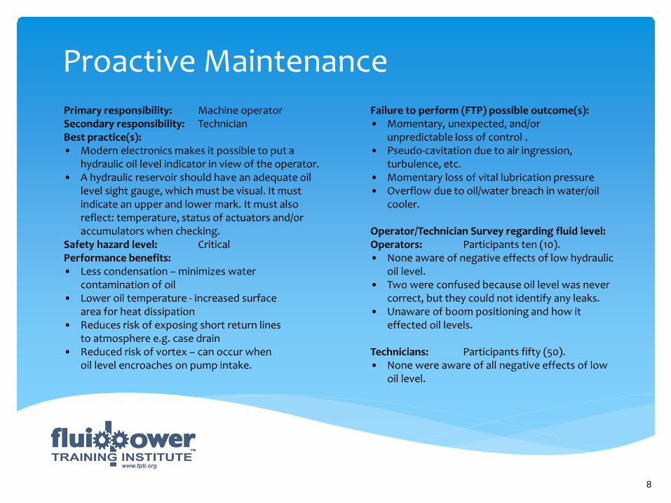
Proactive Maintenance Primary responsibility: Machine operator Secondary responsibility: Technician Best practice(s): • Modern electronics makes it possible to put a hydraulic oil level indicator in view of the operator. • A hydraulic reservoir should have an adequate oil level sight gauge, which must be visual. It must indicate an upper and lower mark. It must also reflect: temperature, status of actuators and/or accumulators when checking. Safety hazard level: Critical Performance benefits: • Less condensation – minimizes water contamination of oil • Lower oil temperature - increased surface area for heat dissipation • Reduces risk of exposing short return lines to atmosphere e.g. case drain • Reduced risk of vortex – can occur when oil level encroaches on pump intake.
Failure to perform (FTP) possible outcome(s): • Momentary, unexpected, and/or unpredictable loss of control . • Pseudo-cavitation due to air ingression, turbulence, etc. • Momentary loss of vital lubrication pressure • Overflow due to oil/water breach in water/oil cooler. Operator/Technician Survey regarding fluid level: Operators: Participants ten (10). • None aware of negative effects of low hydraulic oil level. • Two were confused because oil level was never correct, but they could not identify any leaks. • Unaware of boom positioning and how it effected oil levels. Technicians: Participants fifty (50). • None were aware of all negative effects of low oil level.
8
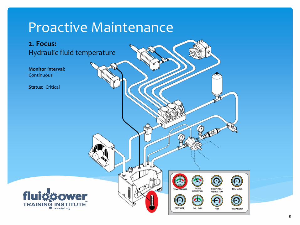
Proactive Maintenance 2. Focus: Hydraulic fluid temperature Monitor interval: Continuous Status: Critical
9

Proactive Maintenance Primary responsibility: Machine operator Secondary responsibility: Technician Best practice(s): • Fluid power designers must break with tradition and put oil temperature gauge in operator’s view. • Gauges should indicate correct, marginal and critical temperature levels. • Operators and technicians MUST receive training in cause and effect of excessive hydraulic fluid temperature. • Operator’s and technicians MUST know what action to take when oil fluid temperature reaches critical levels. Safety hazard level: Critical Optimum operating hydraulic fluid temperature: 130ºF (54ºC) Performance benefits: • Safety • Reliability • Increased component life • Optimize oil life • Optimize seal life
Failure to perform (FTP) possible outcome(s): • Unsafe system • Unpredictable • Substantially decreased oil life • Substantially decreased seal life Operator/Technician Survey regarding hydraulic fluid temperature: Operators: Participants ten (10). • None had means to observe temperature. • None were aware of cause and effect of high fluid temperature • None were aware of correct operating temperature for hydraulic fluid Technicians: Participants fifty (50). • None were aware of correct operating temperature of hydraulic fluid • Ten (10) reported observing hydraulic fluid operating in excess of 200ºF (93°C). • None were aware of negative effects of excessive hydraulic fluid temperature.
10

Proactive Maintenance 3. Focus: System operating pressure Monitor interval: Continuous Status: Critical
11

Proactive Maintenance Primary responsibility: Machine operator Secondary responsibility: Technician Best practice(s): • Fluid power designers must break with tradition and put oil pressure gauge (s) in operator’s view. • Gauges should indicate correct, marginal and critical oil pressure levels. • Operators and technicians MUST receive training in what pressure is, and purpose in the proper operation of a hydraulic system. • Operator’s and technicians MUST know what action to take when pressure is higher or lower than normal. Safety hazard level: Critical Optimum operating hydraulic fluid pressure: Hydraulic system dependent Performance benefits: • Safety • Reliability • Increased component life • Optimized machine performance
Failure to perform (FTP) possible outcome(s): • Unsafe system • Unpredictable Operator/Technician Survey regarding system operating pressure: Operators: Participants ten (10). • Could explain where pressure comes from – 0% • Could explain correct operating pressure(s) – 0% • Could observe operating pressure while operating system – 0% • Could explain hazards associated with operating at excessive pressure – 0% • Received training in pressure – 0% Technicians: Participants fifty (50). • Could explain where pressure comes from – 10% • Could explain normal operating pressures of all systems under their direct control – 0% • Could explain cause and effect of excessive pressure – 20% (limited knowledge). • Received training in fundamental hydraulics- 10% • Had arbitrarily increased pressure due to slow actuators – 80% • Had arbitrarily increased pressure because pressure decreased – 70%
Interesting fact: Less than 10% of hydraulic systems are designed to facilitate non-invasive pressure test.
12
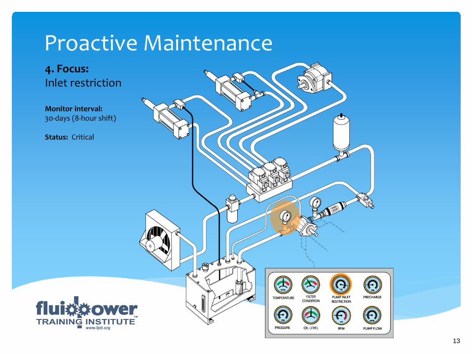
Proactive Maintenance 4. Focus: Inlet restriction Monitor interval: 30-days (8-hour shift) Status: Critical
13

Proactive Maintenance Primary responsibility: Technician Best practice(s): • Fluid power designers must break with tradition and design-in devices for performing non-invasive pump inlet restriction monitoring • Systems with zero-flow on idle pumps (pressure compensated and load sensing) should be equipped with by-pass valves to facilitate certain performance checks and adjustments – including pump inlet restriction. • Engineers MUST not assume pump inlet restriction is correct. Engineers MUST check pump inlet restriction under “worst-case” conditions. • Manufacturers MUST provide accurate pump inlet restriction specifications. Current practice is to copy pump manufacturers’ specifications and insert in machine service manual. • Pump inlet restriction point-of-reference (POR) must be established by trained technicians . • Technicians MUST receive training in operation at the inlet side of a pump. • Technicians MUST know cause and effect of abnormal pump inlet restriction.
• Technicians must know how problems at the inlet side of a pump can cause accidents that can lead to severe injury, death, and extensive property damage. Safety hazard level: Moderate to critical Optimum pump inlet restriction: Type of pump, fluid temperature, and altitude dependent Performance benefits: • Safety • Reliability • Increased pump life • Avoids systemic failure • Consistent operation Failure to perform (FTP) possible outcome(s): • Unsafe system • Systemic failure • Possible air contamination of the oil
14

Proactive Maintenance Survey regarding pump inlet restriction: Technicians: Participants ten (10). • Could describe how the inlet side of a pump functions – 10% • Could describe maximum inlet restriction for piston, gear, and vane pumps – 0% • Has performed an inlet restriction test on a hydraulic pump – 0% • Could explain instruments needed to perform a pump inlet restriction test – 0% • Could explain how to determine a pump’s inlet restriction point-of-reference – 0% • Knew their pump’s inlet restriction point-of- reference – 0% • Could explain cause and effect of excessive of low pump inlet restriction – 10% • Could explain the difference between cavitation and pseudo-cavitation – 0% • Received training in how the inlet side of a pump functions – 5%
Interesting fact: When removed from service and disassembled, the internal components of over 60% of open-loop pumps demonstrated signs of cavitation.
• Could explain where pressure comes from – 10% • Owned, or had access to, a vacuum gauge – 0% • Had ever used a vacuum gauge to check the inlet side of a pump – 0% • Had ever observed a connector/valve of any type at the inlet side of a pump to facilitate non- invasive pump inlet restriction test: 0%
15
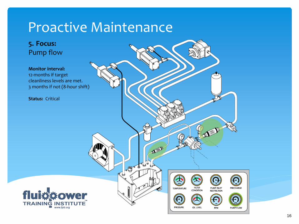
Proactive Maintenance 5. Focus: Pump flow Monitor interval: 12-months if target cleanliness levels are met. 3 months if not (8-hour shift) Status: Critical
16

Proactive Maintenance Primary responsibility: Technician Best practice(s): • Fluid power designers must break with tradition and design-in devices for readily installing flow meters in pump outlet ports. • Systems with zero-flow on idle pumps (pressure compensated and load sensing) should be equipped with by-pass valves to facilitate pump set-up, and performance testing. • The fluid power industry should adopt the following standard for testing the performance of ALL hydraulic pumps: internal and external drain types: Techniques: - In-circuit - Direct access Flow meter location: In series with pump outlet port transmission line Simultaneous monitoring: - Pump flow - Pump speed (RPM) - Pump inlet restriction
• Case flow performance testing should be strongly discouraged. • Pump specifications should be displayed on the machine. • Manufacturers should provide pump performance graphs that display normal, marginal, and unsatisfactory pump flow rates. • The fluid power industry should break away from the tradition of run-to-fail. • Manufacturers must refrain from recommending open line “receptacle” testing. • Technicians must be trained to execute safe and accurate pump performance tests. • Technicians must be trained to properly document pump performance test. • Operators should be trained to identify symptoms of pump wear. Safety hazard level: Critical Optimum pump performance: Based on pump type, oil temperature, inlet restriction, and speed (RPM). Performance benefits: • Safe operation • Reliability • Avoids cost prohibitive systemic failure
17

Proactive Maintenance Failure to perform (FTP) possible outcome(s): • Unsafe operation • Systemic failure Survey regarding pump flow: Technicians: Participants fifty (50). • Could describe how to correctly perform a pump flow test – 10% • Owned or had access to a flow meter – 5% • Could explain what the term “volumetric efficiency” means – 5% • Could describe the volumetric efficiencies of piston, vane, and gear pumps – 5% • Of those who had performed a pump flow test percentage that associated pump inlet restriction and speed (RPM) with a pump flow test – 0% • Could explain threshold at which a pump must be replaced – 0% • Believed a case flow test was 100% accurate – 100% • Had performed pump a performance test as a component of scheduled maintenance – 1% • Could describe why a pump performance test needed to be performed at maximum pressure – 5% • Could recall the flow rates for a pump (s) on machinery they maintained – 2%
Interesting fact: • 95% of the participants had never seen a flow meter. • 85% believed it was possible to find a problem associated with actuator speed with a pressure gauge.
18
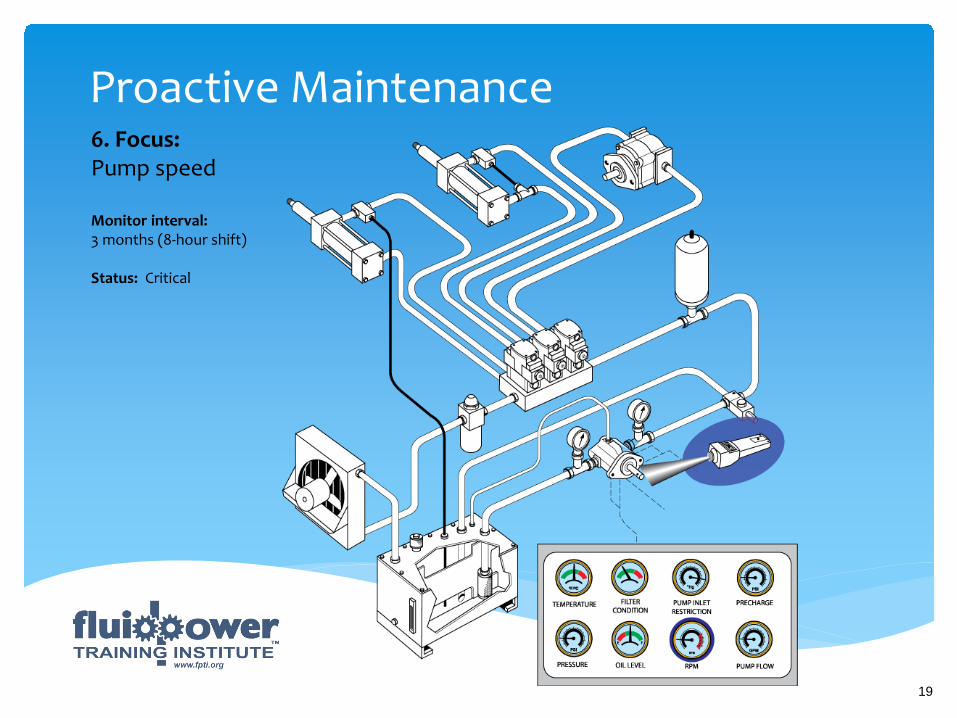
Proactive Maintenance 6. Focus: Pump speed Monitor interval: 3 months (8-hour shift) Status: Critical
19
Proactive Maintenance Primary responsibility: Technician Best practice(s): • Pump speed • Manufacturers MUST provide accurate pump speed specifications. • Technicians MUST be trained to recognize symptoms associated with increases and decreases in pump speed. • Technicians must be trained to be able to associate increases and decreases in pump flow with increases and decreases in prime mover speed. • Technicians must be trained to associate increases in pump speed and flow with pump inlet restriction. Safety hazard level: Moderate Optimum pump speed: As recommended by manufacturer Performance benefits: • Safety • Maximum efficiency • Reliability • Increased pump life • Avoids systemic failure
Failure to perform (FTP) possible outcome(s): • Unsafe operation • Systemic failure Survey regarding pump speed: Technicians: Participants fifty (50). • Checked pump speed as a component of scheduled maintenance – 0% • Could describe the relationship of pump speed to pump flow – 10% • Could describe cause and effect of excessive pump speed – 0% • Could describe maximum inlet restriction for piston, gear, and vane pumps – 0%
20
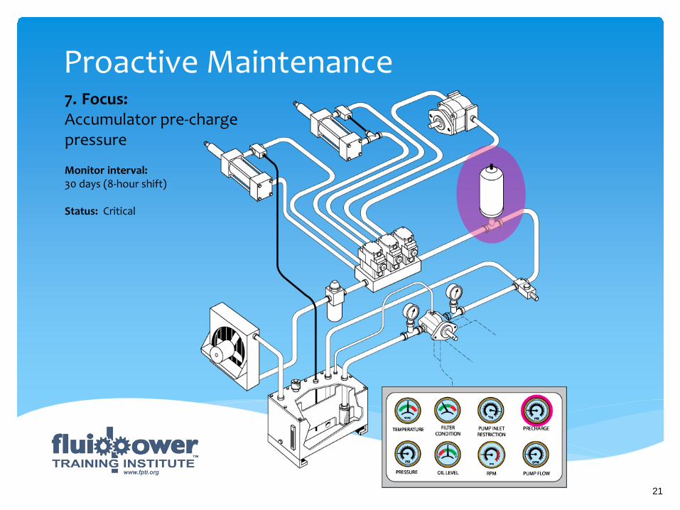
Proactive Maintenance 7. Focus: Accumulator pre-charge pressure Monitor interval: 30 days (8-hour shift) Status: Critical
21

Proactive Maintenance Primary responsibility: Technician Best practice(s): • All workers who service, repair, and maintain accumulators must be properly trained. Most workers don’t associate a hydraulic system with a gas charged vessel. • Accumulator pre-charge pressure should be monitored at least every thirty days especially if the accumulator(s) are for the purpose of emergency back-up in the event of a hydraulic system failure, or a loss of input power. • Maintenance personnel must be equipped with correct nitrogen pre-charge instruments. • Nitrogen bottles must be equipped with pressure regulators and pressure gauges. • NEVER connect a nitrogen bottle to an accumulator without a pressure regulator, which must be set at no more than 100 PSI (6.9 bar) above recommended nitrogen pre-charge pressure. Back pressuring a hydraulic system with high-pressure nitrogen can lead to an accident that can result in severe injury, death, or substantial property damage.
• Do not attempt to service or repair a nitrogen accumulator unless you are trained and authorized. • Do not ship a pre-charged accumulator in a courier van. • If you do not know what the correct nitrogen pre- charge pressure is, pre-charge to 50% of the hydraulic systems pressure relief valve setting. • Do not use oxygen or air to pre-charge an accumulator. Safety hazard level: Critical Recommended accumulator pre-charge pressure: Per manufacturers’ specifications Performance benefits: • Safe operation • Increased response • Increased pump life • Avoids systemic failure • Consistent operation
22
Proactive Maintenance Failure to perform (FTP) possible outcome(s): • Unsafe operation • Systemic failure Survey regarding accumulator pre-charge pressure: Technicians: Participants fifty (50). • Could explain the relationship of pre-charge pressure to usable volume – 0% • Could explain cause and effect of excessive pre-charge pressure – 0% • Could explain cause and effect of low pre-charge pressure – 0% • Had received formal training in accumulators and safe accumulator charging procedures – 20%
23

Proactive Maintenance 8. Focus: Filter condition indicator/filter service Monitor interval: 8-hours Status: Critical
24
Proactive Maintenance Primary responsibility: Technician Secondary responsibility: Machine operator Best practice(s): • All filters should be fitted with differential pressure indicators. • Filter service should be triggered by condition indicator. • Maintenance personnel must be trained to understand cause and effect of changing filters prematurely. • Maintenance personnel must be trained to understand cause and effect of ignoring filter change schedule. • Maintenance personnel must be thoroughly conversant with ISO4406. • Maintenance personnel must be familiar with filter beta ratios. • Maintenance personnel must be able to set a target cleanliness level for all types of hydraulic systems. Safety hazard level: Moderate to critical Filter change interval: According to pressure differential indicator
Performance benefits: • Safety • Reliability • Increased pump life • Avoids systemic failure • Consistent operation • Reduced operating costs Failure to perform (FTP) possible outcome(s): • Unsafe system • Zero oil conditioning • Systemic failure Survey regarding filter condition indicators: Technicians: Participants fifty (50). • Were aware of function of filter condition indicator – 70% • Changed filter elements based on filter condition indicators – 1% • Could explain ISO 4406 • Could describe what the term “beta ratio” means – 1% • Could explain how to set a target cleanliness level for a given hydraulic system – 0% • Believed oil is cleaned on a single pass through an element – 95% • Did not know it was poor practice to “wash” filter screens and filter canisters in a solvent tank – 95% • Were not aware that brand new oil is unsuitable for a hydraulic system – 98%
25
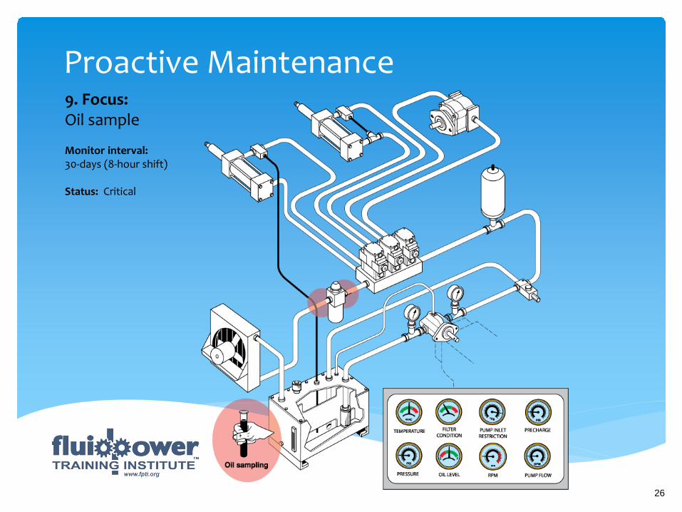
Proactive Maintenance 9. Focus: Oil sample Monitor interval: 30-days (8-hour shift) Status: Critical
26
Proactive Maintenance Primary responsibility: Technician Best practice(s): • Fluid power designers must break with tradition and design-in devices for drawing oil samples. • Must locate oil sampling valves at the inlet side of return line filter. • Maintenance personnel must be trained to draw oil samples from a hydraulic system • Closed loop systems must have oil sampling valves in the loop. Safety hazard level: Critical Performance benefits: • Safety • Reliability • Increased component life • Avoids systemic failure • Consistent operation
Failure to perform (FTP) possible outcome(s): • Unsafe system • Systemic failure Survey regarding hydraulic oil sample: Technicians: Participants fifty (50). • Had attended reliability maintenance course – 1% • Had been formally trained to draw an oil sample – 1% • Was aware of what happened to an oil sample in a lab – 5% • Could read and analyze an oil sample – 1% • Could reconcile and oil sample with a target cleanliness level – 0% • Were involved with discussions about outcomes of oil samples – 5% • Knew what a laser count is – 1% • Knew what a spectrophotometer is – 1% • Knew the terminal volume of water in oil – 0%
27

Proactive Maintenance 10. Focus: MicroLeak detection Monitor interval: 3 months (8-hour shift) Status: Critical
28
Proactive Maintenance Primary responsibility: Technician Best practice(s): • The fluid power industry must wean itself from the run- to-fail (RTF) mentality. • Maximum hydraulic system performance can be maintained if component wear rates are monitored on a scheduled maintenance basis. • MicroLeak testing is the only safe and effective technique for analyzing leakage rates in directional control valves, pressure relief valves, check valves, and cylinders. • MicroLeak testing can determine acceptable, marginal, and unacceptable component leakage rates without manufacturer specified leakage rates. • MicroLeak testing can be performed with the prime mover safely locked and tagged. • The average time it takes to perform a MicroLeak Test is fifteen (15) minutes. • There is no need to remove or disassemble a component to perform a MicroLeak test. Safety hazard level: Moderate to critical
Pressure/time test: Directional control valve: 60 seconds Check valves: 60 seconds Pressure control valves: 60 seconds Performance benefits: • Safety • Reliability • Increased pump life • Avoids systemic failure • Consistent operation Failure to perform (FTP) possible outcome(s): • Unsafe system • Systemic failure • Possible air contamination of the oil Survey regarding hydraulic oil sample: Technicians: Participants fifty (50). • Could describe what a MicroLeak test is – 0% • Could explain how to performance test a directional control valve – 0% • Could explain how to performance test a pressure control valve – 0% • Could explain how to performance test a check valve – 0%
29

Proactive Maintenance
30

Proactive Maintenance “Get To Know the Patient!”
Presented by: Rory S. McLaren
Fluid Power Training Institute™ http://www.fpti.org
Copyright © 2013
31