Embed Size (px)
Citation preview
MIT Rocket Team USLI 2012-2013 CDR Version: Final
Do Not Copy Without Permission 1
PROJECT AI3R: AERO ION INFRARED INTELLIGENCE ROCKET
USLI CDR 2012-2013
JANUARY 14, 2012
MIT Rocket Team USLI 2012-2013 CDR Version: Final
Do Not Copy Without Permission 2
TABLE OF CONTENTS
1 Basic Personal Information ..................................................................................... 10
1.1 School Information ........................................................................................... 10
1.2 Facilities and Equipment .................................................................................. 13
1.2.1 Lab Space ..................................................................................................... 13
1.2.2 Personnel and Equipment Needed ............................................................... 13
1.2.3 Computer Equipment .................................................................................... 14
1.2.4 Web Presence .............................................................................................. 15
1.2.5 Implementation of Architectural and Transportation Barriers Compliance
Board Electronic and Information Technology (EIT) Accessibility Stanards ............ 15
2 Summary of CDR Report ........................................................................................ 21
2.1 Team Summary ................................................................................................ 21
2.1.1 Team Name and Mailing Address ................................................................. 21
2.1.2 Location ........................................................................................................ 21
2.1.3 Mentor ........................................................................................................... 21
2.2 Launch Vehicle Summary ................................................................................ 22
2.2.1 Size and Mass .............................................................................................. 22
2.2.2 Motor Choice ................................................................................................ 22
2.2.3 Rail Size ........................................................................................................ 23
2.2.4 Recovery System .......................................................................................... 23
2.2.5 Milestone Review Flysheet ........................................................................... 23
2.3 Payload Summary ............................................................................................ 23
3 Changes Made ........................................................................................................ 24
3.1 Since Proposal ................................................................................................. 24
3.2 Since PDR........................................................................................................ 24
MIT Rocket Team USLI 2012-2013 CDR Version: Final
Do Not Copy Without Permission 3
4 Vehicle Criteria ........................................................................................................ 26
4.1 Selection, Design, and Verification of Launch Vehicle ..................................... 26
4.1.1 Mission Motivation ........................................................................................ 26
4.1.2 Mission Statement ........................................................................................ 27
4.1.3 Constraints .................................................................................................... 27
4.1.4 Mission Requirements .................................................................................. 28
4.1.5 System Requirements ................................................................................... 29
4.1.6 Mission Success Criteria ............................................................................... 30
4.1.7 Milestones ..................................................................................................... 30
4.1.8 System Level design review ......................................................................... 30
4.1.9 Verification Plan ............................................................................................ 31
4.1.10 Manufacturing and Assembly Plans .......................................................... 35
4.1.11 Design Integrity .......................................................................................... 37
4.1 Subscale Flight Results .................................................................................... 40
4.1.1 Impact on Full Scale Vehicle ......................................................................... 41
4.2 Structures Subsystem ...................................................................................... 41
4.2.1 Airframe ........................................................................................................ 42
4.3 Propulsion Subsystem ..................................................................................... 61
4.4 Avionics Subsystem ......................................................................................... 62
4.4.1 Hardware ...................................................................................................... 62
4.4.2 Software ........................................................................................................ 63
4.4.3 Mounting and Placement .............................................................................. 63
4.5 Recovery Subsystem ....................................................................................... 64
4.5.1 Overview ....................................................................................................... 64
4.5.2 Details ........................................................................................................... 65

MIT Rocket Team USLI 2012-2013 CDR Version: Final
Do Not Copy Without Permission 4
4.5.3 Deployment ................................................................................................... 67
4.5.4 Test Results .................................................................................................. 70
4.6 Communications Subsystem ............................................................................ 70
4.7 Power Subsystem ............................................................................................ 70
4.8 Mission Performance Predictions ..................................................................... 71
4.8.1 Mission Performance Criteria ........................................................................ 71
4.8.2 Flight Profile Simulation ................................................................................ 71
4.8.3 Stability Predictions ....................................................................................... 76
4.8.4 Kinectic Energy ............................................................................................. 77
4.9 Interfaces and Integration ................................................................................ 77
4.9.1 Procedure ..................................................................................................... 77
4.9.2 Tasking and Integration Schedule................................................................. 79
4.9.3 Internal Paylaod Interfaces (Precision Fit and Compatibility of Elements) .... 79
4.9.4 Payload Installation and Removal ................................................................. 80
4.9.5 Simplicity of integration procedure ................................................................ 80
4.10 Launch Concerns and Operation Procedures .................................................. 80
4.10.1 Summary of Rocket Assembly ................................................................... 80
4.10.2 Launch System and Platform ..................................................................... 80
4.10.3 Recovery Preparation ................................................................................ 90
4.10.4 Motor Preparation ...................................................................................... 90
4.10.5 Igniter Installation ...................................................................................... 91
4.10.6 Launcher Setup ......................................................................................... 91
4.10.7 Setup on Launcher .................................................................................... 91
4.10.8 TroubleShooting ........................................................................................ 91
4.10.9 Post Flight Inspection ................................................................................ 92
MIT Rocket Team USLI 2012-2013 CDR Version: Final
Do Not Copy Without Permission 5
4.11 Safety and Environment (Vehicle) .................................................................... 93
4.11.1 Identification of Safety Officers .................................................................. 93
4.11.2 Rocket Risks .............................................................................................. 93
4.11.3 Safety Analysis .......................................................................................... 95
4.11.4 Analysis of Failure Modes and Mitigations................................................. 95
4.11.5 Personal Hazards ...................................................................................... 98
4.11.6 Environmental Concerns ......................................................................... 102
5 Payload Criteria ..................................................................................................... 102
5.1 Selection, Design, and Verification of Payload Experiment ............................ 103
5.1.1 Mission Motivation ...................................................................................... 103
5.1.2 Mission Statement ...................................................................................... 104
5.1.3 Constraints .................................................................................................. 104
5.1.4 Mission Requirments .................................................................................. 105
5.1.5 System Requirements ................................................................................. 106
5.1.6 Requirement Verification By Design ........................................................... 106
5.1.7 Payload Hypothesis .................................................................................... 106
5.1.8 Success Criteria .......................................................................................... 106
5.1.9 Milestone Schedule ..................................................................................... 107
5.1.10 Overview of Flight Operations ................................................................. 107
5.1.11 Overview of Data Acquisition Plan ........................................................... 109
5.1.12 Overview: SPRITE ................................................................................... 111
5.1.13 Overview: HALO ...................................................................................... 140
5.1.14 Safety ...................................................................................................... 149
5.1.15 Instrument Percision and Measurement Repeatability ............................ 150
5.1.16 Expected Final Data ................................................................................ 151

MIT Rocket Team USLI 2012-2013 CDR Version: Final
Do Not Copy Without Permission 6
5.1.17 Design Integrity ........................................................................................ 151
5.2 Payload Concept Features and Definition ...................................................... 155
5.2.1 Creativity and Originality ............................................................................. 155
5.2.2 Uniqueness and Significances .................................................................... 155
5.2.3 Suitable Level of Challenge ........................................................................ 156
5.3 Science Value ................................................................................................ 156
5.3.1 Science Payload Objectives ....................................................................... 156
5.3.2 Payload Success Criteria ............................................................................ 157
5.3.3 Experimental Logic, Approach, and Method of Investigation ...................... 157
5.3.4 Test Measurements, Variables, and Controls ............................................. 158
5.3.5 Relevance of Expected Data ...................................................................... 160
5.3.6 Accuracy and Error Analysis ....................................................................... 160
5.3.7 Preliminary Experiment Process Procedures .............................................. 161
5.4 Safety and Environment (Payload) ................................................................. 162
5.4.1 Identification of Safety Officers ................................................................... 162
5.4.2 Safety Analysis ........................................................................................... 162
5.4.3 Analysis of Failure Modes and Mitigations .................................................. 162
5.4.4 Personal Hazards ....................................................................................... 162
5.4.5 Environmental Concerns ............................................................................. 163
6 Safety Plan ............................................................................................................ 164
6.1 Procedures for NAR/TRA Personnel to Perform ............................................ 164
6.2 Hazard Recognition and Accident Avoidance ................................................ 164
6.3 Outline of hazard Recognition Briefing ........................................................... 165
6.4 Pre-launch Briefing ......................................................................................... 167
6.5 Caution Statements ........................................................................................ 167

MIT Rocket Team USLI 2012-2013 CDR Version: Final
Do Not Copy Without Permission 7
6.6 Cognizance of Federal, State, and Local Laws Regarding Rocet Laucnh and
Motor Handling ......................................................................................................... 167
6.7 Purchasing and Handing Rocket Motors ........................................................ 168
6.8 Transportation of Rocket to Hunstville ........................................................... 168
6.9 Safety Agreement .......................................................................................... 168
7 Project Plan ........................................................................................................... 169
7.1 Budget Plan.................................................................................................... 169
7.2 Funding Plan .................................................................................................. 170
7.3 Timeline ......................................................................................................... 170
7.4 Community Support Plan ............................................................................... 172
7.4.1 Expertise ..................................................................................................... 172
7.4.2 Equipment/Supplies .................................................................................... 172
7.4.3 Monetary Donations .................................................................................... 172
7.4.4 Services ...................................................................................................... 172
7.4.5 Advertisements ........................................................................................... 172
7.4.6 Partners with Schools ................................................................................. 173
7.4.7 Partners with Industry ................................................................................. 173
7.5 Major Progammatic Challenges and Solutions............................................... 173
7.6 Project Sustainability Plan .............................................................................. 173
7.6.1 Aquiring and Maintaining Partnerships ....................................................... 173
7.6.2 Engaging Students in Rocketry ................................................................... 173
7.6.3 Partners in Industry/commmunity................................................................ 173
7.6.4 Recruitment of Students ............................................................................. 174
7.6.5 Funding Sustainability ................................................................................. 174
7.7 Outreach Plan and Educational Engagement ................................................ 174
MIT Rocket Team USLI 2012-2013 CDR Version: Final
Do Not Copy Without Permission 8
7.7.1 Purpose of Community Outreach ................................................................ 174
7.7.2 Current Schedule ........................................................................................ 174
7.7.3 Rocket Dat at the Boston Museum of Science ............................................ 175
7.7.4 Rocket Day at the MIT Museum.................................................................. 176
7.7.5 MIT Splash and Spark Weekends ............................................................... 176
7.7.6 Lab Tours and Rocketry WorkShops .......................................................... 178
7.7.7 Work with Massachusetts Afterschool Partnership (MAPS) ........................ 178
7.7.8 Science on the Street .................................................................................. 179
8 Conclusion ............................................................................................................ 179
9 Appendix ............................................................................................................... 180
9.1 Rocket Master Equipment List ....................................................................... 180
9.2 Quadrotor Bill of Materials .............................................................................. 181
9.3 Schedule ........................................................................................................ 182
9.4 CAD Models ................................................................................................... 184
9.5 Mechanical Drawings ..................................................................................... 184
9.6 Circuit Schematics ......................................................................................... 184
9.7 PCB Designs .................................................................................................. 184
9.8 Manufacturing Plan ........................................................................................ 184
9.9 Code Overview ............................................................................................... 184
9.10 NIMBUS ......................................................................................................... 184
NIMBUS ...................................................................................................................... 184
Mission Motivation ................................................................................................. 184
Mission Statement .................................................................................................... 184
Mission Requirments ................................................................................................ 184
Payload Details ........................................................................................................ 185
MIT Rocket Team USLI 2012-2013 CDR Version: Final
Do Not Copy Without Permission 9
Theory ................................................................................................................... 185
List of Components ............................................................................................... 188
Operations During Rocket Ascent ......................................................................... 191
Budget ................................................................................................................... 191
9.11 Descope Plan ................................................................................................. 192
9.12 Observed Regulations and Safety Requirements .......................................... 192
9.13 Signed Documents ......................................................................................... 192
9.13.1 Safety Agreements .................................................................................. 192
9.13.2 Educational Engagement Form ............................................................... 194
9.14 FAA Regulations ............................................................................................ 196
9.15 High Power Rocket Safety Code .................................................................... 200
10 Misc Sample Documents ................................................................................... 203
10.1 Advertisements .............................................................................................. 203
10.1.1 Official 2012 Departmental Poster ........................................................... 203
10.1.2 Multimedia Display .................................................................................. 203
10.1.3 Briggs Field Flyer ..................................................................................... 204
10.1.4 MIT Tech Newspaper .............................................................................. 204
10.2 Outreach Activity ............................................................................................ 204
10.2.1 Lesson Plans ........................................................................................... 204
10.2.2 Activity Sheets ......................................................................................... 204
10.2.3 Sign-In Sheets ......................................................................................... 204
11 Works Cited ....................................................................................................... 204
MIT Rocket Team USLI 2012-2013 CDR Version: Final
Do Not Copy Without Permission 10
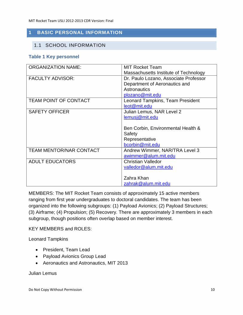
1 BASIC PERSONAL INFORMATION
1.1 SCHOOL INFORMATION
Table 1 Key personnel
ORGANIZATION NAME: MIT Rocket Team Massachusetts Institute of Technology
FACULTY ADVISOR: Dr. Paulo Lozano, Associate Professor Department of Aeronautics and Astronautics [email protected]
TEAM POINT OF CONTACT Leonard Tampkins, Team President [email protected]
SAFETY OFFICER Julian Lemus, NAR Level 2 [email protected] Ben Corbin, Environmental Health & Safety Representative [email protected]
TEAM MENTOR/NAR CONTACT Andrew Wimmer, NAR/TRA Level 3 [email protected]
ADULT EDUCATORS Christian Valledor [email protected] Zahra Khan [email protected]
MEMBERS: The MIT Rocket Team consists of approximately 15 active members
ranging from first year undergraduates to doctoral candidates. The team has been
organized into the following subgroups: (1) Payload Avionics; (2) Payload Structures;
(3) Airframe; (4) Propulsion; (5) Recovery. There are approximately 3 members in each
subgroup, though positions often overlap based on member interest.
KEY MEMBERS and ROLES:
Leonard Tampkins
President, Team Lead
Payload Avionics Group Lead
Aeronautics and Astronautics, MIT 2013
Julian Lemus
MIT Rocket Team USLI 2012-2013 CDR Version: Final
Do Not Copy Without Permission 11
Head Safety Officer
Airframe Group Lead
Treasurer
Aeronautics and Astronautics, MIT 2013
Ben Corbin
Assistant Safety Officer
Aeronautics and Astronautics; Earth, Atmospheric, and Planetary Sciences, PhD
candidate
Eric Peters
Propulsion Group Lead
S.M. Canidate with the MIT Space Systems Laboratory
Matt Vernacchia
Payload Group Lead
Aeronautics and Astronautics, MIT 2015
Jed Storey
UAV Specialist
Aeronautics and Astronautics, MIT 2013
Henna Jethani
Aeronautics and Astronautics, MIT 2014
Kayla Esquivel
Computer Science, MIT 2015
Norman Cao
Aeronautics and Astronautics and Physics, MIT 2015
Christopher Maynor
Aeronautics and Astronautics, MIT 2015
Paco Holguin
Aeronautics and Astronautics, MIT 2016
MIT Rocket Team USLI 2012-2013 CDR Version: Final
Do Not Copy Without Permission 12
James D Logan
Aeronautics and Astronautics, MIT 2015
Ceili A Burdhimo
Aeronautics and Astronautics, MIT 2015
Rin Yunis
Aeronautics and Astronautics, MIT 2015
Steven Gordan
Foreign National
Aeronautics and Astronautics, MIT 2014
Sally A Miller
Aeronautics and Astronautics, MIT 2015
Joshua N Millings
Aeronautics and Astronautics, MIT 2016
Todd Sheerin
Physics, Harvard 2011
Aeronautics and Astronautics, MIT
Aaron L Ashley
Aeronautics and Astronautics, MIT 2015
Zaira Garate
Aeronautics and Astronautics, MIT 2015
Alexander Y Chen
Aeronautics and Astronautics, MIT 2015
Corinn M Herrick
Aeronautics and Astronautics, MIT 2015
Emily Thomson
MIT Rocket Team USLI 2012-2013 CDR Version: Final
Do Not Copy Without Permission 13
Aeronautics and Astronautics, MIT 2015
Adrianna Rodriguez
Aeronautics and Astronautics, MIT 2015
1.2 FACILITIES AND EQUIPMENT
1.2.1 LAB SPACE
The MIT Rocket Team has been assigned its own lab space on the main campus to
conduct all activities associated with the design, fabrication, and storage of large-scale
competitive rockets, and science payloads. The team’s lab space in Building 17 (The
Wright Brothers Wind Tunnel Building: http://whereis.mit.edu/?go=17) of the MIT
campus serves as the primary workspace, meeting space, and a secure storage
location. The Lab is part of the campus Environmental Health and Safety system and,
as such, all health and safety standards are followed in the lab. The lab is open during
normal institute hours, and core members can be issued a key to the building as
needed for 24-hour access. The lab is furnished with various hand tools and select
power tools commonly used for rocket fabrication.
The Rocket team also has access to the MIT Gelb Lab in MIT Building 33. This lab
space serves as a common work area for the entire department of Aeronautics and
Astronautics at MIT. The lab includes a full machine shop, group meeting spaces,
worktables, and a small-scale wind tunnel for student use. In the machine shop team
members are allowed to work under the guidance of a full time instructor, ensuring
safety and accuracy in all manners of work. The wind tunnel is also open to any student
wishing to use it, and may be used for the rocket team as needed. The Gelb Lab is
open 24 hours a day to all members of the Department of Aeronautics and Astronautics,
and special access may be requested on a case-by-case basis. The machine shop is
open from 9am until 5pm on weekdays, and is limited to course related work and
projects related to the department, including the Rocket Team.
1.2.2 PERSONNEL AND EQUIPMENT NEEDED
The MIT Rocket Team, is fully student led, and as such will be under the direction of
Team President Leonard Tampkins. To ensure all federal, state, and institute rules are
followed the team advisor, Professor Lozano, and Safety Officers, Julian Lemus and
Ben Corbin will review all steps of the design, construction and testing process. Flight-
testing of the rockets will be conducted with assistance of the local NAR chapter,
MIT Rocket Team USLI 2012-2013 CDR Version: Final
Do Not Copy Without Permission 14
CMASS, and more distant rocket clubs, MMMSC, CRMRC, METRA and MDRA.
Individual subcomponent testing will be conducted on the Massachusetts Institute of
Technology campus, at various suitable locations. The MIT Rocket Team will obtain any
and all materials necessary to complete the USLI competition while following all stated
rules. For additional help, we have contacts with members of MDRA and have multiple
members on the team with high power rocketry experience.
1.2.3 COMPUTER EQUIPMENT
All members of the MIT Rocket Team have access to a variety of computers on campus
to aid in the design, simulation, modeling, and analysis of our designs. Although the
Rocket Team does not maintain a computer specifically for the team, many computers
are made available to the members.
The MIT computer network, MITnet, consists of a wireless network that covers 100% of
the campus, as well as all dormitories and MIT fraternities, sororities, and independent
living groups. Along with access to high speed internet, MITnet includes 345 computers,
known as Athena Workstations, scattered across campus, that are open to all members
of the MIT community. A majority of these Athena workstations run a customized Linux
distribution [named Athena], however there are also traditional Windows, and Mac
machines available. All Athena workstations have access to a wide range of software
made available to students for free.
With access to the Athena and other campus licensing agreements all members of the
MIT Rocket Team are able to use sophisticated software including but not limited to:
MATLAB
Mathematica
SolidWorks
FEMAP/NEiNASTRAN
Maple
Altium
Microsoft Office
In addition to software available campus wide, the MIT Rocket Team also purchased
floating licenses of RockSim, which is used extensively for initial design and modeling.
Furthermore, MIT Rocket Team members may also use their own personal computers
when working on USLI related items. A majority of all work is done by members on
these personal machines. As such the computer resources available to the team are
virtually limitless, and are available to us at all times. Last but not least, members of the
MIT Rocket Team USLI 2012-2013 CDR Version: Final
Do Not Copy Without Permission 15
MIT Rocket Team will adhere to any and all regulations concerning computer systems
as dictated by the USLI organizers.
1.2.4 WEB PRESENCE
In accordance with USLI rules, the MIT Rocket Team has established a website that will
host all information related to the USLI project. The website is hosted by dedicated
machines on the MIT network, and is accessible at: http://web.mit.edu/rocketteam. The
text only version of the site can be found here:
http://www.textise.net/showText.aspx?strURL=http%253A//web.mit.edu/rocketteam/ww
w/index.html.
1.2.5 IMPLEMENTATION OF ARCHITECTURAL AND TRANSPORTATION
BARRIERS COMPLIANCE BOARD ELECTRONIC AND INFORMATION
TECHNOLOGY (EIT) ACCESSIBILITY STANARDS
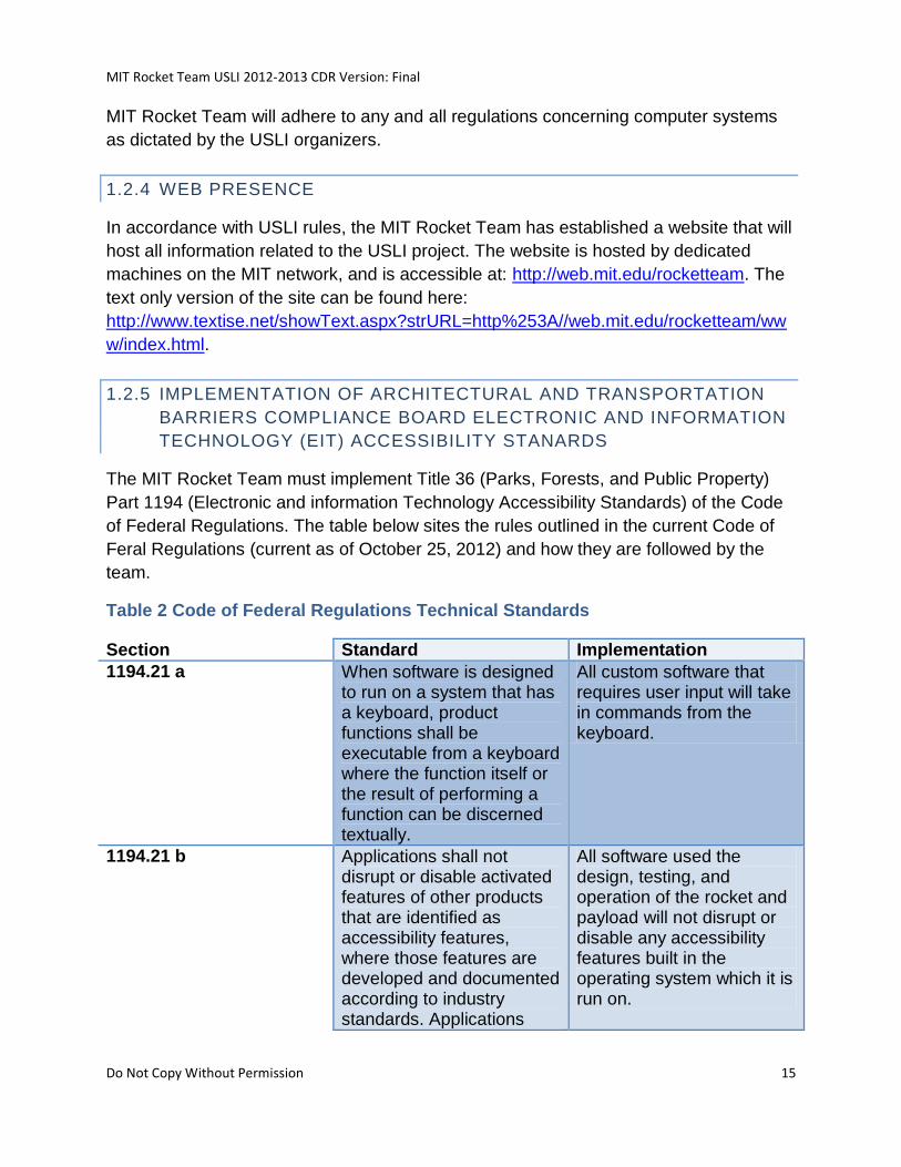
The MIT Rocket Team must implement Title 36 (Parks, Forests, and Public Property)
Part 1194 (Electronic and information Technology Accessibility Standards) of the Code
of Federal Regulations. The table below sites the rules outlined in the current Code of
Feral Regulations (current as of October 25, 2012) and how they are followed by the
team.
Table 2 Code of Federal Regulations Technical Standards
Section Standard Implementation
1194.21 a When software is designed to run on a system that has a keyboard, product functions shall be executable from a keyboard where the function itself or the result of performing a function can be discerned textually.
All custom software that requires user input will take in commands from the keyboard.
1194.21 b Applications shall not disrupt or disable activated features of other products that are identified as accessibility features, where those features are developed and documented according to industry standards. Applications
All software used the design, testing, and operation of the rocket and payload will not disrupt or disable any accessibility features built in the operating system which it is run on.
MIT Rocket Team USLI 2012-2013 CDR Version: Final
Do Not Copy Without Permission 16
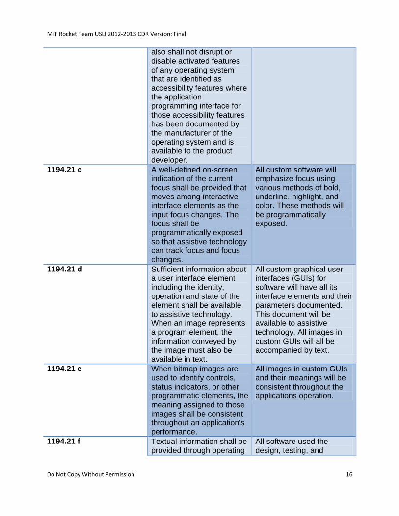
also shall not disrupt or disable activated features of any operating system that are identified as accessibility features where the application programming interface for those accessibility features has been documented by the manufacturer of the operating system and is available to the product developer.
1194.21 c A well-defined on-screen indication of the current focus shall be provided that moves among interactive interface elements as the input focus changes. The focus shall be programmatically exposed so that assistive technology can track focus and focus changes.
All custom software will emphasize focus using various methods of bold, underline, highlight, and color. These methods will be programmatically exposed.
1194.21 d Sufficient information about a user interface element including the identity, operation and state of the element shall be available to assistive technology. When an image represents a program element, the information conveyed by the image must also be available in text.
All custom graphical user interfaces (GUIs) for software will have all its interface elements and their parameters documented. This document will be available to assistive technology. All images in custom GUIs will all be accompanied by text.
1194.21 e When bitmap images are used to identify controls, status indicators, or other programmatic elements, the meaning assigned to those images shall be consistent throughout an application's performance.
All images in custom GUIs and their meanings will be consistent throughout the applications operation.
1194.21 f Textual information shall be provided through operating
All software used the design, testing, and
MIT Rocket Team USLI 2012-2013 CDR Version: Final
Do Not Copy Without Permission 17
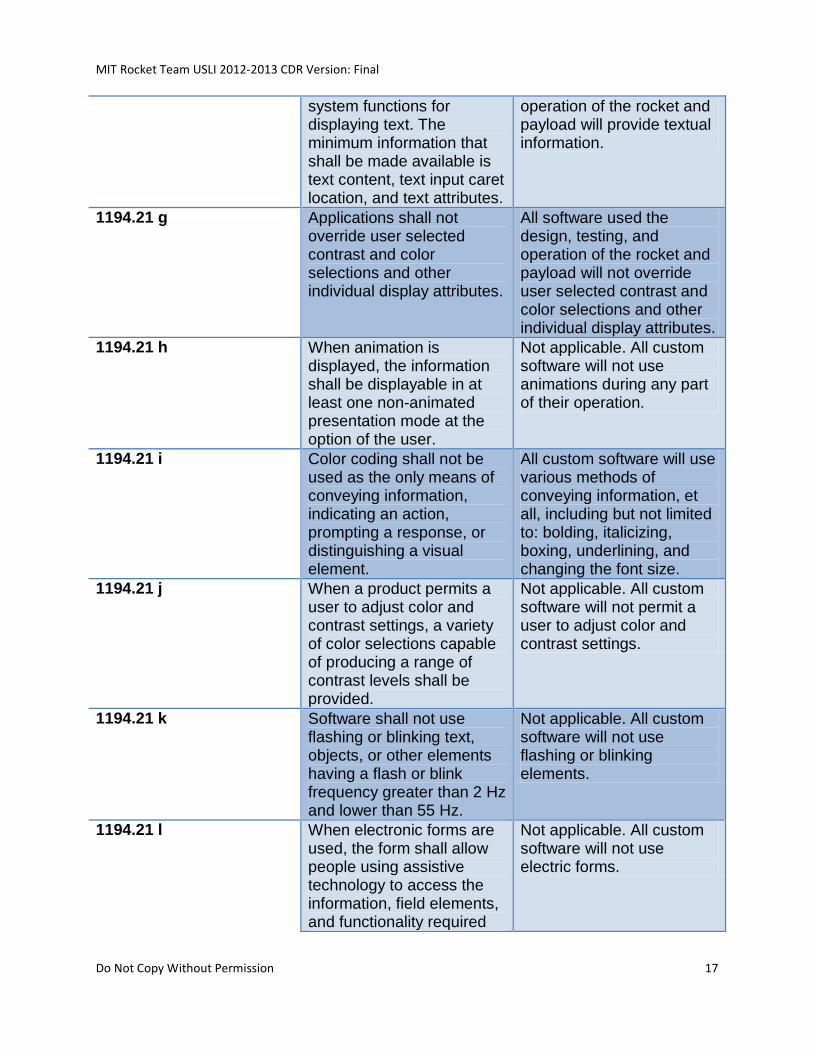
system functions for displaying text. The minimum information that shall be made available is text content, text input caret location, and text attributes.
operation of the rocket and payload will provide textual information.
1194.21 g Applications shall not override user selected contrast and color selections and other individual display attributes.
All software used the design, testing, and operation of the rocket and payload will not override user selected contrast and color selections and other individual display attributes.
1194.21 h When animation is displayed, the information shall be displayable in at least one non-animated presentation mode at the option of the user.
Not applicable. All custom software will not use animations during any part of their operation.
1194.21 i Color coding shall not be used as the only means of conveying information, indicating an action, prompting a response, or distinguishing a visual element.
All custom software will use various methods of conveying information, et all, including but not limited to: bolding, italicizing, boxing, underlining, and changing the font size.
1194.21 j When a product permits a user to adjust color and contrast settings, a variety of color selections capable of producing a range of contrast levels shall be provided.
Not applicable. All custom software will not permit a user to adjust color and contrast settings.
1194.21 k Software shall not use flashing or blinking text, objects, or other elements having a flash or blink frequency greater than 2 Hz and lower than 55 Hz.
Not applicable. All custom software will not use flashing or blinking elements.
1194.21 l When electronic forms are used, the form shall allow people using assistive technology to access the information, field elements, and functionality required
Not applicable. All custom software will not use electric forms.
MIT Rocket Team USLI 2012-2013 CDR Version: Final
Do Not Copy Without Permission 18
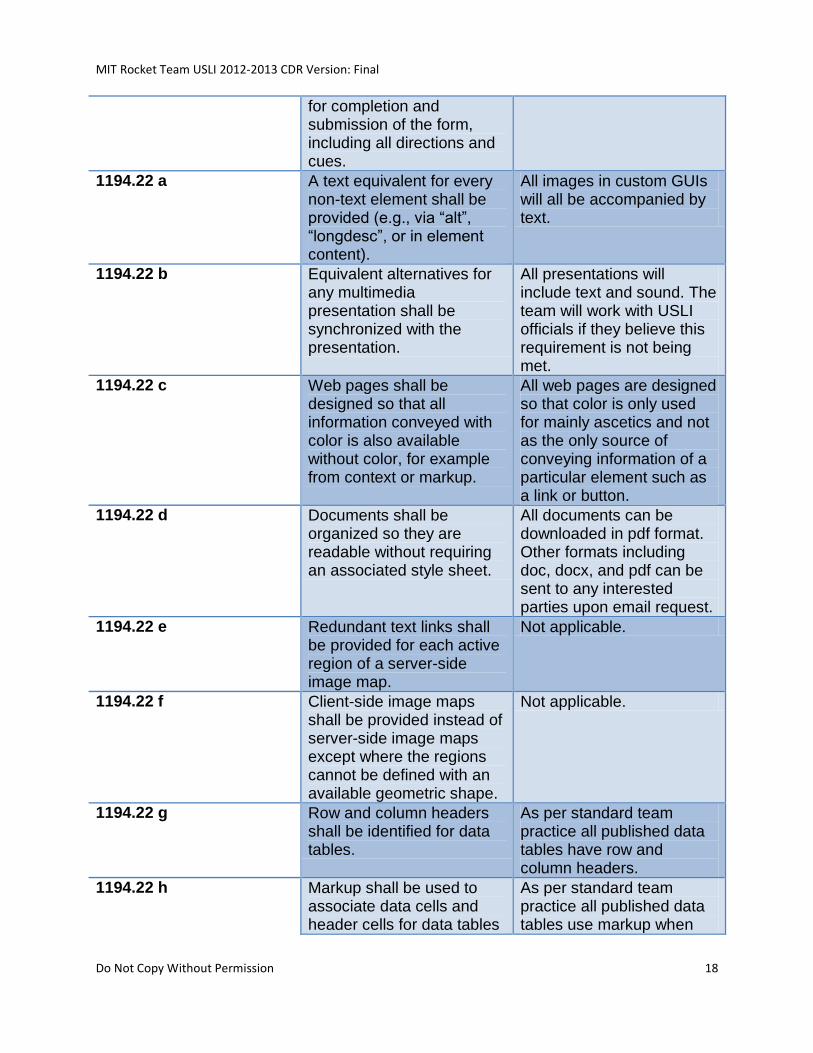
for completion and submission of the form, including all directions and cues.
1194.22 a A text equivalent for every non-text element shall be provided (e.g., via “alt”, “longdesc”, or in element content).
All images in custom GUIs will all be accompanied by text.
1194.22 b Equivalent alternatives for any multimedia presentation shall be synchronized with the presentation.
All presentations will include text and sound. The team will work with USLI officials if they believe this requirement is not being met.
1194.22 c Web pages shall be designed so that all information conveyed with color is also available without color, for example from context or markup.
All web pages are designed so that color is only used for mainly ascetics and not as the only source of conveying information of a particular element such as a link or button.
1194.22 d Documents shall be organized so they are readable without requiring an associated style sheet.
All documents can be downloaded in pdf format. Other formats including doc, docx, and pdf can be sent to any interested parties upon email request.
1194.22 e Redundant text links shall be provided for each active region of a server-side image map.
Not applicable.
1194.22 f Client-side image maps shall be provided instead of server-side image maps except where the regions cannot be defined with an available geometric shape.
Not applicable.
1194.22 g Row and column headers shall be identified for data tables.
As per standard team practice all published data tables have row and column headers.
1194.22 h Markup shall be used to associate data cells and header cells for data tables
As per standard team practice all published data tables use markup when
MIT Rocket Team USLI 2012-2013 CDR Version: Final
Do Not Copy Without Permission 19
that have two or more logical levels of row or column headers.
needed.
1194.22 i Frames shall be titled with text that facilitates frame identification and navigation.
Not applicable.
1194.22 j Pages shall be designed to avoid causing the screen to flicker with a frequency greater than 2 Hz and lower than 55 Hz.
Not applicable. All web pages a designed not to contain elements which would cause the screen to flicker at any frequency.
1194.22 k A text-only page, with equivalent information or functionality, shall be provided to make a web site comply with the provisions of this part, when compliance cannot be accomplished in any other way. The content of the text-only page shall be updated whenever the primary page changes.
A text only version of the webpage can be found in the website section of this document also the team will have a link to this version on the website by Spring 2013.
1194.22 l When pages utilize scripting languages to display content, or to create interface elements, the information provided by the script shall be identified with functional text that can be read by assistive technology.
Not applicable. All webpages do not contain scripting elements as they are written in basic html.
1194.22 m When a web page requires that an applet, plug-in or other application be present on the client system to interpret page content, the page must provide a link to a plug-in or applet that complies with § 1194.21(a) through (l).
Not applicable. All webpages do not require applets or plug-ins.
1194.22 n When electronic forms are designed to be completed on-line, the form shall allow
Not applicable. All custom software and webpages will not use electric forms.
MIT Rocket Team USLI 2012-2013 CDR Version: Final
Do Not Copy Without Permission 20
people using assistive technology to access the information, field elements, and functionality required for completion and submission of the form, including all directions and cues.
1194.22 o A method shall be provided that permits users to skip repetitive navigation links.
Not applicable. All webpages and custom software are designed so that repetitive navigation links do not exist.
1194.22 p When a timed response is required, the user shall be alerted and given sufficient time to indicate more time is required.
Not applicable. All custom software will not have any timed responses.
1194.23 k 1194.26 a 1194.26 b
(k) Products which have mechanically operated controls or keys, shall comply with the following:
(1) Controls and keys shall be tactilely discernible without activating the controls or keys.
(2) Controls and keys shall be operable with one hand and shall not require tight grasping, pinching, or twisting of the wrist. The force required to activate controls and keys shall be 5 lbs. (22.2 N) maximum.
(3) If key repeat is supported, the delay before repeat shall be adjustable to at least 2 seconds. Key repeat rate shall be adjustable to 2 seconds per character.
The ground station support equipment (GSE) has been designed with these standards in mind. For more information be see the GSE section of this documents.
MIT Rocket Team USLI 2012-2013 CDR Version: Final
Do Not Copy Without Permission 21
(4) The status of all locking or toggle controls or keys shall be visually discernible, and discernible either through touch or sound.
1194.26 c When biometric forms of user identification or control are used, an alternative form of identification or activation, which does not require the user to possess particular biological characteristics, shall also be provided
Not applicable. Biometric forms of user identification will not be used.
1194.26 d Where provided, at least one of each type of expansion slots, ports and connectors shall comply with publicly available industry standards.
Only publicly available ports and connectors which comply industry standards will be used.
2 SUMMARY OF CDR REPORT
2.1 TEAM SUMMARY
2.1.1 TEAM NAME AND MAILING ADDRESS
MIT Rocket Team
Building 17 Room 110
70 Vassar St
Cambridge, MA 02139
2.1.2 LOCATION
The team’s lab space in Building 17 (http://whereis.mit.edu/?go=17) of the MIT campus
(the Wright Brothers Wind Tunnel Building) serves as the primary workspace, meeting
space, and a secure storage location.
2.1.3 MENTOR
MIT Rocket Team USLI 2012-2013 CDR Version: Final
Do Not Copy Without Permission 22
Andrew Wimmer is our primary mentor. He graduated from MIT's Aero/Astro
department in 2012, is Tripoli L3 certified and has flown 15 successful dual deploy L2 or
L3 class flights. He's been building rockets since age 8 and entered the world of high
powered rocketry about 9 years ago. He has been involved with or led a total of 4
SLI/USLI teams over the years. He currently works as a systems engineer at Aurora
Flight Sciences in Manassas, VA.
2.2 LAUNCH VEHICLE SUMMARY
The purpose of the launch vehicle is to reach an apogee of 1 mile and deploy the
payload after descending to an altitude of 500 feet. Diagrams of the vehicle are
providing below in the rocket section.
The carbon fiber airframe will be 10 feet in length, the inner diameter of the rocket tube
is designed to be 6.18 inches, and the outer diameter of the fins is 17.286 inches.
Furthermore, the mass of the rocket is projected to be a maximum of 49 lbs (including a
payload mass of 10 pounds) and ballast (in the nosecone and at the rear of the rocket)
as necessary in order to reach an apogee of 5280 feet using a single commercial
Cesaroni L1115 motor. At 500 feet, a sabot housing the payload will be pulled out of the
airframe tube by the drogue parachute. When the team is given the “go-ahead” by the
RSO, a radio controlled electronic solenoid will be powered, releasing a lock, allowing
the sabot to separate using expansion springs.
Additional Vehicle details can be found in the Vehicle Criteria subsection, and the
attached Fly Sheet.
2.2.1 SIZE AND MASS
The launch vehicle is designed to have a length of 124.5 inches, with a diameter of
about 6.286 inches and a mass of 10.375 pounds.
2.2.2 MOTOR CHOICE
The Rocket will be powered by a Cesaroni L1115 commercially available solid rocket
motor. This motor was chosen because it is commercially available and does not
require any modifications in order to reach the goal flight altitude of 5280 feet based off
preliminary mass estimates. This motor is more powerful than necessary based on
preliminary mass estimates, but this will ensure that even with potential mass creep as
the design of the rocket and payload matures, the rocket will be able to be optimized to
reach the target altitude with the addition of ballast.
MIT Rocket Team USLI 2012-2013 CDR Version: Final
Do Not Copy Without Permission 23
The Cesaroni L1115 is 75mm in diameter, 24.5 inches in length, and has a total impulse
of 4908 Newton-seconds over a 4.49 second burn time.
For the full-scale test, the Cesaroni K661 solid rocket motor will be used. The CTI K661
has enough power to launch the full system up to an altitude of 1400 feet and has the
same diameter as the L1115, so minimal changes will need to be made to the launch
system for the full-scale test flight.
The Cesaroni K661 is 75mm in diameter, 13.78 inches in length, and has a total
impulse of 2436 Newton-seconds over a 3.8 second burn time.
2.2.3 RAIL SIZE
We will be using a Vaughn Brother’s Rocketry “High Power Launch Pad” with a 10ft
extruded aluminum T-slot rail. Please refer to section 4.10.2 for more information.
2.2.4 RECOVERY SYSTEM
The Launch Vehicle will utilize a 5 foot diameter drogue parachute to be deployed at
apogee, and a 14 foot diameter main parachute that will be deployed at 500 feet AGL.
The Recovery System will be described in greater detail in section 4.5 of the document.
2.2.5 MILESTONE REVIEW FLYSHEET
Please see the MIT Rocket Team’s website.
2.3 PAYLOAD SUMMARY
SPRITE: Specialized Rotorcraft for IR Communications, Object Tracking and On-
board Experiments
HALO: High Altitude Lightning Observatory
The scientific payload for the 2012 -2013 year will be a custom built composite
quadrotor carrying a system of payloads to exhibit object tracking and recognition in
dynamic environments and to quantitatively measure high-altitude atmospheric lighting
events. This system will include a linux based OS running on a microprocessor which
will communicate with the payload peripherals. The payload peripherals include: jpeg
cameras, magnetometer, VLF receiver, lightning sensor, a custom EM sensor, and a
custom Langmuir probe. The data from the sensors will be stored on the computer,
transmitted to the ground station during decent and recovery, and analyzed after
MIT Rocket Team USLI 2012-2013 CDR Version: Final
Do Not Copy Without Permission 24
recovery. The quadrotor will be under parachute for the majority of its flight and will only
use its motor when its velocity falls below an acceptable limit, but not before clearance
from the range master. The rocket payload will consist of an apparatus located on a fin
and inside the rocket avionics bay to measure the effect of peristaltic acceleration on
the neutral flow across rocket fins during an actual flight. These experiments will be
useful for: (1) understanding how to make cheap, robust, and versatile unmanned aerial
vehicles (UAVs) more practical; (2) quantifying and validating theoretical high-
atmosphere weather models; (3) increase the practicality of the application of peristaltic
actuators in aerospace systems and demonstrate its potential usefulness in a non-
controlled test bed setting.
3 CHANGES MADE
3.1 SINCE PROPOSAL
No major changes were made to the vehicle or payload criteria (just extensions of the
proposal). Except in order to comply with requirement 3.3 and 3.4 the rotorcraft sabot
will be mechanically held shut by a RC controlled solenoid until the RSO is permission
for craft deployment.
3.2 SINCE PDR
No major changes were made to the vehicle or payload criteria (just extensions of the
PDR). Answers to the questions found in the PDR feedback form can be found in the
table below.
Table 3 PDR Feedback Form Questions and Answers
Question Response/Action
May be a good idea to use thicker bulkheads. For a 45+ lb rocket, 1” would be better.
The MIT Rocket has had years of experience launching 45+ lb rockets of this design. In addition, analysis on 0.5” bulkheads was performed and presented in the PDR. To address the concerns of the reviewers, the bottom bulkhead will be increased to 1”. Further changes will be made depending on the results of further FEA analysis and structural testing.
KE values for a few of the sections are relatively close to the constraint. Do these predictions take it to account
The mass values given in the PDR were worst case conservative estimates which take into account mass growth.
MIT Rocket Team USLI 2012-2013 CDR Version: Final
Do Not Copy Without Permission 25
mass growth?
Is this the same configuration for deploying the UAV as the team used 2 years ago?
Yes, however many modifications of the design have been made to in order to ensure that payload deployment is lighter, safer, and more reliable. Please see the payload deployment section of the PDR and CDR for more information.
Can the main parachute be deployed without deploying the UAV?
Yes, as stated in the PDR report “the rotorcraft sabot will be mechanically held shut by a RC controlled solenoid until the RSO is permission for craft deployment.” The deployment process for the rocket and payload was further clarified in the CDR. Please see the rocket and payload deployment section of the PDR and CDR for more information.
What type of system remotely deploys the Sprite/Halo payload?
A multi-channel RC transmitter and receiver system remotely deploys the Sprite/Halo payload. The deployment process for the payload was further clarified in the CDR. Please see the payload deployment section of the PDR and CDR for more information.
The quadrotor is autonomous? RC controlled?
As stated in the PDR the quadrotor is autonomous, but controls can be manually overridden at any time. This process was further clarified in the CDR.
What happens if the quadcopter not function properly after deployment? 1 or more motor failures? What is the failure mode?
All modes for the quadcopter were depicted in figure 1 Concept of Operations Diagram of the PDR documentation. Due to format errors the figure was hard to read; this has been clarified in the CDR. In brief, the quadrotor as an emergence parachute function. Please see the payload deployment section of the PDR and CDR for more information.
Will the quadcopter have its own safety chute?
As stated in the PDR, the quadrotor falls initially on a safety chute and also as a emergency chute. This process was further clarified in the CDR. Please see the payload deployment section of the PDR and CDR for more information.
What is the rod that retains the motor attached through?
From 4.2.1.6 MOTOR RETENSION SYSTEM of the PDR report. “Motor retention will be accomplished by a 3/8-16
MIT Rocket Team USLI 2012-2013 CDR Version: Final
Do Not Copy Without Permission 26
threaded rod that will extend through the avionics bay into the threaded tap on the forward closure of the motor. The motor will be secured by inserting it into the motor tube and twisting it until all of the threads have engaged.”
With the main parachute deploying at 3000 ft, is there concern with drift?
In response to this the rocket simulations where performed again at higher wind velocities. As a result, the size of the main parachute was reduced and the deployment altitude was changed to 500ft. Drift simulations can be found in the CDR documentation.
Is the predicted apogee expected to be over 1 mile?
No, from the simulations the drag added to the rocket by increasing the fins’ height by an inch puts apogee below a mile.
How long is the team planning on flying the Sprite/Halo package?
The quadrotor will descend with the rocket and hover 5 to 10 feet for no more than 3 minutes at the rocket recovery location. The total expected flight time is 10 to 15 minutes.
Thanks for the questions. Your feedback is greatly appreciated.
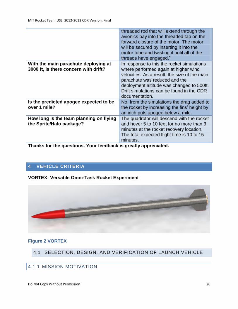
4 VEHICLE CRITERIA
VORTEX: Versatile Omni-Task Rocket Experiment
Figure 2 VORTEX
4.1 SELECTION, DESIGN, AND VERIFICATION OF LAUNCH VEHICLE
4.1.1 MISSION MOTIVATION
MIT Rocket Team USLI 2012-2013 CDR Version: Final
Do Not Copy Without Permission 27
When designing and building rockets, the team mainly focuses on rapid rocket body
construction, customization, reliability, and re-launch capabilities. With these attributes
in mind, the team is looking to improve the composite body/fin layup and motor
retention/avionics bay structure. Ultimately, a more robust, streamlined, and cost
effective design will be implemented for this year’s rocket.
4.1.2 MISSION STATEMENT
The MIT Rocket Team aims to develop a rocket which will successfully deploy a
quadrotor at the desired altitude in addition to meeting all USLI constraints/requirements
and serving as a device which will help the science payload to meet its mission
statement (noted below).
The MIT Rocket Team aims to develop an inexpensive and reusable rocket system in
order to rapidly deploy a quadrotor. The goals of the quadrotor design are to reduce
quadrotor ascent time and to test new methods of communication between mobile
targets. Using the quadrotor as a mobile platform, the team also intends to develop a
payload to study the cause of high altitude lightning discharges and their effect on the
surrounding environment, with the goal of validating existing mathematical models that
lack in situ data.
4.1.3 CONSTRAINTS
The vehicle and payload must follow all rules of NASA USLI 2012-2013, including but
not limited to:
Rocket apogee shall be closest to but not exceeding 5280ft.
At no time may a vehicle exceed 5600ft.
Must carry one NASA designated altimeter for official altitude record
Dual deployment recovery must be used
Dual altimeters must be used for all electronic flight systems.
Each altimeter must have its own battery and externally located arming switch.
Recovery and payload electronics must be independent from each other.
At all times the system must remain subsonic.
Shear pins must be used in the deployment of both the drogue and main
parachute.
All components of the system must land within 2500ft of the launch site in a wind
speed of 15 mi/hr.
MIT Rocket Team USLI 2012-2013 CDR Version: Final
Do Not Copy Without Permission 28
Each tethered section, of which there may be no more than 4 of, must land with
kinetic energy of less than 75 ft-lbf
Unmanned aerial vehicle (UAV) payloads of any type shall be tethered to the
vehicle with a remotely controlled release mechanism until the RSO has given
the authority to release the UAV.
Any payload element which is jettisoned during the recovery phase, or after the
launch vehicle lands, shall receive real-time RSO permission prior to initiating the
jettison event.
Scientific method must be used in the collection, analysis and reporting of all
data.
Electronic tracking devices must be used to transmit the location of all
components after landing.
Only commercially available, NAR/TRA certified motors may be used.
Full-scale flight model must be flown prior to FRR.
Students must do 100% of all work for USLI competition related projects
$5000 maximum value of rocket and science payload as it sits on the launch pad.
4.1.4 MISSION REQUIREMENTS
The mission requirements for the rocket and payload are as follows:
The VORTEX Rocket will meet the following objectives:
o Safely house quadrotor payload during launch and ascent
o Safely deliver the quadrotor payload to an altitude of 500ft during decent
The SPRITE Payload will meet the following objectives:
o Exhibit a controlled deployment from a descending rocket
o Safely house all hardware and electronics during all phases of the
mission: launch, normal operations, and recovery
o Relay telemetry and video to the ground station
o Relay telemetry to the nose cone via optical communication
o Track the nose cone and ground station
The HALO Payload will meet the following objectives:
o Ability to detect high altitude “lightning” events
o Gather atmospheric measurements of: the magnetic field, EMF radiation,
ULF/VLF waves, and the local electric field.
MIT Rocket Team USLI 2012-2013 CDR Version: Final
Do Not Copy Without Permission 29
o Gather atmospheric measurements of: pressure, temperature, relative
humidity, solar irradiance, and ultraviolet radiation at a frequency no less
than once every 5 seconds upon decent, and no less than once every
minute after landing.
o Take at least two still photographs during decent, and at least 3 after
landing.
o All pictures must be in an orientation such that the sky is at the top of the
frame.
o All data must be transmitted to ground station after completion of surface
operations.
4.1.5 SYSTEM REQUIREMENTS
The rocket and payload must meet a variety of requirements. Many of these
requirements are listed in section 3.3 Constraints, and duplicated in the NASA USLI
Request for Proposals starting on page 7. All of these program level requirements have
been met with our current vehicle design. Additionally, the program fully intends to imply
with all NAR, Tripoli and other requirements set out by various authorities having
jurisdiction (AHJ’s), such as the FAA, MIT EHS, MIT Association of Student Activities,
METRA launch rules, MDRA launch rules,
The system requirements for the rocket and payload are as follows:
System must be less than $5000 fair market value at time of flight
Rocket must reliably and accurately achieve apogee of 5280ft
Reliably deploy quadrotor at safe working altitude of 500ft
Stream telemetry, and video to ground station
Employ video and beacon tracking systems.
Quadrotor must have attitude control within 5 degrees of accuracy during normal
operations
Quadrotor must have basic altitude control with 6 feet (2 meters) of accuracy
during normal operations
Quadrotor must be able to hover for a minimum of ten minutes and operate for
45 minutes in a low power state (no power supplied to the propulsion system).
A further listing of payload, vehicle and program specific requirements are as follows:
The vehicle must recovery safely
MIT Rocket Team USLI 2012-2013 CDR Version: Final
Do Not Copy Without Permission 30
o This includes drogue and main parachute deployment systems must be
ground tested to ensure their reliability
o All sections must land with energy of less than 75ft-lbs.
The vehicle must be flight tested successfully prior to FRR
o This will require scheduling to allow multiple test opportunities to allow for
vehicle or recovery failure.
o This will require time commitments from members of the team to complete
the vehicle and payload in time to perform flight tests
4.1.6 MISSION SUCCESS CRITERIA
For the launch vehicle mission to be determined a success it must meet all of the launch
vehicle requirements/constraints set forth by the team, USLI officials, and USLI
regulations.
4.1.7 MILESTONES
The full schedule for rocket and payload development may be found in Timeline section
7.3. Key dates are presented below for reference.
9/29: Project initiation
10/29: PDR materials due
11/18: Scaled test launch
Nov and Dec: CDR payload design
1/14: CDR materials due
Dec, Jan, and Feb: Scale quadrotor testing and hardware manufacturing
Late Jan and Early Feb: Full-scale rocket manufacturing
Feb: Full-scale test launch
Early Mar: Payload verification testing
3/18: FRR materials due
Late March: Full-scale test launch
4/17: Travel to Huntsville
4/20: Competition launch
5/6: PLAR due
4.1.8 SYSTEM LEVEL DESIGN REVIEW
4.1.8.1 DRAWINGS AND SPECIFICATIONS
Vehicle mechanical drawings can be found in section 9.5.
MIT Rocket Team USLI 2012-2013 CDR Version: Final
Do Not Copy Without Permission 31
4.1.8.2 ANALYSIS AND MODEL RESULTS
Analysis of vehicle models can be found in section 4.1.8.2.
4.1.8.3 TEST DESCRIPTION AND RESULTS
A description of vehicle tests and results can be found in section 4.1.8.3.
4.1.8.4 FINAL MOTOR SELECTION
The final motor will be a Cesaroni L1115.
4.1.9 VERIFICATION PLAN
4.1.9.1 FUNCTIONAL REQUIREMENTS VERFICATION
Verification of the compliance with NASA 2012-2013 USLI handbook requirements and
the team’s set requirements will be completed as follows.
Table 4 Requirements and verification
Requirement Design Features that Meet this Requirement
Verification of Compliance
Rocket must reliably and accurately achieve apogee of 5280ft
The motor is sized so that apogee is 5280 ft.
To be verified after testing
At no time may a vehicle exceed 5600ft.
The motor is sized so that apogee is less than 5600 ft.
To be verified after testing
Must carry one NASA designated altimeter for official altitude record Dual deployment recovery must be used Dual altimeters must be used for all electronic flight systems.
A Perfectflite Straologger and Raven will be used for dual deployment and altitude determination.
Inspection
Each altimeter must have its own battery and externally located arming switch. Recovery and payload
The electronic schematics for the rocket and payload systems can be found in the respective rocket and payload avionics sections of this document. The
Inspection
MIT Rocket Team USLI 2012-2013 CDR Version: Final
Do Not Copy Without Permission 32
electronics must be independent from each other.
schematic show that these requirements are met.
At all times the system must remain subsonic.
An estimated velocity profile of rocket demonstrating subsonic flight can be found in the rocket propulsion/design section of this document.
Verified by simulation and full scaled launch.
Shear pins must be used in the deployment of both the drogue and main parachute.
Shear pins have be incorporated in the rocket design.
Inspection
All components of the system must land within 2500ft of the launch site in a wind speed of 15 mi/hr.
An estimated drift distance of components can be found in the rocket propulsion/design and recovery section of this document.
Simulation
Each tethered section, of which there may be no more than 4 of, must land with kinetic energy of less than 75 ft-lbf
As per design To be verified after testing
The vehicle must recovery safely
As per design To be verified after testing
Unmanned aerial vehicle (UAV) payloads of any type shall be tethered to the vehicle with a remotely controlled release mechanism until the RSO has given the authority to release the UAV.
The sabot will not open until RSO permission is given.
The quadrotor descends on chute until RSO permission
is given.
Verified by design
Any payload element which is jettisoned during the recovery phase, or after the launch vehicle lands, shall receive real-time RSO permission prior to initiating the jettison event.
Verified by design
Scientific method must be used in the collection,
As per design Consulting scientists
MIT Rocket Team USLI 2012-2013 CDR Version: Final
Do Not Copy Without Permission 33
analysis and reporting of all data.
Electronic tracking devices must be used to transmit the location of all components after landing.
As per design To be verified after testing
Only commercially available, NAR/TRA certified motors may be used.
As per design Verified by design
Full-scale flight model must be flown prior to FRR.
As per design Inspection
$5000 maximum value of rocket and science payload as it sits on the launch pad.
As per design Verified by design
Reliably deploy quadrotor at safe working altitude of 500ft
As per design To be verified after testing
4.1.9.2 APPROACH TO WORKMANSHIP
Through past experiences, the MIT Rocket Team has identified that the workmanship of
individual components plays an integral role in the final outcome of any project. With
this in mind, the team has set in place schedule of testing and teaching of the various
skills necessary for the fabrication and assembly of the rocket components.
Construction methods used by the team are learned from experienced sources, and all
methods are vetted through experienced personnel before being used. Team members
are taught basic fabrication methods under the instruction of more senior members, and
all components are inspected and tested as necessary before they are used.
Additionally, checklists are used during flight preparations to ensure that steps in the
preparation of the rocket are not missed.
4.1.9.3 STRUCTURAL COMPONENT TESTING
The team’s first priority will be to perform qualification testing on the structural
components of the rocket. The tests to be performed are as follows:
MIT Rocket Team USLI 2012-2013 CDR Version: Final
Do Not Copy Without Permission 34
• The body tube will be tested using a crush test in the axial direction and bending
test in the lateral direction. It will be tested with a variable mass, such as sand, to
determine the stiffness and failure force.
• A crush test will also be performed between two tubes to verify the strength of
the tube coupler.
• The bulkheads and their attachment to the body tube will be tested with a pull
test, in which the tube will be fixed and variable mass will be used to determine
pullout force.
• The fins will also be tested using a series of pull/push tests (also using a variable
mass and gravity) in order to test the fin strength in each of the 3 orthogonal
directions.
4.1.9.4 DEPLOYMENT TESTING
In addition to structural testing, several deployment and recovery tests will need to be
performed:
• Deployment altitude will be verified using barometric testing. The team has
constructed a small vacuum chamber, which is capable of roughly simulating
ambient pressure. As a result, the avionics package will be placed into the
vacuum chamber to ensure that it sends charge ignition commands at the right
times.
• In order to verify the failure force of the shear pins, a representative tube will be
used with a representative nose cone, with the open side of the tube covered.
The shear pins are mounted into the relevant brackets in flight orientation. The
black powder charge will be ignited at the closed end to validate the mass of
black powder to be used.
• Quadrotor deployment will also require testing, which can be performed in a
couple of phases: (1) the force of the drogue parachute on the sabot can be
simulated to ensure that the sabot separates from the tube and the quadrotor
deploys and (2) integrated deployment tests from a balloon platform. This test will
be described further in the payload testing section.
4.1.9.5 RECOVERY TESTING
Prior to the full scale test launch all recovery systems including altimeters, ejection
charges, and TenderDescenders will be tested to insure functionality at expected flight
MIT Rocket Team USLI 2012-2013 CDR Version: Final
Do Not Copy Without Permission 35
conditions. Ejection charge testing will take place in the team’s small vacuum chamber
to simulate low atmospheric pressures.
4.1.9.6 AVIONICS TESTING
A series of avionics tests will also be performed. A summary of the tests is provided
below. Greater detail can be found in the system testing section.
• The emergency locator beacons (transmitters and receiver) operation will be
checked, by searching for the beacons in a representative location.
• Each computer will also be checked to see if they downlink properly to the
ground station. This will be performed on the ground in a field and then on a
balloon platform using a representative ground station and rocket.
4.1.9.7 SCALED TEST LAUNCH
Finally, these tests will culminate in a representative scaled test launch, which will verify
functionality of all systems, including the quadrotor.
4.1.10 MANUFACTURING AND ASSEMBLY PLANS
To produce components of a high caliber the MIT Rocket Team has decided to use a
four-stage fabrication and assembly process. After the finalization of the designs, the
team moved straight into a fabrication-testing period where possible manufacturing
methods were evaluated for their feasibility. In this period the team decided on the
appropriate technique and materials needed for the fabrication of each component of
the flight vehicle. In this stage, fabrication methods were tested on representative
components sized to the approximate dimensions of the specified design. The testing
phase of production has been completed as of mid-January and the team has now
moved into the prototyping phase for the flight vehicle.
In the prototype phase, full-scale components will be constructed using the methods
determined during the testing phase of development. The resulting components will
then be assembled into a full-scale prototype with extra components being produced for
destructive testing methods. When the components are all fully tested, the any
components needing design changes will be refabricated to the new specifications and
a proto-flight model will be constructed.
The purpose of the proto-flight model is to allow for full-scale flight-testing procedures
with, and without the completed payload. It is expected that the proto-flight model will be
MIT Rocket Team USLI 2012-2013 CDR Version: Final
Do Not Copy Without Permission 36
completed in early February to allow for multiple launch attempts before the Flight
Readiness Review. Upon successful flight testing of the proto-flight vehicle, any
necessary design changes and repairs will be made to the airframe for the flight model
to be launched in Huntsville AL. Furthermore spare components will be manufactured to
the specifications of the flight model to mitigate the loss of components in transit to AL.
As stated above, the team is currently in the prototype phase of fabrication on track for
completion in early February. The team is purchasing all materials necessary to
construct a complete vehicle as well as a set of spare components. Construction is
currently underway and the components will be tested.
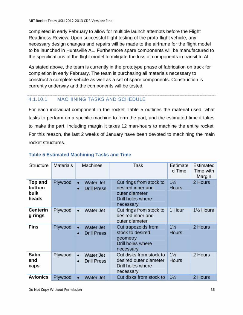
4.1.10.1 MACHINING TASKS AND SCHEDULE
For each individual component in the rocket Table 5 outlines the material used, what
tasks to perform on a specific machine to form the part, and the estimated time it takes
to make the part. Including margin it takes 12 man-hours to machine the entire rocket.
For this reason, the last 2 weeks of January have been devoted to machining the main
rocket structures.
Table 5 Estimated Machining Tasks and Time
Structure Materials Machines Task Estimated Time
Estimated Time with
Margin
Top and bottom bulk heads
Plywood Water Jet
Drill Press
Cut rings from stock to desired inner and outer diameter Drill holes where necessary
1½ Hours
2 Hours
Centering rings
Plywood Water Jet Cut rings from stock to desired inner and outer diameter
1 Hour 1½ Hours
Fins Plywood Water Jet
Drill Press
Cut trapezoids from stock to desired geometry Drill holes where necessary
1½ Hours
2 Hours
Sabo end caps
Plywood Water Jet
Drill Press
Cut disks from stock to desired outer diameter Drill holes where necessary
1½ Hours
2 Hours
Avionics Plywood Water Jet Cut disks from stock to 1½ 2 Hours
MIT Rocket Team USLI 2012-2013 CDR Version: Final
Do Not Copy Without Permission 37
bay top and bottom caps
Drill Press desired outer diameter Drill holes where necessary
Hours
Avionics bay panels
Plywood Vertical Band Saw
Cut rectangles from stock to desired geometry
1 Hour 1½ Hours
Body tube
Phenolic Horizontal Drill Press
Cut tubes from stock to desired length
½ Hour 1 Hour
4.1.11 DESIGN INTEGRITY
Design integrity is an important aspect to a project such as USLI. As such, the vehicle
has been designed using common design practices in high powered rocketry and has
also been influenced by the experience of the team.
4.1.11.1 SUITABLITY OF SHAPE AND FIN STYLE FOR MISSION
The fin style and shape in use was chosen due to its common use in rocketry. As a standard trapezoidal fin, it is easily modeled in RockSim. The fins are constructed of G10, a material commonly found in rockets of similar size. As was shown in the sub-scale test flight, the fins perform their objective of keeping the rocket flying straight.
4.1.11.2 PROPER USE OF MATERIALS
The structural elements in the vehicle are commonly used in high powered rocketry.
They include phenolic tubing wrapped in carbon fiber, fiberglass fins and a wood fin and
motor retention system. In previous MIT Rocket Team launches these structural
elements of the rocket performed their objectives. Verification will also be done through
analysis of the upcoming full scale test flight.
4.1.11.3 PROPER ASSEMBLY PROCEDURES
The design of the rocket dictates the assembly procedures. These procedures shall be
tested during the full scale test flight in order to determine their reliability and
functionality.
Structural components are self-aligning. Connects are made with fasteners are made.
Holes for such connections are not exactly rotationally symmetric, however, internal
markings allow for proper alignment.
MIT Rocket Team USLI 2012-2013 CDR Version: Final
Do Not Copy Without Permission 38
Load paths through the rocket are transferred into the rocket from the thrust ring on the
motor directly into the aft centering ring. From there, the motor mount tube, which is
glued to the aft centering ring, transfers load to the avionics bay. The aft centering ring
also transfers load to the airframe tube via the lip on the centering ring that extends to
the outer diameter (OD) of the tube. The airframe tube then transfers load to the
airframe coupler tube and all components above it.
All recovery loading is directed to the recovery eye-nut. This is connected by a piece of
threaded rod directly to the top of the motor case. From there, the load paths are similar
to that of the rocket under thrust.
4.1.11.4 MOTOR RENTENTION AND MOUNTING
Motor retention will be accomplished by a 3/8-16 threaded rod that will extend through
the avionics bay into the threaded tap on the forward closure of the motor. The motor
will be secured by inserting it into the motor tube and twisting it until all of the threads
have engaged.
4.1.11.5 DRAWINGS
Mechanical drawings can be found in section 9.5.
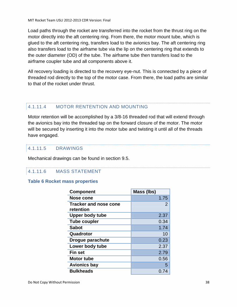
4.1.11.6 MASS STATEMENT
Table 6 Rocket mass properties
Component Mass (lbs)
Nose cone 1.75
Tracker and nose cone retention
2
Upper body tube 2.37
Tube coupler 0.34
Sabot 1.74
Quadrotor 10
Drogue parachute 0.23
Lower body tube 2.37
Fin set 2.79
Motor tube 0.56
Avionics bay 5
Bulkheads 0.74
MIT Rocket Team USLI 2012-2013 CDR Version: Final
Do Not Copy Without Permission 39
Motor 9.71
Main parachute 0.57
Mass Under Drogue 8.2
Mass Under Main 14.17
Support 6
Total Mass 46.17
4.1.11.7 SAFETY AND FAILURE ANALYSIS
4.1.11.7.1 RISKS, MITIGATION, AND FAILURE MODES
An overview of the risks, mitigations, and failure modes of the rocket can be found in the
Analysis of Failure Modes and Mitigations section of this document.
4.1.11.8 CHALLENGES AND SOLUTIONS
Table 7 Rocket challenges
Challenge Solutions
Requirement for the rocket to reach as close to 5,280 ft AGL as possible
Targeting a specific altitude is a difficult requirement, so it will be necessary to perform a great deal of modeling, which will include a RockSim model (that is validated against actual flight hardware mass/positioning data), an actual test launch for model verification, and potentially a custom validation model in MATLAB
Dependence on launch conditions for apogee
A flexible ballast will be used so that it is possible to tune the mass of the rocket on flight day
Deployment of the quadrotor in a "clean" manner
The quadrotor will be deployed with the drogue parachute active and using a sabot that will separate using the spring-loaded wings of the craft. A redundant deployment system may be used if deemed necessary. Furthermore, the quadrotor will be deployed under a recovery parachute. Separation of the vehicle and the parachute occurs after approval from the range officer has been attained.
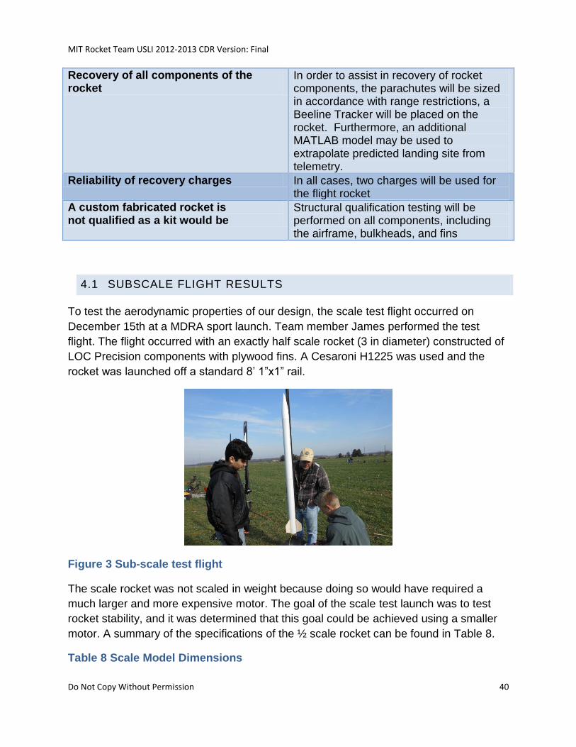
MIT Rocket Team USLI 2012-2013 CDR Version: Final
Do Not Copy Without Permission 40
Recovery of all components of the rocket
In order to assist in recovery of rocket components, the parachutes will be sized in accordance with range restrictions, a Beeline Tracker will be placed on the rocket. Furthermore, an additional MATLAB model may be used to extrapolate predicted landing site from telemetry.
Reliability of recovery charges In all cases, two charges will be used for the flight rocket
A custom fabricated rocket is not qualified as a kit would be
Structural qualification testing will be performed on all components, including the airframe, bulkheads, and fins
4.1 SUBSCALE FLIGHT RESULTS
To test the aerodynamic properties of our design, the scale test flight occurred on
December 15th at a MDRA sport launch. Team member James performed the test
flight. The flight occurred with an exactly half scale rocket (3 in diameter) constructed of
LOC Precision components with plywood fins. A Cesaroni H1225 was used and the
rocket was launched off a standard 8’ 1”x1” rail.
Figure 3 Sub-scale test flight
The scale rocket was not scaled in weight because doing so would have required a
much larger and more expensive motor. The goal of the scale test launch was to test
rocket stability, and it was determined that this goal could be achieved using a smaller
motor. A summary of the specifications of the ½ scale rocket can be found in Table 8.
Table 8 Scale Model Dimensions
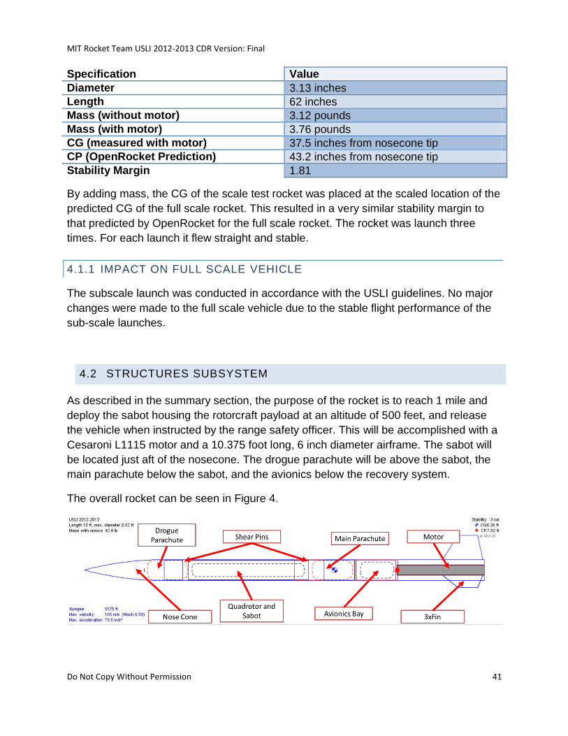
MIT Rocket Team USLI 2012-2013 CDR Version: Final
Do Not Copy Without Permission 41
Specification Value
Diameter 3.13 inches
Length 62 inches
Mass (without motor) 3.12 pounds
Mass (with motor) 3.76 pounds
CG (measured with motor) 37.5 inches from nosecone tip
CP (OpenRocket Prediction) 43.2 inches from nosecone tip
Stability Margin 1.81
By adding mass, the CG of the scale test rocket was placed at the scaled location of the
predicted CG of the full scale rocket. This resulted in a very similar stability margin to
that predicted by OpenRocket for the full scale rocket. The rocket was launch three
times. For each launch it flew straight and stable.
4.1.1 IMPACT ON FULL SCALE VEHICLE
The subscale launch was conducted in accordance with the USLI guidelines. No major
changes were made to the full scale vehicle due to the stable flight performance of the
sub-scale launches.
4.2 STRUCTURES SUBSYSTEM
As described in the summary section, the purpose of the rocket is to reach 1 mile and
deploy the sabot housing the rotorcraft payload at an altitude of 500 feet, and release
the vehicle when instructed by the range safety officer. This will be accomplished with a
Cesaroni L1115 motor and a 10.375 foot long, 6 inch diameter airframe. The sabot will
be located just aft of the nosecone. The drogue parachute will be above the sabot, the
main parachute below the sabot, and the avionics below the recovery system.
The overall rocket can be seen in Figure 4.
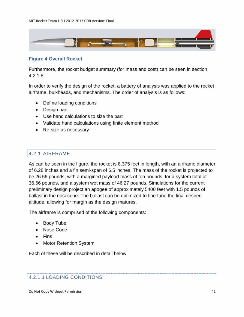
MIT Rocket Team USLI 2012-2013 CDR Version: Final
Do Not Copy Without Permission 42
Figure 4 Overall Rocket
Furthermore, the rocket budget summary (for mass and cost) can be seen in section
4.2.1.8.
In order to verify the design of the rocket, a battery of analysis was applied to the rocket
airframe, bulkheads, and mechanisms. The order of analysis is as follows:
Define loading conditions
Design part
Use hand calculations to size the part
Validate hand calculations using finite element method
Re-size as necessary
4.2.1 AIRFRAME
As can be seen in the figure, the rocket is 8.375 feet in length, with an airframe diameter
of 6.28 inches and a fin semi-span of 6.5 inches. The mass of the rocket is projected to
be 26.56 pounds, with a margined payload mass of ten pounds, for a system total of
36.56 pounds, and a system wet mass of 46.27 pounds. Simulations for the current
preliminary design project an apogee of approximately 5400 feet with 1.5 pounds of
ballast in the nosecone. The ballast can be optimized to fine tune the final desired
altitude, allowing for margin as the design matures.
The airframe is comprised of the following components:
Body Tube
Nose Cone
Fins
Motor Retention System
Each of these will be described in detail below.
4.2.1.1 LOADING CONDITIONS
MIT Rocket Team USLI 2012-2013 CDR Version: Final
Do Not Copy Without Permission 43
Determining loading conditions for a vehicle that must withstand a variety of largely
unknown dynamic and static loading is a difficult task. Furthermore, the rocket airframe
can be significantly overdesigned without applying too significant of a penalty to the
mass budget. As a result, the loading conditions were often estimated using significant
margin to account for uncertainty.
Launch Loading is summarized in Table 9.
Table 9 Launch Loading
Launch Loading
Aero Loading 90 lbf
Peak Thrust 385 Lbf
Payload Mass 15 Lbm
Max Acceleration 8 G
Total Axial 595 Lbf
MUF 1.5
Design Axial 892.5 Lbf
Total Lateral 150 Lbf
MUF 1.5
Design Lateral 225 Lbf
Aerodynamic loading is determined from the Rocksim model, peak thrust is determined
from the Cesaroni L1115 Thrust Curve, payload mass is determined from the quadrotor
design and sabot, and maximum acceleration is determined from the Rocksim model.
The maximum acceleration is found by dividing the peak thrust by the total estimated
rocket mass. The total axial force is the sum of the aerodynamic loading, peak thrust,
the product of the payload mass and the maximum acceleration. Although many of
these peak loads are applied independently from each other, to provide for a
conservative calculation, the loads are summed to create a total load, which is then
margined by a 1.5 model uncertainty factor, resulting in a design axial load of 890 lbf.
Lateral loading is determined by summing half of the aerodynamic and payload forces
and margining by a 1.5 model uncertainty factor. This is assumed to be highly margined
since as much as half of each of these loads is unlikely to be applied in the lateral
direction. Regardless, the design lateral load is therefore 225 lbf.
Recovery shock calculations are determined by examining the change in momentum of
the rocket due to deployment, as shown in Table 10
Table 10 Recovery Shock Calculations
Recovery Shock Calculations
MIT Rocket Team USLI 2012-2013 CDR Version: Final
Do Not Copy Without Permission 44
Initial Rate 64 Ft/s
Final Rate 18 Ft/s
G 32 Ft/s^2
T 0.1 S
Acceleration 460 Ft/s^2
Gs 14.375
Rocksim Gs 8
MUF 2
Design Gs 28.75
Design Force 431.25 Lbf
Recovery calculations show the descent rates of the system prior to deployment (under
the drogue) to be 64 ft/s and of the main rocket after deployment (under the main) to be
18 ft/s. Assuming a deployment time of 0.1s, this results in 14 Gs. Adding a model
uncertainty factor of 2 to this results in 29 Gs, which (given the mass of the payload
system) results in a design recovery shock force calculation of 430 lbf.
4.2.1.1.1 FINITE ELEMENT ANALYSIS
1. Motivation for finite element analysis:
In examining the effects of various aerial loads on the rocket body while in flight, we
decided that the methods of finite element analysis would prove useful. Finite element
methods are often used in structural analysis in order to make well informed, critical
design decisions.
2. Overview of Finite element equations
The basic premise of displacement-based finite element analysis is an extension of the
displacement method of beam and truss structural analysis. The general steps involved
in the analysis of these structures using the displacement based finite element method
are as follows1:
1. Idealize the structure as an assemblage of beam and truss elements that are
connected at structural joints.
MIT Rocket Team USLI 2012-2013 CDR Version: Final
Do Not Copy Without Permission 45
2. Identify the unknown joint displacements that completely define the displacement
response of the structural idealization.
3. Formulate the force balance equations corresponding to these unknown
displacements and solve these equations.
4. Calculate the internal element stress distributions based on the solution of the
displacements found in step (3) using the stress-strain law.
5. Interpret the solution of the structural idealization based on the assumptions made.
To summarize, the actual structural geometry will be divided up into elements, each with
several nodes that define compatibility of the element with the other elements in the
structure. The nodal displacements are found in each element by solving the linear
matrix equation:
where K represents the stiffness matrix, U represents the nodal displacements of each
element, and R represents the nodal forces that cause these displacements. The
displacements in three dimensions are:
The strains corresponding to these displacement are:
MIT Rocket Team USLI 2012-2013 CDR Version: Final
Do Not Copy Without Permission 46
Stresses corresponding to this material are given by the stress strain law, using the
elasticity matrix C:
The superscript T denotes the matrix transpose. The actual physical problem
can involve many different applied loads to the structure. A body can be subjected to
externally applied body forces (forces per unit volume), surface forces (forces per unit
area), and concentrated (point) loads. In order to lump all of these into the KU = R
formula above, we use the principle of virtual work:
The overbars represent a “virtual” strain and displacement, which is an arbitrarily
chosen continuous function independent from the actual physical displacement. The
“virtual” displacements can be considered as a thought experiment of sorts that allows
us to establish the virtual work principle. The left hand side of this equation represents
the internal virtual work, and the three terms on the right hand side represent, in order:
the effect on virtual work of applied body forces , applied surface forces and
concentrated loads , summed over all points The superscript implies that this is the
displacement to be evaluated on the particular surface of interest.
The final derivation necessary is the governing equations for each finite element.
Because this is an assemblage of discrete finite elements connected at nodal points, we
need a function to interpolate the nodal displacements across each element. Therefore
for each element m we have
MIT Rocket Team USLI 2012-2013 CDR Version: Final
Do Not Copy Without Permission 47
where is the displacement interpolation matrix, and the superscript denotes the element
m. is a vector of the displacements at each nodal point. From here we obtain the
strains,
where is the strain interpolation matrix. is found by appropriately differentiating the
elements of . This follows from the equations relating strain to displacement. Virtual
strains and displacements can be equated in the same manner as the real
displacements.
We now rewrite the principle of virtual work as a sum of integrations over all finite
elements:
and substitute the strains and displacements using the interpolation formulation
previously mentioned to obtain:
Again the superscript signifies evaluation of the matrix on the proper surface
coordinates. is a vector of concentrated nodal point forces with the same dimensions
as the nodal displacement vector , and the matrix is the element’s elasticity matrix.
From here we can construct the final matrix equation KU = R, using the following
integrals:
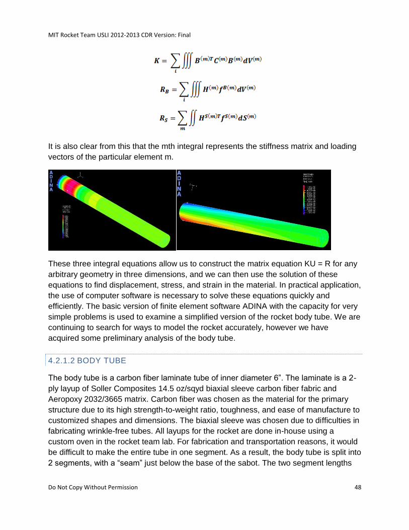
MIT Rocket Team USLI 2012-2013 CDR Version: Final
Do Not Copy Without Permission 48
It is also clear from this that the mth integral represents the stiffness matrix and loading
vectors of the particular element m.
These three integral equations allow us to construct the matrix equation KU = R for any
arbitrary geometry in three dimensions, and we can then use the solution of these
equations to find displacement, stress, and strain in the material. In practical application,
the use of computer software is necessary to solve these equations quickly and
efficiently. The basic version of finite element software ADINA with the capacity for very
simple problems is used to examine a simplified version of the rocket body tube. We are
continuing to search for ways to model the rocket accurately, however we have
acquired some preliminary analysis of the body tube.
4.2.1.2 BODY TUBE
The body tube is a carbon fiber laminate tube of inner diameter 6”. The laminate is a 2-
ply layup of Soller Composites 14.5 oz/sqyd biaxial sleeve carbon fiber fabric and
Aeropoxy 2032/3665 matrix. Carbon fiber was chosen as the material for the primary
structure due to its high strength-to-weight ratio, toughness, and ease of manufacture to
customized shapes and dimensions. The biaxial sleeve was chosen due to difficulties in
fabricating wrinkle-free tubes. All layups for the rocket are done in-house using a
custom oven in the rocket team lab. For fabrication and transportation reasons, it would
be difficult to make the entire tube in one segment. As a result, the body tube is split into
2 segments, with a “seam” just below the base of the sabot. The two segment lengths
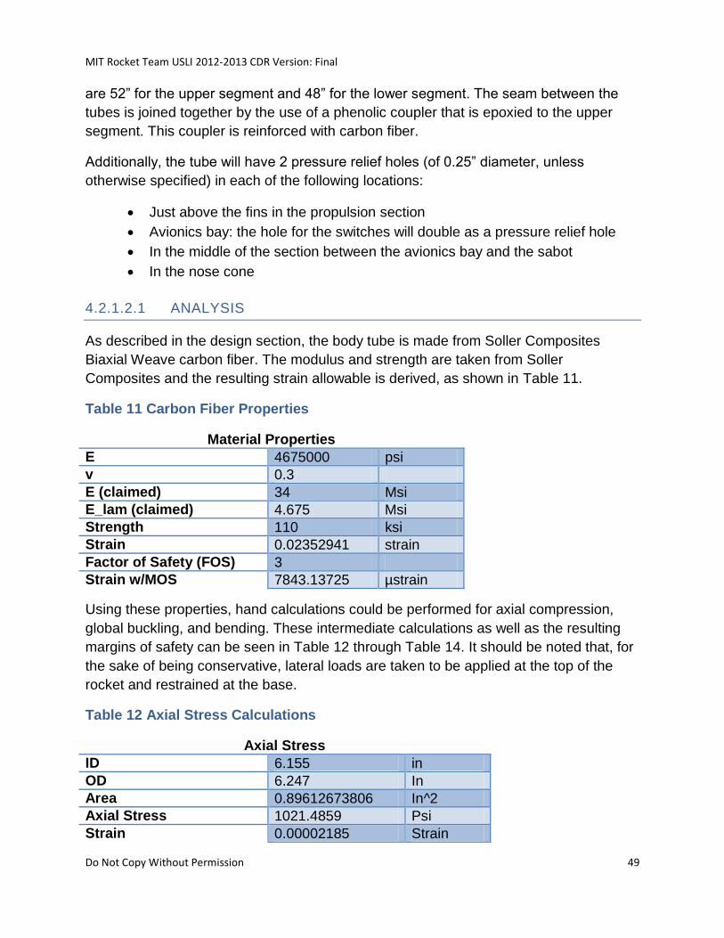
MIT Rocket Team USLI 2012-2013 CDR Version: Final
Do Not Copy Without Permission 49
are 52” for the upper segment and 48” for the lower segment. The seam between the
tubes is joined together by the use of a phenolic coupler that is epoxied to the upper
segment. This coupler is reinforced with carbon fiber.
Additionally, the tube will have 2 pressure relief holes (of 0.25” diameter, unless
otherwise specified) in each of the following locations:
Just above the fins in the propulsion section
Avionics bay: the hole for the switches will double as a pressure relief hole
In the middle of the section between the avionics bay and the sabot
In the nose cone
4.2.1.2.1 ANALYSIS
As described in the design section, the body tube is made from Soller Composites
Biaxial Weave carbon fiber. The modulus and strength are taken from Soller
Composites and the resulting strain allowable is derived, as shown in Table 11.
Table 11 Carbon Fiber Properties
Material Properties
E 4675000 psi
v 0.3
E (claimed) 34 Msi
E_lam (claimed) 4.675 Msi
Strength 110 ksi
Strain 0.02352941 strain
Factor of Safety (FOS) 3
Strain w/MOS 7843.13725 µstrain
Using these properties, hand calculations could be performed for axial compression,
global buckling, and bending. These intermediate calculations as well as the resulting
margins of safety can be seen in Table 12 through Table 14. It should be noted that, for
the sake of being conservative, lateral loads are taken to be applied at the top of the
rocket and restrained at the base.
Table 12 Axial Stress Calculations
Axial Stress
ID 6.155 in
OD 6.247 In
Area 0.89612673806 In^2
Axial Stress 1021.4859 Psi
Strain 0.00002185 Strain
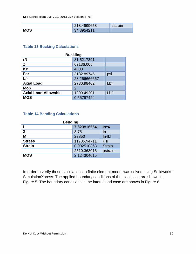
MIT Rocket Team USLI 2012-2013 CDR Version: Final
Do Not Copy Without Permission 50
218.4999658 µstrain
MOS 34.8954211
Table 13 Bucking Calculations
Buckling
r/t 81.5217391
Z 62136.005
Kc 4000
Fcr 3182.89745 psi
L/r 28.266666667
Axial Load 2780.98402 Lbf
MoS 2
Axial Load Allowable 1390.49201 Lbf
MOS 0.55797424
Table 14 Bending Calculations
Bending
I 7.620816554 In^4
Z 3.75 In
M 23850 In-lbf
Stress 11735.94711 Psi
Strain 0.002510363 Strain
2510.363018 µstrain
MOS 2.124304015
In order to verify these calculations, a finite element model was solved using Solidworks
SimulationXpress. The applied boundary conditions of the axial case are shown in
Figure 5. The boundary conditions in the lateral load case are shown in Figure 6.
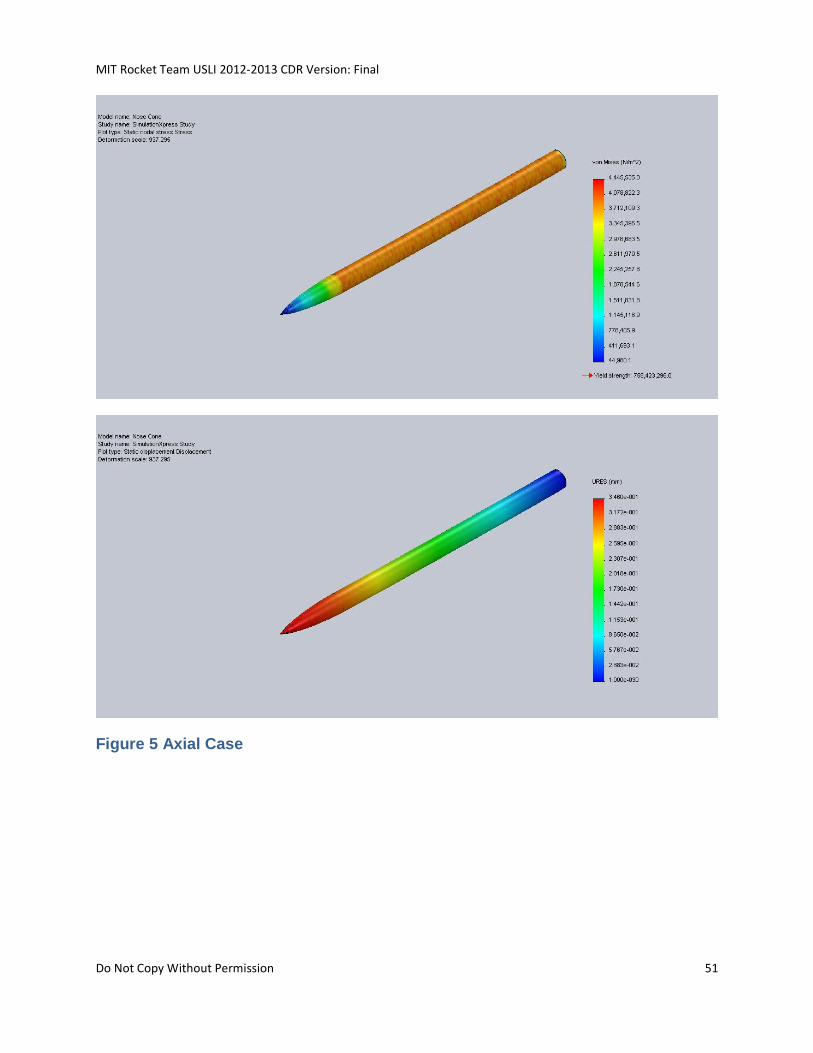
MIT Rocket Team USLI 2012-2013 CDR Version: Final
Do Not Copy Without Permission 51
Figure 5 Axial Case
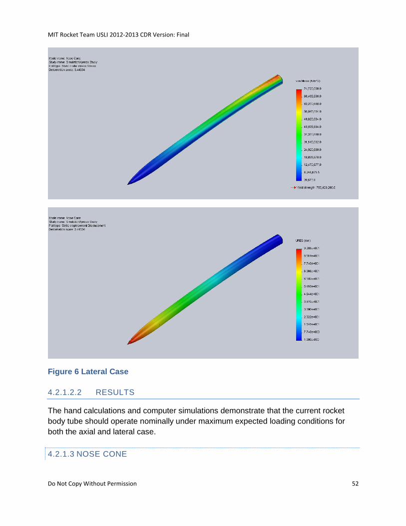
MIT Rocket Team USLI 2012-2013 CDR Version: Final
Do Not Copy Without Permission 52
Figure 6 Lateral Case
4.2.1.2.2 RESULTS
The hand calculations and computer simulations demonstrate that the current rocket
body tube should operate nominally under maximum expected loading conditions for
both the axial and lateral case.
4.2.1.3 NOSE CONE
MIT Rocket Team USLI 2012-2013 CDR Version: Final
Do Not Copy Without Permission 53
The nose cone is a commercial PML fiberglass nosecone. A piece of standard phenolic
tubing has been attached to the shoulder to allow the nosecone to fit properly in the
tube. A beeline tracker is also integrated into the bulkhead in the nosecone. The shape
is a tangent ogive and the length was chosen to fit the drogue parachute and maintain
stability of the rocket. The length is 27in.
The nose cone is mounted to the body tube using 4 nylon 2-56 bolts (MMC
97263A077), which will act as shear pins. Just like in the tube coupler above, shear
area is provided using doublers on both the top of the tube and the inner portion of the
nose cone. Similarly, the doublers are on the outside of the tube to allow the sabot to
cleanly exit the body tube. Bolts are used because they can be easily threaded into the
inner doubler during integration and will fail at low loading since they are plastic.
4.2.1.4 FINS
Three fins were chosen with the dimensions as shown to achieve rocket stability. The
fins are a carbon fiber, 3/16” FR4/G10, carbon fiber sandwich laminate to maximize
stiffness with minimum mass. The fins are located in position and angle relative to the
rocket using slots that are laser-cut into the motor centering rings. Oversized slits added
to the body tube to allow the fins to pass through, but provide no DOF restrictions.
Fabrication of the fins is as follows:
Laminate the FR4 core with a ply of carbon fiber on each face using standard
plate lamination techniques (see manufacturing plan section)
Obtain body tube with motor tube and centering rings installed
Affix fins to the centering rings using 5 minute epoxy and let cure
Apply another layer of carbon fiber across and between the fins, i.e. “Tip-to-Tip”
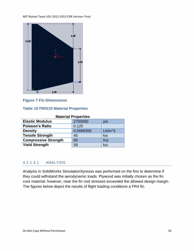
MIT Rocket Team USLI 2012-2013 CDR Version: Final
Do Not Copy Without Permission 54
Figure 7 Fin Dimensions
Table 15 FR/G10 Material Properties
Material Properties
Elastic Modulus 2700000 psi
Poisson’s Ratio 0.125
Density 0.0668355 Lb/in^3
Tensile Strength 45 ksi
Compressive Strength 60 Ksi
Yield Strength 58 ksi
4.2.1.4.1 ANALYSIS
Analysis in SolidWorks SimulaitonXpresss was performed on the fins to determine if
they could withstand the aerodynamic loads. Plywood was initially chosen as the fin
core material; however, near the fin root stresses exceeded the allowed design margin.
The figures below depict the results of flight loading conditions a FR4 fin.
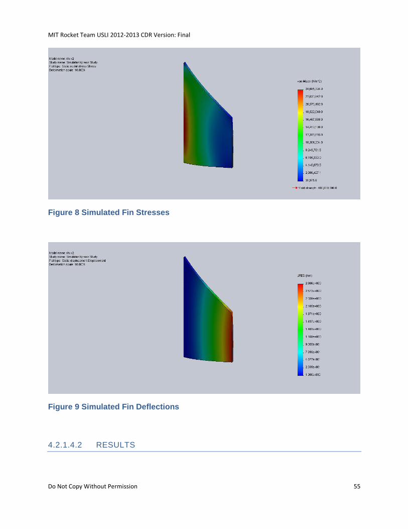
MIT Rocket Team USLI 2012-2013 CDR Version: Final
Do Not Copy Without Permission 55
Figure 8 Simulated Fin Stresses
Figure 9 Simulated Fin Deflections
4.2.1.4.2 RESULTS
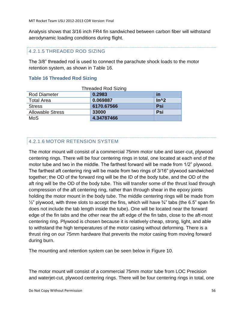
MIT Rocket Team USLI 2012-2013 CDR Version: Final
Do Not Copy Without Permission 56
Analysis shows that 3/16 inch FR4 fin sandwiched between carbon fiber will withstand
aerodynamic loading conditions during flight.
4.2.1.5 THREADED ROD SIZING
The 3/8” threaded rod is used to connect the parachute shock loads to the motor
retention system, as shown in Table 16.
Table 16 Threaded Rod Sizing
Threaded Rod Sizing
Rod Diameter 0.2983 in
Total Area 0.069887 In^2
Stress 6170.67566 Psi
Allowable Stress 33000 Psi
MoS 4.34787466
4.2.1.6 MOTOR RETENSION SYSTEM
The motor mount will consist of a commercial 75mm motor tube and laser-cut, plywood
centering rings. There will be four centering rings in total, one located at each end of the
motor tube and two in the middle. The farthest forward will be made from 1/2” plywood.
The farthest aft centering ring will be made from two rings of 3/16” plywood sandwiched
together; the OD of the forward ring will be the ID of the body tube, and the OD of the
aft ring will be the OD of the body tube. This will transfer some of the thrust load through
compression of the aft centering ring, rather than through shear in the epoxy joints
holding the motor mount in the body tube. The middle centering rings will be made from
½” plywood, with three slots to accept the fins, which will have ¾” tabs (the 6.5” span fin
does not include the tab length inside the tube). One will be located near the forward
edge of the fin tabs and the other near the aft edge of the fin tabs, close to the aft-most
centering ring. Plywood is chosen because it is relatively cheap, strong, light, and able
to withstand the high temperatures of the motor casing without deforming. There is a
thrust ring on our 75mm hardware that prevents the motor casing from moving forward
during burn.
The mounting and retention system can be seen below in Figure 10.
The motor mount will consist of a commercial 75mm motor tube from LOC Precision
and waterjet-cut, plywood centering rings. There will be four centering rings in total, one
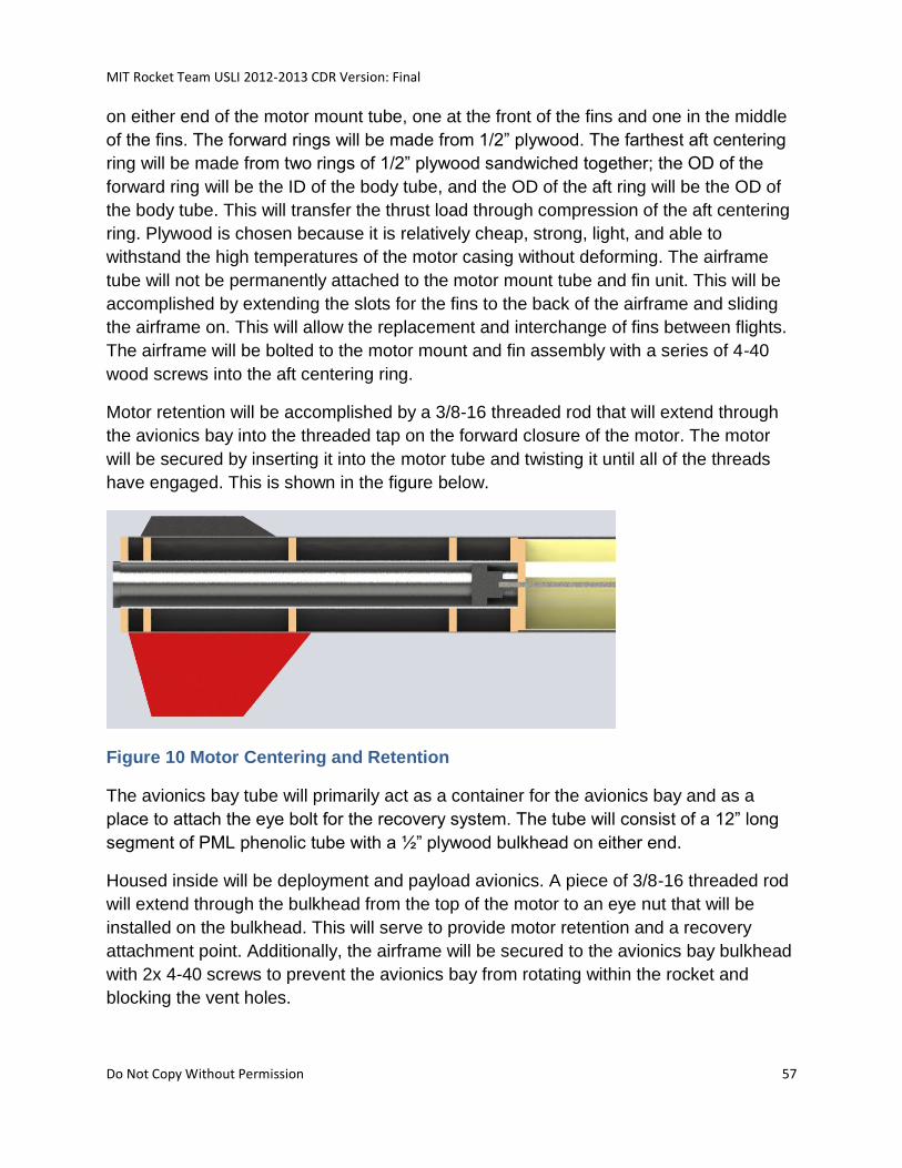
MIT Rocket Team USLI 2012-2013 CDR Version: Final
Do Not Copy Without Permission 57
on either end of the motor mount tube, one at the front of the fins and one in the middle
of the fins. The forward rings will be made from 1/2” plywood. The farthest aft centering
ring will be made from two rings of 1/2” plywood sandwiched together; the OD of the
forward ring will be the ID of the body tube, and the OD of the aft ring will be the OD of
the body tube. This will transfer the thrust load through compression of the aft centering
ring. Plywood is chosen because it is relatively cheap, strong, light, and able to
withstand the high temperatures of the motor casing without deforming. The airframe
tube will not be permanently attached to the motor mount tube and fin unit. This will be
accomplished by extending the slots for the fins to the back of the airframe and sliding
the airframe on. This will allow the replacement and interchange of fins between flights.
The airframe will be bolted to the motor mount and fin assembly with a series of 4-40
wood screws into the aft centering ring.
Motor retention will be accomplished by a 3/8-16 threaded rod that will extend through
the avionics bay into the threaded tap on the forward closure of the motor. The motor
will be secured by inserting it into the motor tube and twisting it until all of the threads
have engaged. This is shown in the figure below.
Figure 10 Motor Centering and Retention
The avionics bay tube will primarily act as a container for the avionics bay and as a
place to attach the eye bolt for the recovery system. The tube will consist of a 12” long
segment of PML phenolic tube with a ½” plywood bulkhead on either end.
Housed inside will be deployment and payload avionics. A piece of 3/8-16 threaded rod
will extend through the bulkhead from the top of the motor to an eye nut that will be
installed on the bulkhead. This will serve to provide motor retention and a recovery
attachment point. Additionally, the airframe will be secured to the avionics bay bulkhead
with 2x 4-40 screws to prevent the avionics bay from rotating within the rocket and
blocking the vent holes.
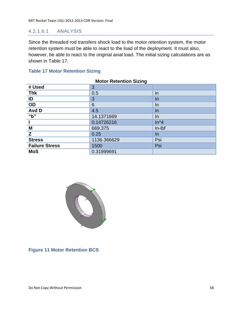
MIT Rocket Team USLI 2012-2013 CDR Version: Final
Do Not Copy Without Permission 58
4.2.1.6.1 ANALYSIS
Since the threaded rod transfers shock load to the motor retention system, the motor
retention system must be able to react to the load of the deployment. It must also,
however, be able to react to the original axial load. The initial sizing calculations are as
shown in Table 17.
Table 17 Motor Retention Sizing
Motor Retention Sizing
# Used 3
Thk 0.5 in
ID 3 In
OD 6 In
Avd D 4.5 In
“b” 14.1371669 In
I 0.14726216 In^4
M 669.375 In-lbf
Z 0.25 In
Stress 1136.366629 Psi
Failure Stress 1500 Psi
MoS 0.31999691
Figure 11 Motor Retention BCS
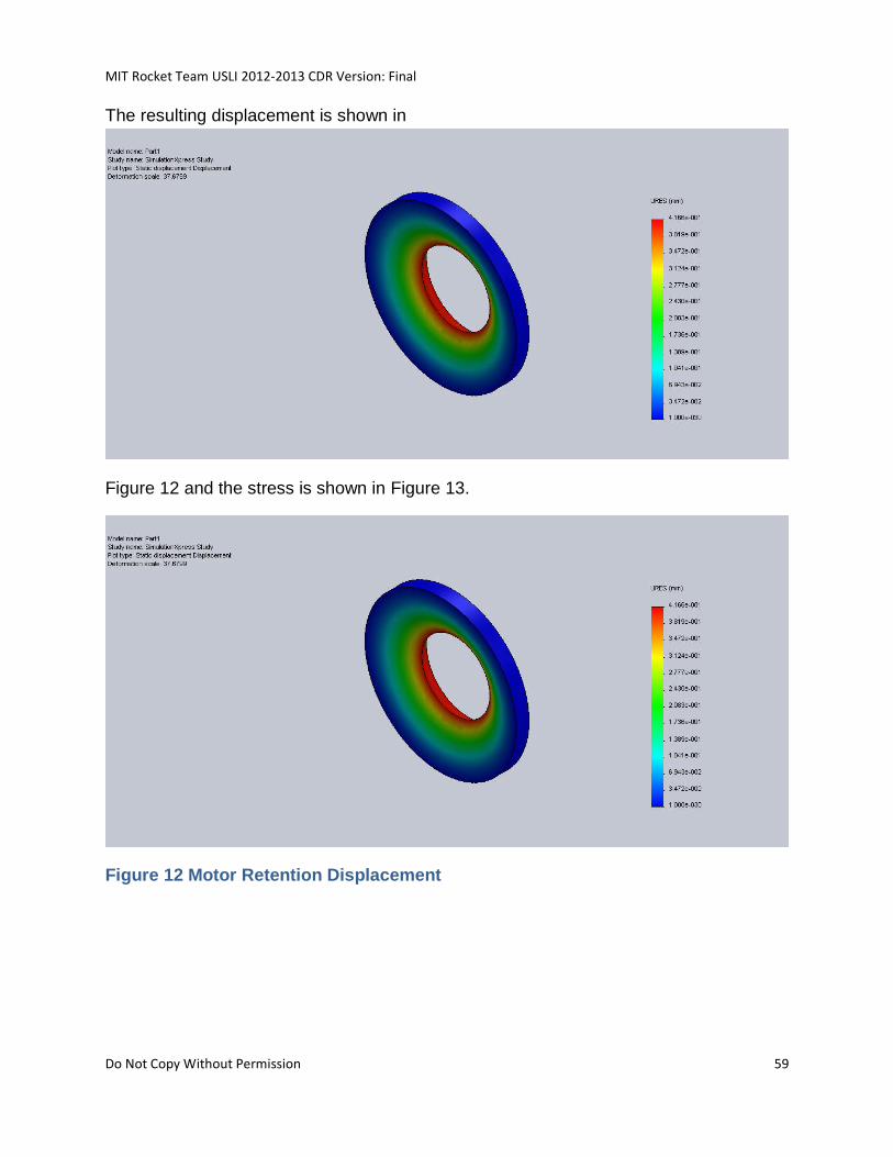
MIT Rocket Team USLI 2012-2013 CDR Version: Final
Do Not Copy Without Permission 59
The resulting displacement is shown in
Figure 12 and the stress is shown in Figure 13.
Figure 12 Motor Retention Displacement
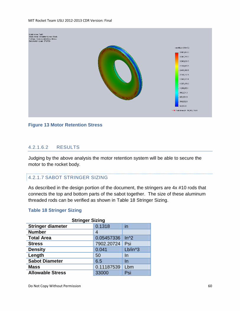
MIT Rocket Team USLI 2012-2013 CDR Version: Final
Do Not Copy Without Permission 60
Figure 13 Motor Retention Stress
4.2.1.6.2 RESULTS
Judging by the above analysis the motor retention system will be able to secure the
motor to the rocket body.
4.2.1.7 SABOT STRINGER SIZING
As described in the design portion of the document, the stringers are 4x #10 rods that
connects the top and bottom parts of the sabot together. The size of these aluminum
threaded rods can be verified as shown in Table 18 Stringer Sizing.
Table 18 Stringer Sizing
Stringer Sizing
Stringer diameter 0.1318 in
Number 4
Total Area 0.05457336 In^2
Stress 7902.20724 Psi
Density 0.041 Lb/in^3
Length 50 In
Sabot Diameter 6.5 In
Mass 0.11187539 Lbm
Allowable Stress 33000 Psi
MIT Rocket Team USLI 2012-2013 CDR Version: Final
Do Not Copy Without Permission 61
MoS 3.17604841
4.2.1.8 BUDGET SUMMARY
Table 19 Rocket Budget Summary
System Mass (kg) Cost (USD)
Propulsion 9.71 552.00
Airframe-Body 14.75 455.09
Avionics/Communications 5 347.38
Payload Support Equipment
2 152.24
Recovery 4.83 434.60
Subtotal 36.29 1941.31
4.3 PROPULSION SUBSYSTEM
The Rocket will be powered by a Cesaroni L1115 commercially available solid rocket
motor. This motor was chosen because it is commercially available and does not
require any modifications in order to reach the goal flight altitude of 5280 feet based off
preliminary mass estimates. This motor is more powerful than necessary based on
preliminary mass estimates, but this will ensure that even with potential mass creep as
the design of the rocket and payload matures, the rocket will be able to be optimized to
reach the target altitude with the addition of ballast.
The Cesaroni L1115 is 75mm in diameter, 24.5 inches in length, and has a total impulse
of 5015 Newton-seconds over a 4.49 second burn time.
For the full-scale test, the Cesaroni K661 solid rocket motor will be used. The CTI K661
has enough power to launch the full system up to an altitude of 1400 feet and has the
same diameter as the L1115, so minimal changes will need to be made to the launch
system for the full-scale test flight.
MIT Rocket Team USLI 2012-2013 CDR Version: Final
Do Not Copy Without Permission 62
The Cesaroni K661 is 75mm in diameter, 13.78 inches in length, and has a total
impulse of 2436 Newton-seconds over a 3.8 second burn time.
4.4 AVIONICS SUBSYSTEM
4.4.1 HARDWARE
4.4.1.1 FLIGHT COMPUTERS AND ALTIMETERS
Both the Raven2 and the Stratologger are programmed to deploy the drogue parachute
at apogee, while the main parachute is set to deploy after apogee is reached at an
altitude of 300 feet. This creates system redundancy in case one of the flight computers
fails.
Table 20 Hardware Specifications
Hardware Operating Voltage
Minimum Current
Dimensions
Mass
Altitude Accuracy
Operating Temperature
Maximum Altitude
Stratologger
4 – 16 Volts
1.5 milliamps
0.90”W, 2.75”L, 0.5”T
13 grams
+/- 1% -14C to 85C
100,000 feet
Raven2 1.3 – 20 Volts
N/A 0.80”W, 1.8”L, 0.55”T
8 grams
N/A -14C to 85C
N/A
4.4.1.1.1 STRATOLOGGER (PERFECTFLITE)
This flight computer measures the rocket’s altitude by sampling the surrounding air
pressure relative to the ground level pressure. The altitude above the launch platform is
calculated every 50 milliseconds. After launch, the device continuously collects data
until landing. Altitude readings are stored in nonvolatile memory and can be
downloaded to a computer through a serial data I/O connector. The Stratologger has
two channels for parachute deployment; one for the main parachute and the other for
drogue parachute. Figure 14 shows the Stratologger altimeter.
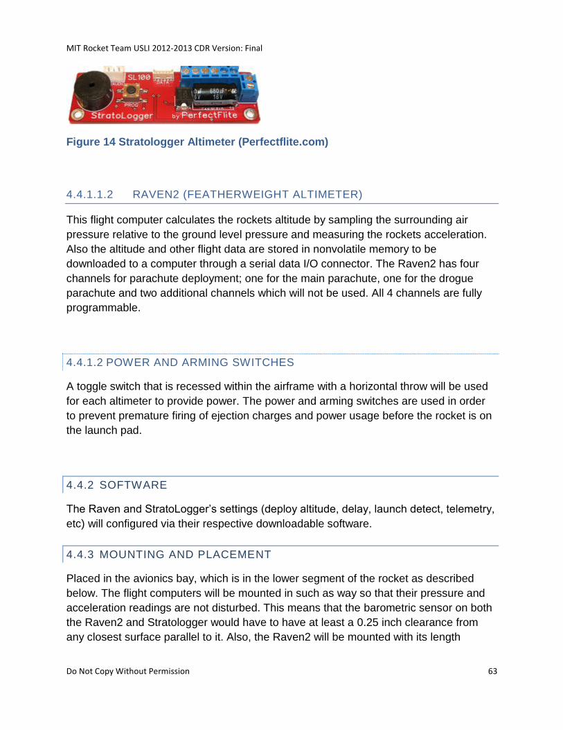
MIT Rocket Team USLI 2012-2013 CDR Version: Final
Do Not Copy Without Permission 63
Figure 14 Stratologger Altimeter (Perfectflite.com)
4.4.1.1.2 RAVEN2 (FEATHERWEIGHT ALTIMETER)
This flight computer calculates the rockets altitude by sampling the surrounding air
pressure relative to the ground level pressure and measuring the rockets acceleration.
Also the altitude and other flight data are stored in nonvolatile memory to be
downloaded to a computer through a serial data I/O connector. The Raven2 has four
channels for parachute deployment; one for the main parachute, one for the drogue
parachute and two additional channels which will not be used. All 4 channels are fully
programmable.
4.4.1.2 POWER AND ARMING SWITCHES
A toggle switch that is recessed within the airframe with a horizontal throw will be used
for each altimeter to provide power. The power and arming switches are used in order
to prevent premature firing of ejection charges and power usage before the rocket is on
the launch pad.
4.4.2 SOFTWARE
The Raven and StratoLogger’s settings (deploy altitude, delay, launch detect, telemetry,
etc) will configured via their respective downloadable software.
4.4.3 MOUNTING AND PLACEMENT
Placed in the avionics bay, which is in the lower segment of the rocket as described
below. The flight computers will be mounted in such as way so that their pressure and
acceleration readings are not disturbed. This means that the barometric sensor on both
the Raven2 and Stratologger would have to have at least a 0.25 inch clearance from
any closest surface parallel to it. Also, the Raven2 will be mounted with its length
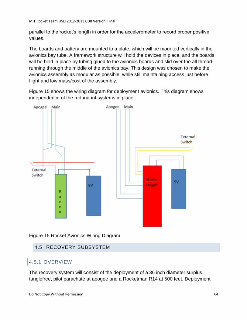
MIT Rocket Team USLI 2012-2013 CDR Version: Final
Do Not Copy Without Permission 64
parallel to the rocket’s length in order for the accelerometer to record proper positive
values.
The boards and battery are mounted to a plate, which will be mounted vertically in the
avionics bay tube. A framework structure will hold the devices in place, and the boards
will be held in place by tubing glued to the avionics boards and slid over the all thread
running through the middle of the avionics bay. This design was chosen to make the
avionics assembly as modular as possible, while still maintaining access just before
flight and low mass/cost of the assembly.
Figure 15 shows the wiring diagram for deployment avionics. This diagram shows
independence of the redundant systems in place.
Figure 15 Rocket Avionics Wiring Diagram
4.5 RECOVERY SUBSYSTEM
4.5.1 OVERVIEW
The recovery system will consist of the deployment of a 36 inch diameter surplus,
tanglefree, pilot parachute at apogee and a Rocketman R14 at 500 feet. Deployment
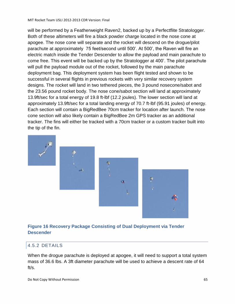
MIT Rocket Team USLI 2012-2013 CDR Version: Final
Do Not Copy Without Permission 65
will be performed by a Featherweight Raven2, backed up by a Perfectflite Stratologger.
Both of these altimeters will fire a black powder charge located in the nose cone at
apogee. The nose cone will separate and the rocket will descend on the drogue/pilot
parachute at approximately 75 feet/second until 500’. At 500’, the Raven will fire an
electric match inside the Tender Descender to allow the payload and main parachute to
come free. This event will be backed up by the Stratologger at 400’. The pilot parachute
will pull the payload module out of the rocket, followed by the main parachute
deployment bag. This deployment system has been flight tested and shown to be
successful in several flights in previous rockets with very similar recovery system
designs. The rocket will land in two tethered pieces, the 3 pound nosecone/sabot and
the 23.56 pound rocket body. The nose cone/sabot section will land at approximately
13.9ft/sec for a total energy of 19.8 ft-lbf (12.2 joules). The lower section will land at
approximately 13.9ft/sec for a total landing energy of 70.7 ft-lbf (95.91 joules) of energy.
Each section will contain a BigRedBee 70cm tracker for location after launch. The nose
cone section will also likely contain a BigRedBee 2m GPS tracker as an additional
tracker. The fins will either be tracked with a 70cm tracker or a custom tracker built into
the tip of the fin.
Figure 16 Recovery Package Consisting of Dual Deployment via Tender
Descender
4.5.2 DETAILS
When the drogue parachute is deployed at apogee, it will need to support a total system
mass of 36.6 lbs. A 3ft diameter parachute will be used to achieve a descent rate of 64
ft/s.
MIT Rocket Team USLI 2012-2013 CDR Version: Final
Do Not Copy Without Permission 66
Once an altitude of 500 ft AGL is reached, the tether securing the sabot inside the
rocket will release, allowing the drogue parachute to pull the sabot and the main
parachute out of the rocket. At this point, the rocket body will separate from the
sabot/nose/drogue section and free fall as the main parachute deploys. This will allow
for a considerable gap between the rocket body and the sabot, decreasing the risk of
the deployed quadrotor colliding with the rocket or becoming entangled in the main
parachute.
With the quadrotor deployed and the sabot separated from the rocket body, the
remaining structure has a mass of 23.6 lbs. With a 8ft diameter parachute, a final
descent rate of 19.8 ft/s can be achieved. Under the 3ft parachute, the nose cone and
sabot will have a final descent rate of 70.7 ft/s.
Table 21 Parachute Descent Rates
Final Descent Rate
System Under Drogue 70.7 ft/s
Nose/Sabot Final Descent Rate 69.7 ft/s
Rocket Body Under Main 19.8 ft/s
The drogue parachute and nose cone are directly connected to the sabot. This
assembly is initially connected to the recovery system retention threaded rod via the
Tender Descender.
The main parachute is also secured directly to the recovery system threaded rod (not by
the Tender Descender). Its deployment is constrained by the sabot.
The calculations for the amount of black powder required to successfully separate the
nose cone from the body tube can be found below.
The charge release mechanism will contain 0.2 grams of black powder. This number is
recommended by the manufacturer.
The drogue deployment charge must provide ample force to break the shear pins,
accelerate the nose cone away from the rocket body, and accelerate the drogue
parachute out of the nose cone. Four 2-56 nylon screws (MMC 94735A177) will be used
a shear pins to retain the nose cone. Nylon 6/6 has a shear strength of 10ksi.2 With
this, the maximum shear force can then be calculated by the following equation:
MIT Rocket Team USLI 2012-2013 CDR Version: Final
Do Not Copy Without Permission 67
where A is the cross-sectional area of the bolt, and τ is the shear strength. For a 2-56
screw, the minimum pitch diameter is 0.0717 in.3 This leads to a shear force of 40 lbf.
With four pins, the charge will have to provide a minimum force of 120 lbf. Adding 25%
margin, the charge will need to provide a total force of 150 lbf. This leads to a required
black powder mass of 2.1 g.
From previous testing, it was decided that a charge containing 3.5 grams of black
powder and two shear pins should be used. Also, previous testing of the Tender
Descender has confirmed that the manufacturer’s recommended charge size of 0.2
grams is sufficient to operate the device.
4.5.2.1 ELECTRICAL COMPONENTS
A Perfectflite Strattologger and a Featherweight Raven2 will be used to deploy the
drogue and main parachutes. The altimeters will be set up to deploy at the
barometrically detected apogee and at 300’ on the way down. They will be wired and
act completely independently such that a total failure of either altimeter or associated
wiring would not result in any ill-effects on the vehicle assuming the other altimeter
operated nominally. The electrical components, schematics and wiring diagrams are
further discussed near the end of the rocket Avionics/Communication section.
4.5.3 DEPLOYMENT
Deployment of the quadrotor, sabot, and parachutes is as follows.
Initially, the stacking of the rocket above the recovery system bulkhead is as follows (as
seen in Figure 17 and
Figure 18):
MIT Rocket Team USLI 2012-2013 CDR Version: Final
Do Not Copy Without Permission 68
• Payload Bulkhead attachment quick links
• Charge released locking mechanism
• Main parachute
• Sabot base hardpoint
• Sabot halves (cradling quadrotor)
• Sabot top hardpoint
• Drogue parachute quick link
• Drogue parachute
• Nose cone ejection charge
Note: There is a redundant igniter in the charge in the nose cone and a redundant
igniter in the charge released locking mechanism.
Figure 17 Sabot Overview
Figure 18 Payload Integration Stacking
The deployment then occurs as follows:
• Just after apogee, nose cone ejection charge fires
• Nose cone separates, but remains attached to the drogue parachute
• Drogue parachute deploys
• Rocket descends to 500 feet
MIT Rocket Team USLI 2012-2013 CDR Version: Final
Do Not Copy Without Permission 69
• At 500 feet, the charge released locking mechanism fires. Mechanism to be used
is the “FruityChutes L2 Tender Descender”
• The drogue parachute pulls the sabot out of the rocket tube
• As the sabot leaves the tube, the spring-loaded quadrotor arms push the sabot
halves apart
• The sabot pulls the main parachute bag out behind it
• Main parachute deploys and remains attached to the main body tube
After deployment, the rocket will fall to the ground in two sections, as shown in Figure
19:
• Sabot and nose cone, which are attached to the drogue parachute via the upper
hardpoint and a shock cord
• Main body tube, which is attached to the main parachute via the recovery system
bulkhead and a shock cord
Figure 19 Deployed Recovery Components
Deployment into two pieces (rather than one) is performed in order to minimize the
chance of contact between the sabot/quadrotor and the body tube after separation. This
will enable the drogue parachute to pull the quadrotor/sabot away from the rocket to
allow clean separation and minimize the chances of entanglement.
MIT Rocket Team USLI 2012-2013 CDR Version: Final
Do Not Copy Without Permission 70
As described above, the quadrotor is encased within the two sabot halves, which are
made of foam and laminated in a ply of fiberglass so as to maintain shape. Force will be
transferred between the hardpoints using a 4x 10-24 aluminum threaded rods, which
will mount to the upper and lower hardpoints using clearance holes and nuts. Finally,
plywood hardpoints are glued to the upper and lower ends of the sabot halves. These
hardpoints enable recovery and deployment system fixtures to be attached to the sabot.
One of these hardpoint sets is shown in Figure 20. As can be seen below, the hardpoint
halves overlap to ensure force transfer between halves when in tension. Adhesive is
applied as shown in the figure. An eye bolt is threaded into the lower hardpoint half,
which serves as the attachment points for:
• Lower hardpoint: the charge released locking mechanism
• Upper hardpoint: the drogue parachute and upper shock cord (attaches to nose
• cone)
It should be noted that the upper hardpoint will require eye bolts in both hard point
halves due to ensure both sabot halves remain attached to the drogue parachute.
Figure 20 Sabot Hard Point
4.5.4 TEST RESULTS
4.6 COMMUNICATIONS SUBSYSTEM
The rocket avionics system will not communicate telemetry to the ground stations
before, after, or during launch.
4.7 POWER SUBSYSTEM
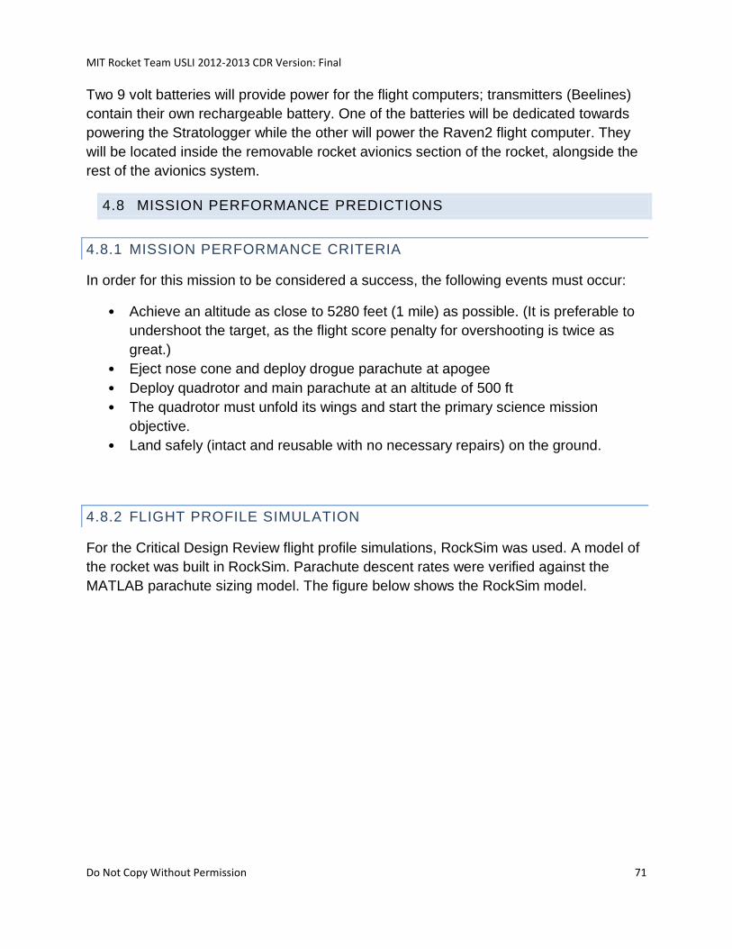
MIT Rocket Team USLI 2012-2013 CDR Version: Final
Do Not Copy Without Permission 71
Two 9 volt batteries will provide power for the flight computers; transmitters (Beelines)
contain their own rechargeable battery. One of the batteries will be dedicated towards
powering the Stratologger while the other will power the Raven2 flight computer. They
will be located inside the removable rocket avionics section of the rocket, alongside the
rest of the avionics system.
4.8 MISSION PERFORMANCE PREDICTIONS
4.8.1 MISSION PERFORMANCE CRITERIA
In order for this mission to be considered a success, the following events must occur:
• Achieve an altitude as close to 5280 feet (1 mile) as possible. (It is preferable to
undershoot the target, as the flight score penalty for overshooting is twice as
great.)
• Eject nose cone and deploy drogue parachute at apogee
• Deploy quadrotor and main parachute at an altitude of 500 ft
• The quadrotor must unfold its wings and start the primary science mission
objective.
• Land safely (intact and reusable with no necessary repairs) on the ground.
4.8.2 FLIGHT PROFILE SIMULATION
For the Critical Design Review flight profile simulations, RockSim was used. A model of
the rocket was built in RockSim. Parachute descent rates were verified against the
MATLAB parachute sizing model. The figure below shows the RockSim model.
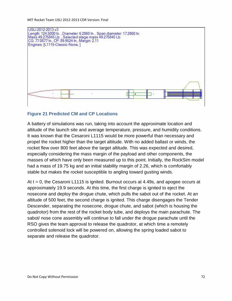
MIT Rocket Team USLI 2012-2013 CDR Version: Final
Do Not Copy Without Permission 72
Figure 21 Predicted CM and CP Locations
A battery of simulations was run, taking into account the approximate location and
altitude of the launch site and average temperature, pressure, and humidity conditions.
It was known that the Cesaroni L1115 would be more powerful than necessary and
propel the rocket higher than the target altitude. With no added ballast or winds, the
rocket flew over 800 feet above the target altitude. This was expected and desired,
especially considering the mass margin of the payload and other components, the
masses of which have only been measured up to this point. Initially, the RockSim model
had a mass of 19.75 kg and an initial stability margin of 2.26, which is comfortably
stable but makes the rocket susceptible to angling toward gusting winds.
At t = 0, the Cesaroni L1115 is ignited. Burnout occurs at 4.49s, and apogee occurs at
approximately 19.9 seconds. At this time, the first charge is ignited to eject the
nosecone and deploy the drogue chute, which pulls the sabot out of the rocket. At an
altitude of 500 feet, the second charge is ignited. This charge disengages the Tender
Descender, separating the nosecone, drogue chute, and sabot (which is housing the
quadrotor) from the rest of the rocket body tube, and deploys the main parachute. The
sabot/ nose cone assembly will continue to fall under the drogue parachute until the
RSO gives the team approval to release the quadrotor, at which time a remotely
controlled solenoid lock will be powered on, allowing the spring loaded sabot to
separate and release the quadrotor.
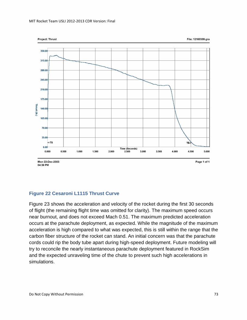
MIT Rocket Team USLI 2012-2013 CDR Version: Final
Do Not Copy Without Permission 73
Figure 22 Cesaroni L1115 Thrust Curve
Figure 23 shows the acceleration and velocity of the rocket during the first 30 seconds
of flight (the remaining flight time was omitted for clarity). The maximum speed occurs
near burnout, and does not exceed Mach 0.51. The maximum predicted acceleration
occurs at the parachute deployment, as expected. While the magnitude of the maximum
acceleration is high compared to what was expected, this is still within the range that the
carbon fiber structure of the rocket can stand. An initial concern was that the parachute
cords could rip the body tube apart during high-speed deployment. Future modeling will
try to reconcile the nearly instantaneous parachute deployment featured in RockSim
and the expected unraveling time of the chute to prevent such high accelerations in
simulations.
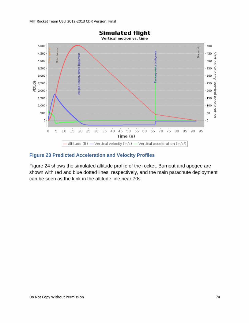
MIT Rocket Team USLI 2012-2013 CDR Version: Final
Do Not Copy Without Permission 74
Figure 23 Predicted Acceleration and Velocity Profiles
Figure 24 shows the simulated altitude profile of the rocket. Burnout and apogee are
shown with red and blue dotted lines, respectively, and the main parachute deployment
can be seen as the kink in the altitude line near 70s.
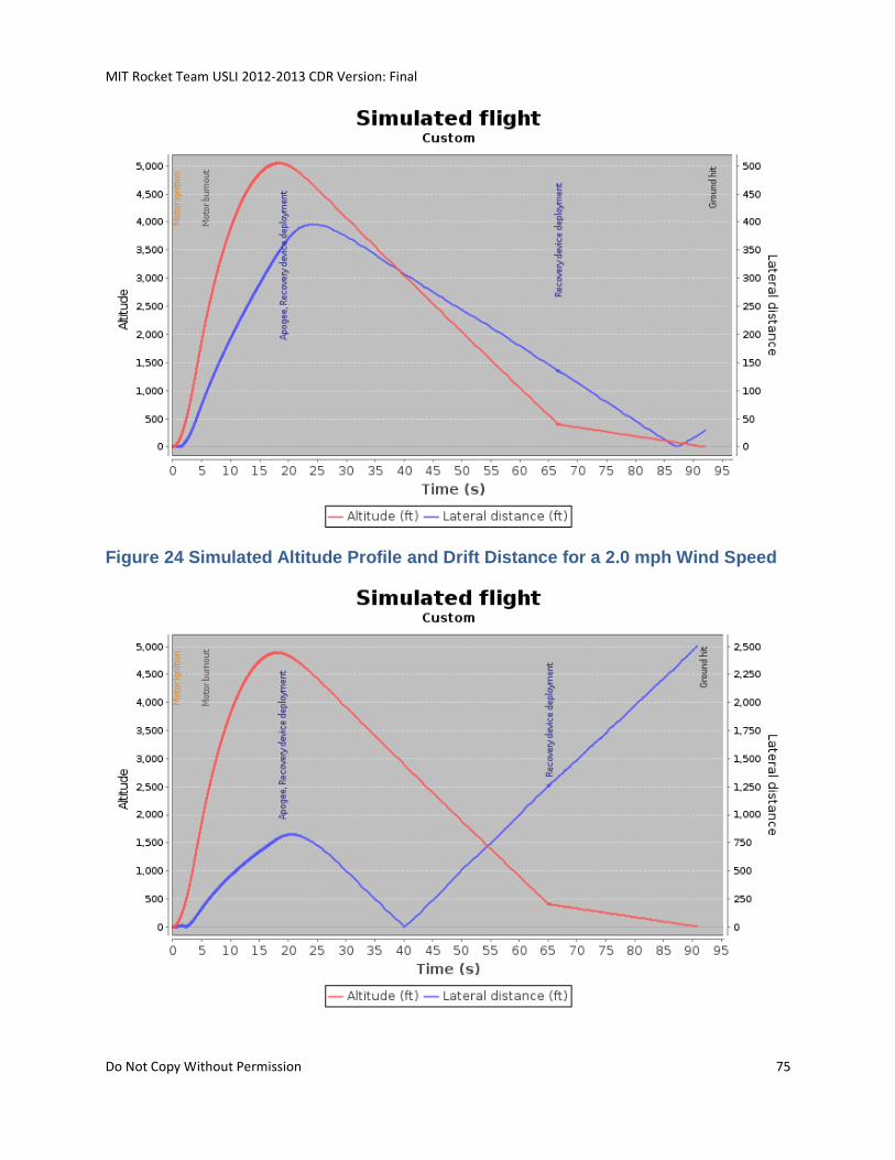
MIT Rocket Team USLI 2012-2013 CDR Version: Final
Do Not Copy Without Permission 75
Figure 24 Simulated Altitude Profile and Drift Distance for a 2.0 mph Wind Speed
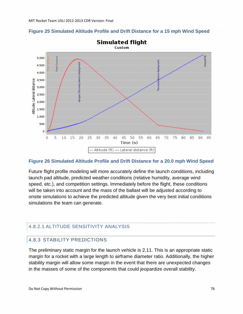
MIT Rocket Team USLI 2012-2013 CDR Version: Final
Do Not Copy Without Permission 76
Figure 25 Simulated Altitude Profile and Drift Distance for a 15 mph Wind Speed
Figure 26 Simulated Altitude Profile and Drift Distance for a 20.0 mph Wind Speed
Future flight profile modeling will more accurately define the launch conditions, including
launch pad altitude, predicted weather conditions (relative humidity, average wind
speed, etc.), and competition settings. Immediately before the flight, these conditions
will be taken into account and the mass of the ballast will be adjusted according to
onsite simulations to achieve the predicted altitude given the very best initial conditions
simulations the team can generate.
4.8.2.1 ALTITUDE SENSITIVITY ANALYSIS
4.8.3 STABILITY PREDICTIONS
The preliminary static margin for the launch vehicle is 2.11. This is an appropriate static
margin for a rocket with a large length to airframe diameter ratio. Additionally, the higher
stability margin will allow some margin in the event that there are unexpected changes
in the masses of some of the components that could jeopardize overall stability.
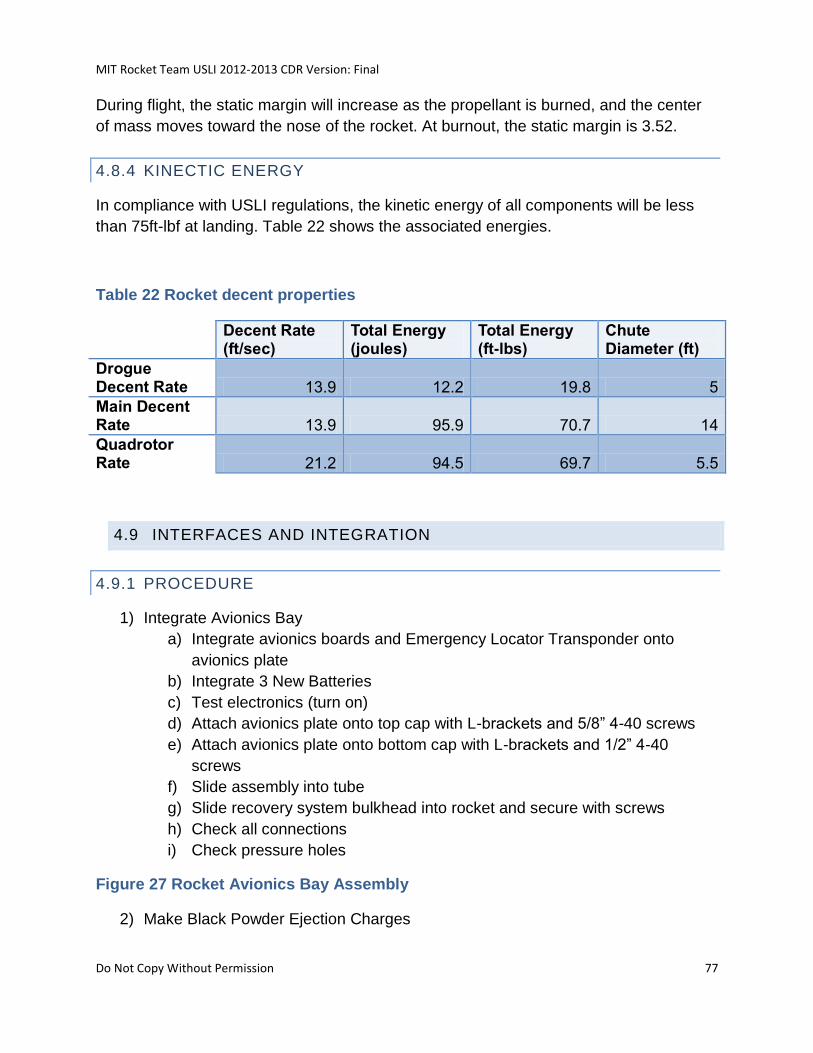
MIT Rocket Team USLI 2012-2013 CDR Version: Final
Do Not Copy Without Permission 77
During flight, the static margin will increase as the propellant is burned, and the center
of mass moves toward the nose of the rocket. At burnout, the static margin is 3.52.
4.8.4 KINECTIC ENERGY
In compliance with USLI regulations, the kinetic energy of all components will be less
than 75ft-lbf at landing. Table 22 shows the associated energies.
Table 22 Rocket decent properties
Decent Rate (ft/sec)
Total Energy (joules)
Total Energy (ft-lbs)
Chute Diameter (ft)
Drogue Decent Rate 13.9 12.2 19.8 5
Main Decent Rate 13.9 95.9 70.7 14
Quadrotor Rate 21.2 94.5 69.7 5.5
4.9 INTERFACES AND INTEGRATION
4.9.1 PROCEDURE
1) Integrate Avionics Bay
a) Integrate avionics boards and Emergency Locator Transponder onto
avionics plate
b) Integrate 3 New Batteries
c) Test electronics (turn on)
d) Attach avionics plate onto top cap with L-brackets and 5/8” 4-40 screws
e) Attach avionics plate onto bottom cap with L-brackets and 1/2” 4-40
screws
f) Slide assembly into tube
g) Slide recovery system bulkhead into rocket and secure with screws
h) Check all connections
i) Check pressure holes
Figure 27 Rocket Avionics Bay Assembly
2) Make Black Powder Ejection Charges
MIT Rocket Team USLI 2012-2013 CDR Version: Final
Do Not Copy Without Permission 78
a) Safety Officer will oversee this step
b) Connect to avionics
3) Recovery
a) Fold drogue parachute (use talcum powder)
b) Integrate drogue parachute and parachute protector
i. Attach to upper sabot hardpoint with quick link
c) If main parachute is not already properly folded in the parachute bag, fold
main parachute (use talcum powder)
d) Integrate main parachute and parachute protector (Figure 28)
i. Attach main shock cord to payload eye bolt with quick link
ii. Attach main parachute to shock cord with quick link
iii. Attach parachute bag to lower sabot hardpoint
e) Attach charge release locking mechanism to payload eye bolt
i. Connect leads to avionics
ii. Attach to lower sabot hardpoint
f) Nose Cone
i. Attach secondary shock cord between nose cone and sabot with
quick links
ii. Emergency Locator Transponder
g) Nose Cone, Drogue, and Sabot should not be attached to main shock
cord
h) Check all quick links (tighten with wrench)
Figure 28 Main Parachute/Shock Cord Attached to Eye Bolt and Recovery System
Bulkhead
4) Integrate rocket body with sabot/rotorcraft assembly a) Attach two rocket body segments together (Figure 28)
i. Thread four 6-32 ½’’ bolts through doublers b) Slide sabot (with rotorcraft) in routing the wires from the avionics assembly
through the raceway
Figure 29 Tube-Tube Interface
5) Integrate Nose Cone a) Slide into upper body tube (Figure 30)
Figure 30 Nose Cone/Upper Body Tube Interface
Figure 31 Integrated Avionics Assembly, Main Parachute, Sabot and Quadrotor
Assembly
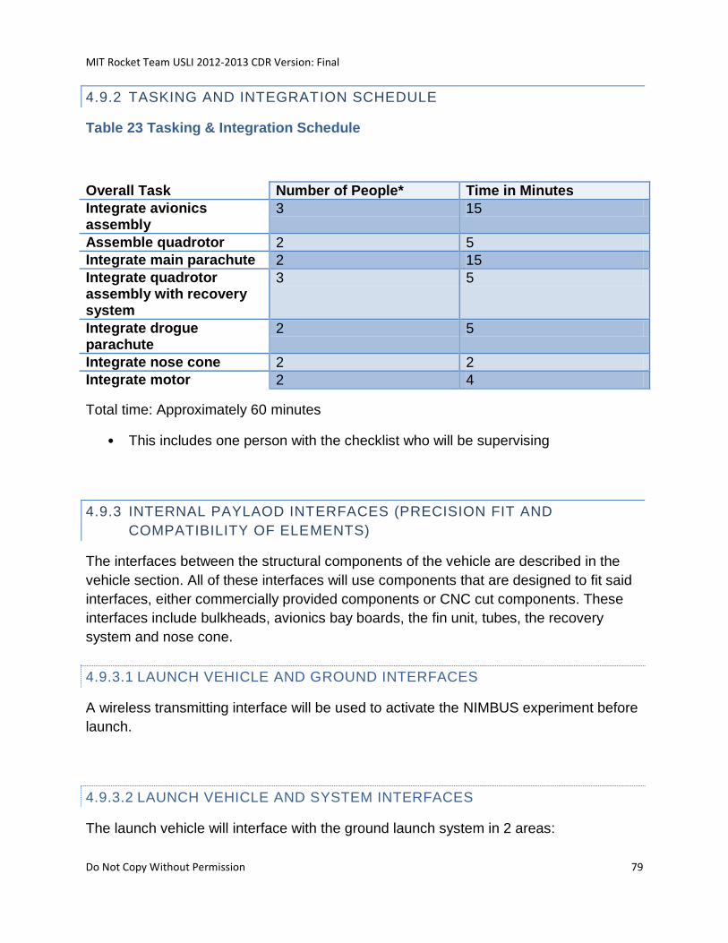
MIT Rocket Team USLI 2012-2013 CDR Version: Final
Do Not Copy Without Permission 79
4.9.2 TASKING AND INTEGRATION SCHEDULE
Table 23 Tasking & Integration Schedule
Overall Task Number of People* Time in Minutes
Integrate avionics assembly
3 15
Assemble quadrotor 2 5
Integrate main parachute 2 15
Integrate quadrotor assembly with recovery system
3 5
Integrate drogue parachute
2 5
Integrate nose cone 2 2
Integrate motor 2 4
Total time: Approximately 60 minutes
• This includes one person with the checklist who will be supervising
4.9.3 INTERNAL PAYLAOD INTERFACES (PRECISION FIT AND
COMPATIBILITY OF ELEMENTS)
The interfaces between the structural components of the vehicle are described in the
vehicle section. All of these interfaces will use components that are designed to fit said
interfaces, either commercially provided components or CNC cut components. These
interfaces include bulkheads, avionics bay boards, the fin unit, tubes, the recovery
system and nose cone.
4.9.3.1 LAUNCH VEHICLE AND GROUND INTERFACES
A wireless transmitting interface will be used to activate the NIMBUS experiment before
launch.
4.9.3.2 LAUNCH VEHICLE AND SYSTEM INTERFACES
The launch vehicle will interface with the ground launch system in 2 areas:
MIT Rocket Team USLI 2012-2013 CDR Version: Final
Do Not Copy Without Permission 80
• The launch pad. This will be accomplished with a pair of Delrin 1515 rail
buttons, one into the base of the rocket and located just below the avionics bay
• The alligator clips from the launch controller will be connected to the rocket
motor igniter
4.9.4 PAYLOAD INSTALLATION AND REMOVAL
4.9.5 SIMPLICITY OF INTEGRATION PROCEDURE
4.10 LAUNCH CONCERNS AND OPERATION PROCEDURES
4.10.1 SUMMARY OF ROCKET ASSEMBLY
4.10.2 LAUNCH SYSTEM AND PLATFORM
4.10.2.1 LAUNCH PAD
We will be using a Vaughn Brother’s Rocketry “High Power Launch Pad” with a 10ft
extruded aluminum T-slot rail.
Features:
• 200lb capacity
• Folds for easy transportation
• Holes in feet for staking the pad to the ground
• 12inch x 0.1inch thick steel blast deflector
• Accepts launch rods 1/4”- 3/4” and launch rails (with adapter)
4.10.2.2 CHECKLISTS AND STANDARD OPERATING PROCEDURES
4.10.2.2.1 CAUTION STATEMENT
Recall the Hazards Recognition Briefing. Always wear proper clothing and safety gear.
Always review procedures and relevant MSDS before commencing potentially
hazardous work. Always ask a knowledgeable member of the team if unsure about
equipment, tools, procedures, material handling, and/or other concerns. Be cognizant of
your and others’ actions. Keep work station as clutter-free as possible.
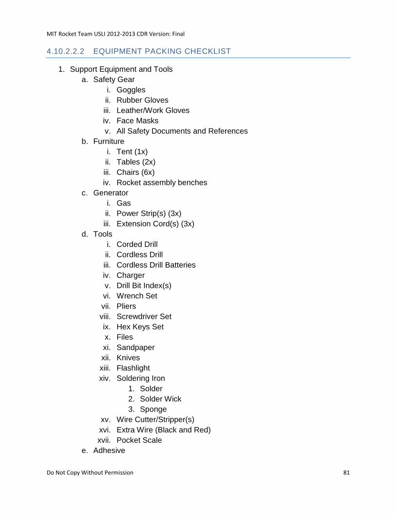
MIT Rocket Team USLI 2012-2013 CDR Version: Final
Do Not Copy Without Permission 81
4.10.2.2.2 EQUIPMENT PACKING CHECKLIST
1. Support Equipment and Tools
a. Safety Gear
i. Goggles
ii. Rubber Gloves
iii. Leather/Work Gloves
iv. Face Masks
v. All Safety Documents and References
b. Furniture
i. Tent (1x)
ii. Tables (2x)
iii. Chairs (6x)
iv. Rocket assembly benches
c. Generator
i. Gas
ii. Power Strip(s) (3x)
iii. Extension Cord(s) (3x)
d. Tools
i. Corded Drill
ii. Cordless Drill
iii. Cordless Drill Batteries
iv. Charger
v. Drill Bit Index(s)
vi. Wrench Set
vii. Pliers
viii. Screwdriver Set
ix. Hex Keys Set
x. Files
xi. Sandpaper
xii. Knives
xiii. Flashlight
xiv. Soldering Iron
1. Solder
2. Solder Wick
3. Sponge
xv. Wire Cutter/Stripper(s)
xvi. Extra Wire (Black and Red)
xvii. Pocket Scale
e. Adhesive
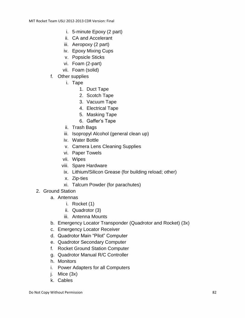
MIT Rocket Team USLI 2012-2013 CDR Version: Final
Do Not Copy Without Permission 82
i. 5-minute Epoxy (2 part)
ii. CA and Accelerant
iii. Aeropoxy (2 part)
iv. Epoxy Mixing Cups
v. Popsicle Sticks
vi. Foam (2-part)
vii. Foam (solid)
f. Other supplies
i. Tape
1. Duct Tape
2. Scotch Tape
3. Vacuum Tape
4. Electrical Tape
5. Masking Tape
6. Gaffer’s Tape
ii. Trash Bags
iii. Isopropyl Alcohol (general clean up)
iv. Water Bottle
v. Camera Lens Cleaning Supplies
vi. Paper Towels
vii. Wipes
viii. Spare Hardware
ix. Lithium/Silicon Grease (for building reload; other)
x. Zip-ties
xi. Talcum Powder (for parachutes)
2. Ground Station
a. Antennas
i. Rocket (1)
ii. Quadrotor (3)
iii. Antenna Mounts
b. Emergency Locator Transponder (Quadrotor and Rocket) (3x)
c. Emergency Locator Receiver
d. Quadrotor Main “Pilot” Computer
e. Quadrotor Secondary Computer
f. Rocket Ground Station Computer
g. Quadrotor Manual R/C Controller
h. Monitors
i. Power Adapters for all Computers
j. Mice (3x)
k. Cables
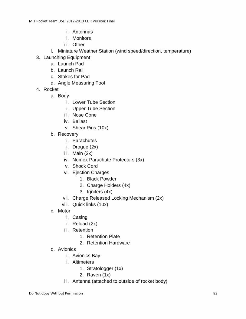
MIT Rocket Team USLI 2012-2013 CDR Version: Final
Do Not Copy Without Permission 83
i. Antennas
ii. Monitors
iii. Other
l. Miniature Weather Station (wind speed/direction, temperature)
3. Launching Equipment
a. Launch Pad
b. Launch Rail
c. Stakes for Pad
d. Angle Measuring Tool
4. Rocket
a. Body
i. Lower Tube Section
ii. Upper Tube Section
iii. Nose Cone
iv. Ballast
v. Shear Pins (10x)
b. Recovery
i. Parachutes
ii. Drogue (2x)
iii. Main (2x)
iv. Nomex Parachute Protectors (3x)
v. Shock Cord
vi. Ejection Charges
1. Black Powder
2. Charge Holders (4x)
3. Igniters (4x)
vii. Charge Released Locking Mechanism (2x)
viii. Quick links (10x)
c. Motor
i. Casing
ii. Reload (2x)
iii. Retention
1. Retention Plate
2. Retention Hardware
d. Avionics
i. Avionics Bay
ii. Altimeters
1. Stratologger (1x)
2. Raven (1x)
iii. Antenna (attached to outside of rocket body)
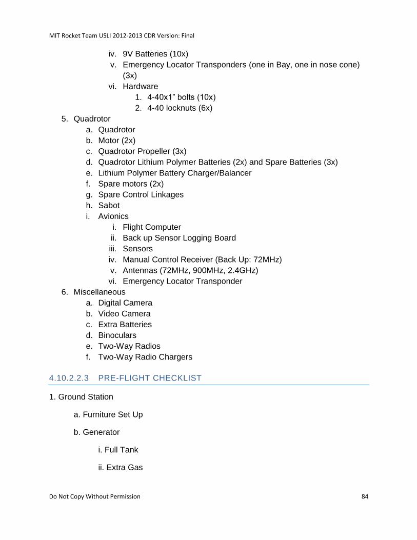
MIT Rocket Team USLI 2012-2013 CDR Version: Final
Do Not Copy Without Permission 84
iv. 9V Batteries (10x)
v. Emergency Locator Transponders (one in Bay, one in nose cone)
(3x)
vi. Hardware
1. 4-40x1” bolts (10x)
2. 4-40 locknuts (6x)
5. Quadrotor
a. Quadrotor
b. Motor (2x)
c. Quadrotor Propeller (3x)
d. Quadrotor Lithium Polymer Batteries (2x) and Spare Batteries (3x)
e. Lithium Polymer Battery Charger/Balancer
f. Spare motors (2x)
g. Spare Control Linkages
h. Sabot
i. Avionics
i. Flight Computer
ii. Back up Sensor Logging Board
iii. Sensors
iv. Manual Control Receiver (Back Up: 72MHz)
v. Antennas (72MHz, 900MHz, 2.4GHz)
vi. Emergency Locator Transponder
6. Miscellaneous
a. Digital Camera
b. Video Camera
c. Extra Batteries
d. Binoculars
e. Two-Way Radios
f. Two-Way Radio Chargers
4.10.2.2.3 PRE-FLIGHT CHECKLIST
1. Ground Station
a. Furniture Set Up
b. Generator
i. Full Tank
ii. Extra Gas
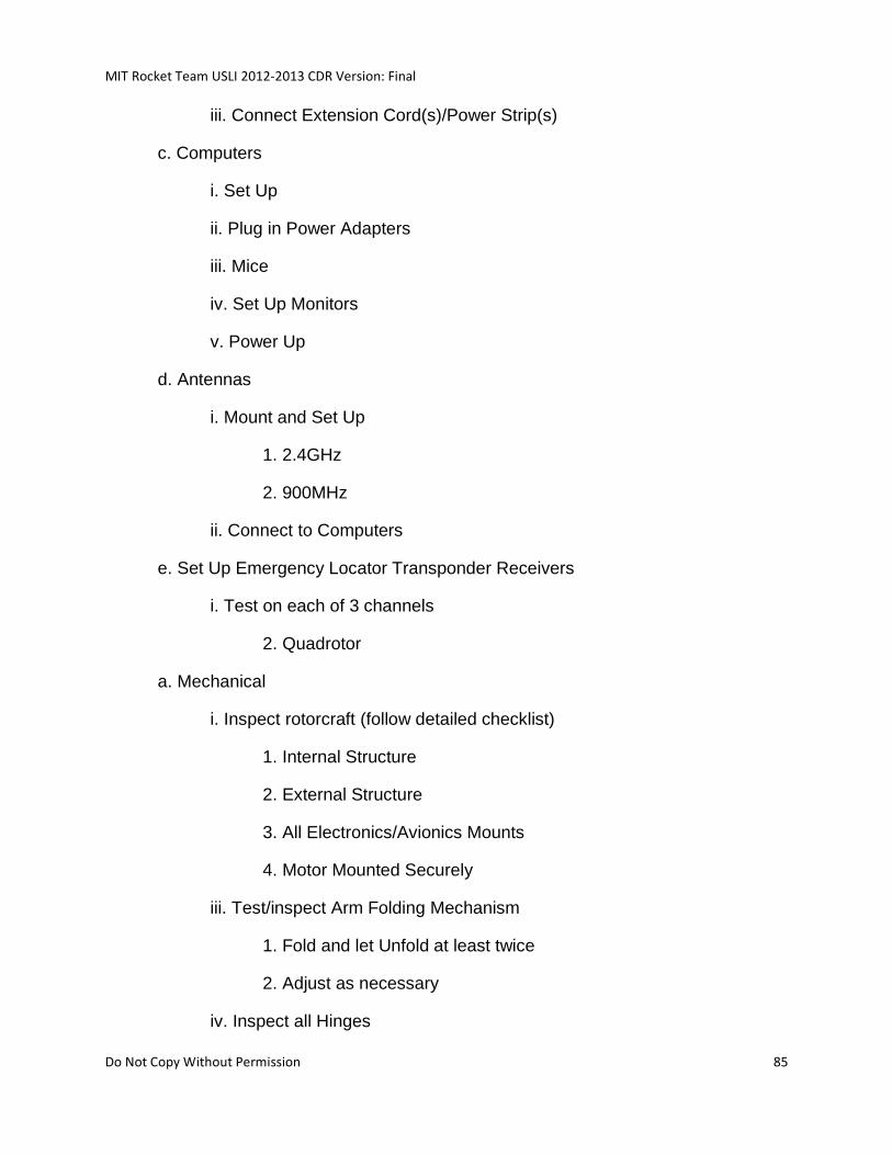
MIT Rocket Team USLI 2012-2013 CDR Version: Final
Do Not Copy Without Permission 85
iii. Connect Extension Cord(s)/Power Strip(s)
c. Computers
i. Set Up
ii. Plug in Power Adapters
iii. Mice
iv. Set Up Monitors
v. Power Up
d. Antennas
i. Mount and Set Up
1. 2.4GHz
2. 900MHz
ii. Connect to Computers
e. Set Up Emergency Locator Transponder Receivers
i. Test on each of 3 channels
2. Quadrotor
a. Mechanical
i. Inspect rotorcraft (follow detailed checklist)
1. Internal Structure
2. External Structure
3. All Electronics/Avionics Mounts
4. Motor Mounted Securely
iii. Test/inspect Arm Folding Mechanism
1. Fold and let Unfold at least twice
2. Adjust as necessary
iv. Inspect all Hinges
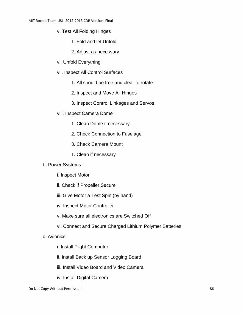
MIT Rocket Team USLI 2012-2013 CDR Version: Final
Do Not Copy Without Permission 86
v. Test All Folding Hinges
1. Fold and let Unfold
2. Adjust as necessary
vi. Unfold Everything
vii. Inspect All Control Surfaces
1. All should be free and clear to rotate
2. Inspect and Move All Hinges
3. Inspect Control Linkages and Servos
viii. Inspect Camera Dome
1. Clean Dome if necessary
2. Check Connection to Fuselage
3. Check Camera Mount
1. Clean if necessary
b. Power Systems
i. Inspect Motor
ii. Check if Propeller Secure
iii. Give Motor a Test Spin (by hand)
iv. Inspect Motor Controller
v. Make sure all electronics are Switched Off
vi. Connect and Secure Charged Lithium Polymer Batteries
c. Avionics
i. Install Flight Computer
ii. Install Back up Sensor Logging Board
iii. Install Video Board and Video Camera
iv. Install Digital Camera
MIT Rocket Team USLI 2012-2013 CDR Version: Final
Do Not Copy Without Permission 87
v. Install Manual Control 72MHz Receiver (Back Up)
vi. Inspect All Sensors
vii. Install Emergency Locator Transponder
viii. Connect Everything
d. Communication/Controls
i. All servos connected to proper channels
ii. All Avionics Connected
iii. Power On
v. Test Motor (using standard/manual R/C 72MHz transmitter)
1. Clear objects/people from the plane of the propeller
2. Throttle Up
3. Throttle Down
vi. Power Motor/Motor Controller Off
vii. Test Flight Computer
1. Communicating with Ground Station
viii. Test Data Feeds (turn quadrotor avionics on)
1. Temperature
2. Humidity
3. Solar Irradiation
4. UV Irradiation
5. Pressure
ix. Test IMU/GPS
1. Transmitting Telemetry
x. Test Autopilot (Make sure control responds correctly)
xi. Test Data Logging
MIT Rocket Team USLI 2012-2013 CDR Version: Final
Do Not Copy Without Permission 88
1. Digital Camera Still Shot Recorder
2. Back Up Sensor Data Logging
xii. Test Video Feed
1. Receiving Video
xiii. Test Emergency Locator Transponder
1. Receiving Emergency Locator Transponder signal
xiv. Power Up Motor/Motor Controller
xv. Flight Test with Manual R/C Control (no autopilot)
1. Receiving All Data
2. Proper Control Responses
xvi. Ground Test of Point-and-Click Control (with autopilot)
1. Receiving All Data
2. Proper Control Responses
xvii. Aerial Test of Point-and-Click Control
1. Trim control surfaces before flight
2. Back Up with Manual R/C Control
e. Switch out Lithium Polymer Batteries
f. Final Overall Inspection
g. Install rotor into Sabot
3. Rocket
a. Lay-out rocket sections in order
b. Check Body Antenna
c. Install Ballast into appropriate sections of sabot and body tube
d. Refer to Payload Integration Plan
i. Follow, then continue with this checklist
MIT Rocket Team USLI 2012-2013 CDR Version: Final
Do Not Copy Without Permission 89
e. Install all shear pins
f. Prepare Motor Reload
i. Safety Officer will oversee this step
g. Slide motor casing into rocket
h. Screw on motor retention
i. Make sure the tube-tube and tube-nose cone interfaces are secure
j. Inspect rail guides
k. Do a pre-launch briefing
4.10.2.2.4 LAUNCH CHECKLIST
1. Get approval from event administration to set up pad, ELS, and rocket
2. Set up pad
3. Tip pad over and install rail
4. Check all tube interfaces
5. Slide rocket onto rail down to stop
6. Tip up launch pad
7. Stake pad to ground
8. Arm Electronics
a. Listen for proper beeps
9. Put igniter into motor and secure it
10. Connect launch clips
11. Connect ELS to battery
12. Clear launch area/back up appropriate distance
13. Make sure Ground Station and Pilots are ready
MIT Rocket Team USLI 2012-2013 CDR Version: Final
Do Not Copy Without Permission 90
14. Get approval from event administration for launch
The following depend on procedures outlined by event administration:
15. Check to see if range and skies are clear
16. Insert key into ELS check continuity
17. Countdown from 5
18. Launch
19. Remove key from ELS
20. Disconnect ELS from battery
21. Recover Rocket and Quadrotor
4.10.3 RECOVERY PREPARATION
Using a short length of nylon webbing, attach the inside of the deployment bag to the
loop at the top of the main parachute.
Using a short length of nylon webbing, attach the inside of the deployment bag to the
loop at the top of the main parachute.
Next, fold the canopy width-wise so it can fit inside the deployment bag.
Fold the leader connecting the deployment bag and the parachute in a “figure 8” and
secure with a rubber band. Place inside deployment bag. Begin placing the canopy
inside the bag, folding it over itself in an Z pattern.
4.10.4 MOTOR PREPARATION
One of the team’s L2 members will supervise motor assembly. All fire hazards, e.g.
people smoking, lighters, potential ignition sources, will be removed from the immediate
surroundings during motor preparation.
See Appendix document for official and detailed Pro75 motor preparation instructions.
The assembled motor will be slid into the motor tube, and motor retention will be
screwed on.
MIT Rocket Team USLI 2012-2013 CDR Version: Final
Do Not Copy Without Permission 91
4.10.5 IGNITER INSTALLATION
Once the rocket is on the pad, tipped vertical, and all electronics are armed, the motor
igniter will be installed. Care will be taken to fully insert the igniter into the motor. The
igniter will be held in with tape and a 1/8” dowel, which will be easily pushed out when
the motor lights. Launch lead clips will be securely attached to the igniter leads at the
appropriate time.
4.10.6 LAUNCHER SETUP
The launcher will be assembled following the manufactures instructions by at least 3
team members.
4.10.7 SETUP ON LAUNCHER
Refer to Section 4.10.2.2.4 for Launch Checklist. After preparation is completed, the
rocket will be carefully carried out to the launch pad. The launch pad will be oriented
such that the rocket sits on the downwind side of the rail to avoid torque on the rail-
buttons. The launch rail will be tipped over to allow the rocket to be slid on horizontally.
Care will be taken when sliding the rail buttons into the rail slot. Then the rocket and rail
will be carefully tipped up to vertical.
Once the rocket is on the pad, tipped vertical, and all electronics are armed, the motor
igniter will be installed. Care will be taken to fully insert the igniter into the motor. The
igniter will be held in with tape and a 1/8” dowel, which will be easily pushed out when
the motor lights. Launch lead clips will be securely attached to the igniter leads at the
appropriate time.
4.10.8 TROUBLESHOOTING
Electronics will be disarmed any time the rocket is approached while on the pad. Table
24 summarizes possible problems and solutions with the rocket while it is on the pad.
Table 24 Possible Launch Failure Modes
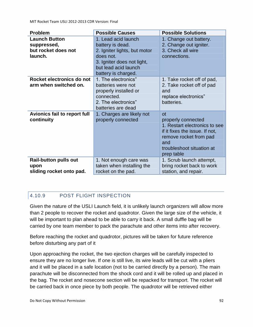
MIT Rocket Team USLI 2012-2013 CDR Version: Final
Do Not Copy Without Permission 92
Problem Possible Causes Possible Solutions
Launch Button suppressed, but rocket does not launch.
1. Lead acid launch battery is dead. 2. Igniter lights, but motor does not. 3. Igniter does not light, but lead acid launch battery is charged.
1. Change out battery. 2. Change out igniter. 3. Check all wire connections.
Rocket electronics do not arm when switched on.
1. The electronics‟ batteries were not properly installed or connected. 2. The electronics‟ batteries are dead
1. Take rocket off of pad, 2. Take rocket off of pad and replace electronics‟ batteries.
Avionics fail to report full continuity
1. Charges are likely not properly connected
ot properly connected 1. Restart electronics to see if it fixes the issue. If not, remove rocket from pad and troubleshoot situation at prep table
Rail-button pulls out upon sliding rocket onto pad.
1. Not enough care was taken when installing the rocket on the pad.
1. Scrub launch attempt, bring rocket back to work station, and repair.
4.10.9 POST FLIGHT INSPECTION
Given the nature of the USLI Launch field, it is unlikely launch organizers will allow more
than 2 people to recover the rocket and quadrotor. Given the large size of the vehicle, it
will be important to plan ahead to be able to carry it back. A small duffle bag will be
carried by one team member to pack the parachute and other items into after recovery.
Before reaching the rocket and quadrotor, pictures will be taken for future reference
before disturbing any part of it
Upon approaching the rocket, the two ejection charges will be carefully inspected to
ensure they are no longer live. If one is still live, its wire leads will be cut with a pliers
and it will be placed in a safe location (not to be carried directly by a person). The main
parachute will be disconnected from the shock cord and it will be rolled up and placed in
the bag. The rocket and nosecone section will be repacked for transport. The rocket will
be carried back in once piece by both people. The quadrotor will be retrieved either
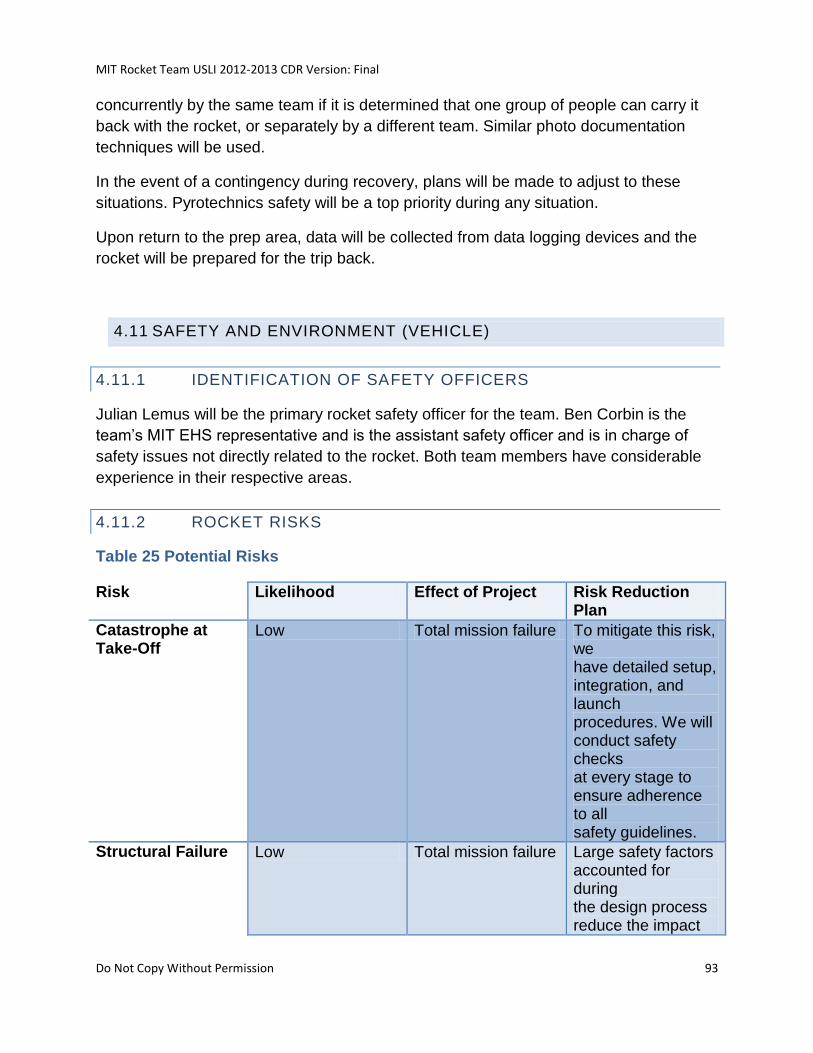
MIT Rocket Team USLI 2012-2013 CDR Version: Final
Do Not Copy Without Permission 93
concurrently by the same team if it is determined that one group of people can carry it
back with the rocket, or separately by a different team. Similar photo documentation
techniques will be used.
In the event of a contingency during recovery, plans will be made to adjust to these
situations. Pyrotechnics safety will be a top priority during any situation.
Upon return to the prep area, data will be collected from data logging devices and the
rocket will be prepared for the trip back.
4.11 SAFETY AND ENVIRONMENT (VEHICLE)
4.11.1 IDENTIFICATION OF SAFETY OFFICERS
Julian Lemus will be the primary rocket safety officer for the team. Ben Corbin is the
team’s MIT EHS representative and is the assistant safety officer and is in charge of
safety issues not directly related to the rocket. Both team members have considerable
experience in their respective areas.
4.11.2 ROCKET RISKS
Table 25 Potential Risks
Risk Likelihood Effect of Project Risk Reduction Plan
Catastrophe at Take-Off
Low Total mission failure To mitigate this risk, we have detailed setup, integration, and launch procedures. We will conduct safety checks at every stage to ensure adherence to all safety guidelines.
Structural Failure Low Total mission failure Large safety factors accounted for during the design process reduce the impact
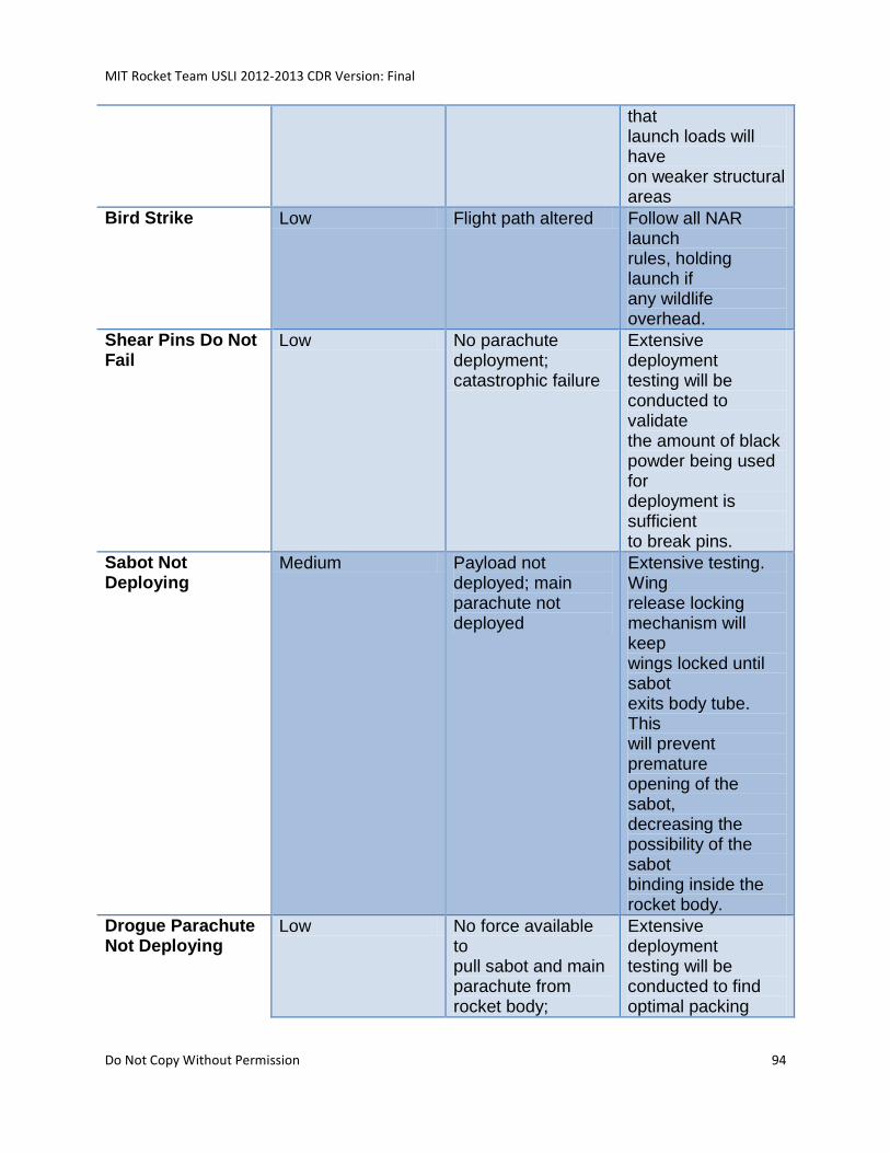
MIT Rocket Team USLI 2012-2013 CDR Version: Final
Do Not Copy Without Permission 94
that launch loads will have on weaker structural areas
Bird Strike Low Flight path altered Follow all NAR launch rules, holding launch if any wildlife overhead.
Shear Pins Do Not Fail
Low No parachute deployment; catastrophic failure
Extensive deployment testing will be conducted to validate the amount of black powder being used for deployment is sufficient to break pins.
Sabot Not Deploying
Medium Payload not deployed; main parachute not deployed
Extensive testing. Wing release locking mechanism will keep wings locked until sabot exits body tube. This will prevent premature opening of the sabot, decreasing the possibility of the sabot binding inside the rocket body.
Drogue Parachute Not Deploying
Low No force available to pull sabot and main parachute from rocket body;
Extensive deployment testing will be conducted to find optimal packing
MIT Rocket Team USLI 2012-2013 CDR Version: Final
Do Not Copy Without Permission 95
catastrophic failure method for drogue parachute.
Entanglement of Main Parachute
Medium Partial mission failure. Payload deployment still viable. Recovery of main rocket body unlikely
Parachute will be properly packed.
Failure of Recovery System Attachment Point
Medium Partial mission failure. Payload deployment still viable. Recovery of main rocket body unlikely
Ensure extensive testing of recovery system attachment points to ensure their ability to meet strength requirements
Sabot Fails to Separate After Ejection From Rocket
Low Rotorcraft unable to deploy; mission failure
Extensive testing to ensure wing rotator locking mechanism disengages after sabot exits rocket body, and 46 that spring force of deploying wings is sufficient to separate sabot halves.
Motor Fails to Ignite
Low Unable to launch; mission failure
Replace igniter
4.11.3 SAFETY ANALYSIS
4.11.4 ANALYSIS OF FAILURE MODES AND MITIGATIONS
The following table provides a preliminary analysis of the failure modes of the proposed
vehicle design, integration and launch operations.
Table 26 Potential Failure Modes
MIT Rocket Team USLI 2012-2013 CDR Version: Final
Do Not Copy Without Permission 96
Failure Mode Effects Precautions to prevent result
Precautions to prevent event
Motor Failure Property Damage, Injury
Stand up, follow path of rocket visually, move if needed. Follow proper launch safety distances
Store and assemble motor in accordance with manufacturer’s instructions
Recovery System Entanglement
Property Damage, Injury
Follow rocket‟s descent path visually, move if needed
Design and rigorously test recovery system in accordance with accepted HPR standards
Recovery System Structural Failure(bulkheads, shockcords, etc)
Property Damage, Injury
Follow rocket‟s descent path visually, move if needed
Perform pull tests on unrated components to ensure their strength. Components to be tested to 50g shock loads
Recovery System failure to deploy
Property Damage, Injury
Follow rocket‟s descent path visually, move if needed
Ensure rigorous testing of black powder charges, Tether release mechanisms and deployment altimeters and power supplies. Don‟t forget to arm altimeters
Recovery Device deployment on ground
Property Damage, Injury (especially eye)
Avoid placing body in path of parts if electronics are armed. Wear safety glasses if necessary.
Shunt charges until they are attached to recovery electronics. Do not move the rocket with armed electronics.
Unstable Vehicle Property Damage, Stand up, follow Ensure actual CG
MIT Rocket Team USLI 2012-2013 CDR Version: Final
Do Not Copy Without Permission 97
Injury rocket‟s path visually, move if needed. Confirm vehicle stability before launch.
position is acceptable relative to calculated CP
Brush Fire Fire damage, injury Have fire protection equipment and personnel trained in its use onsite
Follow NFPA table for dry brush around pad area.
Mid-Flight vehicle destruction (excessive forces on vehicle)
Loss of vehicle, Injury, Property damage
Follow rocket‟s path visually and move if needed if vehicle does come apart
Design, construct and test vehicle to assure successful flight. Use standard construction procedures for LII-LIII rockets, including sufficient bulkheads, fins, motor retention and couplers.
Failure of quadrotor to deploy
Loss of science value, potential failure of main recovery device
Visually track vehicle & quadrotor, and move if needed
Rigorously test quadrotor deployment method as an integrated component in the rocket recovery system. Ensure all other aspects of the rocket flight succeed
Failure to successfully integrate vehicle in allotted 4 hour time period
Loss of launch opportunity
N/A Practice integration techniques under time constrains to ensure they are achievable in allotted time.
Failure of vehicle to reach desired altitude
Loss of competition points and potential loss of science value
N/A Use multiple simulation programs and data from actual
MIT Rocket Team USLI 2012-2013 CDR Version: Final
Do Not Copy Without Permission 98
flight tests to fine tune rocket mass and motor selection
Quadrotor Scientific data is unrecoverable
Loss of science value
N/A Perform range communication tests with all flight hardware in flight configuration. Allow electronics to be quickly reconfigurable in case of frequency conflicts.
4.11.5 PERSONAL HAZARDS
A listing of personnel hazards and evidence of understanding of safety hazards is
provided in the sections below.
4.11.5.1 SAFETY CHECKLIST
In order to assure a safe and successful flight, a checklist must be followed during prep
activities and launch. In order to reduce personnel hazards during the prep of the
vehicle before taking it to the pad, the following precautions must be taken.
• Always wear safety glasses when dealing with rocket parts containing small
hardware or pyrotechnic charges.
• Never look down a tube with live pyrotechnic charges in it.
• Always point rocket and pyrotechnic charges away from body and other people
• Avoid carrying devices that have live electrical contacts (radios, cell phones, etc.)
while prepping live pyrotechnic charges.
• Never arm electronics when rocket isn’t on pad unless the area has been cleared
and everyone knows that pyrotechnic continuity checks are being done.
• Always follow the NAR/TRA safety codes.
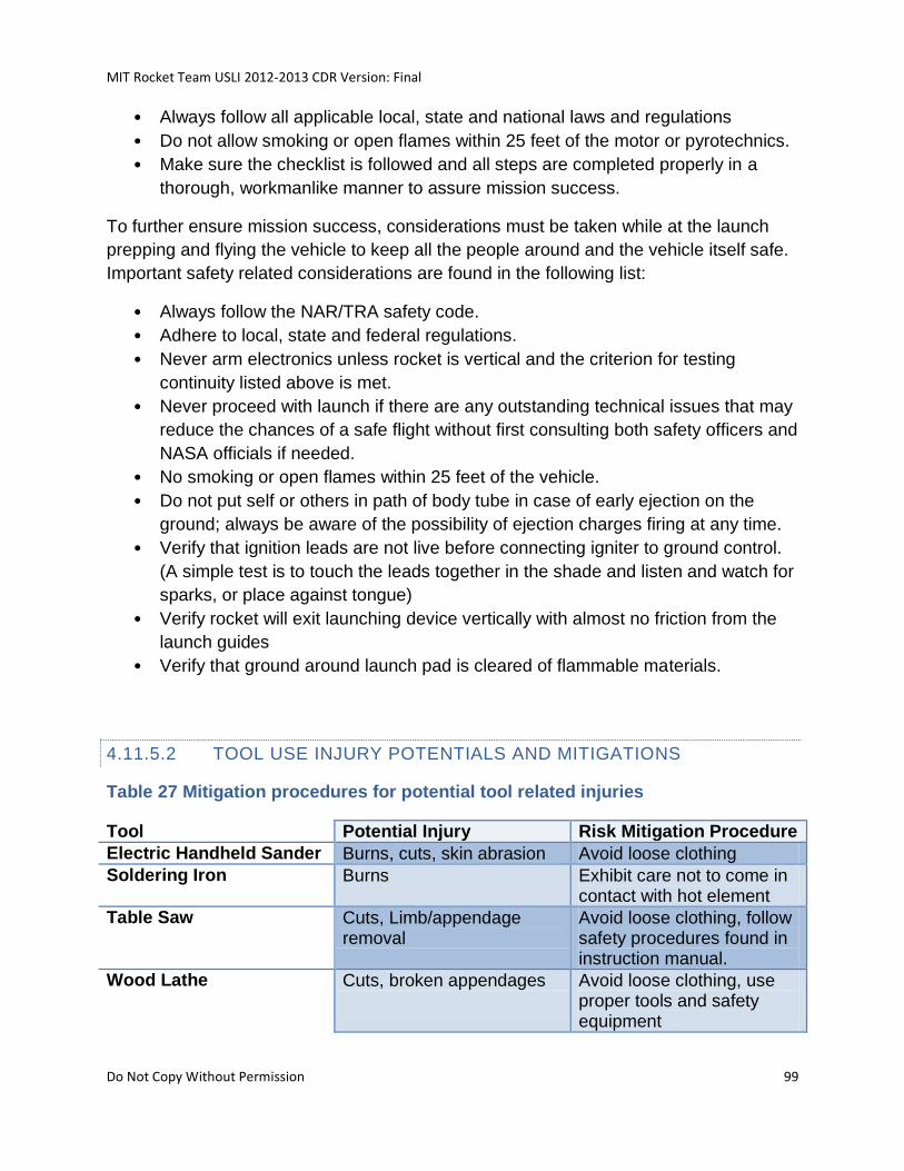
MIT Rocket Team USLI 2012-2013 CDR Version: Final
Do Not Copy Without Permission 99
• Always follow all applicable local, state and national laws and regulations
• Do not allow smoking or open flames within 25 feet of the motor or pyrotechnics.
• Make sure the checklist is followed and all steps are completed properly in a
thorough, workmanlike manner to assure mission success.
To further ensure mission success, considerations must be taken while at the launch
prepping and flying the vehicle to keep all the people around and the vehicle itself safe.
Important safety related considerations are found in the following list:
• Always follow the NAR/TRA safety code.
• Adhere to local, state and federal regulations.
• Never arm electronics unless rocket is vertical and the criterion for testing
continuity listed above is met.
• Never proceed with launch if there are any outstanding technical issues that may
reduce the chances of a safe flight without first consulting both safety officers and
NASA officials if needed.
• No smoking or open flames within 25 feet of the vehicle.
• Do not put self or others in path of body tube in case of early ejection on the
ground; always be aware of the possibility of ejection charges firing at any time.
• Verify that ignition leads are not live before connecting igniter to ground control.
(A simple test is to touch the leads together in the shade and listen and watch for
sparks, or place against tongue)
• Verify rocket will exit launching device vertically with almost no friction from the
launch guides
• Verify that ground around launch pad is cleared of flammable materials.
4.11.5.2 TOOL USE INJURY POTENTIALS AND MITIGATIONS
Table 27 Mitigation procedures for potential tool related injuries
Tool Potential Injury Risk Mitigation Procedure
Electric Handheld Sander Burns, cuts, skin abrasion Avoid loose clothing
Soldering Iron Burns Exhibit care not to come in contact with hot element
Table Saw Cuts, Limb/appendage removal
Avoid loose clothing, follow safety procedures found in instruction manual.
Wood Lathe Cuts, broken appendages Avoid loose clothing, use proper tools and safety equipment
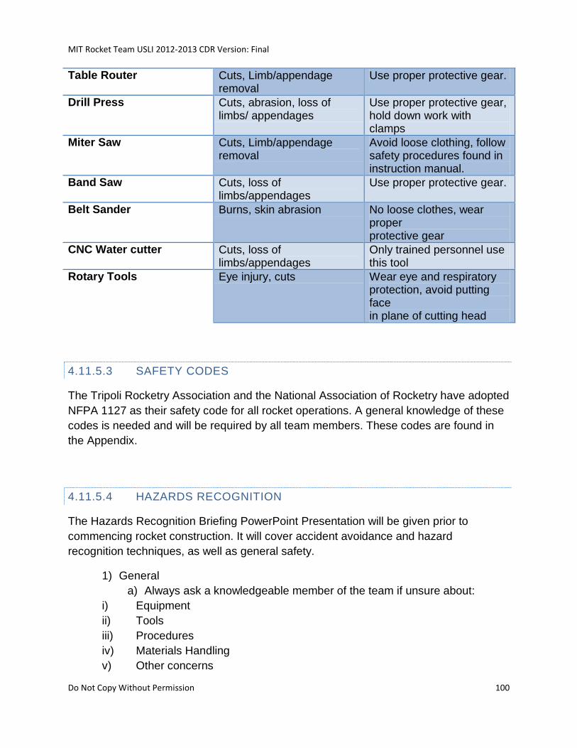
MIT Rocket Team USLI 2012-2013 CDR Version: Final
Do Not Copy Without Permission 100
Table Router Cuts, Limb/appendage removal
Use proper protective gear.
Drill Press Cuts, abrasion, loss of limbs/ appendages
Use proper protective gear, hold down work with clamps
Miter Saw Cuts, Limb/appendage removal
Avoid loose clothing, follow safety procedures found in instruction manual.
Band Saw Cuts, loss of limbs/appendages
Use proper protective gear.
Belt Sander Burns, skin abrasion No loose clothes, wear proper protective gear
CNC Water cutter Cuts, loss of limbs/appendages
Only trained personnel use this tool
Rotary Tools Eye injury, cuts Wear eye and respiratory protection, avoid putting face in plane of cutting head
4.11.5.3 SAFETY CODES
The Tripoli Rocketry Association and the National Association of Rocketry have adopted
NFPA 1127 as their safety code for all rocket operations. A general knowledge of these
codes is needed and will be required by all team members. These codes are found in
the Appendix.
4.11.5.4 HAZARDS RECOGNITION
The Hazards Recognition Briefing PowerPoint Presentation will be given prior to
commencing rocket construction. It will cover accident avoidance and hazard
recognition techniques, as well as general safety.
1) General
a) Always ask a knowledgeable member of the team if unsure about:
i) Equipment
ii) Tools
iii) Procedures
iv) Materials Handling
v) Other concerns
MIT Rocket Team USLI 2012-2013 CDR Version: Final
Do Not Copy Without Permission 101
b) Be cognizant of your own actions and those of others
i) Point out risks and mitigate them
ii) Review procedures and relevant MSDS before commencing potentially hazardous
actions
c) Safety Equipment
i) Only close-toed shoes may be worn in lab
ii) Always wear goggles where applicable
iii) Always use breathing equipment, i.e. face masks, respirators, etc, where
applicable
iv) Always wear gloves where applicable, e.g. when handling epoxy and other
chemicals
2) Chemicals
a) The following are risks of chemical handling:
i) Irritation of skin, eyes, and respiratory system from contact and/or
inhalation of hazardous fumes.
ii) Secondary exposure from chemical spills
iii) Destruction of lab space
b) Ways to mitigate these risks:
i) Whenever using chemicals, refer to MSDS sheets for proper handling
ii) Always wear appropriate safety gear
iii) Keep work stations clean
iv) Keep ventilation pathways clear
v) Always wear appropriate clothing
3) Equipment and Tools
a) The following are risks of equipment and tool handling:
i) Cuts
ii) Burning
iii) General injury
b) Ways to mitigate these risks:
i) Always wear appropriate clothing, e.g. closed-toed shoes.
ii) Always wear appropriate safety equipment
iii) Always ask if unsure
iv) Err on the side of caution
4) Composites Safety
a) Carbon fiber, fiberglass, epoxy, and other composite materials require
special care when handling.
b) The following are risks composites handling:
i) Respiratory irritation
ii) Skin irritation
iii) Eye irritation
MIT Rocket Team USLI 2012-2013 CDR Version: Final
Do Not Copy Without Permission 102
iv) Splinters
v) Secondary exposure
c) Ways to mitigate these risks:
i) Always wear face masks/respirators when sanding, cutting, grinding, etc.,
layups.
ii) Always wear gloves when handling pre-cured composites
iii) Always wear puncture-resistant gloves when handling potentially sharp
composites
iv) A dust-room has been constructed, as per MIT EHS guidelines,
specifically for the handling of composite materials.
d) No team member will handle carbon fiber until properly trained
4.11.6 ENVIRONMENTAL CONCERNS
• All waste materials will be disposed of using proper trash receptacles
• Biodegradable and flame resistant recovery wadding will be used
• Solid rocket motor manufacturers’ instructions will be followed when disposing of
• any rocket motor parts
• Consideration of environmental ramifications will be made regarding applicable
• activities
• Proper blast shields on the launch pad will be used to prevent direct infringement
• of rocket motor exhaust on the ground
• Waste receptacles (trash bags) will be available for use around the prep area to
• encourage proper disposal of waste from rocket prep activities
• The following list of materials have been identified as potentially hazardous:
1. Aeropoxy 2032 Epoxy Resin
2. Aeropoxy 3660 Hardener
3. Ammonium Perchlorate Composite Propellant
4. Black Powder
See Appendix 7 for complete MSDS specifications on these materials.
5 PAYLOAD CRITERIA
The main payload of the rocket will be a quadrotor. The quadrotor will be equipped with
GPS navigation and radio telecommand devices, an IMU, pressure sensors, an onboard
computer, CMOS cameras, IR emitters/detectors, and an autonomous flight stabilizer.
In addition to these components, the craft will also serve as the housing for the SMD
MIT Rocket Team USLI 2012-2013 CDR Version: Final
Do Not Copy Without Permission 103
and high altitude weather payloads (described in the next section). Together these
systems will allow the quadrotor to communicate science data and the relative location
of the ground station to the descending rocket via an optical communication link. A radio
transceiver allows the nose cone under the drogue chute to communicate relevant
science and state information with the ground station. In addition, commercial-off-the-
shelf science payloads (an altimeter and an accelerometer) will be flown on the rocket.
Figure 32 The Current Design of Quadrotor and Science Sensor Suite
Configuration
5.1 SELECTION, DESIGN, AND VERIFICATION OF PAYLOAD
EXPERIMENT
5.1.1 MISSION MOTIVATION
Quadrotors are a common tool used for reconnaissance gathering, object tracking, and
recognition. Their ability to hover at a specified altitude as well as their ability to perform
aerial maneuvers that fixed-winged UAVs cannot makes them a perfect platform for this
science mission. However, as with most small UAVs, the quadrotor requires a long lead
time before the craft can reach high altitudes. Thus, the team aims to reduce this lead
time by building and testing a rotorcraft that can be deployed from high-powered
rockets.
In addition, to provide real-time measurements and control, the quadrotor must
establish a secure and reliable communications channel with the ground user. For this
purpose, optical transmissions and communications have been employed with success
in other applications. However, thus far a robust and cost effective high bandwidth
optical transmission and control method between mobile targets for civilians does not
MIT Rocket Team USLI 2012-2013 CDR Version: Final
Do Not Copy Without Permission 104
yet exist. The team aims to improve on current methods and develop an optical
transmission and control method that can successfully transmit real-time data and
commands to a quadrotor deployed from a rocket.
To provide a comprehensive test of the quadrotor systems, the quadrotor will be
equipped to validate high altitude lightning models through direct measurement. Many
mathematical models used to determine the weather at high altitudes, specifically in
regards to lightning and electrostatic fields, remain untested or unconfirmed due to the
lack of proper in situ measurements, and correlation between changes in the
surrounding environment and visual confirmation of sprite phenomenon. To remedy this,
ultra/very low frequency waves (ULF/VLF), electric field, and magnetic field
measurements have to be taken simultaneously with measurements of lightning
detection and visual data that provide sprite/lightning visual confirmation.
In summary the team aims to:
Decrease deployment time for quadrotor high altitude missions
Improve information acquisition, processing, and transmission on and between
mobile targets in an dynamic environment
Validate high altitude lightning models via direct measurements
5.1.2 MISSION STATEMENT
The MIT Rocket Team aims to develop an inexpensive, customizable, and reusable
rocket system in order to rapidly deploy a quadrotor. The goals of the quadrotor design
are to reduce quadrotor ascent time and to test new methods of communication
between mobile targets. Using the quadrotor as a mobile platform, the team also
intends to develop a payload to study the cause of high altitude lightning discharges and
their effect on the surrounding environment, with the goal of validating existing
mathematical models that lack in situ data.
5.1.3 CONSTRAINTS
Follow all rules of NASA USLI 2012-2013, including but not limited to:
Rocket apogee shall be closest to but not exceeding 5280ft.
At no time may a vehicle exceed 5600ft.
Must carry one NASA designated altimeter for official altitude record
Dual deployment recovery must be used
Dual altimeters must be used for all electronic flight systems.
Each altimeter must have its own battery and externally located arming switch.
MIT Rocket Team USLI 2012-2013 CDR Version: Final
Do Not Copy Without Permission 105
Recovery and payload electronics must be independent from each other.
At all times the system must remain subsonic.
Shear pins must be used in the deployment of both the drogue and main
parachute.
All components of the system must land within 500ft of the launch site in a wind
speed of 15 mi/hr.
Each tethered section, of which there may be no more than 4 of, must land with
kinetic energy of less than 75 ft-lbf
Unmanned aerial vehicle (UAV) payloads of any type shall be tethered to the
vehicle with a remotely controlled release mechanism until the RSO has given
the authority to release the UAV.
Any payload element which is jettisoned during the recovery phase, or after the
launch vehicle lands, shall receive real-time RSO permission prior to initiating the
jettison event.
Scientific method must be used in the collection, analysis and reporting of all
data.
Electronic tracking devices must be used to transmit the location of all
components after landing.
Only commercially available, NAR/TRA certified motors may be used.
Full-scale flight model must be flown prior to FRR.
Students must do 100% of all work for USLI competition related projects
$5000 maximum value of rocket and science payload as it sits on the launch pad.
5.1.4 MISSION REQUIRMENTS
The mission requirements are as follows:
The SPRITE Payload will meet the following objectives:
o Deployable from a rocket
o Safely house all hardware and electronics during all phases of the
mission: launch, normal operations, and recovery
o Relay telemetry and video to the ground station
o Relay telemetry to the nose cone via optical communication
o Track the nose cone and ground station
The HALO Payload will meet the following objectives in addition to the NASA
Science Mission Directorate requirements:
o Ability to detect high altitude “lightning” events
o Gather atmospheric measurements of: the magnetic field, EMF radiation,
ULF/VLF waves, and the local electric field.
MIT Rocket Team USLI 2012-2013 CDR Version: Final
Do Not Copy Without Permission 106
o Gather atmospheric measurements of: pressure, temperature, relative
humidity, solar irradiance, and ultraviolet radiation at a frequency no less
than once every 5 seconds upon decent, and no less than once every
minute after landing.
o Take at least two still photographs during decent, and at least 3 after
landing.
o All pictures must be in an orientation such that the sky is at the top of the
frame.
o All data must be transmitted to ground station after completion of surface
operations.
5.1.5 SYSTEM REQUIREMENTS
The system requirements are as follows:
System must be less than $5000 fair market value at time of flight
Rocket must reliably and accurately achieve apogee of 5280ft
Reliably deploy quadrotor at safe working altitude of 500ft
Stream telemetry, and video to ground station
Employ video and beacon tracking systems.
Quadrotor must have attitude control within 5 degrees of accuracy during normal
operations
Quadrotor must have basic altitude control with 2 meters of accuracy during
normal operations
Quadrotor must be able to hover for a minimum of five minutes and operate for
30 minutes in a low power state (no power supplied to the propulsion system).
5.1.6 REQUIREMENT VERIFICATION BY DESIGN
5.1.7 PAYLOAD HYPOTHESIS
1. A composite based quadrotor with a maximum weight of 10lbs and a maximum
cost of $2000 dollars can track an object up to 300 feet away, recognized objects
on the ground while at a minimum distance of 1000 feet in the air, and can collect
and transmit data to the ground.
2. The HALO suite of sensors can reliably and robustly collect, store, and transmit
data.
5.1.8 SUCCESS CRITERIA
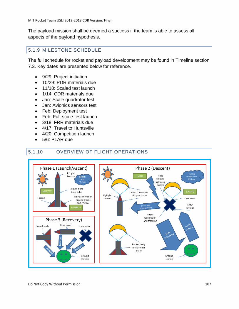
MIT Rocket Team USLI 2012-2013 CDR Version: Final
Do Not Copy Without Permission 107
The payload mission shall be deemed a success if the team is able to assess all
aspects of the payload hypothesis.
5.1.9 MILESTONE SCHEDULE
The full schedule for rocket and payload development may be found in Timeline section
7.3. Key dates are presented below for reference.
9/29: Project initiation
10/29: PDR materials due
11/18: Scaled test launch
1/14: CDR materials due
Jan: Scale quadrotor test
Jan: Avionics sensors test
Feb: Deployment test
Feb: Full-scale test launch
3/18: FRR materials due
4/17: Travel to Huntsville
4/20: Competition launch
5/6: PLAR due
5.1.10 OVERVIEW OF FLIGHT OPERATIONS
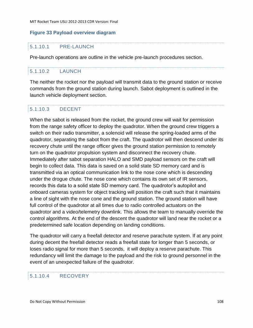
MIT Rocket Team USLI 2012-2013 CDR Version: Final
Do Not Copy Without Permission 108
Figure 33 Payload overview diagram
5.1.10.1 PRE-LAUNCH
Pre-launch operations are outline in the vehicle pre-launch procedures section.
5.1.10.2 LAUNCH
The neither the rocket nor the payload will transmit data to the ground station or receive
commands from the ground station during launch. Sabot deployment is outlined in the
launch vehicle deployment section.
5.1.10.3 DECENT
When the sabot is released from the rocket, the ground crew will wait for permission
from the range safety officer to deploy the quadrotor. When the ground crew triggers a
switch on their radio transmitter, a solenoid will release the spring-loaded arms of the
quadrotor, separating the sabot from the craft. The quadrotor will then descend under its
recovery chute until the range officer gives the ground station permission to remotely
turn on the quadrotor propulsion system and disconnect the recovery chute.
Immediately after sabot separation HALO and SMD payload sensors on the craft will
begin to collect data. This data is saved on a solid state SD memory card and is
transmitted via an optical communication link to the nose cone which is descending
under the drogue chute. The nose cone which contains its own set of IR sensors,
records this data to a solid state SD memory card. The quadrotor’s autopilot and
onboard cameras system for object tracking will position the craft such that it maintains
a line of sight with the nose cone and the ground station. The ground station will have
full control of the quadrotor at all times due to radio controlled actuators on the
quadrotor and a video/telemetry downlink. This allows the team to manually override the
control algorithms. At the end of the descent the quadrotor will land near the rocket or a
predetermined safe location depending on landing conditions.
The quadrotor will carry a freefall detector and reserve parachute system. If at any point
during decent the freefall detector reads a freefall state for longer than 5 seconds, or
loses radio signal for more than 5 seconds, it will deploy a reserve parachute. This
redundancy will limit the damage to the payload and the risk to ground personnel in the
event of an unexpected failure of the quadrotor.
5.1.10.4 RECOVERY
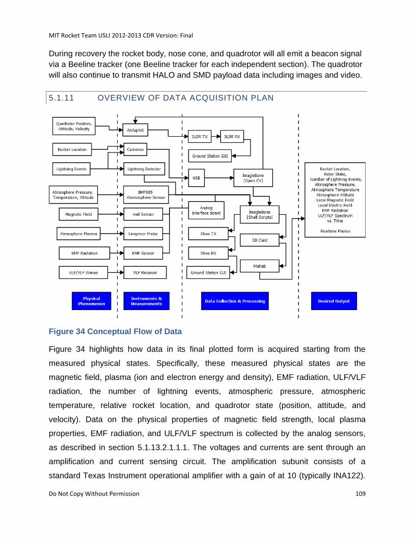
MIT Rocket Team USLI 2012-2013 CDR Version: Final
Do Not Copy Without Permission 109
During recovery the rocket body, nose cone, and quadrotor will all emit a beacon signal
via a Beeline tracker (one Beeline tracker for each independent section). The quadrotor
will also continue to transmit HALO and SMD payload data including images and video.
5.1.11 OVERVIEW OF DATA ACQUISITION PLAN
Figure 34 Conceptual Flow of Data
Figure 34 highlights how data in its final plotted form is acquired starting from the
measured physical states. Specifically, these measured physical states are the
magnetic field, plasma (ion and electron energy and density), EMF radiation, ULF/VLF
radiation, the number of lightning events, atmospheric pressure, atmospheric
temperature, relative rocket location, and quadrotor state (position, attitude, and
velocity). Data on the physical properties of magnetic field strength, local plasma
properties, EMF radiation, and ULF/VLF spectrum is collected by the analog sensors,
as described in section 5.1.13.2.1.1.1. The voltages and currents are sent through an
amplification and current sensing circuit. The amplification subunit consists of a
standard Texas Instrument operational amplifier with a gain of at 10 (typically INA122).
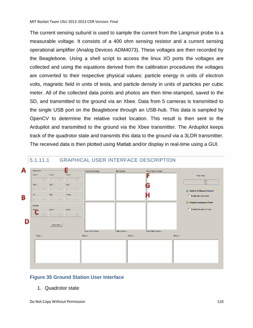
MIT Rocket Team USLI 2012-2013 CDR Version: Final
Do Not Copy Without Permission 110
The current sensing subunit is used to sample the current from the Langmuir probe to a
measurable voltage. It consists of a 400 ohm sensing resistor and a current sensing
operational amplifier (Analog Devices ADM4073). These voltages are then recorded by
the Beaglebone. Using a shell script to access the linux I/O ports the voltages are
collected and using the equations derived from the calibration procedures the voltages
are converted to their respective physical values: particle energy in units of electron
volts, magnetic field in units of tesla, and particle density in units of particles per cubic
meter. All of the collected data points and photos are then time-stamped, saved to the
SD, and transmitted to the ground via an Xbee. Data from 5 cameras is transmitted to
the single USB port on the Beaglebone through an USB-hub. This data is sampled by
OpenCV to determine the relative rocket location. This result is then sent to the
Ardupilot and transmitted to the ground via the Xbee transmitter. The Ardupilot keeps
track of the quadrotor state and transmits this data to the ground via a 3LDR transmitter.
The received data is then plotted using Matlab and/or display in real-time using a GUI.
5.1.11.1 GRAPHICAL USER INTERFACE DESCRIPTION
Figure 35 Ground Station User Interface
1. Quadrotor state
MIT Rocket Team USLI 2012-2013 CDR Version: Final
Do Not Copy Without Permission 111
2. Rocket state
3. Save data function
4. Real-time science data plots
5. Real-time images from cameras mounted on rotorcraft
6. Time since quadrotor deployment
7. Manuel control switch
8. Emergency parachute deploy switch
5.1.12 OVERVIEW: SPRITE
Specialized Rotorcraft for IR Communications, Object Tracking and On-board
Experiments
5.1.12.1 MOTIVATION
Please see section 5.1.1.
5.1.12.2 CONCEPT OF OPERATIONS
The Quadrotor will be packaged within a sabot inside the rocket. About 20 minutes
before launch, the quadrotor avionics will be powered on, and will remain in a low-power
dormant state. During decent, the sabot containing the quadrotor will be deployed from
the rocket at an altitude of 2000ft.
The quadrotor will then wait for a signal indicating permission form the range officer to
open the sabot. When the signal is received, springs within the quadrotor will push the
sabot apart, and the quadrotor main parachute, packed in the sabot with the quadrotor,
will unfold. The quadrotor will then descend suspended from the quadrotor main
parachute. The quadrotor avionics will begin to broadcast telemetry data back to the
ground station, and will continue to do so until turned off. The quadrotor will then
activate its reserve parachute system. From this point on, a five-second fall or five
second radio signal loss will cause the reserve parachutes to be deployed.
Next, the quadrotor will perform a series of checks to ensure that its arms have unfolded
property, and that its motors, power supply, and sensors are in working order. If these
checks fail, the quadrotor will remain on its main parachute for the entire decent. These
checks will take approximately 1 second.
The quadrotor will then wait for a signal indicating that the range officer has given
permission to detach from the quadrotor main parachute. When this signal is received
MIT Rocket Team USLI 2012-2013 CDR Version: Final
Do Not Copy Without Permission 112
the quadrotor will cut away its main parachute, fall for 1 second to move itself away from
the parachute, and will begin to fly under power.
The quadrotor will perform its flight mission, during which it will track and follow the
rocket nosecone. At any time during the flight mission, the ground station crew may
assume remote manual control of the quadrotor’s flight, or may remotely deploy the
reserve parachute. During the flight mission, the science payload will perform data
collection and transmit data back to the ground station. The flight mission will last
approximately 10 minutes.
After the flight mission is concluded, the quadrotor will enter a landing sequence. The
quadrotor’s autopilot will use GPS and barometer altitude data for the initial landing
approach, and will use more accurate sonar data for the final approach once within 10
meters of the ground. Landing will be confirmed by contact sensors in the landing gear.
After landing, the recovery team will use GPS data transmitted by the quadrotor to
locate and recover it. The team plans to recover the quadrotor within 20 minutes of
landing.
MIT Rocket Team USLI 2012-2013 CDR Version: Final
Do Not Copy Without Permission 113
Figure 36 Concept of Operations Diagram - Time is shown on the downwards
axis. Diamonds represent decisions, rectangles represent processes, rounded
rectangles represent looping or continuous processes, and slanted
parallelograms represent inputs. The black path indicates the intended operation;
the dashed red paths indicate controlled failure modes.
MIT Rocket Team USLI 2012-2013 CDR Version: Final
Do Not Copy Without Permission 114
5.1.12.3 STRUCTURES
The quadrotor will be housed inside a sabot in the body tube of the rocket. In order to fit
within the confined space of the body tube, the vehicle will be designed with foldable
arms which allow it to be compacted prior to flight. When the craft leaves the sabot,
internal springs will open and lock into place the each of the four arms to prepare the
vehicle for flight. The sabot will be made from a phenolic tube and filled with foam. Not
only is this easy to assemble, it also gives the quadrotor shock protection and allows the
craft to use the force of its extending arms to push apart the sabot. To ensure that all
parts are recovered, the sabot sections will remain tethered to the rocket nose cone
after quadrotor deployment.
The physical and mechanical properties for the quadrotor are defined based on rocket
body size and mass constraints. The baseline design of the vehicle contains 4 motors,
ESCs, arms, and non-folding propellers. As the quadrotor must fit within a 6 inch
diameter, 3.5 foot long tube, the maximum arm length is 1.5 feet with a 6 inch buffer on
each end. The arms and SPRITE components and science payloads are attached to the
thick 5 inch diagonal square quadrotor base. This results in a maximum propeller
diameter of about 1.5 foot which meets our design requirements. In terms of space, the
limiting factor is the 6 inch tube diameter. After considering baffle, padding, and the tube
case, the usable diameter reduces to 5.75 inches or a 2.875 inch radius. Assuming the
propeller, motor shaft, and arm take up an inch of radius, then that leaves 1.875 inch
(the reduces to 1 inch after wires are considered) when the arms are folded down. A
direct drive brushless 830W Turnigy SK3 Motor with a 42 millimeter diameter was
chosen as it provides suitable thrust for its size. The motor will be positioned below the
propeller. The static thrust for the motor was calculated using www.ecalc.ch (good for
static thrust with an accuracy of about +/-10%); this resulted in a thrust of 6.5 lbs per
motor with a 7 minute flight time (with 4S, 6Ah LiPo per motor). This leads to a
conservative weight of 24 lbs; with 50% margin this gives a maximum quadrotor weight,
including payloads, of approximately 12 lbs.
The quadrotor will be built around an arm mounting block. The arm mounting block will
confine the arms so that they rotate about a pivot in the horizontal plane of the
quadrotor, and will contain a locking mechanism which will hold the arms in place once
opened. The locking mechanism will consist of a button spring on each arm which will
pop up into a hole in the arm mounting block when the arm is fully unfolded. Springs in
the arm mounting block will push the arms into the unfolded and locked position when
the arms are released from the folded configuration.
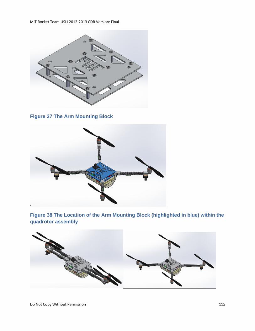
MIT Rocket Team USLI 2012-2013 CDR Version: Final
Do Not Copy Without Permission 115
Figure 37 The Arm Mounting Block
Figure 38 The Location of the Arm Mounting Block (highlighted in blue) within the
quadrotor assembly
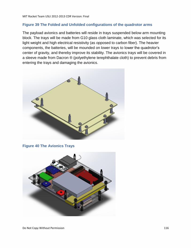
MIT Rocket Team USLI 2012-2013 CDR Version: Final
Do Not Copy Without Permission 116
Figure 39 The Folded and Unfolded configurations of the quadrotor arms
The payload avionics and batteries will reside in trays suspended below arm mounting
block. The trays will be made from G10 glass cloth laminate, which was selected for its
light weight and high electrical resistivity (as opposed to carbon fiber). The heavier
components, the batteries, will be mounded on lower trays to lower the quadrotor’s
center of gravity, and thereby improve its stability. The avionics trays will be covered in
a sleeve made from Dacron ® (polyethylene terephthalate cloth) to prevent debris from
entering the trays and damaging the avionics.
Figure 40 The Avionics Trays
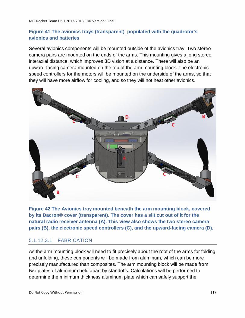
MIT Rocket Team USLI 2012-2013 CDR Version: Final
Do Not Copy Without Permission 117
Figure 41 The avionics trays (transparent) populated with the quadrotor's
avionics and batteries
Several avionics components will be mounted outside of the avionics tray. Two stereo
camera pairs are mounted on the ends of the arms. This mounting gives a long stereo
interaxial distance, which improves 3D vision at a distance. There will also be an
upward-facing camera mounted on the top of the arm mounting block. The electronic
speed controllers for the motors will be mounted on the underside of the arms, so that
they will have more airflow for cooling, and so they will not heat other avionics.
Figure 42 The Avionics tray mounted beneath the arm mounting block, covered
by its Dacron® cover (transparent). The cover has a slit cut out of it for the
natural radio receiver antenna (A). This view also shows the two stereo camera
pairs (B), the electronic speed controllers (C), and the upward-facing camera (D).
5.1.12.3.1 FABRICATION
As the arm mounting block will need to fit precisely about the root of the arms for folding
and unfolding, these components will be made from aluminum, which can be more
precisely manufactured than composites. The arm mounting block will be made from
two plates of aluminum held apart by standoffs. Calculations will be performed to
determine the minimum thickness aluminum plate which can safely support the
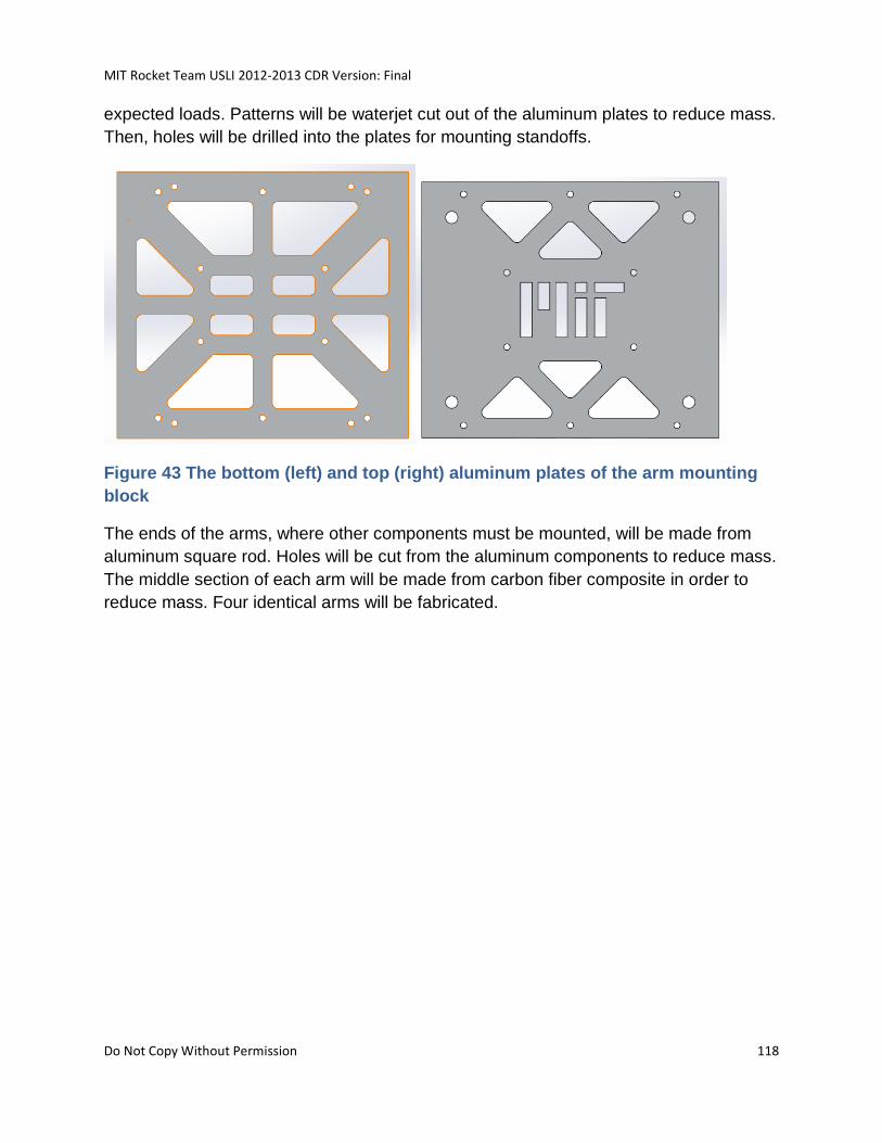
MIT Rocket Team USLI 2012-2013 CDR Version: Final
Do Not Copy Without Permission 118
expected loads. Patterns will be waterjet cut out of the aluminum plates to reduce mass.
Then, holes will be drilled into the plates for mounting standoffs.
Figure 43 The bottom (left) and top (right) aluminum plates of the arm mounting
block
The ends of the arms, where other components must be mounted, will be made from
aluminum square rod. Holes will be cut from the aluminum components to reduce mass.
The middle section of each arm will be made from carbon fiber composite in order to
reduce mass. Four identical arms will be fabricated.
MIT Rocket Team USLI 2012-2013 CDR Version: Final
Do Not Copy Without Permission 119
Figure 44 One of four arms, made from aluminum and carbon fiber.
Then the arms will be assembled into the arm mounting block. First, the bottom plate of
the arm mounting block will be populated with standoffs (Assembly Step 1). The four
rounded standoffs in the middle of the plate will be pivots for the arms. Second, the
arms will be slipped onto their pivots (Assembly Step 2). Third, the top plate of the arm
mounting block will be screwed to the standoffs, sandwiching the arms in place
(Assembly Step 3).
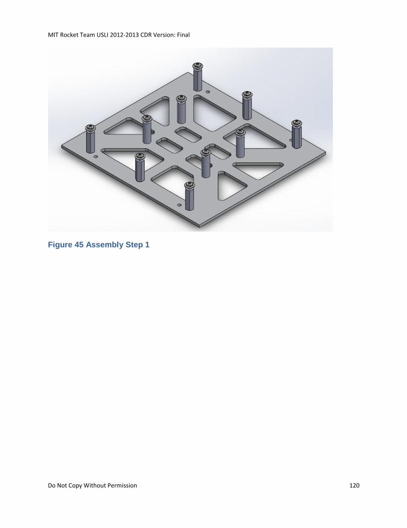
MIT Rocket Team USLI 2012-2013 CDR Version: Final
Do Not Copy Without Permission 120
Figure 45 Assembly Step 1
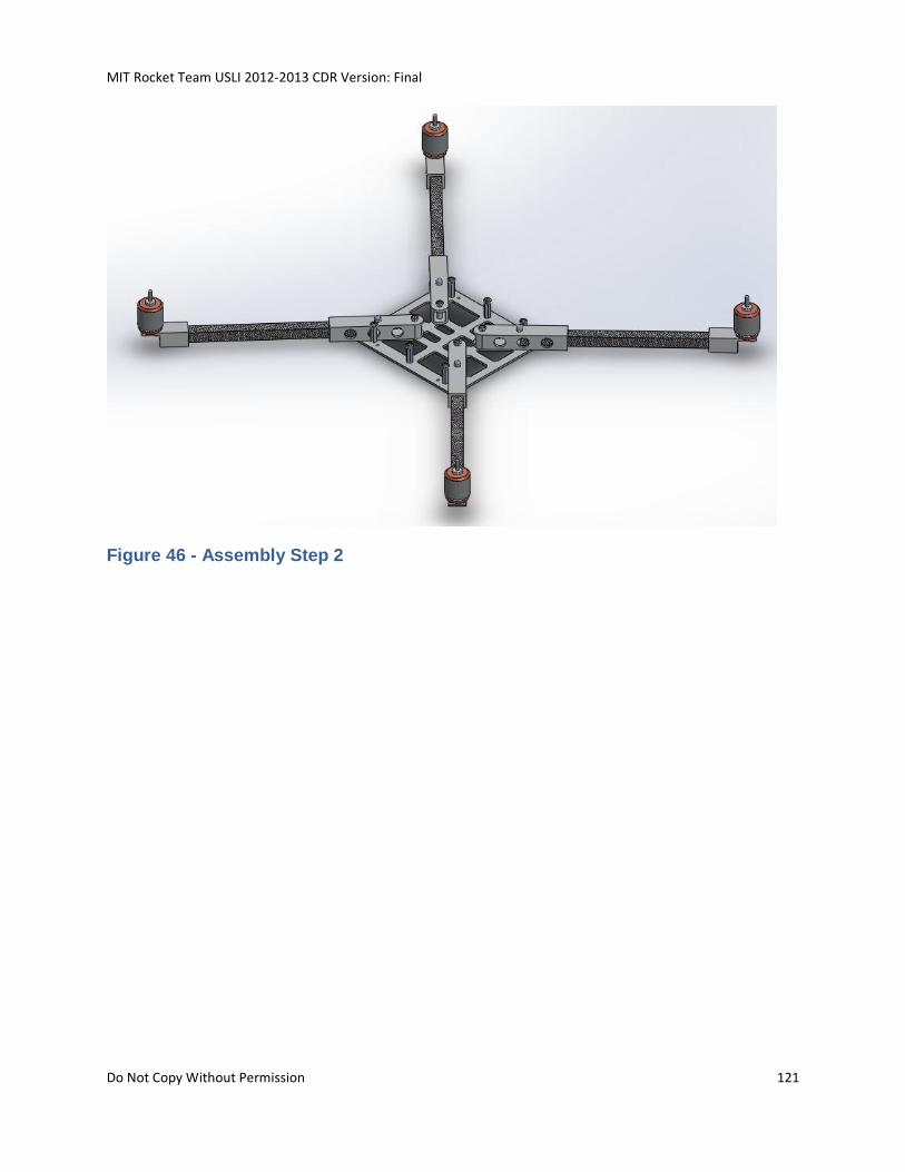
MIT Rocket Team USLI 2012-2013 CDR Version: Final
Do Not Copy Without Permission 121
Figure 46 - Assembly Step 2
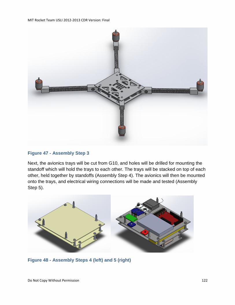
MIT Rocket Team USLI 2012-2013 CDR Version: Final
Do Not Copy Without Permission 122
Figure 47 - Assembly Step 3
Next, the avionics trays will be cut from G10, and holes will be drilled for mounting the
standoff which will hold the trays to each other. The trays will be stacked on top of each
other, held together by standoffs (Assembly Step 4). The avionics will then be mounted
onto the trays, and electrical wiring connections will be made and tested (Assembly
Step 5).
Figure 48 - Assembly Steps 4 (left) and 5 (right)
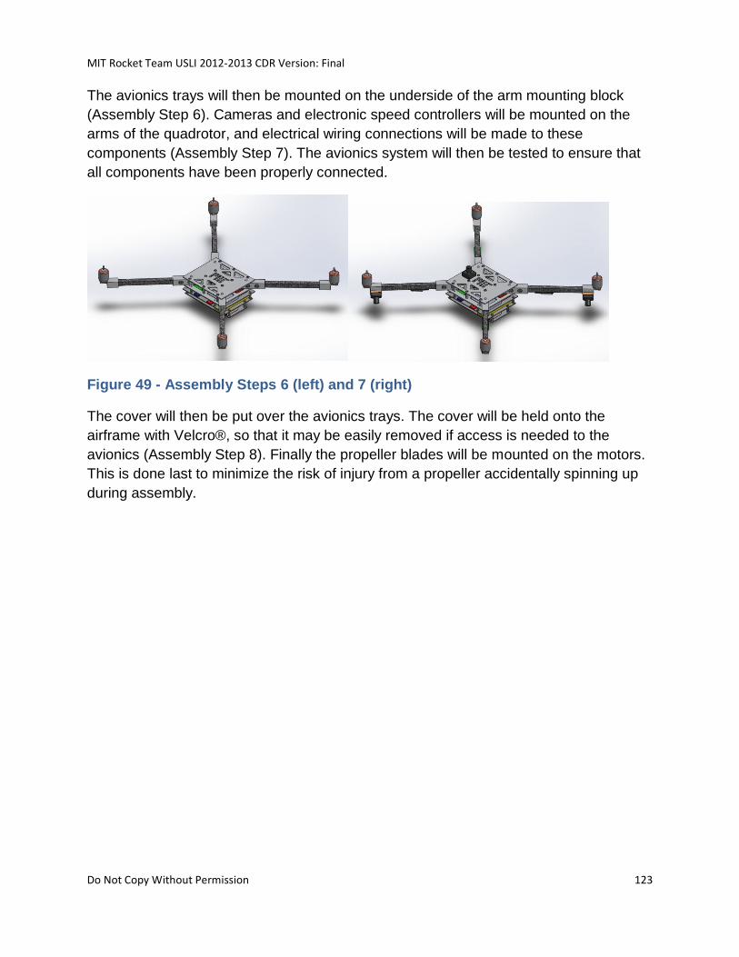
MIT Rocket Team USLI 2012-2013 CDR Version: Final
Do Not Copy Without Permission 123
The avionics trays will then be mounted on the underside of the arm mounting block
(Assembly Step 6). Cameras and electronic speed controllers will be mounted on the
arms of the quadrotor, and electrical wiring connections will be made to these
components (Assembly Step 7). The avionics system will then be tested to ensure that
all components have been properly connected.
Figure 49 - Assembly Steps 6 (left) and 7 (right)
The cover will then be put over the avionics trays. The cover will be held onto the
airframe with Velcro®, so that it may be easily removed if access is needed to the
avionics (Assembly Step 8). Finally the propeller blades will be mounted on the motors.
This is done last to minimize the risk of injury from a propeller accidentally spinning up
during assembly.
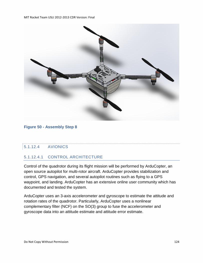
MIT Rocket Team USLI 2012-2013 CDR Version: Final
Do Not Copy Without Permission 124
Figure 50 - Assembly Step 8
5.1.12.4 AVIONICS
5.1.12.4.1 CONTROL ARCHITECTURE
Control of the quadrotor during its flight mission will be performed by ArduCopter, an
open source autopilot for multi-rotor aircraft. ArduCopter provides stabilization and
control, GPS navigation, and several autopilot routines such as flying to a GPS
waypoint, and landing. ArduCopter has an extensive online user community which has
documented and tested the system.
ArduCopter uses an 3-axis accelerometer and gyroscope to estimate the attitude and
rotation rates of the quadrotor. Particularly, ArduCopter uses a nonlinear
complementary filter (NCF) on the SO(3) group to fuse the accelerometer and
gyroscope data into an attitude estimate and attitude error estimate.
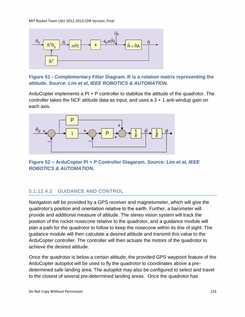
MIT Rocket Team USLI 2012-2013 CDR Version: Final
Do Not Copy Without Permission 125
Figure 51 - Complementary Filter Diagram. R is a rotation matrix representing the
attitude. Source: Lim et al, IEEE ROBOTICS & AUTOMATION.
ArduCopter implements a PI + P controller to stabilize the attitude of the quadrotor. The
controller takes the NCF attitude data as input, and uses a 3 + 1 anti-windup gain on
each axis.
Figure 52 – ArduCopter PI + P Controller Diagaram. Source: Lim et al, IEEE
ROBOTICS & AUTOMATION.
5.1.12.4.2 GUIDANCE AND CONTROL
Navigation will be provided by a GPS receiver and magnetometer, which will give the
quadrotor’s position and orientation relative to the earth. Further, a barometer will
provide and additional measure of altitude. The stereo vision system will track the
position of the rocket nosecone relative to the quadrotor, and a guidance module will
plan a path for the quadrotor to follow to keep the nosecone within its line of sight. The
guidance module will then calculate a desired attitude and transmit this value to the
ArduCopter controller. The controller will then actuate the motors of the quadrotor to
achieve the desired attitude.
Once the quadrotor is below a certain altitude, the provided GPS waypoint feature of the
ArduCopter autopilot will be used to fly the quadrotor to coordinates above a pre-
determined safe landing area. The autopilot may also be configured to select and travel
to the closest of several pre-determined landing areas. Once the quadrotor has
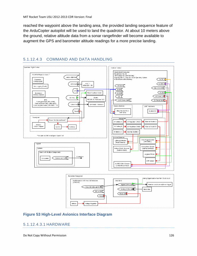
MIT Rocket Team USLI 2012-2013 CDR Version: Final
Do Not Copy Without Permission 126
reached the waypoint above the landing area, the provided landing sequence feature of
the ArduCopter autopilot will be used to land the quadrotor. At about 10 meters above
the ground, relative altitude data from a sonar rangefinder will become available to
augment the GPS and barometer altitude readings for a more precise landing.
5.1.12.4.3 COMMAND AND DATA HANDLING
Figure 53 High-Level Avionics Interface Diagram
5.1.12.4.3.1 HARDWARE
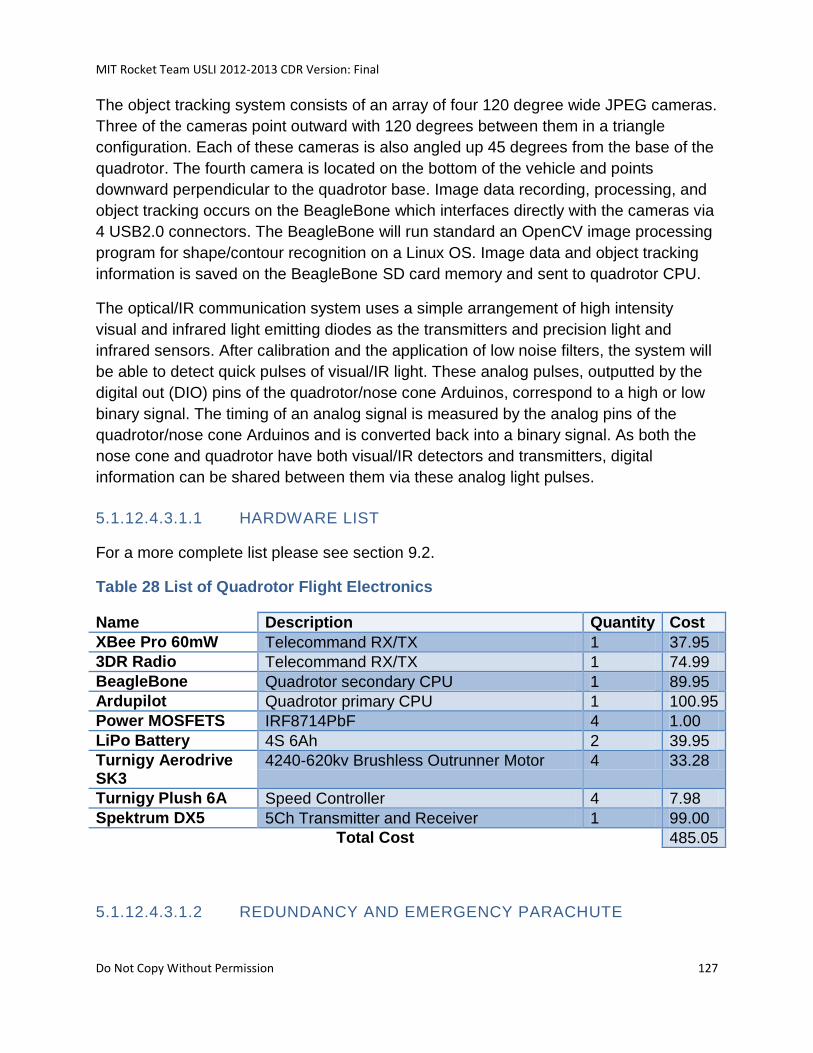
MIT Rocket Team USLI 2012-2013 CDR Version: Final
Do Not Copy Without Permission 127
The object tracking system consists of an array of four 120 degree wide JPEG cameras.
Three of the cameras point outward with 120 degrees between them in a triangle
configuration. Each of these cameras is also angled up 45 degrees from the base of the
quadrotor. The fourth camera is located on the bottom of the vehicle and points
downward perpendicular to the quadrotor base. Image data recording, processing, and
object tracking occurs on the BeagleBone which interfaces directly with the cameras via
4 USB2.0 connectors. The BeagleBone will run standard an OpenCV image processing
program for shape/contour recognition on a Linux OS. Image data and object tracking
information is saved on the BeagleBone SD card memory and sent to quadrotor CPU.
The optical/IR communication system uses a simple arrangement of high intensity
visual and infrared light emitting diodes as the transmitters and precision light and
infrared sensors. After calibration and the application of low noise filters, the system will
be able to detect quick pulses of visual/IR light. These analog pulses, outputted by the
digital out (DIO) pins of the quadrotor/nose cone Arduinos, correspond to a high or low
binary signal. The timing of an analog signal is measured by the analog pins of the
quadrotor/nose cone Arduinos and is converted back into a binary signal. As both the
nose cone and quadrotor have both visual/IR detectors and transmitters, digital
information can be shared between them via these analog light pulses.
5.1.12.4.3.1.1 HARDWARE LIST
For a more complete list please see section 9.2.
Table 28 List of Quadrotor Flight Electronics
Name Description Quantity Cost
XBee Pro 60mW Telecommand RX/TX 1 37.95
3DR Radio Telecommand RX/TX 1 74.99
BeagleBone Quadrotor secondary CPU 1 89.95
Ardupilot Quadrotor primary CPU 1 100.95
Power MOSFETS IRF8714PbF 4 1.00
LiPo Battery 4S 6Ah 2 39.95
Turnigy Aerodrive SK3
4240-620kv Brushless Outrunner Motor 4 33.28
Turnigy Plush 6A Speed Controller 4 7.98
Spektrum DX5 5Ch Transmitter and Receiver 1 99.00
Total Cost 485.05
5.1.12.4.3.1.2 REDUNDANCY AND EMERGENCY PARACHUTE
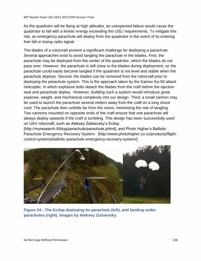
MIT Rocket Team USLI 2012-2013 CDR Version: Final
Do Not Copy Without Permission 128
As the quadrotor will be flying at high altitudes, an unexpected failure would cause the
quadrotor to fall with a kinetic energy exceeding the USLI requirements. To mitigate this
risk, an emergency parachute will deploy from the quadrotor in the event of its entering
free fall or losing radio signal.
The blades of a rotorcraft present a significant challenge for deploying a parachute.
Several approaches exist to avoid tangling the parachute in the blades. First, the
parachute may be deployed from the center of the quadrotor, which the blades do not
pass over. However, the parachute is still close to the blades during deployment, so the
parachute could easily become tangled if the quadrotor is not level and stable when the
parachute deploys. Second, the blades can be removed from the rotorcraft prior to
deploying the parachute system. This is the approach taken by the Kamov Ka-50 attack
helicopter, in which explosive bolts detach the blades from the craft before the ejection
seat and parachute deploy. However, building such a system would introduce great
expense, weight, and mechanical complexity into our design. Third, a small cannon may
be used to launch the parachute several meters away from the craft on a long shock
cord. The parachute then unfolds far from the rotors, minimizing the risk of tangling.
Two cannons mounted on opposite ends of the craft ensure that one parachute will
always deploy upwards if the craft is tumbling. This design has been successfully used
on UAV rotorcraft, such as Aleksey Zaitsevsky’s Ecilop
[http://myresearch.lt/blog/parachute/parachute.phtml], and Photo Higher’s Ballistic
Parachute Emergency Recovery System. [http://www.photohigher.co.nz/products/flight-
control-systems/ballistic-parachute-emergency-recovery-system/].
Figure 54 - The Ecilop deploying its parachute (left), and landing under
parachutes (right). Images by Aleksey Zuitsevsky.
MIT Rocket Team USLI 2012-2013 CDR Version: Final
Do Not Copy Without Permission 129
As the cannon recovery system reduces tangling risk while maintaining mechanical
simplicity, and has been successfully implemented on UAV rotocraft, it will be used as
the design for our system.
Parachute Sizing
To meet USLI’s safety requirements, the quadrotor must fall with less than 75 lbf ft [102
J] of kinetic energy. Assuming a 6.6 lb [3 kg] quadrotor, the reserve parachute system
must slow the terminal velocity to 26 ft/s [8 m/s]. Assuming a parachute with a
coefficient of drag of 0.7, 11 ft2 [1 m2 ] of parachute area is required. Each of the two
parachutes will have this area, so that the quadrotor will still fall with an acceptable
kinetic energy if only one parachute deploys successfully. 48 in diameter parachutes are
the smallest standard size having at least 11 ft2 [1 m2 ]of parachute area.
Manufacturers list 48 in nylon parachutes as having a mass of 0.22 – 0.29 lbs [100 -130
g].
Design
The cannon will be made from a carbon-fiber tube with a circular aluminum plate at one
end. Mounting hardware will attach the aluminum plate to the arm of the quadrotor.
The cannon must be made as light as possible while not failing under the pressure load
from the explosive charge. Thinner walls on the tube and plate will reduce the mass of
the system, but too-thin walls will rupture. To determine the optimal thickness, the load
placed on the cannon by the explosion must be known. A Forward-Euler simulation
was used to model the pressure in the cannon as the projectile moves down the barrel.
The model assumes that the combustion gasses behave as an ideal gas.
Using a 2 in ID, 6 in [15 cm] long carbon fiber tube from DragonPlate, and assuming a
0.22 lb [100 g] parachute, and a 2 g black powder charge, the simulation indicates a
maximum pressure of 1260 psi [8,700,000 Pa]. The simulation predicts that the exit
velocity will be 40 ft/s [12 m/s], which should be sufficient to get the parachute clear of
the rotors. Simulation graphs are shown below for2 g and 4 g black powder charges.
The simulation predicts that a 1 g charge will be insufficient to eject the parachute from
the tube. .
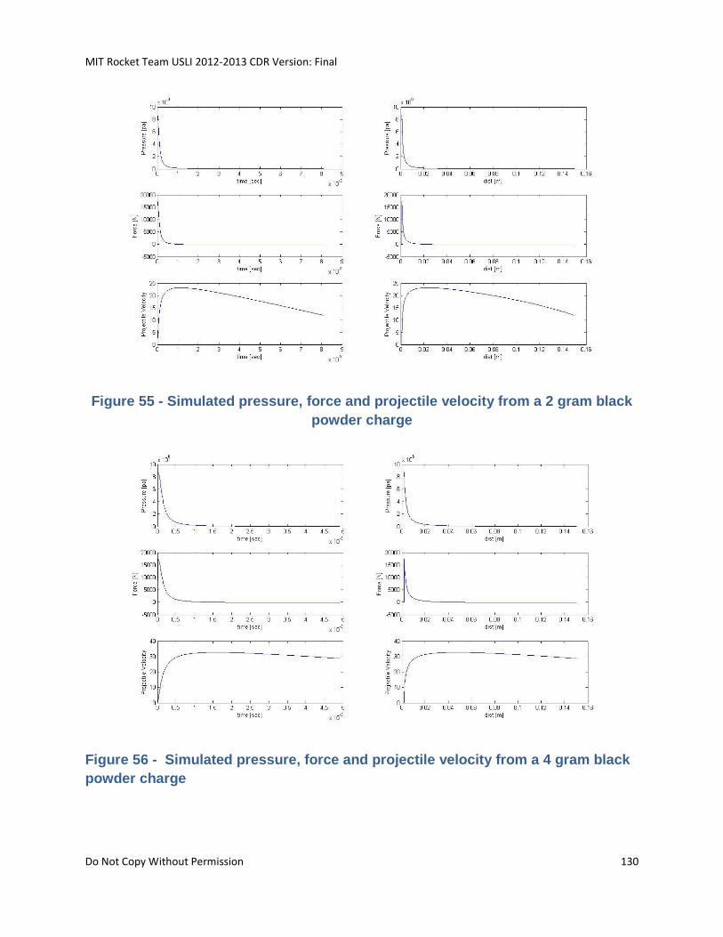
MIT Rocket Team USLI 2012-2013 CDR Version: Final
Do Not Copy Without Permission 130
Figure 55 - Simulated pressure, force and projectile velocity from a 2 gram black
powder charge
Figure 56 - Simulated pressure, force and projectile velocity from a 4 gram black
powder charge
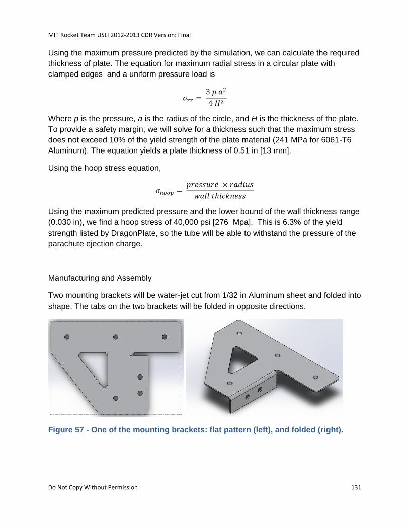
MIT Rocket Team USLI 2012-2013 CDR Version: Final
Do Not Copy Without Permission 131
Using the maximum pressure predicted by the simulation, we can calculate the required
thickness of plate. The equation for maximum radial stress in a circular plate with
clamped edges and a uniform pressure load is
Where p is the pressure, a is the radius of the circle, and H is the thickness of the plate.
To provide a safety margin, we will solve for a thickness such that the maximum stress
does not exceed 10% of the yield strength of the plate material (241 MPa for 6061-T6
Aluminum). The equation yields a plate thickness of 0.51 in [13 mm].
Using the hoop stress equation,
Using the maximum predicted pressure and the lower bound of the wall thickness range
(0.030 in), we find a hoop stress of 40,000 psi [276 Mpa]. This is 6.3% of the yield
strength listed by DragonPlate, so the tube will be able to withstand the pressure of the
parachute ejection charge.
Manufacturing and Assembly
Two mounting brackets will be water-jet cut from 1/32 in Aluminum sheet and folded into
shape. The tabs on the two brackets will be folded in opposite directions.
Figure 57 - One of the mounting brackets: flat pattern (left), and folded (right).
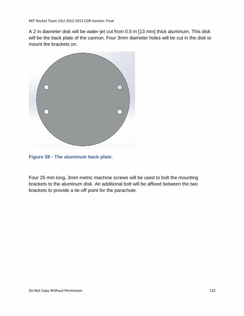
MIT Rocket Team USLI 2012-2013 CDR Version: Final
Do Not Copy Without Permission 132
A 2 in diameter disk will be water-jet cut from 0.5 in [13 mm] thick aluminum. This disk
will be the back plate of the cannon. Four 3mm diameter holes will be cut in the disk to
mount the brackets on.
Figure 58 - The aluminum back plate.
Four 25 mm long, 3mm metric machine screws will be used to bolt the mounting
brackets to the aluminum disk. An additional bolt will be affixed between the two
brackets to provide a tie-off point for the parachute.
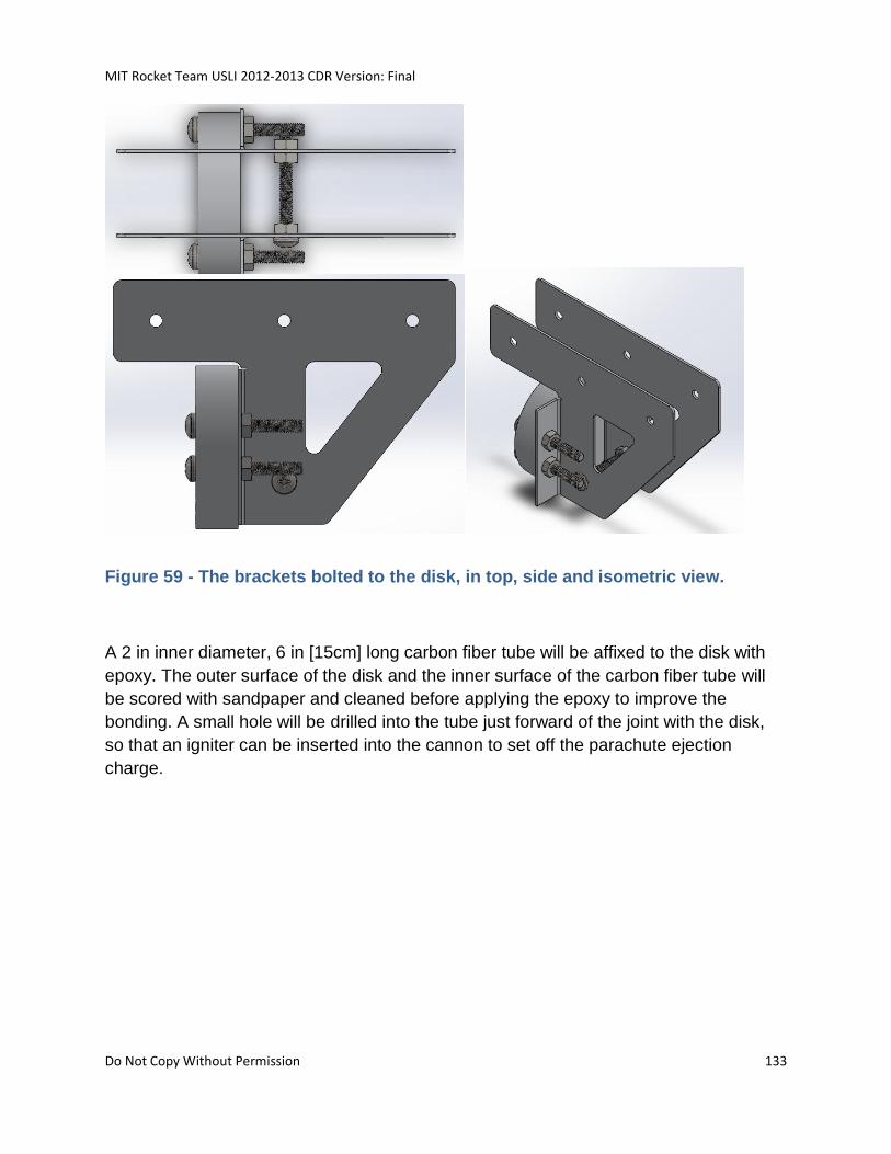
MIT Rocket Team USLI 2012-2013 CDR Version: Final
Do Not Copy Without Permission 133
Figure 59 - The brackets bolted to the disk, in top, side and isometric view.
A 2 in inner diameter, 6 in [15cm] long carbon fiber tube will be affixed to the disk with
epoxy. The outer surface of the disk and the inner surface of the carbon fiber tube will
be scored with sandpaper and cleaned before applying the epoxy to improve the
bonding. A small hole will be drilled into the tube just forward of the joint with the disk,
so that an igniter can be inserted into the cannon to set off the parachute ejection
charge.
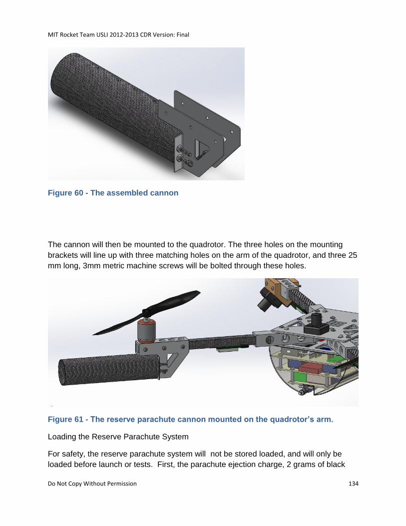
MIT Rocket Team USLI 2012-2013 CDR Version: Final
Do Not Copy Without Permission 134
Figure 60 - The assembled cannon
The cannon will then be mounted to the quadrotor. The three holes on the mounting
brackets will line up with three matching holes on the arm of the quadrotor, and three 25
mm long, 3mm metric machine screws will be bolted through these holes.
Figure 61 - The reserve parachute cannon mounted on the quadrotor’s arm.
Loading the Reserve Parachute System
For safety, the reserve parachute system will not be stored loaded, and will only be
loaded before launch or tests. First, the parachute ejection charge, 2 grams of black
MIT Rocket Team USLI 2012-2013 CDR Version: Final
Do Not Copy Without Permission 135
powder,will be attached to an electric igniter passhed through a small hole in the base
of the carbon fiber tube. The charge and igniter will be slid to the back of the tube, and
the igniter will be connected to the control circuit. . To protect the parachute from the
heat of the ejection charge, a 0.5 inch thick extruded polystyrene foam disk will be
packed into the tube before the parachute. Next, the parachute will be tied to a 3 meter
shock cord and folded. The folded parachute will be inserted into the tube, with the
shock cord hanging out the open end of the tube. Most of the shock cord will be coiled
into the tube, and about 10 in [25 cm] will be left free to tie off the parachute to the bolt
between the brackets. Then, a paper or light plastic cover will be taped on the end of
the tube. The cover will prevent debris from entering the tube and keep the parachute
from sliding out, but will be blown off if the parachute ejection charge is fired. The cover
will be colored bright orange to remine the ground crew to use caution around the
loaded parachute system. This process will then be repeated on the second parachute
cannon.
Figure 62 - Exploded view of the components packed into the reserve parachute
cannon
Control
A small microcontroller (Arduino Nano) will control the reserve parachute. The
microcontroller will monitor the output of the radio control receiverand a barometric
sensor. The electric igniters in the parachute ejection charges will be connected to a
MIT Rocket Team USLI 2012-2013 CDR Version: Final
Do Not Copy Without Permission 136
power supply through a transistor switched by one of the microcontroller’s digital output
pins.
Figure 63 - The reserve parachute igniter circuit
The microcontroller will enter an active mode after the quadrotor sabot opens. In active
mode, the microcontroller will apply current to the igniters if it detects a loss of signal on
the radio control receiver, or if it detects barometer readings which indicate that the
quadrotor is falling. The quadrotor may enter a failure mode in which it is falling at a
dangerous rate but is not under significant acceleration (examples: falling near terminal
velocity, weight slightly exceeds thrust for several minutes). Therefore it is useful to
examine the decent rate inferred from the barometer, instead of an accelerometer, to
determine if the quadrotor is falling. The reserve parachute system is designed to be
triggered by any of the following conditions:
1. The radio receiver loses signal for more than 5000 ms
2. The accelerometer reads an average acceleration of less than 2 m/s2 over the
last 1000 ms
3. The barometer indicates an average rate of decent greater than 20 m/s over the
last 5000 ms
4. The ground crew determines that the quadrotor is out of control, and manually
trigger the reserve parachute system by turning off their radio transmitter,
causing a loss of signal.
A simple simulation of the free-fall behavior of the quadrotor was used to inform the
choice of thresholds in the above conditions. The simulation uses the drag equation,
MIT Rocket Team USLI 2012-2013 CDR Version: Final
Do Not Copy Without Permission 137
and assumes the quadrotor has a Cd of 1 and a downward facing area of 0.04m2.
Rough predictions of the acceleration, velocity and position are plotted below.
Figure 64 - A rough prediction of the quadrotor’s free-fall kinematics
Testing
We will test ejecting the parachute upwards from a stationary platform on the ground to
determine whether the black powder charge is sufficient to properly eject the parachute.
The charge will be triggered by a remote ignition circuit, shields will be placed around
the system, and all personnel will be at least 30m away when the test occurs.
We will verify the control circuitry’s free-fall detection in a drop test. We will replace the
igniter with bright LEDs, and will package the control circuitry in a protective case. We
will then drop the package from a tall structure, and observe whether the LEDs flash on
during the fall.
5.1.12.4.3.2 SOFTWARE
The custom HALO software functions to be written on the BeagleBone in addition to
their parameters and outputs are defined below:
GetImages (camera#)
Takes a specific camera as a parameter and returns the image from that camera
MIT Rocket Team USLI 2012-2013 CDR Version: Final
Do Not Copy Without Permission 138
Signal Bus: TTL
Pins: Depends on camera number (), TX RX
P9.24 (D15, UART1_TXD); P9.26 (D16, UART1_RXD)
P9.21 (B17, UART2_TXD); P9.22 (A17, UART2_RXD)
P9.13 (U17, UART4_TXD); P9.11 (T17, UART4_RXD)
P8. 37 (U1, UART5_TXD); P8.38 (U2, UART5_RXD)
Convert: Hex signals to JPEG
Returns JPEG
CVStereo (IplImage1, IplImage2)
Takes two images as a parameter and returns a 3-d image
GetandSaveSensor ( )
Calls ReadRadioReciver ( ), Readmagnetometer ( ) , ReadAtmosphericData ( ),
ReadLangmuir ( ), and ReadEMF ( ) methods and then saves their data.
FindObject (3d-image)
Takes a 3-d image as an parameter (from the CV stereovision) and returns a 3d-
position
Return Array [double] X, Y, Z (meters)
FollowObject (3d-pos)
Takes a 3-d pos as a parameter, and calls CalculateDesiredPos ( ). Then calls
CommToAutoPilot ( )
CommToAutoPilot ( )
Sends RC commands to the autopilot.
TransmitSensorData ( )
Gets the saved sensor data and sends via radio them to the ground
Signal Bus: SPI
MIT Rocket Team USLI 2012-2013 CDR Version: Final
Do Not Copy Without Permission 139
Pins: USB UART0
PredictObjectPos ()
Finds the trajectory of the object it is following
Curve fit X, Y, Z as functions of time
Calculate time until separation distance (Z axis) is desired distance
Calculate X and Y after time has elapsed
*write equations and geometry*
CalculateDesiredPos ( )
Calls PredictObjectPos () and returns the next position to be in to continue
following the nosecone.
Customization for Auto-Pilot:
Dormant Phase ( )
Activated before launch. Nothing will occurs until the quad rotor is ejected from
the rocket
ArmFreefallDetector ( )
Activates the freefall detector. If freefall is detected for longer than a certain time,
the reserve chute will be released.
CheckFreefallDetector ( )
Checks the freefall detector against the other dectector
CheckBattery ( )
CheckUnfolding ( )
Checks to see that the quad rotor arms unfolded correctly. Mechanism TBD.
MIT Rocket Team USLI 2012-2013 CDR Version: Final
Do Not Copy Without Permission 140
CheckMotors ( )
Checks that motors are rotating (and not caught up in the parachute)
CutChute ( )
Will be called from the ground. The main chute will be cut.
ToggleRC ( )
The computer will switch to manual control using the RC inputs. It will also
ignore signals from the science payload (tracking of the nosecone)
ToggleScience ( )
The computer will switch control to the science payload. It will receive simulated
RC imputs from FollowObject ( )
getTouchInfo ( )
Gets the status of the physical touch sensor on the bottom of the quadcopter
5.1.12.4.4 CALIBRATION PROCEDURES
5.1.12.5 COMMUNICATIONS
Communications is done through a 3DR radio and Xbee Pro transceiver.
5.1.12.6 POWER AND PROPULSION
A direct drive brushless 830W Turnigy SK3 Motor with a 42 millimeter diameter was
chosen as it provides suitable thrust for its size. The motor will be positioned below the
propeller. The static thrust for the motor was calculated using www.ecalc.ch (good for
static thrust with an accuracy of about +/-10%); this resulted in a thrust of 6.5 lbs per
motor with a 7 minute flight time (with 4S, 6Ah LiPo per motor).
5.1.13 OVERVIEW: HALO
High Altitude Lightning Observatory
5.1.13.1 STRUCTURES
MIT Rocket Team USLI 2012-2013 CDR Version: Final
Do Not Copy Without Permission 141
The structure the suite of sensors is located on can be found in the quadrotor structures
overview section.
5.1.13.2 AVIONICS
A high level overview of the HALO avionics system and its interfaces can be found in
section 5.1.12.4.
5.1.13.2.1 COMMAND AND DATA HANDLING
5.1.13.2.1.1 HARDWARE
The HALO suite of sensors is located on the deployed quadrotor. As an experiment
designed to measure the effects of high altitude lightning on the surrounding
environment it consists of two categories of avionics systems: lightning detectors and
environmental sensors. The lightning detectors are comprised of a Hobby Boards
Lightning Detector and nearly spherical array of USB cameras (the same set used for
object tracking). A magnetic north sensor, triple axis magnetometer, ULF/VLF receiver,
custom EMF sensor, and custom Langmuir probe will encompass the set of
environmental sensors. Both avionics systems are integrated on a Beaglebone either
through a USB, SPI, or analog interface. The Beagle Board serves as the main payload
CPU that runs the payload software and handles science data collection. Science data
on the Beagle Board is saved internally and transferred to the SPRITE quadrotor
communication CPU via a SPI connection. HALO contains atmospheric sensors to
obtain local pressure and temperature values during quadrotor descent. A Beaglebone
acts as the sub-system’s CPU, records these values to a SD card, and transmits this
information via an Xbee Pro.
A custom Langmuir probe will be built to measure plasma energy and density. This
analog sensor’s design is based off of the design outlined Noah Warner’s 2001 Master’s
Thesis. (Warner, 2001) Using the Langmuir probe the plasma will be sampled for
intervals greater than 10 seconds to an accuracy of +/- 1 eV and +/- 1 x 10¹⁰ number of
particles/m3. This ensures that the energy and density requirement, as stated in the
project hypothesis, is being met and it ensures that a large sample is size taken. The 10
second window allows the sensor to capture short random variations in the data which
reduces random variation in the point estimates of the post processed data. To derive
the plasma properties the current and voltage outputted from the probe are sampled
and plotted with respect to each other. For the geometry of the resulting graph the ion
MIT Rocket Team USLI 2012-2013 CDR Version: Final
Do Not Copy Without Permission 142
and electron energy and density can be found. (Krehbiel, Brace, Theis, Cutler, Pinkus,
& Kaplan, 1980)
To capture the magnetic field strength, for independent variable verification, a
Honeywell (SS49E) linear Hall-effect sensor will be used. This IC is also an analog
sensor as it outputs a voltage proportional to the magnetic field strength with a 3
microsecond response time. A Hall-effect sensor was chosen over a magnetometer due
to ease of data collection and limitations in magnetic field sensing range. The chosen
sensor can operate within the field strength range of the project as it has a +/- 0.1 tesla
magnetic range with a 1.4mV/0.0001 tesla sensitivity. With an operating temperature of
-40 C to 100 C the sensor can function nominally given under the heat generated by the
coils. The hall sensor requires a 2.7 – 6.5 supply voltage so both it and the Langmuir
probe can be operated using a low voltage source of 5.5 volts. This power source can
be achieved from a 9 volt or 12 volt battery in series with a Texas Instrument 7805 5 volt
linear regulator
5.1.13.2.1.1.1 SENSORS
Name BMP085
Manufacture Adafruit
Vendor Adafruit
Part Number 391
Cost 19.95
Dimensions See B.O.M.
Weight See B.O.M.
Input Voltage 3-5V
Pressure Range 300-1100 hPa
Pressure Resolution 0.25m
Operational Temperature -40 to +85C
Temperature Accuracy +/- 2C
Description
Barometric pressure/temperature/altitude sensor
Name Lightning Detector
Manufacture Hobby Boards
Vendor Hobby Boards
Part Number LD4-R1-A
Cost 32.50
Dimensions See B.O.M.
Weight See B.O.M.
Input Voltage 9V
Range 50 miles with 24in antenna
Signal 1-wire
MIT Rocket Team USLI 2012-2013 CDR Version: Final
Do Not Copy Without Permission 143
Description
Can detect the electromagnetic pulse from a lightning discharge. Used conjunction with the other set of HALO sensors a correlation between lightning discharges and the state of the surrounding environment (particularly in regards to local electric field and emitted ULF/VLF waves) for various altitudes can be found.
Name Triple Axis Magnetometer Breakout – HMC5883L
Manufacture Sparkfun/Honeywell
Vendor Sparkfun
Part Number SEN-10530
Cost 14.95
Dimensions 0.7 x 0.7 in
Weight See B.O.M.
Input Voltage 2.3-3.4V
Sensor Resolution 5 milli-gauss
Operational Temperature -40 to +85C
Signal I2C
Description
Part of the HALO suite of sensors; it measures the local magnetic field. Once the sensor is calibrated for tilt and local magnetic field disturbances any significant changes to the magnetic field can be attributed to natural or artificial sources. More insight on lightning’s effect on the local magnetic field can be gained if the magnetometer is run at the same time as the lightning detectors.
Name Explorer E202 Natural Radio Receiver
Manufacture SISTEL
Vendor SISTEL
Part Number E202
Cost 299.55
Dimensions See B.O.M.
Weight See B.O.M.
Input Voltage 9V
Frequency Response 3Hz-10Hz and 120Hz-10kHz
Pressure Resolution 0.25m
Signal Signal output to PC
Description
Explorer E202 natural radio receiver
Name JPEG Color Camera
MIT Rocket Team USLI 2012-2013 CDR Version: Final
Do Not Copy Without Permission 144
Manufacture LinkSprite
Vendor Sparkfun
Part Number SEN-10061
Cost 49.95
Dimensions 32mm x 32mm
Weight 29.4g
Video Resolution 640x480p
Camera Angle 120 degrees
Signals TTL
Description
TTL Camera
5.1.13.2.1.1.2 DATA LOGGING AND COMPUTERS
Name BeagleBone
Manufacture BeagelBoard
Vendor Digikey
Part Number BB-BONE-000-ND
Cost 89
Dimensions 3.4 x 2.1 in
Weight See B.O.M.
Input Voltage 3-5V
Processor ARM Cortex –A8 700 MHz
Memory 256MB DDR RAM
Operating Systems Linux, WinCE
Signals Analog, SPI, UART, I2C, PWM, USB
Description
Serves as the main CPU for the HALO payload and suite of sensors. Runs camera tracking algorithms, saves incoming data and images, and sends telemetry to the Xbee to be transmitted to the ground station.
5.1.13.2.1.1.3 PLACEMENT AND MOUNTING
The placement of the avionics components is shown in Figure 65.
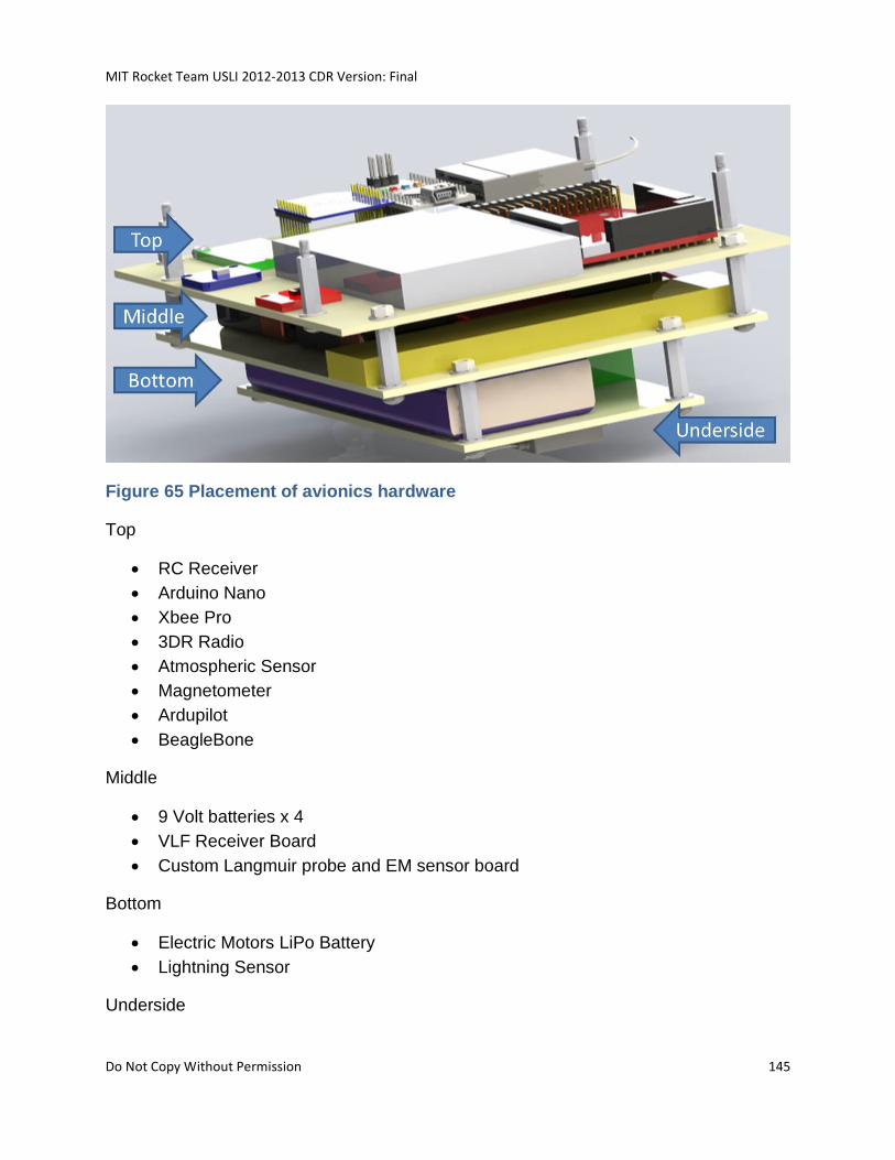
MIT Rocket Team USLI 2012-2013 CDR Version: Final
Do Not Copy Without Permission 145
Figure 65 Placement of avionics hardware
Top
RC Receiver
Arduino Nano
Xbee Pro
3DR Radio
Atmospheric Sensor
Magnetometer
Ardupilot
BeagleBone
Middle
9 Volt batteries x 4
VLF Receiver Board
Custom Langmuir probe and EM sensor board
Bottom
Electric Motors LiPo Battery
Lightning Sensor
Underside
MIT Rocket Team USLI 2012-2013 CDR Version: Final
Do Not Copy Without Permission 146
VLF Antenna
RC Receiver Antenna
5.1.13.2.1.1.4 REDUNDANCY
Telemetry and commands can be communicated to the ground by either the 3DR radio,
Xbee transceiver, or the RC receiver (for simple rotorcraft commands).
5.1.13.2.1.2 SOFTWARE
The custom HALO software functions to be written on the BeagleBone in addition to
their parameters and outputs are defined below:
ReadRadioReciver ( )
Returns radio receiver data
Signal Bus: ADC
Pins: P9.33 (C8, AN4)
Returns: Voltage
Convert: Voltage to Magnitude (dB)
Returns: double Magnitude (dB)
ReadMagnetometer ( )
Returns magnetometer data
Signal Bus: I2C
Pins: P9.17 (A16, I2C1_SCL); P9.18 (B16, I2C1_SDA)
Returns: Array of Hex Values
Convert: Hex Values to X, Y, and Z Magnitude (Tesla)
Returns: Array [double] X, Y, and Z Magnitude (Tesla)
ReadAtmosphericSensors ( )
Returns atmospheric sensor data
MIT Rocket Team USLI 2012-2013 CDR Version: Final
Do Not Copy Without Permission 147
Signal Bus: I2C
Pins: P9.19 (B17, I2C2_SCL); P9.20 (D18, I2C2_SDA)
Returns: Array of Hex Values
Convert: Hex Values to Pressure (Pa)
Returns: Array [double] X, Y, and Z Magnitude (Pa)
ReadLangmuir ( )
Returns Langmuir data
Signal Bus: ADC
Pins: P9.35 (A5, AIN6)
Returns: Voltage
Convert: Voltage to electric potential
Returns: electric potential (Volts)
ReadEMF ( )
Return EMF data
Signal Bus: ADC
Pins: P9.37 (B7, AIN2)
Returns: Voltage
Convert: Voltage to EMF
Returns: double EMF (Volts)
GetImages (camera#)
Takes a specific camera as a parameter and returns the image from that camera
Signal Bus: TTL
Pins: Depends on camera number (), TX RX
P9.24 (D15, UART1_TXD); P9.26 (D16, UART1_RXD)
MIT Rocket Team USLI 2012-2013 CDR Version: Final
Do Not Copy Without Permission 148
P9.21 (B17, UART2_TXD); P9.22 (A17, UART2_RXD)
P9.13 (U17, UART4_TXD); P9.11 (T17, UART4_RXD)
P8. 37 (U1, UART5_TXD); P8.38 (U2, UART5_RXD)
Convert: Hex signals to JPEG
Returns JPEG
5.1.13.2.2 CALIBRATION PROCEDURES
The calibration equations for the hall sensor will be derived based on the Helmholtz coil
testing. The MIT Space System’s Laboratory has a test stand in which the Helmholtz
current to magnetic field relationship has already been characterized. To find the
calibration equation, measure a range of magnetic field strengths from these coils with
the un-calibrated hall sensors. Plot the measured versus actual field strength and
Microsoft Excel and use the trend tool to find the linear relationship; this function is the
calibration equation. Calibrating the Langmuir probe utilizes a similar procedure.
Calibrate the un-calibrated probes against a calibrated probe measuring a particle
source. Again, to find the calibration equation plot the measured values versus the
values recorded by the calibrated probe in Microsoft Excel and use the trend tool.
5.1.13.2.3 DATA RETREIVAL AND PROCESSING
5.1.13.3 COMMUNICATIONS
Name Xbee Pro 60mW Wire Antenna – Series 1 (802.15.4)
Manufacture Digi
Vendor Sparkfun
Part Number WRL-08742
Cost 37.95
Dimensions
Weight
Input Voltage 3.3V
Data Rate 250kbps
Range 1 mile
Description
Used for transmitting data from the BeagleBone.
5.1.13.4 POWER
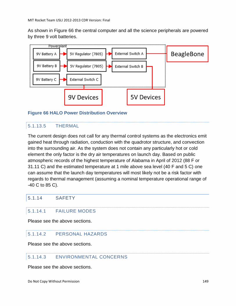
MIT Rocket Team USLI 2012-2013 CDR Version: Final
Do Not Copy Without Permission 149
As shown in Figure 66 the central computer and all the science peripherals are powered
by three 9 volt batteries.
Figure 66 HALO Power Distribution Overview
5.1.13.5 THERMAL
The current design does not call for any thermal control systems as the electronics emit
gained heat through radiation, conduction with the quadrotor structure, and convection
into the surrounding air. As the system does not contain any particularly hot or cold
element the only factor is the dry air temperatures on launch day. Based on public
atmospheric records of the highest temperature of Alabama in April of 2012 (88 F or
31.11 C) and the estimated temperature at 1 mile above sea level (40 F and 5 C) one
can assume that the launch day temperatures will most likely not be a risk factor with
regards to thermal management (assuming a nominal temperature operational range of
-40 C to 85 C).
5.1.14 SAFETY
5.1.14.1 FAILURE MODES
Please see the above sections.
5.1.14.2 PERSONAL HAZARDS
Please see the above sections.
5.1.14.3 ENVIRONMENTAL CONCERNS
Please see the above sections.
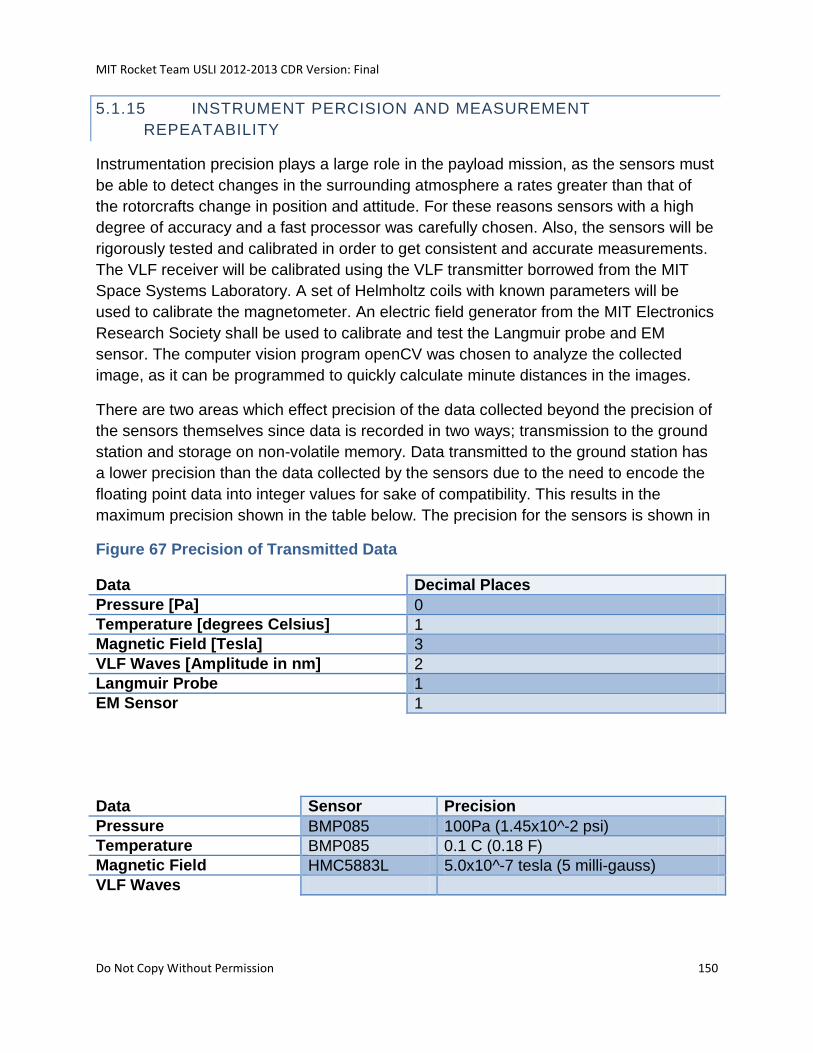
MIT Rocket Team USLI 2012-2013 CDR Version: Final
Do Not Copy Without Permission 150
5.1.15 INSTRUMENT PERCISION AND MEASUREMENT
REPEATABILITY
Instrumentation precision plays a large role in the payload mission, as the sensors must
be able to detect changes in the surrounding atmosphere a rates greater than that of
the rotorcrafts change in position and attitude. For these reasons sensors with a high
degree of accuracy and a fast processor was carefully chosen. Also, the sensors will be
rigorously tested and calibrated in order to get consistent and accurate measurements.
The VLF receiver will be calibrated using the VLF transmitter borrowed from the MIT
Space Systems Laboratory. A set of Helmholtz coils with known parameters will be
used to calibrate the magnetometer. An electric field generator from the MIT Electronics
Research Society shall be used to calibrate and test the Langmuir probe and EM
sensor. The computer vision program openCV was chosen to analyze the collected
image, as it can be programmed to quickly calculate minute distances in the images.
There are two areas which effect precision of the data collected beyond the precision of
the sensors themselves since data is recorded in two ways; transmission to the ground
station and storage on non-volatile memory. Data transmitted to the ground station has
a lower precision than the data collected by the sensors due to the need to encode the
floating point data into integer values for sake of compatibility. This results in the
maximum precision shown in the table below. The precision for the sensors is shown in
Figure 67 Precision of Transmitted Data
Data Decimal Places
Pressure [Pa] 0
Temperature [degrees Celsius] 1
Magnetic Field [Tesla] 3
VLF Waves [Amplitude in nm] 2
Langmuir Probe 1
EM Sensor 1
Data Sensor Precision
Pressure BMP085 100Pa (1.45x10^-2 psi)
Temperature BMP085 0.1 C (0.18 F)
Magnetic Field HMC5883L 5.0x10^-7 tesla (5 milli-gauss)
VLF Waves
MIT Rocket Team USLI 2012-2013 CDR Version: Final
Do Not Copy Without Permission 151
It is worth noting that the flight computer also logs data from the sensors connected to it
at their precision as this data is not transmitted and so does not need to be converted to
integer values for compatibility.
Given the changing nature of the atmosphere repeatability of data collection is
synonymous with reusability of the data collection hardware and by extension the
rotorcraft and rocket. To this extent all aspects of the rocket, rotorcraft and avionics
have been designed with reusability in mind.
5.1.16 EXPECTED FINAL DATA
Time stamped color images for each camera
Two sets of time stamped stereographic images
List of frames with a positive feature recognition (rocket)
List of frames with a positive feature recognition (ground)
Local electric field versus time
Local magnetic field versus time
Received VLF waves versus time
Local pressure versus time
Local temperature versus time
Number of detected lightning strikes versus time
5.1.17 DESIGN INTEGRITY
Design integrity is an important aspect to a project such as USLI. As such, the launch
vehicle has been designed using common design practices in high powered rocketry
and has also been influenced by the experience of the team.
A high level of integrity is expected of the quadrotor design as otherwise the science
payload will be left incapable of completing the mission. The integrity of the rotorcraft
design can be noted throughout the manufacturing, testing and analysis sections. The
beginning of the design process included ample use of SolidWorks and team meetings
with senior team members to ensure that all systems and subsystems will be of high
enough caliber and structural reliability to meet the requirements set by the mission.
5.1.17.1 PROPER USE OF MATERIALS
The structural elements in the vehicle are commonly used in high powered rocketry.
They include phenolic tubing wrapped in carbon fiber, fiberglass fins and a wooden
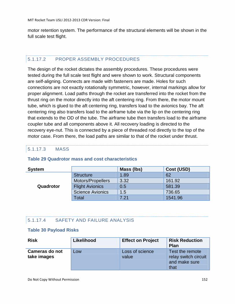
MIT Rocket Team USLI 2012-2013 CDR Version: Final
Do Not Copy Without Permission 152
motor retention system. The performance of the structural elements will be shown in the
full scale test flight.
5.1.17.2 PROPER ASSEMBLY PROCEDURES
The design of the rocket dictates the assembly procedures. These procedures were
tested during the full scale test flight and were shown to work. Structural components
are self-aligning. Connects are made with fasteners are made. Holes for such
connections are not exactly rotationally symmetric, however, internal markings allow for
proper alignment. Load paths through the rocket are transferred into the rocket from the
thrust ring on the motor directly into the aft centering ring. From there, the motor mount
tube, which is glued to the aft centering ring, transfers load to the avionics bay. The aft
centering ring also transfers load to the airframe tube via the lip on the centering ring
that extends to the OD of the tube. The airframe tube then transfers load to the airframe
coupler tube and all components above it. All recovery loading is directed to the
recovery eye-nut. This is connected by a piece of threaded rod directly to the top of the
motor case. From there, the load paths are similar to that of the rocket under thrust.
5.1.17.3 MASS
Table 29 Quadrotor mass and cost characteristics
System Mass (lbs) Cost (USD)
Quadrotor
Structure 1.89 62
Motors/Propellers 3.32 161.92
Flight Avionics 0.5 581.39
Science Avionics 1.5 736.65
Total 7.21 1541.96
5.1.17.4 SAFETY AND FAILURE ANALYSIS
Table 30 Payload Risks
Risk Likelihood Effect on Project Risk Reduction Plan
Cameras do not take images
Low Loss of science value
Test the remote relay switch circuit and make sure that
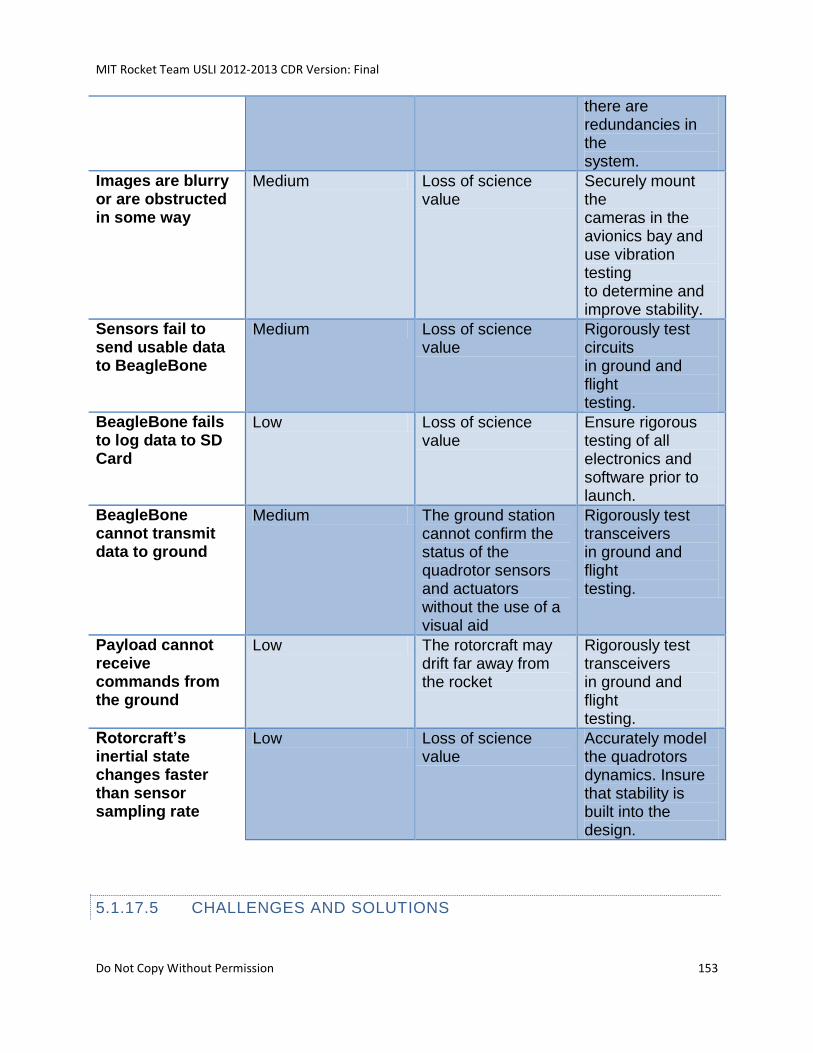
MIT Rocket Team USLI 2012-2013 CDR Version: Final
Do Not Copy Without Permission 153
there are redundancies in the system.
Images are blurry or are obstructed in some way
Medium Loss of science value
Securely mount the cameras in the avionics bay and use vibration testing to determine and improve stability.
Sensors fail to send usable data to BeagleBone
Medium Loss of science value
Rigorously test circuits in ground and flight testing.
BeagleBone fails to log data to SD Card
Low Loss of science value
Ensure rigorous testing of all electronics and software prior to launch.
BeagleBone cannot transmit data to ground
Medium The ground station cannot confirm the status of the quadrotor sensors and actuators without the use of a visual aid
Rigorously test transceivers in ground and flight testing.
Payload cannot receive commands from the ground
Low The rotorcraft may drift far away from the rocket
Rigorously test transceivers in ground and flight testing.
Rotorcraft’s inertial state changes faster than sensor sampling rate
Low Loss of science value
Accurately model the quadrotors dynamics. Insure that stability is built into the design.
5.1.17.5 CHALLENGES AND SOLUTIONS
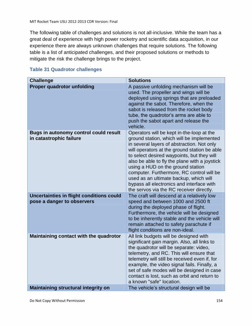
MIT Rocket Team USLI 2012-2013 CDR Version: Final
Do Not Copy Without Permission 154
The following table of challenges and solutions is not all-inclusive. While the team has a
great deal of experience with high power rocketry and scientific data acquisition, in our
experience there are always unknown challenges that require solutions. The following
table is a list of anticipated challenges, and their proposed solutions or methods to
mitigate the risk the challenge brings to the project.
Table 31 Quadrotor challenges
Challenge Solutions
Proper quadrotor unfolding A passive unfolding mechanism will be used. The propeller and wings will be deployed using springs that are preloaded against the sabot. Therefore, when the sabot is released from the rocket body tube, the quadrotor’s arms are able to push the sabot apart and release the vehicle.
Bugs in autonomy control could result in catastrophic failure
Operators will be kept in-the-loop at the ground station, which will be implemented in several layers of abstraction. Not only will operators at the ground station be able to select desired waypoints, but they will also be able to fly the plane with a joystick using a HUD on the ground station computer. Furthermore, RC control will be used as an ultimate backup, which will bypass all electronics and interface with the servos via the RC receiver directly.
Uncertainties in flight conditions could pose a danger to observers
The craft will descend at a relatively low speed and between 1000 and 2500 ft during the deployed phase of flight. Furthermore, the vehicle will be designed to be inherently stable and the vehicle will remain attached to safety parachute if flight conditions are non-ideal.
Maintaining contact with the quadrotor All link budgets will be designed with significant gain margin. Also, all links to the quadrotor will be separate: video, telemetry, and RC. This will ensure that telemetry will still be received even if, for example, the video signal fails. Finally, a set of safe modes will be designed in case contact is lost, such as orbit and return to a known "safe" location.
Maintaining structural integrity on The vehicle’s structural design will be
MIT Rocket Team USLI 2012-2013 CDR Version: Final
Do Not Copy Without Permission 155
landing performed with conservative safety margins, coupled with an aggressive test campaign to ensure that the airframe is capable of withstanding landing loading conditions. Furthermore, the legs of the craft will be reinforced with Kevlar in order to mitigate impact damage and vibration isolation will be used if necessary.
5.2 PAYLOAD CONCEPT FEATURES AND DEFINITION
5.2.1 CREATIVITY AND ORIGINALITY
The idea of a deploying a quadrotor with a rocket is not an entirely original idea;
however, the end goal of producing a cheap and reliable rotorcraft that can take data
while tracking a moving target is. Furthermore, by choosing a rocket deployment, and
keeping to a $5000 budget, it further allows for this technology to be applied to
situations where time and budget are controlling factors. This quick deployment and
relative low cost of operation would ideally suit the needs of search and rescue
operations, reconnaissance missions, and even rapid scientific data gathering missions.
5.2.2 UNIQUENESS AND SIGNIFICANCES
By doing these experiments, we hope to demonstrate a method which can be used to
validate high altitude lightning models and add to the knowledge body regarding
dynamic object tracking and communication by aerial vehicles. By doing this, we hope
to improve the areas of earth science and the usefulness of small UAVs in tactical
situations.
5.2.2.1 TECHNICAL AND SCIENTIFC RELEVANCE
Table 32 List of Relevant US Government SBIRs
Number Title Relevance to Project AI3R
A10-006 Missile Delivered UAV To be completed
N131-004 Automated Target Area Threat and Route Optimization
To be completed
N131-065 Automating Unmanned and To be completed
MIT Rocket Team USLI 2012-2013 CDR Version: Final
Do Not Copy Without Permission 156
Manned Sensor Performance in Demanding Tactical Environments
S1.08 In Situ Airborne, Surface, and Submersible Instruments for Earth Science
To be completed
SB131-007 Remote Sensing for Electric and Gravity Fields
To be completed
AF131-137 Very Low Frequency Receiver front end with high sensitivity and frequency selectivity
To be completed
A13-027 Vehicle Spacing Determination and Display In Low Visibility Conditions
To be completed
A12-119 Optical Communications for Control of Unmanned Ground Vehicles
To be completed
5.2.3 SUITABLE LEVEL OF CHALLENGE
There are many challenges associated with the science mission the MIT Rocket Team
has chosen to attempt this year. First and foremost the task of deploying a quadrotor
from a rocket is especially challenging. Integrating a suit of sensors into an autonomous
UAV is not easy feat, especially when the craft has to implement object tracking
algorithms in real-time.
Because of the significance of this project and the difficulties we expect to face, we
believe that this project is more than adequate for a challenging for this year’s
competition.
5.3 SCIENCE VALUE
5.3.1 SCIENCE PAYLOAD OBJECTIVES
There are two different aspects to the payload, each with their own objectives; the
requirements for HALO and demonstration of object tracking/object recognition in
dynamic environments during rotorcraft flight. The payload objectives relating to the
HALO suite of sensors are to log atmospheric pressure, temperature and magnetic field
MIT Rocket Team USLI 2012-2013 CDR Version: Final
Do Not Copy Without Permission 157
strength along with electric potential and VLF wave data at 5 second intervals. The
payload objectives relating to improving information acquisition, processing, and
transmission on and between mobile targets in an dynamic environment is to complete
the flight (visually locating and tracking the rocket) solely using the software installed on
the onboard processors without having to revert to back up manual control.
5.3.2 PAYLOAD SUCCESS CRITERIA
The data logging and sensors shall be deemed successful if the payload obtains and
logs atmospheric pressure, temperature, and magnetic field strength along with
received VLF wave, electric field strength, lightning strike count data, and images at a
maximum of 5 second intervals. It shall be deemed a success regardless if the data is
able to be transmitted to the ground.
Fulfilling the HALO payload requirement successfully shall also demonstrate the
flexibility in the quadrotor design.
If the quadrotor successfully visually tracks the rocket, demonstrates ground target
recognition, and lands in a state fit for reusability, without resorting to use of the back-up
manual flight control then this will demonstrate a successful ability of a rotorcraft to
tracking track moving targets while relaying information to a user (if communication to
the ground is achieved).
5.3.3 EXPERIMENTAL LOGIC, APPROACH, AND METHOD OF
INVESTIGATION
By using a science payload in a descending rotorcraft, atmospheric measurements
presented in section 5.1.16 will be collected. The science payload will be contained
inside built-in compartments in the fuselage, preventing thrashing of instruments from
launch initiation to landing of rotorcraft.
To obtain such data, all the sensors will be turned on just prior to launch and
measurements will be recorded at 5-second intervals during launch and decent within
target area. Using a rotorcraft to carry a science payload of multiple sensors and
accurately obtain such data will provide a more efficient means for obtaining such data.
Additionally, the telemetry devices inside the rotorcraft will allow for safe operation of
the vehicle via a pilot at the ground station. A single mission by a rotorcraft with such
MIT Rocket Team USLI 2012-2013 CDR Version: Final
Do Not Copy Without Permission 158
science payload gathers data at varying altitudes effectively and efficiently, relative to
other means of acquiring such data.
The goal of the rotorcraft is also to demonstrate the capability of a quadrotor to track a
moving target in a dynamic environment. This will be achieved by having stability control
on the rotorcraft such that it is able to maintain straight and level flight, perform
controlled turn and land safely with no user input. Combining this with an appropriately
designed user interface, this should be sufficiently automated that it can be controlled
by a person with absolutely no flying experience.
5.3.4 TEST MEASUREMENTS, VARIABLES, AND CONTROLS
Testing and verification of the avionics occurs in three distinct phases: ground testing,
on a commercially available quadrotor and lastly on the final quadrotor, thus enabling
ground testing shall consist of validating the correct operation of all hardware and
sensors in a non-critical environment. The testing on the test aircraft serves to verify
that the subsystems within the avionics system work as expected in flight case and to
validate changes made to the flight computer hardware and software for the purposes of
the competition. The flight testing on the quadrotor is to demonstrate the avionics
system is able to function correctly in its intended flight configuration and importantly,
that is it capable of recovery after deployment from the rocket.
5.3.4.1 PHASE ONE
First, the HALO sensors and single-board computer will be configured and tested in a
laboratory setting to ensure that our software can properly read data from the sensors.
We will attempt to read data from each sensor individually, and verify that the expected
readings are produced. Tests at this stage include reading data from the Langmuir
probes, and verifying that our stereo vision cameras and software can produce depth
images of sufficient accuracy.
Next we will integrate the sensors together to identify any interferences within the
sensing system. Example conflict to test for include noise on the EMF sensors caused
by currents flowing to the other sensors, and the effect of the processor time spent
performing computer vision operations on the sampling rate achievable on the other
sensors.
5.3.4.2 PHASE TWO
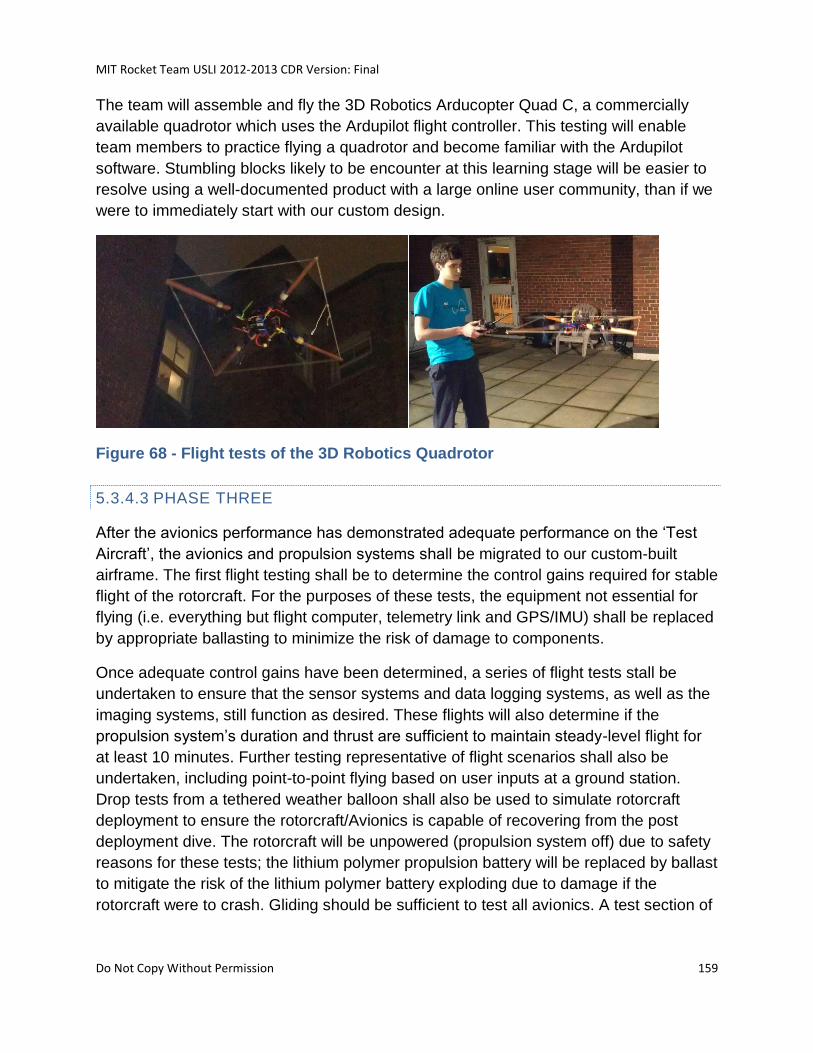
MIT Rocket Team USLI 2012-2013 CDR Version: Final
Do Not Copy Without Permission 159
The team will assemble and fly the 3D Robotics Arducopter Quad C, a commercially
available quadrotor which uses the Ardupilot flight controller. This testing will enable
team members to practice flying a quadrotor and become familiar with the Ardupilot
software. Stumbling blocks likely to be encounter at this learning stage will be easier to
resolve using a well-documented product with a large online user community, than if we
were to immediately start with our custom design.
Figure 68 - Flight tests of the 3D Robotics Quadrotor
5.3.4.3 PHASE THREE
After the avionics performance has demonstrated adequate performance on the ‘Test
Aircraft’, the avionics and propulsion systems shall be migrated to our custom-built
airframe. The first flight testing shall be to determine the control gains required for stable
flight of the rotorcraft. For the purposes of these tests, the equipment not essential for
flying (i.e. everything but flight computer, telemetry link and GPS/IMU) shall be replaced
by appropriate ballasting to minimize the risk of damage to components.
Once adequate control gains have been determined, a series of flight tests stall be
undertaken to ensure that the sensor systems and data logging systems, as well as the
imaging systems, still function as desired. These flights will also determine if the
propulsion system’s duration and thrust are sufficient to maintain steady-level flight for
at least 10 minutes. Further testing representative of flight scenarios shall also be
undertaken, including point-to-point flying based on user inputs at a ground station.
Drop tests from a tethered weather balloon shall also be used to simulate rotorcraft
deployment to ensure the rotorcraft/Avionics is capable of recovering from the post
deployment dive. The rotorcraft will be unpowered (propulsion system off) due to safety
reasons for these tests; the lithium polymer propulsion battery will be replaced by ballast
to mitigate the risk of the lithium polymer battery exploding due to damage if the
rotorcraft were to crash. Gliding should be sufficient to test all avionics. A test section of
MIT Rocket Team USLI 2012-2013 CDR Version: Final
Do Not Copy Without Permission 160
the rocket body tube will be hung from a balloon platform attached to the weather
balloon.
The rotorcraft will be packed into the sabot, and the sabot will be placed in the body
tube and connected to a radio controlled remote triggering/dropping device. The balloon
will be raised and tethered at an altitude of approximately 200 ft; this altitude should be
sufficient for full rotorcraft deployment, while restricting the safety radius needed to be
cleared of personnel on the ground to a reasonable value. Then the sabot will be
dropped under drogue parachute, and the rotorcraft will deploy. These tests shall be
performed with ballast instead of non-essential electronic components. This ballast will
be placed in such proportions and arrangements to maintain the center of mass of the
rotorcraft, providing sufficiently accurate mission conditions for the rotorcraft.
5.3.5 RELEVANCE OF EXPECTED DATA
The data collected is vital for the analysis of the systems and subsystems in
determining any necessary changes to the design of the rotorcraft, or to any instruments
and power devices. Accuracy of the data is also significant in that variations in the state
of the craft can lead to system instability..
Effectively, all data on the stability lift and drag forces for the propellers, arms, and the
assembled body must be accurate to determine the necessary attitude of the vehicle to
achieve specific tasks, such as steady-level flight, and landing.
The various measurements of the atmosphere will be gathered, organized and analyzed
to study changes in the atmosphere with changes in altitude, changes in amount of
atmosphere between the payload and ground, and changes in level of atmosphere
between the payload and space. This will provide real data, to contrast to theoretical
data predicting such qualities of the atmosphere based on location, altitude, and density
of the air.
Electronic measuring devices, computing components, and cameras can be greatly
affected by variables such as pressure, temperature, and vibrations; appropriate
knowledge of such variables can allow for proper preparation for objects entering such
conditions.
5.3.6 ACCURACY AND ERROR ANALYSIS
Accurate data provides information about atmospheric conditions to people, giving
realistic data for the analysis and design of different potential aerial mechanisms. Such
MIT Rocket Team USLI 2012-2013 CDR Version: Final
Do Not Copy Without Permission 161
data will also allow for scientific groups to consider the protection necessary for
instruments of varying sensitivity to cosmic electromagnetic radiation, that are planned
on being deployed at varying altitudes. Devices and forces can be greatly affected by
variables such as pressure, temperature, relative humidity, solar irradiance, and UV
radiation; appropriate knowledge of such variables can allow for proper preparation for
objects entering such conditions. A minimal sampling time interval was chosen to
reduce the likelihood of recording outlier values as nominal data by increasing the
sampling size taken over a specific range of parameters and independent variables. To
confirm the accuracy of the sensors, all sensors will be calibrated based on the methods
outlined in section 5.1.13.2.2. During the experiment at least two hall sensors and two
Langmuir probes will be use simultaneously. This adds redundancy to the data
collection system and allows each sensor to verify it neighbor’s output.
5.3.7 PRELIMINARY EXPERIMENT PROCESS PROCEDURES
• Individually test all sensors for temperature, pressure, relative humidity, solar
irradiance, and UV radiation (primary and back-up sensors).
o Pressure can be tested in a wind tunnel with a known dynamic pressure
o Temperature probes can be tested at room temperature, and outside ambient
temperature, which will range from 30 °F to 60 °F, at time of anticipated testing
• Determine mass of all instruments, avionics, and power devices
• Estimate mass of rotorcraft body materials
• Identify a suitable propulsion system and battery for device powering
• Using computational software, Excel and MATLAB, verify calculations for expected
parameters and requirements of the rotorcraft.
• Using CAD software, model rotorcraft with appropriate dimensions and parts.
• Use flight simulation software to determine flight patterns of rotorcraft
• Develop mission success criteria
MIT Rocket Team USLI 2012-2013 CDR Version: Final
Do Not Copy Without Permission 162
o All data accurately acquired and stored properly
o Still photographs acquired at SMD prescribed intervals
o Communication between payload and ground station seamless
o Semi-autonomous navigation capable of navigating to command coordinates
o Safe landing of rocket and tethered pieces with use of parachutes
o Safe landing of rotorcraft, employing protective underside coat
• Ensure rocket, rotorcraft and other equipment are reusable after each mission
5.4 SAFETY AND ENVIRONMENT (PAYLOAD)
5.4.1 IDENTIFICATION OF SAFETY OFFICERS
Please refer to safety officer information in previous sections.
5.4.2 SAFETY ANALYSIS
Please refer to payload safety analysis information in previous sections.
5.4.3 ANALYSIS OF FAILURE MODES AND MITIGATIONS
Please refer to payload failure mode analysis in previous sections.
5.4.4 PERSONAL HAZARDS
A listing of personnel hazards and evidence of understanding of safety hazards of the
payload is provided in the sections below.
5.4.4.1 SAFETY CHECKLIST
Please refer to system safety checklist information in rocket/vehicle section.
5.4.4.2 SAFETY PERCAUTIONS
MIT Rocket Team USLI 2012-2013 CDR Version: Final
Do Not Copy Without Permission 163
In order to assure safe and successful operations concerning the payload, a checklist
must be followed. In order to reduce personnel hazards the following precautions must
be taken:
• Avoid standing in the plane of the propeller when rotorcraft propulsion system is
on.
• Do not try to catch the rotorcraft during landing.
• Make sure all relevant testing (reference checklist) has been completed prior to
attempting a flight test.
• Make sure the checklist is followed and all steps are completed properly in a
thorough, workmanlike manner to assure mission success.
Lithium Polymer Battery Hazards and Procedures:
• Always charge lithium polymer batteries with a balancer. Out of balance packs
can explode.
• Never over-discharge a lithium polymer battery (below 2.7V per series cell).
• Never attempt to charge a lithium polymer battery if it looks bloated, damaged,
over discharged (below 2.7V per series cell). Damaged packs can explode.
• Never leave a lithium polymer battery unattended while charging.
• Always charge lithium polymer batteries on a non-flammable surface and away
from flammables.
• Take extreme caution around the rotorcraft in the case of a crash. The pack may
explode if damaged.
• Never discharge a lithium polymer battery at more than the published discharge
rate. The pack may explode if discharged too quickly.
5.4.4.3 TOOL USE INJURY POTENTIALS AND MITIGATIONS
Please refer to this item in the rocket/vehicle section.
5.4.4.4 SAFETY CODES
Please refer to this item in the rocket/vehicle section.
5.4.4.5 HAZARDS RECOGNITION
Please refer to this item in the rocket/vehicle section.
5.4.5 ENVIRONMENTAL CONCERNS
MIT Rocket Team USLI 2012-2013 CDR Version: Final
Do Not Copy Without Permission 164
All waste materials will be disposed of using proper trash receptacles
Consideration of environmental ramifications will be made regarding applicable
activities
The following list of materials has been identified as potentially hazardous:
o Aeropoxy 2032 Epoxy Resin
o Aeropoxy 3660 Hardener
o Lithium Polymer Batteries
6 SAFETY PLAN
6.1 PROCEDURES FOR NAR/TRA PERSONNEL TO PERFORM
The NAR/TRA mentors or a student team member that is NAR/TRA certified to the level
required will be responsible for all motor handling operations. This includes purchase,
storage, transportation and use at the launch site. They will be responsible for assembly
of the motor and possession of it until it is installed in the rocket. They will also officially
be the owner of the rocket, as is required for insurance purposes.
The NAR/TRA mentors or certified student team members will be responsible for
overseeing hazardous materials operations and handling.
Although it is not required by NAR/TRA rules that they perform operations regarding
non-motor related hazardous materials, they will generally be more informed and
experienced with the handling of ejection charges and igniters, and thus will either
perform operations involving hazardous materials or closely supervise them all usage of
hazardous materials.
6.2 HAZARD RECOGNITION AND ACCIDENT AVOIDANCE
Students will be briefed on hazard recognition and accident avoidance at points in time
that are relevant to associated hazards. MIT’s EHS (Environmental Health and Safety)
lab guidelines will be referenced prior to any activities that may involve hazard. These
documents are available on the EHS’s website (http://ehs.mit.edu).
The lab also has a dedicated EHS representative who is part of the team, who will
ensure EHS guidelines are followed. Prior to launch activities, specifically the scale test
launch, the full scale test launch, and the launch in Huntsville, the team members
attending will be briefed via a Power Point Presentation covering the hazards of high
power rocket launch activities, range safety codes (NFPA and NAR/TRA Safety codes-
see Appendix), and standard procedures and etiquette at launches. The NAR/TRA
MIT Rocket Team USLI 2012-2013 CDR Version: Final
Do Not Copy Without Permission 165
mentors or team members that are sufficiently experienced will perform these briefings.
All pertinent safety documents, including the safety presentations, will be available on
the team website for ease of reference.
6.3 OUTLINE OF HAZARD RECOGNITION BRIEFING
The Hazards Recognition Briefing PowerPoint Presentation will be given prior to
commencing rocket construction. It will cover accident avoidance and hazard
recognition techniques, as well as general safety.
1) General
a) Always ask a knowledgeable member of the team if unsure about:
a. Equipment
b. Tools
c. Procedures
d. Materials Handling
e. Other Concerns
b) Be cognizant of your own actions and those of others
a. Point out risks and mitigate them
b. Review procedures and relevant MSDS before commencing potentially
hazardous actions
c) Safety Equipment
a. Only close-toed shoes may be worn in the lab
2) Chemicals
a. The following are risks of chemical handling:
i. Irritation of skin, eyes, and respiratory system from contact and/or
inhalation of hazardous fumes.
ii. Secondary exposure from chemical spoils
iii. Destruction of lab space
b. Ways to mitigate these risks:
MIT Rocket Team USLI 2012-2013 CDR Version: Final
Do Not Copy Without Permission 166
i. Whenever using chemicals, refer to MSDS sheets for proper
handling
ii. Always wear appropriate safety gear
iii. Keep work stations clean
iv. Keep ventilation pathways clear
v. Always wear appropriate clothing
3) Equipment and Tools
a. The following are risks of equipment and tool handling:
i. Cuts
ii. Burning
iii. General injury
b. Ways to mitigate these risks: 10
i. Always wear appropriate clothing, e.g. closed-toe shoes
ii. Always wear appropriate safety equipment
iii. Always ask if unsure
iv. Err on the side of caution
4) Composites Safety
a. Carbon fiber, fiberglass, epoxy, and other composite materials require
special care when handling.
b. The following are risks of composites handling:
i. Respiratory irritation
ii. Skin irritation
iii. Eye irritation
iv. Splinters
v. Secondary exposure
MIT Rocket Team USLI 2012-2013 CDR Version: Final
Do Not Copy Without Permission 167
c. Ways to mitigate these risks:
i. Always wear facemasks and respirators when sanding, cutting,
grinding, etc.
ii. Always wear gloves when handling pre-cured composites
iii. Always wear goggles when handling composites
iv. Always wear puncture-resistant gloves when handling post-
cured composites
v. A dust-room has been constructed, as per MIT EHS guidelines,
specifically for the handling of composite materials
d. No team member will handle carbon fiber until properly trained
6.4 PRE-LAUNCH BRIEFING
The pre-launch briefing will include an overview of the hazards of high-power rocket
launch activities, range safety codes (NFPA and TRA/NAR Safety codes – see
Appendix), and standard procedures and etiquette at launches.
6.5 CAUTION STATEMENTS
Caution statements will be printed into all plans, procedures, and other working
documents that are related to risky activities. The documents include, but are not limited
to: checklists, operating procedures, lay-up procedures, and chemical handling
procedures. MSDS for all materials used in the lab will be available in the lab and on the
team website. See Appendix for a list of all relevant MSDS.
6.6 COGNIZANCE OF FEDERAL, STATE, AND LOCAL LAWS
REGARDING ROCET LAUCNH AND MOTOR HANDLING
The safety officer for the team will brief the team in a meeting regarding unmanned
rocket launches and motor handing. This will be in addition to the pre-launch briefings.
The following will be covered in this briefing:
MIT Rocket Team USLI 2012-2013 CDR Version: Final
Do Not Copy Without Permission 168
1. Federal Aviation Regulations 14CFR, Subchapter F, Part 101, Subpart C -
Amateur Rockets
2. 14CFR Part 55 – The Handling and use of Low-Explosives (Ammonium
Perchlorate Rocket Motors, APCP) and Fire Prevention (Note: As of Judge
Reggie B. Walton’s March 16, 2009 Ruling, APCP is no longer an explosive and
thus must not be sold and handled as such).
3. NFPA1127 – Code for High Power Rocket Motors
* See Appendices II and III
Each team member is required to understand and abide by the safety information in the
Student Safety Agreement, including the NAR safety code for high-powered rocketry
and key USLI safety regulations. This information will also be posted on the project
webpage in the Safety and Mission Assurance section.
6.7 PURCHASING AND HANDING ROCKET MOTORS
The motor casing and reload(s) will be purchased online by one of our Level 2 or Level
3 certified members. Level 2 and Level 3 members will also be the only ones permitted
to handle the motor reload(s), which will be stored in a specified and dedicated location
in the MIT Rocket Team’s lab fire-safety cabinet. The safety officer will make sure the
reload(s) are properly stored and, when required, transported in an appropriate
container. The safety officer will oversee all building of reload(s) and loading of rocket
motor(s).
6.8 TRANSPORTATION OF ROCKET TO HUNSTVILLE
In light of the recent ruling regarding APCP’s status as an explosive, the only federal
regulations pertaining to the control of rocket motors are those regarding commercial
transportation of motors (DOT) and NFPA regulations. The motors will be transported
either via car or shipped directly from a vendor to a designated location in Huntsville
prior to the launch. They will only be handled by our certified team members or a
certified NAR/TRA mentor. Given that we are not in commerce, travelling with them via
car requires no special permits other than a NAR/TRA certification.
6.9 SAFETY AGREEMENT
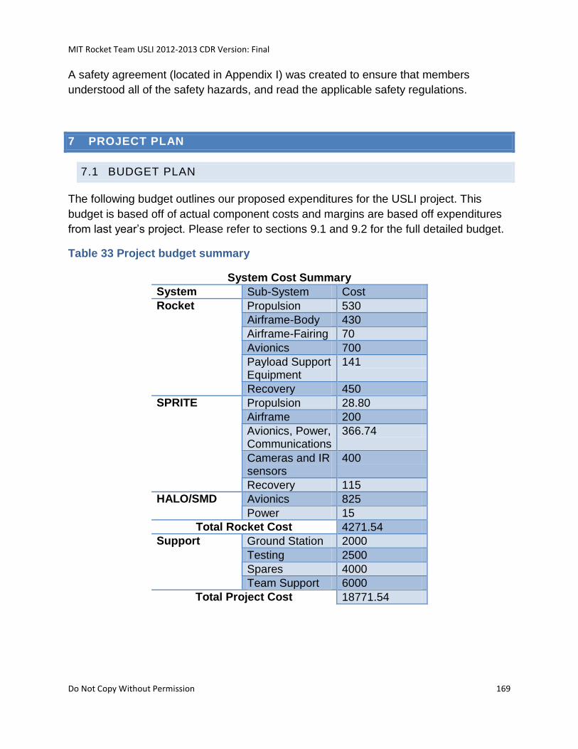
MIT Rocket Team USLI 2012-2013 CDR Version: Final
Do Not Copy Without Permission 169
A safety agreement (located in Appendix I) was created to ensure that members
understood all of the safety hazards, and read the applicable safety regulations.
7 PROJECT PLAN
7.1 BUDGET PLAN
The following budget outlines our proposed expenditures for the USLI project. This
budget is based off of actual component costs and margins are based off expenditures
from last year’s project. Please refer to sections 9.1 and 9.2 for the full detailed budget.
Table 33 Project budget summary
System Cost Summary
System Sub-System Cost
Rocket Propulsion 530
Airframe-Body 430
Airframe-Fairing 70
Avionics 700
Payload Support Equipment
141
Recovery 450
SPRITE Propulsion 28.80
Airframe 200
Avionics, Power, Communications
366.74
Cameras and IR sensors
400
Recovery 115
HALO/SMD Avionics 825
Power 15
Total Rocket Cost 4271.54
Support Ground Station 2000
Testing 2500
Spares 4000
Team Support 6000
Total Project Cost 18771.54
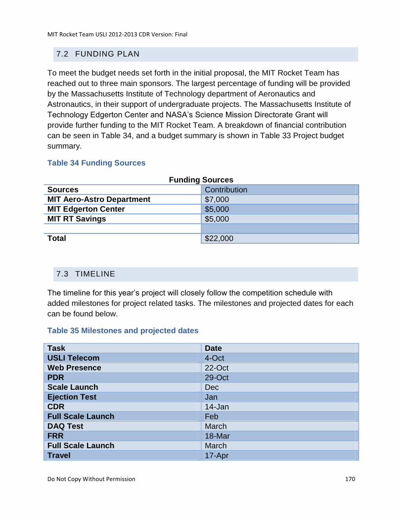
MIT Rocket Team USLI 2012-2013 CDR Version: Final
Do Not Copy Without Permission 170
7.2 FUNDING PLAN
To meet the budget needs set forth in the initial proposal, the MIT Rocket Team has
reached out to three main sponsors. The largest percentage of funding will be provided
by the Massachusetts Institute of Technology department of Aeronautics and
Astronautics, in their support of undergraduate projects. The Massachusetts Institute of
Technology Edgerton Center and NASA’s Science Mission Directorate Grant will
provide further funding to the MIT Rocket Team. A breakdown of financial contribution
can be seen in Table 34, and a budget summary is shown in Table 33 Project budget
summary.
Table 34 Funding Sources
Funding Sources
Sources Contribution
MIT Aero-Astro Department $7,000
MIT Edgerton Center $5,000
MIT RT Savings $5,000
Total $22,000
7.3 TIMELINE
The timeline for this year’s project will closely follow the competition schedule with
added milestones for project related tasks. The milestones and projected dates for each
can be found below.
Table 35 Milestones and projected dates
Task Date
USLI Telecom 4-Oct
Web Presence 22-Oct
PDR 29-Oct
Scale Launch Dec
Ejection Test Jan
CDR 14-Jan
Full Scale Launch Feb
DAQ Test March
FRR 18-Mar
Full Scale Launch March
Travel 17-Apr
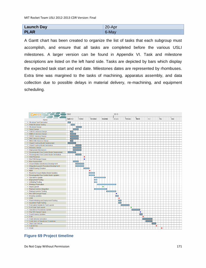
MIT Rocket Team USLI 2012-2013 CDR Version: Final
Do Not Copy Without Permission 171
Launch Day 20-Apr
PLAR 6-May
A Gantt chart has been created to organize the list of tasks that each subgroup must
accomplish, and ensure that all tasks are completed before the various USLI
milestones. A larger version can be found in Appendix VI. Task and milestone
descriptions are listed on the left hand side. Tasks are depicted by bars which display
the expected task start and end date. Milestones dates are represented by rhombuses.
Extra time was margined to the tasks of machining, apparatus assembly, and data
collection due to possible delays in material delivery, re-machining, and equipment
scheduling.
Figure 69 Project timeline
MIT Rocket Team USLI 2012-2013 CDR Version: Final
Do Not Copy Without Permission 172
7.4 COMMUNITY SUPPORT PLAN
7.4.1 EXPERTISE
The MIT Rocket Team has reached (and will continue to) out rocket enthusiasts via
networking events, on/off campus event, local rocket launches, and campus advertising.
7.4.2 EQUIPMENT/SUPPLIES
The MIT Rocket Team has strong ties with the Department of Aerospace Engineering
and the MIT Space Systems Laboratory. Often mechanical tools, equipment, or
fasteners can be borrowed from department facilities upon permission. The Space
System Laboratory is a great resource for the team in obtaining electrical hardware or
electrical measurement systems. The team will work hard to continue the excellent
relationship between the students and the faculty members in charge of these labs and
resources. Machining and assembly of the apparatus will respectively take place in the
AeroAstro machine shop and the Gelb work area. These locations are normally open to
students from 9:00am to 5:00pm; however, specific work in the Wright Brothers Wind
Tunnel will require extra assistance from AeroAstro personal. The availability of
AeroAstro members and equipment will have to be scheduled near the beginning of the
spring semester.
7.4.3 MONETARY DONATIONS
In the beginning of winter the team contacts companies and organizations and ask
whether or not they would like to sponsor out team’s activities for the year.
7.4.4 SERVICES
The team is in the process of expanding the list of testing facilities that out members
have access to. The executive members of the team are currently in contact with faculty
members regarding the potential use of the Aerospace Blast chamber.
7.4.5 ADVERTISEMENTS
The MIT Rocket Team makes full use of the advertisement opportunities available on
the MIT Campus. These include multimedia ads, flyers, posters, updates on official
campus wide social media networks, and ads in the school newspaper. We are looking
forward to contacting local news organizations once larger events in the community are
MIT Rocket Team USLI 2012-2013 CDR Version: Final
Do Not Copy Without Permission 173
scheduled, such as our Winter MIT Rocket Launch Event. Images of advertisements
can be found in section 7.4.5.
7.4.6 PARTNERS WITH SCHOOLS
Partner ships exist with the MIT Rocket Team and the rocket organization from Boston
University. There exists an ongoing project where the team has agreed to build a rocket
to house their custom hybrid engine upon completion of testing. We are also looking to
open up communication with Harvard University as they have a few new programs
which focus on rockery in the local area.
7.4.7 PARTNERS WITH INDUSTRY
The team plans to further its partnership with the local aerospace company Aurora
Flight Sciences. Last year we gave presentations, demos, and lab tours to a TARC
group which was lead by the General Manager of the Cambridge branch of Aurora. We
plan to email the general manager to set up future event such as these and to also seek
the possibility of monetary sponsorships or potential project opportunities.
7.5 MAJOR PROGAMMATIC CHALLENGES AND SOLUTIONS
The current major programmatic challenge is that the team lack experienced members.
Yet, because of the large influx of new members this problem can be overcome through
teaching the basic principles (including hands-on work) of high power rocketry to new
members throughout the academic year.
7.6 PROJECT SUSTAINABILITY PLAN
7.6.1 AQUIRING AND MAINTAINING PARTNERSHIPS
7.6.2 ENGAGING STUDENTS IN ROCKETRY
Engaging students in rocketry is discussed in much greater detail in the outreach plan
section; however, the team
7.6.3 PARTNERS IN INDUSTRY/COMMMUNITY
In addition to our partners at the MIT Museum and Aurora Flight Sciences the tea is
trying to expand the number of partners in the local community. Our path forward
involves increasing are community involvement through public events.
MIT Rocket Team USLI 2012-2013 CDR Version: Final
Do Not Copy Without Permission 174
7.6.4 RECRUITMENT OF STUDENTS
Like all official MIT student organizations the MIT Rocket Team has a large recruitment
drive in the beginning of the year which brings in 10 to 15 new members. Team
membership is open throughout the year and members are encouraged to invite their
friends/peers over for meetings or build sessions.
7.6.5 FUNDING SUSTAINABILITY
As long as the team remains active it has a stable and guaranteed source of founding.
The largest portion comes from the Department of Aerospace Engineering which gives
the team around $10,000 annually. If financial needs still aren’t meet then the team
seeks out funding from MIT sources such as GEL, and FinBoard.
7.7 OUTREACH PLAN AND EDUCATIONAL ENGAGEMENT
7.7.1 PURPOSE OF COMMUNITY OUTREACH
Our goal as active members of our surrounding community is to extend our knowledge
and interests to the younger population of the Greater Boston Area. To this end, we
have organized three community events that will target middle school through high
school students with the purpose of promoting higher education through mentoring
students and sparking interest for the arts and sciences. In the spirit of the USLI
competition, these events will focus on rocketry, including its history and inner workings,
to inspire the youth that they are capable of performing rocket science.
7.7.2 CURRENT SCHEDULE
The team plans to hold four community outreach events over the next few months to
inspire and educate the general public about space and space-related technologies in a
hands-on fashion. The plan is to reach audiences ranging from classrooms of high
school students, to auditoriums of both children and adults. Through a combination of
presentations, demonstrations, and hands-on activities, our goal is to share our
enthusiasm for science and engineering: in particular, rocketry.
The following table lays out these activities:
Table 36 Outreach Events
Event Date Approximate Number of
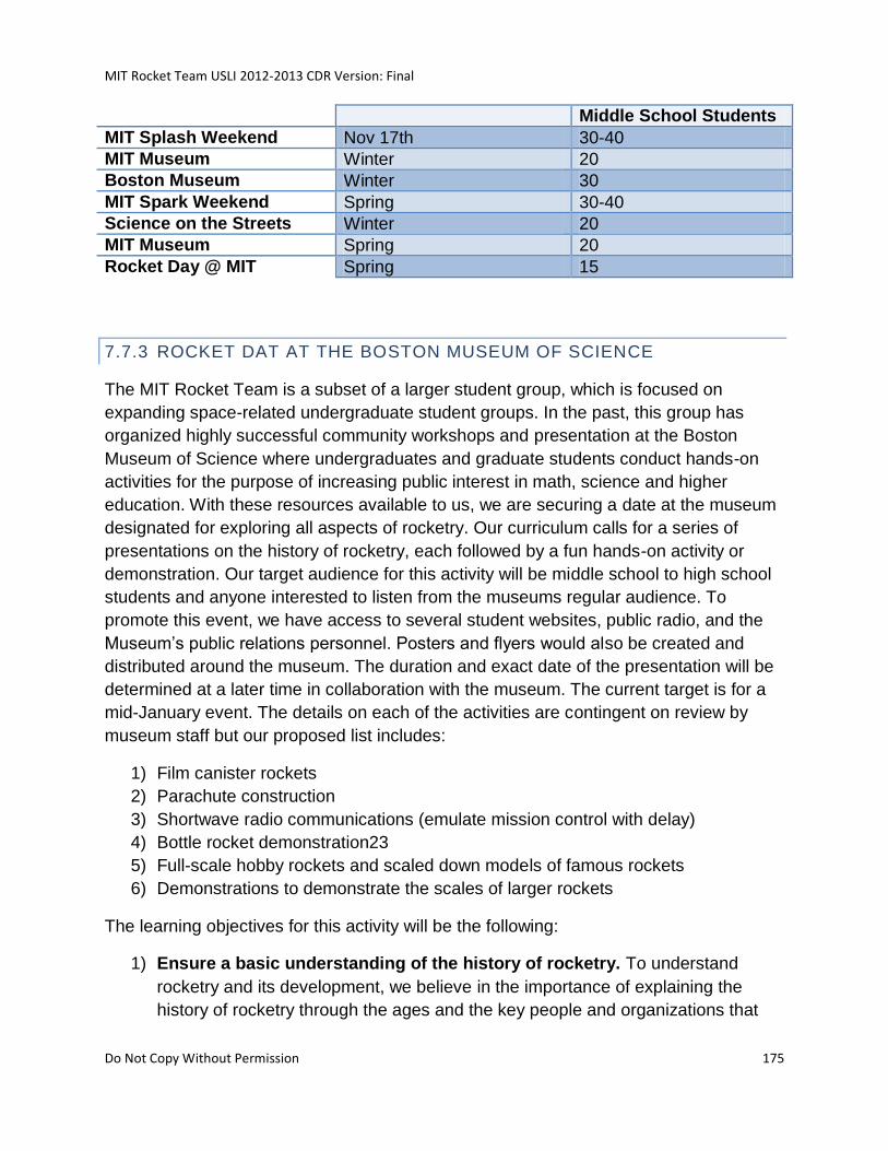
MIT Rocket Team USLI 2012-2013 CDR Version: Final
Do Not Copy Without Permission 175
Middle School Students
MIT Splash Weekend Nov 17th 30-40
MIT Museum Winter 20
Boston Museum Winter 30
MIT Spark Weekend Spring 30-40
Science on the Streets Winter 20
MIT Museum Spring 20
Rocket Day @ MIT Spring 15
7.7.3 ROCKET DAT AT THE BOSTON MUSEUM OF SCIENCE
The MIT Rocket Team is a subset of a larger student group, which is focused on
expanding space-related undergraduate student groups. In the past, this group has
organized highly successful community workshops and presentation at the Boston
Museum of Science where undergraduates and graduate students conduct hands-on
activities for the purpose of increasing public interest in math, science and higher
education. With these resources available to us, we are securing a date at the museum
designated for exploring all aspects of rocketry. Our curriculum calls for a series of
presentations on the history of rocketry, each followed by a fun hands-on activity or
demonstration. Our target audience for this activity will be middle school to high school
students and anyone interested to listen from the museums regular audience. To
promote this event, we have access to several student websites, public radio, and the
Museum’s public relations personnel. Posters and flyers would also be created and
distributed around the museum. The duration and exact date of the presentation will be
determined at a later time in collaboration with the museum. The current target is for a
mid-January event. The details on each of the activities are contingent on review by
museum staff but our proposed list includes:
1) Film canister rockets
2) Parachute construction
3) Shortwave radio communications (emulate mission control with delay)
4) Bottle rocket demonstration23
5) Full-scale hobby rockets and scaled down models of famous rockets
6) Demonstrations to demonstrate the scales of larger rockets
The learning objectives for this activity will be the following:
1) Ensure a basic understanding of the history of rocketry. To understand
rocketry and its development, we believe in the importance of explaining the
history of rocketry through the ages and the key people and organizations that
MIT Rocket Team USLI 2012-2013 CDR Version: Final
Do Not Copy Without Permission 176
have advanced this field. Topics will include Wernher von Braun, Robert
Goddard, NASA, the Space Race, and current commercial rockets such as
SpaceX’s Falcon 9.
2) How does a rocket work? The main premise for this activity is to explain how
rockets work and prime our target audience with an interest in math and science
through the amazing technology that are rockets. This portion of the presentation
will introduce the importance of math and science in developing rockets by
explaining the basics principles that allow us to send rockets into space. Hands-
on activities will be used to ensure a rich understanding of the basics of projectile
motion.
3) The social impact that low-Earth orbit rocketry has brought to our everyday
lives. This portion of our presentation will explore the invaluable contributions
that rockets have brought to our society from advancing our telecommunication
capability to allowing accurate weather forecasts to creating a paradigm shift into
our technology embedded world.
To evaluate the success of our engagement, we plan to include a session of questions
to the audience and rate their responses on accuracy with relationship to our
presentations and activities. Ideally, we would use entrance and exit surveys to
quantitatively measure the success of our public outreach in meeting our educational
goals. However due to the large range of ages expected, an interactive conversation is
more practical.
7.7.4 ROCKET DAY AT THE MIT MUSEUM
We plan to run a nearly identical event at the MIT Museum, which is an administrative
department of the Institute. The nature of the audience will allow us to be slightly more
technical in our presentation, and will expand the range of people we reach through our
efforts.
As with the Museum of Science, SEDS members have had successful experiences with
presenting at the MIT Museum in the past. We have gotten in touch with a member of
museum staff who has hosted us previously, and are currently working on securing a
date and duration for the event. The team has recently met with the staff of the MIT
museum and has begun to outline and schedule some potential activities.
7.7.5 MIT SPLASH AND SPARK WEEKENDS

MIT Rocket Team USLI 2012-2013 CDR Version: Final
Do Not Copy Without Permission 177
MIT’s Educational Studies Program is a student group that offers services to student
and community members alike. As part of its community outreach it offers student-
taught classes all weekend long during the months of November (called Splash) and
March (called Spark) on campus to a target group of 7th-12th graders. Registration to
teach a class is simple and we intend to offer several classes at these events. Our plan
is to use a presentation similar to that given at Splash. Splitting up the curriculum into
each of the three learning objectives and the activities related with each would be ideal.
We want them to understand that the field of engineering is not intimidating rather it
offers an exciting, fast-paced, and very innovative work environment. We aim to get the
students enthusiastic about pursuing math and science beyond high school. Since
these classes would be smaller and engaging, we plan to use entrance and exit surveys
to quantitatively gauge the learning that occurred. This will be useful to know if we need
any changes to the curriculum before presenting at the museum (which will occur after
Splash).
On November 17th 2012 the team taught a total 75 middle school and high school
students in the areas outlined in Figure 70 Splash List of Classes.
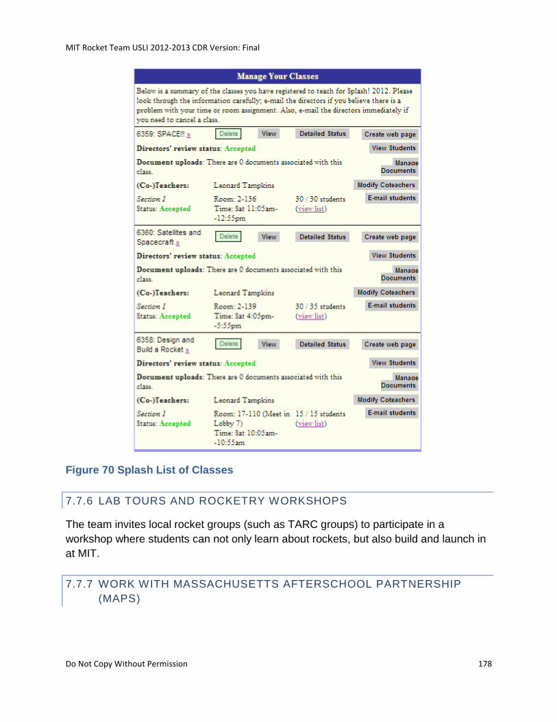
MIT Rocket Team USLI 2012-2013 CDR Version: Final
Do Not Copy Without Permission 178
Figure 70 Splash List of Classes
7.7.6 LAB TOURS AND ROCKETRY WORKSHOPS
The team invites local rocket groups (such as TARC groups) to participate in a
workshop where students can not only learn about rockets, but also build and launch in
at MIT.
7.7.7 WORK WITH MASSACHUSETTS AFTERSCHOOL PARTNERSHIP
(MAPS)
MIT Rocket Team USLI 2012-2013 CDR Version: Final
Do Not Copy Without Permission 179
The MAPS specializes in organizing afterschool programs for K to middle school
students. The executive members of the team have contacted MAPS in hopes of
creating a better outreach activity plan or other outreach ideas/activities.
7.7.8 SCIENCE ON THE STREET
As the USLI launch takes place during the Cambridge Science Festival the team will not
be able to participate in the Cambridge city wide rocket day. However, the same group
that runs this event told us that they were interested in having the MIT Rocket Team
participate in the monthly Science on the Street events.
8 CONCLUSION
For its entry into NASA’s University Student Launch Initiative, the MIT Rocket Team has
chosen to develop a simplified flight control interface to use in conjunction with a
Unmanned Aerial Vehicle to be deployed at 500 ft by a custom designed and fabricated
carbon fiber rocket. The team’s main goal in completing this challenge is to develop a
method that will allow for a significant reduction in the skill and training needed for the
successful operation of a rotorcraft. With this in mind the MIT Rocket Team anticipates
that in the near future rotorcraft flight systems similar to the one being developed will be
used on a greater scale than before for a wide variety of missions ranging from search
and rescue, to reconnaissance and even rapid scientific data acquisition.
With these applications in mind, the MIT Rocket Team has developed a rocket capable
of deploying a rotorcraft designed to fold up for storage inside of it. Furthermore, the
team has designed a flight mission that will simulate a tracking and reconnaissance
mission, while simultaneously completing the HALO experiment mission goals. During
the flight mission, the rotorcraft will be used to visually locate the drifting rocket, while
also gathering, transmitting, and storing all of the scientific data as mentioned in the
HALO requirements. By completing both of these tasks, the MIT Rocket Team will prove
the effectiveness of the flight system while performing the tasks for which it has been
developed. To facilitate this mission, software is being written to perform these tracking
methods autonomously. To make this a possible low cost, but robust system, off the
shelf autopilot system will take in GPS coordinates and IMU attitude data in real time
from the flight control system.
Once the preliminary design has been completed the team will move into the fabrication
and testing stage. With a goal of creating a strong and light launch vehicle, the MIT
Rocket Team has chosen a four-ply carbon fiber layup as the main material for a large
percentage of the rocket. The MIT Rocket Team has great skill working with composite
MIT Rocket Team USLI 2012-2013 CDR Version: Final
Do Not Copy Without Permission 180
materials, and for the past six years all rockets produced by the team have been
fabricated out of fiberglass and/or carbon fiber. The development of a rotorcraft however
is a new task for the MIT Rocket Team and the added complexities of designing an
aircraft that could fit within a 6 in body tube has been no easy task. However, the Team
has developed a simple and unique method to fold the arms of the rotorcraft allowing for
a sufficiently large craft to reliably perform all necessary tasks. In the following months
the MIT Rocket Team will transition from design work to testing and fabrication. With
this transition, the team is committed to completing all tasks necessary to stay on the
competition schedule. To help facilitate this task, the team has developed detailed
schedule, and planning meetings are held on a weekly basis to ensure that all tasks are
being completed on schedule.
9 APPENDIX
9.1 ROCKET MASTER EQUIPMENT LIST

MIT Rocket Team USLI 2012-2013 CDR Version: Final
Do Not Copy Without Permission 181
9.2 QUADROTOR BILL OF MATERIALS
Master Equipment List Updated on 10/28/12
ID # Subsystem Item name
Usage
Certainty Description (Vendor, part #, etc.) Cost/ Item
Mass
kg/Item # Items Location Total Cost ($)
Cost
Margin
Margined
Cost
Total Mass
(kg)
Mass
Measured
Mass
Margin
Margined
Mass
R01-01 Propulsion Motor Cessasroni L1115-P $247.00 2.394 1 247.00 247.00 2.394 0% 2.39
R01-02 Casing Pro75-4G $305.00 2.01 1 305.00 305.00 2.01 0% 2.01
R01-03 Igniter [comes with motor] $0.00 0 1 0.00 0.00 0 0% 0.00
Add rows above this row, do not delete this row
Total 552.00 20% 552.00 4.404 20% 4.40
Allocation 600.00 20% 720.00 4.45 20% 5.34
R02-01-01 Airframe-Body Stage Body: lower $91.00 0.90 1 91.00 91.00 0.9 0.90
R02-01-02 Stage Body: upper $109.00 1.02 1 109.00 109.00 1.02 1.02
R02-02 Bulkhead $10.00 0.09 1 10.00 10.00 0.0854 0.09
R02-03 Casing Spacing Ring $10.00 0.07 3 30.00 30.00 0.21 0.21
R02-04 Rail Guide railbuttons.com $1.25 0.05 2 2.50 2.50 0.1 0.10
R02-05 Adhesive $2.00 0.03 20 40.00 40.00 0.6 0.60
R02-06 Fin $8.00 0.24 4 32.00 32.00 0.96 0.96
R02-07-01 Coupler $9.00 0.21 1 9.00 9.00 0.21 0.21
R02-08 Avionics Tube $20.00 0.17 1 20.00 20.00 0.167 0.17
R02-09 Avionics Plate $10.00 0.32 1 10.00 10.00 0.32 0.32
R02-10 Eye Nut 3274T41 $6.59 0.15 1 6.59 6.59 0.15 0.15
R02-12 Payload Support Bulkhead $50.00 0.61 1 50.00 50.00 0.61 0.61
R02-13 Motor Mount Tube $15.00 0.08 1 15.00 15.00 0.08 0.08
R02-14 Motor Retention Plate $10.00 0.05 1 10.00 10.00 0.05 0.05
R02-15 Avionics Bolt Doubler $10.00 0.08 1 10.00 10.00 0.08 0.08
R02-16 Inserts 91732A355 $0.43 0.02 4 1.72 1.72 0.08 0.08
R02-19 Threaded Rod 98804A496 $3.63 0.16 1 3.63 3.63 0.16 0.16
R02-21 Access Door Nutplates 94579A100 $0.12 0.00 16 1.96 1.96 0.048 0.05
R02-22 Access Door Bolts 92196A148 $0.04 0.00 16 0.64 0.64 0.048 0.05Add rows above this row, do not delete this rowTotal 445.09 20% 445.09 5.88 20% 5.88Allocation 500.00 20% 600.00 5.90 20% 7.08
R03-01 Airframe-Fairing Fairing Body $94.45 0.68 1 94.45 94.45 0.68 0.68
Add rows above this row, do not delete this row
Total 94.45 20% 94.45 0.68 20% 0.68
Allocation 100.00 20% 120.00 0.7 20% 0.84
R04-01 Altimeter Perfect Flight StratoLogger $85.55 0.050 1 85.55 85.55 0.05 0.05
R04-02 Altimeter Feather Weight Raven $155.00 0.025 1 155.00 155.00 0.025 0.03
R04-03 Battery 9v Battery $2.67 0.050 2 5.33 5.33 0.1 0.10
R04-04 Tracking Transmitter bigredbee.com $85.00 0.010 2 170.00 170.00 0.02 0.02
R04-05 Kapton Tape $10.00 0.020 1 10.00 10.00 0.02 0.02
R04-06 Battery Holder Digikey BH9V-PC-ND $1.30 0.050 3 3.90 3.90 0.15 0.15
R04-07 Bolts 92196A148 $0.04 0.01 8 0.32 0.32 0.064 0.06
Add rows above this row, do not delete this row
Total 430.10 20% 430.10 0.429 20% 0.43
Allocation 1,000.00 20% 1,200.00 0.9 20% 1.08
R05-01 Payload Support Equipment Sabot Half $23.50 0.440 2 47.00 47.00 0.88 0.88
R05-02 Hard Point Half $20.00 0.240 4 80.00 80.00 0.96 0.96
R05-03 Stringer 94435A355 $6.45 0.050 4 25.80 25.80 0.2 0.20
R05-04 Eye-Bolt: Sabot Holder 3067T530 $5.44 0.075 3 16.32 16.32 0.225 0.23
R05-05 Tubular Nylon $10.00 0.050 1 10.00 10.00 0.05 0.05
R05-06 Sabot Hard Point Brace $5.00 0.040 4 20.00 20.00 0.16 0.16
Phenolic Tube $47.50 0.563 2 95.00 95.00 1.125 1.13
Add rows above this row, do not delete this row
Total 294.12 20% 294.12 3.6 20% 3.60
Allocation 300.00 20% 360.00 3.7 20% 4.44
R06-01 Recovery Main Chute Rocketman 14ft Standard $155.00 1.020 1 http://www.the-rocketman.com/chutes.html155.00 155.00 1.02 1.02
R06-02 Main Chute Deployment Bag TAC-9A $35.00 0.510 1 http://www.giantleaprocketry.com/products_recovery.asp35.00 35.00 0.51 0.51
R06-03 Drogue Chute Rocketman 4ft Ballistic Mach 1 $60.00 0.230 1 http://www.the-rocketman.com/chutes.html60.00 60.00 0.23 0.23
R06-04 Drogue Chute Protector Wildman 30"x30" chute protector $18.00 0.080 1 18.00 18.00 0.08 0.08
R06-05 Shock Cord McMaster #3510T11 $10.00 0.400 1 10.00 10.00 0.4 0.40
R06-06 Quicklink $5.00 0.010 4 20.00 20.00 0.04 0.04
R06-07 Charge+Wiring Wildman WMOI $1.69 0.010 4 6.78 6.78 0.04 0.04
R06-08 Shear Pin 97263A081 $0.05 0.002 4 0.20 0.20 0.008 0.01
R06-10 Black Powder
PowderInc: GMd5: PI20080927.16.06-
5 $2.00 0.005 1 2.00 2.00 0.005 0.01
R06-11 Charge Released Locking Mechanism
http://fruitychutes.com/Recovery_T
ether_Manual.pdf $85.00 0.020 1 85.00 85.00 0.02 0.02
R06-12 Shear Pin Insert 91732A203 $0.46 0.002 4 1.82 1.82 0.008 0.01
R06-13 Recovery Locknut 90631A011 $0.10 0.002 8 0.80 0.80 0.016 0.02
Add rows above this row, do not delete this row
Total 394.60 20% 394.60 2.377 20% 2.38
Allocation 400.00 20% 480.00 2.4 20% 2.88
Total 2,210.36 2,210.36 17.37 17.37
Allocation 2,900.00 3,480.00 18.05 21.66
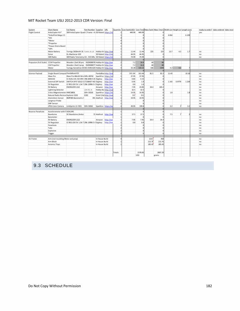
MIT Rocket Team USLI 2012-2013 CDR Version: Final
Do Not Copy Without Permission 182
9.3 SCHEDULE
System Short Name Full Name Part Number Supplier URL Quantity Cost Each(USD) Cost Total (USD)Mass Each(grams)Mass Total (grams)Width (cm)Height (cm)Length (cm) ready to order? date ordered date received
Flight Control ArduCopter Kit* 3DR ArduCopter Quad-C Frame + Motors + Full Flight Electronics Kit3D Roboticshttps://store.diydrones.com/3DR_ArduCopter_Quad_C_Full_flight_electronics_kit_p/kt-ac3dr-03.htm1 449.99 449.99 0 yes
*ArduPilot Mega 2.5 1 0 0 4.064 6.109
*ESC 4 0 0
*Motor 4 0 0
*Propeller 4 0 0
*Power Distro Board 1 0 0
*GPS 1 0 0
Motor Battery Turnigy 2650mAh 3S 20C Lipo PackT2650.3S.20 Hobby Kinghttp://www.hobbyking.com/hobbyking/store/uh_viewItem.asp?idProduct=92711 11.44 11.44 225 225 13.7 4.3 1.7 no
Sonar XL-MaxSonar-EZ0 3D Roboticshttp://store.diydrones.com/MB1200_XL_MaxSonar_EZ0_p/ac-0004-15.htm1 44.95 44.95 0 no
3DR Radio 3DR Radio Telemetry Kit - 915 Mhz 3D Roboticshttps://store.diydrones.com/3DR_RadioTelemetry_Kit_915_Mhz_p/kt-telemetry-3dr915.htm1 74.99 74.99 0 no
0 0
Propusion (Full Scale) CCW Propeller Wooden 13x4.5R propeller (1pc/bag)9329000078 Hobby Kinghttp://www.hobbyking.com/hobbyking/store/__24277__Wooden_13x4_5R_propeller_1pc_bag_.html2 7.2 14.4 40 80
CW Propeller Wooden 13x4.5 propeller (1pc/bag)9329000077 Hobby Kinghttp://www.hobbyking.com/hobbyking/store/__24276__Wooden_13x4_5_propeller_1pc_bag_.html2 7.2 14.4 40 80
Motor Turnigy Aerodrive SK3 - 4240-620kv Brushless Outrunner MotorSK3-4240-620 Hobby Kinghttp://www.hobbyking.com/hobbyking/store/__18167__Turnigy_Aerodrive_SK3_4240_620kv_Brushless_Outrunner_Motor.html4 33.28 133.12 336 1344 4.2 4.2 7
0 0
Science Payload Single Board ComputerPandaBoard ES PandaBoardhttp://pandaboard.org1 161.64 161.64 81.5 81.5 11.43 10.16 no
Xbee Pro Xbee Pro 60mW Wire Antenna - Series 1 (802.15.4)WRL-08742 SparkFun https://www.sparkfun.com/products/87421 37.95 37.95 0 no
MAX232 IC DUAL EIA-232 DRVR/RCVR 16-DIP296-6940-5-NDDigikey http://www.digikey.com/product-detail/en/MAX232IN/296-6940-5-ND/3715625 0.83 4.15 0 no
External DIP Switch SWITCH SPST GOLD SEALED 4 SECCT2064ST-ND Digikey http://www.digikey.com/product-detail/en/206-4ST/CT2064ST-ND/207742 0.95 1.9 0 1.143 0.9779 1.234 no
5V Regulator IC REG LDO 5V 1.5A TO-220-3296-13996-5-NDDigikey http://www.digikey.com/product-detail/en/UA7805CKCS/296-13996-5-ND/5216122 0.8 1.6 0 no
9V Battery ENERGIZER L522 Amazon http://www.amazon.com/Energizer-LA522-Industrial-Lithium-Detectors/dp/B0046TV5VO/ref=sr_1_3?ie=UTF8&qid=1350876001&sr=8-3&keywords=9v+battery+lithium3 7.95 23.85 34.4 103.2 no
Lightning Detector LD4-R1-A Hobby Boardshttp://www.hobby-boards.com/store/products/Lightning-Detector.html1 32.5 32.5 0 no
3 Axis Magnetometer HMC5883L SEN-10530 SparkFun https://www.sparkfun.com/products/105301 14.95 14.95 0 1.8 1.8 no
Natural Radio RecieverExplorer E202 E202 Sistel (Italy)http://www.comsistel.com/product.php?id_product=161 311 311 0 no
Atomshere Sensor BMP085 Barometric Pressure/Temperature/Altitude Sensor391 Adafruit http://www.adafruit.com/products/3911 19.95 19.95 0 no
Langmuir Probe 1 0 0 no
EMF Sensor 1 0 0 no
JPEG Color Camera LinkSprite LS-Y201 SEN-10061 Sparkfun https://www.sparkfun.com/products/100614 49.95 199.8 0 3.2 3 3.2 no
0 0
Reserve Parachute Accelerometer with Free Fall DetectionADXL345 1 0 0
Boarduino DC Boarduino (Arduino compatible) Kit (w/ATmega328) - v1.072 Adafruit http://www.adafruit.com/products/721 17.5 17.5 0 7.5 1 2 no
Barometer 1 0 0 no
9V Battery ENERGIZER L522 Amazon http://www.amazon.com/Energizer-LA522-Industrial-Lithium-Detectors/dp/B0046TV5VO/ref=sr_1_3?ie=UTF8&qid=1350876001&sr=8-3&keywords=9v+battery+lithium1 7.95 7.95 34.4 34.4 no
5V Regulator IC REG LDO 5V 1.5A TO-220-3296-13996-5-NDDigikey http://www.digikey.com/product-detail/en/UA7805CKCS/296-13996-5-ND/5216121 0.8 0.8 0 no
Parachute 2 0 0 no
Tube 2 0 0 no
Explosive 2 0 0 no
Trigger 2 0 0 no
Air Frame Arm (not inculding Motor and prop) In House Build 4 114.5 458 no
Arm Block In House Build 1 215.76 215.76 no
Avionics Trays In House Build 1 185.43 185.43 no
Totals: 1578.83 2807.29
USD grams
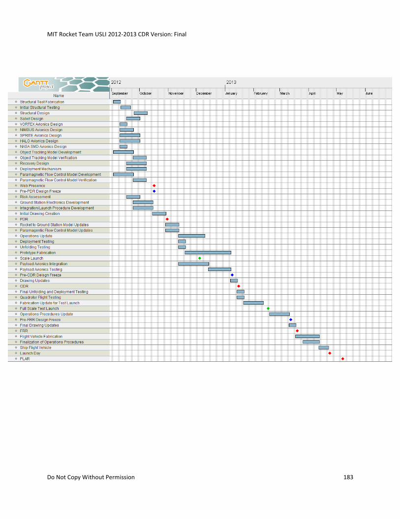
MIT Rocket Team USLI 2012-2013 CDR Version: Final
Do Not Copy Without Permission 183
MIT Rocket Team USLI 2012-2013 CDR Version: Final
Do Not Copy Without Permission 184
9.4 CAD MODELS
9.5 MECHANICAL DRAWINGS
9.6 CIRCUIT SCHEMATICS
9.7 PCB DESIGNS
9.8 MANUFACTURING PLAN
9.9 CODE OVERVIEW
9.10 NIMBUS
NIMBUS
Mission Motivation
One Atmosphere Uniform Glow Discharge Plasma (OAUGDP) experiments have soon
that it can accelerate flow and reattach boundary layers at velocities of several
hundreds of meters per second. OAUGDP has not been applied to rockets for use as an
active stabilization controller. Also, field testing of OAUGDP is very minimal. A control
system and boundary layer measurement device will be built to test the possibility of
using OAUGDP as a possible stabilization method and to acquire more field data on
how OAUGDP systems perform in a dynamic environment over a range of pressures
and neutral flow velocities.
In summary the team aims to:
Study the effects of an Electrohydrodynamic (EHD) accelerated flow system on
rocket flight stability
MISSION STATEMENT
The MIT Rocket Team aims to develop an inexpensive, customizable, and reusable
rocket system with an EHD accelerated flow measurement and control system.
MISSION REQUIRMENTS
The NIMBUS payload will meet the following objectives:
o Easy integration
o Reusable
MIT Rocket Team USLI 2012-2013 CDR Version: Final
Do Not Copy Without Permission 185
o Powered from a low voltage source
o Safe: non-lethal currents
o Measure ability to control rocket attitude within the velocity range of ____
meters per second
PAYLOAD DETAILS
The stabilization system is a system integrated in the rockets fiberglass nose cone that
uses electrodes to accelerate the air around the nose cone. This effect reattaches the
flow around the fins thereby reducing turbulent flow and improving the rocket’s drag
profile. Individually controlling the acceleration of the flow on each side of the fins
should alter the drag profile of the fins causing the rocket to slightly change its
orientation. The switching circuit for this system will be controlled by a gyroscope/tilt
sensor with a fast sample rate and a fast microprocessor such as the STM32. This
circuitry and power supply will be housed in the rocket avionics bay.
Figure 71 NIMBUS overview diagram
THEORY
“The development of the One Atmosphere Uniform Glow Discharge Plasma (OAUGDP)
in a flat surface layer has made it possible to exert significant EHD body forces in the
boundary layer above electrodes on aerodynamic surfaces.” (Roth, 2001)The neutral
air is accelerated due to the EHD body force induced by peristaltic flow acceleration.
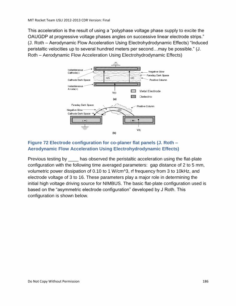
MIT Rocket Team USLI 2012-2013 CDR Version: Final
Do Not Copy Without Permission 186
This acceleration is the result of using a “polyphase voltage phase supply to excite the
OAUGDP at progressive voltage phases angles on successive linear electrode strips.”
(J. Roth – Aerodynamic Flow Acceleration Using Electrohydrodynamic Effects) “Induced
peristaltic velocities up to several hundred meters per second…may be possible.” (J.
Roth – Aerodynamic Flow Acceleration Using Electrohydrodynamic Effects)
Figure 72 Electrode configuration for co-planer flat panels (J. Roth –
Aerodynamic Flow Acceleration Using Electrohydrodynamic Effects)
Previous testing by ____ has observed the peristaltic acceleration using the flat-plate
configuration with the following time averaged parameters: gap distance of 2 to 5 mm,
volumetric power dissipation of 0.10 to 1 W/cm^3, rf frequency from 3 to 10kHz, and
electrode voltage of 3 to 16. These parameters play a major role in determining the
initial high voltage driving source for NIMBUS. The basic flat-plate configuration used is
based on the “asymmetric electrode configuration” developed by J Roth. This
configuration is shown below.
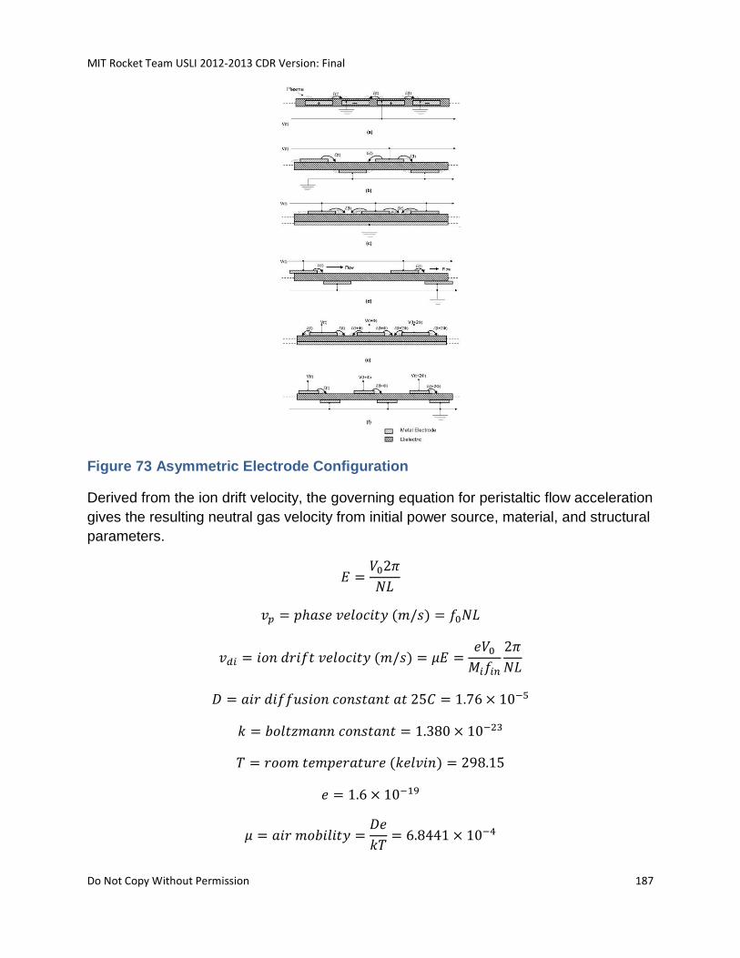
MIT Rocket Team USLI 2012-2013 CDR Version: Final
Do Not Copy Without Permission 187
Figure 73 Asymmetric Electrode Configuration
Derived from the ion drift velocity, the governing equation for peristaltic flow acceleration
gives the resulting neutral gas velocity from initial power source, material, and structural
parameters.
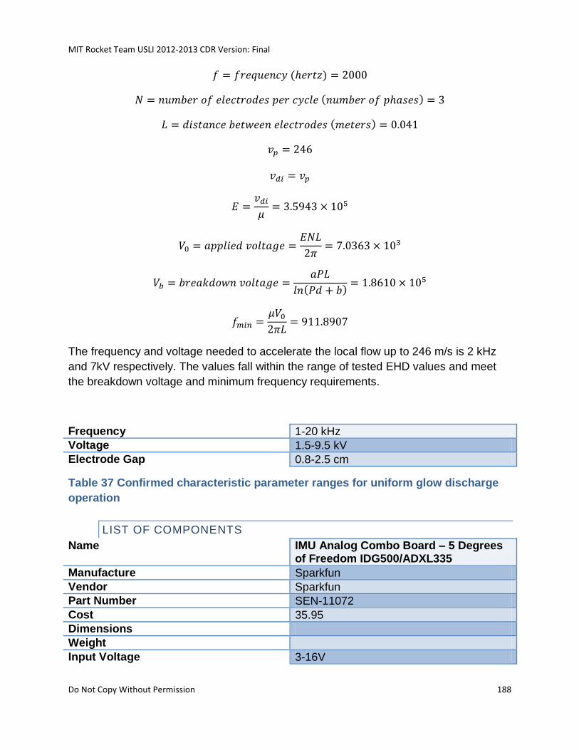
MIT Rocket Team USLI 2012-2013 CDR Version: Final
Do Not Copy Without Permission 188
The frequency and voltage needed to accelerate the local flow up to 246 m/s is 2 kHz
and 7kV respectively. The values fall within the range of tested EHD values and meet
the breakdown voltage and minimum frequency requirements.
Frequency 1-20 kHz
Voltage 1.5-9.5 kV
Electrode Gap 0.8-2.5 cm
Table 37 Confirmed characteristic parameter ranges for uniform glow discharge
operation
LIST OF COMPONENTS
Name IMU Analog Combo Board – 5 Degrees of Freedom IDG500/ADXL335
Manufacture Sparkfun
Vendor Sparkfun
Part Number SEN-11072
Cost 35.95
Dimensions
Weight
Input Voltage 3-16V
MIT Rocket Team USLI 2012-2013 CDR Version: Final
Do Not Copy Without Permission 189
Gyro Range 500 degrees/second
Accelerometer Range +/- 3g
Signals Out Analog
Description
The IMU measures the attitude of the rocket.
Name Atomik Ignition Coil for Venom 26cc Gas Engine
Manufacture Atomik
Vendor Atomik
Cost 14.99
Dimensions
Weight
Description
Raises the voltage level of outputted by the transformer.
Name High Voltage Power Supply Kit
Manufacture Images Scientific Instruments
Vendor Images Scientific Instruments
Part Number HVPS-01
Cost 84.95
Dimensions
Weight
Input Voltage 24V
Output Voltage 7-17 kV
Output Frequency 1000-2000 Hz
Maximum Current 300 mA
Description
Outputs a high voltage and high frequency signal from an low voltage DC input.
Name LM555
Manufacture Fairchild
Vendor Digikey
Part Number LM555CNFS-ND
Cost 0.43
Dimensions
Weight
Input Voltage 4.5-16V
Maximum Current 200 mA
Footprint 8-DIP
MIT Rocket Team USLI 2012-2013 CDR Version: Final
Do Not Copy Without Permission 190
Description
Timer
Name LM2904P
Manufacture Texas Instruments
Vendor Digikey
Part Number 296-9528-5-ND
Cost 0.49
Dimensions
Weight
Input Voltage 2-14V
Output Voltage 2-14V
Output Frequency 20 kHz
Maximum Current 800 mA
Footprint 8-SOP
Description
3-phase brushless DC sinusoidal sensor-less fan motor driver
Name HV Transistor TBD
Manufacture Fairchild
Vendor Digikey
Part Number LM555CNFS-ND
Cost 0.43
Dimensions
Weight
Input Voltage 4.5-16V
Maximum Current 200 mA
Footprint 8-DIP
Description
Drivers the frequency of the transformer
Name STM32F4DISCOVERY
Manufacture STMicroelectronics
Vendor Digikey
Part Number 497-11455-ND
Cost 14.90
Dimensions
MIT Rocket Team USLI 2012-2013 CDR Version: Final
Do Not Copy Without Permission 191
Weight
Input Voltage 3V or 5V
Gyro Range 500 degrees/second
Accelerometer Range +/- 3g
Signals Analog, SPI, UART, I2C, PWM
Description
Main CPU
Batteries 3.3V x 1; 24V x 1
Output Voltage Range 3.3V-7kV
Current Maximum 300mA
OPERATIONS DURING ROCKET ASCENT
During ascent the EHD flow acceleration system will turn on various rows of electrodes
on various sides of the fins depending on the attitude of the rocket. The EHD flow
measurement system will try to measure any induced changes in the flow velocities or
local boundary layers.
BUDGET
NIMBUS Structure 30
Avionics 250
Power 30
MIT Rocket Team USLI 2012-2013 CDR Version: Final
Do Not Copy Without Permission 192
9.11 DESCOPE PLAN
As the nature of this project is very complex in order to ensure that the team does not
run over schedule, over budget, or that deliverables are not subpar sections of the
project will be descoped in order of their importance. Sections will be descoped once
the team determines that their milestones cannot be met without sacrificing resources
from more important sections.
The order at which sections will be descoped is as follows:
1. NIMBUS
2. Object tracking
3. HALO
9.12 OBSERVED REGULATIONS AND SAFETY REQUIREMENTS
9.13 SIGNED DOCUMENTS
9.13.1 SAFETY AGREEMENTS
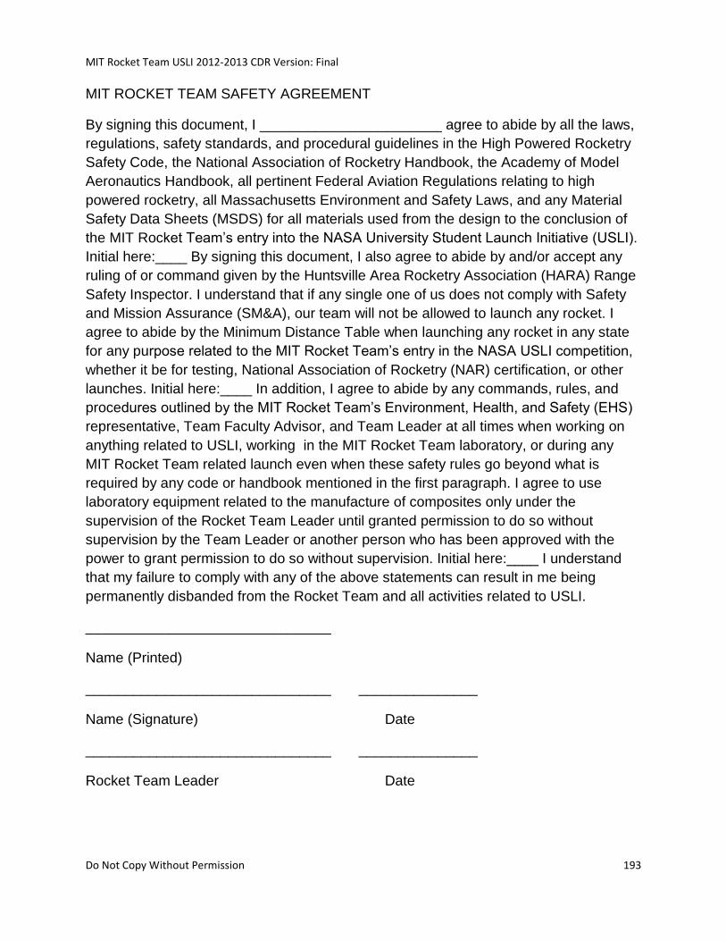
MIT Rocket Team USLI 2012-2013 CDR Version: Final
Do Not Copy Without Permission 193
MIT ROCKET TEAM SAFETY AGREEMENT
By signing this document, I _______________________ agree to abide by all the laws,
regulations, safety standards, and procedural guidelines in the High Powered Rocketry
Safety Code, the National Association of Rocketry Handbook, the Academy of Model
Aeronautics Handbook, all pertinent Federal Aviation Regulations relating to high
powered rocketry, all Massachusetts Environment and Safety Laws, and any Material
Safety Data Sheets (MSDS) for all materials used from the design to the conclusion of
the MIT Rocket Team’s entry into the NASA University Student Launch Initiative (USLI).
Initial here:____ By signing this document, I also agree to abide by and/or accept any
ruling of or command given by the Huntsville Area Rocketry Association (HARA) Range
Safety Inspector. I understand that if any single one of us does not comply with Safety
and Mission Assurance (SM&A), our team will not be allowed to launch any rocket. I
agree to abide by the Minimum Distance Table when launching any rocket in any state
for any purpose related to the MIT Rocket Team’s entry in the NASA USLI competition,
whether it be for testing, National Association of Rocketry (NAR) certification, or other
launches. Initial here:____ In addition, I agree to abide by any commands, rules, and
procedures outlined by the MIT Rocket Team’s Environment, Health, and Safety (EHS)
representative, Team Faculty Advisor, and Team Leader at all times when working on
anything related to USLI, working in the MIT Rocket Team laboratory, or during any
MIT Rocket Team related launch even when these safety rules go beyond what is
required by any code or handbook mentioned in the first paragraph. I agree to use
laboratory equipment related to the manufacture of composites only under the
supervision of the Rocket Team Leader until granted permission to do so without
supervision by the Team Leader or another person who has been approved with the
power to grant permission to do so without supervision. Initial here:____ I understand
that my failure to comply with any of the above statements can result in me being
permanently disbanded from the Rocket Team and all activities related to USLI.
_______________________________
Name (Printed)
_______________________________ _______________
Name (Signature) Date
_______________________________ _______________
Rocket Team Leader Date

MIT Rocket Team USLI 2012-2013 CDR Version: Final
Do Not Copy Without Permission 194
9.13.2 EDUCATIONAL ENGAGEMENT FORM
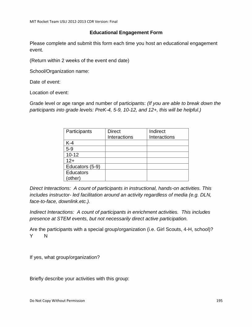
MIT Rocket Team USLI 2012-2013 CDR Version: Final
Do Not Copy Without Permission 195
Educational Engagement Form
Please complete and submit this form each time you host an educational engagement
event.
(Return within 2 weeks of the event end date)
School/Organization name:
Date of event:
Location of event:
Grade level or age range and number of participants: (If you are able to break down the
participants into grade levels: PreK-4, 5-9, 10-12, and 12+, this will be helpful.)
Participants Direct Interactions
Indirect Interactions
K-4
5-9
10-12
12+
Educators (5-9)
Educators (other)
Direct Interactions: A count of participants in instructional, hands-on activities. This
includes instructor- led facilitation around an activity regardless of media (e.g. DLN,
face-to-face, downlink.etc.).
Indirect Interactions: A count of participants in enrichment activities. This includes
presence at STEM events, but not necessarily direct active participation.
Are the participants with a special group/organization (i.e. Girl Scouts, 4-H, school)?
Y N
If yes, what group/organization?
Briefly describe your activities with this group:
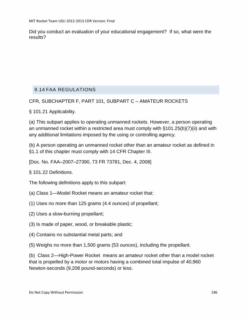
MIT Rocket Team USLI 2012-2013 CDR Version: Final
Do Not Copy Without Permission 196
Did you conduct an evaluation of your educational engagement? If so, what were the results?
9.14 FAA REGULATIONS
CFR, SUBCHAPTER F, PART 101, SUBPART C – AMATEUR ROCKETS
§ 101.21 Applicability.
(a) This subpart applies to operating unmanned rockets. However, a person operating
an unmanned rocket within a restricted area must comply with §101.25(b)(7)(ii) and with
any additional limitations imposed by the using or controlling agency.
(b) A person operating an unmanned rocket other than an amateur rocket as defined in
§1.1 of this chapter must comply with 14 CFR Chapter III.
[Doc. No. FAA–2007–27390, 73 FR 73781, Dec. 4, 2008]
§ 101.22 Definitions.
The following definitions apply to this subpart:
(a) Class 1—Model Rocket means an amateur rocket that:
(1) Uses no more than 125 grams (4.4 ounces) of propellant;
(2) Uses a slow-burning propellant;
(3) Is made of paper, wood, or breakable plastic;
(4) Contains no substantial metal parts; and
(5) Weighs no more than 1,500 grams (53 ounces), including the propellant.
(b) Class 2—High-Power Rocket means an amateur rocket other than a model rocket
that is propelled by a motor or motors having a combined total impulse of 40,960
Newton-seconds (9,208 pound-seconds) or less.

MIT Rocket Team USLI 2012-2013 CDR Version: Final
Do Not Copy Without Permission 197
(c) Class 3—Advanced High-Power Rocket means an amateur rocket other than a
model rocket or high-power rocket. [Doc. No. FAA–2007–27390, 73
FR 73781, Dec. 4, 2008]
§ 101.23General operating limitations.
(a) You must operate an amateur rocket in such a manner that it:
(1) Is launched on a suborbital trajectory;
(2) When launched, must not cross into the territory of a foreign country unless an
agreement is in place between the United States and the country of concern;
(3) Is unmanned; and
(4) Does not create a hazard to persons, property, or other aircraft.
(b) The FAA may specify additional operating limitations necessary to ensure that air
traffic is not adversely affected, and public safety is not jeopardized. [Doc. No. FAA–
2007–27390, 73 FR 73781, Dec. 4, 2008]
§ 101.25 Operating limitations for Class 2-High Power Rockets and
Class 3- Advanced High Power Rockets.
When operating Class 2-High Power Rockets or Class 3-Advanced High
Power Rockets, you must comply with the General Operating Limitations of
§101.23. In addition, you must not operate Class 2-High Power Rockets or
Class 3-Advanced High Power Rockets—
(a) At any altitude where clouds or obscuring phenomena of more than fivetenths
coverage prevails;
(b) At any altitude where the horizontal visibility is less than five miles;
(c) Into any cloud;
(d) Between sunset and sunrise without prior authorization from the FAA;
(e) Within 9.26 kilometers (5 nautical miles) of any airport boundary without prior
authorization from the FAA;
(f) In controlled airspace without prior authorization from the FAA;
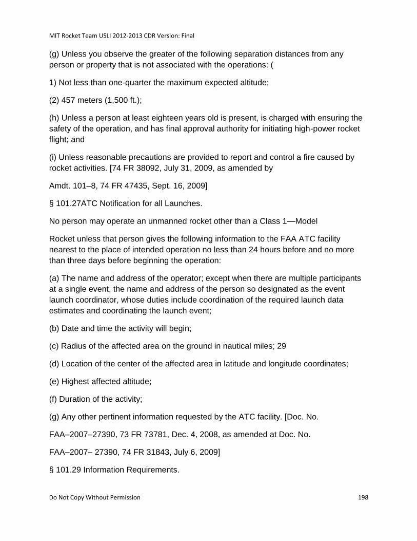
MIT Rocket Team USLI 2012-2013 CDR Version: Final
Do Not Copy Without Permission 198
(g) Unless you observe the greater of the following separation distances from any
person or property that is not associated with the operations: (
1) Not less than one-quarter the maximum expected altitude;
(2) 457 meters (1,500 ft.);
(h) Unless a person at least eighteen years old is present, is charged with ensuring the
safety of the operation, and has final approval authority for initiating high-power rocket
flight; and
(i) Unless reasonable precautions are provided to report and control a fire caused by
rocket activities. [74 FR 38092, July 31, 2009, as amended by
Amdt. 101–8, 74 FR 47435, Sept. 16, 2009]
§ 101.27ATC Notification for all Launches.
No person may operate an unmanned rocket other than a Class 1—Model
Rocket unless that person gives the following information to the FAA ATC facility
nearest to the place of intended operation no less than 24 hours before and no more
than three days before beginning the operation:
(a) The name and address of the operator; except when there are multiple participants
at a single event, the name and address of the person so designated as the event
launch coordinator, whose duties include coordination of the required launch data
estimates and coordinating the launch event;
(b) Date and time the activity will begin;
(c) Radius of the affected area on the ground in nautical miles; 29
(d) Location of the center of the affected area in latitude and longitude coordinates;
(e) Highest affected altitude;
(f) Duration of the activity;
(g) Any other pertinent information requested by the ATC facility. [Doc. No.
FAA–2007–27390, 73 FR 73781, Dec. 4, 2008, as amended at Doc. No.
FAA–2007– 27390, 74 FR 31843, July 6, 2009]
§ 101.29 Information Requirements.
MIT Rocket Team USLI 2012-2013 CDR Version: Final
Do Not Copy Without Permission 199
(a) Class 2—High-Power Rockets. When a Class 2—High-Power Rocket requires a
certificate of waiver or authorization, the person planning the operation must provide the
information below on each type of rocket to the FAA at least 45 days before the
proposed operation. The FAA may request additional information if necessary to ensure
the proposed operations can be safely conducted. The information shall include for
each type of Class 2 rocket expected to be flown:
(1) Estimated number of rockets,
(2) Type of propulsion (liquid or solid), fuel(s) and oxidizer(s),
(3) Description of the launcher(s) planned to be used, including any airborne
platform(s),
(4) Description of recovery system,
(5) Highest altitude, above ground level, expected to be reached,
(6) Launch site latitude, longitude, and elevation, and
(7) Any additional safety procedures that will be followed.
(b) Class 3—Advanced High-Power Rockets. When a Class 3—Advanced
High-Power Rocket requires a certificate of waiver or authorization the person planning
the operation must provide the information below for each type of rocket to the FAA at
least 45 days before the proposed operation.
The FAA may request additional information if necessary to ensure the proposed
operations can be safely conducted. The information shall include for each type of Class
3 rocket expected to be flown:
(1) The information requirements of paragraph (a) of this section,
(2) Maximum possible range,
(3) The dynamic stability characteristics for the entire flight profile,
(4) A description of all major rocket systems, including structural, pneumatic, propellant,
propulsion, ignition, electrical, avionics, recovery, wind-weighting, flight control, and
tracking,
(5) A description of other support equipment necessary for a safe operation,
(6) The planned flight profile and sequence of events, 30
MIT Rocket Team USLI 2012-2013 CDR Version: Final
Do Not Copy Without Permission 200
(7) All nominal impact areas, including those for any spent motors and other discarded
hardware, within three standard deviations of the mean impact point,
(8) Launch commit criteria,
(9) Countdown procedures, and
(10) Mishap procedures.
[Doc. No. FAA–2007–27390, 73 FR 73781, Dec. 4, 2008, as amended at
Doc. No. FAA–2007– 27390, 74 FR 31843, July 6, 2009]
9.15 HIGH POWER ROCKET SAFETY CODE
NFPA 1127 “Code for High Power Rocket Motors”
[http://www.nar.org/NARhpsc.html]
1. Certification. I will only fly high power rockets or possess high power rocket motors
that are within the scope of my user certification and required licensing.
2. Materials. I will use only lightweight materials such as paper, wood, rubber, plastic,
fiberglass, or when necessary ductile metal, for the construction of my rocket.
3. Motors. I will use only certified, commercially made rocket motors, and will not
tamper with these motors or use them for any purposes except those recommended by
the manufacturer. I will not allow smoking, open flames, nor heat sources within 25 feet
of these motors.
4. Ignition System. I will launch my rockets with an electrical launch system, and with
electrical motor igniters that are installed in the motor only after my rocket is at the
launch pad or in a designated prepping area. My launch system will have a safety
interlock that is in series with the launch switch that is not installed until my rocket is
ready for launch, and will use a launch switch that returns to the "off" position when
released. If my rocket has onboard ignition systems for motors or recovery devices,
these will have safety interlocks that interrupt the current path until the rocket is at the
launch pad.
5. Misfires. If my rocket does not launch when I press the button of my electrical launch
system, I will remove the launcher's safety interlock or disconnect its battery, and will
wait 60 seconds after the last launch attempt before allowing anyone to approach the
rocket.
MIT Rocket Team USLI 2012-2013 CDR Version: Final
Do Not Copy Without Permission 201
6. Launch Safety. I will use a 5-second countdown before launch. I will 31ensure that
no person is closer to the launch pad than allowed by the accompanying Minimum
Distance Table, and that a means is available to warn participants and spectators in the
event of a problem. I will check the stability of my rocket before flight and will not fly it if
it cannot be determined to be stable.
7. Launcher. I will launch my rocket from a stable device that provides rigid guidance
until the rocket has attained a speed that ensures a stable flight, and that is pointed to
within 20 degrees of vertical. If the wind speed exceeds 5 miles per hour I will use a
launcher length that permits the rocket to attain a safe velocity before separation from
the launcher. I will use a blast deflector to prevent the motor's exhaust from hitting
accordance with the accompanying Minimum Distance table, and will increase this
distance by a factor of 1.5 if the rocket motor being launched uses titanium sponge in
the propellant.
8. Size. My rocket will not contain any combination of motors that total more than
40,960 N-sec (9208 pound-seconds) of total impulse. My rocket will not weigh more at
liftoff than one-third of the certified average thrust of the high power rocket motor(s)
intended to be ignited at launch.
9. Flight Safety. I will not launch my rocket at targets, into clouds, near airplanes, nor
on trajectories that take it directly over the heads of spectators or beyond the
boundaries of the launch site, and will not put any flammable or explosive payload in my
rocket. I will not launch my rockets if wind speeds exceed 20 miles per hour. I will
comply with Federal Aviation Administration airspace regulations when flying, and will
ensure that my rocket will not exceed any applicable altitude limit in effect at that launch
site.
10. Launch Site. I will launch my rocket outdoors, in an open area where trees, power
lines, buildings, and persons not involved in the launch do not present a hazard, and
that is at least as large on its smallest dimension as one-half of the maximum altitude to
which rockets are allowed to be flown at that site or 1500 feet, whichever is greater.
11. Launcher Location. My launcher will be 1500 feet from any inhabited building or
from any public highway on which traffic flow exceeds 10 vehicles per hour, not
including traffic flow related to the launch. It will also be no closer than the appropriate
Minimum Personnel Distance from the accompanying table from any boundary of the
launch site.
12. Recovery System. I will use a recovery system such as a parachute in my rocket
so that all parts of my rocket return safely and undamaged and can be flown again, and
I will use only flame-resistant or fireproof recovery 32system wadding in my rocket.

MIT Rocket Team USLI 2012-2013 CDR Version: Final
Do Not Copy Without Permission 202
13. Recovery Safety. I will not attempt to recover my rocket from power lines, tall trees,
or other dangerous places, fly it under conditions where it is likely to recover in
spectator areas or outside the launch site, nor attempt to catch it as it approaches the
ground.
MIT Rocket Team USLI 2012-2013 CDR Version: Final
Do Not Copy Without Permission 203
10 MISC SAMPLE DOCUMENTS
10.1 ADVERTISEMENTS
10.1.1 OFFICIAL 2012 DEPARTMENTAL POSTER
10.1.2 MULTIMEDIA DISPLAY
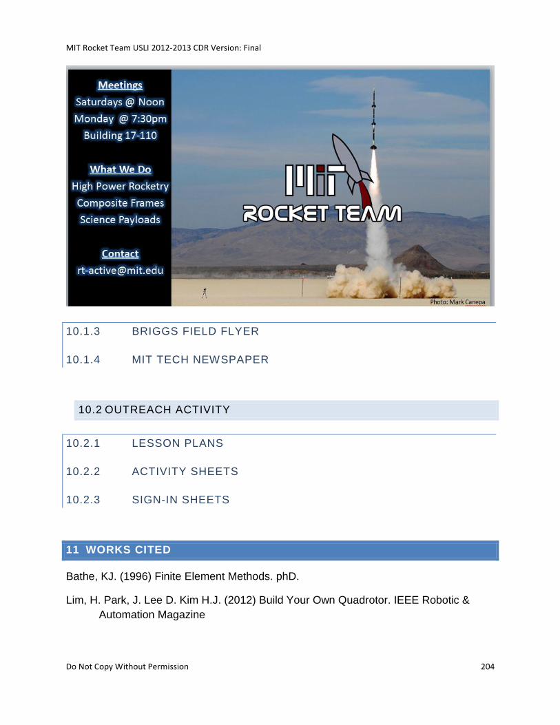
MIT Rocket Team USLI 2012-2013 CDR Version: Final
Do Not Copy Without Permission 204
10.1.3 BRIGGS FIELD FLYER
10.1.4 MIT TECH NEWSPAPER
10.2 OUTREACH ACTIVITY
10.2.1 LESSON PLANS
10.2.2 ACTIVITY SHEETS
10.2.3 SIGN-IN SHEETS
11 WORKS CITED
Bathe, KJ. (1996) Finite Element Methods. phD.
Lim, H. Park, J. Lee D. Kim H.J. (2012) Build Your Own Quadrotor. IEEE Robotic &
Automation Magazine

MIT Rocket Team USLI 2012-2013 CDR Version: Final
Do Not Copy Without Permission 205
Krehbiel, J., Brace, L., Theis, R., Cutler, J., Pinkus, W., & Kaplan, R. (1980). Pioneer
Venus Orbiter Electron Temperature Probe. IEEE Transactions on Geoscience
and Remote Sensing, Volume GE 18, Number 1, 49-54.
Roth, J. (2001). Aerodynamic Flow Acceleration Using Electrohydrodynamic Effects.
IEEE.
Warner, N. (2001). Performance Testing and Internal Probe Measurements.
Massachusetts Institute of Technology.