Embed Size (px)
Citation preview
processes
Article
Mitigation of Chromium Poisoning of FerriticInterconnect from Annealed Spinel of CuFe2O4
Muhammad Aqib Hassan * and Othman Bin Mamat
Department of Mechanical Engineering, Universiti Teknologi PETRONAS, 32610 Seri Iskandar,Perak Darul Ridzuan, Malaysia; [email protected]* Correspondence: [email protected]; Tel.: +60-10-257-5308
Received: 31 July 2020; Accepted: 19 August 2020; Published: 8 September 2020
Abstract: Low-temperature solid oxide fuel cells permit the possibility of metallic interconnects overconventional ceramic interconnects. Among various metallic interconnects, the ferritic interconnectsare the most promising. However, chromium poisoning in them adversely affects their performance.To resolve this issue, various coatings and pretreatment methods have been studied. Herein, this articleencloses the coating of CuFe2O4 spinel over two prominent ferritic interconnects (Crofer 22 APU andSUS 430). The CuFe2O4 spinel layer coating has been developed by the dip-coating of both samplesin CuFe2O4 slurry, followed by heat treatment at 800 C in a reducing environment (5% hydrogenand 95% nitrogen). Additionally, both samples were annealed to further enhance their spinel coatingstructure. The morphological and crystallinity analysis confirmed that the spinel coating formedmultiple layers of protection while annealing further reduced the thickness and improved the densities.Moreover, the area-specific resistance (ASR) and weight gain rate (WGR) of both samples before andafter annealing was calculated using mathematical modeling, which matches with the experimentaldata. It has been noted that CuFe2O4 spinel coating improved the ASR and WGR of both sampleswhich were further improved after annealing. This research reveals that the CuFe2O4 spinel is thepromising protective layer for ferritic interconnects and annealing is the better processing techniquefor achieving the preferred properties.
Keywords: Solid Oxide Fuel Cell; copper-ferrous oxide; coating; metallic interconnect; SUS 430;Crofer 22 APU
1. Introduction
Limited reserves of fossil fuels and increasing demand for clean energy have increased the needfor alternative sources of power. Among different power generation systems, the fuel cell is the mostpromising technology [1,2] that generates electricity from chemical reactions in an eco-friendly way.
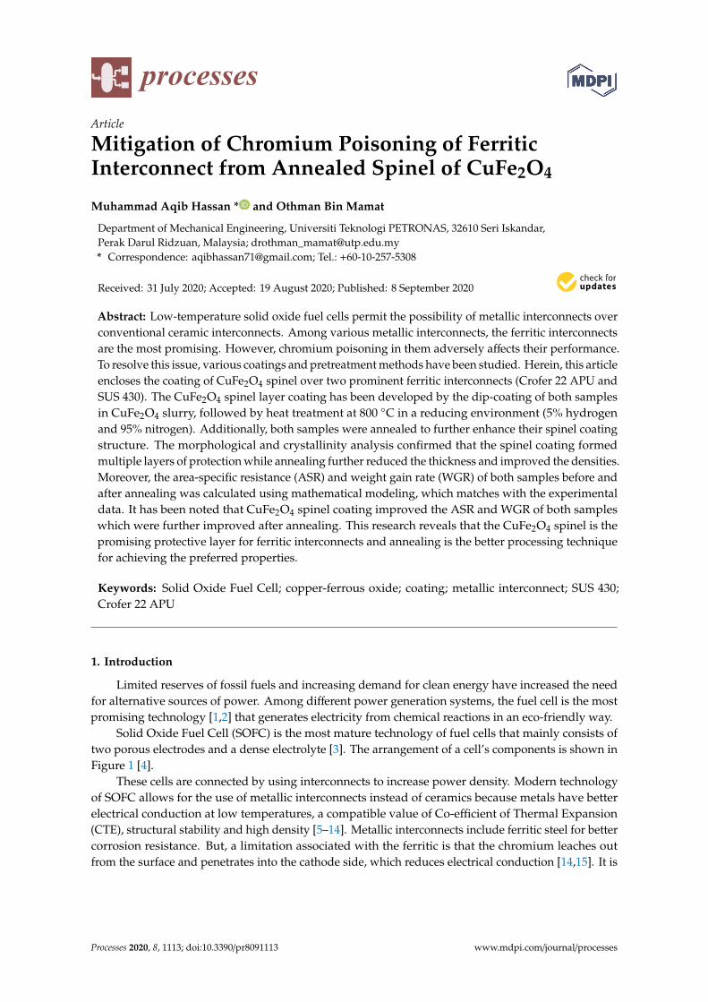
Solid Oxide Fuel Cell (SOFC) is the most mature technology of fuel cells that mainly consists oftwo porous electrodes and a dense electrolyte [3]. The arrangement of a cell’s components is shown inFigure 1 [4].
These cells are connected by using interconnects to increase power density. Modern technologyof SOFC allows for the use of metallic interconnects instead of ceramics because metals have betterelectrical conduction at low temperatures, a compatible value of Co-efficient of Thermal Expansion(CTE), structural stability and high density [5–14]. Metallic interconnects include ferritic steel for bettercorrosion resistance. But, a limitation associated with the ferritic is that the chromium leaches outfrom the surface and penetrates into the cathode side, which reduces electrical conduction [14,15]. It is
Processes 2020, 8, 1113; doi:10.3390/pr8091113 www.mdpi.com/journal/processes
Processes 2020, 8, 1113 2 of 14
noticed that the chrome layer (Cr2O3) oxidizes during operation and produces a volatile specie ofchrome, i.e., CrO2(OH)2, as per the following reaction:
2Cr2O3 + 4H2O + 3O2→ 4CrO2(OH)2
Processes 2020, 8, x; doi: FOR PEER REVIEW www.mdpi.com/journal/processes
Article
Mitigation of Chromium Poisoning of Ferritic Interconnect from Annealed Spinel of CuFe2O4
Muhammad Aqib Hassan *, Othman Bin Mamat
Department of Mechanical Engineering, Universiti Teknologi PETRONAS, 32610 Seri Iskandar, Perak Darul Ridzuan, Malaysia; [email protected] * Correspondence: [email protected]; Tel.: +60-10-257-5308
Received: 31 July 2020; Accepted: 19 August 2020; Published: 26 August 2020
Abstract: Low-temperature solid oxide fuel cells permit the possibility of metallic interconnects over conventional ceramic interconnects. Among various metallic interconnects, the ferritic interconnects are the most promising. However, chromium poisoning in them adversely affects their performance. To resolve this issue, various coatings and pretreatment methods have been studied. Herein, this article encloses the coating of CuFe2O4 spinel over two prominent ferritic interconnects (Crofer 22 APU and SUS 430). The CuFe2O4 spinel layer coating has been developed by the dip-coating of both samples in CuFe2O4 slurry, followed by heat treatment at 800 °C in a reducing environment (5% hydrogen and 95% nitrogen). Additionally, both samples were annealed to further enhance their spinel coating structure. The morphological and crystallinity analysis confirmed that the spinel coating formed multiple layers of protection while annealing further reduced the thickness and improved the densities. Moreover, the area-specific resistance (ASR) and weight gain rate (WGR) of both samples before and after annealing was calculated using mathematical modeling, which matches with the experimental data. It has been noted that CuFe2O4 spinel coating improved the ASR and WGR of both samples which were further improved after annealing. This research reveals that the CuFe2O4 spinel is the promising protective layer for ferritic interconnects and annealing is the better processing technique for achieving the preferred properties.
Keywords: Solid Oxide Fuel Cell; copper-ferrous oxide; coating; metallic interconnect; SUS 430; Crofer 22 APU
1. Introduction
Limited reserves of fossil fuels and increasing demand for clean energy have increased the need for alternative sources of power. Among different power generation systems, the fuel cell is the most promising technology [1,2] that generates electricity from chemical reactions in an eco-friendly way.
Solid Oxide Fuel Cell (SOFC) is the most mature technology of fuel cells that mainly consists of two porous electrodes and a dense electrolyte [3]. The arrangement of a cell’s components is shown in Figure 1 [4].
Figure 1. Block diagram of Solid Oxide Fuel Cell and gasses flow.
The penetration power of chromium hydroxide disturbs cathode performance which ultimatelydiminishes the power density of stack, which is generally known as “cathode poisoning”. For theproblem, different metallic interconnects have been fabricated for the reduction of chromium mitigation,and Crofer 22 APU has been specially designed for power collection of fuel cells. It is the ferriticsteel that gives significant resistance in chromium migration and exhibits better properties [16–24].At the same time, SUS 430 is commercial ferritic steel, which shows comparable results againstoperational hours of SOFC [15,25,26]. Therefore, it has recently come under research as a futuremetallic interconnect.
Despite the high performances of these alloys, interconnects require further reduction inoxidation [27,28], which raises the concept of external coating. It includes multiple compositionsof spinel layers such as coatings of cobalt (Co), manganese (Mn), copper (Cu) and different reactivematerials. Some of the Cu based spinel that contain Mn and Co are CuMn2O4, CuMn1.8O4, Cu1.3Mn1.7O4,CuMn2O4, Mn1.4Co1.4Cu0.2O4 and Cu0.3Mn1.35Co1.35O4. The previous study states that the conductivenature of Cu provides high electrical conduction, but excessive addition of copper disturbs the thermalcoefficient of the spinel [29,30]. At the same time, the spinel of CuFe2O4 provides good CTE compatibilitywith the base materials. Due to similarity the index in the chemical composition of iron betweenspinel and base material, spinel has good adhesion strength so that the layer does not spall out duringthe fabrication process and operational hours of SOFC. The spinel of CuFe2O4 gives better electricalconduction (5.2–7.6 S·cm−1) [31]. Yue Pan et al. experimented with the performance of copper ferrousoxide in which the spinel was applied by magnetron sputtering method over bare Crofer 22 APU andpreoxidized steel. Scanning Elecrton Microscope (SEM) and Energy Dispersive X-ray (EDX) resultsshowed that the spinel formed a triple oxide layer on both steels. Preoxidation successfully reducedthe internal formation Cr2O3 layer which ultimately decreased oxidation of chromium in the spinel.The enhancement in oxidation resistance decreases the area-specific resistance (ASR) by 38% afteroxidation of 2520 h at 800 C after formation of the triple oxide layer. It was found that the coatingeffectively resisted oxidation as the parabolic rate declined by 8% [32]. Other researchers, Shujiang Genget al. thermally grew CuFe2O4 spinel over Crofer 22 APU by magnetron sputtering method. They foundthat the double layers were formed over steel substrate. Based on EDX and X-Ray Diffraction (XRD)results, the layers were identified as inner Cr2O3 and outer CuFe2O4 spinel layer. The top spinellayer effectively reduced Cr-migration and also lowered the weight gain rate of the spinel. Decreasingoxidation of the spinel dropped the ASR value by 14.3 mΩ·cm2 after oxidation 600 h at 800 C [31].
This study examines the annealing effect over oxidation resistance and area specific resistanceof Crofer 22 APU and SUS 430. Herein, the Cu-based spinel (CuFe2O4) was layered over ferritesby using the Dip Coating method. Coated samples were heated at 800 C in tube furnace and laterannealed in a box furnace. It is expected that the spinel will improve oxidation resistance of both
Processes 2020, 8, 1113 3 of 14
steels significantly, and copper will provide better conduction to the spinel. In addition, annealing willimprove crystallinity and lattice structure of the spinel, which will assist in densification and reductionin porosity of the spinel layer.
2. Experimental
2.1. Materials
All the samples of JIS-SUS430 were collected by Trusted Asia Pacific Steel Supplier (E Steel Sdn.Bhd., 42100 Klang, Selangor, Malaysia), while Crofer 22 APU was collected from the mechanicaldepartment of Nigde Omer Halisdemir University (for chemical composition see Table 1). Powder ofCopper Spinel CuFe2O4 (surface area: 3.6 m2/g and particle size: D50 = 3.3 µm) is an industrial productof fuel cell material and the rest of the chemicals (such as Conc. ethanol, acetone and powder ofPoly vinyl butyral) were procured by Malaysian chemical lab Avantis Laboratory Supply (31400 Ipoh,Negeri Perak, Malaysia).
Table 1. Chemical composition (wt%) of (a) Crofer 22 APU (b) SUS 430.
Cr Fe C Mn Si Cu Al S P Ti La N
A 22 Bal. 0.026 0.70 0.44 0.50 0.35 0.02 0.03 0.20 0.15 -
B 17 - 0.10 1.00 0.90 - - 0.03 0.04 - - 0.70
2.2. Powder and Slurry Preparation
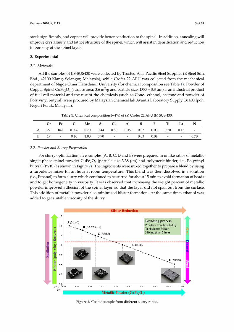
For slurry optimization, five samples (A, B, C, D and E) were prepared in unlike ratios of metallicsingle-phase spinel powder CuFe2O4 (particle size 3.38 µm) and polymeric binder, i.e., Polyvinylbutyral (PVB) (as shown in Figure 2). The ingredients were mixed together to prepare a blend by usinga turbulence mixer for an hour at room temperature. This blend was then dissolved in a solution(i.e., Ethanol) to form slurry which continued to be stirred for about 15 min to avoid formation of beadsand to get homogeneity in viscosity. It was observed that increasing the weight percent of metallicpowder improved adhesion of the spinel layer, so that the layer did not spall out from the surface.This addition of metallic powder also minimized blister formation. At the same time, ethanol wasadded to get suitable viscosity of the slurry.
Processes 2020, 8, x FOR PEER REVIEW 4 of 14
Figure 2. Coated sample from different slurry ratios.
2.3. Coating and Drying
For the coating, small pieces of Crofer 22 APU and SUS 430 were prepared in a dimension of 20 mm × 20 mm × 2 mm. These pieces were initially grinded by 120 grit and later polished over 1200 grit sandpaper to have a fine and smooth surface. Before coating, these pieces were cleaned in acetone solution and then gently immersed in the prepared slurry. After that samples were hanged for a few seconds for the removal of excess material. For the drying process, coated samples were left in the open air for 4 h and then placed in an oven for 2 h at 70 °C for the removal of volatile species. Heating began with a rate of 0.26 °C/min in a tube furnace where samples were placed in a reduced environment (5% hydrogen and 95% nitrogen) at 800 °C and were soaked for 120 min. After the tube furnace, samples were placed in a box furnace and heated in open-air atmosphere for 2 h at constant temperature and lastly annealed for 6 h in the box furnace (Figure 3 is representing heating and cooling of samples)
Figure 3. Temperature vs. time cycle of annealed samples after coating.
Figure 2. Coated sample from different slurry ratios.

Processes 2020, 8, 1113 4 of 14
2.3. Coating and Drying
For the coating, small pieces of Crofer 22 APU and SUS 430 were prepared in a dimension of20 mm × 20 mm × 2 mm. These pieces were initially grinded by 120 grit and later polished over1200 grit sandpaper to have a fine and smooth surface. Before coating, these pieces were cleaned inacetone solution and then gently immersed in the prepared slurry. After that samples were hanged fora few seconds for the removal of excess material. For the drying process, coated samples were leftin the open air for 4 h and then placed in an oven for 2 h at 70 C for the removal of volatile species.Heating began with a rate of 0.26 C/min in a tube furnace where samples were placed in a reducedenvironment (5% hydrogen and 95% nitrogen) at 800 C and were soaked for 120 min. After the tubefurnace, samples were placed in a box furnace and heated in open-air atmosphere for 2 h at constanttemperature and lastly annealed for 6 h in the box furnace (Figure 3 is representing heating and coolingof samples)
Processes 2020, 8, x FOR PEER REVIEW 4 of 14
Figure 2. Coated sample from different slurry ratios.
2.3. Coating and Drying
For the coating, small pieces of Crofer 22 APU and SUS 430 were prepared in a dimension of 20 mm × 20 mm × 2 mm. These pieces were initially grinded by 120 grit and later polished over 1200 grit sandpaper to have a fine and smooth surface. Before coating, these pieces were cleaned in acetone solution and then gently immersed in the prepared slurry. After that samples were hanged for a few seconds for the removal of excess material. For the drying process, coated samples were left in the open air for 4 h and then placed in an oven for 2 h at 70 °C for the removal of volatile species. Heating began with a rate of 0.26 °C/min in a tube furnace where samples were placed in a reduced environment (5% hydrogen and 95% nitrogen) at 800 °C and were soaked for 120 min. After the tube furnace, samples were placed in a box furnace and heated in open-air atmosphere for 2 h at constant temperature and lastly annealed for 6 h in the box furnace (Figure 3 is representing heating and cooling of samples)
Figure 3. Temperature vs. time cycle of annealed samples after coating. Figure 3. Temperature vs. time cycle of annealed samples after coating.
2.4. Characterization
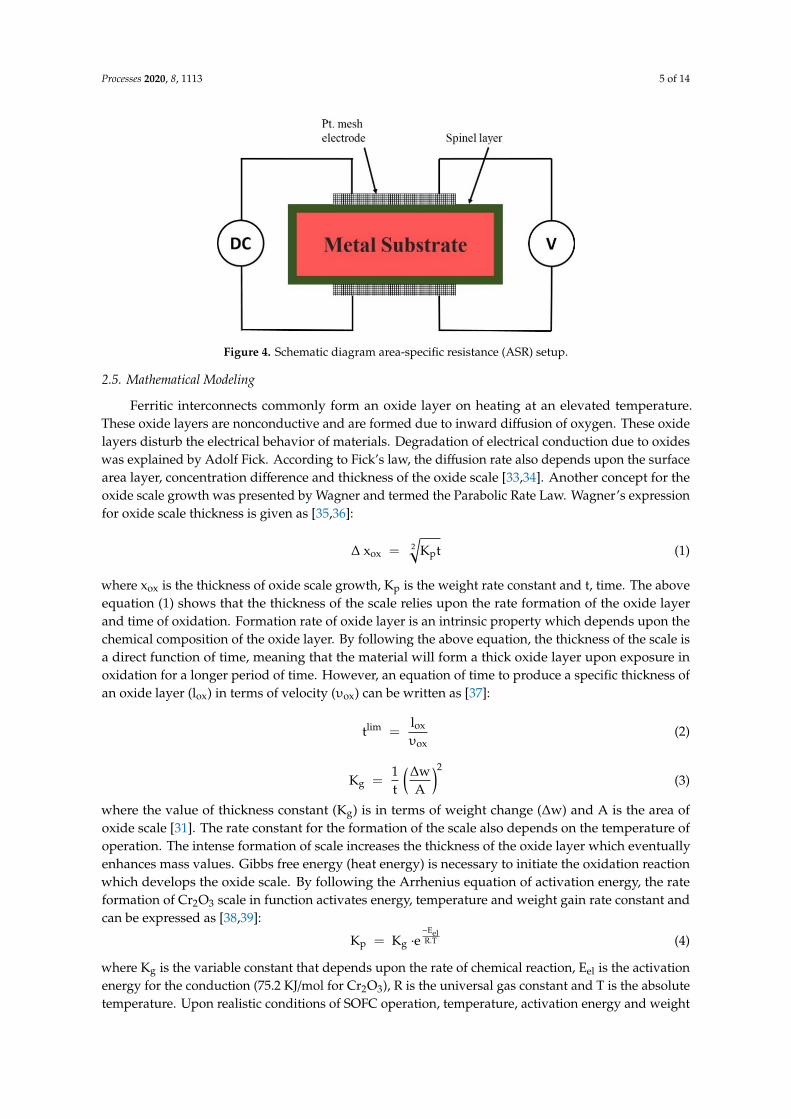
For the testing, samples were prepared according to metallography standard (ASTM E3–11).Following the SEM-imaging standard ASTM F1372–93(2020), samples were coated by gold particlesto improve conductivity. SEM ZEISS Model: EVO LS15 was used for imaging the cross-sectionalarea as well as Energy-Dispersive X-ray Spectroscopy (EDX, ZEISS Malaysia). The X-ray Diffractionmethod was used to analyze phases of spinel layers and for the study of morphological changesof the spinel. To investigate the oxidation behavior of the CuFe2O4 coated samples, the standardfour-probe method was used for ASR test against the function of time. The sample was placed inbetween Pt-mesh electrodes and Pt-paste was used at the electrode–interconnect interface for betterelectrical conduction. These electrodes were connected to the source meter Keithley 2400 (KeithleyInstruments, LLC, Washington) and then the sample holder was placed in a furnace (setup is shown inFigure 4).
Processes 2020, 8, 1113 5 of 14
Processes 2020, 8, x FOR PEER REVIEW 5 of 14
2.4. Characterization
For the testing, samples were prepared according to metallography standard (ASTM E3–11). Following the SEM-imaging standard ASTM F1372–93(2020), samples were coated by gold particles to improve conductivity. SEM ZEISS Model: EVO LS15 was used for imaging the cross-sectional area as well as Energy-Dispersive X-ray Spectroscopy (EDX, ZEISS Malaysia). The X-ray Diffraction method was used to analyze phases of spinel layers and for the study of morphological changes of the spinel. To investigate the oxidation behavior of the CuFe2O4 coated samples, the standard four-probe method was used for ASR test against the function of time. The sample was placed in between Pt-mesh electrodes and Pt-paste was used at the electrode–interconnect interface for better electrical conduction. These electrodes were connected to the source meter Keithley 2400 (Keithley Instruments, LLC, Washington) and then the sample holder was placed in a furnace (setup is shown in Figure 4).
Figure 4. Schematic diagram area-specific resistance (ASR) setup.
2.5. Mathematical Modeling
Ferritic interconnects commonly form an oxide layer on heating at an elevated temperature. These oxide layers are nonconductive and are formed due to inward diffusion of oxygen. These oxide layers disturb the electrical behavior of materials. Degradation of electrical conduction due to oxides was explained by Adolf Fick. According to Fick’s law, the diffusion rate also depends upon the surface area layer, concentration difference and thickness of the oxide scale [33,34]. Another concept for the oxide scale growth was presented by Wagner and termed the Parabolic Rate Law. Wagner’s expression for oxide scale thickness is given as [35,36]:
Δ xox = K t (1)
where xox is the thickness of oxide scale growth, Kp is the weight rate constant and t, time. The above equation (1) shows that the thickness of the scale relies upon the rate formation of the oxide layer and time of oxidation. Formation rate of oxide layer is an intrinsic property which depends upon the chemical composition of the oxide layer. By following the above equation, the thickness of the scale is a direct function of time, meaning that the material will form a thick oxide layer upon exposure in oxidation for a longer period of time. However, an equation of time to produce a specific thickness of an oxide layer (lox) in terms of velocity (υox) can be written as [37]:
tlim = (2)
Kg = (3)
where the value of thickness constant (Kg) is in terms of weight change (Δw) and A is the area of oxide scale [31]. The rate constant for the formation of the scale also depends on the temperature of operation. The intense formation of scale increases the thickness of the oxide layer which eventually
Figure 4. Schematic diagram area-specific resistance (ASR) setup.
2.5. Mathematical Modeling
Ferritic interconnects commonly form an oxide layer on heating at an elevated temperature.These oxide layers are nonconductive and are formed due to inward diffusion of oxygen. These oxidelayers disturb the electrical behavior of materials. Degradation of electrical conduction due to oxideswas explained by Adolf Fick. According to Fick’s law, the diffusion rate also depends upon the surfacearea layer, concentration difference and thickness of the oxide scale [33,34]. Another concept for theoxide scale growth was presented by Wagner and termed the Parabolic Rate Law. Wagner’s expressionfor oxide scale thickness is given as [35,36]:
∆ xox = 2√
Kpt (1)
where xox is the thickness of oxide scale growth, Kp is the weight rate constant and t, time. The aboveequation (1) shows that the thickness of the scale relies upon the rate formation of the oxide layerand time of oxidation. Formation rate of oxide layer is an intrinsic property which depends upon thechemical composition of the oxide layer. By following the above equation, the thickness of the scale isa direct function of time, meaning that the material will form a thick oxide layer upon exposure inoxidation for a longer period of time. However, an equation of time to produce a specific thickness ofan oxide layer (lox) in terms of velocity (υox) can be written as [37]:
tlim =lox
υox(2)
Kg =1t
(∆wA
)2(3)
where the value of thickness constant (Kg) is in terms of weight change (∆w) and A is the area ofoxide scale [31]. The rate constant for the formation of the scale also depends on the temperature ofoperation. The intense formation of scale increases the thickness of the oxide layer which eventuallyenhances mass values. Gibbs free energy (heat energy) is necessary to initiate the oxidation reactionwhich develops the oxide scale. By following the Arrhenius equation of activation energy, the rateformation of Cr2O3 scale in function activates energy, temperature and weight gain rate constant andcan be expressed as [38,39]:
Kp = Kg ·e−EelR.T (4)
where Kg is the variable constant that depends upon the rate of chemical reaction, Eel is the activationenergy for the conduction (75.2 KJ/mol for Cr2O3), R is the universal gas constant and T is the absolutetemperature. Upon realistic conditions of SOFC operation, temperature, activation energy and weight
Processes 2020, 8, 1113 6 of 14
gain rate constant define the thickness of the oxide scale. For this expression, thickness of oxide on thebasis of the above parameters can be written as [40]:
ξ2 =Kp
(x ρox)2 e
−EoxR.T (5)
ξ is the thickness of the oxide scale (∆ xox = ξ), x is the weight proportion of oxygen and ρox (5.22 g·cm−3
for Cr2O3) is the density of the oxide scale and Eox is the activation energy for the growth (220 KJ/molfor Cr2O3). But the area-specific resistance of the oxide scale depends on the thickness and conductivity(σox) of the oxide scale, which mathematically can be written as [38,41,42]:
ASR =ξ
σox(6)
while working in SOFC condition, the scale conduction is not uniform, as it fluctuates with thetemperature of the system which lastly affects the electrical resistance of the stack. Therefore,it is necessary to connect the temperature of operation with the conduction of scale, which canmathematically can be written as [43–45]:
σt =σox
Te(−EelR.T ) (7)
here, σox is the scale conductivity constant (3.2 × 10⁵ S/cm for Cr2O3) and σt defines the conductivityof scale at a specific temperature. For the purpose of connecting ASR with the weight gain rate,conduction of scale and temperature, Equations (5)–(7) need to be placed in an expression as,
ASR2 =Kp
(xρoxσt)2 T2e(
−Eox+2EelR.T ) (8)
where the equation defines that the ASR value of oxide scale is a function of weight gain rate constant,working temperature and conductance of oxide scale. But the equation is valid only for estimatingelectrical resistance at a certain point. To study the variation in ASR with respect to time, let it bederived by time operation, which mathematically can be written as:
d(ASR)2
dt=
Kp
(xρoxσt)2 T2e(
−Eox+2EelR.T ) (9)
which describes that the growth of the oxide scale depends upon the temperature of condition and therate formation of the scale. Working at an elevated temperature for a longer period of time increasesthe thickness of oxide layers, which not only increases the mass value but also increases resistancein the flow of electrons. Temperature also affects electrical conductance of the oxide layer. All theseparametric changes influence the area specific resistance of the interconnect material through whichthe above equation satisfies the experimental conditions of operation.
3. Results and Discussion
Crofer 22 APU and SUS 430 are metallic interconnects of SOFC which were coated by a spinellayer of CuFe2O4 for oxidation resistance. Both steels were coated by dip coating method and annealedto improve performance. The purpose of the spinel layer is to cut off air contact from the chromiumoxide layer and to inhibit the formation of the volatile layer Cr2(OH)4 so that Cr migration can bereduced. For this purpose, the spinel should have better adherence with the substrate and a densestructure that can insulate the base material from the loss of oxidation, electrical and other properties.SEM and XRD (Bruker AXS D8 advance X-Ray Diffractometer, American manufacturer) analysis wereused to study the morphological behavior of the material after heat treatment of the samples. EDS line
Processes 2020, 8, 1113 7 of 14
scanning was used to study the change in alloys concentration, weight gain effect was calculated tocheck the formation of oxide layers and a 4-probe test was conducted to study the change in electricalconduction during operational hours.
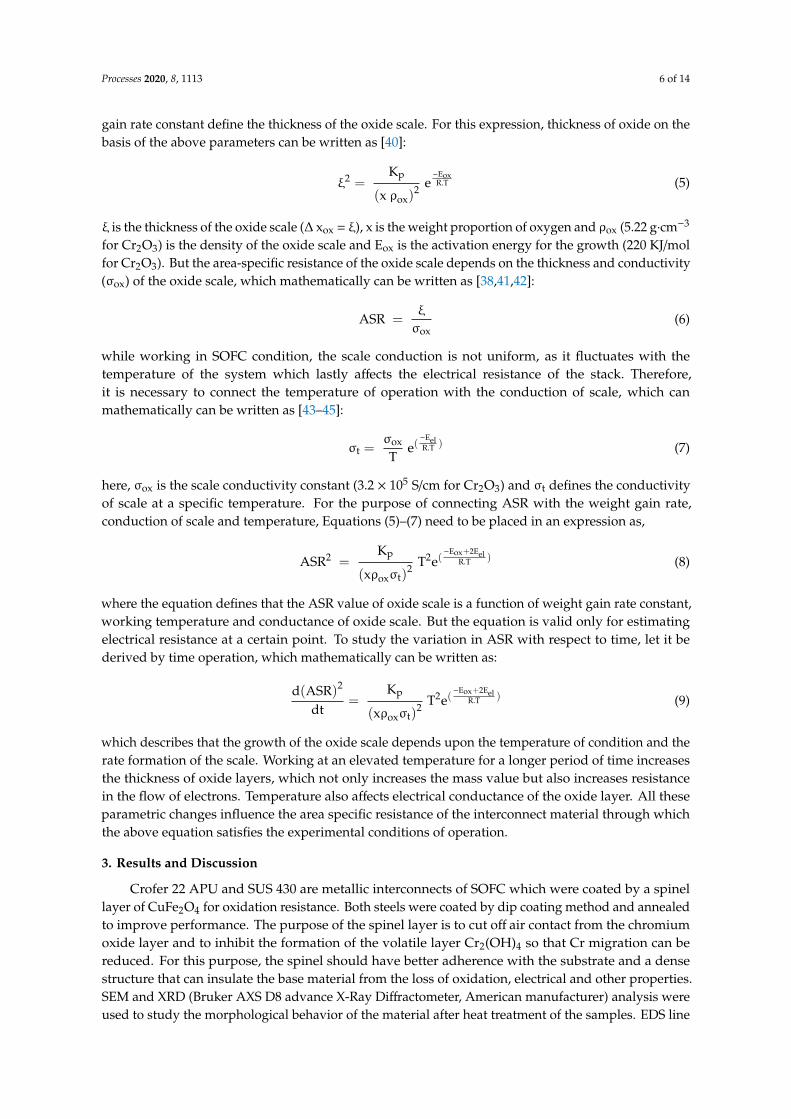
Based on the SEM images of Crofer 22 APU (Figure 5), the spinel layer was successfully fabricatedat the surface of Crofer 22 APU. From the imaging technique, it was observed that three differentlayers were formed after application of the spinel. The X-ray Diffraction pattern identified theselayers as the very first layer (L1) being the chromium oxide layer (Cr2O3), which was formed duehigh concentration of Cr in substrate. The second (L2) was the spinel protection layer, which wasintentionally produced for the reduction in chromium migration, and the third (L3) was the oxidelayer of copper (CuO) that was formed during heating in the open environment. Confirming from theresults of EDS line scanning, these layers shielded substrate material from mitigation of Cr duringformation and operation. Moreover, copper enrichment was also detected at the surface of the basematerial due to the chemical composition of the spinel.
Processes 2020, 8, x FOR PEER REVIEW 7 of 14
dense structure that can insulate the base material from the loss of oxidation, electrical and other properties. SEM and XRD (Bruker AXS D8 advance X-Ray Diffractometer, American manufacturer) analysis were used to study the morphological behavior of the material after heat treatment of the samples. EDS line scanning was used to study the change in alloys concentration, weight gain effect was calculated to check the formation of oxide layers and a 4-probe test was conducted to study the change in electrical conduction during operational hours.
Based on the SEM images of Crofer 22 APU (Figure 5), the spinel layer was successfully fabricated at the surface of Crofer 22 APU. From the imaging technique, it was observed that three different layers were formed after application of the spinel. The X-ray Diffraction pattern identified these layers as the very first layer (L1) being the chromium oxide layer (Cr2O3), which was formed due high concentration of Cr in substrate. The second (L2) was the spinel protection layer, which was intentionally produced for the reduction in chromium migration, and the third (L3) was the oxide layer of copper (CuO) that was formed during heating in the open environment. Confirming from the results of EDS line scanning, these layers shielded substrate material from mitigation of Cr during formation and operation. Moreover, copper enrichment was also detected at the surface of the base material due to the chemical composition of the spinel.
Figure 5. Results of Crofer 22 APU before and after annealing of 6 h (a,b) are SEM-Imaging, (c,d) are EDS-Line scanning and (e) is X-ray diffraction pattern, respectively.
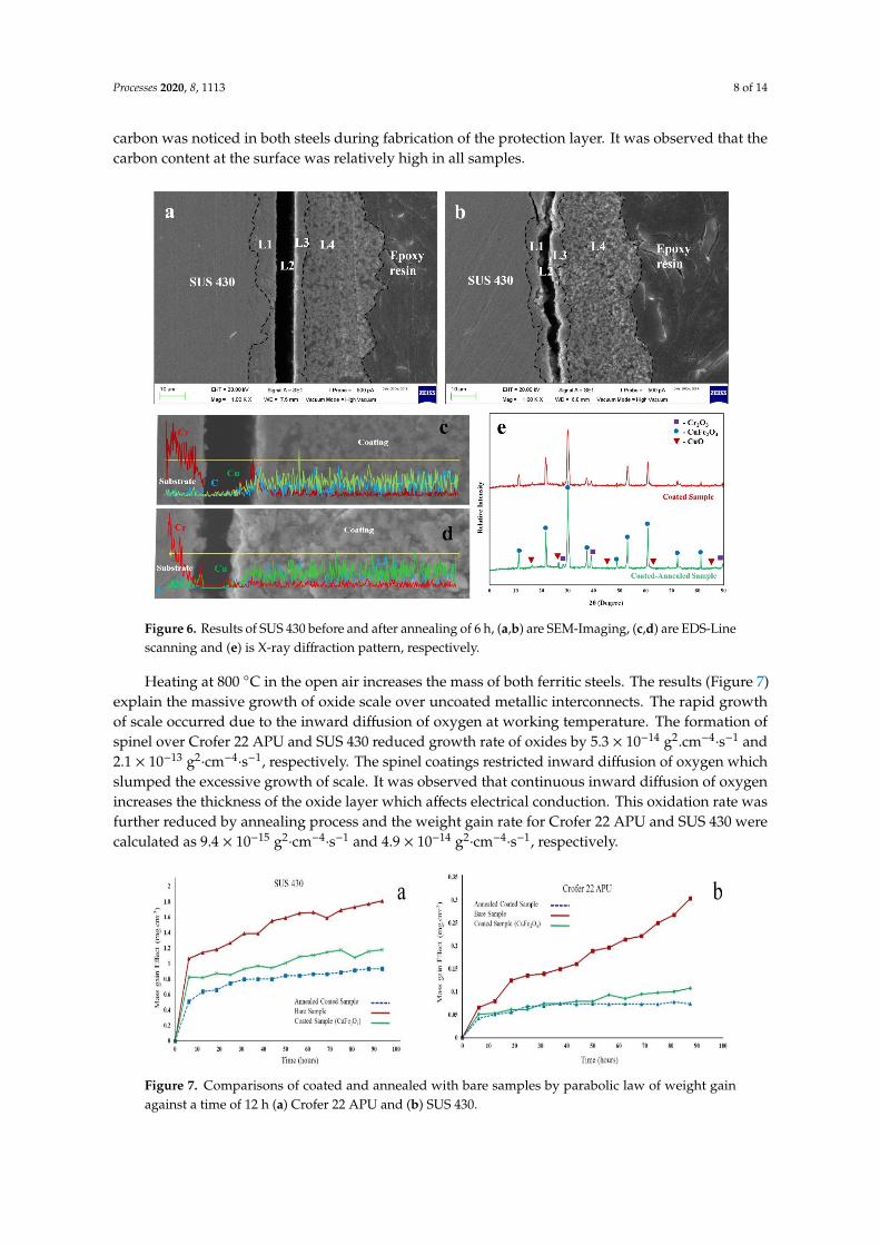
From SEM images of SUS 430 (Figure 6), it is noted that SUS 430 revealed four different layers over the base material upon fabrication of the spinel. The spinel did not spall out during working. These layers were identified by XRD peak pattern as the first (L1) and the last layer (L4) being similar to the Crofer 22 APU that contained chromium oxide (Cr2O3) and copper oxide, respectively, while the second layer (L2) contained copper, iron, chromium and magnesium oxides due to the interdiffusion of elements. The third layer (L3) was the thin spinel layer, therefore, Cu-spectrum showed inclination in EDS. EDS line scanning confirmed that the coated-SUS 430 successfully decreased mitigation of chromium and showed better performance with the spinel, but described
Figure 5. Results of Crofer 22 APU before and after annealing of 6 h (a,b) are SEM-Imaging, (c,d) areEDS-Line scanning and (e) is X-ray diffraction pattern, respectively.
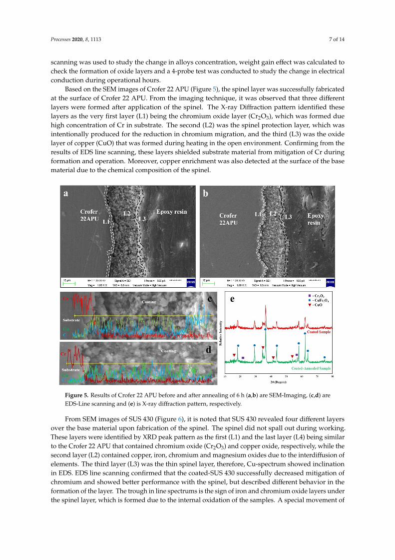
From SEM images of SUS 430 (Figure 6), it is noted that SUS 430 revealed four different layersover the base material upon fabrication of the spinel. The spinel did not spall out during working.These layers were identified by XRD peak pattern as the first (L1) and the last layer (L4) being similarto the Crofer 22 APU that contained chromium oxide (Cr2O3) and copper oxide, respectively, while thesecond layer (L2) contained copper, iron, chromium and magnesium oxides due to the interdiffusion ofelements. The third layer (L3) was the thin spinel layer, therefore, Cu-spectrum showed inclinationin EDS. EDS line scanning confirmed that the coated-SUS 430 successfully decreased mitigation ofchromium and showed better performance with the spinel, but described different behavior in theformation of the layer. The trough in line spectrums is the sign of iron and chromium oxide layers underthe spinel layer, which is formed due to the internal oxidation of the samples. A special movement of
Processes 2020, 8, 1113 8 of 14
carbon was noticed in both steels during fabrication of the protection layer. It was observed that thecarbon content at the surface was relatively high in all samples.
Processes 2020, 8, x FOR PEER REVIEW 8 of 14
different behavior in the formation of the layer. The trough in line spectrums is the sign of iron and chromium oxide layers under the spinel layer, which is formed due to the internal oxidation of the samples. A special movement of carbon was noticed in both steels during fabrication of the protection layer. It was observed that the carbon content at the surface was relatively high in all samples.
Figure 6. Results of SUS 430 before and after annealing of 6 h, (a,b) are SEM-Imaging, (c,d) are EDS-Line scanning and (e) is X-ray diffraction pattern, respectively.
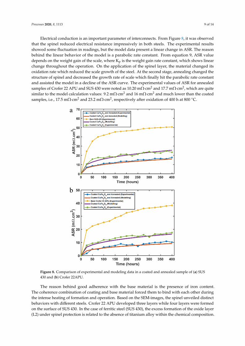
Heating at 800 °C in the open air increases the mass of both ferritic steels. The results (Figure 7) explain the massive growth of oxide scale over uncoated metallic interconnects. The rapid growth of scale occurred due to the inward diffusion of oxygen at working temperature. The formation of spinel over Crofer 22 APU and SUS 430 reduced growth rate of oxides by 5.3 × 10⁻¹⁴ g2.cm−4·s−1 and 2.1 × 10⁻¹³ g2·cm−4·s−1, respectively. The spinel coatings restricted inward diffusion of oxygen which slumped the excessive growth of scale. It was observed that continuous inward diffusion of oxygen increases the thickness of the oxide layer which affects electrical conduction. This oxidation rate was further reduced by annealing process and the weight gain rate for Crofer 22 APU and SUS 430 were calculated as 9.4 × 10⁻¹⁵ g2·cm−4·s−1 and 4.9 × 10⁻¹⁴ g2·cm−4·s−1, respectively.
Figure 6. Results of SUS 430 before and after annealing of 6 h, (a,b) are SEM-Imaging, (c,d) are EDS-Linescanning and (e) is X-ray diffraction pattern, respectively.
Heating at 800 C in the open air increases the mass of both ferritic steels. The results (Figure 7)explain the massive growth of oxide scale over uncoated metallic interconnects. The rapid growthof scale occurred due to the inward diffusion of oxygen at working temperature. The formation ofspinel over Crofer 22 APU and SUS 430 reduced growth rate of oxides by 5.3 × 10⁻¹⁴ g2.cm−4
·s−1 and2.1 × 10−13 g2
·cm−4·s−1, respectively. The spinel coatings restricted inward diffusion of oxygen which
slumped the excessive growth of scale. It was observed that continuous inward diffusion of oxygenincreases the thickness of the oxide layer which affects electrical conduction. This oxidation rate wasfurther reduced by annealing process and the weight gain rate for Crofer 22 APU and SUS 430 werecalculated as 9.4 × 10⁻¹⁵ g2
·cm−4·s−1 and 4.9 × 10⁻¹⁴ g2
·cm−4·s−1, respectively.
Processes 2020, 8, x FOR PEER REVIEW 8 of 14
different behavior in the formation of the layer. The trough in line spectrums is the sign of iron and chromium oxide layers under the spinel layer, which is formed due to the internal oxidation of the samples. A special movement of carbon was noticed in both steels during fabrication of the protection layer. It was observed that the carbon content at the surface was relatively high in all samples.
Figure 6. Results of SUS 430 before and after annealing of 6 h, (a,b) are SEM-Imaging, (c,d) are EDS-Line scanning and (e) is X-ray diffraction pattern, respectively.
Heating at 800 °C in the open air increases the mass of both ferritic steels. The results (Figure 7) explain the massive growth of oxide scale over uncoated metallic interconnects. The rapid growth of scale occurred due to the inward diffusion of oxygen at working temperature. The formation of spinel over Crofer 22 APU and SUS 430 reduced growth rate of oxides by 5.3 × 10⁻¹⁴ g2.cm−4·s−1 and 2.1 × 10⁻¹³ g2·cm−4·s−1, respectively. The spinel coatings restricted inward diffusion of oxygen which slumped the excessive growth of scale. It was observed that continuous inward diffusion of oxygen increases the thickness of the oxide layer which affects electrical conduction. This oxidation rate was further reduced by annealing process and the weight gain rate for Crofer 22 APU and SUS 430 were calculated as 9.4 × 10⁻¹⁵ g2·cm−4·s−1 and 4.9 × 10⁻¹⁴ g2·cm−4·s−1, respectively.
Figure 7. Comparisons of coated and annealed with bare samples by parabolic law of weight gainagainst a time of 12 h (a) Crofer 22 APU and (b) SUS 430.
Processes 2020, 8, 1113 9 of 14
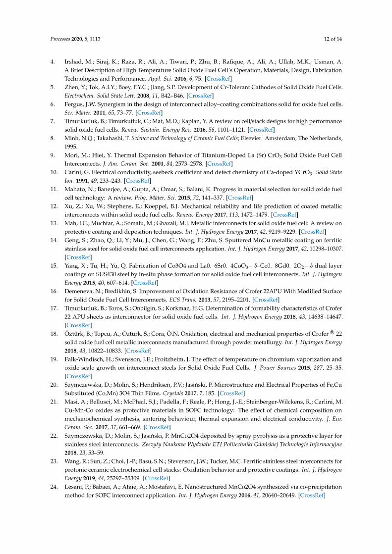
Electrical conduction is an important parameter of interconnects. From Figure 8, it was observedthat the spinel reduced electrical resistance impressively in both steels. The experimental resultsshowed some fluctuation in readings, but the model data present a linear change in ASR. The reasonbehind the linear behavior of the model is a parabolic rate constant. From equation 9, ASR valuedepends on the weight gain of the scale, where Kp is the weight gain rate constant, which shows linearchange throughout the operation. On the application of the spinel layer, the material changed itsoxidation rate which reduced the scale growth of the steel. At the second stage, annealing changed thestructure of spinel and decreased the growth rate of scale which finally hit the parabolic rate constantand assisted the model in a decline of the ASR curve. The experimental values of ASR for annealedsamples of Crofer 22 APU and SUS 430 were noted as 10.20 mΩ·cm2 and 17.7 mΩ·cm2, which are quitesimilar to the model calculation values: 9.2 mΩ·cm2 and 16 mΩ·cm2 and much lower than the coatedsamples, i.e., 17.5 mΩ·cm2 and 23.2 mΩ·cm2, respectively after oxidation of 400 h at 800 C.
Processes 2020, 8, x FOR PEER REVIEW 9 of 14
Figure 7. Comparisons of coated and annealed with bare samples by parabolic law of weight gain against a time of 12 h (a) Crofer 22 APU and (b) SUS 430.
Electrical conduction is an important parameter of interconnects. From Figure 8, it was observed that the spinel reduced electrical resistance impressively in both steels. The experimental results showed some fluctuation in readings, but the model data present a linear change in ASR. The reason behind the linear behavior of the model is a parabolic rate constant. From equation 9, ASR value depends on the weight gain of the scale, where Kp is the weight gain rate constant, which shows linear change throughout the operation. On the application of the spinel layer, the material changed its oxidation rate which reduced the scale growth of the steel. At the second stage, annealing changed the structure of spinel and decreased the growth rate of scale which finally hit the parabolic rate constant and assisted the model in a decline of the ASR curve. The experimental values of ASR for annealed samples of Crofer 22 APU and SUS 430 were noted as 10.20 mΩ·cm2 and 17.7 mΩ·cm2, which are quite similar to the model calculation values: 9.2 mΩ·cm2 and 16 mΩ·cm2 and much lower than the coated samples, i.e., 17.5 mΩ·cm2 and 23.2 mΩ·cm2, respectively after oxidation of 400 h at 800 °C.
Figure 8. Comparison of experimental and modeling data in a coated and annealed sample of (a) SUS 430 and (b) Crofer 22APU.
The reason behind good adherence with the base material is the presence of iron content. The coherence combination of coating and base material forced them to bind with each other during the intense heating of formation and operation. Based on the SEM-images, the spinel unveiled distinct behaviors with different steels. Crofer 22 APU developed three layers while four layers were formed
Figure 8. Comparison of experimental and modeling data in a coated and annealed sample of (a) SUS430 and (b) Crofer 22APU.
The reason behind good adherence with the base material is the presence of iron content.The coherence combination of coating and base material forced them to bind with each other duringthe intense heating of formation and operation. Based on the SEM-images, the spinel unveiled distinctbehaviors with different steels. Crofer 22 APU developed three layers while four layers were formedon the surface of SUS 430. In the case of ferritic steel (SUS 430), the excess formation of the oxide layer(L2) under spinel protection is related to the absence of titanium alloy within the chemical composition.

Processes 2020, 8, 1113 10 of 14
Alloy addition of titanium opposes internal oxidation during operational heating at 800 C, therefore,Crofer 22 APU did not produce an extra oxide layer. Nevertheless, the presence of a thick oxide layerdid not urge spinel to spall out and did not support Cr to leach out of the interconnect surface duringfurnace heating.
Due to molecular concentration difference of carbon in substrate and spinel, spinel showedpenetration of the carbon during environmental heating (5% hydrogen and 95% nitrogen). The reducedenvironment permits carbon to gather at the surface of the sample, which is why EDS results showedinclination of carbon at the surface. On heating in the open atmosphere at 800 C carbon leaches outof the material following the decarburization process. It is the reverse process of carburization inwhich material was heated in air at an austenizing temperature. As a result, oxygen molecules reactwith the surface’s carbon atoms and produces carbon monoxide (CO) and carbon dioxide (CO2) gaswhich then dissolve into atmosphere [46]. Both steels were heated at the same temperature under asimilar environment, but due to alloying difference of carbon within the chemical composition, SUS 430showed less diffusion of carbon as compared to Crofer 22 APU. According to the iron–carbon diagram,carbon impacts the austenizing temperature of steels, in other words, material with less carbon requireshigher temperatures to convert its structure from ferrite into austenite or vice versa [47]. By followingA3 line, it is assumed that the SUS 430 showed phase transformation into austenite earlier to Crofer 22APU which held carbon within the lattice structure of the material and did not allow carbon to diffuseout. In contrast, Crofer 22APU possesses a ferrite structure, which contains less solubility of carbon,thus allowing carbon to diffuse out from grain boundaries. Upon annealing, the spinel layer stoppedthe carbon diffusing from the substrate but it did not block diffusion from the spinel, and therefore, theline spectrum lowered carbon concentration at the surface on the annealed sample.
High porosity within the spinel layer allows more air to react with the Cr layer which increases theoxidation rate. At the same time, the porous layer increases electrical resistance during operation of thecell because of comparative high thickness and contact resistance of the spinel particles. To overcomethese problems, samples were annealed. Annealing allows the carbon to diffuse from the surface of thesample. During heating at 800 C in open atmosphere, the surface carbon atom reacted with oxygenand formed carbon monoxide and carbon dioxide gas which led to the diffusion of carbon. At the sametime, powder particles of the spinel changed their morphological behavior from fine grain to coarsemicrostructure (as shown in Figure 9). The increasing size of grains reduced the number of grainsboundaries, which eventually diminished percent porosity within the lattice. Decreasing porosityof the structure led to densification of the spinel which not only reduced the thickness of the spinellayer but also provided significant resistance in oxidation. On the basis of ASR and mass gain results,densification of the spinel through the annealing process slumps mitigation of chromium and alsoretards inward diffusion of oxygen. That is why the rate of weight gain reduced. On the other hand, theoxide layers were comparatively thick before heat treatment which defines less density of layers [48].
On combination of SEM and XRD results, it was summarized that annealing did not change thephases of layers but it did reduce the thickness of those layers. The peak of the XRD pattern shows thatthe density of the spinel increased during the annealing process while the grain size of the spinel wasalso improved, which led to the reduction in internal porosity of the spinel. Densification of the spinellayer suppressed the oxidation rate of Crofer 22 APU and SUS 430 and also supported the electricalconduction [49–51]. It brought change in density of the spinel which eventually reduced the porositypercentage of the structure, and can be expressed as [48,52]:
%Φ =m
(A × h)φp(10)
%Φ is percent porosity, m is the mass of a substance, φp is particle density, A (area) and h is thethickness of oxide layer, and particle density is the material constant. Based on the above results, it wassuggested that copper-based thin spinel performed better for electrical conduction and that annealingwas beneficial for densification of the spinel. The thinning of the spinel layer improved electrical

Processes 2020, 8, 1113 11 of 14
conduction and copper spinel, not only resolving the chromium leaching problem, but also providinga conductive layer to the interconnect [14,53,54].
Processes 2020, 8, x FOR PEER REVIEW 11 of 14
annealing was beneficial for densification of the spinel. The thinning of the spinel layer improved electrical conduction and copper spinel, not only resolving the chromium leaching problem, but also providing a conductive layer to the interconnect [14,53,54].
Figure 9. Internal mechanism observed during annealing of samples.
4. Conclusions
The following conclusion can be derived from this study:
1. The spinel (CuFe2O4) coated ferritic steel (i.e., SUS 430) is the best combination for interconnects of SOFC due to its good adherence and reduction in oxidation of chromium. The spinel not only diminished the inward diffusion of oxygen but also assisted in electrical conduction of the spinel.
2. The performance of the spinel was improved by the annealing process. Annealing reduced the thickness of the spinel and the crystallinity of oxide layer, which declined the ASR value of the coated SUS 430 by 17.7 mΩ·cm2 after 400 h oxidation at 800 °C.
3. Densification of the spinel layer by annealing proved to be the most promising manufacturing technique. It effectively dropped the percent of porosity in the spinel and decreased the mitigation of chromium significantly. Heat treatment is a satisfactory post-processing method for the production of a thin-dense protective layer.
Author Contributions: M.A.H. designed and experimented all the tests and wrote manuscript. O.B.M. assisted in experimentation design, did proof reading of manuscript and supervised this project. All authors have read and agreed to the published version of the manuscript.
Funding: The authors would like to thank Yayasan Universiti Teknologi PETRONAS (YUTP) for funding the project under the cost center 015LC0-255.
Conflicts of Interest: The authors declare that they have no known competing financial interests or personal relationships that could have appeared to influence the work reported in this paper. This study is part of scope covered in the YUTP 2020 Grant approved on 31 January 2020 under the title of “Enhancement of A Solid Oxide Fuel Cell (SOFC) Interconnect Material Stability by Eliminating the Chromium Leaching via Alloying Addition”
References
1. Zhang, X.; Chan, S.H.; Ho, H.K.; Tan, S.C.; Li, M.; Li, G.; Li, J.; Feng, Z. Towards a smart energy network: The roles of fuel/electrolysis cells and technological perspectives. Int. J. Hydrogen Energy 2015, 40, 6866–6919.
2. Choudhury, A.; Chandra, H.; Arora, A. Application of solid oxide fuel cell technology for power generation—A review. Renew. Sustain. Energy Rev. 2013, 20, 430–442.
3. Wachsman, E.; Ishihara, T.; Kilner, J. Low-temperature solid-oxide fuel cells. MRS Bull. 2014, 39, 773–779.
Figure 9. Internal mechanism observed during annealing of samples.
4. Conclusions
The following conclusion can be derived from this study:
1. The spinel (CuFe2O4) coated ferritic steel (i.e., SUS 430) is the best combination for interconnectsof SOFC due to its good adherence and reduction in oxidation of chromium. The spinel not onlydiminished the inward diffusion of oxygen but also assisted in electrical conduction of the spinel.
2. The performance of the spinel was improved by the annealing process. Annealing reduced thethickness of the spinel and the crystallinity of oxide layer, which declined the ASR value of thecoated SUS 430 by 17.7 mΩ·cm2 after 400 h oxidation at 800 C.
3. Densification of the spinel layer by annealing proved to be the most promising manufacturingtechnique. It effectively dropped the percent of porosity in the spinel and decreased the mitigationof chromium significantly. Heat treatment is a satisfactory post-processing method for theproduction of a thin-dense protective layer.
Author Contributions: M.A.H. designed and experimented all the tests and wrote manuscript. O.B.M. assisted inexperimentation design, did proof reading of manuscript and supervised this project. All authors have read andagreed to the published version of the manuscript.
Funding: The authors would like to thank Yayasan Universiti Teknologi PETRONAS (YUTP) for funding theproject under the cost center 015LC0-255.
Conflicts of Interest: The authors declare that they have no known competing financial interests or personalrelationships that could have appeared to influence the work reported in this paper. This study is part of scopecovered in the YUTP 2020 Grant approved on 31 January 2020 under the title of “Enhancement of A Solid OxideFuel Cell (SOFC) Interconnect Material Stability by Eliminating the Chromium Leaching via Alloying Addition”.
References
1. Zhang, X.; Chan, S.H.; Ho, H.K.; Tan, S.C.; Li, M.; Li, G.; Li, J.; Feng, Z. Towards a smart energy network:The roles of fuel/electrolysis cells and technological perspectives. Int. J. Hydrogen Energy 2015, 40, 6866–6919.[CrossRef]
2. Choudhury, A.; Chandra, H.; Arora, A. Application of solid oxide fuel cell technology for power generation—Areview. Renew. Sustain. Energy Rev. 2013, 20, 430–442. [CrossRef]
3. Wachsman, E.; Ishihara, T.; Kilner, J. Low-temperature solid-oxide fuel cells. MRS Bull. 2014, 39, 773–779.[CrossRef]
Processes 2020, 8, 1113 12 of 14
4. Irshad, M.; Siraj, K.; Raza, R.; Ali, A.; Tiwari, P.; Zhu, B.; Rafique, A.; Ali, A.; Ullah, M.K.; Usman, A.A Brief Description of High Temperature Solid Oxide Fuel Cell’s Operation, Materials, Design, FabricationTechnologies and Performance. Appl. Sci. 2016, 6, 75. [CrossRef]
5. Zhen, Y.; Tok, A.I.Y.; Boey, F.Y.C.; Jiang, S.P. Development of Cr-Tolerant Cathodes of Solid Oxide Fuel Cells.Electrochem. Solid State Lett. 2008, 11, B42–B46. [CrossRef]
6. Fergus, J.W. Synergism in the design of interconnect alloy–coating combinations solid for oxide fuel cells.Scr. Mater. 2011, 65, 73–77. [CrossRef]
7. Timurkutluk, B.; Timurkutluk, C.; Mat, M.D.; Kaplan, Y. A review on cell/stack designs for high performancesolid oxide fuel cells. Renew. Sustain. Energy Rev. 2016, 56, 1101–1121. [CrossRef]
8. Minh, N.Q.; Takahashi, T. Science and Technology of Ceramic Fuel Cells; Elsevier: Amsterdam, The Netherlands,1995.
9. Mori, M.; Hiei, Y. Thermal Expansion Behavior of Titanium-Doped La (Sr) CrO3 Solid Oxide Fuel CellInterconnects. J. Am. Ceram. Soc. 2001, 84, 2573–2578. [CrossRef]
10. Carini, G. Electrical conductivity, seebeck coefficient and defect chemistry of Ca-doped YCrO3. Solid StateIon. 1991, 49, 233–243. [CrossRef]
11. Mahato, N.; Banerjee, A.; Gupta, A.; Omar, S.; Balani, K. Progress in material selection for solid oxide fuelcell technology: A review. Prog. Mater. Sci. 2015, 72, 141–337. [CrossRef]
12. Xu, Z.; Xu, W.; Stephens, E.; Koeppel, B.J. Mechanical reliability and life prediction of coated metallicinterconnects within solid oxide fuel cells. Renew. Energy 2017, 113, 1472–1479. [CrossRef]
13. Mah, J.C.; Muchtar, A.; Somalu, M.; Ghazali, M.J. Metallic interconnects for solid oxide fuel cell: A review onprotective coating and deposition techniques. Int. J. Hydrogen Energy 2017, 42, 9219–9229. [CrossRef]
14. Geng, S.; Zhao, Q.; Li, Y.; Mu, J.; Chen, G.; Wang, F.; Zhu, S. Sputtered MnCu metallic coating on ferriticstainless steel for solid oxide fuel cell interconnects application. Int. J. Hydrogen Energy 2017, 42, 10298–10307.[CrossRef]
15. Yang, X.; Tu, H.; Yu, Q. Fabrication of Co3O4 and La0. 6Sr0. 4CoO3− δ–Ce0. 8Gd0. 2O2− δ dual layercoatings on SUS430 steel by in-situ phase formation for solid oxide fuel cell interconnects. Int. J. HydrogenEnergy 2015, 40, 607–614. [CrossRef]
16. Demeneva, N.; Bredikhin, S. Improvement of Oxidation Resistance of Crofer 22APU With Modified Surfacefor Solid Oxide Fuel Cell Interconnects. ECS Trans. 2013, 57, 2195–2201. [CrossRef]
17. Timurkutluk, B.; Toros, S.; Onbilgin, S.; Korkmaz, H.G. Determination of formability characteristics of Crofer22 APU sheets as interconnector for solid oxide fuel cells. Int. J. Hydrogen Energy 2018, 43, 14638–14647.[CrossRef]
18. Öztürk, B.; Topcu, A.; Öztürk, S.; Cora, Ö.N. Oxidation, electrical and mechanical properties of Crofer ® 22solid oxide fuel cell metallic interconnects manufactured through powder metallurgy. Int. J. Hydrogen Energy2018, 43, 10822–10833. [CrossRef]
19. Falk-Windisch, H.; Svensson, J.E.; Froitzheim, J. The effect of temperature on chromium vaporization andoxide scale growth on interconnect steels for Solid Oxide Fuel Cells. J. Power Sources 2015, 287, 25–35.[CrossRef]
20. Szymczewska, D.; Molin, S.; Hendriksen, P.V.; Jasinski, P. Microstructure and Electrical Properties of Fe,CuSubstituted (Co,Mn) 3O4 Thin Films. Crystals 2017, 7, 185. [CrossRef]
21. Masi, A.; Bellusci, M.; McPhail, S.J.; Padella, F.; Reale, P.; Hong, J.-E.; Steinberger-Wilckens, R.; Carlini, M.Cu-Mn-Co oxides as protective materials in SOFC technology: The effect of chemical composition onmechanochemical synthesis, sintering behaviour, thermal expansion and electrical conductivity. J. Eur.Ceram. Soc. 2017, 37, 661–669. [CrossRef]
22. Szymczewska, D.; Molin, S.; Jasinski, P. MnCo2O4 deposited by spray pyrolysis as a protective layer forstainless steel interconnects. Zeszyty Naukowe Wydziału ETI Politechniki Gdanskiej Technologie Informacyjne2018, 23, 53–59.
23. Wang, R.; Sun, Z.; Choi, J.-P.; Basu, S.N.; Stevenson, J.W.; Tucker, M.C. Ferritic stainless steel interconnects forprotonic ceramic electrochemical cell stacks: Oxidation behavior and protective coatings. Int. J. HydrogenEnergy 2019, 44, 25297–25309. [CrossRef]
24. Lesani, P.; Babaei, A.; Ataie, A.; Mostafavi, E. Nanostructured MnCo2O4 synthesized via co-precipitationmethod for SOFC interconnect application. Int. J. Hydrogen Energy 2016, 41, 20640–20649. [CrossRef]
Processes 2020, 8, 1113 13 of 14
25. Jia, C.; Wang, Y.; Molin, S.; Zhang, Y.; Chen, M.; Han, M. High temperature oxidation behavior of SUS430SOFC interconnects with Mn-Co spinel coating in air. J. Alloys Compd. 2019, 787, 1327–1335. [CrossRef]
26. Xiao, J.; Zhang, W.; Xiong, C.; Chi, B.; Pu, J.; Jian, L. Oxidation of MnCu 0.5 Co 1.5 O 4 spinel coated SUS430alloy interconnect in anode and cathode atmospheres for intermediate temperature solid oxide fuel cell. Int.J. Hydrogen Energy 2015, 40, 1868–1876. [CrossRef]
27. Tan, K.; Rahman, H.; Taib, H. Coating layer and influence of transition metal for ferritic stainless steelinterconnector solid oxide fuel cell: A review. Int. J. Hydrogen Energy 2019, 44, 30591–30605. [CrossRef]
28. Ranjbar-Nouri, Z.; Soltanieh, M.; Rastegari, S. Applying the protective CuMn2O4 spinel coating on AISI-430ferritic stainless steel used as solid oxide fuel cell interconnects. Surf. Coatings Technol. 2018, 334, 365–372.[CrossRef]
29. Wu, Y. Metal Oxides in Energy Technologies; Elsevier: Amsterdam, The Netherlands, 2018.30. Xu, Y.; Wen, Z.; Wang, S.; Wen, T. Cu doped Mn–Co spinel protective coating on ferritic stainless steels for
SOFC interconnect applications. Solid State Ion. 2011, 192, 561–564. [CrossRef]31. Geng, S.; Pan, Y.; Chen, G.; Wang, F. CuFe2O4 protective and electrically conductive coating thermally
converted from sputtered CuFe alloy layer on SUS 430 stainless steel interconnect. Int. J. Hydrogen Energy2019, 44, 9400–9407. [CrossRef]
32. Pan, Y.; Geng, S.; Chen, G.; Wang, F. Effect of pre-oxidation on surface scale microstructure and electricalproperty of Cu-Fe coated steel interconnect. Corros. Sci. 2020, 170, 108680. [CrossRef]
33. Sundén, B.; Faghri, M. Transport Phenomena in Fuel Cells; WIT Press: Boston, MA, USA, 2005; Volume 19.34. Zhao, T.; Xu, C.; Chen, R.; Yang, W. Mass transport phenomena in direct methanol fuel cells. Prog. Energy
Combust. Sci. 2009, 35, 275–292. [CrossRef]35. Kutz, M. Handbook of Environmental Degradation of Materials; William Andrew: New York, NY, USA, 2018.36. Badini, C.; Laurella, F. Oxidation of FeCrAl alloy: Influence of temperature and atmosphere on scale growth
rate and mechanism. Surf. Coatings Technol. 2001, 135, 291–298. [CrossRef]37. Kulikovsky, A. A Model for Cr Poisoning of SOFC Cathode. J. Electrochem. Soc. 2011, 158, B253. [CrossRef]38. Gupta, S.; Wang, J. Proceedings of the 41st International Conference on Advanced Ceramics and Composites;
John Wiley & Sons: Hoboken, NJ, USA, 2018; Volume 614.39. Callister, W.D.; Rethwisch, D.G. Materials Science and Engineering; John wiley & Sons: New York, NY, USA,
2011; Volume 5.40. Hauffe, K. Oxidation of Metals; Plenum Press: New York, NY, USA, 1965.41. Lee, C.; Bae, J. Oxidation-resistant thin film coating on ferritic stainless steel by sputtering for solid oxide
fuel cells. Thin Solid Films 2008, 516, 6432–6437. [CrossRef]42. Jimenez, C.A. Effect of Composition, Microstructure and Component Thickness on the Oxidation Behaviour of Laves
Phase Strengthened Interconnect Steel for Solid Oxide Fuel Cells (SOFC); Forschungszentrum Jülich: Berlin,Germany, 2014; Volume 204.
43. Paknahad, P.; Askari, M.; Ghorbanzadeh, M. Application of sol–gel technique to synthesis of copper–cobaltspinel on the ferritic stainless steel used for solid oxide fuel cell interconnects. J. Power Sources 2014, 266,79–87. [CrossRef]
44. Leah, R.; Brandon, N.; Aguiar, P. Modelling of cells, stacks and systems based around metal-supported planarIT-SOFC cells with CGO electrolytes operating at 500–600 C. J. Power Sour. 2005, 145, 336–352. [CrossRef]
45. Xiao, J.; Zhang, W.; Xiong, C.; Chi, B.; Pu, J.; Jian, L. Oxidation behavior of Cu-doped MnCo2O4 spinelcoating on ferritic stainless steels for solid oxide fuel cell interconnects. Int. J. Hydrogen Energy 2016, 41,9611–9618. [CrossRef]
46. Hong, L.-K.; Cheng, R.; Ai, L.-Q.; Sun, C.-J. Mechanism of Carbon Diffusion in the Iron Sheet DuringGas–Solid Decarburization. Trans. Indian Inst. Met. 2018, 72, 335–342. [CrossRef]
47. von Goldbeck, O.K. Iron—Carbon Fe—C. In IRON—Binary Phase Diagrams; Springer: Berlin, Germany, 1982;pp. 23–26.
48. Visconti, G. Fundamentals of Physics and Chemistry of the Atmosphere; Springer: Berlin, Germany, 2001.49. Brown, E.R. Relationship of Air Voids, Lift Thickness, and Permeability in Hot Mix Asphalt Pavements; Transportation
Research Board, The National Academies of Science Engineering Medicine: Washington, DC, USA, 2004;Volume 531.
50. Fang, Y.; Wu, C.; Duan, X.; Wang, S.; Chen, Y. High-temperature oxidation process analysis of MnCo2O4
coating on Fe–21Cr alloy. Int. J. Hydrogen Energy 2011, 36, 5611–5616. [CrossRef]

Processes 2020, 8, 1113 14 of 14
51. Ou, D.R.; Cheng, M.; Wang, X.-L. Development of low-temperature sintered Mn–Co spinel coatings onFe–Cr ferritic alloys for solid oxide fuel cell interconnect applications. J. Power Sources 2013, 236, 200–206.[CrossRef]
52. Brewer, C.E.; Chuang, V.J.; Masiello, C.A.; Gonnermann, H.; Gao, X.; Dugan, B.; Driver, L.E.; Panzacchi, P.;Zygourakis, K.; Davies, C.A. New approaches to measuring biochar density and porosity. Biomass Bioenergy2014, 66, 176–185. [CrossRef]
53. Brylewski, T.; Kruk, A.; Bobruk, M.; Adamczyk, A.; Partyka, J.; Rutkowski, P. Structure and electrical propertiesof Cu-doped Mn-Co-O spinel prepared via soft chemistry and its application in intermediate-temperaturesolid oxide fuel cell interconnects. J. Power Sour. 2016, 333, 145–155. [CrossRef]
54. Joshi, S.; Petric, A. Nickel substituted CuMn2O4 spinel coatings for solid oxide fuel cell interconnects. Int. J.Hydrogen Energy 2017, 42, 5584–5589. [CrossRef]
© 2020 by the authors. Licensee MDPI, Basel, Switzerland. This article is an open accessarticle distributed under the terms and conditions of the Creative Commons Attribution(CC BY) license (http://creativecommons.org/licenses/by/4.0/).