Embed Size (px)
Citation preview

Ind
ust
rial E
lectr
ical En
gin
eerin
g a
nd
A
uto
matio
n
CODEN:LUTEDX/(TEIE-5394)/1-95(2017)
Mitigation of flux produced bygeomagnetically induced currents(GIC) on power transformers withdelta windings
Henrik JönssonVictor Lovén
Division of Industrial Electrical Engineering and Automation Faculty of Engineering, Lund University

Mitigation of flux produced by geomagnetically
induced currents (GIC) on power transformers with
delta windings
June 19, 2017
Abstract
Geomagnetically induced currents (GIC) arise in our power system due to fluctuationsin the earths magnetic field, which commonly is caused by space weather events. Thesecurrents may result in core saturation for transformers that get exposed. The purposeof this project is to clarify the possibility of reconnecting the delta connected tertiarywindings in order to mitigate the saturation that is caused due to GIC. Laboratorystudies were performed on different types of transformers, which later were simulated andcompared to the experimental results, in order to verify the credibility of the simulations.This will allow us to trust the results of the simulations performed on a large transformerto a greater extent.

Acknowledgements
This thesis would not have be possible without the help provided by our supervi-sor Olof Samuelsson, and the examiner Avo Reinap. We would also like to thank theemployees at IEA, especially Johan Bjornstedt and Getachew Drage, for answering ques-tions and providing ideas when needed. The authors would also like to aim a specialthanks to David Boteler at NRCan for the supervision and guidance during our studiesat NRCan, Ottawa, Ontario, Canada. We would also like to thank Sebastian Guillonfor the information we gained during our visit at Hydro Quebec, Montreal, Quebec,Canada. Finally, the authors would like to thanks AForsk for the scholarship whichfinanced the visit to NRcan, Ottawa, Ontario, Canada.
Contents
1 Introduction 51.1 Background . . . . . . . . . . . . . . . . . . . . . . . . . . . . . . . . . . 51.2 Purpose . . . . . . . . . . . . . . . . . . . . . . . . . . . . . . . . . . . . 51.3 Scope of work . . . . . . . . . . . . . . . . . . . . . . . . . . . . . . . . . 5
2 Theory 72.1 Geomagnetically induced currents, GIC . . . . . . . . . . . . . . . . . . 7
2.1.1 Cause . . . . . . . . . . . . . . . . . . . . . . . . . . . . . . . . . 72.1.2 Geomagnetic induction . . . . . . . . . . . . . . . . . . . . . . . 82.1.3 Effect . . . . . . . . . . . . . . . . . . . . . . . . . . . . . . . . . 9
2.2 Zero sequence currents . . . . . . . . . . . . . . . . . . . . . . . . . . . . 112.3 Mitigation Method . . . . . . . . . . . . . . . . . . . . . . . . . . . . . . 12
2.3.1 Series capacitance . . . . . . . . . . . . . . . . . . . . . . . . . . 122.3.2 Transformer type . . . . . . . . . . . . . . . . . . . . . . . . . . . 122.3.3 Compensation windings for GIC immunity . . . . . . . . . . . . 132.3.4 Partial compensation with tertiary windings . . . . . . . . . . . . 142.3.5 Closing open delta with a capacitor . . . . . . . . . . . . . . . . 14
3 Equipment 163.1 Measuring equipment . . . . . . . . . . . . . . . . . . . . . . . . . . . . 163.2 Transformers . . . . . . . . . . . . . . . . . . . . . . . . . . . . . . . . . 173.3 AC supply to transformers . . . . . . . . . . . . . . . . . . . . . . . . . . 19
3.3.1 Public 230V grid . . . . . . . . . . . . . . . . . . . . . . . . . . . 193.3.2 Public 230V grid and Variac . . . . . . . . . . . . . . . . . . . . 203.3.3 From 127V grid to variac to step up transformer . . . . . . . . . 213.3.4 200kV A synchronous generator . . . . . . . . . . . . . . . . . . . 22
3.4 Power supply and load . . . . . . . . . . . . . . . . . . . . . . . . . . . . 23
4 Experiments - steady state 244.1 Hysteresis curve for transformers . . . . . . . . . . . . . . . . . . . . . . 244.2 GIC impact in transformers . . . . . . . . . . . . . . . . . . . . . . . . . 24
4.2.1 Single phase transformers . . . . . . . . . . . . . . . . . . . . . . 254.2.2 Three-legged transformer . . . . . . . . . . . . . . . . . . . . . . 264.2.3 Five-legged transformer . . . . . . . . . . . . . . . . . . . . . . . 274.2.4 Harmonics in transformers without GIC . . . . . . . . . . . . . . 27
4.3 GIC mitigation in transformers . . . . . . . . . . . . . . . . . . . . . . . 284.3.1 Single phase transformers with compensation winding . . . . . . 294.3.2 Three-legged 3-phase transformer with compensation winding . . 324.3.3 Five-legged transformer with compensation winding . . . . . . . 33
4.4 Comparison . . . . . . . . . . . . . . . . . . . . . . . . . . . . . . . . . . 354.4.1 Single phase transformer . . . . . . . . . . . . . . . . . . . . . . . 35
1
4.4.2 Three legged 3-phase transformer . . . . . . . . . . . . . . . . . . 364.4.3 Five legged 3-phase transformer . . . . . . . . . . . . . . . . . . . 37
5 Experiments - transients 395.1 GIC step response . . . . . . . . . . . . . . . . . . . . . . . . . . . . . . 39
5.1.1 Without GIC mitigation windings . . . . . . . . . . . . . . . . . 405.1.2 With GIC mitigation windings . . . . . . . . . . . . . . . . . . . 425.1.3 With reversed GIC mitigation windings . . . . . . . . . . . . . . 435.1.4 Summary . . . . . . . . . . . . . . . . . . . . . . . . . . . . . . . 44
5.2 One phase GIC step response . . . . . . . . . . . . . . . . . . . . . . . . 445.2.1 Without GIC mitigation winding . . . . . . . . . . . . . . . . . . 445.2.2 With GIC mitigation winding . . . . . . . . . . . . . . . . . . . . 455.2.3 With reversed GIC mitigation winding . . . . . . . . . . . . . . . 46
5.3 3-phase GIC step response with delta connected tertiary windings . . . 475.3.1 No delta windings . . . . . . . . . . . . . . . . . . . . . . . . . . 485.3.2 31 Volt delta windings . . . . . . . . . . . . . . . . . . . . . . . . 495.3.3 Flux measurements over unconnected winding . . . . . . . . . . . 50
6 Experiment results 526.1 GIC impact on system . . . . . . . . . . . . . . . . . . . . . . . . . . . . 52
6.1.1 Single phase transformers . . . . . . . . . . . . . . . . . . . . . . 526.1.2 Three-legged transformer . . . . . . . . . . . . . . . . . . . . . . 526.1.3 Five-legged transformer . . . . . . . . . . . . . . . . . . . . . . . 53
6.2 GIC mitigation . . . . . . . . . . . . . . . . . . . . . . . . . . . . . . . . 536.2.1 Single phase transformers . . . . . . . . . . . . . . . . . . . . . . 546.2.2 Three-legged transformer . . . . . . . . . . . . . . . . . . . . . . 546.2.3 Five-legged transformer . . . . . . . . . . . . . . . . . . . . . . . 54
6.3 Summary of steady state . . . . . . . . . . . . . . . . . . . . . . . . . . . 546.4 Step response without compensation windings . . . . . . . . . . . . . . . 556.5 Step response with compensation windings . . . . . . . . . . . . . . . . . 566.6 Step response with delta connected tertiary windings . . . . . . . . . . . 576.7 Summary of step response . . . . . . . . . . . . . . . . . . . . . . . . . . 57
7 Simulations 587.1 Model . . . . . . . . . . . . . . . . . . . . . . . . . . . . . . . . . . . . . 587.2 Simulations . . . . . . . . . . . . . . . . . . . . . . . . . . . . . . . . . . 58
7.2.1 2kVA . . . . . . . . . . . . . . . . . . . . . . . . . . . . . . . . . 597.2.2 Lower inductance on supply grid . . . . . . . . . . . . . . . . . . 637.2.3 Transient behaviour . . . . . . . . . . . . . . . . . . . . . . . . . 647.2.4 400MVA 130/400kV . . . . . . . . . . . . . . . . . . . . . . . . . 667.2.5 Transient behaviour . . . . . . . . . . . . . . . . . . . . . . . . . 70
7.3 Summary . . . . . . . . . . . . . . . . . . . . . . . . . . . . . . . . . . . 72
8 Simulation results 738.1 Without GIC . . . . . . . . . . . . . . . . . . . . . . . . . . . . . . . . . 738.2 GIC without mitigation . . . . . . . . . . . . . . . . . . . . . . . . . . . 738.3 GIC with perfect mitigation . . . . . . . . . . . . . . . . . . . . . . . . . 738.4 GIC with partial mitigation . . . . . . . . . . . . . . . . . . . . . . . . . 748.5 Grid impedance . . . . . . . . . . . . . . . . . . . . . . . . . . . . . . . . 748.6 Transient behaviour . . . . . . . . . . . . . . . . . . . . . . . . . . . . . 74
2
9 Conclusions 759.1 GIC Effects . . . . . . . . . . . . . . . . . . . . . . . . . . . . . . . . . . 75
9.1.1 Experimental conclusions . . . . . . . . . . . . . . . . . . . . . . 759.1.2 Simulation conclusions . . . . . . . . . . . . . . . . . . . . . . . . 759.1.3 Summary of GIC effects . . . . . . . . . . . . . . . . . . . . . . . 76
9.2 GIC Mitigation . . . . . . . . . . . . . . . . . . . . . . . . . . . . . . . . 769.2.1 Experimental conclusions . . . . . . . . . . . . . . . . . . . . . . 769.2.2 Simulation conclusions . . . . . . . . . . . . . . . . . . . . . . . . 779.2.3 Summary of GIC mitigation . . . . . . . . . . . . . . . . . . . . . 77
9.3 Transient behaviour . . . . . . . . . . . . . . . . . . . . . . . . . . . . . 779.3.1 Delta windings . . . . . . . . . . . . . . . . . . . . . . . . . . . . 789.3.2 Mitigation windings . . . . . . . . . . . . . . . . . . . . . . . . . 789.3.3 Conclusions of transients . . . . . . . . . . . . . . . . . . . . . . 78
9.4 Harmonics . . . . . . . . . . . . . . . . . . . . . . . . . . . . . . . . . . . 78
10 Future Work 80
Appendices 84
A Middle step between 2.4kVA 230/127kV and 400MV 130/400kV trans-formers 85
A.0.1 400MVA 400/230kV . . . . . . . . . . . . . . . . . . . . . . . . . 85
B List of material 90
3
List of symbols
ε Electromotive force, EMF
R1 Resistance in series with battery
R2 Resistance in parallel with battery and R1
Φ Magnetic flux
Ugic Battery voltage representing GIC
L Inductance between breaker and load transformer
ZN Wire inductance and resistance between compensation windings and ground
α GIC rise time for an uncompensated transformer
β Amount of compensation
Terminology
AC Alternating Current
CME Coronal Mass Ejection
DC Direct Current
EMF Electromotive Force
FFT Fast Fourier Transform
GIC Geomagnetically Induced Currents
GMD Geomagnetic Disturbance
MMF Magnetomotive Force
Primary winding wye connected winding to which the power supply is connected to
rms Root Mean Square
Secondary winding wye connected winding which is the side of the transformer thatis loaded.
SVC Static Var Compensator
Tertiary winding Delta connected tertiary winding
Compensation winding Open delta connected tertiary windings, with one end con-nected to secondary zero and the other to ground.
p.u Per unit
4
Chapter 1
Introduction
1.1 Background
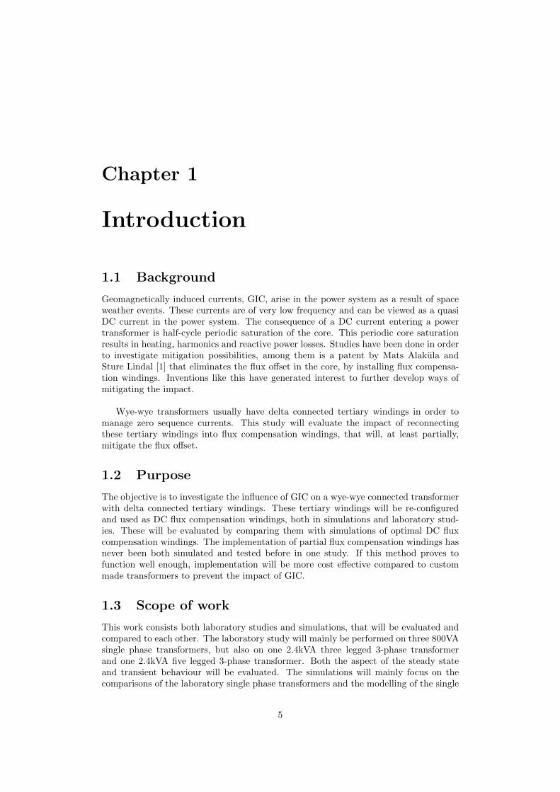
Geomagnetically induced currents, GIC, arise in the power system as a result of spaceweather events. These currents are of very low frequency and can be viewed as a quasiDC current in the power system. The consequence of a DC current entering a powertransformer is half-cycle periodic saturation of the core. This periodic core saturationresults in heating, harmonics and reactive power losses. Studies have been done in orderto investigate mitigation possibilities, among them is a patent by Mats Alakula andSture Lindal [1] that eliminates the flux offset in the core, by installing flux compensa-tion windings. Inventions like this have generated interest to further develop ways ofmitigating the impact.
Wye-wye transformers usually have delta connected tertiary windings in order tomanage zero sequence currents. This study will evaluate the impact of reconnectingthese tertiary windings into flux compensation windings, that will, at least partially,mitigate the flux offset.
1.2 Purpose
The objective is to investigate the influence of GIC on a wye-wye connected transformerwith delta connected tertiary windings. These tertiary windings will be re-configuredand used as DC flux compensation windings, both in simulations and laboratory stud-ies. These will be evaluated by comparing them with simulations of optimal DC fluxcompensation windings. The implementation of partial flux compensation windings hasnever been both simulated and tested before in one study. If this method proves tofunction well enough, implementation will be more cost effective compared to custommade transformers to prevent the impact of GIC.
1.3 Scope of work
This work consists both laboratory studies and simulations, that will be evaluated andcompared to each other. The laboratory study will mainly be performed on three 800VAsingle phase transformers, but also on one 2.4kVA three legged 3-phase transformerand one 2.4kVA five legged 3-phase transformer. Both the aspect of the steady stateand transient behaviour will be evaluated. The simulations will mainly focus on thecomparisons of the laboratory single phase transformers and the modelling of the single
5
phase transformers in order to achieve a reliable simulation model that can be up-sizedto a 400MVA transformer.
6
Chapter 2
Theory
This chapter deals with the theory of the how geomagnetically induced currents (GIC)enters the power system and some theory about the system. First, a brief introductionon space weather disturbances and how these cause geomagnetic disturbances. Furtherthe GIC in the power grids are discussed. Followed by the negative effects GIC have onthe power system and in particular on high power transformers.
2.1 Geomagnetically induced currents, GIC
GICs are low frequency currents, which are induced in power systems by geomagneticfield variations that are a result of space weather disturbances. The frequency is solow, compared to the frequency of the power grid, that it can be considered as quasi-DC. This phenomenon was first noticed over 150 years ago, when the telegraph systemwas effected by GIC [2]. Back then this was the most advanced infrastructure and thisdisturbance resulted in massive problems. Today, in our current, complex power system,these geomagnetic field variations can still cause huge problems as this report will show.
2.1.1 Cause
Solar activity The cause of GIC are solar storms and space weather events. Theseevents start at the surface of the sun when the suns magnetic fields collide and largeclouds of plasma are thrown out in to space. These clouds of plasma do sometime travelin the direction of Earth. Depending on the direction of the magnetic field inside thecloud of plasma it has different impact on our magnetosphere. This can generate electricfields which drives an electric current between the magnetosphere and the ionosphere.Due to the orientation of the earths magnetic field the currents are most intense inthe auroral ovals. Since this magnetic field changes an electric current is induced inconducting structures such as the power system [3],[4].
Charged particles heading towards earth As a solar storm erupts on the sun,particles will head out into space. Some of which will head towards earth and hit themagnetosphere. The first thing to hit us is the light that is sent out from the solar flare,as it travels with the speed of light. Shortly after that, the solar energetic particles willhit, as they are travelling close to the speed of light. However the speed of the solarenergetic particles can vary, usually it hits earth 20-30 minutes after the eruption. Thecoronal mas ejection (CME), which travels a lot slower, will hit the earth after 1-4 days.If a person would be in space and get hit by a solar storm, the particles could do greatdamage to the human body. Luckily, we are protected from these particles by the earth’s
7

magnetosphere and atmosphere. Generally, solar storms do not have any impact on thehuman body at our planet, however it can have a great negative impact on our tech-nological infrastructure. Some examples of space weather consequences on Earth is thecollapse of the Hydro-Quebec power system on March 13, 1989 due to geomagneticallyinduced currents, where over 6 million people were without power for 9 hours. Anotherexample of the impact of space weather is the power outage in Malmo, Sweden, 31st ofOctober 2003. This power outage was also due to GIC [5].
2.1.2 Geomagnetic induction
The Geomagnetic disturbance (GMD) results in GIC in the powers system, pipe linesand other long conductors. The currents are related to the magnetic field changes,which can be explained by the variation of flux Φ over time resulting in the EMF ε. SeeFaraday′s law [5].
ε = −δΦδt
In order for current induction to take place, according to Faraday’s law, the magneticfield has to vary through a closed loop. The power lines themselves do not make a loop,as all of them are vertical, slightly above the ground and the geomagnetic disturbancealso act vertically to the ground. However, the power lines do make an entire closedloop together with the earth. The upper half of the loop is represented by the powerlines, that are eventually grounded through transformers and the lower half of the loopis the earth.The magnitude of the GIC depends of different key variables: length of power lines,power line direction, the magnetic flux variation and soil conductivity.
Power line length The length of the power lines matters, as with longer lines alarger current can be induced. However, when the line length gets too long the GIC asa function of the line length reaches a steady state. This behaviour is visible in Figure2.1 [5].
8

Figure 2.1: (a) Example circuit of a transmission line connected to two substations, withgrounding at the transformer neutral points. (b) Graph of induced GIC with respect tothe length of the power lines in kilometers, [5].
Power line direction The direction of the power lines also matters, as the magnitudeof the GIC depends on the perpendicular component of the lines and the geomagneticfield variation. However, since the geomagnetic disturbances are not guaranteed to behomogeneous and straight the prediction of which power line direction that is worst canbe hard to predict.
Magnetic flux variation Finally, the magnitude of the electromagnetic field vari-ations also makes a difference on the amplitude of the GIC, larger variations inducemore current. This is also visible in Faraday’s law. In other words, larger magnitudeand higher frequency of the field results in higher induced currents. However, the Soilconductivity also impacts the amount of GIC that is induced to the system, [5].
2.1.3 Effect
The induced GIC flows along the transmission lines and to ground through the trans-former windings. This GIC produces a quasi-DC offset in the magnetization of thetransformer core which results in three primary negative effects. Transformer heating,reactive power losses and waveform distortion [8, 9]. A saturated core indirectly heatsthe transformer since the flux has to travel through other paths which are not designedto handle magnetic flux. This saturated core also results in waveform distortion (ie. in-creased harmonics) which eventually may cause misoperation of protection relays. Thewaveform distortion also increases the reactive loading of the system and can contributeto voltage collapse [9].
9

Saturation The partial core saturation occurs when the variation of magnetic fluxand current is no longer symmetric around zero, which is a result of the GIC enteringthe transformer through the power lines. With no DC-offset, the transformer is ableto work in a non-saturated area of the magnetizing characteristic, see Figure 2.2, atall points of the sinusoidal current. However when the transformer is subjected to aDC-offset, the sinusoidal current and magnetic flux will no longer be symmetric aroundzero, but instead asymmetric around the DC-offset.[9] This leads to larger current andmagnetic flux in the half period with the same current and magnetic flux direction asthe DC-offset. Hence, smaller current during the other half period. The half periodwith reduced current and magnetic flux is not a problem, however the half period withincreased current and flux may saturate the core. The core is not saturated for theentire half period, but only for the small part where the magnetic flux from the ACsource, added to the magnetic flux from the GIC is larger than the maximum flux thatthe core can handle, without getting saturated. As the core gets saturated it loses a lotof its magnetic abilities, which leads to lower inductance of the transformer, resultingin larger winding currents, in the form of current spikes [9], see Figure 2.2.
Figure 2.2: Mapping from magnetic flux to current through the magnetizing character-istic typical for a transformer but with hysteresis neglected. Operation in linear range(dashed) and with half-cycle saturation (solid) shown.[9]
As the core enters magnetic saturation it can not carry any more magnetic flux,hence the permeability of the core drops and the reluctance, which is the magneticresistance, increases. This results in the flux finding new paths outside of the corewhere the reluctance is lower. The flux will therefore flow through the transformer oil,tank, housing and nearby structures.By mitigating or fully eliminating the flux induced by the DC offset the impact ofGIC would be eliminated in the transformer [9]. There is a patent [1] that eliminatesthe flux induced by the DC offset, however this patent comes with a great economiccost, as the transformers would have to be replaced by transformers with an extrawinding that specifically eliminates the flux induced by the DC offset. As for now, wye-
10
connected transformers have delta-connected tertiary windings, which is implemented inthe transformer in order to handle zero sequence currents. These tertiary windings couldbe used to mitigate the flux induced by the DC offset, this has similarities to the patentedcompensation windings, which is also delta connected [1]. Since the number of turns ofthe tertiary windings are not optimal, the DC flux will not be completely eliminated,but if reduced enough to prevent the core from getting saturated, the negative effects ofthe GIC would disappear, or be mitigated if partially compensated.
Heating In case of saturation and the flux finds new paths outside of the transformercore, hotspots accrues in the transformer and nearby structures. The transformer oiland housing are not designed to carry AC magnetic flux which will result in eddycurrents in the structures, this will increase the temperature of the transformer. If thecore is exposed to enough DC-offset, which forces the flux out from the core, this willresult in overheating of the transformer that may cause permanent damage. A damagedtransformer will need maintenance or replacement before being put into service again.Taking a power transformer out of service will result in increased system loading duringthe time that the transformer is inoperative, which may last several days and muchlonger if the supply of nearby spears is exhausted [9].
Reactive power losses As GIC is entering the transformer, the rms value of thedistorted current waveform will increase. This increment results in higher reactive lossesin the transformer, which results in the power transformer drawing more reactive power,this stresses the system.Systems near voltage collapse are characterized by drawing great amounts of reactivepower, hence this increment brings the system closer to a blackout.
Harmonics and waveform distortion The normally sinusoidal AC current and fluxbecome distorted due to the transformer saturation produced by GIC. This distortedwaveform causes relays to operate in order to protect the system from over currents andover voltage. However, these operations can be unwanted since the relays are trippingon a distorted waveform and not the fundamental value of the peak value. In somecases, such as the Quebec blackout in 1989 and Malmo blackout in 2003, this falsetripping of relays disconnects equipment that weakens the system, such as a Static VarCompensator (SVC) or a transformer [9].
2.2 Zero sequence currents
Zero sequence currents, which are AC current components being the same in all threephases, are present when an unsymmetrical fault to ground occurs. For instance a lineto ground fault.
While ungrounded transformer windings block zero sequence current from the ter-minals, windings that are grounded, typically wye connected, can carry such current.When transformers saturate, they draw a third harmonic current, which is of zero se-quence type. Instead of drawing this current from the network, which is undesirable, itcan be supplied by delta connected windings. Wye-wye transformers are therefore nor-mally equipped with a delta connected tertiary winding for this purpose. It may evenbe ”buried” with no terminals available on the outside of the transformer. Transformerswith a delta connected main winding do not need tertiary windings.
11

2.3 Mitigation Method
2.3.1 Series capacitance
Series capacitance are sometimes installed on long transmission lines, they reduce thetotal series reactance and make the lines seam electrically shorter, which increase transfercapacity and improves stability. A nice side effect of this is that it blocks the flow ofGIC, since DC currents can not pass throw a capacitor.
2.3.2 Transformer type
To give transformers different abilities they are constructed in different shapes and sizes.Three commonly used transformer types are single phase transformer, three legged 3-phase transformers and five legged 3-phase transformers. Especially when looking atDC flux which is a zero sequence flux.
Single phase transformer A three phase transformer can be achieved with threeseparate three legged single phase transformers, see Figure 2.3. Each transformer hasprimary-, secondary- and tertiary windings on the middle leg. This allows the flux fromthe GIC to return in the outer legs, allowing the DC flux to flow.
Figure 2.3: Single phase transformer. The blue area is primary, secondary and tertiarywindings, the white area is the core
Three legged 3-phase transformer This type of transformer is good against GIC,since the GIC is symmetrically added to all phases and there by the flux from the GICis forced in the same direction in all three legs, see Figure 2.4. The structure does notallow any flux to easily return in any leg but has to return in the surrounding material,transformer oil, housing and air.
Construction of a transformer with three legs produces a structure that becomestaller than a five legged transformer of the same power. This can sometime prevent thetransformer, during transportation, to pass under highway bridges, effecting the choiceof transformer type.
12

Figure 2.4: Three legged transformer. The blue area is primary, secondary and tertiarywindings, the white area is the core
Five legged 3-phase transformer The five legged transformer is just like the singlephase transformer bad against GIC. The flux generated from GIC which simultaneouslygets induced in the three middle legs and the flux has a return in the outer legs, seeFigure 2.5.
Figure 2.5: Five legged transformer. The blue area is primary, secondary and tertiarywindings, the white area is the core
2.3.3 Compensation windings for GIC immunity
As mentioned in the section above, it is possible to fully compensate the negative effectsof the GIC. This is patented by Mats Alakula and Sture Lindhal [1]. The idea of thepatent is to use tertiary windings with one third of the voltage of the main windingsin order to fully compensate for the flux produced by the GIC. The windings wouldhave to be delta connected and opened in one point, so that one end is connected tothe neutral point of the main windings and the other end is connected to ground. Itis very important that the compensation winding is connected so that the GIC in thecompensation winding travels in the opposite direction around the core than in the mainwindings. If not, it would double the effects of the GIC instead of canceling it. Theproblem with this solution is that there are no such windings present in any transformers,which mean all new transformers would have to be built in order to implement thissolution.
13
2.3.4 Partial compensation with tertiary windings
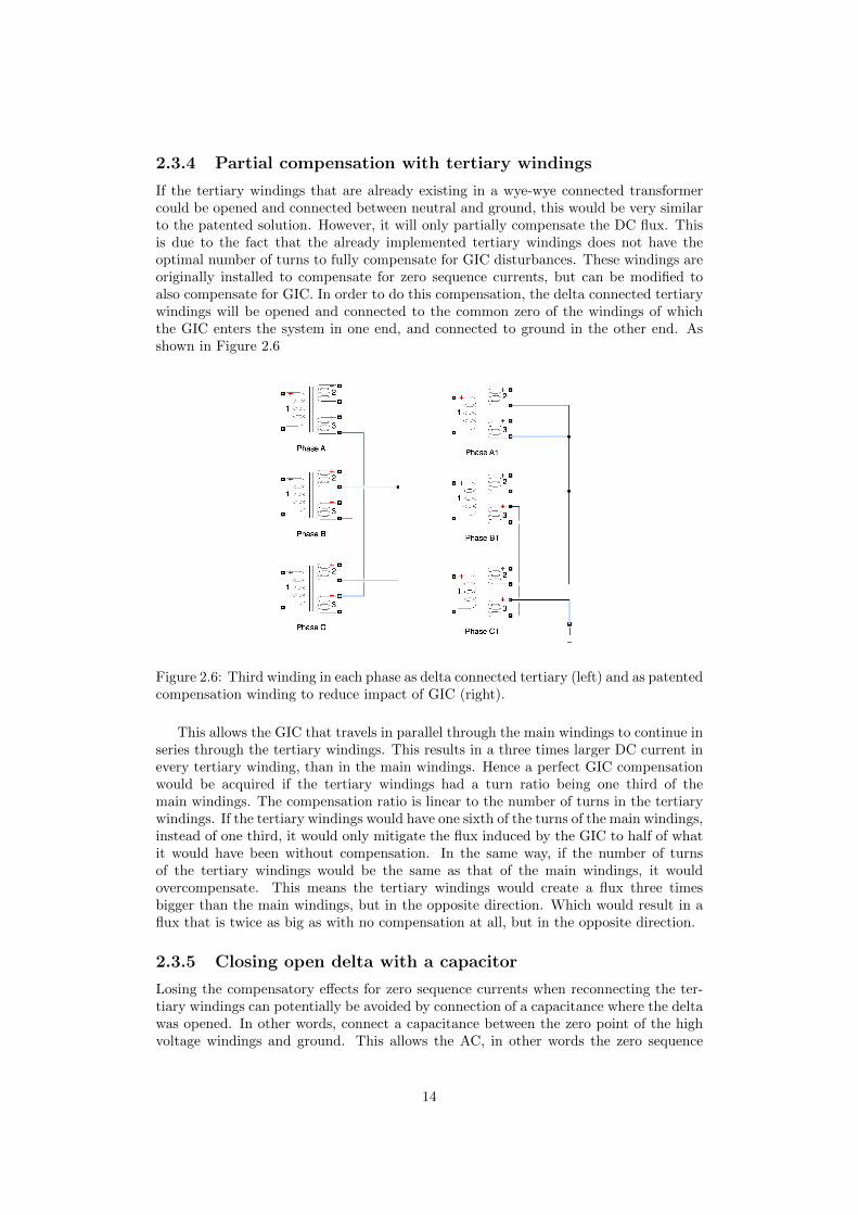
If the tertiary windings that are already existing in a wye-wye connected transformercould be opened and connected between neutral and ground, this would be very similarto the patented solution. However, it will only partially compensate the DC flux. Thisis due to the fact that the already implemented tertiary windings does not have theoptimal number of turns to fully compensate for GIC disturbances. These windings areoriginally installed to compensate for zero sequence currents, but can be modified toalso compensate for GIC. In order to do this compensation, the delta connected tertiarywindings will be opened and connected to the common zero of the windings of whichthe GIC enters the system in one end, and connected to ground in the other end. Asshown in Figure 2.6
Figure 2.6: Third winding in each phase as delta connected tertiary (left) and as patentedcompensation winding to reduce impact of GIC (right).
This allows the GIC that travels in parallel through the main windings to continue inseries through the tertiary windings. This results in a three times larger DC current inevery tertiary winding, than in the main windings. Hence a perfect GIC compensationwould be acquired if the tertiary windings had a turn ratio being one third of themain windings. The compensation ratio is linear to the number of turns in the tertiarywindings. If the tertiary windings would have one sixth of the turns of the main windings,instead of one third, it would only mitigate the flux induced by the GIC to half of whatit would have been without compensation. In the same way, if the number of turnsof the tertiary windings would be the same as that of the main windings, it wouldovercompensate. This means the tertiary windings would create a flux three timesbigger than the main windings, but in the opposite direction. Which would result in aflux that is twice as big as with no compensation at all, but in the opposite direction.
2.3.5 Closing open delta with a capacitor
Losing the compensatory effects for zero sequence currents when reconnecting the ter-tiary windings can potentially be avoided by connection of a capacitance where the deltawas opened. In other words, connect a capacitance between the zero point of the highvoltage windings and ground. This allows the AC, in other words the zero sequence
14
current to flow in the original delta winding while the DC, or GIC can flow in the newconnection in order to mitigate the DC induced flux. What could be potential prob-lem with this type of connection is that it can result in resonance, as there are bothcapacitive and inductive components.
15

Chapter 3
Equipment
This chapter will describe and motivate the equipment and power supplies that has beenused. It will also provide the transformer parameters and show the experimental circuit,Figure 3.1 where the GIC enters the system in the form of DC.
Figure 3.1: Experimental circuit used for injecting DC into transformers
3.1 Measuring equipment
All laboratory measurements were done with a Rigol DS1054 oscilloscope. To measurethe currents two Fluke AC current probes and one Kyoritsu AC/DC clamp adaptermodel 8113 were used. The voltages were measured with one Tectronix P5200A differ-ential probe and one Esselite Studium differential probe.Apart from these probes, five Biltema Art.15−124 and two MetraHit 16s multimeterswere used to measure and observe voltage and current.
16

3.2 Transformers
The single phase transformers bellow are three identical E-core transformers, seeFigure 3.2. They are specially designed with a tertiary windings that can be connectedat 42V and 73V , see Tables 3.1, 3.4. The study also uses the fact that a connection canbe put between the 42V point and 73V point, in order to get a 31V connection. Eachof the single phase transformers are rated 800VA, resulting in a 2.4kVA 3-phase systemwhen connected together.
Figure 3.2: Single phase transformers
Table 3.1: Parameters of single phase transformersPower 800VAFrequency 50 - 60HzPrimary 0 - 127 - 220VSecondary 127V / 5.2ATertiary 0 - 42 - 73V / 1.8ADimensions H x W x D 150 x 125 x 125mm
The three legged 3-phase transformer is custom made as well, with the samepossibility for the tertiary connections as the single phase transformers above, see Figure3.3 and Tables 3.2, 3.4 for transformer parameters.
17
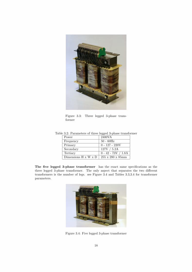
Figure 3.3: Three legged 3-phase trans-former
Table 3.2: Parameters of three legged 3-phase transformerPower 2400VAFrequency 50 - 60HzPrimary 0 - 127 - 220VSecondary 127V / 5.2ATertiary 0 - 42 - 73V / 1.8ADimensions H x W x D 255 x 280 x 85mm
The five legged 3-phase transformer has the exact same specifications as thethree legged 3-phase transformer. The only aspect that separates the two differenttransformers is the number of legs. see Figure 3.4 and Tables 3.3,3.4 for transformerparameters.
Figure 3.4: Five legged 3-phase transformer
18
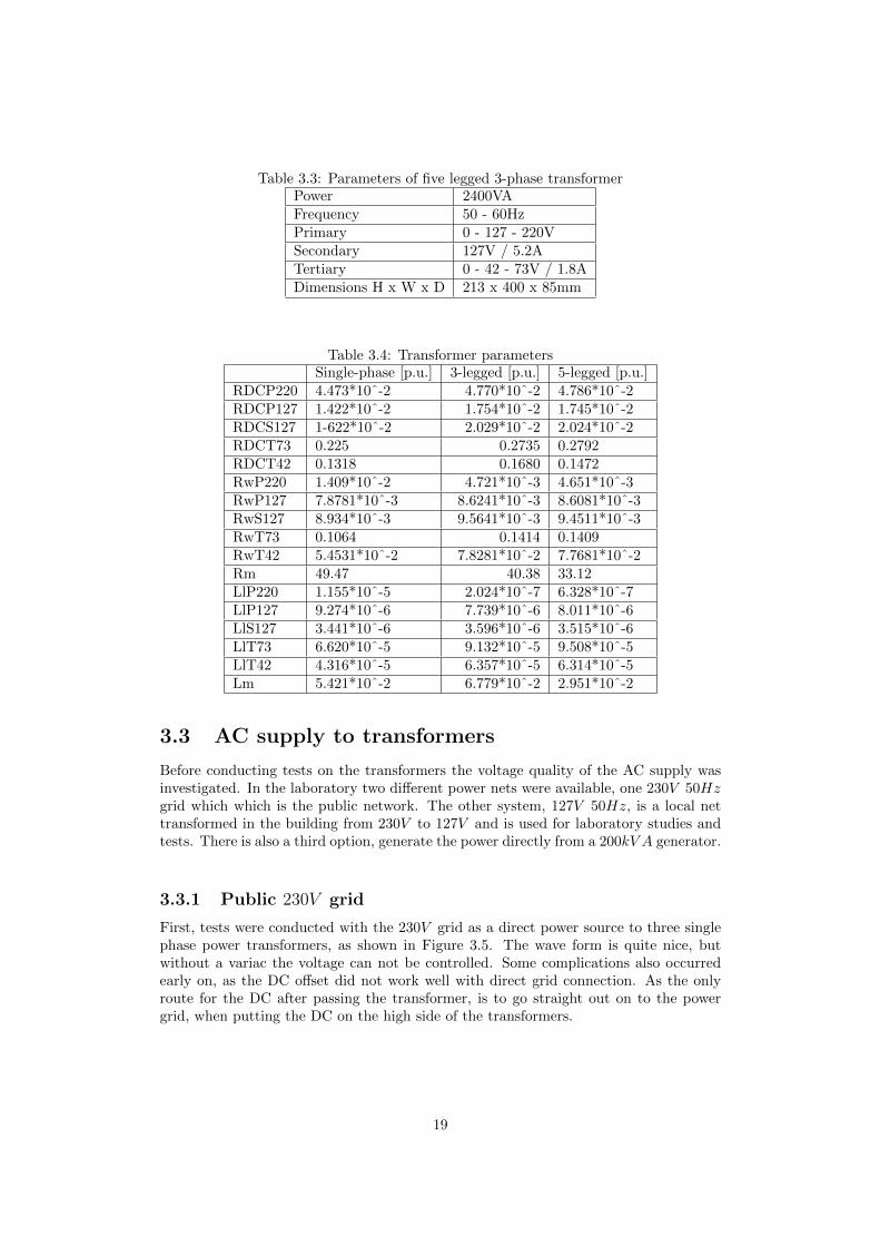
Table 3.3: Parameters of five legged 3-phase transformerPower 2400VAFrequency 50 - 60HzPrimary 0 - 127 - 220VSecondary 127V / 5.2ATertiary 0 - 42 - 73V / 1.8ADimensions H x W x D 213 x 400 x 85mm
Table 3.4: Transformer parametersSingle-phase [p.u.] 3-legged [p.u.] 5-legged [p.u.]
RDCP220 4.473*10ˆ-2 4.770*10ˆ-2 4.786*10ˆ-2RDCP127 1.422*10ˆ-2 1.754*10ˆ-2 1.745*10ˆ-2RDCS127 1-622*10ˆ-2 2.029*10ˆ-2 2.024*10ˆ-2RDCT73 0.225 0.2735 0.2792RDCT42 0.1318 0.1680 0.1472RwP220 1.409*10ˆ-2 4.721*10ˆ-3 4.651*10ˆ-3RwP127 7.8781*10ˆ-3 8.6241*10ˆ-3 8.6081*10ˆ-3RwS127 8.934*10ˆ-3 9.5641*10ˆ-3 9.4511*10ˆ-3RwT73 0.1064 0.1414 0.1409RwT42 5.4531*10ˆ-2 7.8281*10ˆ-2 7.7681*10ˆ-2Rm 49.47 40.38 33.12LlP220 1.155*10ˆ-5 2.024*10ˆ-7 6.328*10ˆ-7LlP127 9.274*10ˆ-6 7.739*10ˆ-6 8.011*10ˆ-6LlS127 3.441*10ˆ-6 3.596*10ˆ-6 3.515*10ˆ-6LlT73 6.620*10ˆ-5 9.132*10ˆ-5 9.508*10ˆ-5LlT42 4.316*10ˆ-5 6.357*10ˆ-5 6.314*10ˆ-5Lm 5.421*10ˆ-2 6.779*10ˆ-2 2.951*10ˆ-2
3.3 AC supply to transformers
Before conducting tests on the transformers the voltage quality of the AC supply wasinvestigated. In the laboratory two different power nets were available, one 230V 50Hzgrid which which is the public network. The other system, 127V 50Hz, is a local nettransformed in the building from 230V to 127V and is used for laboratory studies andtests. There is also a third option, generate the power directly from a 200kV A generator.
3.3.1 Public 230V grid
First, tests were conducted with the 230V grid as a direct power source to three singlephase power transformers, as shown in Figure 3.5. The wave form is quite nice, butwithout a variac the voltage can not be controlled. Some complications also occurredearly on, as the DC offset did not work well with direct grid connection. As the onlyroute for the DC after passing the transformer, is to go straight out on to the powergrid, when putting the DC on the high side of the transformers.
19
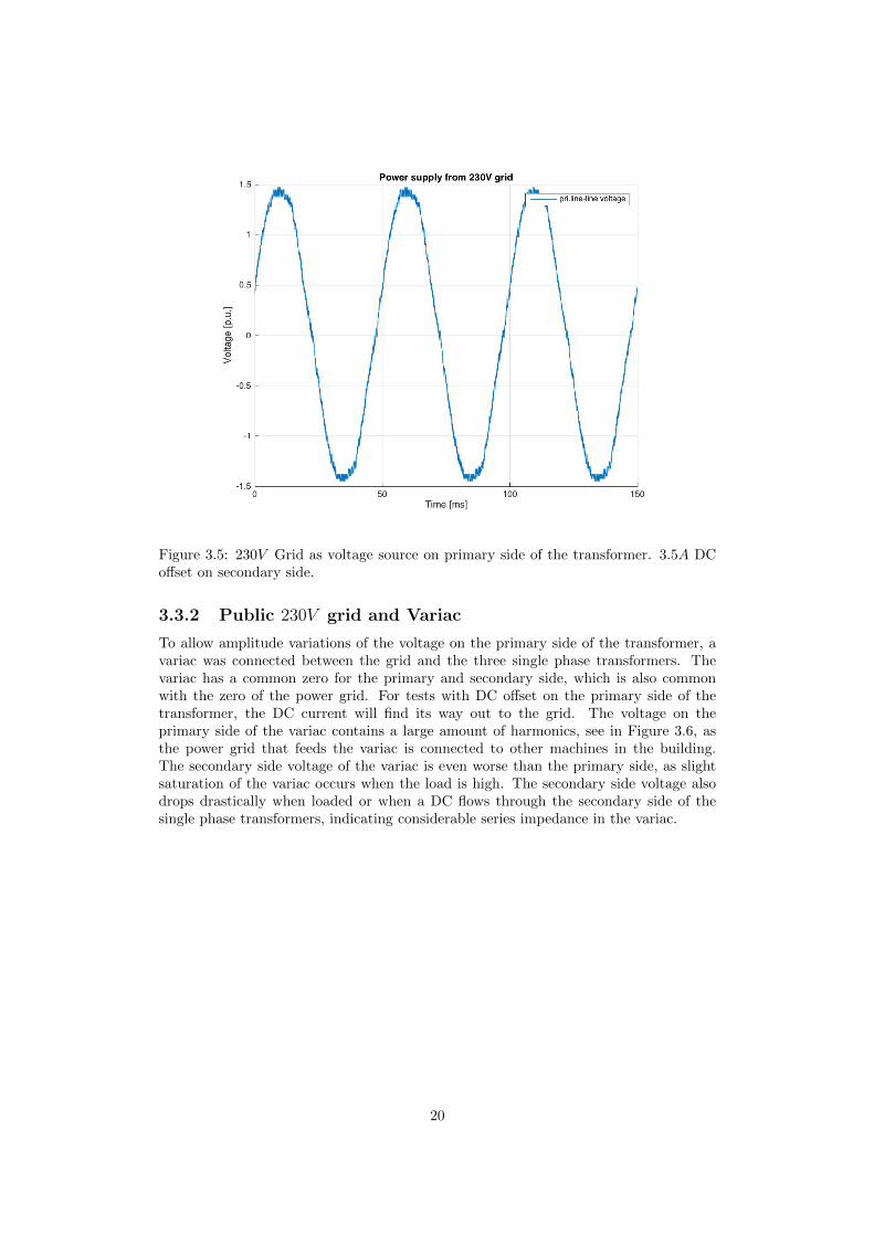
Figure 3.5: 230V Grid as voltage source on primary side of the transformer. 3.5A DCoffset on secondary side.
3.3.2 Public 230V grid and Variac
To allow amplitude variations of the voltage on the primary side of the transformer, avariac was connected between the grid and the three single phase transformers. Thevariac has a common zero for the primary and secondary side, which is also commonwith the zero of the power grid. For tests with DC offset on the primary side of thetransformer, the DC current will find its way out to the grid. The voltage on theprimary side of the variac contains a large amount of harmonics, see in Figure 3.6, asthe power grid that feeds the variac is connected to other machines in the building.The secondary side voltage of the variac is even worse than the primary side, as slightsaturation of the variac occurs when the load is high. The secondary side voltage alsodrops drastically when loaded or when a DC flows through the secondary side of thesingle phase transformers, indicating considerable series impedance in the variac.
20

Figure 3.6: Variac as voltage source on primary side of the transformer. 3.5A DC offseton secondary side.
3.3.3 From 127V grid to variac to step up transformer
A poor primary voltage may cause harmonics in the final result, therefore it is veryimportant to use a power source which is as ideal as possible. In order to find a good pri-mary voltage the 127V grid of was connected to the variac, which in turn was connectedto a step up transformer, which is connected to the three single phase transformers.This improved the secondary side voltage of the variac as the supply grid had a smothersinusoidal form, as well as the variac did not get saturated. However, the voltage of thesecondary side of the step up transformer had a poor waveform, see Figure 3.7, there-fore it may contaminate the final results. However, this way of feeding the transformeralso allow us to drive big DC current on the primary side of the transformer, as it isgalvanically isolated from the net through the step up transformer.
21

Figure 3.7: 127 grid to variac to step up transformer as voltage source on primary sideof the transformer. 3.5A GIC on secondary side.
3.3.4 200kV A synchronous generator
To conduct more precise measurements with a true sinusoidal voltage instead of thecontaminated voltage in the power grid, see Figure 3.5, 3.6, 3.7. The test system issupplied from a 200kV A synchronous generator powered by a 50kW DC motor. Thissupply proved to have a very clean sinusoidal voltage and no obvious inductance prob-lems, see Figure 3.8. It also allowed us to do tests with DC offset on the primary sideof the transformer, as a small DC offset was no problem for the generator. Therefor, itwas decided to conduct all following measurements using this synchronous generator.
22
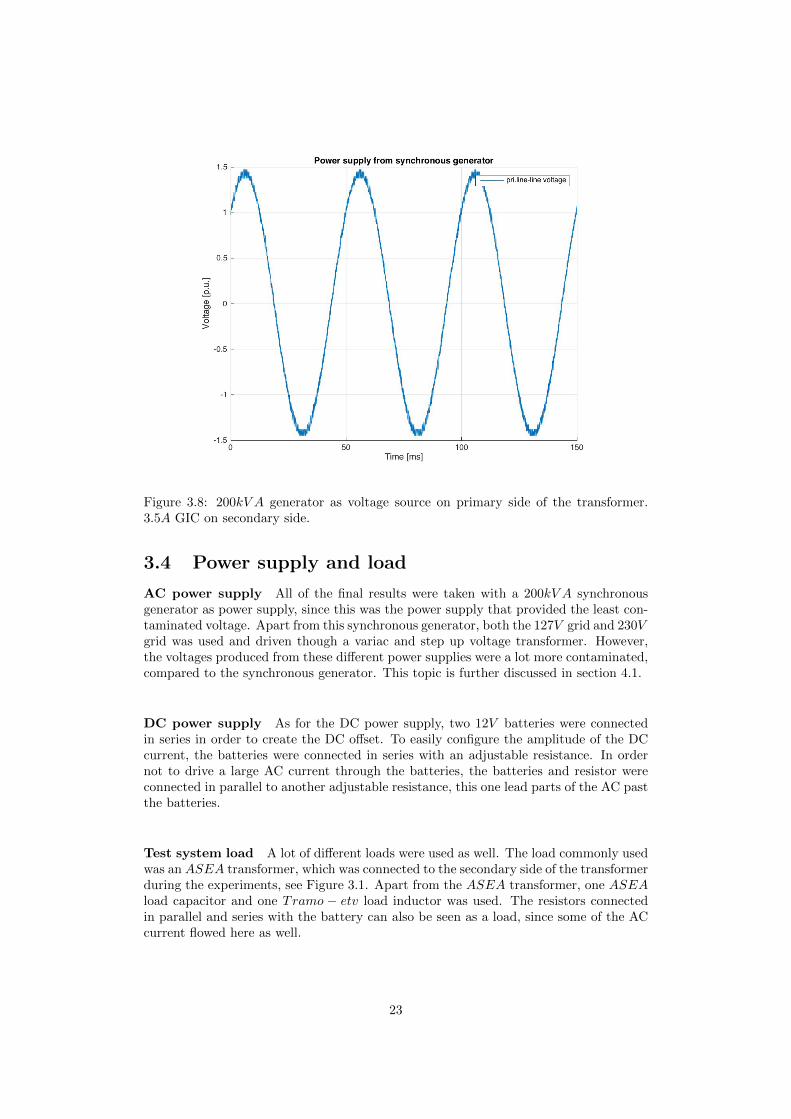
Figure 3.8: 200kV A generator as voltage source on primary side of the transformer.3.5A GIC on secondary side.
3.4 Power supply and load
AC power supply All of the final results were taken with a 200kV A synchronousgenerator as power supply, since this was the power supply that provided the least con-taminated voltage. Apart from this synchronous generator, both the 127V grid and 230Vgrid was used and driven though a variac and step up voltage transformer. However,the voltages produced from these different power supplies were a lot more contaminated,compared to the synchronous generator. This topic is further discussed in section 4.1.
DC power supply As for the DC power supply, two 12V batteries were connectedin series in order to create the DC offset. To easily configure the amplitude of the DCcurrent, the batteries were connected in series with an adjustable resistance. In ordernot to drive a large AC current through the batteries, the batteries and resistor wereconnected in parallel to another adjustable resistance, this one lead parts of the AC pastthe batteries.
Test system load A lot of different loads were used as well. The load commonly usedwas an ASEA transformer, which was connected to the secondary side of the transformerduring the experiments, see Figure 3.1. Apart from the ASEA transformer, one ASEAload capacitor and one Tramo − etv load inductor was used. The resistors connectedin parallel and series with the battery can also be seen as a load, since some of the ACcurrent flowed here as well.
23
Chapter 4
Experiments - steady state
4.1 Hysteresis curve for transformers
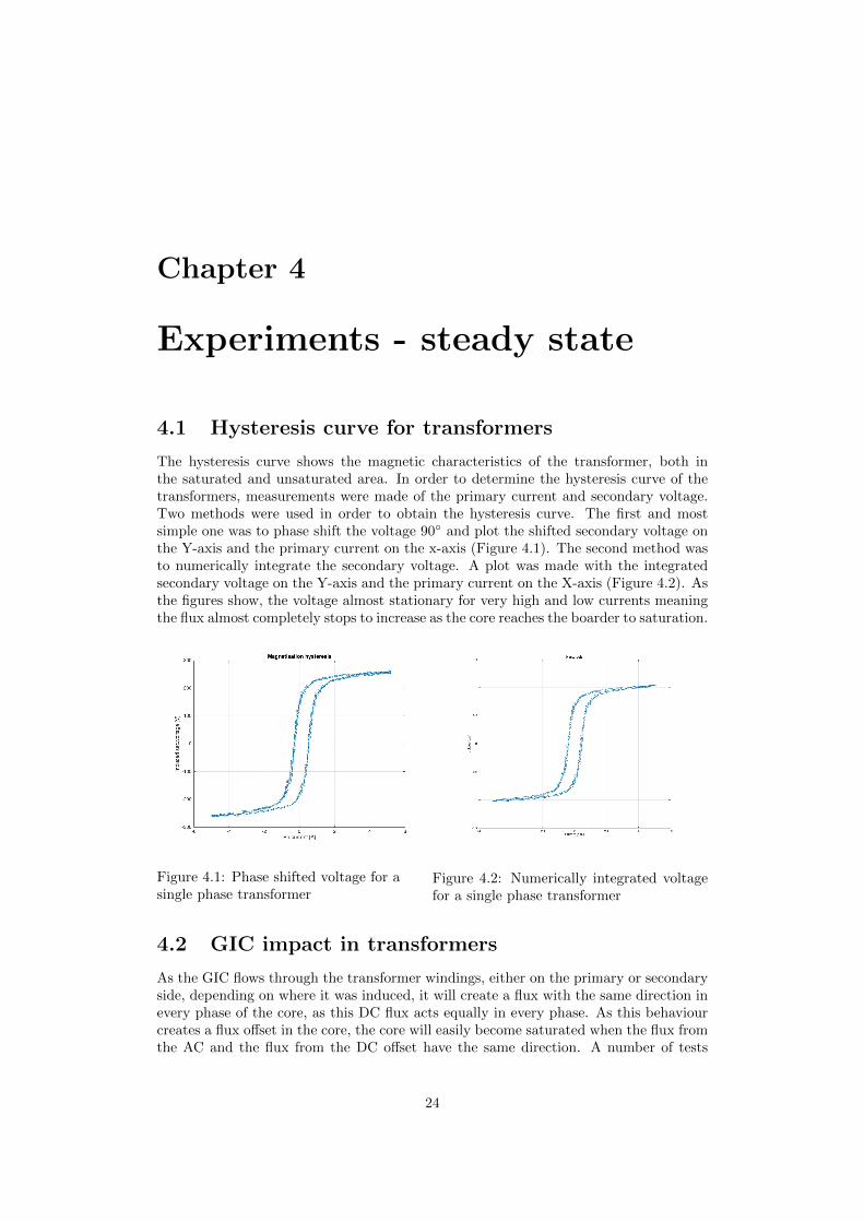
The hysteresis curve shows the magnetic characteristics of the transformer, both inthe saturated and unsaturated area. In order to determine the hysteresis curve of thetransformers, measurements were made of the primary current and secondary voltage.Two methods were used in order to obtain the hysteresis curve. The first and mostsimple one was to phase shift the voltage 90◦ and plot the shifted secondary voltage onthe Y-axis and the primary current on the x-axis (Figure 4.1). The second method wasto numerically integrate the secondary voltage. A plot was made with the integratedsecondary voltage on the Y-axis and the primary current on the X-axis (Figure 4.2). Asthe figures show, the voltage almost stationary for very high and low currents meaningthe flux almost completely stops to increase as the core reaches the boarder to saturation.
Figure 4.1: Phase shifted voltage for asingle phase transformer
Figure 4.2: Numerically integrated voltagefor a single phase transformer
4.2 GIC impact in transformers
As the GIC flows through the transformer windings, either on the primary or secondaryside, depending on where it was induced, it will create a flux with the same direction inevery phase of the core, as this DC flux acts equally in every phase. As this behaviourcreates a flux offset in the core, the core will easily become saturated when the flux fromthe AC and the flux from the DC offset have the same direction. A number of tests
24

were performed on each transformer in this section in order to compare the transformersbehaviour with and without a DC offset.
4.2.1 Single phase transformers
The single phase transformers were tested with and without GIC, see Figure 3.1 withoutany compensation windings, in order to see the impact the GIC has on the transformerswithout any attempts of mitigation.
Figure 4.3: Primary and tertiary currentwithout GIC and compensation
Figure 4.4: Primary and tertiary currentwith 3.5A GIC, without compensation.
Comparing Figures 4.3 and 4.4 shows that, the GIC has a considerable impact onthe primary current, as the DC offset partially saturates the core and the AC waveformgets distorted. In Figure 4.4 a third harmonic is visible in the tertiary winding current.This third harmonic is a result of the saturation of the transformer cores. When atransformer is driven into saturation the AC waveform becomes distorted and containsboth even and odd harmonics, [11]. This second harmonic is present in the primarycurrent, but is really hard to distinguish in the waveform. Therefore, a Fast FourierTransform (FFT) was performed to determine the spectral content of the waveform.This clearly shows the presence of the 2nd harmonic (100Hz), (Figure 4.5). Note thatdeep saturation does not give rise to a third harmonic, but rather to a sixth harmonicin the tertiary winding, this is slightly visible in Figure 4.5.
25
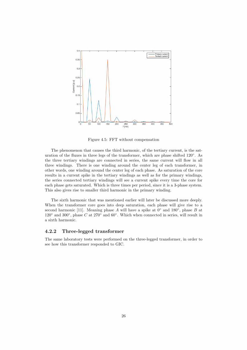
Figure 4.5: FFT without compensation
The phenomenon that causes the third harmonic, of the tertiary current, is the sat-uration of the fluxes in three legs of the transformer, which are phase shifted 120◦. Asthe three tertiary windings are connected in series, the same current will flow in allthree windings. There is one winding around the center leg of each transformer, inother words, one winding around the center leg of each phase. As saturation of the coreresults in a current spike in the tertiary windings as well as for the primary windings,the series connected tertiary windings will see a current spike every time the core foreach phase gets saturated. Which is three times per period, since it is a 3-phase system.This also gives rise to smaller third harmonic in the primary winding.
The sixth harmonic that was mentioned earlier will later be discussed more deeply.When the transformer core goes into deep saturation, each phase will give rise to asecond harmonic [11]. Meaning phase A will have a spike at 0◦ and 180◦, phase B at120◦ and 300◦, phase C at 270◦ and 60◦. Which when connected in series, will result ina sixth harmonic.
4.2.2 Three-legged transformer
The same laboratory tests were performed on the three-legged transformer, in order tosee how this transformer responded to GIC.
26

Figure 4.6: Primary and tertiarycurrent without GIC and compensation
Figure 4.7: Primary and tertiary currentwith 3.5A GIC, without compensation.
Comparison of Figures 4.6 and 4.7 shows that the three-legged transformer is hardlyaffected by GIC. This is a great contrast to the single phase transformers, 4.3 and 4.4.
4.2.3 Five-legged transformer
Finally, the tests were performed on the five legged transformer, see Figure 4.8 andFigure 4.9. The GIC had a huge impact on this transformer, as the outer legs of thetransformer provide a low reluctance path for the flux created by the GIC. There is alsoa very visible third harmonic in the primary current, both with and without GIC.
Figure 4.8: Primary and tertiary currentwithout GIC and compensation
Figure 4.9: Primary and tertiary currentwith 3.5A GIC, without compensation.
4.2.4 Harmonics in transformers without GIC
As Figures 4.6 and 4.8 show, the primary current is not only a 50 Hz fundamental. Whendoing a FFT on these currents, Figures 4.10 and 4.11 show that there is a third, fifth andseventh harmonic in the case without GIC. As there is no load on the transformers andno faults or disturbances during the tests, these harmonics are assumed to be a resultof transformer design not being fully symmetric as desired. The results of the singlephase transformers are a lot better, see Figures 4.3, 4.6 and 4.8. Due to this fact, theexperiments, and thus also the simulations, will focus on the single phase transformers.
27

This is also the transformer type used in the simulations made by Boteler and Bradley[8] which allows comparison with their results.
Figure 4.10: FFT, Three legged transformer Figure 4.11: FFT, Five legged transformer
4.3 GIC mitigation in transformers
This part will compare the GIC mitigation that will be produced by different numberof turns on the compensation windings.
The GIC is running through the secondary windings in parallel. The normally deltaconnected tertiary windings are opened and one end is connected to the neutral pointof the secondary winding and the other end to ground, changing the purpose of thesetertiary windings from zero sequence current compensation to GIC compensation, seethis reconfiguration in Figure 4.12 This results in three times as large DC in every com-pensation winding compared to every secondary winding. Hence, tertiary windings withone third of the voltage of the secondary windings will lead to perfect flux compensationof the GIC. This is assuming that the GIC is led through the tertiary winding in theopposite direction of the secondary winding. If the tertiary winding has less than athird of the voltage of the winding which the GIC is led through, the GIC will only bereduced and not completely eliminated. If the tertiary winding has more than a third ofthe voltage of the winding which the GIC is led through, it will overcompensate. Thisleads to a saturation at the opposite side.
In this section under-compensation, perfect-compensation and over-compensationwill be studied on the three different transformer types.
28

Figure 4.12: Reconnection from delta to compensation winding
4.3.1 Single phase transformers with compensation winding
To achieve perfect compensation the compensation winding would have to have onethird of the voltage of the winding that is exposed to the GIC.
3 ∗ 42V
127V=
126V
127V≈ 1
This was examined in the lab, and the result was just as expected, perfect compensation,see Figure 4.13.
29
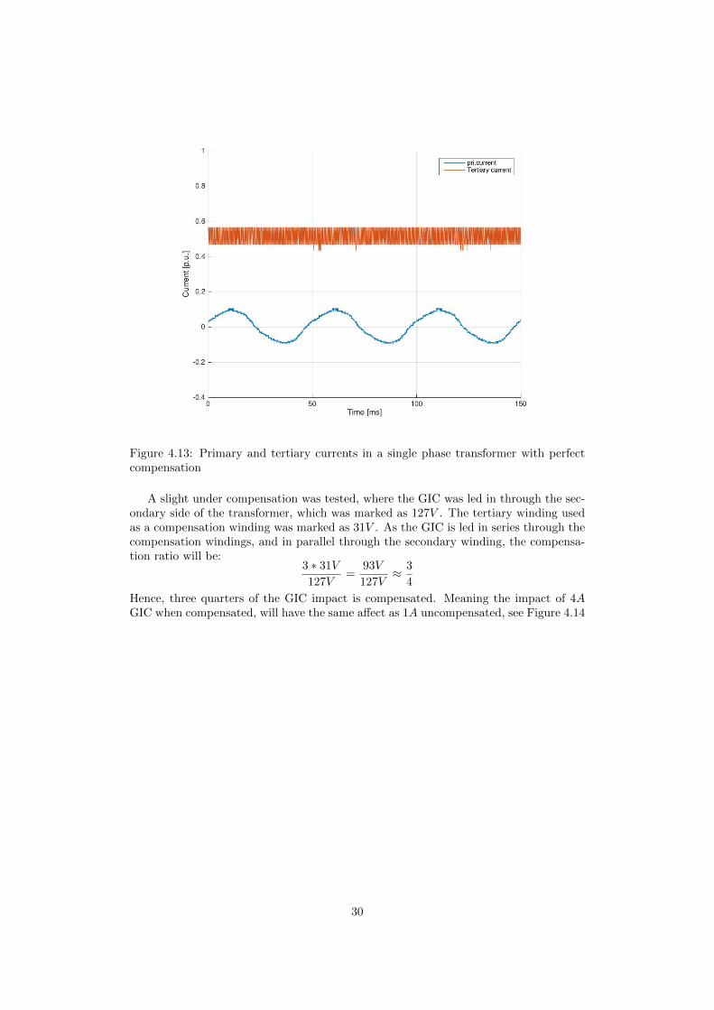
Figure 4.13: Primary and tertiary currents in a single phase transformer with perfectcompensation
A slight under compensation was tested, where the GIC was led in through the sec-ondary side of the transformer, which was marked as 127V . The tertiary winding usedas a compensation winding was marked as 31V . As the GIC is led in series through thecompensation windings, and in parallel through the secondary winding, the compensa-tion ratio will be:
3 ∗ 31V
127V=
93V
127V≈ 3
4
Hence, three quarters of the GIC impact is compensated. Meaning the impact of 4AGIC when compensated, will have the same affect as 1A uncompensated, see Figure 4.14
30

Figure 4.14: Primary and tertiary currents in a single phase transformer with threefourths mitigation
Finally a test was conducted with over compensation. The DC offset was led throughthe secondary 127 volt winding as before, but instead of using a 31V compensationwinding, a 73V compensation winding was used. This results in a compensation of
3 ∗ 73V
127V=
219V
127V≈ 7
4
This over compensation is very visible on the primary current, as it now peaks onthe negative side, instead of the positive, see Figure 4.15.
31
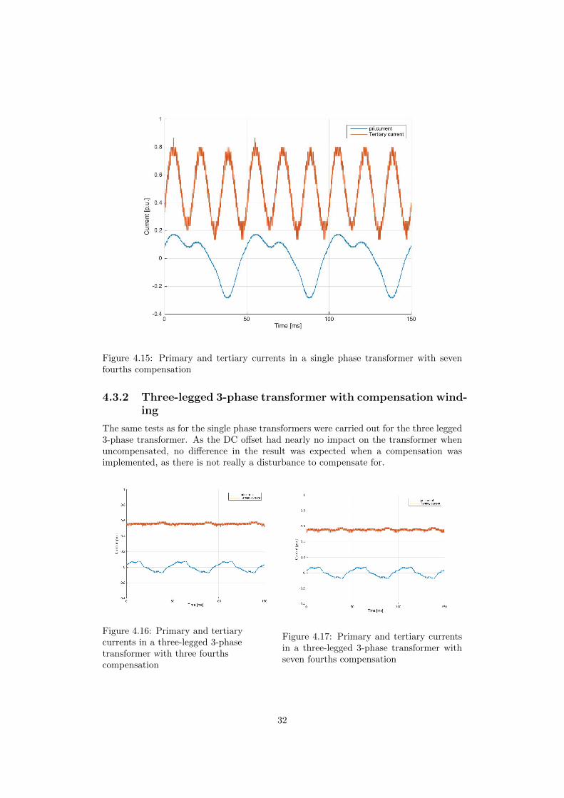
Figure 4.15: Primary and tertiary currents in a single phase transformer with sevenfourths compensation
4.3.2 Three-legged 3-phase transformer with compensation wind-ing
The same tests as for the single phase transformers were carried out for the three legged3-phase transformer. As the DC offset had nearly no impact on the transformer whenuncompensated, no difference in the result was expected when a compensation wasimplemented, as there is not really a disturbance to compensate for.
Figure 4.16: Primary and tertiarycurrents in a three-legged 3-phasetransformer with three fourthscompensation
Figure 4.17: Primary and tertiary currentsin a three-legged 3-phase transformer withseven fourths compensation
32
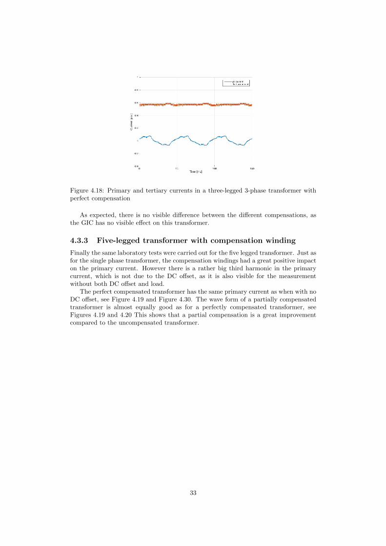
Figure 4.18: Primary and tertiary currents in a three-legged 3-phase transformer withperfect compensation
As expected, there is no visible difference between the different compensations, asthe GIC has no visible effect on this transformer.
4.3.3 Five-legged transformer with compensation winding
Finally the same laboratory tests were carried out for the five legged transformer. Just asfor the single phase transformer, the compensation windings had a great positive impacton the primary current. However there is a rather big third harmonic in the primarycurrent, which is not due to the DC offset, as it is also visible for the measurementwithout both DC offset and load.
The perfect compensated transformer has the same primary current as when with noDC offset, see Figure 4.19 and Figure 4.30. The wave form of a partially compensatedtransformer is almost equally good as for a perfectly compensated transformer, seeFigures 4.19 and 4.20 This shows that a partial compensation is a great improvementcompared to the uncompensated transformer.
33

Figure 4.19: Primary and tertiary currents in a five-legged 3-phase transformer withperfect compensation
Figure 4.20: Primary and tertiary currents in a five-legged 3-phase transformer withthree fourths compensation
As Figure 4.20 shows, this is a great improvement from the uncompensated trans-
34

former. However, the third harmonic is still very visible.The final Figure 4.21 concerning mitigation of GIC, the over compensation was executedon the five legged transformer. The result was as expected, negative current spikes onthe primary current and a very visible third harmonic.
Figure 4.21: Primary and tertiary currents in a five-legged 3-phase transformer withseven fourths compensation
4.4 Comparison
In order to more easily compare of the mitigating effect that different number of turns onthe compensation winding provides, plots with the same GIC and different configurationsof compensation windings are compared more closely in this section. We chose not tocompare with the plots where the compensation winding was overcompensating, as thisis not likely to happen in reality.
4.4.1 Single phase transformer
There is a very visible third harmonic in the tertiary current, which is most likely aresult of the core saturation that occurs once every cycle for each phase. As visiblein the Figures 4.22, 4.23, 4.24, 4.25, the amplitude of the harmonic decreases as theGIC induced flux is compensated and no saturation occurs, leaving no third harmonicwhen the GIC is perfectly compensated. As seen in Figure 4.5 there is a clear secondharmonic in the primary windings, apart from the obvious fundamental frequency. Thisis a result of deep saturation, which also can be seen from the slight sixth harmonic inthe compensation windings.
35

Figure 4.22: Primary and tertiarycurrents in a single phase transformerwithout GIC and compensation
Figure 4.23: Primary and tertiary currentsin a single phase transformer with 3.5A GIC,without compensation
Figure 4.24: Primary and tertiarycurrents in a single phase transformerwith 3.5A GIC and three fourthsmitigation
Figure 4.25: Primary and tertiary currentsin a single phase transformer with 3.5A GICand perfect mitigation
4.4.2 Three legged 3-phase transformer
The three legged 3-phase transformer shows no visible change of the primary currentswhen the GIC is applied in the tertiary windings, see Figures 4.26, 4.27, 4.28, 4.29.This is due to the fact that it is very hard for a DC offset to drive a three legged3-phase transformer into saturation, as there is no available leg for the extra flux toreturn through. This design makes the three legged transformer superior to the othertransformers, when it comes to handling GIC. However the primary current in the plotsis not a nice sinusoidal current. This has nothing to do with the fact that we were usinga three legged 3-phase transformer. But rather that the transformer is designed in away that it slightly saturates when operating at nominal voltage.
36

Figure 4.26: Primary and tertiarycurrents in a three legged 3-phasetransformer without GIC andcompensation
Figure 4.27: Primary and tertiary currentsin a three legged 3-phase transformer, with3.5A GIC and without compensation
Figure 4.28: Primary and tertiarycurrents in a three legged 3-phasetransformer, with 3.5A GIC andthree fourths mitigation
Figure 4.29: Primary and tertiary currentsin a three legged 3-phase transformer, with3.5A GIC and perfect mitigation
4.4.3 Five legged 3-phase transformer
Finally, the five legged transformer showed the same problem with the primary currentat nominal voltage and no DC offset as the three legged did. However, the differencebetween these two transformers is that the five legged transformer handles the DC offseta lot worse than the three legged, as there are two outer legs where the flux inducedby the GIC can return. Compared to the three single phase transformer, the negativeeffects of the GIC are similar, as there are paths for the DC induced flux to return inboth cases. But as the Figures 4.22, 4.23, 4.24, 4.25 compared to 4.30, 4.31, 4.32, 4.33shows, the single phase transformer had a lot less trouble with harmonics, this is mostlikely due to the fact that the single phase transformer are better designed than the fivelegged transformer. As in the case where a five legged transformer is well designed, itdoes not go into saturation at nominal voltage and no load.
37
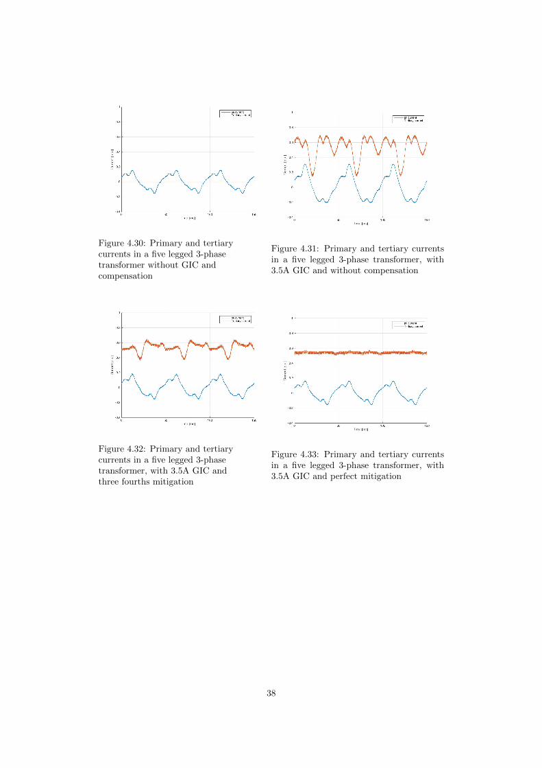
Figure 4.30: Primary and tertiarycurrents in a five legged 3-phasetransformer without GIC andcompensation
Figure 4.31: Primary and tertiary currentsin a five legged 3-phase transformer, with3.5A GIC and without compensation
Figure 4.32: Primary and tertiarycurrents in a five legged 3-phasetransformer, with 3.5A GIC andthree fourths mitigation
Figure 4.33: Primary and tertiary currentsin a five legged 3-phase transformer, with3.5A GIC and perfect mitigation
38
Chapter 5
Experiments - transients
5.1 GIC step response
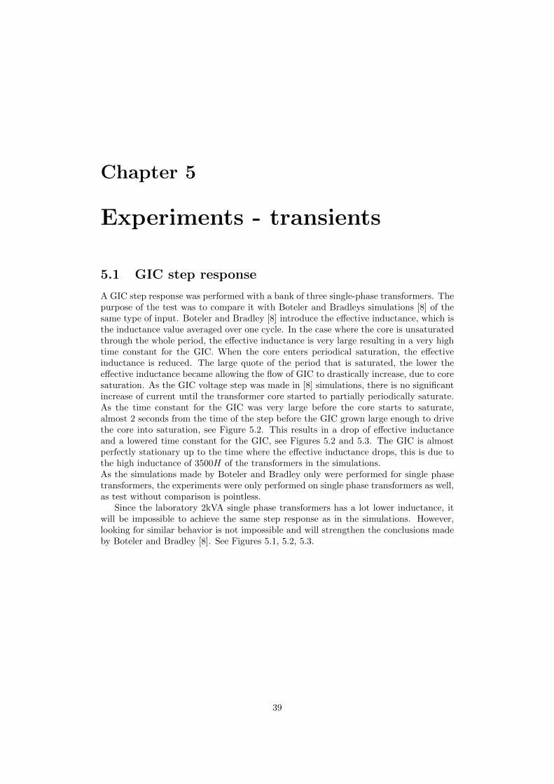
A GIC step response was performed with a bank of three single-phase transformers. Thepurpose of the test was to compare it with Boteler and Bradleys simulations [8] of thesame type of input. Boteler and Bradley [8] introduce the effective inductance, which isthe inductance value averaged over one cycle. In the case where the core is unsaturatedthrough the whole period, the effective inductance is very large resulting in a very hightime constant for the GIC. When the core enters periodical saturation, the effectiveinductance is reduced. The large quote of the period that is saturated, the lower theeffective inductance became allowing the flow of GIC to drastically increase, due to coresaturation. As the GIC voltage step was made in [8] simulations, there is no significantincrease of current until the transformer core started to partially periodically saturate.As the time constant for the GIC was very large before the core starts to saturate,almost 2 seconds from the time of the step before the GIC grown large enough to drivethe core into saturation, see Figure 5.2. This results in a drop of effective inductanceand a lowered time constant for the GIC, see Figures 5.2 and 5.3. The GIC is almostperfectly stationary up to the time where the effective inductance drops, this is due tothe high inductance of 3500H of the transformers in the simulations.As the simulations made by Boteler and Bradley only were performed for single phasetransformers, the experiments were only performed on single phase transformers as well,as test without comparison is pointless.
Since the laboratory 2kVA single phase transformers has a lot lower inductance, itwill be impossible to achieve the same step response as in the simulations. However,looking for similar behavior is not impossible and will strengthen the conclusions madeby Boteler and Bradley [8]. See Figures 5.1, 5.2, 5.3.
39

Figure 5.1: Voltage step Figure 5.2: Inductance drop
Figure 5.3: DC step
5.1.1 Without GIC mitigation windings
Experiments were first performed without any type of GIC mitigation windings, whichis the same set up as in the simulations in [8]. The experiments were performed with50V ,100V ,150V and 200V AC phase to ground voltage, where it is expected that higherAC voltage will earlier saturate the core. This resulted in a lower effective inductancefor higher AC voltages. The DC offset is visible in Figure 5.4.
Figure 5.4: Step response
40
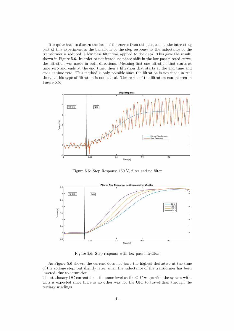
It is quite hard to discern the form of the curves from this plot, and as the interestingpart of this experiment is the behaviour of the step response as the inductance of thetransformer is reduced, a low pass filter was applied to the data. This gave the result,shown in Figure 5.6. In order to not introduce phase shift in the low pass filtered curve,the filtration was made in both directions. Meaning first one filtration that starts attime zero and ends at the end time, then a filtration that starts at the end time andends at time zero. This method is only possible since the filtration is not made in realtime, as this type of filtration is non causal. The result of the filtration can be seen inFigure 5.5.
Figure 5.5: Step Response 150 V, filter and no filter
Figure 5.6: Step response with low pass filtration
As Figure 5.6 shows, the current does not have the highest derivative at the timeof the voltage step, but slightly later, when the inductance of the transformer has beenlowered, due to saturation.The stationary DC current is on the same level as the GIC we provide the system with.This is expected since there is no other way for the GIC to travel than through thetertiary windings.
41
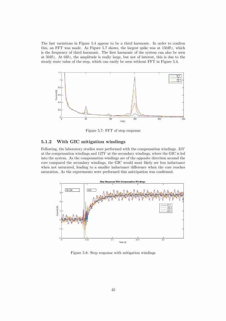
The fast variations in Figure 5.4 appear to be a third harmonic. In order to confirmthis, an FFT was made. As Figure 5.7 shows, the largest spike was at 150Hz, whichis the frequency of third harmonic. The first harmonic of the system can also be seenat 50Hz. At 0Hz, the amplitude is really large, but not of interest, this is due to thesteady state value of the step, which can easily be seen without FFT in Figure 5.4.
Figure 5.7: FFT of step response
5.1.2 With GIC mitigation windings
Following, the laboratory studies were performed with the compensation windings. 31Vat the compensation windings and 127V at the secondary windings, where the GIC is ledinto the system. As the compensation windings are of the opposite direction around thecore compared the secondary windings, the GIC would most likely see less inductancewhen not saturated, leading to a smaller inductance difference when the core reachessaturation. As the experiments were performed this anticipation was confirmed.
Figure 5.8: Step response with mitigation windings
42
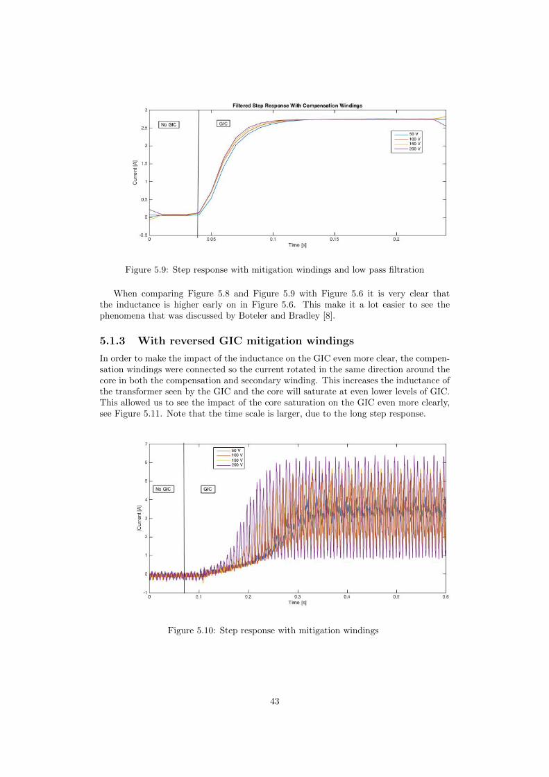
Figure 5.9: Step response with mitigation windings and low pass filtration
When comparing Figure 5.8 and Figure 5.9 with Figure 5.6 it is very clear thatthe inductance is higher early on in Figure 5.6. This make it a lot easier to see thephenomena that was discussed by Boteler and Bradley [8].
5.1.3 With reversed GIC mitigation windings
In order to make the impact of the inductance on the GIC even more clear, the compen-sation windings were connected so the current rotated in the same direction around thecore in both the compensation and secondary winding. This increases the inductance ofthe transformer seen by the GIC and the core will saturate at even lower levels of GIC.This allowed us to see the impact of the core saturation on the GIC even more clearly,see Figure 5.11. Note that the time scale is larger, due to the long step response.
Figure 5.10: Step response with mitigation windings
43

Figure 5.11: Step response with mitigation windings and low pass filtration
5.1.4 Summary
As seen in section 4.6, the larger inductance, seen from the GIC point of view, the longerit takes before the GIC reaches its steady state value. However, when the inductance islarger, the amplitude of the magnetic flux will also be larger. As discussed earlier in thischapter, the time constant for the step increases in proportion with the inductance seenfrom the GIC, as well as the magnetic flux which also increases proportionally to theinductance. This results in that the rate of the saturation will increase equally fast nomatter what inductance that is seen from the GIC. However, it will increase for a longerperiod of time with a large inductance, resulting in the core reaching deeper saturationfor higher inductance.As there is a lot of third harmonic, it is a bit hard to see what is actually happening andall trust has to be put on the filtered signal. In order to see what really is happeningwithout using a filter, the same test will be performed again, but with only one phaseconnected. This is not commonly used in reality, but was used by Boteler and Bradley[8] and will help get a better look into the current step of the single phase transformer.
5.2 One phase GIC step response
In order to remove the disturbance of the third harmonic when investigating the stepresponse, two phases were disconnected and the experiments of section 4.5 where exe-cuted for only one phase instead of three phases. This laboratory study will mostly becomparable with the simulations in [8], as they only used one phase in their simulations.However, the experiments of section 6.4 is more applicable on a real case scenario, asthe majority of power transformers are working with three phases.
5.2.1 Without GIC mitigation winding
Just as anticipated, there was no third harmonic. However, the measurements still hadto be filtered, as the fundamental was large at the point of saturation. Which makes ithard to distinguish the DC current step.
44

Figure 5.12: Step response without mitigation windings, one phase only
When filtered, the same behaviour of the time constant accrues as in section 4.6,which was anticipated. However, there is no difference in the amplitude of the rate ofchange in the GIC when different AC voltages is applied on the primary side. The reasonwhy there is no difference in the rate of current change, as a function of the primary ACvoltage, has further been studied in section 4.8.
Figure 5.13: Step response without mitigation windings and low pass filtration, onephase only
5.2.2 With GIC mitigation winding
When the compensation windings are implemented the inductance seen from the GICwas anticipated to be lowered, resulting in a shorter time constant for the current stepresponse of the GIC. However, the time constant was not visibly lowered in this casewhere only one phase was connected. When comparing Figure 5.11 with Figure 5.9, itis very clear to see that the compensation windings has a larger impact in reducing the
45
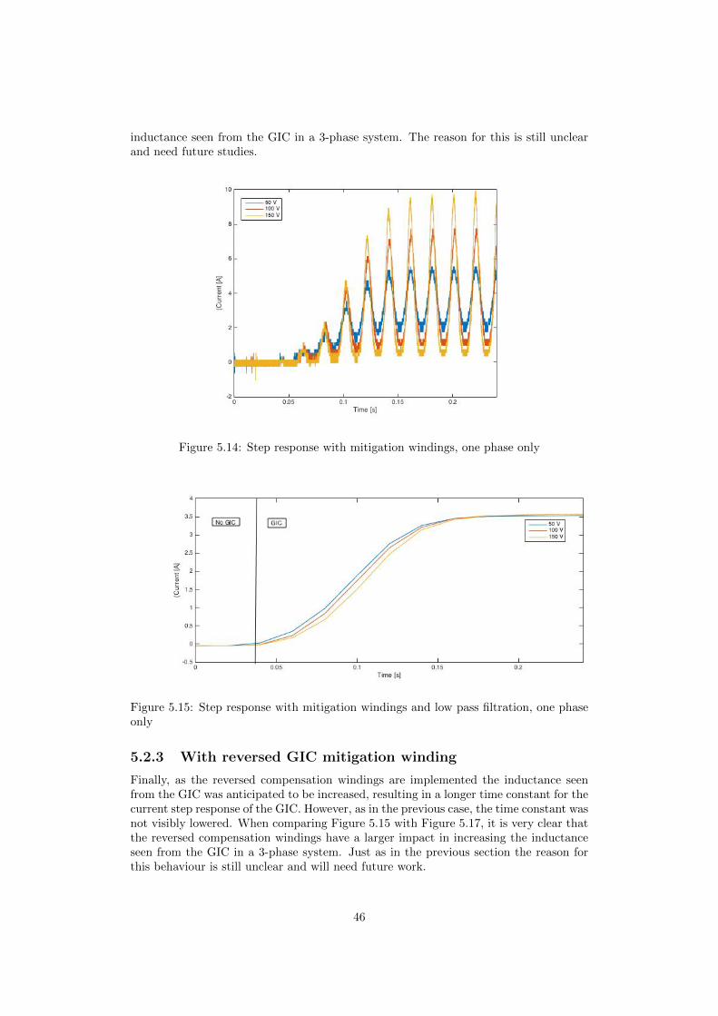
inductance seen from the GIC in a 3-phase system. The reason for this is still unclearand need future studies.
Figure 5.14: Step response with mitigation windings, one phase only
Figure 5.15: Step response with mitigation windings and low pass filtration, one phaseonly
5.2.3 With reversed GIC mitigation winding
Finally, as the reversed compensation windings are implemented the inductance seenfrom the GIC was anticipated to be increased, resulting in a longer time constant for thecurrent step response of the GIC. However, as in the previous case, the time constant wasnot visibly lowered. When comparing Figure 5.15 with Figure 5.17, it is very clear thatthe reversed compensation windings have a larger impact in increasing the inductanceseen from the GIC in a 3-phase system. Just as in the previous section the reason forthis behaviour is still unclear and will need future work.
46
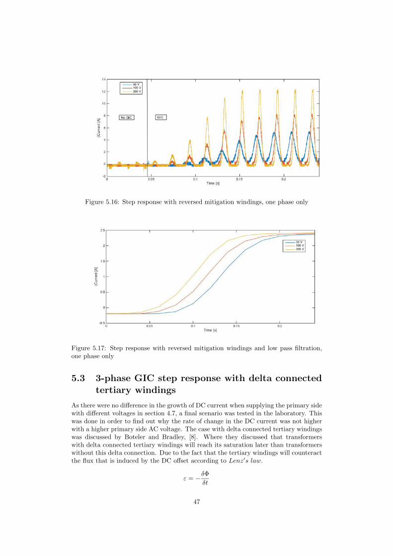
Figure 5.16: Step response with reversed mitigation windings, one phase only
Figure 5.17: Step response with reversed mitigation windings and low pass filtration,one phase only
5.3 3-phase GIC step response with delta connectedtertiary windings
As there were no difference in the growth of DC current when supplying the primary sidewith different voltages in section 4.7, a final scenario was tested in the laboratory. Thiswas done in order to find out why the rate of change in the DC current was not higherwith a higher primary side AC voltage. The case with delta connected tertiary windingswas discussed by Boteler and Bradley, [8]. Where they discussed that transformerswith delta connected tertiary windings will reach its saturation later than transformerswithout this delta connection. Due to the fact that the tertiary windings will counteractthe flux that is induced by the DC offset according to Lenz′s law.
ε = −δΦδt
47

Another nice aspect of the tertiary windings, when delta connected, is that it compen-sates for the third harmonic. Low pass filtration of the GIC should therefore not benecessary.
5.3.1 No delta windings
In order to really understand what happened with the current step response when thetertiary windings are delta connected, there was first some measurements taken withoutthe tertiary windings. The actual measurements of the experiments can be seen inFigure 5.18 and the low pass filtered measurements seen in 5.19. Just as in section 4.6,it is very clear to see that the growth of the DC offset is larger when the input voltageon the primary side of the transformer is larger. This is, as explained in 4.6, due tothe fact that the effective inductance is lower when the input voltage is higher, as thetime of saturation is longer with a higher input AC voltage at the primary side. Thelarger rate of change is due to a short time constant, which is a direct result of the lowereffective inductance.
Figure 5.18: Step response without delta windings
48

Figure 5.19: Low pass filtered step response without delta windings
5.3.2 31 Volt delta windings
As the tertiary windings were delta connected, the expected result was to see a slowersaturation of the core, as the tertiary windings would counteract the flux induced bythe DC offset in the secondary windings. However, when studying the results of thecurrent step response a different conclusion can be drawn. As seen in Figure 5.20, thecurrent step is a lot faster for the DC offset through the secondary winding, when a deltaconnected tertiary winding is present. This is due to the fact that the counteractionto the DC flux that is performed by the tertiary windings made the inductance of thesecondary windings appear smaller seen from the DC offset. So what really happenedis that for the transformer without tertiary windings, the current step is a lot slower inthe secondary windings, as the magnetic inertia of the flux made the current step slow.While in the case where the tertiary windings are connected, the flux is counteracted bythe opposite flux of the tertiary windings. The counteraction of the flux implies that itwould take a longer time for the core to reach saturation, while the faster current stepin the secondary windings imply that the core would reach its saturation faster. Theconclusions that could be drawn from Figure 5.20 is that the core will be completelysaturated when the current in the tertiary windings has reached its steady state of 0Aagain. A conclusion based on this theory would result in an approximately equally fastsaturation of the core with and without delta connected tertiary windings. However, asthere are some assumptions made in this theory, the voltage over a separate windingsurrounding the core will be measured, to get a more trustworthy measurement of theflux, in order to verify this theory.
49

Figure 5.20: Step response for 31V delta windings and 50V AC at primary side
Figure 5.21: Step response with 31V delta windings
5.3.3 Flux measurements over unconnected winding
As Figure 5.23 shows, which is a low pass filtered version of the very noisy Figure 5.22,the voltage of the separate unconnected winding is larger for the transformer withoutthe delta connected tertiary windings. As the voltage of these connected windings isa function linear to the derivative of the core flux, the transformer without the deltaconnected tertiary windings do reach its point of saturation faster, compared to thetransformer with delta connected tertiary windings.
50
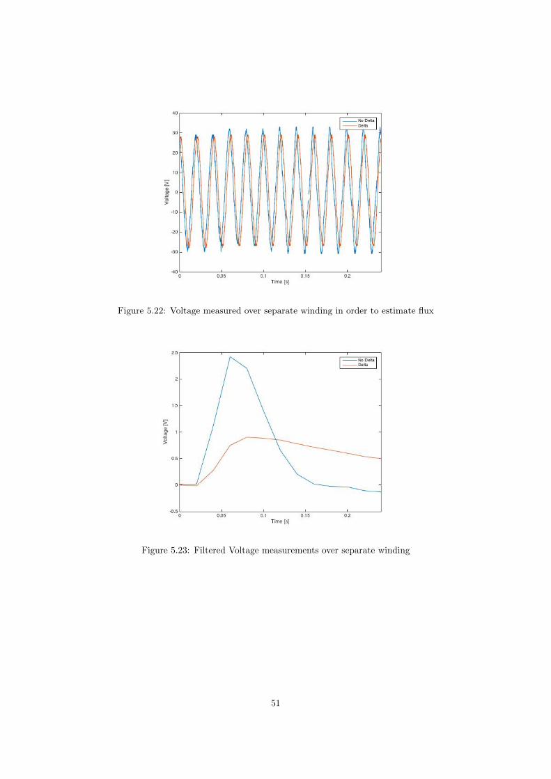
Figure 5.22: Voltage measured over separate winding in order to estimate flux
Figure 5.23: Filtered Voltage measurements over separate winding
51
Chapter 6
Experiment results
This chapter will discuss the results of the experiments in chapter 4, focusing on whythe results became what they are and what the underlying reasons for the results are.
6.1 GIC impact on system
The impact that GIC can have on a power system, mainly through saturation of trans-former cores. The half cycle saturation in the experiments gave rise to current spikesduring the saturated time. It also gave rise to third and sixth harmonics as each leg ofthe core got saturated once per cycle. For a three-phase transformer this gives a thirdharmonic in the neutral. The sixth harmonic that is visible when driving the core intodeep saturation is due to the fact that partial periodic saturation causes second harmon-ics [11]. As the saturation occur three times per cycle, this phenomenon causes a sixthharmonic which is most visible in the compensation windings, as they are connected inseries with one winding around each leg of the transformer.
6.1.1 Single phase transformers
As shown in section 4.3, the single phase transformers are very vulnerable to GIC. Thisis due to the fact that the flux have a closed magnetic circuit to flow in, as the DCflux enters the core in the middle leg and is able to flow back in the outer legs. As themagnetic circuit always is closed for this type of transformer, the flux could correspondto the AC and DC voltages and currents that the core was exposed to, until the corereaches saturation. As the DC offset was increased, the core gradually reached saturationat the parts of the AC cycle where the flux from the AC source plus the flux from theDC source was greater than the maximum amount of flux that could be led through thecore. As the flux from the AC source is alternating, this saturation only occurs whenthe direction of the flux from the AC- and DC source have the same direction and greatenough amplitude.
6.1.2 Three-legged transformer
Compared to the single phase transformers, the three legged 3-phase transformer doesnot have a closed magnetic path for DC flux. The GIC enters all three phases at thesame time and in the same direction, resulting in flux in the same direction in every leg.In other words, there is no leg where the flux can return, hence the magnetic circuit isnot closed. As the magnetic circuit appears as an opened circuit for the DC flux, the
52
GIC has virtually no impact on the three legged transformer, see Figure 4.6 and 4.7.This is in contrast to the single phase- or five legged transformer, where the magneticcircuit is closed for DC flux. Worth mentioning is that the magnetic circuit appears asclosed for AC flux, as the three phases are 120 degrees apart, resulting in an additionof the flux at the top and bottom of the transformer that is always zero in a balancedsystem. This is like three-phase currents that sum to zero at the neutral point.
6.1.3 Five-legged transformer
Just as the single phase transformer, the five legged transformer has two legs at the sideswhere the flux can return. This results in a closed magnetic circuit for the DC flux.Naturally this means that the five legged transformer also is vulnerable to GIC, as itsaturates the core easily, just as for the single phase transformers. The result from thelaboratory studies do look rather different when comparing the single phase transformersand the five legged transformer. This is due to the fact the the five legged transformeris slightly saturated already without any DC offset, probably due to different design ofthe transformer. This can be seen in Figure 4.8.
6.2 GIC mitigation
The tertiary winding was introduced in order to mitigate the negative impact of the GIC.As mentioned earlier this tertiary windings is already present in wye-wye transformers,where its function is to mitigate zero sequence currents. In order to do this, the tertiarywindings from the three phases are simply just connected to each other in a deltaconfiguration. In order to use these windings to mitigate the negative impact of the GIC,the delta connection has to be opened. One end was connected to the neutral point ofthe main windings. The other end was connected to ground. This connection allowed theGIC to flow from the main winding, which usually is the winding on the high voltage sideof the transformer. Then continue to flow through the aeries connected compensationwindings. As the tertiary windings are in series and the high voltage windings are inparallel, seen from the GIC, one third of the voltage in the tertiary windings comparedto the high voltage windings would completely eliminate the flux induced by the GIC.This is not the ordinary voltage the tertiary windings in wye-wye transformers have,but the laboratory studies were made on a series of different voltages on the tertiarywinding, which came to the conclusion that the amount of DC flux reduction in thecore is proportionally related to the voltage of the tertiary windings. Complete DC fluxelimination was accomplished when the tertiary winding had one third of the voltageof the high voltage winding. To more easily grasp this reasoning, the amount of fluxinduced in the core is dependent on the amount of current in the GIC times the numberof turns it does around the core. The GIC first went in one direction around the corein the high voltage windings, then in the other direction around the core in the tertiarywindings. As the tertiary windings are series connected between the neutral point ofthe high voltage windings and ground, the total current around each core is:
GIC ∗ (nhv3
− nt)
Where GIC is the total amount of DC in all three phases, nhv the numbed of turnsof the high voltage windings and nt the number of turns of the tertiary windings. Aseasily seen from this formula, if nt is larger than one third of nhv, the result will benegative. In reality, this corresponds to saturating the core in the other half cycle, asthe core would react as if there was a GIC acting in the opposite direction.
53

6.2.1 Single phase transformers
Just as expected, the mitigation method with the tertiary winding proved to work verywell for the single phase transformers. A partial compensation delayed and mitigatedthe effects of the GIC and a full compensation, meaning:
nt =nhv3
resulted in no difference in the currents of the primary windings, compared to the sce-nario completely without GIC. Running a DC current of 1A through an uncompensatedtransformer, gave the same AC currents, in other words, the same saturation of the core,as running a 4A current through the transformer, when it had a compensation windingnt that was three fourths of nhv/3. Which further proves the statement of a linearrelation between GIC flux mitigation and number of turns on the tertiary windings.Further on, an overcompensating winding was connected, which led to saturation at theother half cycle, just as expected. If the tertiary windings nt is equal to two thirds ofthe high voltage windings, the compensation is exactly double of what it should be.
nhv ∗ nt =2nhv
3
Resulting in an equally large saturation as for no compensation, but in the other halfcycle.
6.2.2 Three-legged transformer
The laboratory results of the three legged transformer with compensation windings hadmore or less no difference from the results without the compensation windings. Thiswas due to the fact that the three legged transformer did not suffer any consequencesfrom a DC offset at this amplitude, as the DC flux circuit of the transformer could beviewed as opened. In other words, the reason that the compensation had no affect onthe three legged transformer was not that the compensation did not work, but ratherthat there was no negative affects to compensate for.
6.2.3 Five-legged transformer
As expected the compensation windings for the five legged transformer showed the sameresult as for the single phase transformer. However, as mentioned in section 5.1, the pointof where the transformers reaches their point of saturation varies between the differenttransformers, resulting in not so similar looking plots. But the purpose of the laboratorystudy was to find how the tertiary windings affected the different transformers, and theeffects of the tertiary windings was close to identical for the single phase transformersand the five legged transformer. This means very obvious reduction of the primaryside current spikes as the compensation windings are connected. Full flux compensationwhen the compensation windings had the optimal number of turns and current spikesat the opposite side of the period when the compensation windings had too many turnsaround the core.
6.3 Summary of steady state
To summarize section 4.1-4.2 is that the five legged 3-phase transformer and the singlephase transformers suffer negative effects as a result of GIC. These negative effects aredue to saturation of the transformers core. However, the saturation can be mitigated
54

or eliminated by leading the GIC through the transformers tertiary windings. Thethree legged 3-phase transformer does not get any positive effects by using the tertiarywindings for GIC mitigation. The reason for this is not that the tertiary windings didnot work for the three legged transformer, but simply that the three legged transformerdid not reach a saturated state as a result of GIC in the laboratory study. It is a lotharder to saturate this type of transformer with a DC, as there is no outer legs for theinduced DC flux to return through.
6.4 Step response without compensation windings
When comparing the four different step responses that were made for the single phasetransformers in section 4.6, a couple of conclusions could be made. Firstly, it was clearthat a transformer exposed to a higher AC voltage would reach its saturation point ear-lier, compared to the same transformer with lower AC voltage. As the saturation pointwas reached earlier, the current step response took a shorter time to reach its steadystate value, due to the earlier drop of inductance. Conclusions that can be made fromthis, is that a transformer with a higher AC voltage will not only be more saturatedwhen the GIC reaches its steady state, but the GIC will also reach its steady statequicker.
Compared to the simulations of power transformers in [8], the rise time in the exper-iments are much shorter. This is due to the big difference in inductance. Apart from thedifferent time scale, a rather similar response is obtained by the experiments and simu-lations. The results from the simulation had almost no increase in current as a result ofthe voltage step before the core was saturated, this is due to the extreme inductance of3500H, while the laboratory results showed a clear increase of current beginning alreadyat the time of the voltage step. The rate of rise of the current increased drastically atthe point of saturation. This increase of current growth in the laboratory result can becompared to the increase of current at the time of saturation in the simulations. Theonly great difference between the laboratory result and the result of the simulations isthat the time constant in the simulations are larger and that the current increases veryslowly until the core gets saturated. These differences are due to the large differences ofinductance but also resistance in the real 2kVA transformer and the transformer of thesimulations. While it is difficult to have 2kVA transformer with the same specificationsas the real transformer, this can be simulated, which is done in Chapter 7.
Figure 6.1: Current response from simulations
55

Figure 6.2: Current response from laboratory study
6.5 Step response with compensation windings
When the compensation windings were used in order to mitigate the negative effectsof the GIC, the current step response got faster. This is, as earlier mentioned, dueto the fact that the inductance seen from the DC source is lowered when the compen-sation windings are implemented. With perfect GIC compensation, the zero sequenceinductance goes to zero. So the positive effects of using the compensation windings tomitigate the negative effects of the GIC is that the core gets less saturated when theGIC reached its steady state. However, a negative side effect of this compensation isthat the GIC will reach its steady state faster. When comparing the time constants ofthe current step response with and without compensation windings, the time constantis approximately 4 time higher for the transformer without GIC compensation. Whichalso can be seen in the formula:
τ =L
R
As L for the uncompensated transformer is 4 times bigger, seen from the DC sourcecompared to the compensated transformer. There is however a small increase of re-sistance in the compensated transformer, as the current also has to travel through thecompensation windings. This can be seen when comparing Figure 5.6 and 5.11, as thesteady state value of the current is slightly smaller for the compensated transformer,compared to the uncompensated.What really is interesting is whether or not the saturation of the core increases fasterfor the compensated or uncompensated transformer. The answer to this is that thesaturation increases at a similar rate. This is due to the fact that the GIC increased4 times faster in the three fourths compensated transformer. Meaning that the threefourths compensated transformer got the same level of saturation as the uncompensatedtransformer when it was exposed to a four times bigger current.Seen from the core perspective, this means that the saturation will increase at a similarrate no matter how much the GIC is compensated for. However, the increase will stopearlier if there is more compensation. Assuming the rise time for an uncompensatedtransformer is α, the rise time for a compensated transformer will be
α ∗ (1 − β)
where β is the amount of compensation, with 1 being a 100%.This formula is also applicable for negative compensation, as subsection 4.6.3 showed.Meaning a negative compensation will increase the time constant of the current step,
56
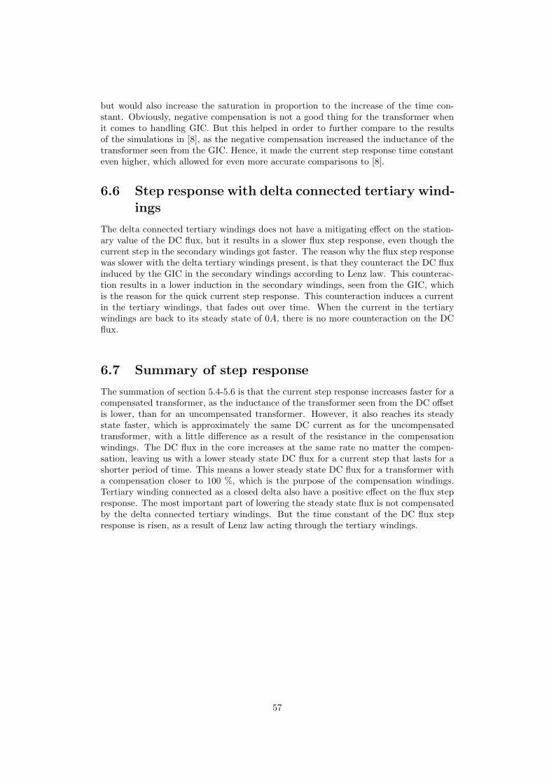
but would also increase the saturation in proportion to the increase of the time con-stant. Obviously, negative compensation is not a good thing for the transformer whenit comes to handling GIC. But this helped in order to further compare to the resultsof the simulations in [8], as the negative compensation increased the inductance of thetransformer seen from the GIC. Hence, it made the current step response time constanteven higher, which allowed for even more accurate comparisons to [8].
6.6 Step response with delta connected tertiary wind-ings
The delta connected tertiary windings does not have a mitigating effect on the station-ary value of the DC flux, but it results in a slower flux step response, even though thecurrent step in the secondary windings got faster. The reason why the flux step responsewas slower with the delta tertiary windings present, is that they counteract the DC fluxinduced by the GIC in the secondary windings according to Lenz law. This counterac-tion results in a lower induction in the secondary windings, seen from the GIC, whichis the reason for the quick current step response. This counteraction induces a currentin the tertiary windings, that fades out over time. When the current in the tertiarywindings are back to its steady state of 0A, there is no more counteraction on the DCflux.
6.7 Summary of step response
The summation of section 5.4-5.6 is that the current step response increases faster for acompensated transformer, as the inductance of the transformer seen from the DC offsetis lower, than for an uncompensated transformer. However, it also reaches its steadystate faster, which is approximately the same DC current as for the uncompensatedtransformer, with a little difference as a result of the resistance in the compensationwindings. The DC flux in the core increases at the same rate no matter the compen-sation, leaving us with a lower steady state DC flux for a current step that lasts for ashorter period of time. This means a lower steady state DC flux for a transformer witha compensation closer to 100 %, which is the purpose of the compensation windings.Tertiary winding connected as a closed delta also have a positive effect on the flux stepresponse. The most important part of lowering the steady state flux is not compensatedby the delta connected tertiary windings. But the time constant of the DC flux stepresponse is risen, as a result of Lenz law acting through the tertiary windings.
57

Chapter 7
Simulations
7.1 Model
The simulations were performed in Matlab and Simulink. Figure 7.1 illustrates theSimulink model that was most commonly used. The same model, with different trans-former parameters was used for simulations of both the small and large transformers.
Figure 7.1: Simulink model of the wye-wye connected single phase 800VA transformerswith DC-offset
7.2 Simulations
In order to apply the results of the laboratory exercises on a large transformer, a Simulinkmodel of a 2.4kVA transformer was made and later reconfigured to 400MVA.
58
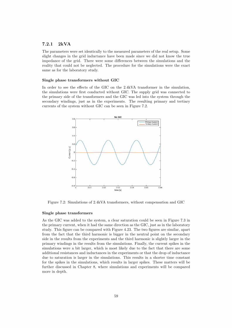
7.2.1 2kVA
The parameters were set identically to the measured parameters of the real setup. Someslight changes in the grid inductance have been made since we did not know the trueimpedance of the grid. There were some differences between the simulations and thereality that could not be neglected. The procedure for the simulations were the exactsame as for the laboratory study.
Single phase transformers without GIC
In order to see the effects of the GIC on the 2.4kVA transformer in the simulation,the simulations were first conducted without GIC. The supply grid was connected tothe primary side of the transformers and the GIC was led into the system through thesecondary windings, just as in the experiments. The resulting primary and tertiarycurrents of the system without GIC can be seen in Figure 7.2.
Figure 7.2: Simulations of 2.4kVA transformers, without compensation and GIC
Single phase transformers
As the GIC was added to the system, a clear saturation could be seen in Figure 7.3 inthe primary current, when it had the same direction as the GIC, just as in the laboratorystudy. This figure can be compared with Figure 4.23. The two figures are similar, apartfrom the fact that the third harmonic is bigger in the neutral point on the secondaryside in the results from the experiments and the third harmonic is slightly larger in theprimary windings in the results from the simulations. Finally, the current spikes in thesimulations were a bit larger, which is most likely due to the fact that there are someadditional resistances and inductances in the experiments or that the drop of inductancedue to saturation is larger in the simulations. This results in a shorter time constantfor the spikes in the simulations, which results in larger spikes. These matters will befurther discussed in Chapter 8, where simulations and experiments will be comparedmore in depth.
59

Figure 7.3: Simulations of 2.4kVA transformers, without compensation windings.
FFT of the single phase transformers waveform
In order to better understand the waveforms of Figure 7.3, an FFT was made in Matlaband is presented in Figure 7.4. The most interesting part of this spectrum is the thirdharmonic of the primary windings, which is a lot larger in the simulations, when com-pared to the experiments. As 7.5 shows, the amplitude of the third harmonic is identicalfor the primary and tertiary current.
Figure 7.4: FFT of 2.4kVA transformers
60
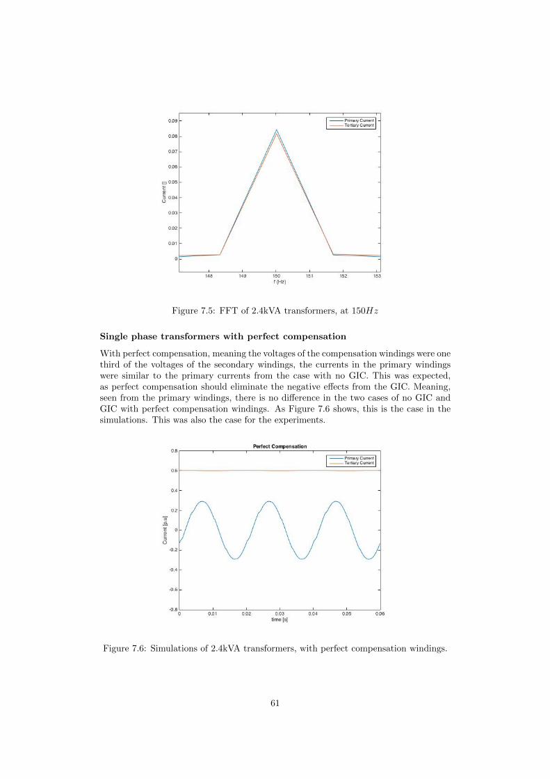
Figure 7.5: FFT of 2.4kVA transformers, at 150Hz
Single phase transformers with perfect compensation
With perfect compensation, meaning the voltages of the compensation windings were onethird of the voltages of the secondary windings, the currents in the primary windingswere similar to the primary currents from the case with no GIC. This was expected,as perfect compensation should eliminate the negative effects from the GIC. Meaning,seen from the primary windings, there is no difference in the two cases of no GIC andGIC with perfect compensation windings. As Figure 7.6 shows, this is the case in thesimulations. This was also the case for the experiments.
Figure 7.6: Simulations of 2.4kVA transformers, with perfect compensation windings.
61
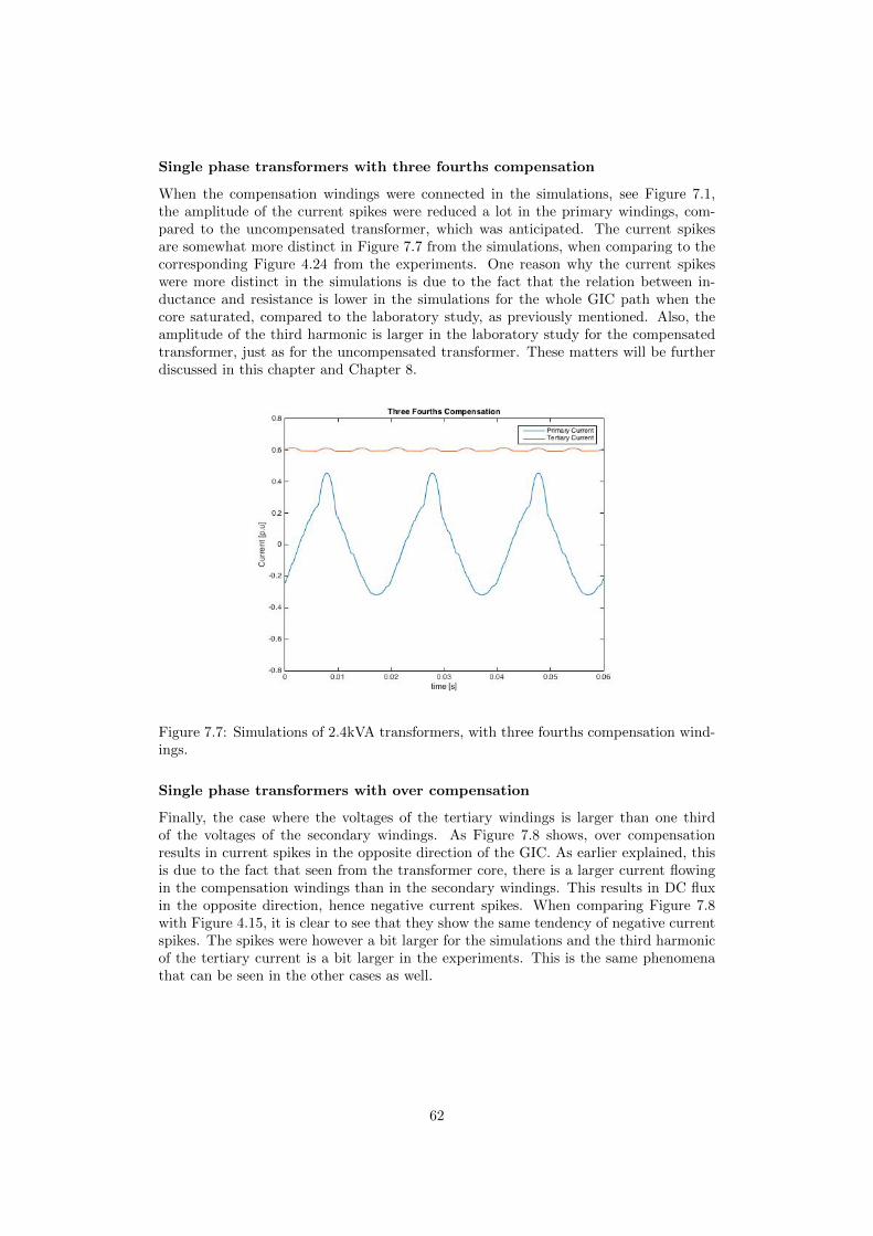
Single phase transformers with three fourths compensation
When the compensation windings were connected in the simulations, see Figure 7.1,the amplitude of the current spikes were reduced a lot in the primary windings, com-pared to the uncompensated transformer, which was anticipated. The current spikesare somewhat more distinct in Figure 7.7 from the simulations, when comparing to thecorresponding Figure 4.24 from the experiments. One reason why the current spikeswere more distinct in the simulations is due to the fact that the relation between in-ductance and resistance is lower in the simulations for the whole GIC path when thecore saturated, compared to the laboratory study, as previously mentioned. Also, theamplitude of the third harmonic is larger in the laboratory study for the compensatedtransformer, just as for the uncompensated transformer. These matters will be furtherdiscussed in this chapter and Chapter 8.
Figure 7.7: Simulations of 2.4kVA transformers, with three fourths compensation wind-ings.
Single phase transformers with over compensation
Finally, the case where the voltages of the tertiary windings is larger than one thirdof the voltages of the secondary windings. As Figure 7.8 shows, over compensationresults in current spikes in the opposite direction of the GIC. As earlier explained, thisis due to the fact that seen from the transformer core, there is a larger current flowingin the compensation windings than in the secondary windings. This results in DC fluxin the opposite direction, hence negative current spikes. When comparing Figure 7.8with Figure 4.15, it is clear to see that they show the same tendency of negative currentspikes. The spikes were however a bit larger for the simulations and the third harmonicof the tertiary current is a bit larger in the experiments. This is the same phenomenathat can be seen in the other cases as well.
62
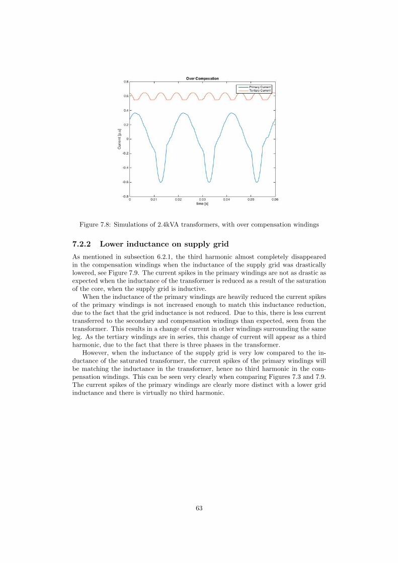
Figure 7.8: Simulations of 2.4kVA transformers, with over compensation windings
7.2.2 Lower inductance on supply grid
As mentioned in subsection 6.2.1, the third harmonic almost completely disappearedin the compensation windings when the inductance of the supply grid was drasticallylowered, see Figure 7.9. The current spikes in the primary windings are not as drastic asexpected when the inductance of the transformer is reduced as a result of the saturationof the core, when the supply grid is inductive.
When the inductance of the primary windings are heavily reduced the current spikesof the primary windings is not increased enough to match this inductance reduction,due to the fact that the grid inductance is not reduced. Due to this, there is less currenttransferred to the secondary and compensation windings than expected, seen from thetransformer. This results in a change of current in other windings surrounding the sameleg. As the tertiary windings are in series, this change of current will appear as a thirdharmonic, due to the fact that there is three phases in the transformer.
However, when the inductance of the supply grid is very low compared to the in-ductance of the saturated transformer, the current spikes of the primary windings willbe matching the inductance in the transformer, hence no third harmonic in the com-pensation windings. This can be seen very clearly when comparing Figures 7.3 and 7.9.The current spikes of the primary windings are clearly more distinct with a lower gridinductance and there is virtually no third harmonic.
63

Figure 7.9: Simulations of 2.4kVA transformers with lowered inductance in feeding grid
7.2.3 Transient behaviour
The transient behavior in the simulations was implemented in the exact same way as inthe laboratory study. The over all time constant was about the same for the laboratorystudies, meaning a rise time of about 100 − 150ms. However, as seen when comparingthe different curves of Figure 7.10, the time constant did not get affected by the primaryAC voltage, which it should have, as the duration of saturation increases with a largerprimary AC voltage. Hence, supposedly lower effective inductance for the GIC. Thereis also no time delay from the time of the step to maximum saturation. This is clearlyseen in Figure 7.10, as the rate of change of the GIC is at its largest at the time of thestep. This indicates that the effective inductance does not depend on the actual GICthat is flowing, but on the estimated steady state value of the GIC, which is most likelydue to a design flaw in the simulations.
64
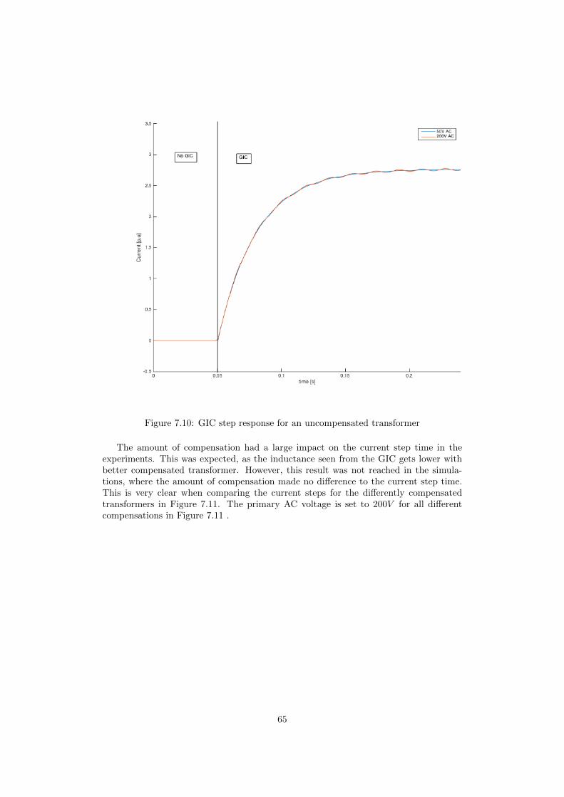
Figure 7.10: GIC step response for an uncompensated transformer
The amount of compensation had a large impact on the current step time in theexperiments. This was expected, as the inductance seen from the GIC gets lower withbetter compensated transformer. However, this result was not reached in the simula-tions, where the amount of compensation made no difference to the current step time.This is very clear when comparing the current steps for the differently compensatedtransformers in Figure 7.11. The primary AC voltage is set to 200V for all differentcompensations in Figure 7.11 .
65
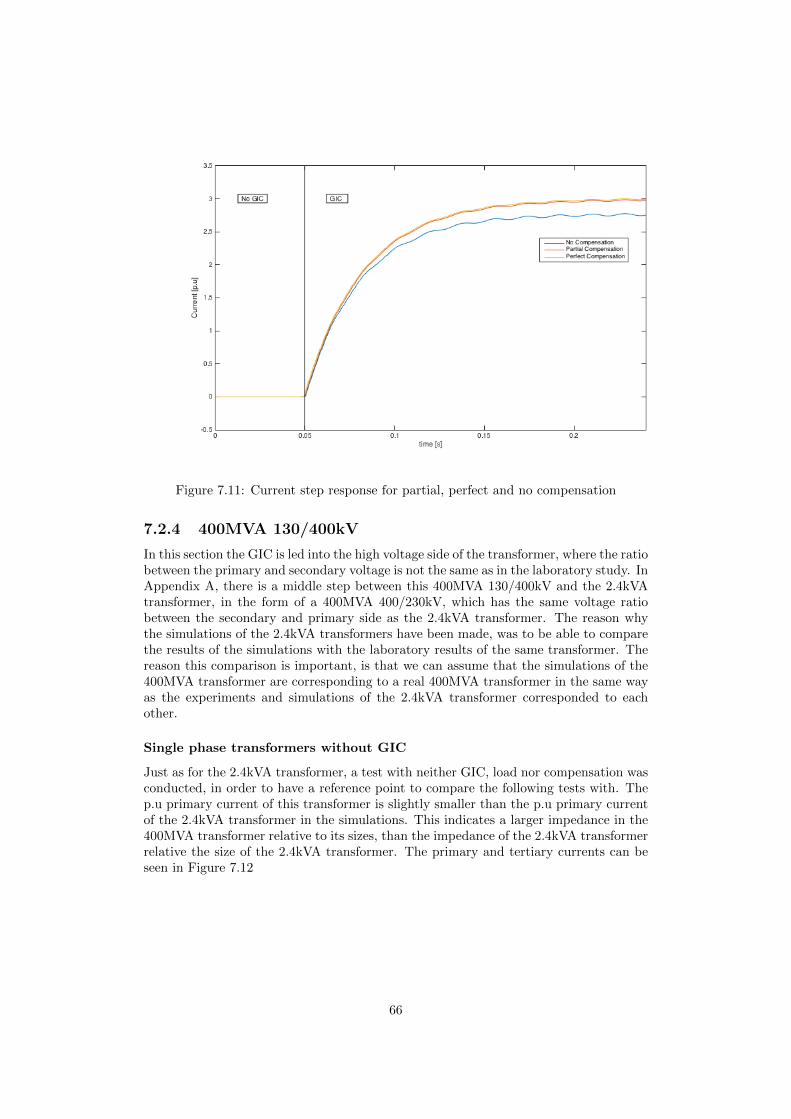
Figure 7.11: Current step response for partial, perfect and no compensation
7.2.4 400MVA 130/400kV
In this section the GIC is led into the high voltage side of the transformer, where the ratiobetween the primary and secondary voltage is not the same as in the laboratory study. InAppendix A, there is a middle step between this 400MVA 130/400kV and the 2.4kVAtransformer, in the form of a 400MVA 400/230kV, which has the same voltage ratiobetween the secondary and primary side as the 2.4kVA transformer. The reason whythe simulations of the 2.4kVA transformers have been made, was to be able to comparethe results of the simulations with the laboratory results of the same transformer. Thereason this comparison is important, is that we can assume that the simulations of the400MVA transformer are corresponding to a real 400MVA transformer in the same wayas the experiments and simulations of the 2.4kVA transformer corresponded to eachother.
Single phase transformers without GIC
Just as for the 2.4kVA transformer, a test with neither GIC, load nor compensation wasconducted, in order to have a reference point to compare the following tests with. Thep.u primary current of this transformer is slightly smaller than the p.u primary currentof the 2.4kVA transformer in the simulations. This indicates a larger impedance in the400MVA transformer relative to its sizes, than the impedance of the 2.4kVA transformerrelative the size of the 2.4kVA transformer. The primary and tertiary currents can beseen in Figure 7.12
66
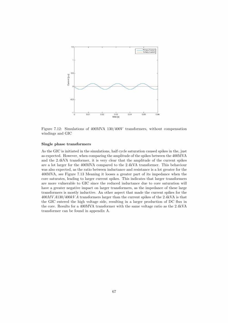
Figure 7.12: Simulations of 400MVA 130/400V transformers, without compensationwindings and GIC
Single phase transformers
As the GIC is initiated in the simulations, half cycle saturation caused spikes in the, justas expected. However, when comparing the amplitude of the spikes between the 400MVAand the 2.4kVA transformer, it is very clear that the amplitude of the current spikesare a lot larger for the 400MVA compared to the 2.4kVA transformer. This behaviourwas also expected, as the ratio between inductance and resistance is a lot greater for the400MVA, see Figure 7.13 Meaning it looses a greater part of its impedance when thecore saturates, leading to larger current spikes. This indicates that larger transformersare more vulnerable to GIC since the reduced inductance due to core saturation willhave a greater negative impact on larger transformers, as the impedance of these largetransformers is mostly inductive. An other aspect that made the current spikes for the400MVA130/400kV A transformers larger than the current spikes of the 2.4kVA is thatthe GIC entered the high voltage side, resulting in a larger production of DC flux inthe core. Results for a 400MVA transformer with the same voltage ratio as the 2.4kVAtransformer can be found in appendix A.
67
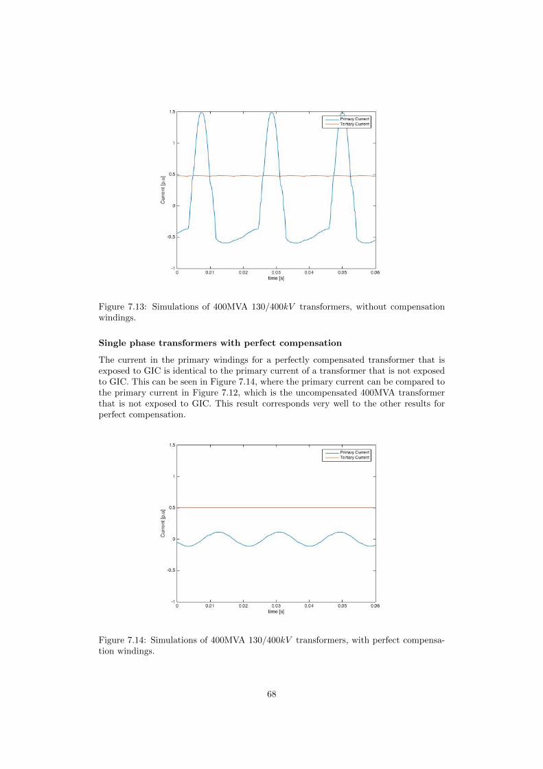
Figure 7.13: Simulations of 400MVA 130/400kV transformers, without compensationwindings.
Single phase transformers with perfect compensation
The current in the primary windings for a perfectly compensated transformer that isexposed to GIC is identical to the primary current of a transformer that is not exposedto GIC. This can be seen in Figure 7.14, where the primary current can be compared tothe primary current in Figure 7.12, which is the uncompensated 400MVA transformerthat is not exposed to GIC. This result corresponds very well to the other results forperfect compensation.
Figure 7.14: Simulations of 400MVA 130/400kV transformers, with perfect compensa-tion windings.
68
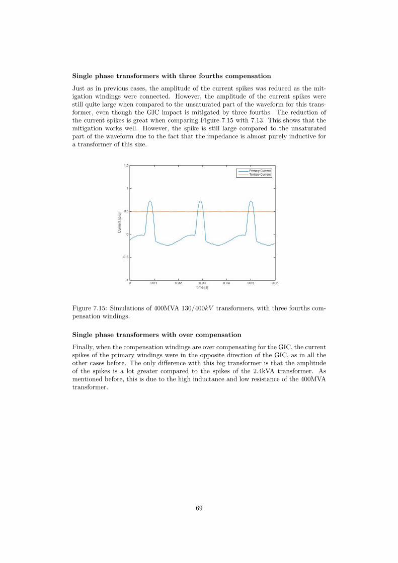
Single phase transformers with three fourths compensation
Just as in previous cases, the amplitude of the current spikes was reduced as the mit-igation windings were connected. However, the amplitude of the current spikes werestill quite large when compared to the unsaturated part of the waveform for this trans-former, even though the GIC impact is mitigated by three fourths. The reduction ofthe current spikes is great when comparing Figure 7.15 with 7.13. This shows that themitigation works well. However, the spike is still large compared to the unsaturatedpart of the waveform due to the fact that the impedance is almost purely inductive fora transformer of this size.
Figure 7.15: Simulations of 400MVA 130/400kV transformers, with three fourths com-pensation windings.
Single phase transformers with over compensation
Finally, when the compensation windings are over compensating for the GIC, the currentspikes of the primary windings were in the opposite direction of the GIC, as in all theother cases before. The only difference with this big transformer is that the amplitudeof the spikes is a lot greater compared to the spikes of the 2.4kVA transformer. Asmentioned before, this is due to the high inductance and low resistance of the 400MVAtransformer.
69

Figure 7.16: Simulations of 400MVA 130/400kV transformers, with over compensationwindings
7.2.5 Transient behaviour
The current step response simulations of the 400MVA transformer showed the sameresults as for the simulations of the 2.4kVA transformer, apart from a lot larger currentstep time constant. The larger time constant was expected, as the ratio between induc-tance and resistance is a lot larger for this 400MVA transformer, compared to the small2.4kVA transformer. The results can be seen in Figure 7.17 and 7.18, which are verysimilar to the results in Figure 7.10 and 7.11, apart from the different time constant.
70
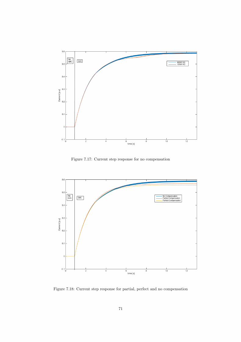
Figure 7.17: Current step response for no compensation
Figure 7.18: Current step response for partial, perfect and no compensation
71
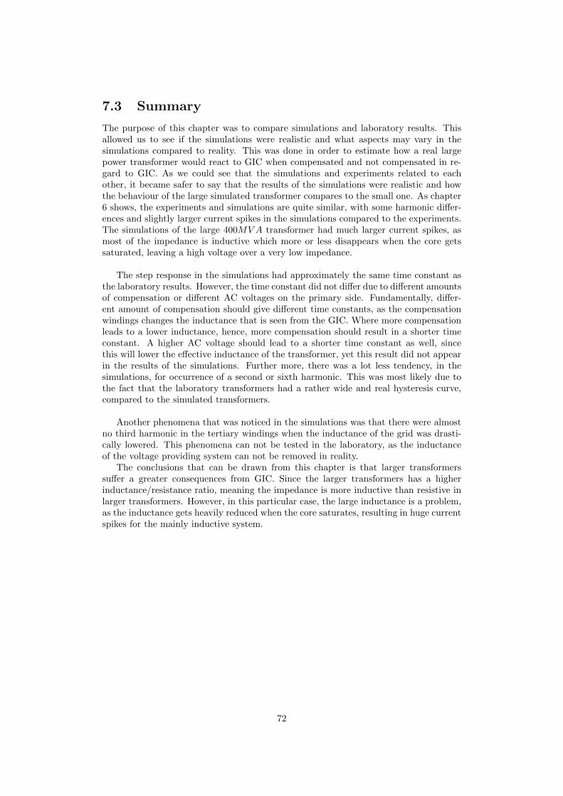
7.3 Summary
The purpose of this chapter was to compare simulations and laboratory results. Thisallowed us to see if the simulations were realistic and what aspects may vary in thesimulations compared to reality. This was done in order to estimate how a real largepower transformer would react to GIC when compensated and not compensated in re-gard to GIC. As we could see that the simulations and experiments related to eachother, it became safer to say that the results of the simulations were realistic and howthe behaviour of the large simulated transformer compares to the small one. As chapter6 shows, the experiments and simulations are quite similar, with some harmonic differ-ences and slightly larger current spikes in the simulations compared to the experiments.The simulations of the large 400MVA transformer had much larger current spikes, asmost of the impedance is inductive which more or less disappears when the core getssaturated, leaving a high voltage over a very low impedance.
The step response in the simulations had approximately the same time constant asthe laboratory results. However, the time constant did not differ due to different amountsof compensation or different AC voltages on the primary side. Fundamentally, differ-ent amount of compensation should give different time constants, as the compensationwindings changes the inductance that is seen from the GIC. Where more compensationleads to a lower inductance, hence, more compensation should result in a shorter timeconstant. A higher AC voltage should lead to a shorter time constant as well, sincethis will lower the effective inductance of the transformer, yet this result did not appearin the results of the simulations. Further more, there was a lot less tendency, in thesimulations, for occurrence of a second or sixth harmonic. This was most likely due tothe fact that the laboratory transformers had a rather wide and real hysteresis curve,compared to the simulated transformers.
Another phenomena that was noticed in the simulations was that there were almostno third harmonic in the tertiary windings when the inductance of the grid was drasti-cally lowered. This phenomena can not be tested in the laboratory, as the inductanceof the voltage providing system can not be removed in reality.
The conclusions that can be drawn from this chapter is that larger transformerssuffer a greater consequences from GIC. Since the larger transformers has a higherinductance/resistance ratio, meaning the impedance is more inductive than resistive inlarger transformers. However, in this particular case, the large inductance is a problem,as the inductance gets heavily reduced when the core saturates, resulting in huge currentspikes for the mainly inductive system.
72
Chapter 8
Simulation results
The results of the simulations were quite similar to the results of the laboratory studywhen comparing the 2.4kVA transformers. When scaling up to a 400MVA transformer,the unloaded transformer had a smaller primary current, due to the high inductance ofthe large transformer.
8.1 Without GIC
Without any GIC or load in the system, the 400MVA transformer has a far lower p.ucurrent on the primary side, due to the very high inductance of the large transformer.
8.2 GIC without mitigation
As the GIC enters the system it is very clear that a transformer with an almost purelyinductive impedance suffer large consequences from core saturation, due to the fact thatalmost all inductance disappears when the core is saturated. Given that the impedanceis almost purely inductive for large transformers as 400MVA, they suffer larger currentspikes compared to a smaller 2.4kVA transformer, where the impedance is a bit moreresistive.
8.3 GIC with perfect mitigation
As perfectly dimensioned compensation windings are introduced to the system no sat-uration occurs and consequently all the negative effects of the GIC disappears, apartfrom a slight heating of the secondary and compensation windings. This happens asa current always will produce some heat when flowing through a resistance. An idealtransformer with zero winding resistance would not have this negative effect, but as realtransformer which always have a small windings resistance will therefor always produceheat from GIC. However, the extreme heating of the huge current spikes disappear, asthere no longer are any current spikes. The heating due to eddy currents and flux flow-ing through material with high reluctance disappear as well. Harmonics also disappear,as that also was a result of the core saturation.
73

8.4 GIC with partial mitigation
The partial compensation reduces the induced DC flux in proportion to the extent of thecompensation. This results in a certain percentage of the current spike being reducedwhen introducing DC flux mitigating windings, which is the compensation windings.As the current spikes of the 400MVA transformer is larger than that of the 2.4kVAtransformer, the amplitude of the current reduction is larger as well. What is worthmentioning is that this conclusion can be drawn when the core is in the verge of satu-ration before the GIC enters the system. If the transformer is far from the saturationpoint, it would require a large DC current in order to reach saturation. This means apartial compensation could be enough to completely drive the transformer out of it sat-urated region. A short explanatory example of this would be if a transformer required10A GIC in order to reach the border of saturation and a GIC of 20A entered the systemit would go into saturation. However, if compensation windings with only one sixth ofthe voltage of the entering windings would be introduce, the negative effects of the GICwould disappear. As 1
2 compensation with 20A GIC would have the same effect on thecore as 10A GIC without compensation. Leaving us with no saturation.
8.5 Grid impedance
Results that could be drawn form the simulations but not the laboratory study wasthe impact the inductance in the supply grid had on the currents in the transformer.The results of these simulations were that the grid inductance had a huge impact onthe systems third harmonics. If the grid reactance was removed, there were no thirdharmonics at all in either the primary, secondary or tertiary windings of the system. Asthe reactance of the grid was increased, the amplitude of the third harmonics increasesas well. Note that the reactance is 3 times larger for the third harmonic compared tothe fundamental, as it is frequency dependent.
8.6 Transient behaviour
The transient behaviour for the small transformer were similar to the results acquiredfrom the laboratory studies. However, the time constant of the current step responsesdid not vary as the AC voltage on the primary side or the amount of compensation waschanged. These factors did change the time constant in the laboratory section and wereexpected to do so in the simulations as well.The upscaling to a 400MVA transformer provided the same shape of the current stepresponse as for the 2.4kVA, with the difference being a longer time constant for the largetransformer.
74

Chapter 9
Conclusions
This is the chapter where conclusions are made based on the results of this thesis.
9.1 GIC Effects
GIC are a concern for the power industry because GIC in the power system can leadto severe consequences. The most common effects that this study has looked into isheating, harmonics and reactive power demand, which all are a result of transformercore saturation due to GIC.
9.1.1 Experimental conclusions
The laboratory measurements showed that the effect of GIC depends on the type oftransformer. The three legged 3-phase transformer suffered almost no consequences dueto the GIC. Since the magnetic flux of every phase is directed in the same way for theGIC combined with the fact there are only three legs as well as three phases, there is nopath for the flux to return. Given this, the core does not provide a closed magnetic loopfor the flux, which forces the flux to flow through surrounding material in order to closethe magnetic loop. As the surrounding material has a reluctance that is far greaterthan the reluctance of the core, the DC flux would need a very high magnetomotiveforce (MMF) in order to become great enough to saturate the core. As it is very hard tosaturate the core with DC flux for a three legged 3-phase transformer, these transformersare almost immune to GIC. When it comes to the five legged 3-phase transformer andthe single phase transformer, the GIC had a significant negative impact. This is due tothe fact that both of these transformers have outer legs, where the DC flux can flow,in other words, theses transformers provide the DC flux with a closed magnetic circuit.The most visible signs of saturation was current spikes in the magnetization current andharmonics in all currents, which is a direct result of core saturation. As larger GIC wasinduced to the system, larger current spikes and harmonics followed.
9.1.2 Simulation conclusions
The simulations provided the same conclusions as the laboratory study, with some addi-tional information regarding the third harmonic. In addition to the laboratory results,the simulation showed that when the inductance of the supply grid was drastically lower,the third harmonic due to the GIC disappeared. Lower grid inductance also results inhigher current spikes as the total combined inductance seen from the primary currentis lower. The reason why the amplitude of the current spike is lowered when the supply
75
grid is inductive is that the total inductance seen from the GIC is larger if the grid has alarger inductance. Which results in a larger time constant, hence a slower step responsefor the GIC. As the saturation only last for a small part of the period, generally about2−3ms, the step does reach a lower point when the time constant is larger. This rise ofthe time constant is the reason for the larger third harmonic as well, since the currentstep is not large enough to match the drop of inductance, resulting in reduced currentsin the secondary and tertiary side of the transformer.
9.1.3 Summary of GIC effects
Conclusions that can be drawn regarding the effect of GIC on an uncompensated systemwith the support of simulations and laboratory study is the following. As the GICproduces a DC flux offset in the transformer core, the core may reach saturation whenthe AC and DC flux have the same direction. This saturation leads to current spikesand eddy currents, which creates hot spots that can severely damage the transformer. Italso leads to second harmonics, as well as small sixth harmonics in the tertiary windings.Given that the system providing the primary windings with voltage is inductive, therewill also be a third harmonic in all windings. In a non ideal system, which all realsystems are, there will always be some inductance in the supply system. The ratiobetween the inductance of the supply system and the inductance of the primary side ofthe transformer sets the amplitude of the third harmonic. If the transformer inductanceis large and the grid inductance is small, the third harmonic will be small.
9.2 GIC Mitigation
The effects of compensation windings on a transformer that is being exposed to GIC hasbeen studied extensively. When it comes to mitigating the DC flux that is produced inthe transformer core by GIC the compensation windings are proven to be very useful.However, as the delta connected tertiary windings are opened in order to make thesecompensation windings, some attributes of the delta connection are lost. Among those,the ability to compensate for zero sequence currents.
9.2.1 Experimental conclusions
The laboratory studies showed that the amplitude of the current spike and the ampli-tude of the harmonics are reduced when compensation windings are implemented in thetransformers, due to the fact that the compensation windings mitigate the core satura-tion. If assuming the transformer is on the point of saturation before the GIC entersthe system, the amount of mitigation is linear to the size of the compensation windingscompared to the size of the windings the GIC enters the transformer through. If thevoltage of the compensation windings is one third of the voltage of the windings wherethe GIC enters the transformer, a perfect DC flux compensation will be performed. Theamount of flux mitigated will always be linear in relation to the size of the compensationwindings. However, the amount of prevented saturation does not follow this formula, asthere is no guarantee that the core is on the verge of saturation without GIC, which itwould have to be in order to saturate for every DC current apart from 0A. When the dcoffset is large enough to drive the core into saturation, there is a linear relation betweensize of the compensation windings and the amount of saturation. Given this informa-tion, it is not necessary to have perfect compensation windings in order to completelyavoid saturation.
76
A brief example of this is if a transformer that can handle a DC offset of 10A getsexposed to a DC offset of 30A. Without any compensation, the core would be drivendeep into saturation and with perfect compensation the GIC would not drive the coreinto saturation. However, a partial compensation would have the exact same effect asthe perfect compensation, given that the compensation windings have between 2/3 and4/3 number of turns in relation to the secondary winding. As this would result in thesame amount of flux as a GIC between 10A and −10A.
9.2.2 Simulation conclusions
The simulations provided the same information as the experimental studies, whichstrengthen the conclusions made in the laboratory. In addition to experimental conclu-sions, the simulations gave an insight in how GIC effects transformers of different sizes,most importantly large transformers that are used in the power system, eg. 400MVAAs the transformer gets larger, the ratio between reactance and resistance X
R gets larger.A larger ratio is usually desirable as it results in less power losses. However in the caseof core saturation, the current spikes get larger as this ratio gets larger, due to the factthat a larger part of the transformer impedance disappears at the point of saturationif the transformer is more inductive. Given this, the larger transformer that is used,the more important it is to compensate for GIC, as they are more vulnerable to coresaturation.
9.2.3 Summary of GIC mitigation
Conclusions that can be drawn regarding the effect of DC flux mitigation windings ona system with the support of simulations and laboratory study is the following. Theamount of mitigation of DC flux in the core is proportionally related to the size ofthe compensation windings. This implies that partial compensation can be enough tocompletely prevent the core from saturating, given that the transformer does not operateon the very edge of saturation. In other words, as long as the DC flux is small enough thatthe total magnitude of the DC flux added to the AC flux never gets larger than the fluxneeded to saturate the core, the transformer will not suffer negative consequences due tocore saturation. Given this information, partial DC flux compensation is in many casesenough to completely prevent the core from saturating. The larger the transformer, themore important the mitigation windings are. As larger transformer usually have a largerinductance to resistance ratio, resulting in larger current spikes if the core would getsaturated. However, it is very important to remember that the delta connected tertiarywindings loose their ability to compensate for unsymmetrical faults as this re-connectionto GIC compensation windings is made. As unsymmetrical faults occur quite often andGIC is a rare problem, it might not be a good idea to do this re-connection withoutimplementing something in order to take care of the zero sequences currents that arisefrom unsymmetrical faults. This could be solved with either a capacitor that leads theAC in i closed delta and blocks the DC. Or by implementing the GIC compensationwindings as a fourth set of windings, allowing us to perfectly compensate for the GICwhile still keeping all the positive aspects of the delta connected tertiary windings.
9.3 Transient behaviour
Another important aspect is the transient behaviour of the DC current and flux, wherethe compensation windings have both positive and negative effects. Aspects that wereconsidered in the transient behaviour is current and flux step response, steady state
77

value and the impact of delta connected tertiary windings compared to compensationwindings.
9.3.1 Delta windings
The removal of the delta connected tertiary windings when implementing the compensa-tion windings does have some effects on the transient behaviour. The tertiary windingsproduce a faster GIC step response, this behaviour disappears when the delta connec-tion is removed, which is good. However, the reason for this fast current step responseis that the delta connected windings counteract the DC flux by inducing an oppositecurrent in the delta. This counteraction is great enough to make the flux step responseslower compared to the case without a delta connection. As the core saturation hasmuch worse impact on the system, the total outcome of removing the delta windings isnegative in this aspect.
9.3.2 Mitigation windings
The compensation windings had a positive impact on the steady state value of the DCflux. However, the time constant of the flux step response is lowered when compensationwindings are implemented. This is due to the fact that the inductance seen from theDC offset is lowered as compensation is implemented. Which results in a shorter timeconstant for the DC current, which reaches the same steady state with or withoutcompensation. The lowered DC inductance resulting in the shorter current step timeconstant, which is also the reason for the shorter flux step time constant, as the timeconstant for the flux is the same as for the current, when no delta connections or largeloads are present. However, it is not necessary that the actual derivative of the flux stepis higher with compensation as the steady state value of the DC flux is lowered. The finalresults of the laboratory study showed that the flux step derivative does not change whencompensation windings are implemented. Meaning the compensation windings have noimpact of the rate of DC flux change, but shortens the time of the change, which ofcourse results in a lower steady state flux. In conclusion, the implementation have noeffect on the steady state current or rate of change for the DC flux. It does have anegative impact on the rate of change of the current. However, it does have a positiveimpact on the steady state flux, which is of greater importance than the current steptime constant.
9.3.3 Conclusions of transients
When comparing the positive effects of the compensation windings and the delta con-nected windings for the transient behaviour, it seems to be worth to reconnect the deltawindings to compensation windings. As according to the results of this study, the com-pensation windings provide a greater positive effect than what the delta windings do.The possible solution would be a transformer with both delta and compensation wind-ings, as this implementation would make the DC flux step both slower and lower. Itwould also keep the transformers ability to compensate for zero sequence currents dueto unsymmetrical faults. However, this implementation would come with a great cost,as new transformers with four sets of windings would have to be constructed.
9.4 Harmonics
The most noticeable harmonics in this study are the second and third harmonics. Thesecond harmonic is a result of deep saturation and appears when a transformer is driven
78
into saturation. The third harmonic appears when the core is driven into saturation aswell, but it is not a direct result of the saturation. If the supply grid has no inductancethere will be no third harmonic when the core saturates. The sixth harmonic in thetertiary windings is a result of a second harmonic in each phase of the tertiary windingsdue to deep saturation. As the phases are 120 degree apart and in series, these 3-phaseshifted second harmonics will appear as a sixth harmonic.
79

Chapter 10
Future Work
This study has further given rise to the interest of future work regarding the subject ofDC flux mitigation with compensation windings.
A FEM model of the flux in the core and its surrounding material would be of greatinterest. As this could show how the spread of saturation in the core and which cornersthat saturates first. A FEM model of how the heat spreads would be interesting as well.As this would show where hot spots in the transformer will occur.
Further research of the implementation of a capacitance between the neutral pointof the secondary windings and ground would also be of great interest. Focusing on ifthere are sizes of the capacitance that can lead the AC in a delta while blocking the DCwithout resulting in resonant ringing.
Studies of the transformer behaviour for lower frequencies could be of great value.Apart from the step response, the system is viewed as resistive for the GIC, as it is DCor very low frequent AC. However, GIC with frequencies high enough to get affected bythe systems inductance could be induced. Hence laboratory studies concerning at whatfrequency the inductive part becomes large enough to not view the system as purelyresistive would be interesting.
A study of a transformer with both delta connected tertiary windings and compensa-tion windings implemented would be of great interest. This type of transformer is verylikely to be able to handle zero sequences currents while still possessing the ability tocompensate for the negative effects of the DC flux that is produced by GIC. Preliminaryresults from experiments that were made and is presented in this chapter, as it needs alot of future work. As Figure 10.1 shows, the GIC current step is a lot faster than thecase without a delta, see Figure 5.6, as the delta counteracts the flux induced by theGIC and thereby lowers the inductance seen in the transformer from the GIC.
80
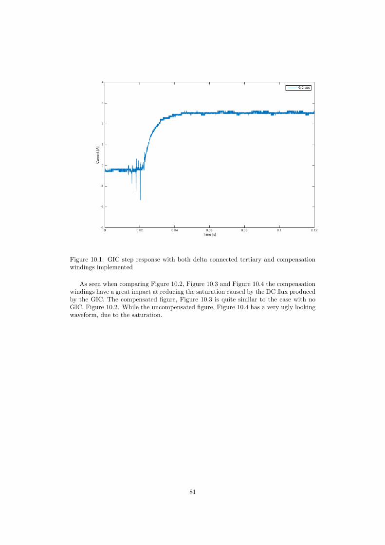
Figure 10.1: GIC step response with both delta connected tertiary and compensationwindings implemented
As seen when comparing Figure 10.2, Figure 10.3 and Figure 10.4 the compensationwindings have a great impact at reducing the saturation caused by the DC flux producedby the GIC. The compensated figure, Figure 10.3 is quite similar to the case with noGIC, Figure 10.2. While the uncompensated figure, Figure 10.4 has a very ugly lookingwaveform, due to the saturation.
81
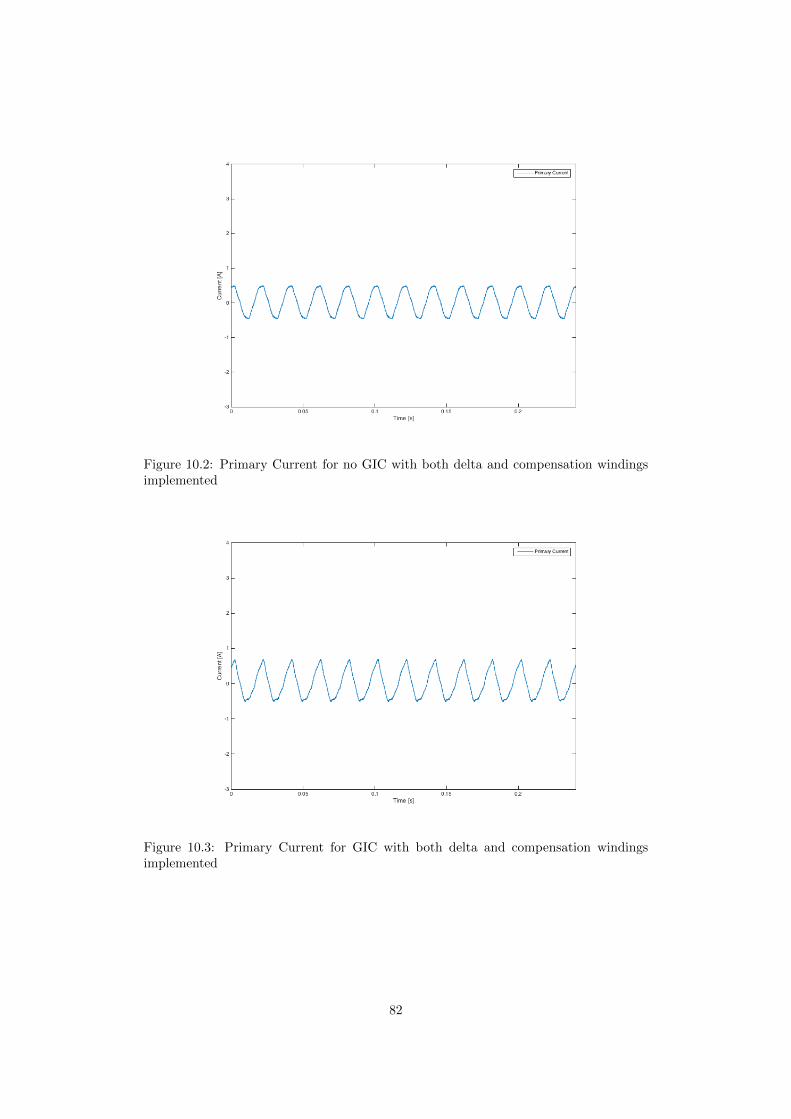
Figure 10.2: Primary Current for no GIC with both delta and compensation windingsimplemented
Figure 10.3: Primary Current for GIC with both delta and compensation windingsimplemented
82
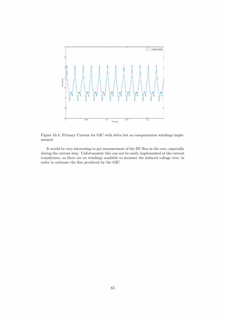
Figure 10.4: Primary Current for GIC with delta but no compensation windings imple-mented
It would be very interesting to get measurement of the DC flux in the core, especiallyduring the current step. Unfortunately this can not be easily implemented at the currenttransformer, as there are no windings available to measure the induced voltage over, inorder to estimate the flux produced by the GIC.
83

Appendices
84
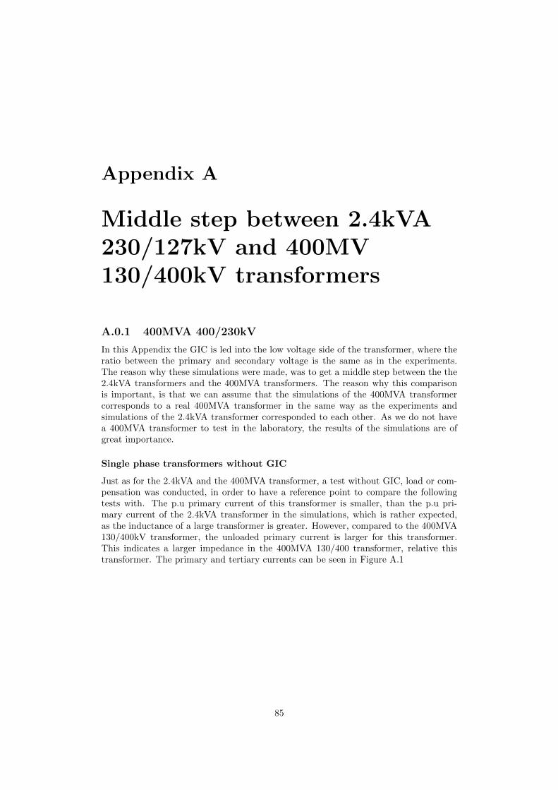
Appendix A
Middle step between 2.4kVA230/127kV and 400MV130/400kV transformers
A.0.1 400MVA 400/230kV
In this Appendix the GIC is led into the low voltage side of the transformer, where theratio between the primary and secondary voltage is the same as in the experiments.The reason why these simulations were made, was to get a middle step between the the2.4kVA transformers and the 400MVA transformers. The reason why this comparisonis important, is that we can assume that the simulations of the 400MVA transformercorresponds to a real 400MVA transformer in the same way as the experiments andsimulations of the 2.4kVA transformer corresponded to each other. As we do not havea 400MVA transformer to test in the laboratory, the results of the simulations are ofgreat importance.
Single phase transformers without GIC
Just as for the 2.4kVA and the 400MVA transformer, a test without GIC, load or com-pensation was conducted, in order to have a reference point to compare the followingtests with. The p.u primary current of this transformer is smaller, than the p.u pri-mary current of the 2.4kVA transformer in the simulations, which is rather expected,as the inductance of a large transformer is greater. However, compared to the 400MVA130/400kV transformer, the unloaded primary current is larger for this transformer.This indicates a larger impedance in the 400MVA 130/400 transformer, relative thistransformer. The primary and tertiary currents can be seen in Figure A.1
85

Figure A.1: Simulations of 400MVA 400/230V transformers, without compensationwindings and GIC
Single phase transformers
As the GIC is introduced to the simulations, the primary winding got current spikes,just as expected. When comparing the amplitude of the spikes between this transformerand the 2.4kVA transformer, it is very clear that the amplitude of the current spikes area lot larger for the 400MVA compared to the size of the sinusoidal current, however themaximum amplitude of the current spike in p.u are quite similar for the two cases. Thisbehaviour was expected, as the ratio between inductance and resistance is a lot greaterfor the 400MVA, see Figure A.2. Hence it looses a greater part of its impedance whenthe core saturates, leading to larger difference in current between the saturated andunsaturated areas. However, when the comparisons are made between this transformerand the 400MVA 130/400kV transformer, it is clear that the 400MVA 130/400kV trans-former suffers greater negative impact due to the GIC. This is due to the fact that theGIC enters the high voltage side of the 400MVA 130/400kV transformer, meaning theGIC will make a larger number of turns around the core, resulting in a deeper saturationthan for the 400MVA 400/230kV transformer.
86

Figure A.2: Simulations of 400MVA 400/230kV transformers, without compensationwindings.
Single phase transformers with perfect compensation
Just as expected, after studying the previous results of perfect compensation, the currentin the primary windings for a perfectly compensated transformer that is exposed to GICis identical to the current of a transformer that is not exposed to GIC. This can be seenin Figure A.3, where the primary current can be compared to the primary current inFigure A.1, which is the uncompensated 400MVA transformer that is not exposed toGIC.
Figure A.3: Simulations of 400MVA 400/230kV transformers, with perfect compensationwindings.
87
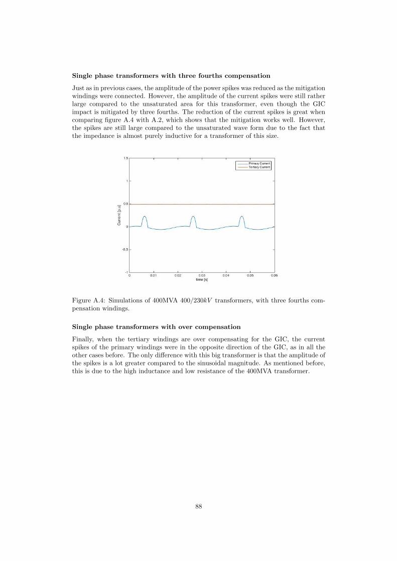
Single phase transformers with three fourths compensation
Just as in previous cases, the amplitude of the power spikes was reduced as the mitigationwindings were connected. However, the amplitude of the current spikes were still ratherlarge compared to the unsaturated area for this transformer, even though the GICimpact is mitigated by three fourths. The reduction of the current spikes is great whencomparing figure A.4 with A.2, which shows that the mitigation works well. However,the spikes are still large compared to the unsaturated wave form due to the fact thatthe impedance is almost purely inductive for a transformer of this size.
Figure A.4: Simulations of 400MVA 400/230kV transformers, with three fourths com-pensation windings.
Single phase transformers with over compensation
Finally, when the tertiary windings are over compensating for the GIC, the currentspikes of the primary windings were in the opposite direction of the GIC, as in all theother cases before. The only difference with this big transformer is that the amplitude ofthe spikes is a lot greater compared to the sinusoidal magnitude. As mentioned before,this is due to the high inductance and low resistance of the 400MVA transformer.
88

Figure A.5: Simulations of 400MVA 400/230kV transformers, with over compensationwindings
89

Appendix B
List of material
Table B.1: Equipment# Item3 Single phase trafo, 800VA1 Three legged trafo, 2.4kVA1 Five legged trafo, 2.4kVA1 Synchronous generator, 200kVA1 Variac2 ASEA Three phase trafo, 2kVA2 12V car battery1 circuit board7 Multimeter2 Fluke AC current probe2 Kyoritsu AC/DC clamp adapter1 Tektronix differential probe1 Esselte-studium differential probe1 ASEA-education load capacitor1 Tramo-ETV load inductor2 Terco load resistance1 Powerbox-6303DS
90
Bibliography
[1] M Alakula and S Lindhal ”METHOD AND EQUIPMENT FOR THE PRO-TECTION OF POWER SYSTEMS AGAINST GEOMAGNETICALLY INDUCEDCURRENTS”http://patents.justia.com/patent/20070217103 Application nr: 20070217103November 7, 2006
[2] D. H. Boteler, R. J. Pirjola and H. Nevanlinna”The effects of geomagnetic disturbances on electrical systems at the earth’s sur-face”Geomagnetic Laboratory, Geological Survey of Canada, 1 Observatory Cres., Ot-tawa, Ontario, K1A 0Y3 CanadaFinnish Meteorological Institute, P.O Box 503, FIN-00101 Helsinki, Finland
[3] D. H. Boteler”Geomagnetic Hazards to Conducting Networks”Geomagnetic Laboratory, geological Survey of Canada 7 Observation Crescent, Ot-tawa, Ontario.K1A 0Y3, Canada E-mail: [email protected]
[4] D. H. Boteler”Assessment of Geomagnetic Hazard to Power Systems in Canada”Geomagnetic Laboratory, geological Survey of Canada 7 Observation Crescent, Ot-tawa, Ontario.K1A 0Y3, Canada E-mail: [email protected]
[5] R. J. Pirjola and D. H. Boteler.”Geomagnetically induced currents in european high-voltage power systems,”Electrical and Computer Engineer-ing, 2006. CCECE ’06. Canadian Conference on.IEEE, May 2006, pp. 1263-1266.
[6] NASASolar Storm and Space Weatherhttps://www.nasa.gov/mission pages/sunearth/spaceweather/index.html#q22016.04.26
[7] R. J. Pirjola (2012).Geomagnetically Induced Currents as Ground Effects of Space Weather, Space Sci-ence, Dr. Herman J. Mosquera Cuesta (Ed.), ISBN: 978-953-51-0423-0, InTech,Available from:
[8] D. H. Boteler, Senior Member, IEEE, and E. Bradley”On the Interaction of Power Transformers and Geomagnetically Induced Currents”IEEE TRANSACTIONS ON POWER DELIVERY, VOL. 31, NO. 5, OCTOBER2016
91
[9] O SamuelssonDivision of Industrial Electrical Engineering and Automation Lund University ”Ge-omagnetic disturbances and their impact on power systems”CODEN:LUTEDX/(TEIE-7242)/1-21/(2013)
[10] R. Lordan”Literature Survey on Transformer Models for the Simulation of ElectromagneticTransients with Emphasis on Geomagnetic-Induced Current (GIC) Applications”EPRI, Palo Alto, CA: 2012. 1025844.pp.2
[11] S HodderHydro One Networks, Inc.Bogdan Kasztenny, Normann Fischer, and Yu Xia, Schweitzer Engineering Laborato-ries, Inc. ”Low Second-Harmonic Content in Transformer Inrush Currents – Analysisand Practical Solutions for Protection Security” NOVEMBER 2014
92