Embed Size (px)
Citation preview
Mitigation of Voltage Sags by Dynamic Voltage
Restorer
Jeyagopi Raman and Arwinder Singh Faculty of Engineering, INTI International University, Nilai, Negeri Sembilan, Malaysia
Email: {jeyag.raman, arwinders.jigiris}@newinti.edu.my
Abstract—Voltage sag is the most severe type of power
quality disturbance faced by many commercial and
industrial customers. The proliferation of voltage sag load
equipment used in industrial plants may cause tremendous
economic and financial losses up to millions of dollars
attributed to a single disruption. Therefore, it is very
important to mitigate the impact of voltage sags on sensitive
equipment. In this paper, Dynamic Voltage Restorer (DVR)
is used to mitigate the voltage sag during fault condition.
DVR is considered to be the most efficient and effective
mitigation device. The method to calculate the DVR devices
for the fault calculation, were consider in this paper, as well
as the control strategy. The mitigation technique was
applied to an IEEE 30-buses electrical network to illustrate
its application.The results show that the mitigation
technique is able to mitigate voltage sag. Analyses of the
voltage sag magnitude had shown the different with and
without DVR for the network system.
Index Terms—dynamic voltage restorer, voltage sag, power
quality, voltage sags, balanced and unbalanced faults
I. INTRODUCTION
Power quality is a customer-driven issue concerning
the characteristics of power supply that affect the
performance of customer equipment such as micro-
electronic devices and power electronic devices.
Unexplained equipment trips or shutdowns; occasional
equipment damage or component failure; erratic control
of process performance; random lockups and data errors,
power system component overheating are mainly caused
by poor power quality [1], [2].
Due to the associated significant financial losses,
problems of the quality of power delivered to the
customers have become an important issue. Recent
studies show that 80-90% of all power quality issues are
from onsite problems, rather than utility problems [3].
Harmonics, voltage sags, voltage swells and short
interruptions are the most common types of
voltageabnormalities [3]. Voltage sag accounts for the
highest percentage of equipment interruptions, about 31%
[4].
Voltage magnitude and duration are essential
characteristics of voltage sag. The voltage sag magnitude,
which is the remaining voltage during the event, depends
not only on the fault type and fault location but also on
Manuscript received June 11, 2013; revised August 20, 2013.
other factors such as pre-fault voltages, transformer
connection and fault impedance. The duration of voltage
sag is defined as the time during which the voltage
magnitude (RMS voltage) is below a given voltage
threshold. In the event of a fault in the network, the
ensuing voltage sag will last until protective devices acts
to interrupt the flow of fault current.
Due to this uncontrollable voltage sag phenomena,
sensitive equipment used in industrial plants, such as
process controllers, adjustable speed drives, computers,
programmable logic controllers, robotics, banks, data
centers and customer service centers may cause
tremendous economic and financial losses up to millions
of dollars attributed to a single disruption [5], [6].
An increasing demand for high quality, reliable
electrical power an increasing number of distorting loads
have led to an increased awareness of power quality by
customer and utilities. Therefore it is very important to
mitigate the impact of voltage sags on sensitive
equipment. For voltage sag mitigation, power electronic
or static controllers in medium and low voltage
distribution systems use mitigation devices for the
purpose of supplying a nominal voltage [7], [8]. The most
commonly used devices to mitigate voltage sag are the
DVR and STATCOM as illustrated in [8], [9].
In this paper, a series compensation mitigation device,
commonly called dynamic voltage restorer (DVR), has
been applied as a definitive solution due to the
advantages of the series compensation over the shunt
compensation [9], [10]. DVR is commonly used to
mitigate voltage sag, voltage swell, voltage harmonic and
voltage fluctuations as it is a compensating type
mitigation device.
II. DYNAMIC VOLTAGE RESTORER
As shown in Fig. 1, a DVR is a device that injects a
dynamically controlled voltage Vinj(t) in series to the bus
voltage by means of a booster transformer. The DVR is
designed to feed an additional voltage source between
system feeder and load site. The feature of DVR is to
improve the voltage magnitude when the load in down-
stream of its series connection.
Normally, the energy storage capacity of DVR will be
sufficient enough to compensate a 50% of voltage sag for
up to 10 cycles. This is enough to recover the fault.
Although it may be rated to compensate up to a 90%
voltage drop, DVR does not support complete outages. A
Journal of Automation and Control Engineering Vol. 2, No. 1, March 2014
49doi: 10.12720/joace.2.1.49-53©2014 Engineering and Technology Publishing
typical power range to be covered by DVR is from 3
MVA up to 50 MVA.
Figure 1. Basic structure of DVR
The DVR consists of the following components [10]:
A. Energy Storage Unit
During voltage sag condition, energy storage is used to
provide the shortage of missing energy. Commercially
available DVRs use large capacitor banks. The capacity
of the energy storage device has a big impact on the
compensation capability of the system. DVRs can be
configured alternatively to use line energy supply, that is,
they absorb the energy that is to be injected from the
utility feeder itself into the distribution circuit.
B. Voltage Source Inverter
The DC voltage is converted from the energy storage
unit to a controllable AC voltage which is to be injected
to the line voltage.
C. Filter Circuit
Normally, a second-order LC filter is introduced
between the inverter and the transformer to cancel high
frequency harmonic components in the inverter output
voltage.
D. Bypass Switches and Control Circuits
The DVR may be configured to operate as a standby
compensator where the inverter is passive in the circuit
until triggered by a voltage sag event. Alternatively, the
DVR may be working continuously during normal and
abnormal conditions.
E. Injection Transformer
Its primary connected in parallel to the output of the
VSI and its secondary connected in series between the
Point of Common Coupling (PCC) and the load bus, and
which injects the controllable three phase voltage VDVR to
the PCC voltage.This ensures that the load bus voltage,
VL remains almost unaffected by the sag condition.
III. CONTROL STRATEGY
Different type of voltage sag and load conditions can
limit the possibility of compensating voltage sag.
Therefore, the control strategy depends on the type of
load characteristics. There are three different methods to
inject DVR compensating voltage.
A. Pre-fault Compensation
Pre-fault control strategy restores voltage to the pre-
fault value, i.e. both sag magnitude and phase shift are
compensated. The reference voltage is set as pre-fault
voltage magnitude and phase angle. Fig. 2 shows the
single-phase vector diagram of pre-fault compensation
method [10].
Figure 2. Pre-fault compensation method.
B. In-phase Compensation
In-phase voltage compensation method restores
voltage to be in phase with the voltage sag. In other
words, the phase angle will be same as the angle of
sagged voltage while the voltage magnitude is restored to
pre-fault value. Fig 3 shows the single-phase vector
diagram for in-phase compensation method [10].
Figure 3. In-phase compensation method
For restore the voltage sag or disturbance by applying
pre-sag and in-phase compensation method, must inject
active power to loads. The disadvantage of the active
power is the amount of injection which depends on the
stored energy in the storage unit. DVR restoration time
and performance are important in pre-sag and in-phase
compensation methods, due to the limited energy storage
of the capacity unit.
C. In-phase Advance Compensation
The advantage of in-phase advance compensation is
that less active power needs to be injected from DVR
energy storage unit into the distribution system. Fig. 4
shows the single-phase vector diagram of in-phase
advance compensation method [10].
Figure 4. In-phase advance compensation method
Journal of Automation and Control Engineering Vol. 2, No. 1, March 2014
50©2014 Engineering and Technology Publishing
IV. METHODOLOGY TO DETERMINE DVR INJECTION
VOLTAGE
The injection of voltage by DVR depends on fault type,
location and system impedance. All the voltages are
balanced before occurs of fault, therefore negative and
zero sequence will be zero. An analytical technique is
used to predict voltage sag magnitude due to balanced
and unbalanced fault [11]-[14]. First, calculations of pre-
fault voltages need to be done along with sequence
admittance matrices for each fault type. Based on the
provided information, ZBus impedance matrices algorithm
are formulated for positive, negative and zero sequence
for each type of faults. Secondly, the remaining phase
voltage magnitudes for each type of faults are determined.
By selecting the upper and lower voltage sag magnitude
range, for a particular type of faults, the quadratic
equation can be determined [14].
Therefore, in the event of a fault, the reactive power
will be injected to compensate the voltage magnitude. If
the reactive power cannot be fully compensate the
voltage magnitude, then the active power will be injected.
The main concern here is the restoration of voltage
magnitude only. The DVR device should restore the bus
voltage to its pre-fault value if possible.
For the 3PF, all phases are compensated equally so that
the voltage is balance after the compensation. For the
SLG and DLG, voltage compensation is carried out phase
by phase since the unbalanced current can flow in zero
sequence. Finally for LL, voltage compensation will be
equal in magnitude for two faulted phase due to no zero
sequence injection.
Injection Calculation
There are various methods used to compensate sag by
DVR that has been developed [14]. Most of the previous
studies, were focused towards the devices connected and
simulation results for individual buses. This approach
tends to ignore the effect of DVR devices on neighboring
buses in the system network. Therefore, this paper
focuses on proper use of DVR devices to the system
network which can simulate the entire network.
In this study the pre-fault compensation method was
used. The load voltage can express, when there is sag
voltage and the voltage injected by the DVR is given by:
Vl = Vsag + VDVR (1)
where: Vl is the load voltage, Vsag is the sagged supply
voltage and VDVR is the voltage injected by DVR.
A. Injection of Reactive Power.
When injected reactive power only from DVR, the
power equation given by:
jQ = VDVR + Il (2)
Sl = Vl + Il (3)
where: Q is the injected reactive power by DVR, Sl is the
load at bus and Il is the load current.
The magnitude and angle of the DVR is given by:
√
(4)
(
) (5)
B. Injection of Active Power.
When injected active power only from DVR, the
power equation given by:
P = VDVR + Il (6)
If the injected reactive power is unable to compensate
the voltage sag (voltage magnitude), then restoration
continues with injection of active power. From eq. (7),
the different value of sag magnitude obtained after
restoration with reactive power. The magnitude of the
DVR is given by eq. (7) and phase angle is given by eq.
(5).
√
(7)
V. CASE STUDIES
Faults are simulated for all busses with the proposed
algorithm and applied to the IEEE 30 bus test to evaluate
its viability with and without DVR. The system data and
system network is provided in [15]. The zero, positive
and negative sequence internal impedance of all
generators is j0.05, j0.3 and j0.2, respectively.
Simulation has been carried out by using Matlab to
view the response of voltage sag and voltage magnitude
with and without DVR. The duration of the voltage sag is
start at 100 ms and it is kept until 300 ms, with total
voltage sag duration of 200ms. The result was simulated
at the maximum voltage magnitude drop of 50 %. The
results shows the voltage at buses ranging from 0.1 p.u. to
0.9 p.u. Bus 4 was analyses to study the behavior of
voltage sag magnitudes for different type of faults and
fault locations.
Comparison Study Without DVR and with DVR
A 3MVA DVR is connected at bus 4 to restore the
voltage sag. Therefore, the selected rating of DVR can
restore the voltage magnitude from 0.5 p.u. and ± 30º
phase shift into the pre-fault voltage of 1p.u. Restoration
of voltage magnitude depends on the availability of active
power and reactive power.
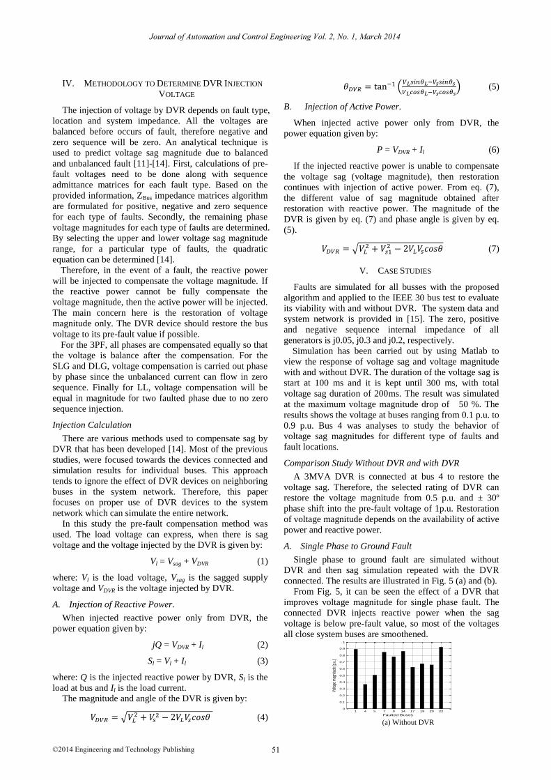
A. Single Phase to Ground Fault
Single phase to ground fault are simulated without
DVR and then sag simulation repeated with the DVR
connected. The results are illustrated in Fig. 5 (a) and (b).
From Fig. 5, it can be seen the effect of a DVR that
improves voltage magnitude for single phase fault. The
connected DVR injects reactive power when the sag
voltage is below pre-fault value, so most of the voltages
all close system buses are smoothened.
(a) Without DVR
1 4 5 7 9 14 17 19 20 220
0.1
0.2
0.3
0.4
0.5
0.6
0.7
0.8
0.9
1
Faulted Buses
Volta
ge m
agni
tude
(p.u
.)
Journal of Automation and Control Engineering Vol. 2, No. 1, March 2014
51©2014 Engineering and Technology Publishing
(b) With DVR
Figure 5. Single phase sag magnitude.
B. Three Phase to Ground Fault
Three phases to ground fault are simulated without
DVR and then sag simulation repeated with the DVR
connected. The results are illustrated in Fig. 6 (a) and (b).
(a) Without DVR
(b) With DVR
Figure 6. Three phase sag magnitude.
The effect of connecting with and without DVR can be
clearly seen from Fig. 6. DVR improves voltage
magnitude for all other buses and not only bus 4.
C. Double Phase to Ground Fault
Double phase to ground fault are simulated without
DVR and then sag simulation repeated with the DVR
connected. The results are illustrated in Fig. 7 (a) and (b).
From Fig. 7, it can be seen the effect of a DVR that
improves voltage magnitude for double phase ground
fault. The connected DVR injects reactive power when
the sag voltage is below pre-fault value, so most of the
voltages all close system buses are smoothened.
(a) Without DVR
(b) With DVR
Figure 7. Double phase sag magnitude.
D. Line-to-line Fault
Line-to-line fault are simulated without DVR and then
sag simulation repeated with the DVR connected. The
results are illustrated in Fig. 8 (a) and (b).
(a) Without DVR
(b) With DVR
Figure 8. Line-to-line sag magnitude.
From Fig. 8, it can be seen the effect of a DVR that
improves voltage magnitude for line-to-line fault. The
connected DVR injects reactive power when the sag
voltage is below pre-fault value at, so most of the
voltages all close system buses are smoothened.
It can be seen that the overall improvement of bus
voltage magnitude ranging from 0% to 35% depending
on distance of the bus from DVR and rating of DVR.
From the simulation results it can conclude that DVR can
restores the voltage magnitude in the system network and
all so the whole network.The amount of injection of
active power and reactive power is depends on the
severity of the fault in system network.
The cost of DVR depends on the power rating, if less
real power, than the cost of DVR will be cheaper but less
effective than the bigger real power used. Therefore total
cost of the solution and voltage profile requirements at
the bus and whole network should be taken into account
when deciding DVR.
VI. CONCLUSION
In this paper, the operation and capability of DVR used
in system network is introduced. Detailed components
and working principles of DVR were explained. Methods
1 4 5 7 9 14 17 19 20 220
0.1
0.2
0.3
0.4
0.5
0.6
0.7
0.8
0.9
1
Faulted Buses
Vol
tage
mag
nitu
de (
p.u.
)
1 4 5 7 9 14 17 19 20 220
0.1
0.2
0.3
0.4
0.5
0.6
0.7
0.8
0.9
1
Faulted Buses
Vol
tage
mag
nitu
de (
p.u.
)
1 4 5 7 9 14 17 19 20 220
0.1
0.2
0.3
0.4
0.5
0.6
0.7
0.8
0.9
1
Faulted Buses
Vol
tage
mag
nitu
de (p
.u.)
1 4 5 7 9 14 17 19 20 220
0.1
0.2
0.3
0.4
0.5
0.6
0.7
0.8
0.9
1
Faulted Buses
Volta
ge m
agni
tude
(p.u
.)
1 4 5 7 9 14 17 19 20 220
0.1
0.2
0.3
0.4
0.5
0.6
0.7
0.8
0.9
1
Faulted Buses
Volta
ge m
agnit
ude
(p.u
.)
1 4 5 7 9 14 17 19 20 220
0.1
0.2
0.3
0.4
0.5
0.6
0.7
0.8
0.9
1
Faulted Buses
Vol
tage
mag
nitu
de (p
.u.)
1 4 5 7 9 14 17 19 20 220
0.1
0.2
0.3
0.4
0.5
0.6
0.7
0.8
0.9
1
Faulted Buses
Vol
tage
mag
nitu
de (p
.u.)
Journal of Automation and Control Engineering Vol. 2, No. 1, March 2014
52©2014 Engineering and Technology Publishing
of control strategies for voltage compensation for three
different types of control systems were illustrated in
detail. Calculations of DVR were derived in order to
minimize the input of real power. Based on the
calculation, the magnitude of injection of voltage and
current (real power and reactive power) by DVR can be
obtained. The capability of the simulation with and
without DVR, were demonstrated on 30-bus generic
distribution system. The efficiency of the mitigation
devices can be seen from the results obtained with and
without DVR.
REFERENCES
[1] M. H. J. Bollen, “Understanding power quality problems: Voltage sags and interruptions,” ser. Power Engineering, Piscataway, NJ:
IEEE Press 2000.
[2] R. C. Dugan, M. F. McGranaghan, and H. W. Beaty, Electrical Power System Quality, New York: McGraw-Hill, 1996.M. T.
[3] M. T. Aung, J. V. Milanovic, and C. P. Gupta, “Propagation of
assymmetrical sags and the innfluence of boundary crossing lines on voltage sag prediction,” IEEE Trans. Power Del., vol. 19, no. 4,
pp. 1819-1827, Oct 2004.
[4] I. Hunter, “Power quality issues: A distribution company perpective,” Power Engineering Journal, vol. 15, pp. 75-80, 2001.
[5] J. V. Milanovic and C. P. Gupta, “Probabilistic of financial losses
due to interruptions and voltage sags–Part I: The methodology,” IEEE Trans Power Del., vol. 21, no. 2, pp. 918-924, 2006.
[6] J. V. Milanovic and C. P. Gupta, “Probabilistic of financial losses
due to interruptions and voltage sags–Part II: Practical implementation,” IEEE Trans Power Del., vol. 21, no. 2, pp. 925-
932, 2006.
[7] A. Ghosh and Gerard, “Power quality enhancement using custom power devices,” Kluwer Power Electronics and Power System
Series, 2002.
[8] A. Ghosh and G. Ledwich, “Compensation of distribution system voltage using DVR,” IEEE Trans. on Power Del., vol. 17, pp.
1030-1036, 2002. [9] D. V. Hertem, M. Didden, J. Driesen, and R. Belmans, “Choosing
the correct mitigation method against voltage dips and interruption:
A customer-based approach,” IEEE Trans. on Power Delivery, vol. 22, no. 1, pp. 331-391, Jan 2007.
[10] S. S. Choi, J. D. Li and D. M. Vilathgamuwa, “Dynamic voltage
restorating with minimum energy injection,” IEEE Trans. on Power Sys., vol. 15, pp. 51-57, Feb 2000.
[11] M. R. Qader, M. H. J. Bollen, and R. N. Allan, “Stochastic
prediction of voltage sags in a large transmission system,” IEEE Trans. Industrial Applications, vol. 35, no. 1, pp. 152–162, Jan
/Feb 1999.
[12] E. E. Juarez and A. Hernandez, “An analytical approach for stochastic assessment of balance and unbalanced voltage sags in
large system,” IEEE Trans. Power Del., vol. 21, no. 3, pp. 1493-
1500, July 2006. [13] Y. S. Lim and G. Strbac, “Analytical approach to probabilistic
prediction of voltage sags ontransmission networks,” Inst. Elect
Eng., Gen., Transm. Distrib., vol. 149, no. 1, pp. 7-14, Jan 2002. [14] R. Jeyagopi and V. K. Ramachandaramurthy, “Stochastic
assessment of voltage sags for balanced and unbalanced faults,”
IREE, vol. 6, no. 5, Oct 2011. [15] IEEE Reliability Test System, IEEE Trans. Power Syst., vol. 14,
no. 3, pp. 1010–1020, Aug 1999.
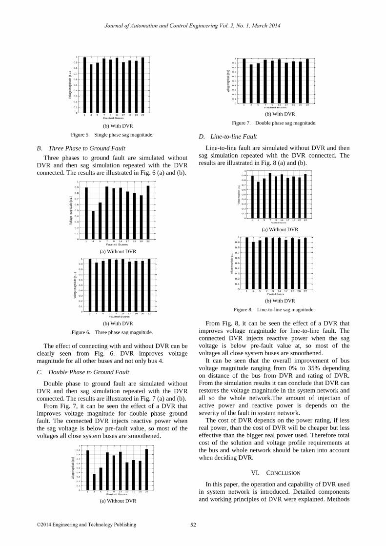
Jeya Gopi received his BEng degree in
Electronic and Electrical Engineering from
Robert Gordan University, UK and MSc degree in Mechatronic from De Montfort University,
UK.He is currently Senior lecturer at INTI
International University, Nilai, Malaysia. His research interest includes power quality analysis
and power systems studies.
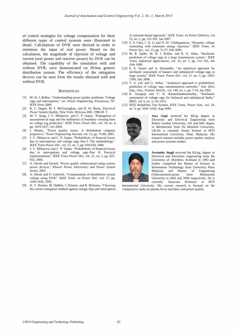
Arwinder Singh received his B.Eng. degree in
Electrical and Electronic engineering from the University of Aberdeen, Scotland in 1993 and
further completed his Master of Science in
Information Technology from University Putra Malaysia and Master of Engineering
(Telecommunication) from Multimedia University in 2002 and 2006 respectively. He is
currently Associate Professor at INTI
International University. His current research is focused on the comparative study on plasma focus machines and power quality.
Journal of Automation and Control Engineering Vol. 2, No. 1, March 2014
53©2014 Engineering and Technology Publishing