Embed Size (px)
Citation preview

2
Index1. GENERAL INFORMATION 41.1 PRODUCER 41.2 ASSISTANCE CENTERS 41.3 CERTIFICATION 41.4 WARRANTY 41.5 PRE-ARRANGEMENTS CHARGED TO
THE CUSTOMER 41.6 HANDBOOK STRUCTURE 41.6.1 Object and contents 41.6.2 Utilizers 41.6.3 Preservation 41.6.4 Symbols utilized 52. MACHINE DESCRIPTION 62.1 WORKING PRINCIPLE 62.2 MAIN COMPONENTS 62.3 MACHINE STRUCTURE 62.4 DIMENSIONS 62.5 SURROUNDING CONDITIONS 62.6 LIGHTING 62.7 VIBRATIONS 62.8 NOISE EMISSIONS 62.9 TECHNICAL DATA 72.10 STANDARD EQUIPMENT 72.10.1 Standard accessories 72.10.2 Upgrading and implementing of mechanical
parts 72.10.3.Customized optional accessories 72.11 ELECTROMAGNETIC AMBIENT 73. SAFETY 83.1 GENERAL WARNINGS 83.2 SCHEDULED USE 83.3 INADVISABLE USE 83.4 DANGEROUS AREAS 83.5 PROTECTION DEVICES 83.6 STOP FUNCTIONS 83.7 SAFE WORKING PROCEDURES 83.8 RESIDUAL RISKS 93.9 PLATES 94. INSTALLATION 94.1 SHIPPING AND HANDLING 94.2 STORAGE 94.3 PRELIMINARY ARRANGEMENTS 104.4 UNPACKING 104.5 MACHINE POSITIONING 104.6 CONNECTIONS 104.6.1 Pneumatic connection 104.6.2 Electric connection 104.6.3 Collegamento elettrico della tastiera di
controllo 114.7 PRELIMINARY CONTROLS 124.8 MACHINE ARRANGEMENT 12
4.8.1 V-Nails magazine loadiing 124.8.2. V-nail guide head replacement to change V-nails
size 124.9 ADJUSTMENTS 134.9.1 Adjustments for v-nails positioning 134.9.2 VERTICAL CLAMP ADJUSTMENT 134.9.2.A Vertical clamp position adjustment 134.9.2.B Vertical clamp height adjustment 134.9.3 Frontal clamp adjustment 144.9.4 FENCE ADJUSTMENT 144.9.5 Working pressure adjustment 144.9.6. Protective shield adjustment 154.10 CHECKING OPERATIONS TO BE EF-
FECTED BEFORE WORKING START 155 FUNCTIONING 165.1 OPERATORS 165.2 CONTROL PANEL 165.3 KEYBOARD CODE/COLORS OF ELEC-
TRONIC CONTROL DEVICE 175.4 Mode of operation 185.4.1 Manual functions menu 185.4.2 Jog menu 185.4.3 Input test menu 185.4.4 Output test menu 185.4.5 Machine zero point (homing) 195.4.6 Editing menu 195.4.7 Rename 195.4.8 Copy 195.4.9 Delete 195.4.10 Search 195.4.11 Creation of new programs 195.4.12 Execution menu 215.4.13 Working speed modification 225.4.14 Enabling access code protected services 225.5 FRAMES PRODUCTION AND V-NAILS
CONSUMPTION 235.6 TIPS FOR PERFECT JUNCTIONS 235.7 MACHINE STOP 245.8 PUTTING OUT OF SERVICE 246. PROGRAMMING 256.1 CREATION OF A PROGRAM 256.1.A. Auto-learning mode 256.1.B Inputting mode 257. EXECUTION OF THE PROGRAM 267.1 EXECUTION OF JUST DIGITED
PROGRAM 267.2 EXECUTION OF A PROGRAM PREVI-
OUSLY MEMORIZED 267.3 MACHINE ADJUSTMENT 268. MAINTENANCE 278.1 STATE OF MAINTENANCE 278.2 MACHINE ISOLATION 278.3 SPECIAL CAUTIONS 278.4 CLEANING 278.5 LUBRICATION 278.6 ORDINARY MAINTENANCE 278.7 EXTRAORDINARY MAINTENANCE 28
3
9. DIAGNOSTIC 299.1 SAFETY WARNINGS 299.2 BREAKDOWN SEARCH 299.3 REQUEST OF ASSISTANCE 3010. SPARE PARTS 3110.1 SPARE PARTS LIST 3110.2 SPARE PARTS ORDERING 3111. DEMOLITION 3111.1 DEMOLITION 3112. ATTACHMENTS 3112.1 DECLARATIONS 3112.2 SCHEMES 31
4
1. GENERAL INFORMATION
1.1 PRODUCERThe rm Alfamacchine-AMP can boast more than 10years of experience in the construction of WoodworkingMachines. It is the acquired technological know-how,developed during years of research in strict touch withmanufacturing d ep artmen t s and in te rnat ionalcommercialization. We o er the best warranty that anyonecan grant to its customers.
TEL 800-322-4204 FAX 800-426-7019
1.2 ASSISTANCE CENTERSAMP is represented throughout North America.Contact us directly to nd your nearest distributor.For eve ry need regard ing Use , Main tenance orRequest of Spare Parts, the Customer is requested tocall the authorized service centers or directly toAMP, sp ecifying the machine ’s iden t i cat ion dataimpressed on the plate.
1.3 CERTIFICATIONThe machine is produced in conformity to the pertinentEuropean Community Norms in force at the moment of itsintroduction on the market.
1.5 PRE-ARRANGEMENTS CHARGED TOTHE CUSTOMER
It is the customer’s d u ty, on t imes ag reed withthe p rod uce r, to execu te what is ind icated inour d ocumentat ion (see the at t achment 10.3-B).Th ings normally charged to the customer:
Premises p red isp osit ion , includ ed b uild ingworksMach ine p ower sup p ly, ob se rving the curren tnorms of Coun t ry where the mach ine isinsta lled (see at the p arag rap h 4.6.2)Pneumat ic sup p ly of comp ressed air (see a tthe p arag rap h 4.6.1)
1.4 WARRANTYAMP’s p rod uct s are b u ilt to have a longlife and are te sted one b y one .If, in sp ite of th is,if any d amages would occuror malfunct ion ing , the rep lacemen t of d e fect ivep art s is warran ted (coun t ing from the d atewrit t en on the d e live ry b ill) fo r a p e riod of:* 24 months for mechanical components* 12 months for pneumatic partThe d rive r b lad e is t e sted for ab out 1.000.000working cycles.The Warran ty d oes not includ e the send ing oft echn ical st a .The repair will be performed at AMP and thefre igh t of sh ip men t will b e en t ire ly charged tothe Customer.
The warran ty d oes not cove r the d amages causedb y an inap p rop ria te use of the mach ine or notcorre sp ond ing to the inst ruct ions d escrib ed inth is hand b ook.The warran ty d ecays in case of unau thorizedmod i cat ions or b ecause of accid en tal d amag esor t amp ering p erformed b y unq uali ed p e rsonne l.The warran ty a lso d ecays if you use V-nailsd i e ren t from the orig inal AMP’s ones.To take ad van tage of warran ty se rvices it isnecessary, at the moment you receive your machineto comp le te ly ll ou t the warran ty card andsend b ack as soon as p ossib le to AMP.The warran ty will b e valid aft e r it is rece ived& recorded at AMP.
1.6 HANDBOOK STRUCTUREThe customer must p ay ext reme at t en t ion to theind icat ions rep orted in th is hand b ook, b ecausethe p rop e r Pre -Arrangement , Insta lla t ion andUse of the Mach ine , const itu te the b asis o f acorrect customer-d ist rib u tor re la t ionsh ip .1.6.1 Object and contentsThe hand b ook goal is to p rovid e to the customerall necessary in format ion so that , b esid es thep rop er use of the mach ine , He would b e ab le torun it in comp le te au tonomy and safe ty. Thehand b ook con tains in format ion conce rn ing thetechn ical asp ect s, mach ine working andstand st ill, main tenance , sp are p art s and safe ty.Before making any op e rat ion on the mach ine , t heq uali ed techn icians and op erators mustcare fu lly read th is hand b ook. In case of d oub tab out correct in te rp re ta t ion of theinst ruct ions, ask yur local d ist rib u tor orAMP to exp lain it to you .1.6.2 UtilizersThis handbook is made both for operators and techniciansauthorized to the machine maintenance.The operators cannot execute operations reserved to themaintainers or to the quali ed technicians.The producer does not answer of damages derived from not-observance of this prohibition1.6.3 PreservationThe instruction handbook must be kept very closed to themachine, into a special container protected from liquids andwhatever could compromise its legibility
5
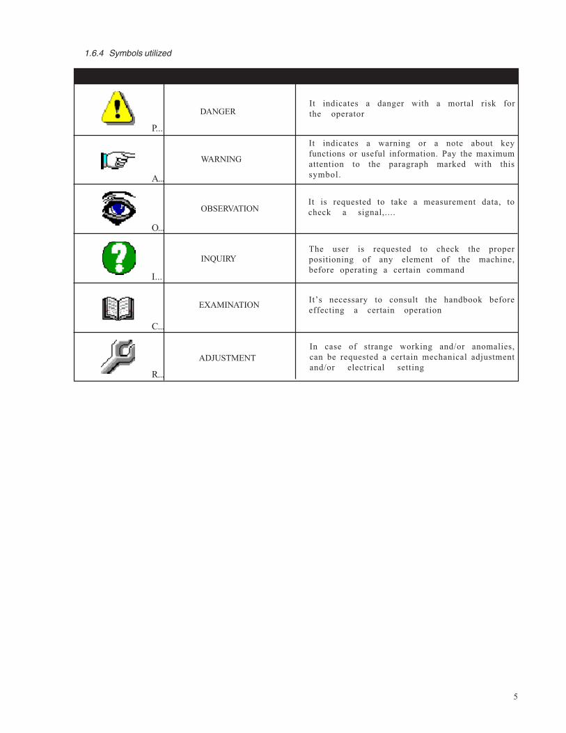
1.6.4 Symbols utilized
P...
A...
O...
I...
C...
R...
WARNING
OBSERVATION
INQUIRY
EXAMINATION
ADJUSTMENT
It indicates a danger with a mortal risk forthe operator
It indicates a warning or a note about keyfunctions or useful information. Pay the maximumattention to the paragraph marked with thissymbol.
It is requested to take a measurement data, tocheck a signal,....
The user is requested to check the properpositioning of any element of the machine,before operating a certain command
It’s necessary to consult the handbook beforeeffecting a certain operation
In case of strange working and/or anomalies,can be requested a certain mechanical adjustmentand/or electrical setting
DANGER
6
2. MACHINE DESCRIPTION2.1 WORKING PRINCIPLEThe frame assembling machine Mitre-Mite VN 4Memory Program has been realized for the massproduction of medium or large sized frames.The machine is controlled by an electronicsystem able to execute very quickly the differentworking cycles.You can store in the machine’s memory 1.400different programs corresponding to severaltypes and sizes of frames.The machine can work only semi-automaticallycontrolled by a program input by the operator.The frame assembling machine Mitre-Mite VN 4Memory Program can use special V-nails with“pulling power” to pull the joints tightlyt o g e t h e r .
2.2 MAIN COMPONENTSThe main components constituting the machinea r e :• Frontal clamping device to have a perfect
j o i n t .• Floor stand with Filter/regulator/lubricator• Double Hydralic hold down• Double & triple mechanical hold downs• Pneumatic opening of V-nails magazine for a
very quick reloading• Nail heads sizes 7, 10 and 15 mm.
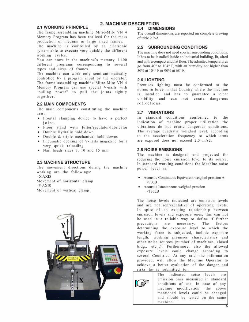
2.3 MACHINE STRUCTUREThe movement directions during the machineworking are the followings:- X AXISMovement of horizontal clamp- Y AXISMovement of vertical clamp
2.4 DIMENSIONSThe overall dimensions are reported on complete drawingof table 2.9-A
2.5 SURROUNDING CONDITIONSThe machine does not need special surrounding conditions.It has to be installed inside an industrial building, lit, airedand with a compact and flat floor. The admitted temperaturesgo from 40° to 104° F, with an humidity not higher than50% at 104° F or 90% at 68° F.
2.6 LIGHTINGPremises lighting must be conformed to thenorms in force in that Country where the machineis installed and has to guarantee a clearvisibility and can not create dangerousr e f l e c t i o n s .
2.7 VIBRATIONSIn standard conditions conformed to theindication of machine proper utilization thevibrations do not create dangerous conditions.The average quadratic weighed level, accordingto the acceleration frequency to which armsare exposed does not exceed 2,5 m/s2.
The indicated noise levels areemission ones measured in standardconditions of use. In case of anymachine modification, the abovementioned levels could be changedand should be tested on the samemachine.
2.8 NOISE EMISSIONSThe machine is designed and projected forreducing the noise emission level to its source.In standard working conditions the Machine noisepower level is:
• Acoustic Continuous Equivalent weighed pression A<70dB
• Acoustic Istantaneous weighed pression<130dB
The noise levels indicated are emission levelsand are not representative of operating levels.In spite of an existing relationship betweenemission levels and exposure ones, this can notbe used in a reliable way to define if furtherprecautions are necessary. The factorsdetermining the exposure level to which theworking force is subjected, include exposurelength, working premises characteristics andother noise sources (number of machines, closedbldg., etc...). Furthermore, also the allowedexposure levels could change according toseveral Countries. At any rate, the informationprovided, will allow the Machine Operator toachieve a better evaluation of the danger andrisks he is submitted to.
7
2.10 STANDARD EQUIPMENTThe equipment listed below are the standardo n e s :2.10.1 Standard accessoriesOnce you have removed the packing, please checkthe presence of following accessories:- N.1 nail head mm. 7- N.1 nail head mm.10- N.1 nail head mm.15- N.1 L shaped pressure pad- N.1 Allen Wrench 5 mm. for V-nails head replacement- N. 4 adjustable feet.- N.1 pressure gauge- N.1 fast clutch fitting- N.1 Brass rod magnet to remove V-nails- N.1 double hydraulic hold down- N.1 double & triple mechanical hold down
2.10.3.Customized optional accessoriesThanks to its versatility this machine can be‘custom-made’ to meet our users’ requirements,by using additional accessories that can makeframe assembling easier: e.g. special fencesfor peculiar moulding shapes, special clampsto ensure the mouldings are locked properlyduring V-nail firing, and so on. You can haveyour local machine shop make these for you.
2.10.2 Upgrading and implementing mechanical partsThe machine has been designed and developedbased on modular standards, therefore theexisting equipment can be further upgraded withadditional accessories that will not alter itsbasic structure.Technical upgrades on the machine model, ifany, will be such that they can be installed atany time without requiring any substantialmodifications to the machine structure.
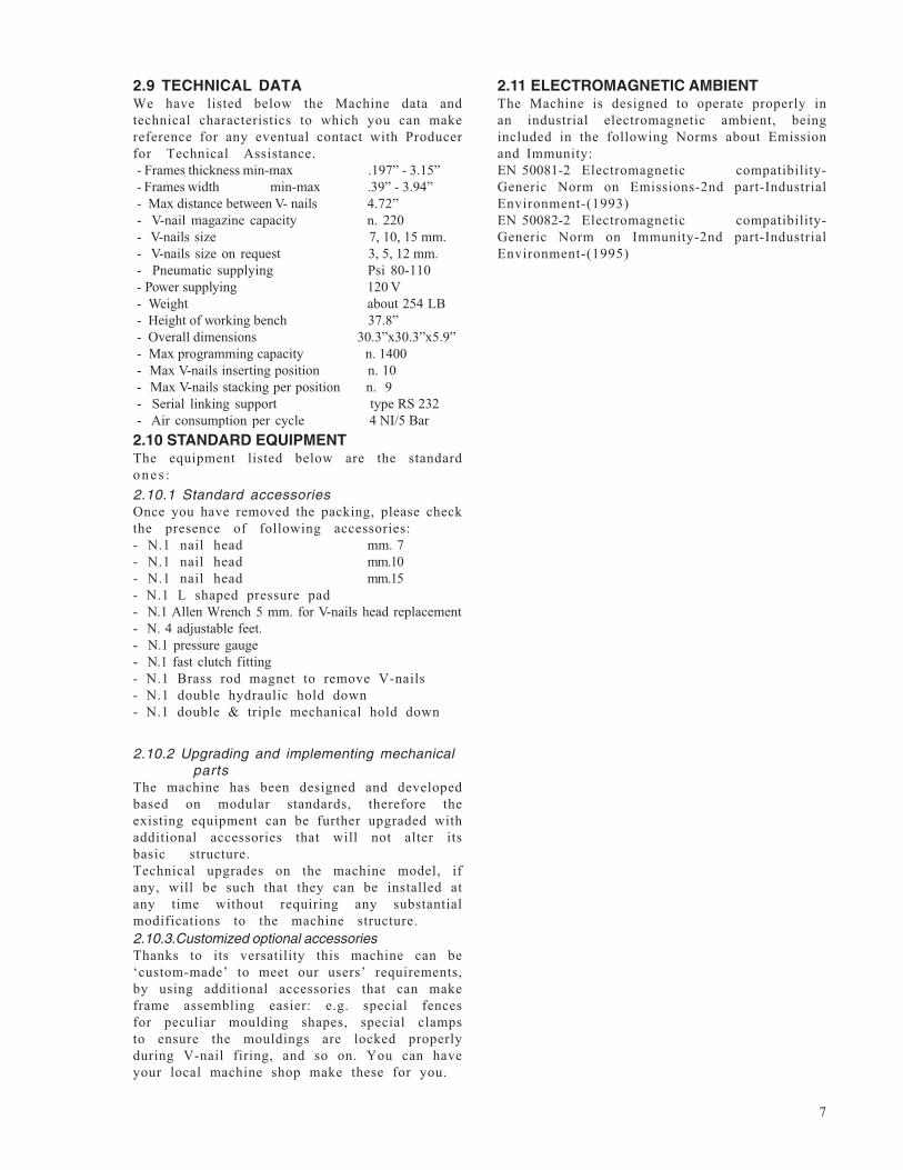
2.9 TECHNICAL DATAWe have listed below the Machine data andtechnical characteristics to which you can makereference for any eventual contact with Producerfor Technical Assistance.- Frames thickness min-max .197” - 3.15”- Frames width min-max .39” - 3.94”- Max distance between V- nails 4.72”- V-nail magazine capacity n. 220- V-nails size 7, 10, 15 mm.- V-nails size on request 3, 5, 12 mm.- Pneumatic supplying Psi 80-110- Power supplying 120 V- Weight about 254 LB- Height of working bench 37.8”- Overall dimensions 30.3”x30.3”x5.9”- Max programming capacity n. 1400- Max V-nails inserting position n. 10- Max V-nails stacking per position n. 9- Serial linking support type RS 232- Air consumption per cycle 4 NI/5 Bar
2.11 ELECTROMAGNETIC AMBIENTThe Machine is designed to operate properly inan industrial electromagnetic ambient, beingincluded in the following Norms about Emissionand Immunity:EN 50081-2 Electromagnetic compatibility-Generic Norm on Emissions-2nd part-IndustrialEnvironment-(1993)EN 50082-2 Electromagnetic compatibility-Generic Norm on Immunity-2nd part-IndustrialEnvironment-(1995)
8
3.SAFETY
3.1 GENERAL WARNINGSThe operator must read paying the maximumattention to the information written in thisHandbook, expressively about proper precautionsfor Safety listed in this chapter.It is indispensable for the operator to followthe warnings list here below:• Keep the machine & it’s working area clean
& ordered• Provide appropriate containers to stock
moulding to be used.• Use the Machine only in perfect psycho
physical condition• Wear an adequate clothing to avoid obstacles
and/or dangerous entangles to/from themachine
• Wear the individual protection gearsprescribed by this instructions handbook
• Do not remove or alter the warning platesand adhesive signs
• Do not remove or elude the Machine SafetySystems
• Keep the fingers away from the working area• Disconnect the air pressure and power supply
during any maintenance intervention• Keep the feet separated from the pedal during
Machine repair
3.3 INADVISABLE USEThe machine can not be used for:• For uses different from those listed in 3.2
paragraph• In an explosive or aggressive atmosphere,
where there is a high density of dust oroily substances suspended in the air
• In flammable atmosphere• Outside in all weather severity• With disconnected electromagnetic
i n t e r b l o c k s• With electric bridges and/or mechanical
instruments leaving out machine parts orf u n c t i o n s
• For working materials not suitable withmachine characteristics
3.2 SCHEDULED USEThe Machine is designed and built to executejunctions of frames.The machine is projected for semi-automaticoperation (under operator control).
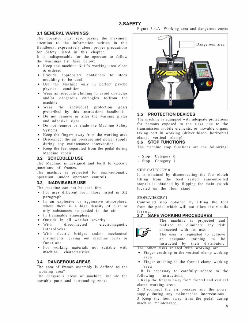
3.4 DANGEROUS AREASThe area of frames assembly is defined as the“working area”The dangerous areas of machine, include themovable parts and surrounding zones
3.5 PROTECTION DEVICESThe machine is equipped with adequate protectionsfor persons exposed to the risks due to thetransmission mobile elements, or movable organstaking part in working (driver blade, horizontalclamp, vertical clamp).
3.7 SAFE WORKING PROCEDURES
The other risks related with working are:• Finger crushing in the vertical clamp working
a r e a• Finger crushing in the frontal clamp working
a r e a It is necessary to carefully adhere to thefollowing instructions:1 Keep the fingers away from frontal and verticalclamp working areas2 Disconnect the air pressure and the powersupply during any maintenance interventions3 Keep the foot away from the pedal duringmachine maintenance.
3.6 STOP FUNCTIONSThe machine stop functions are the following:
- Stop Category 0.- Stop Category 1.
STOP CATEGORY 0It is obtained by disconnecting the fast clutchfitting from the feed system (uncontrolledstop).It is obtained by flipping the main switchlocated on the floor stand.
STOP CATEGORY 1Controlled stop obtained by lifting the footfrom the pedal which will not allow the v-nailsf i r i n g .
The machine is projected andrealized to eliminate any riskconnected with its use.The user is requested to achievean adequate training to beinstructed by their distributor.
Dangerous area
Figure 3.4.A- Working area and dangerous zones
9
3.8 RESIDUAL RISKSDuring the normal working cycle and whileperforming maintenance, the operators areexposed to several residual risks that, becauseof operations own nature, can not be totallye l i m i n a t e d .• Risk of finger crushing due to the presence
of vertical and frontal clamping• Risk due the presence of electricity in the
machine3.9 PLATESThe warning plates carrying out safety functionscan not be removed, covered or damaged.To view the plates or adhesive signs location,consult the Fig.10.2-D
Table 3.9 A- Types of plates
Plate concerning machine characteristics
Adhesive sign concerning the finger dangerzone
Adhesive sign concerning the finger dangerzone
Adhesive sign concerning the behaviour to bekept in the working area
4. INSTALLATION
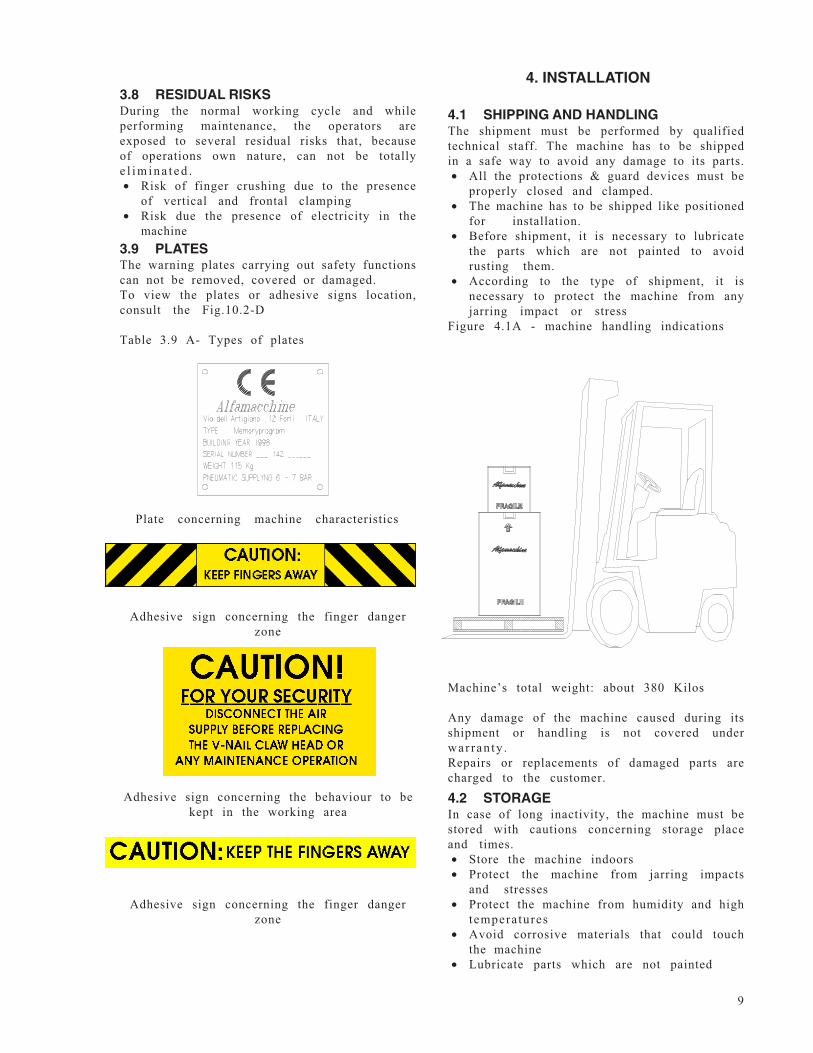
4.1 SHIPPING AND HANDLINGThe shipment must be performed by qualifiedtechnical staff. The machine has to be shippedin a safe way to avoid any damage to its parts.• All the protections & guard devices must be
properly closed and clamped.• The machine has to be shipped like positioned
for installation.• Before shipment, it is necessary to lubricate
the parts which are not painted to avoidrusting them.
• According to the type of shipment, it isnecessary to protect the machine from anyjarring impact or stress
Figure 4.1A - machine handling indications
Machine’s total weight: about 380 Kilos
Any damage of the machine caused during itsshipment or handling is not covered underwar ran ty .Repairs or replacements of damaged parts arecharged to the customer.
4.2 STORAGEIn case of long inactivity, the machine must bestored with cautions concerning storage placeand times.• Store the machine indoors• Protect the machine from jarring impacts
and stresses• Protect the machine from humidity and high
temperatures• Avoid corrosive materials that could touch
the machine• Lubricate parts which are not painted
10
4.6 CONNECTIONSTo avoid any p rob lems while st art ing up themach ine , it is suggested to fo llow what isd escrib ed b e low.
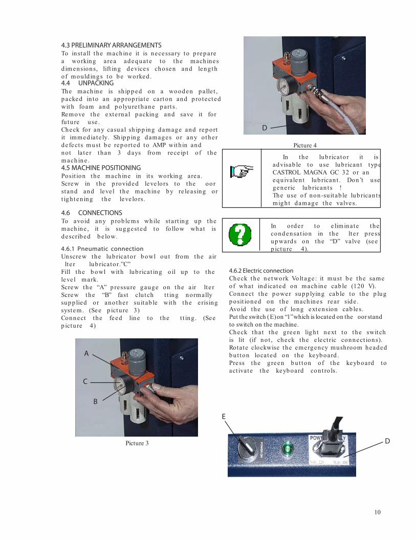
4.6.1 Pneumatic connectionUnscrew the lub ricator b owl out from the air
lt e r lub ricator.”C”Fill the b owl with lub ricat ing o il up to theleve l mark.Screw the “A” p ressure gauge on the air lt e rScrew the “B” fast clu tch t t ing normallysup p lied or ano the r su it ab le with the e risingsystem. (See p ictu re 3)Connect the feed line to the t t ing . (Seep ictu re 4)
In the lub ricato r it isad visab le to use lub rican t typ eCASTROL MAGNA GC 32 or aneq uivalen t lub rican t . Don ’t usegene ric lub rican t s !The use of non-su it ab le lub rican t smigh t d amage the valves.
4.6.2 Electric connectionCheck the ne twork Voltage : it must b e the sameof what ind icated on mach ine cab le (120 V).Connect the p ower sup p lying cab le to the p lugp osit ioned on the mach ines rear sid e .Avoid the use of long extension cab le s.Put the switch ( E ) on “1”which is located on the oor standto switch on the machine.Check that the g reen ligh t next to the switchis lit (if no t , check the e lect ric connect ions).Rotate clockwise the emergency mushroom headedb ut ton located on the keyb oard .Press the green b ut ton of the keyb oard toact ivate the keyb oard con t ro ls.
4.3 PRELIMINARY ARRANGEMENTSTo install the mach ine it is necessary to p rep area working area ad eq uate to the mach inesd imensions, lift ing d evices chosen and leng thof mould ings to b e worked .4.4 UNPACKINGThe mach ine is sh ip p ed on a wood en p alle t ,p acked in to an ap p rop ria te carton and p ro tectedwith foam and p olyure thane p art s.Remove the exte rnal p acking and save it forfu tu re use .Check for any casual sh ip p ing d amage and rep ortit immed iate ly. Sh ip p ing d amages or any othe rd e fect s must b e rep orted to AMP with in andnot la te r than 3 d ays from rece ip t of them ach in e .4.5 MACHINE POSITIONINGPosit ion the mach ine in it s working area.Screw in the p rovid ed leve lors to the oorstand and leve l the mach ine b y re leasing ort igh ten ing the leve lo rs.
A
B
C
Picture 3
D
Picture 4
In ord e r to e liminate thecond ensat ion in the lt e r p ressup ward s on the “D” valve (seep ictu re 4).
D
E
11
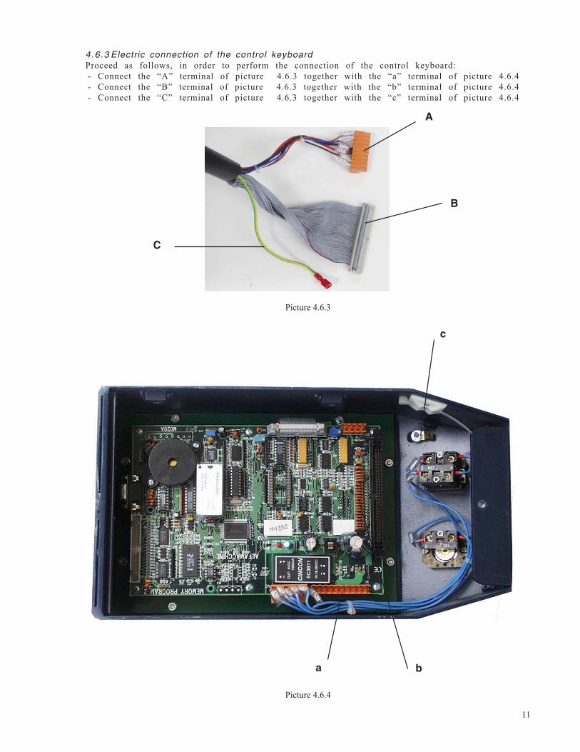
4.6.3 Electric connection of the control keyboardProceed as follows, in order to perform the connection of the control keyboard:- Connect the “A” terminal of picture 4.6.3 together with the “a” terminal of picture 4.6.4- Connect the “B” terminal of picture 4.6.3 together with the “b” terminal of picture 4.6.4- Connect the “C” terminal of picture 4.6.3 together with the “c” terminal of picture 4.6.4
Picture 4.6.3
Picture 4.6.4
c
ba
A
B
C
12
4.8.2. V-nail guide head replacement tochange V-nails size
The V-nail guide head must be changed each timeyou use V-nails of different sizes.Proceed as follows to change it:
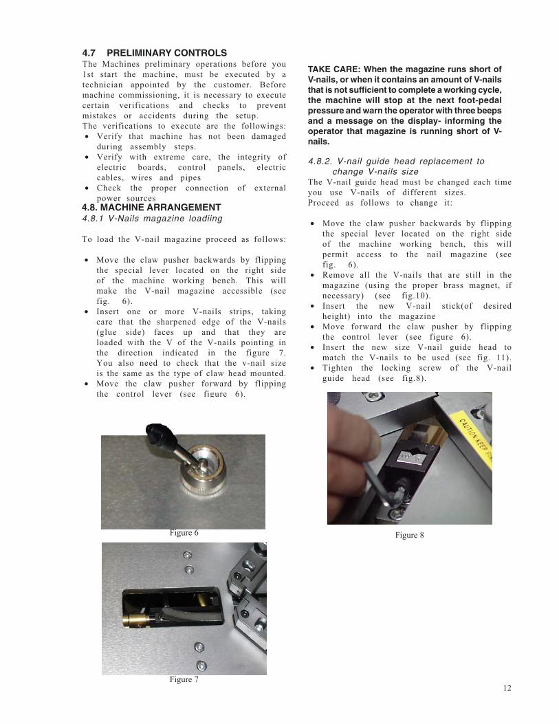
• Move the claw pusher backwards by flippingthe special lever located on the right sideof the machine working bench, this willpermit access to the nail magazine (seefig. 6).
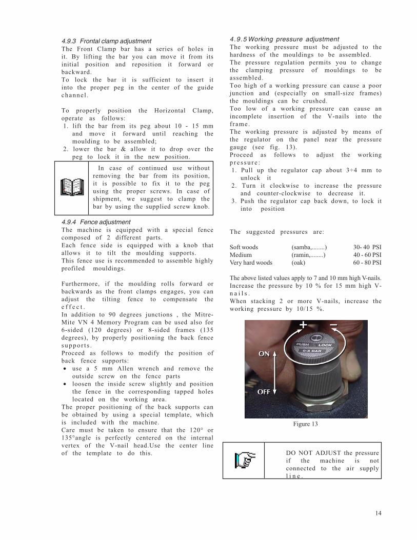
• Remove all the V-nails that are still in themagazine (using the proper brass magnet, ifnecessary) (see fig.10).
• Insert the new V-nail stick(of desiredheight) into the magazine
• Move forward the claw pusher by flippingthe control lever (see figure 6).
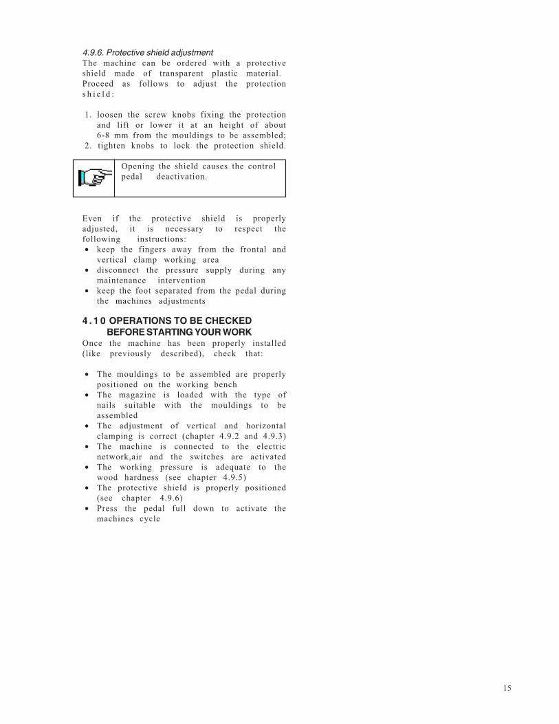
• Insert the new size V-nail guide head tomatch the V-nails to be used (see fig. 11).
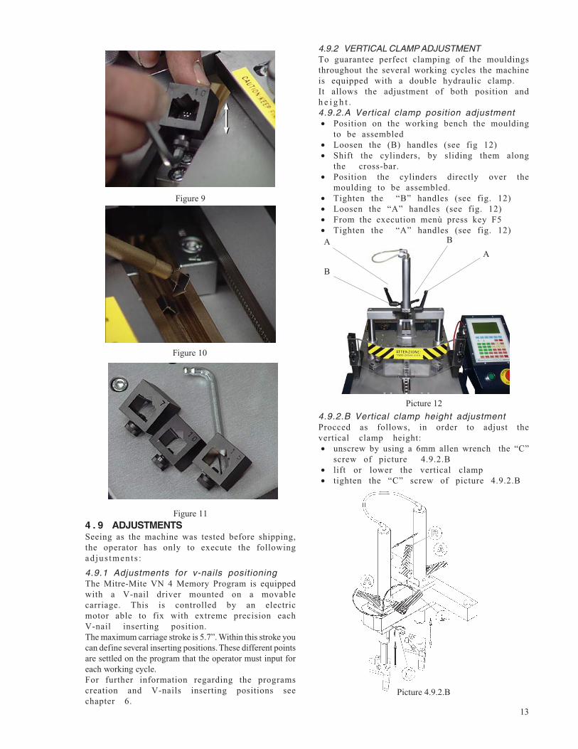
• Tighten the locking screw of the V-nailguide head (see fig.8).
4.8. MACHINE ARRANGEMENT4.8.1 V-Nails magazine loadiing
To load the V-nail magazine proceed as follows:
• Move the claw pusher backwards by flippingthe special lever located on the right sideof the machine working bench. This willmake the V-nail magazine accessible (seefig. 6).
• Insert one or more V-nails strips, takingcare that the sharpened edge of the V-nails(glue side) faces up and that they areloaded with the V of the V-nails pointing inthe direction indicated in the figure 7.You also need to check that the v-nail sizeis the same as the type of claw head mounted.
• Move the claw pusher forward by flippingthe control lever (see figure 6).
TAKE CARE: When the magazine runs short ofV-nails, or when it contains an amount of V-nailsthat is not sufficient to complete a working cycle,the machine will stop at the next foot-pedalpressure and warn the operator with three beepsand a message on the display- informing theoperator that magazine is running short of V-nails.
Figure 8
Figure 7
Figure 6
4.7 PRELIMINARY CONTROLSThe Machines preliminary operations before you1st start the machine, must be executed by atechnician appointed by the customer. Beforemachine commissioning, it is necessary to executecertain verifications and checks to preventmistakes or accidents during the setup.The verifications to execute are the followings:• Verify that machine has not been damaged
during assembly steps.• Verify with extreme care, the integrity of
electric boards, control panels, electriccables, wires and pipes
• Check the proper connection of externalpower sources
13
Figure 9
Figure 10
Figure 114 . 9 ADJUSTMENTSSeeing as the machine was tested before shipping,the operator has only to execute the followingadjus tments :
4.9.1 Adjustments for v-nails positioningThe Mitre-Mite VN 4 Memory Program is equippedwith a V-nail driver mounted on a movablecarriage. This is controlled by an electricmotor able to fix with extreme precision eachV-nail inserting position.The maximum carriage stroke is 5.7”. Within this stroke youcan define several inserting positions. These different pointsare settled on the program that the operator must input foreach working cycle.For further information regarding the programscreation and V-nails inserting positions seechapter 6.
4.9.2 VERTICAL CLAMP ADJUSTMENTTo guarantee perfect clamping of the mouldingsthroughout the several working cycles the machineis equipped with a double hydraulic clamp.It allows the adjustment of both position andh e i g h t .4.9.2.A Vertical clamp position adjustment• Position on the working bench the moulding
to be assembled• Loosen the (B) handles (see fig 12)• Shift the cylinders, by sliding them along
the cross-bar.• Position the cylinders directly over the
moulding to be assembled.• Tighten the “B” handles (see fig. 12)• Loosen the “A” handles (see fig. 12)• From the execution menù press key F5• Tighten the “A” handles (see fig. 12)
Picture 12
ABA
B
4.9.2.B Vertical clamp height adjustmentProcced as follows, in order to adjust thevertical clamp height:• unscrew by using a 6mm allen wrench the “C”
screw of picture 4.9.2.B• lift or lower the vertical clamp• tighten the “C” screw of picture 4.9.2.B
Picture 4.9.2.B
14
4.9.3 Frontal clamp adjustmentThe Front Clamp bar has a series of holes init. By lifting the bar you can move it from itsinitial position and reposition it forward orbackward.To lock the bar it is sufficient to insert itinto the proper peg in the center of the guidechanne l .
To properly position the Horizontal Clamp,operate as follows:1. lift the bar from its peg about 10 - 15 mm
and move it forward until reaching themoulding to be assembled;
2. lower the bar & allow it to drop over thepeg to lock it in the new position.
4.9.4 Fence adjustmentThe machine is equipped with a special fencecomposed of 2 different parts.Each fence side is equipped with a knob thatallows it to tilt the moulding supports.This fence use is recommended to assemble highlyprofiled mouldings.
Furthermore, if the moulding rolls forward orbackwards as the front clamps engages, you canadjust the tilting fence to compensate thee f f e c t .In addition to 90 degrees junctions , the Mitre-Mite VN 4 Memory Program can be used also for6-sided (120 degrees) or 8-sided frames (135degrees), by properly positioning the back fences u p p o r t s .Proceed as follows to modify the position ofback fence supports:• use a 5 mm Allen wrench and remove the
outside screw on the fence parts• loosen the inside screw slightly and position
the fence in the corresponding tapped holeslocated on the working area.
The proper positioning of the back supports canbe obtained by using a special template, whichis included with the machine.Care must be taken to ensure that the 120° or135°angle is perfectly centered on the internalvertex of the V-nail head.Use the center lineof the template to do this.
4.9.5 Working pressure adjustmentThe working pressure must be adjusted to thehardness of the mouldings to be assembled.The pressure regulation permits you to changethe clamping pressure of mouldings to beassembled.Too high of a working pressure can cause a poorjunction and (especially on small-size frames)the mouldings can be crushed.Too low of a working pressure can cause anincomplete insertion of the V-nails into thef rame.The working pressure is adjusted by means ofthe regulator on the panel near the pressuregauge (see fig. 13).Proceed as follows to adjust the workingp r e s s u r e :1. Pull up the regulator cap about 3÷4 mm to
unlock it2. Turn it clockwise to increase the pressure
and counter-clockwise to decrease it.3. Push the regulator cap back down, to lock it
into position
The suggested pressures are:
Soft woods (samba,........) 30- 40 PSIMedium (ramin,........) 40 - 60 PSIVery hard woods (oak) 60 - 80 PSI
The above listed values apply to 7 and 10 mm high V-nails.Increase the pressure by 10 % for 15 mm high V-n a i l s .When stacking 2 or more V-nails, increase theworking pressure by 10/15 %.
Figure 13
In case of continued use withoutremoving the bar from its position,it is possible to fix it to the pegusing the proper screws. In case ofshipment, we suggest to clamp thebar by using the supplied screw knob.
DO NOT ADJUST the pressureif the machine is notconnected to the air supplyl i n e .
15
4.9.6. Protective shield adjustmentThe machine can be ordered with a protectiveshield made of transparent plastic material.Proceed as follows to adjust the protections h i e l d :
1. loosen the screw knobs fixing the protectionand lift or lower it at an height of about6-8 mm from the mouldings to be assembled;
2. tighten knobs to lock the protection shield.
Even if the protective shield is properlyadjusted, it is necessary to respect thefollowing instructions:• keep the fingers away from the frontal and
vertical clamp working area• disconnect the pressure supply during any
maintenance intervention• keep the foot separated from the pedal during
the machines adjustments
4 . 1 0 OPERATIONS TO BE CHECKEDBEFORE STARTING YOUR WORK
Once the machine has been properly installed(like previously described), check that:
• The mouldings to be assembled are properlypositioned on the working bench
• The magazine is loaded with the type ofnails suitable with the mouldings to beassembled
• The adjustment of vertical and horizontalclamping is correct (chapter 4.9.2 and 4.9.3)
• The machine is connected to the electricnetwork,air and the switches are activated
• The working pressure is adequate to thewood hardness (see chapter 4.9.5)
• The protective shield is properly positioned(see chapter 4.9.6)
• Press the pedal full down to activate themachines cycle
Opening the shield causes the controlpedal deactivation.
16
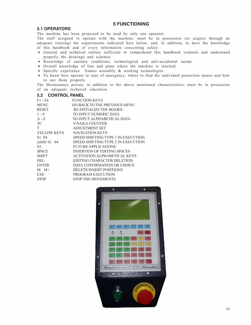
5 FUNCTIONING5.1 OPERATORSThe machine has been projected to be used by only one operator.The staff assigned to operate with the machine, must be in possession (or acquire through anadequate training) the requirements indicated here below, and, in addition, to have the knowledgeof this handbook and of every information concerning safety:• General and technical culture sufficient to comprehend this handbook contents and understand
properly the drawings and schemes• Knowledge of sanitary conditions, technological and anti-accidental norms• Overall knowledge of line and plant where the machine is inserted• Specific experience frames assembly & working technologies• To know how operate in case of emergency, where to find the individual protection means and how
to use them properly.The Maintenance person, in addition to the above mentioned characteristics, must be in possessionof an adequate technical education.5.2 CONTROL PANELF1 - F6 FUNCTION KEYSMENU GO BACK TO THE PREVIOUS MENURESET RE-INITIALIZE THE BOARD1 - 9 TO INPUT NUMERIC DATAA - Z TO INPUT ALPHABETICAL DATATC V-NAILS COUNTERT ADJUSTMENT SETYELLOW KEYS NAVIGATION KEYSS1 S4 SPEED SHIFTING TYPE 1 IN EXECUTION(shift) S1 S4 SPEED SHIFTING TYPE 2 IN EXECUTIONS5 FUTURE APPLICATIONSSPACE INSERTION OF EDITING SPACESSHIFT ACTIVATION ALPHABETICAL KEYSDEL EDITING CHARACTER DELETIONENTER DATA CONFIRMATION OR CHOICEM- M+ DELETE/INSERT POSITIONSEXE PROGRAM EXECUTIONSTOP STOP THE MOVEMENTS
17
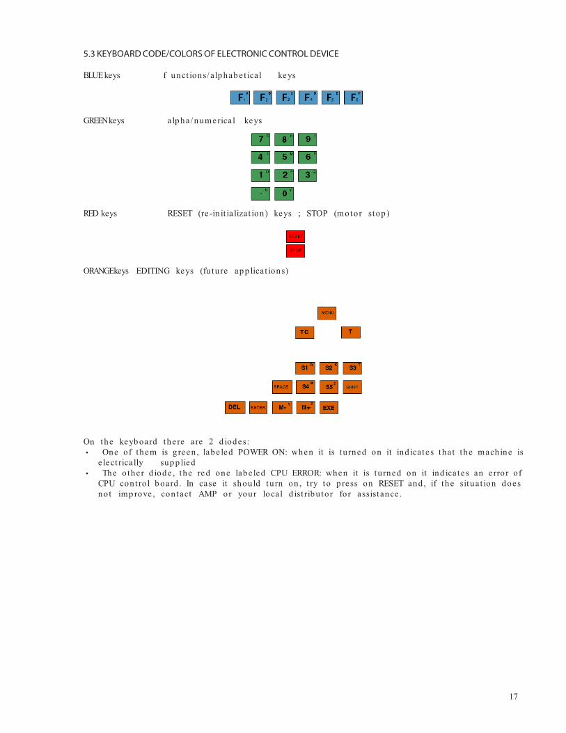
On the keyb oard the re are 2 d iod es:One of them is g reen , lab e led POWER ON: when it is tu rned on it ind icate s that the mach ine is
e lect rically sup p lied The o the r d iod e , the red one lab e led CPU ERROR: when it is tu rned on it ind icate s an e rror o fCPU cont ro l b oard . In case it shou ld tu rn on , t ry to p ress on RESET and , if the situat ion d oesnot imp rove , con tact AMP or your local d ist rib u tor for assist ance .
5.3 KEYBOARD CODE/COLORS OF ELECTRONIC CONTROL DEVICE
BLUE keys f unct ions/ alp hab e t ical keys
GREENkeys alp ha/ numerical keys
RED keys RESET (re -in it ia lizat ion ) keys ; STOP (motor stop )
ORANGEkeys EDITING keys (fu ture ap p licat ions)
18
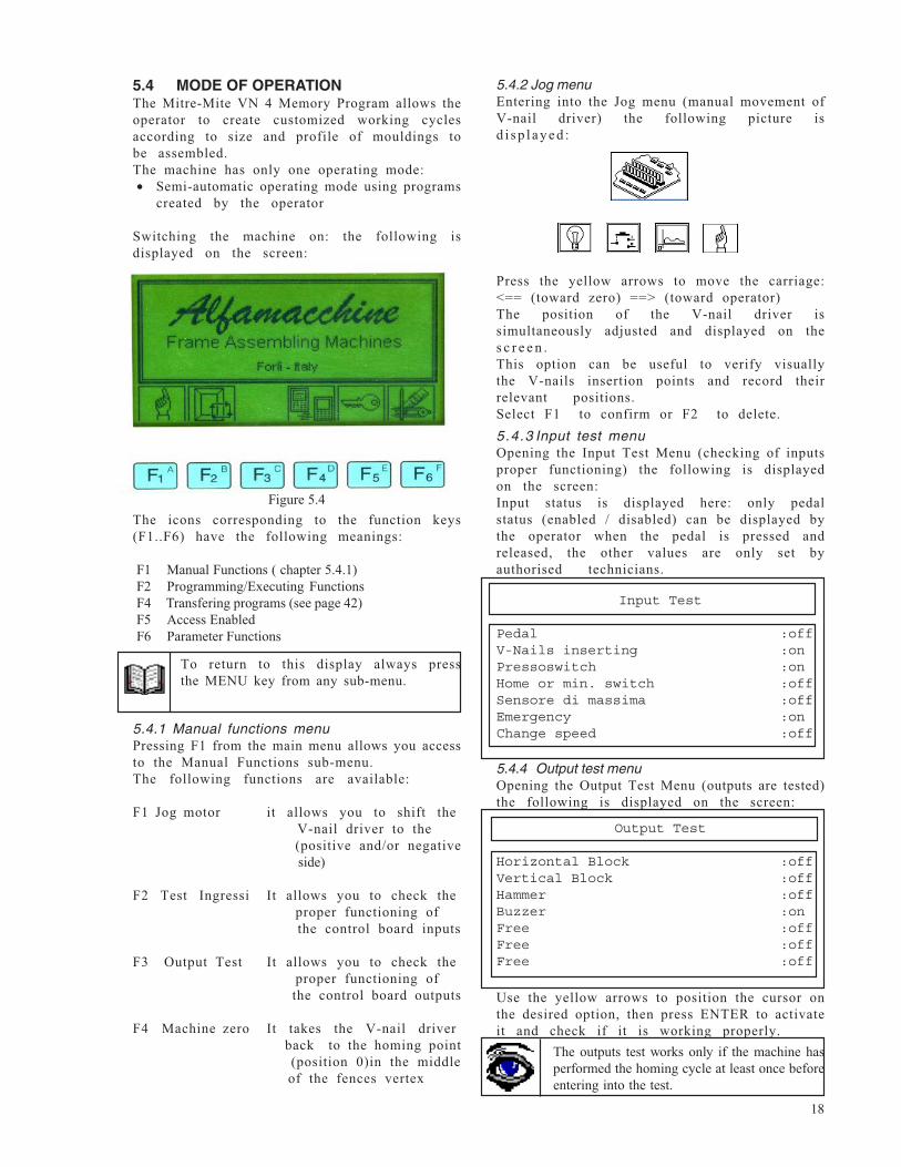
5.4 MODE OF OPERATIONThe Mitre-Mite VN 4 Memory Program allows theoperator to create customized working cyclesaccording to size and profile of mouldings tobe assembled.The machine has only one operating mode:• Semi-automatic operating mode using programs
created by the operator
Switching the machine on: the following isdisplayed on the screen:
5.4.1 Manual functions menuPressing F1 from the main menu allows you accessto the Manual Functions sub-menu.The following functions are available:
F1 Jog motor it allows you to shift the V-nail driver to the (positive and/or negative side)
F2 Test Ingressi It allows you to check the proper functioning of the control board inputs
F3 Output Test It allows you to check the proper functioning of the control board outputs
F4 Machine zero It takes the V-nail driver back to the homing point (position 0)in the middle of the fences vertex
5.4.2 Jog menuEntering into the Jog menu (manual movement ofV-nail driver) the following picture isd i s p l a y e d :
5.4.3 Input test menuOpening the Input Test Menu (checking of inputsproper functioning) the following is displayedon the screen:Input status is displayed here: only pedalstatus (enabled / disabled) can be displayed bythe operator when the pedal is pressed andreleased, the other values are only set byauthorised technicians.
5.4.4 Output test menuOpening the Output Test Menu (outputs are tested)the following is displayed on the screen:
To return to this display always pressthe MENU key from any sub-menu.
Use the yellow arrows to position the cursor onthe desired option, then press ENTER to activateit and check if it is working properly.
The outputs test works only if the machine hasperformed the homing cycle at least once beforeentering into the test.
The icons corresponding to the function keys(F1..F6) have the following meanings:
F1 Manual Functions ( chapter 5.4.1)F2 Programming/Executing FunctionsF4 Transfering programs (see page 42)F5 Access EnabledF6 Parameter Functions
Press the yellow arrows to move the carriage:<== (toward zero) ==> (toward operator)The position of the V-nail driver issimultaneously adjusted and displayed on thes c r e e n .This option can be useful to verify visuallythe V-nails insertion points and record theirrelevant positions.Select F1 to confirm or F2 to delete.
Input Test
Pedal :offV-Nails inserting :onPressoswitch :onHome or min. switch :offSensore di massima :offEmergency :onChange speed :off
Output Test
Horizontal Block :offVertical Block :offHammer :offBuzzer :onFree :offFree :offFree :off
Figure 5.4
19
5.4.6 Editing menuPressing F2 then F4 from the main menu allows you to accessto the Editing submenu.
The following functions are available:F1 Rename It permits the replacement of the name of a program previously filedF2 Copy It allows you to duplicate a program previously filedF3 Dele te It allows you to delete a program previously filedF4 Search It permits a quick search of a code number or name of a program previously memorized
When you are in this menu, you can also createnew programs.To prevent accidental variations or deletionsof the existing programs, the editing serviceis protected by an access key (password).
To enter into the Editing sub-menu you must type the accesscode which can be input:- Before entering into the Editing menu by pressing F5- After entering into the Editing menu by pressing F5 or F6
On the display you will see the request for the access code :5678
To return to the previous selectionalways press the MENU key from thesub-menu.
5.4.5 Machine zero point (homing)The V-nail driver can be positioned on zero (0)by pressing F4 on the manual functions menu.
To disable this option press SHIFT again: the diode goesoff.To delete a wrong entry shift back the <== arrow then pressDEL as many times as the number of characters you wish todelete. To add a space press on SPACE.
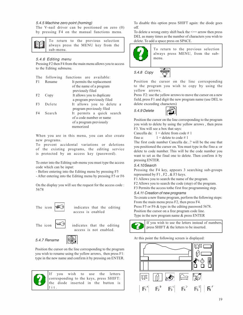
5.4.10SearchPressing the F4 key, appears 3 searching sub-groupsrepresented by F1 , F2 , & F3 keys.F1 Allows you to search the name of the program.F2 Allows you to search the code (step) of the program.F3 Permits the access tothe first free programming step.5.4.11 Creation of new programsTo create a new frame program, perform the following steps:From the main menu press F2, then press F4.Press F5 or F6 & type in the editing password 5678.Position the cursor on a free program code line.Type in the new program name & press ENTER
At this point the following screen is displayed:5.4.7 Rename
Position the cursor on the line corresponding to the programyou wish to rename using the yellow arrows, then press F1:type in the new name and confirm it by pressing on ENTER.
If you wish to use the letterscorresponding to the keys, press SHIFT:the diode inserted in the button isl i t .
To return to the previous selectionalways press MENU, from the sub-menu.
5.4.8 Copy
Position the cursor on the line correspondingto the program you wish to copy by using theyellow arrows.Press F2: use the yellow arrows to move the cursor on a newfield, press F1 and digit the new program name (use DEL todelete exceeding characters)
5.4.9 Delete
Position the cursor on the line corresponding to the programyou wish to delete by using the yellow arrows , then pressF3. You will see a box that says:Cancella da: 1 = delete from code # 1fino a: 1 = delete to code # 1The first code number Cancella da:..? will be the one thatyou positioned the cursor on. You must type in the fino a: ordelete to code number. This will be the code number youwant to set as the final one to delete. Then confirm it bypressing ENTER.
If you wish to use the letters instead of numbers,press SHIFT & the letters to be inserted.
The icon indicates that the editing access is enabled
The icon indicates that the editing access is not enabled.
20
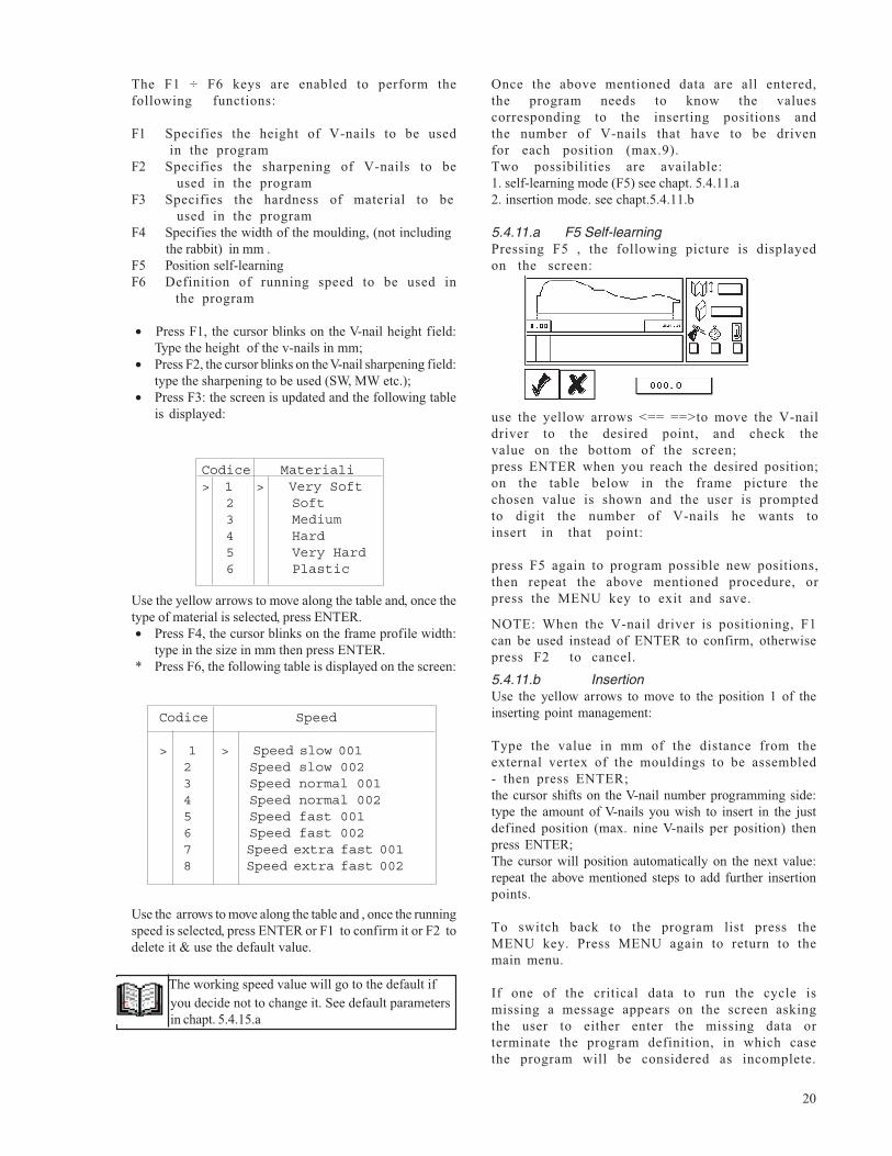
Once the above mentioned data are all entered,the program needs to know the valuescorresponding to the inserting positions andthe number of V-nails that have to be drivenfor each position (max.9).Two possibilities are available:1. self-learning mode (F5) see chapt. 5.4.11.a2. insertion mode. see chapt.5.4.11.b
5.4.11.a F5 Self-learningPressing F5 , the following picture is displayedon the screen:
use the yellow arrows <== ==>to move the V-naildriver to the desired point, and check thevalue on the bottom of the screen;press ENTER when you reach the desired position;on the table below in the frame picture thechosen value is shown and the user is promptedto digit the number of V-nails he wants toinsert in that point:
press F5 again to program possible new positions,then repeat the above mentioned procedure, orpress the MENU key to exit and save.
NOTE: When the V-nail driver is positioning, F1can be used instead of ENTER to confirm, otherwisepress F2 to cancel.
5.4.11.b InsertionUse the yellow arrows to move to the position 1 of theinserting point management:
Type the value in mm of the distance from theexternal vertex of the mouldings to be assembled- then press ENTER;the cursor shifts on the V-nail number programming side:type the amount of V-nails you wish to insert in the justdefined position (max. nine V-nails per position) thenpress ENTER;The cursor will position automatically on the next value:repeat the above mentioned steps to add further insertionpoints.
To switch back to the program list press theMENU key. Press MENU again to return to themain menu.
If one of the critical data to run the cycle ismissing a message appears on the screen askingthe user to either enter the missing data orterminate the program definition, in which casethe program will be considered as incomplete.
The F1 ÷ F6 keys are enabled to perform thefollowing functions:
F1 Specifies the height of V-nails to be used in the programF2 Specifies the sharpening of V-nails to be used in the programF3 Specifies the hardness of material to be used in the programF4 Specifies the width of the moulding, (not including the rabbit) in mm .F5 Position self-learningF6 Definition of running speed to be used in the program
• Press F1, the cursor blinks on the V-nail height field:Type the height of the v-nails in mm;
• Press F2, the cursor blinks on the V-nail sharpening field:type the sharpening to be used (SW, MW etc.);
• Press F3: the screen is updated and the following tableis displayed:
Use the yellow arrows to move along the table and, once thetype of material is selected, press ENTER.• Press F4, the cursor blinks on the frame profile width:
type in the size in mm then press ENTER.* Press F6, the following table is displayed on the screen:
Use the arrows to move along the table and , once the runningspeed is selected, press ENTER or F1 to confirm it or F2 todelete it & use the default value.
Codice Materiali> 1 > Very Soft 2 Soft 3 Medium 4 Hard 5 Very Hard 6 Plastic
Codice Speed
> 1 > Speed slow 001 2 Speed slow 002 3 Speed normal 001 4 Speed normal 002 5 Speed fast 001 6 Speed fast 002 7 Speed extra fast 001 8 Speed extra fast 002
The working speed value will go to the default ifyou decide not to change it. See default parametersin chapt. 5.4.15.a
21
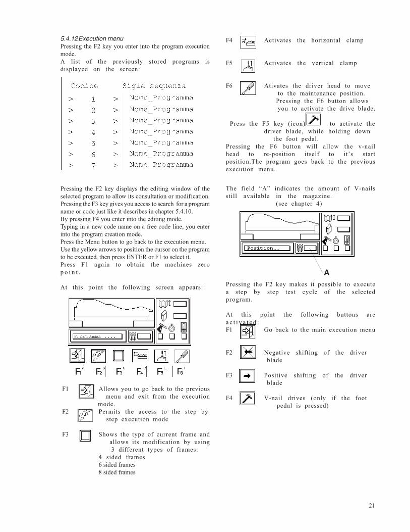
5.4.12Execution menuPressing the F2 key you enter into the program executionmode.A list of the previously stored programs isdisplayed on the screen:
Pressing the F2 key displays the editing window of theselected program to allow its consultation or modification.Pressing the F3 key gives you access to search for a programname or code just like it describes in chapter 5.4.10.By pressing F4 you enter into the editing mode.Typing in a new code name on a free code line, you enterinto the program creation mode.Press the Menu button to go back to the execution menu.Use the yellow arrows to position the cursor on the programto be executed, then press ENTER or F1 to select it.Press F1 again to obtain the machines zerop o i n t .
At this point the following screen appears:
The field “A” indicates the amount of V-nailsstill available in the magazine. (see chapter 4)
APressing the F2 key makes it possible to executea step by step test cycle of the selectedprogram.
F4 Activates the horizontal clamp
F5 Activates the vertical clamp
F6 Ativates the driver head to move to the maintenance position. Pressing the F6 button allows you to activate the drive blade.
Press the F5 key (icon) to activate thedriver blade, while holding down
the foot pedal.Pressing the F6 button will allow the v-nailhead to re-position itself to it’s startposition.The program goes back to the previousexecution menu.
At this point the following buttons area c t i v a t e d :F1 Go back to the main execution menu
F2 Negative shifting of the driver blade
F3 Positive shifting of the driver blade
F4 V-nail drives (only if the foot pedal is pressed)
F1 Allows you to go back to the previous menu and exit from the execution mode.F2 Permits the access to the step by step execution mode
F3 Shows the type of current frame and allows its modification by using 3 different types of frames:
4 sided frames6 sided frames8 sided frames
22
5.4.14Enabling access code protected servicesThe F5 key on the main menu (see figure 5.4)allows the operator to enable some access codeprotected submenus.Its graphic representation shows the insertedaccess level.
Such menus are:• Parameter Menu F6• Editing Menu F2
Default access keys are:Parameters (speed delays) 1234Ed i t ing 5678Reset counter 9999
These keys can be modified with the help of authorizedstaff.
If you set the Edit password to “0”, the editing password will no longer be asked for.
To enable the codes proceed as follows:Press the F5 button from the main menu and when the requestmessage appears, insert the code.
In the step-by-step mode, the variousfiring positions can be chosen evenif the moulding is not clamped, butV-nails can only be fired (F4 if thefoot-pedal is pressed, and themouldings are safely clamped.
Press F1 to go back to the main execution menu.After pressing F1 the V-nail driver willautomatically go to the first programmedinsertion position.
When you are in the main execution menu operateas follows:1. Place the moldings onto the machine andadjust the vertical horizontal clamps (SeeChapter 4.9.2 and 4.9.3).2. Press the foot pedal to obtain a completeworking cycle; release the pedal once the cycleis completed to disable the vertical and thehorizontal clamps. This will also repositionthe V-nail driver on the first insertion pointof the programmed sequence.Press F1 to go back to the previous menu.
In the program execution screen the followingfunctions are activated:TC KEY: visualizes the machines production data.V-nails daily consumption: resettable by pressing F1V-nails total consumptionFrames productionRectangular frames production resettable by pressing F3Hexagonal frames production resettable by pressing F4Octagonal frames production resettable by pressing F5Press the Menu key to go back to the previouss c r e e n .
T KEY: Allows the adjustment of the verticalclamping times with respect to the currentspeed during the working cycle.
The T-key is activated only whenyou use the access code 1234
5.4.13 Working speed modificationTo modify the working speed use the keysS1.....S4 or SHIFT+S1.....SHIFT+S4. Available are 8 different speed levels:S1 slow speed 1S2 slow speed 2S3 normal speed 1S4 normal speed 2S5 fast speed 1S6 fast speed 2S7 extra fast speed 1S8 extra fast speed 2
Once the speed level is selected, confirm it bypressing ENTER.
To execute a manual test cycle:Place the mouldings on the machine. Adjust thevertical and the horizontal clamps (See Chapter4.9.2 and 4.9.3);1. Press the foot pedal to lock the mouldingsand hold it down;2. Press the F4 key to insert one V-nail. Pressit again so the driver blade goes down.If youwant more v-nails, repeat the process.3. Press the F3 key to position the driver onthe next insertion point, then repeat step 34. Repeat steps 2 and 3 until the icon of the F3key changes: this means that there are no furtherprogrammed points. The same applies to the F2key whose icon means that no insertion pointshave been programmed prior to the one in whichthe V-nail driver is currently positioned.5. The drivers current position is displayed onthe bottom left side of the screen, under theframe outline.
The operator has the possibility ofchanging the working speed while themachine is running by using the keysS1...S4 or (shift). S1...S4 is enabledby a password parameter.This option will be agreed upon duringthe contractual phase and pre-disposed on the machine at its origin.
23
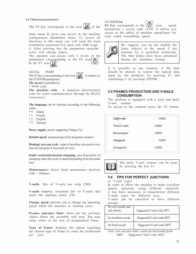
5.4.15Machine parameters
The F6 key corresponds to the icon of the
main menu & gives you access to the machineconfiguration parameters menu. To access allfunctions in this menu you will need the maininstallation password.You must call AMP to getit. After entering into the parameters menu theicons will change places.The operator can access only 2 levels of theparameters corresponding to the F6 icon& the F5 icon
5.4.15.A. F5 KEYThe F5 key (corresponding to the icon is relative tothe CUSTOM parameters.The access is possible by:* 9999 codeThe machine code : A (machine identificationcode for serial communication through the RS232connector)
The language can be selected according to the followingcodes:* 0 Italian* 1 French* 2 English* 3 German
Power supply: power supplying Voltage (%)
Default speed: proposed speed for programs creation
Homing/ zero any cycle : input of machine zero point everytime the program is executed (si=yes)
Pedal vertical/horizontal clamping: pre-disposition ofclamping when the cycle is ended depending from the pedal(no)
Maintenance: driver head maintenance position(100 = 100mm)
V-nails: Qty of V-nails per strip (200)
V-nails reserve: minimum Qty of V-nails thatstarts the machine alarm (10)
Change speed: permits you to change the operatingspeed while the machine is running (yes)
Frames min/max limit: these are the min/maxvalues where the assembly will stop. The maxvalue refers to the size of programmed frame
Type of frame: displays the option regardingthe chosen type of frame to count the production(si= yes)
It is possible at any moment, if the datashould be altered, to restore the typical datainput by the producer, by pressing F1 andconfirming it by pressing ENTER
We suggest: you do not modify thetimes relative to the speed if notassisted by a qualified technician.The time delays have been calculatedduring the machines testing.
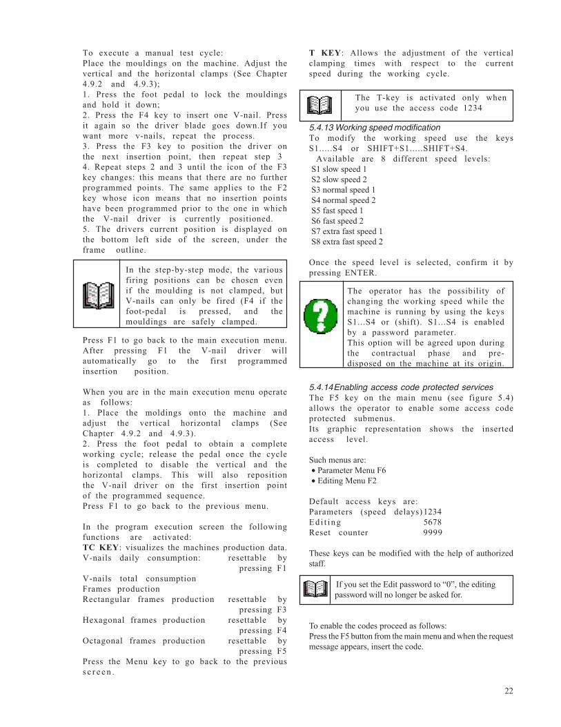
5.5 FRAMES PRODUCTION AND V-NAILSCONSUMPTION
The machine is equipped with a total and dailyV-nail counter.To access to the counters press the TC button.
The daily V-nail counter can be resetby pressing the key F1
5.6 TIPS FOR PERFECT JUNCTIONSa) V-nail typesIn order to allow the machine to make excellentquality junctions using different materials,it has been necessary to manufacture differentV-nails types for different uses.V-nails can be classified in three differentgroups :for soft woods andsoft plastic Suggested V-nail code SPT
for medium woods Suggested V-nail code HPT
for hard woods Suggested V-nail code HPT
Daily V-nails : XXXX
Total V-nails : XXXX
Rectangular : XXXX
Hexagonal : XXXX
Octagonal : XXXX
5.4.15.B F6 keyF6 key corresponds to the icon: speedparameters; ( access code 1234). It allows youaccess to the tables of machine speed/times foreach listed assembling speed.
Note: you can also order v-nails for horizontal grainMDF Suggested V-Nail Code: HDF
24
5.7 MACHINE STOPThe machine can work only by pressing theelectric pedal; to stop it mid-cycle press thered emergency stop button on the keypad.It is possible also to disconnect the fastclutch fitting from the compressed air or isolateelectrically the machine by the special switchlocated on the floor stand.
5.8 PUTTING OUT OF SERVICEIn case on long inactivity periods it isnecessary to disconnect the fast clutch fittingfrom pneumatic system and the power supplyc a b l e .
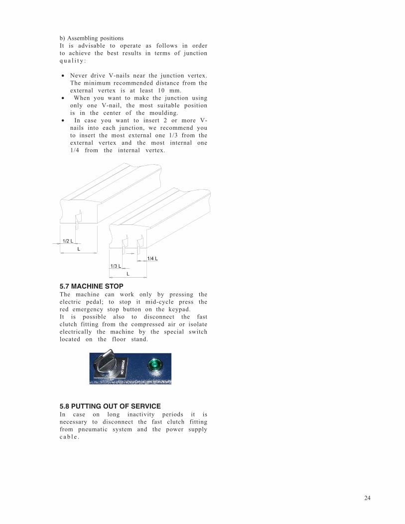
b) Assembling positionsIt is advisable to operate as follows in orderto achieve the best results in terms of junctionq u a l i t y :
• Never drive V-nails near the junction vertex.The minimum recommended distance from theexternal vertex is at least 10 mm.
• When you want to make the junction usingonly one V-nail, the most suitable positionis in the center of the moulding.
• In case you want to insert 2 or more V-nails into each junction, we recommend youto insert the most external one 1/3 from theexternal vertex and the most internal one1/4 from the internal vertex.
25
6. PROGRAMMING
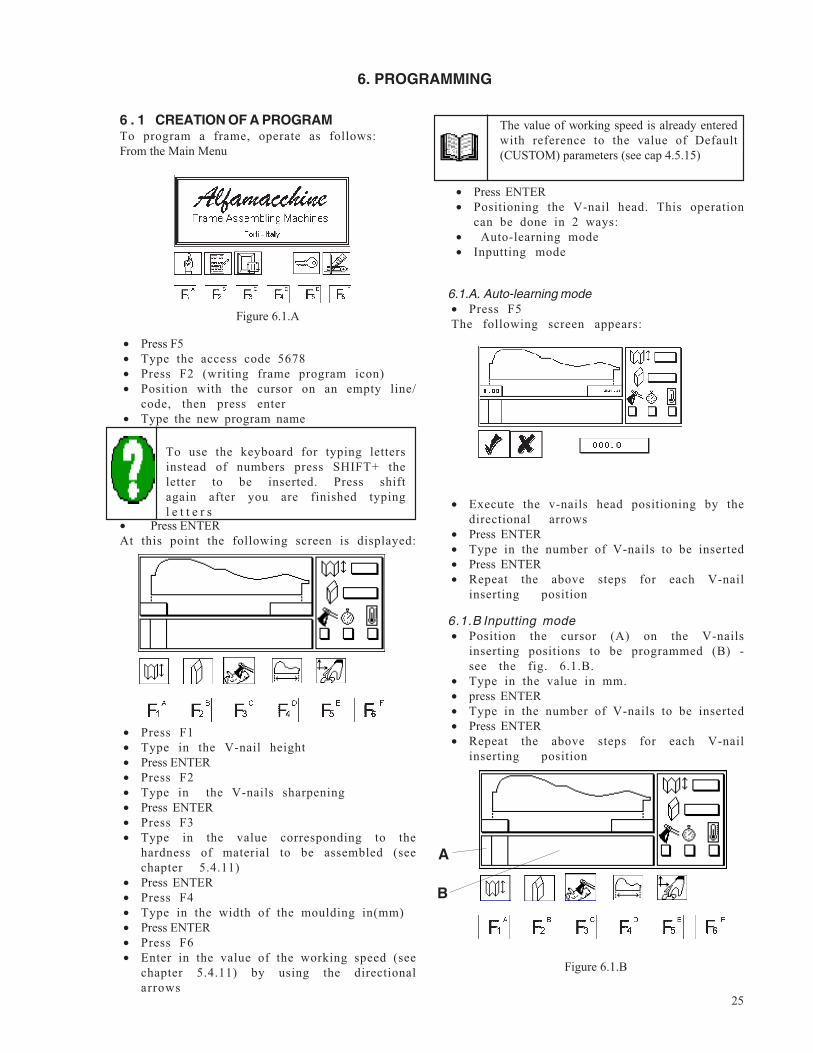
6 . 1 CREATION OF A PROGRAMTo program a frame, operate as follows:From the Main Menu
• Press F5• Type the access code 5678• Press F2 (writing frame program icon)• Position with the cursor on an empty line/
code, then press enter• Type the new program name
To use the keyboard for typing lettersinstead of numbers press SHIFT+ theletter to be inserted. Press shiftagain after you are finished typingl e t t e r s
• Press ENTERAt this point the following screen is displayed:
• Press F1• Type in the V-nail height• Press ENTER• Press F2• Type in the V-nails sharpening• Press ENTER• Press F3• Type in the value corresponding to the
hardness of material to be assembled (seechapter 5.4.11)
• Press ENTER• Press F4• Type in the width of the moulding in(mm)• Press ENTER• Press F6• Enter in the value of the working speed (see
chapter 5.4.11) by using the directionalarrows
The value of working speed is already enteredwith reference to the value of Default(CUSTOM) parameters (see cap 4.5.15)
• Press ENTER• Positioning the V-nail head. This operation
can be done in 2 ways:• Auto-learning mode• Inputting mode
6.1.A. Auto-learning mode• Press F5The following screen appears:
• Execute the v-nails head positioning by thedirectional arrows
• Press ENTER• Type in the number of V-nails to be inserted• Press ENTER• Repeat the above steps for each V-nail
inserting position
6.1.B Inputting mode• Position the cursor (A) on the V-nails
inserting positions to be programmed (B) -see the fig. 6.1.B.
• Type in the value in mm.• press ENTER• Type in the number of V-nails to be inserted• Press ENTER• Repeat the above steps for each V-nail
inserting position
Figure 6.1.B
Figure 6.1.A
A
B
26
7. EXECUTION OF THE PROGRAM
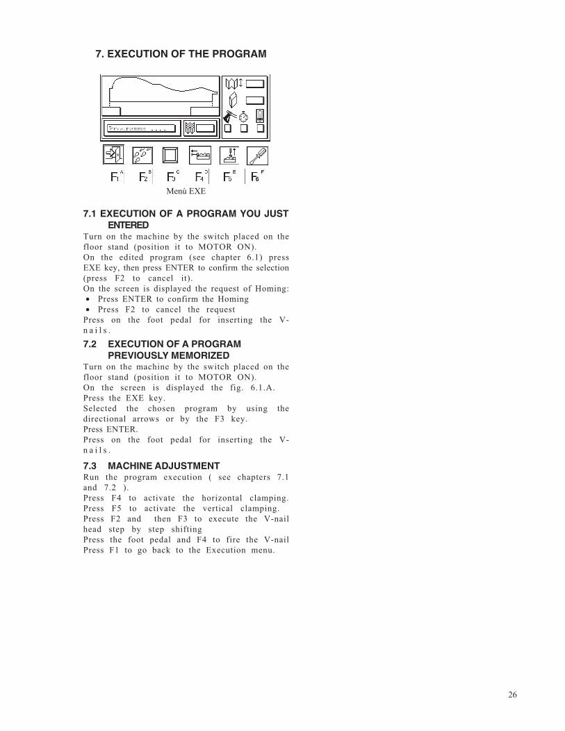
Menù EXE
7.1 EXECUTION OF A PROGRAM YOU JUSTENTERED
Turn on the machine by the switch placed on thefloor stand (position it to MOTOR ON).On the edited program (see chapter 6.1) pressEXE key, then press ENTER to confirm the selection(press F2 to cancel it).On the screen is displayed the request of Homing:• Press ENTER to confirm the Homing• Press F2 to cancel the request
Press on the foot pedal for inserting the V-n a i l s .
7.2 EXECUTION OF A PROGRAMPREVIOUSLY MEMORIZED
Turn on the machine by the switch placed on thefloor stand (position it to MOTOR ON).On the screen is displayed the fig. 6.1.A.Press the EXE key.Selected the chosen program by using thedirectional arrows or by the F3 key.Press ENTER.Press on the foot pedal for inserting the V-n a i l s .
7.3 MACHINE ADJUSTMENTRun the program execution ( see chapters 7.1and 7.2 ).Press F4 to activate the horizontal clamping.Press F5 to activate the vertical clamping.Press F2 and then F3 to execute the V-nailhead step by step shiftingPress the foot pedal and F4 to fire the V-nailPress F1 to go back to the Execution menu.
27
8. MAINTENANCE
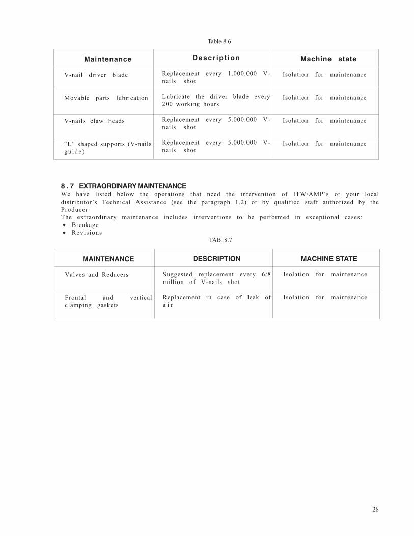
8.1 STATE OF MAINTENANCEThe maintenance operations must be performed with the machine in the conditions described at theparagraph “state of the machine” in the tables 8.6 and 8.7.
8.6 ORDINARY MAINTENANCEThe following operations must be executed on the times indicated here below. Not observing thefollowing instructions exonerate the Producer from any responsibility regarding the warranty.The operations described here below, even if simple, must be executed by qualified personnel.The scheduled ordinary maintenance includes overhauls, checks and interventions that, to preventstops and breakdowns, keep under systematic control:• Lubrication state of the machine• Wear and tear parts state
8.2 MACHINE ISOLATIONBefore performing any type of maintenance or repair , it is necessary to isolate the machine fromthe feeding sources, making the following operations:1) Disconnect the plug from the electric socket.2) Disconnect the fast clutch fitting from the pneumatic system.
8.3 SPECIAL CAUTIONSDuring the maintenance or repair operations we suggested to proceed as follows:- Before starting any operation place a sign-board “machine under maintenance” in a well visible
p o s i t i o n- Do not use solvents or flammable materials- Do not step on the machine parts, because they have not been projected to sustain the weight
of persons.- Disconnect the power supply from the electric system & disconnect the air supply- Once all the operations are finished, restore and place properly the protections and shields
removed or opened
8.5 LUBRICATION
Fill your lubricator with oil, use CASTROL MAGNA GC 32 or equivalent oil. Do not use oil with heavycleaners in it.Furthermore, we recommend you lubricate the driver blade every 200 working hours.
ATTENTION: Unsuitable lubricants may cause valve seal problems (seals may become too large) andconsequent Valve jamming.
If you use glue when joining frames, we suggest you lubricate thedriver blade daily.
8.4 CLEANINGThe machine structure is simple and robust therefore the mechanical parts do not require anyspecial maintenance.It is recommended that you follow the rules listed here below:- Regularly remove glue or other residues from the V-nail head and from the upper part of the
driver blade;- always keep the V-nails magazine clean- remove any residue from the V-nail guide “L” shaped support.
Do not use water to clean the machine, otherwise the metallic parts may oxidise.
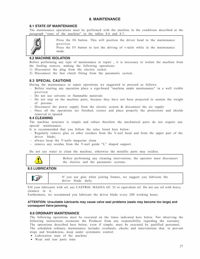
Press the F6 button. This will position the driver head to the maintenancep o s i t i o n .Press the F5 button to test the driving of v-nails while in the maintenancemode.
Before performing any cleaning intervention, the operator must disconnectthe electric and the pneumatic systems.
28
TAB. 8.7
Table 8.6
8 . 7 EXTRAORDINARY MAINTENANCEWe have listed below the operations that need the intervention of ITW/AMP’s or your localdistributor’s Technical Assistance (see the paragraph 1.2) or by qualified staff authorized by theProducerThe extraordinary maintenance includes interventions to be performed in exceptional cases:• Breakage• Revisions
Maintenance
V-nail driver blade
Movable parts lubrication
V-nails claw heads
“L” shaped supports (V-nailsgu ide )
Descr ip t ion
Replacement every 1.000.000 V-nails shot
Lubricate the driver blade every200 working hours
Replacement every 5.000.000 V-nails shot
Replacement every 5.000.000 V-nails shot
Machine state
Isolation for maintenance
Isolation for maintenance
Isolation for maintenance
Isolation for maintenance
MAINTENANCE
Valves and Reducers
Frontal and verticalclamping gaskets
DESCRIPTION
Suggested replacement every 6/8million of V-nails shot
Replacement in case of leak ofa i r
MACHINE STATE
Isolation for maintenance
Isolation for maintenance
29
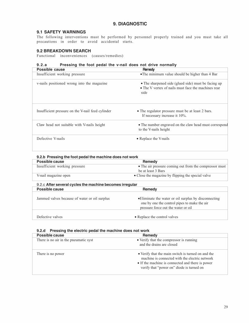
9. DIAGNOSTIC
9.1 SAFETY WARNINGSThe following interventions must be performed by personnel properly trained and you must take allprecautions in order to avoid accidental starts.
9.2 BREAKDOWN SEARCHFunctional inconveniences (causes/remedies)
9.2.a Pressing the foot pedal the v-nail does not drive normallyPossible cause RemedyInsufficient working pressure •The minimum value should be higher than 4 Bar
v-nails positioned wrong into the magazine • The sharpened side (glued side) must be facing up • The V vertex of nails must face the machines rear
side
Insufficient pressure on the V-nail feed cylinder • The regulator pressure must be at least 2 bars. If necessary increase it 10%.
Claw head not suitable with V-nails height • The number engraved on the claw head must correspond to the V-nails height
Defective V-nails • Replace the V-nails
9.2.b Pressing the foot pedal the machine does not workPossible cause RemedyInsufficient working pressure • The air pressure coming out from the compressor must
be at least 3 BarsV-nail magazine open • Close the magazine by flipping the special valve
9.2.c After several cycles the machine becomes irregularPossible cause Remedy
Jammed valves because of water or oil surplus •Eliminate the water or oil surplus by disconnecting one by one the control pipes to make the air pressure force out the water or oil
Defective valves • Replace the control valves
9.2.d Pressing the electric pedal the machine does not workPossible cause RemedyThere is no air in the pneumatic syst • Verify that the compressor is running
and the drains are closed
There is no power • Verify that the main switch is turned on and the machine is connected with the electric network
• If the machine is connected and there is power verify that “power on” diode is turned on
30
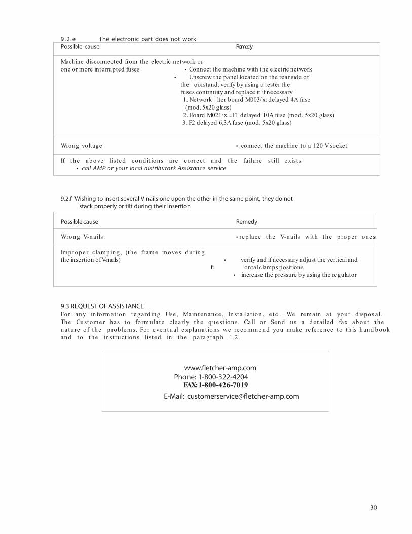
9.2 .e The electronic part does not workPossible cause Remedy
Machine disconnected from the electric network orone or more interrupted fuses Connect the machine with the electric network
Unscrew the panel located on the rear side ofthe oorstand: verify by using a tester thefuses continuity and replace it if necessary1. Network lter board M003/x: delayed 4A fuse(mod. 5x20 glass)
2. Board M021/x....F1 delayed 10A fuse (mod. 5x20 glass)3. F2 delayed 6,3A fuse (mod. 5x20 glass)
Wrong voltage connect the machine to a 120 V socket
If the ab ove list ed cond it ions are correct and the failu re st ill exist scall AMP or your local distributor’s Assistance service
9.2.f Wishing to insert several V-nails one upon the other in the same point, they do not stack properly or tilt during their insertion
Possible cause Remedy
Wrong V-nails rep lace the V-nails with the p rop er ones
Imp rop e r clamp ing , (the frame moves d uringthe insertion of V-nails) verify and if necessary adjust the vertical and
fr ontal clamps positions increase the pressure by using the regulator
9.3 REQUEST OF ASSISTANCEFor any in format ion regard ing Use , Main tenance , Insta lla t ion , e tc.. We remain at your d isp osal.The Customer has to formulate clearly the q uest ions. Call o r Send us a d e tailed fax ab out thenatu re of the p rob lems. For even tual exp lanat ions we recommend you make re fe rence to th is hand b ookand to the inst ruct ions list ed in the p arag rap h 1.2.
www.fletcher-amp.comPhone: 1-800-322-4204
FAX: 1-800-426-7019E-Mail: [email protected]
31
10.2 SPARE PARTS ORDERINGWe remind you that only a qualified technician can repair the machine.Thus, we suggest the intervention of AMP’s or your local distributor’s Center of TechnicalAssistance, which has the qualified staff, proper equipment and tools, and uses original sparep a r t s .To order the spare parts listed above, send by fax or letter (see chapter 7.3) the following data:- Model of the Machine- Code of mechanical drawing- Reference number of spare part or group indicated on the mechanic drawing- Code/part number of single or group spare part
11.1 DEMOLITIONAt the act of demolition it is necessary to separate the parts in plastic material from electric components.Most countriesrequire this, respecting the current Norms.Concerning the machine metallic mass, it is enough the subdivision between the steel parts and those of other metals oralloys, for a proper recycling by smelting.
11. DEMOLITION
12.1 DECLARATIONSYou can find here attached the following declarations:
Declaration of conformity to the Norm 89/392/CEE Declaration of conformity to the Norm 89/336/CEE
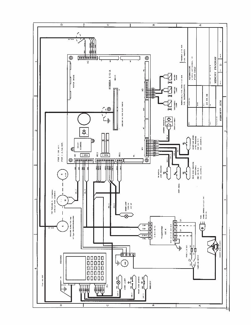
12.2 SCHEMESYou can find here attached the following schemes:
(A) Mechanic Schemes (B) Pneumatic Scheme (C) Plates Dislocation (D) Sharpening Table (E) Electric Scheme
12. ATTACHMENTS
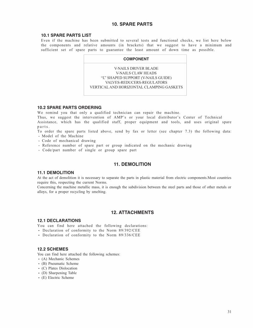
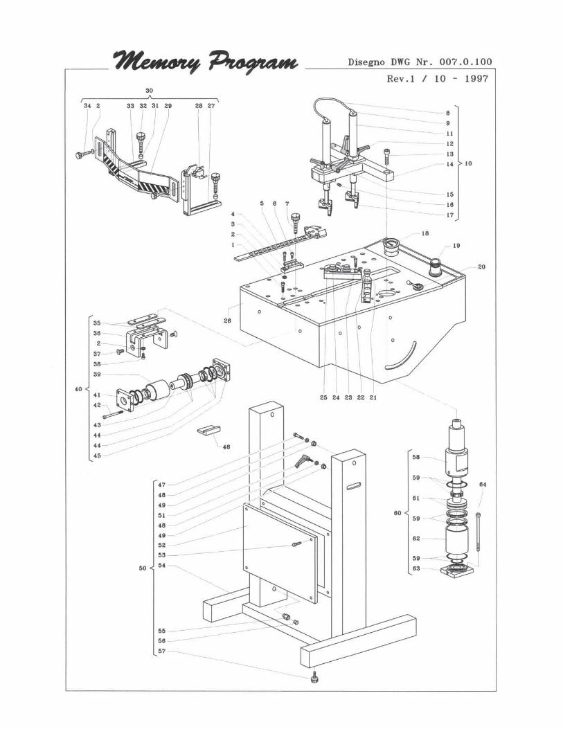
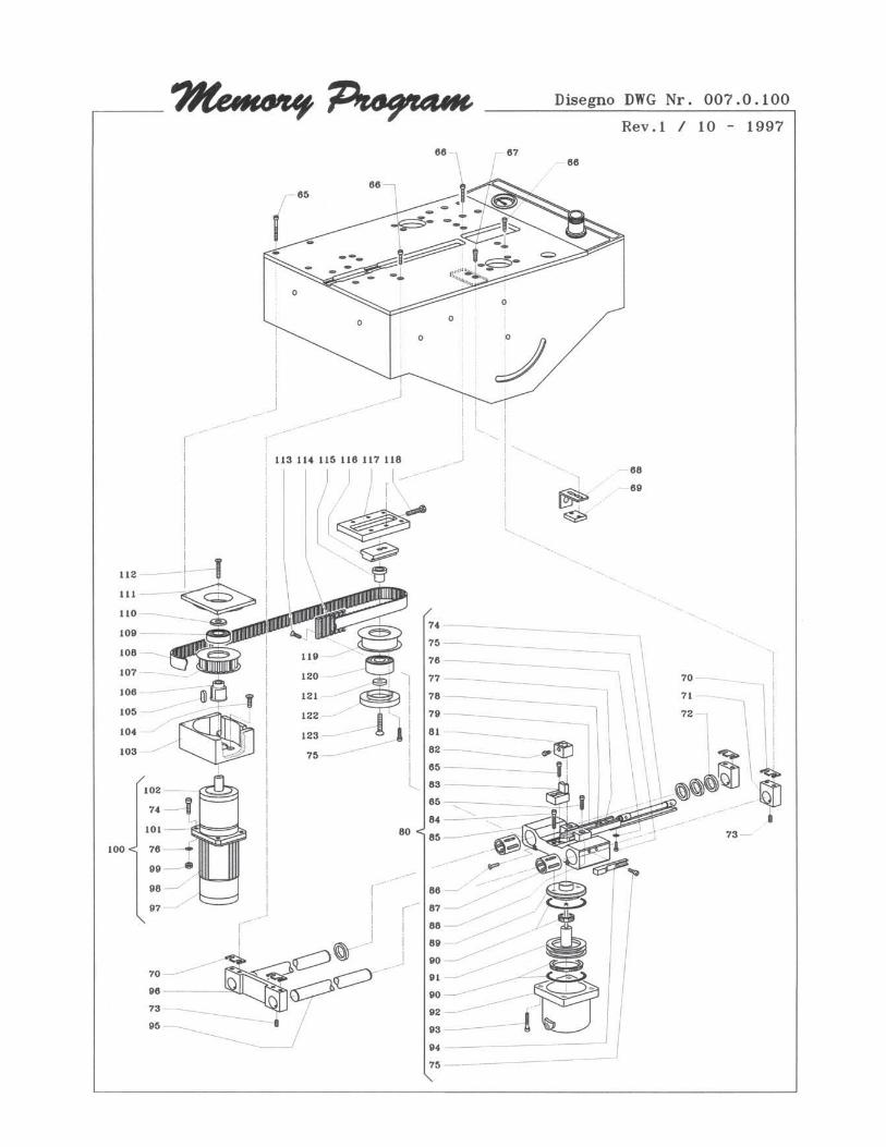
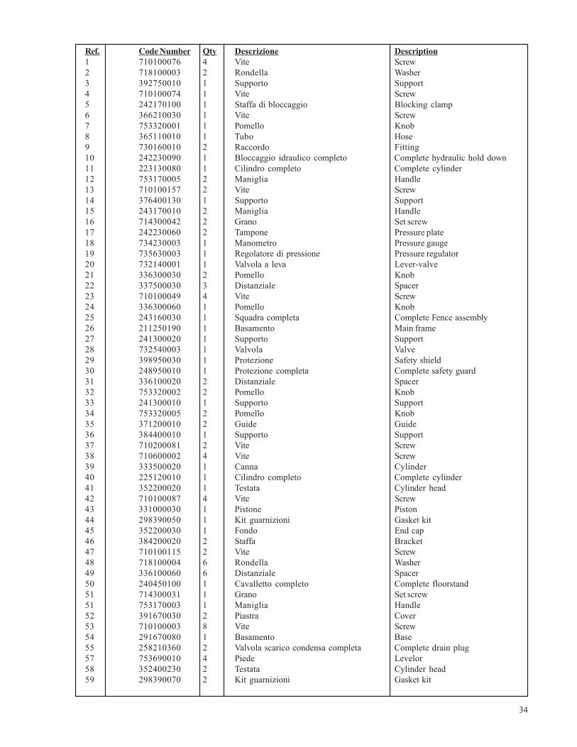
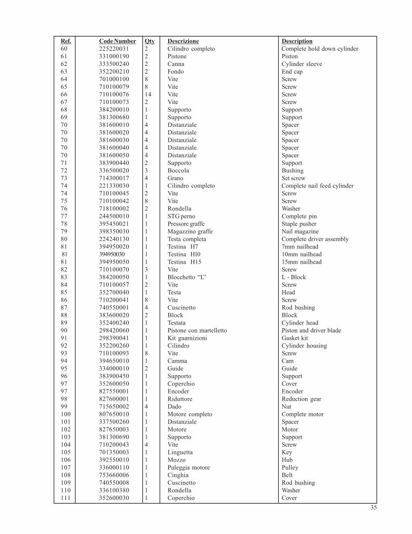
10.1 SPARE PARTS LISTEven if the machine has been submitted to several tests and functional checks, we list here belowthe components and relative amounts (in brackets) that we suggest to have a minimum andsufficient set of spare parts to guarantee the least amount of down time as possible.
COMPONENT
V-NAILS DRIVER BLADEV-NAILS CLAW HEADS
“L” SHAPED SUPPORT (V-NAILS GUIDE)VALVES-REDUCERS-REGULATORS
VERTICAL AND HORIZONTAL CLAMPING GASKETS
10. SPARE PARTS
32
33
34
Ref. Code Number Qty Descrizione Description1 710100076 4 Vite Screw2 718100003 2 Rondella Washer3 392750010 1 Supporto Support4 710100074 1 Vite Screw5 242170100 1 Staffa di bloccaggio Blocking clamp6 366210030 1 Vite Screw7 753320001 1 Pomello Knob8 365110010 1 Tubo Hose9 730160010 2 Raccordo Fitting10 242230090 1 Bloccaggio idraulico completo Complete hydraulic hold down11 223130080 1 Cilindro completo Complete cylinder12 753170005 2 Maniglia Handle13 710100157 2 Vite Screw14 376400130 1 Supporto Support15 243170010 2 Maniglia Handle16 714300042 2 Grano Set screw17 242230060 2 Tampone Pressure plate18 734230003 1 Manometro Pressure gauge19 735630003 1 Regolatore di pressione Pressure regulator20 732140001 1 Valvola a leva Lever-valve21 336300030 2 Pomello Knob22 337500030 3 Distanziale Spacer23 710100049 4 Vite Screw24 336300060 1 Pomello Knob25 243160030 1 Squadra completa Complete Fence assembly26 211250190 1 Basamento Main frame27 241300020 1 Supporto Support28 732540003 1 Valvola Valve29 398950030 1 Protezione Safety shield30 248950010 1 Protezione completa Complete safety guard31 336100020 2 Distanziale Spacer32 753320002 2 Pomello Knob33 241300010 1 Supporto Support34 753320005 2 Pomello Knob35 371200010 2 Guide Guide36 384400010 1 Supporto Support37 710200081 2 Vite Screw38 710600002 4 Vite Screw39 333500020 1 Canna Cylinder40 225120010 1 Cilindro completo Complete cylinder41 352200020 1 Testata Cylinder head42 710100087 4 Vite Screw43 331000030 1 Pistone Piston44 298390050 1 Kit guarnizioni Gasket kit45 352200030 1 Fondo End cap46 384200020 2 Staffa Bracket47 710100115 2 Vite Screw48 718100004 6 Rondella Washer49 336100060 6 Distanziale Spacer50 240450100 1 Cavalletto completo Complete floorstand51 714300031 1 Grano Set screw51 753170003 1 Maniglia Handle52 391670030 2 Piastra Cover53 710100003 8 Vite Screw54 291670080 1 Basamento Base55 258210360 2 Valvola scarico condensa completa Complete drain plug57 753690010 4 Piede Levelor58 352400230 2 Testata Cylinder head59 298390070 2 Kit guarnizioni Gasket kit
35
Ref. Code Number Qty Descrizione Description60 225220031 2 Cilindro completo Complete hold down cylinder61 331000190 2 Pistone Piston62 333500240 2 Canna Cylinder sleeve63 352200210 2 Fondo End cap64 701000100 8 Vite Screw65 710100079 8 Vite Screw66 710100076 14 Vite Screw67 710100073 2 Vite Screw68 384200010 1 Supporto Support69 381300680 1 Supporto Support70 381600010 4 Distanziale Spacer70 381600020 4 Distanziale Spacer70 381600030 4 Distanziale Spacer70 381600040 4 Distanziale Spacer70 381600050 4 Distanziale Spacer71 383900440 2 Supporto Support72 336500020 3 Boccola Bushing73 714300017 4 Grano Set screw74 221330030 1 Cilindro completo Complete nail feed cylinder74 710100045 2 Vite Screw75 710100042 8 Vite Screw76 718100002 2 Rondella Washer77 244500010 1 STG perno Complete pin78 395450021 1 Pressore graffe Staple pusher79 398350030 1 Magazzino graffe Nail magazine80 224240130 1 Testa completa Complete driver assembly81 394950020 1 Testina H7 7mm nailhead 81 394950030 1 Testina H10 10mm nailhead81 394950050 1 Testina H15 15mm nailhead82 710100070 3 Vite Screw83 384200050 1 Blocchetto “L” L - Block84 710100057 2 Vite Screw85 352700040 1 Testa Head86 710200041 8 Vite Screw87 740550001 4 Cuscinetto Rod bushing88 383600020 2 Block Block89 352400240 1 Testata Cylinder head90 298420060 1 Pistone con martelletto Piston and driver blade91 298390041 1 Kit guarnizioni Gasket kit92 352200260 1 Cilindro Cylinder housing93 710100093 8 Vite Screw94 394650010 1 Camma Cam95 334000010 2 Guide Guide96 383900450 1 Supporto Support97 352600050 1 Coperchio Cover97 827550001 1 Encoder Encoder98 827600001 1 Riduttore Reduction gear99 715650002 4 Dado Nut100 807650010 1 Motore completo Complete motor101 337500260 1 Distanziale Spacer102 827650003 1 Motore Motor103 381300690 1 Supporto Support104 710200043 4 Vite Screw105 701350003 1 Linguetta Key106 392550010 1 Mozzo Hub107 336000110 1 Puleggia motore Pulley108 753660006 1 Cinghia Belt109 740550008 1 Cuscinetto Rod bushing110 336100380 1 Rondella Washer111 352600030 1 Coperchio Cover
36
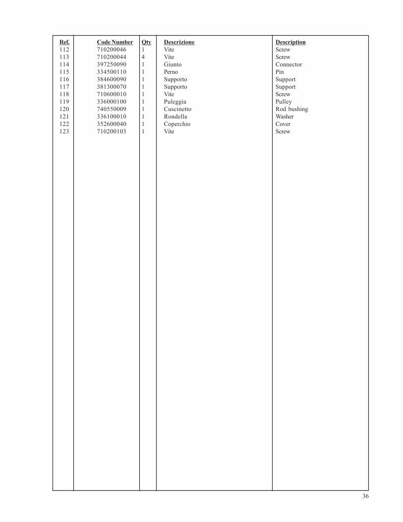
Ref. Code Number Qty Descrizione Description112 710200046 1 Vite Screw113 710200044 4 Vite Screw114 397250090 1 Giunto Connector115 334500110 1 Perno Pin116 384600090 1 Supporto Support117 381300070 1 Supporto Support118 710600010 1 Vite Screw119 336000100 1 Puleggia Pulley120 740550009 1 Cuscinetto Rod bushing121 336100010 1 Rondella Washer122 352600040 1 Coperchio Cover123 710200103 1 Vite Screw
37
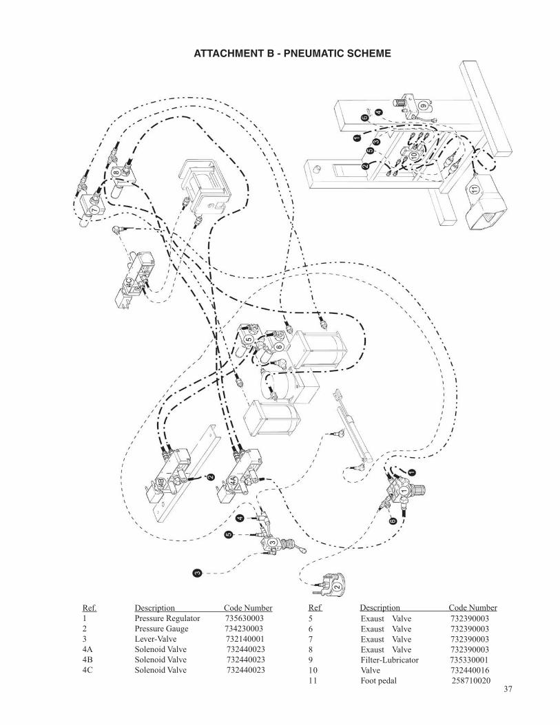
ATTACHMENT B - PNEUMATIC SCHEME
Ref. Description Code Number1 Pressure Regulator 7356300032 Pressure Gauge 7342300033 Lever-Valve 7321400014A Solenoid Valve 7324400234B Solenoid Valve 7324400234C Solenoid Valve 732440023
5 Exaust Valve 7323900036 Exaust Valve 7323900037 Exaust Valve 7323900038 Exaust Valve 7323900039 Filter-Lubricator 73533000110 Valve 73244001611 Foot pedal 258710020
Ref Description Code Number
38
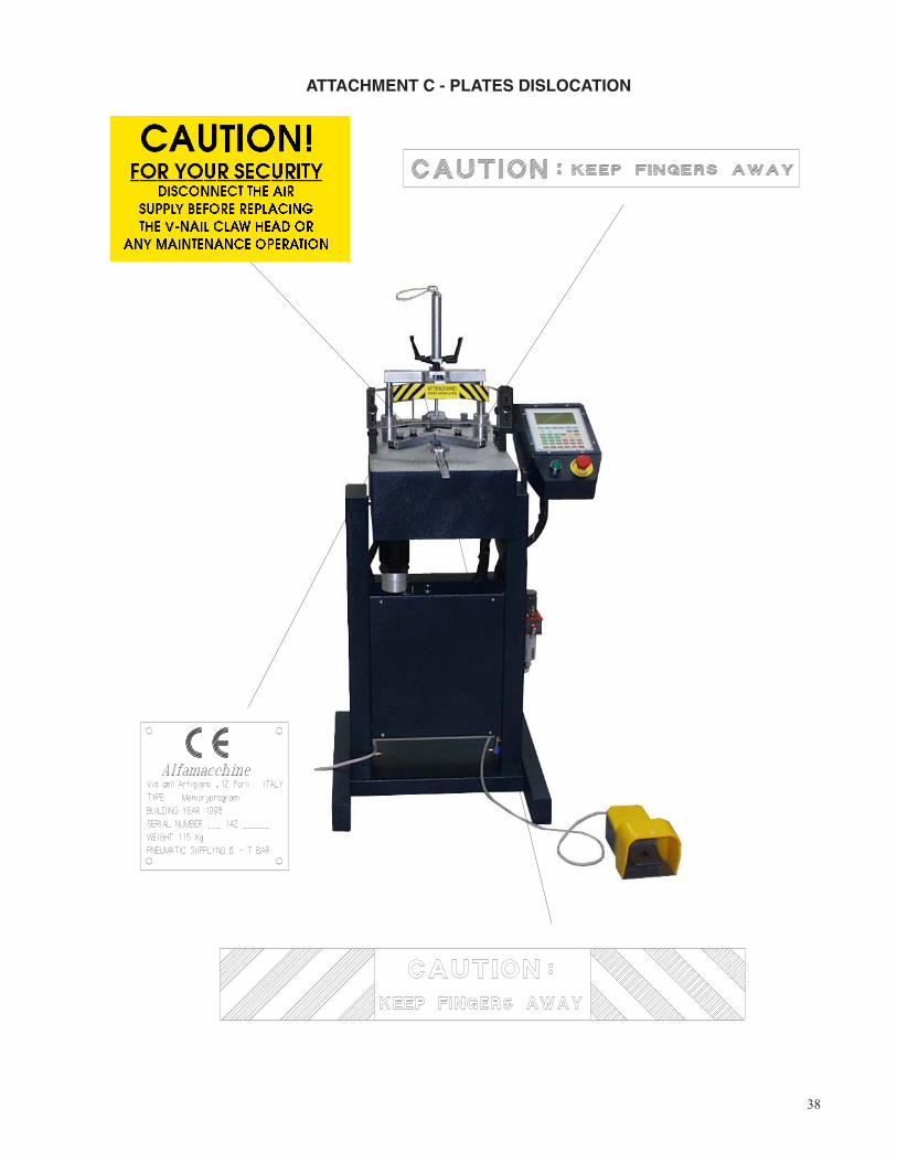
ATTACHMENT C - PLATES DISLOCATION
39
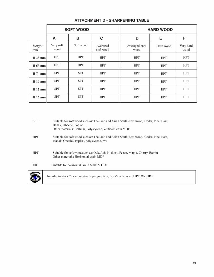
ATTACHMENT D - SHARPENING TABLE
SPT Suitable for soft wood such as: Thailand and Asian South-East wood, Cedar, Pine, Bass, Banak, Obeche, Poplar Other materials: Cellular, Polystyrene, Vertical Grain MDF
HPT Suitable for soft wood such as: Thailand and Asian South-East wood, Cedar, Pine, Bass, Banak, Obeche, Poplar , polystyrene, pvc
HPT Suitable for soft wood such as: Oak, Ash, Hickory, Pecan, Maple, Cherry, RaminOther materials: Horizontal grain MDF
SOFT WOOD HARD WOOD
A B C D E F
Heightmm
H 3* mm
H 5* mm
H 7 mm
H 10 mm
H 12 mm
H 15 mm
Very softwood
HPT
HPT
SPT
SPT
SPT
SPT
Soft wood
HPT
HPT
SPT
SPT
SPT
SPT
Averagedsoft wood
HPT
HPT
HPT
HPT
HPT
HPT
Averaged hardwood
HPT
HPT
HPT
HPT
HPT
HPT
Hard wood
HPT
HPT
HPT
HPT
HPT
HPT
Very hardwood
HPT
HPT
HPT
HPT
HPT
HPT
In order to stack 2 or more V-nails per junction, use V-nails coded HPT OR HDF
HDF Suitable for horizontal Grain MDF & HDF
40
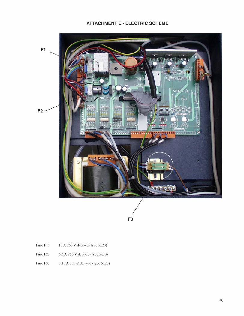
ATTACHMENT E - ELECTRIC SCHEME
F1
F2
F3
Fuse F1: 10 A 250 V delayed (type 5x20)
Fuse F2: 6,3 A 250 V delayed (type 5x20)
Fuse F3: 3,15 A 250 V delayed (type 5x20)
41
42
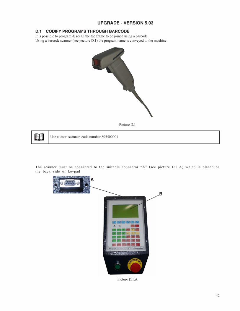
UPGRADE - VERSION 5.03
D.1 CODIFY PROGRAMS THROUGH BARCODEIt is possible to program & recall the the frame to be joined using a barcode.Using a barcode scanner (see pecture D.1) the program name is conveyed to the machine
Picture D.1
Use a laser scanner, code number 805500001
The scanner must be connected to the suitable connector “A” (see picture D.1.A) which is placed onthe back side of keypad
Picture D.1.A
A
B
43
In order to use the scanner, operate as follows:- select with the scanner the code which corresponds to the frame to be joined- the machine positions itself on the selected program- press “EXE” to execute the working cycle
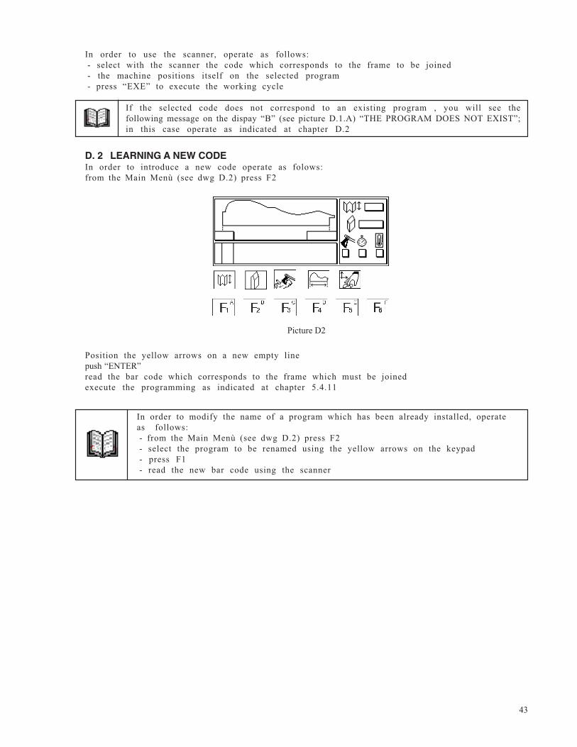
D. 2 LEARNING A NEW CODEIn order to introduce a new code operate as folows:from the Main Menù (see dwg D.2) press F2
Picture D2
Position the yellow arrows on a new empty linepush “ENTER”read the bar code which corresponds to the frame which must be joinedexecute the programming as indicated at chapter 5.4.11
In order to modify the name of a program which has been already installed, operateas follows:- from the Main Menù (see dwg D.2) press F2- select the program to be renamed using the yellow arrows on the keypad- press F1- read the new bar code using the scanner
If the selected code does not correspond to an existing program , you will see thefollowing message on the dispay “B” (see picture D.1.A) “THE PROGRAM DOES NOT EXIST”;in this case operate as indicated at chapter D.2
44
Upgrade version 5.5.0 (February 1999)
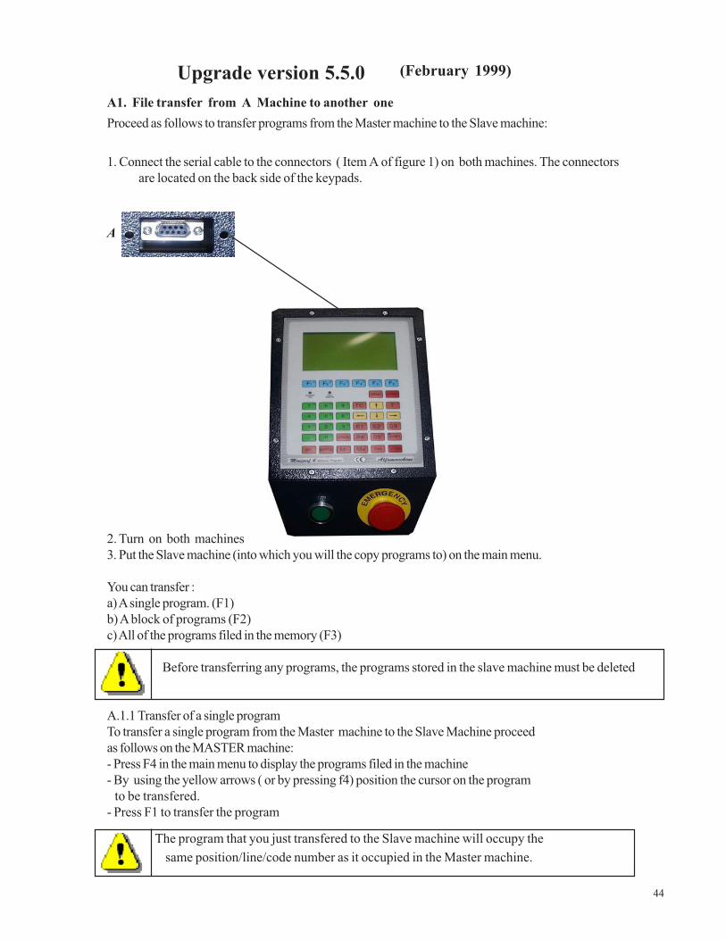
A1. File transfer from A Machine to another oneProceed as follows to transfer programs from the Master machine to the Slave machine:
1. Connect the serial cable to the connectors ( Item A of figure 1) on both machines. The connectorsare located on the back side of the keypads.
A
2. Turn on both machines3. Put the Slave machine (into which you will the copy programs to) on the main menu.
You can transfer :a) A single program. (F1)b) A block of programs (F2)c) All of the programs filed in the memory (F3)
Before transferring any programs, the programs stored in the slave machine must be deleted
A.1.1 Transfer of a single programTo transfer a single program from the Master machine to the Slave Machine proceedas follows on the MASTER machine:- Press F4 in the main menu to display the programs filed in the machine- By using the yellow arrows ( or by pressing f4) position the cursor on the program to be transfered.- Press F1 to transfer the program
The program that you just transfered to the Slave machine will occupy the same position/line/code number as it occupied in the Master machine.
45
A.1.2 Transfer of a bulk of programsTo transfer a bulk of programs from the Master machine to the Slave machine, proceed as follows on the
MASTER machine:- Press F4- Use the yellow arrow keys to position the cursor on the 1st program to be transfered.- Press F2- Type in the last code number of the programs to be transfered, then press enter- Type in the 1st code/line number on the Slave machine where you want to place the selected programs- Press Enter to confirm the transmission
A.1.3 Transfering all the programs stored in the Master machineTo transfer all of the programs from the Master machine to the Slave machine, proceed as follows:- Press the F4 key- Press the F3 key
The programs will be input into the Slave machine in the same position they had in the master machine. They will replace any programs present in the Slave machine before the transfer.