Embed Size (px)
Citation preview
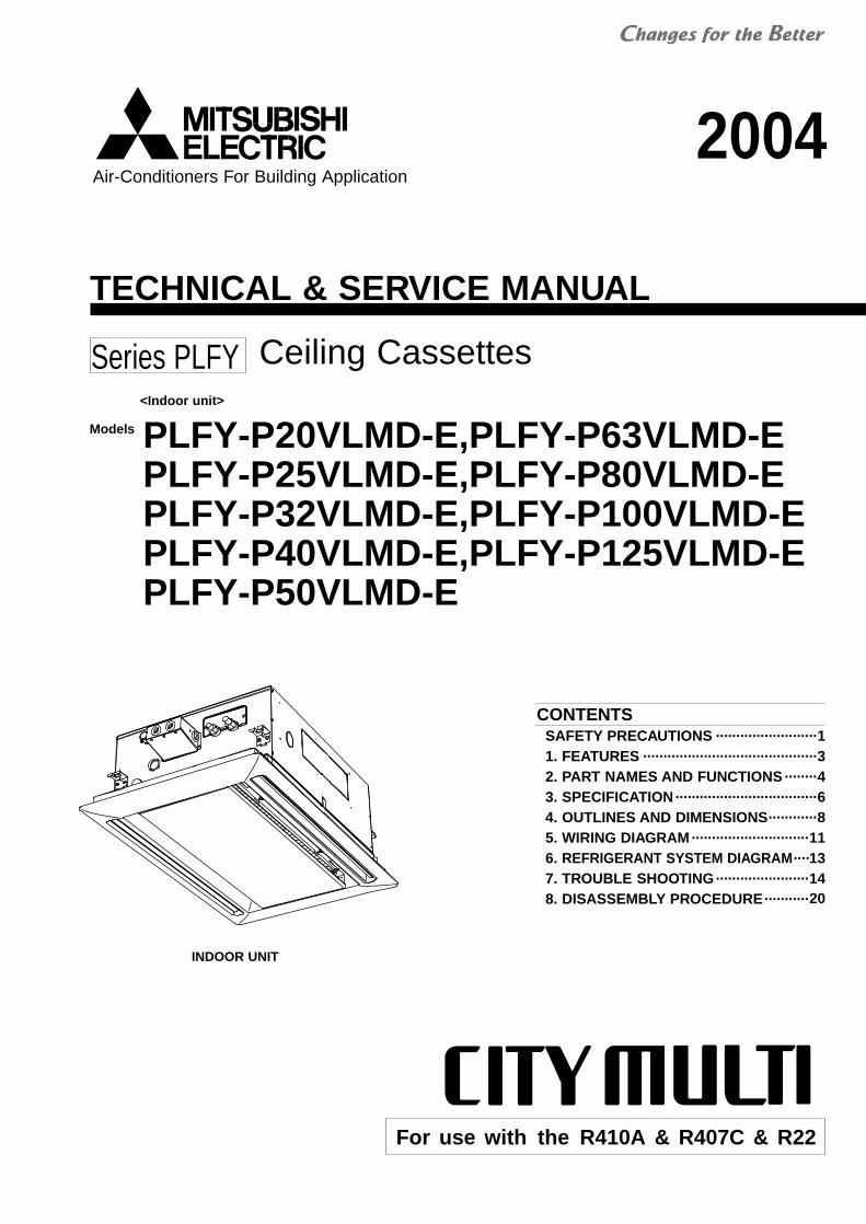
TECHNICAL & SERVICE MANUAL
Air-Conditioners For Building Application
<Indoor unit>
2004
Models
Ceiling CassettesSeries PLFY
For use with the R410A & R407C & R22
PLFY-P20VLMD-E,PLFY-P63VLMD-EPLFY-P25VLMD-E,PLFY-P80VLMD-EPLFY-P32VLMD-E,PLFY-P100VLMD-EPLFY-P40VLMD-E,PLFY-P125VLMD-EPLFY-P50VLMD-E
INDOOR UNIT
CONTENTSSAFETY PRECAUTIONS ·························11. FEATURES ···········································32. PART NAMES AND FUNCTIONS ········43. SPECIFICATION···································64. OUTLINES AND DIMENSIONS············85. WIRING DIAGRAM ·····························116. REFRIGERANT SYSTEM DIAGRAM 13····7. TROUBLE SHOOTING·······················148. DISASSEMBLY PROCEDURE···········20

SAFETY PRECAUTIONS
and install the unit at the specified place.- Improper installation may cause the unit to topple and result in
injury.• Always use an air cleaner, humidifier, electric heater, and other
accessories specified by Mitsubishi Electric.- Ask an authorized technician to install the accessories. Improper
installation by the user may result in water leakage, electric shock,or fire.
• Never repair the unit. If the air conditioner must be repaired,consult the dealer.- If the unit is repaired improperly, water leakage, electric shock, or
fire may result.• Do not touch the heat exchanger fins.
- Improper handling may result in injury.• If refrigerant gas leaks during installation work, ventilate the
room.- If the refrigerant gas comes into contact with a flame, poisonous
gases will be released.• Install the air conditioner according to this Installation Manual.
- If the unit is installed improperly, water leakage, electric shock, orfire may result.
• Have all electric work done by a licensed electrician accordingto “Electric Facility Engineering Standard” and “Interior WireRegulations”and the instructions given in this manual and al-ways use a special circuit.- If the power source capacity is inadequate or electric work is per-
formed improperly, electric shock and fire may result.
• Securely install the cover of control box and the panel.- If the cover and panel are not installed properly,dust or water may
enter the outdoor unit and fire or electric shock may result.• When installing and moving the air conditioner to another site,
do not charge the it with a refrigerant different from the refrig-erant specified on the unit.- If a different refrigerant or air is mixed with the original refrigerant,
the refrigerant cycle may malfunction and the unit may be dam-aged.
• If the air conditioner is installed in a small room, measuresmust be taken to prevent the refrigerant concentration fromexceeding the safety limit even if the refrigerant should leak.- Consult the dealer regarding the appropriate measures to pre-
vent the safety limit from being exceeded. Should the refrigerantleak and cause the safety limit to be exceeded, hazards due tolack of oxygen in the room could result.
• When moving and reinstalling the air conditioner, consult thedealer or an authorized technician.- If the air conditioner is installed improperly, water leakage, elec-
tric shock, or fire may result.• After completing installation work, make sure that refrigerant
gas is not leaking.- If the refrigerant gas leaks and is exposed to a fan heater, stove,
oven, or other heat source, it may generate noxious gases.• Do not reconstruct or change the settings of the protection
devices.- If the pressure switch, thermal switch, or other protection device
is shorted and operated forcibly, or parts other than those specifiedby Mitsubishi Electric are used, fire or explosion may result.
1. Before installation and electric work
s Before installing the unit, make sure you read all the“Safety precautions”.
s The “Safety precautions” provide very importantpoints regarding safety. Make sure you follow them.
s This equipment may cause the adverse effect on thesame supply system.
s Please report to or take consent by the supply au-thority before connection to the system.
Symbols used in the text
Warning:Describes precautions that should be observed to prevent dangerof injury or death to the user.
Caution:Describes precautions that should be observed to prevent damageto the unit.
Symbols used in the illustrations
: Indicates an action that must be avoided.
: Indicates that important instructions must be followed.
: Indicates a part which must be grounded.
: Indicates that caution should be taken with rotating parts. (This
symbol is displayed on the main unit label.) <Color: Yellow>
: Beware of electric shock (This symbol is displayed on the main
unit label.) <Color: Yellow>
Warning:Carefully read the labels affixed to the main unit.
Warning:• Ask the dealer or an authorized technician to install the air con-
ditioner.- Improper installation by the user may result in water leakage, elec-
tric shock, or fire.• Install the air unit at a place that can withstand its weight.
- Inadequate strength may cause the unit to fall down, resulting ininjuries.
• Use the specified cables for wiring. Make the connections se-curely so that the outside force of the cable is not applied to theterminals.- Inadequate connection and fastening may generate heat and cause
a fire.• Prepare for typhoons and other strong winds and earthquakes
• Keep the electric parts away from water (washing water etc.).- It might result in electric shock, catching fire or smoke.
• To dispose of this product, consult your dealer.• Do not use a leak detection additive.
1

2. Precautions for devices that use
Caution:• Do not use the existing refrigerant piping.
- The old refrigerant and refrigerator oil in the existing piping con-tains a large amount of chlorine which may cause the refrigeratoroil of the new unit to deteriorate.
• Use refrigerant piping made of C1220 (Cu-DHP) phosphorusdeoxidized copper as specified in the *JIS H3300 “Copper andcopper alloy seamless pipes and tubes”. In addition, be surethat the inner and outer surfaces of the pipes are clean andfree of hazardous sulphur, oxides, dust/dirt, shaving particles,oils, moisture, or any other contaminant.- Contaminants on the inside of the refrigerant piping may cause
the refrigerant residual oil to deteriorate.*JIS: Japanese Industrial Standard
• Store the piping to be used during installation indoors and keepboth ends of the piping sealed until just before brazing. (Storeelbows and other joints in a plastic bag.)- If dust, dirt, or water enters the refrigerant cycle, deterioration of
the oil and compressor trouble may result.• Use ester oil, ether oil or alkylbenzene (small amount) as the
refrigerator oil to coat flares and flange connections.- The refrigerator oil will degrade if it is mixed with a large amount of
mineral oil.• Use liquid refrigerant to fill the system.
- If gas refrigerant is used to seal the system, the composition ofthe refrigerant in the cylinder will change and performance maydrop.
• Do not use a refrig- If another refrigerant (R22, etc.) is used, the chlorine in the refrig-
erant may cause the refrigerator oil to deteriorate.• Use a vacuum pump with a reverse flow check valve..
- The vacuum pump oil may flow back into the refrigerant cycle andcause the refrigerator oil to deteriorate.
• Do not use the following tools that are used with conventionalrefrigerants.(Gauge manifold, charge hose, gas leak detector, reverse flowcheck valve, refrigerant charge base, vacuum gauge, refriger-ant recovery equipment)- If the conventional refrigerant and refrigerator oil are mixed in the
• Do not use a charging cylinder.- Using a charging cylinder may cause the refrigerant to deteriorate.
• Be especially careful when managing the tools.- If dust, dirt, or water gets in the refrigerant cycle, the refrigerant
may deteriorate.
R410A or R407C refrigerant
erant other than R410A or R407C.
R410A or R407C, the refrigerant may deteriorated.- If
deteriorate.water is mixed in the R410A or R407C, the refrigerator oil may
- Since R410A or R407C does not contain any chlorine, gas leak detectors for conventional refrigerants will not react to it.
2

PLFY-P20VLMD-E
PLFY-P25VLMD-E
PLFY-P32VLMD-E
PLFY-P40VLMD-E
PLFY-P50VLMD-E
PLFY-P63VLMD-E
2.2 / 2.5
2.8 / 3.2
3.6 / 4.0
4.5 / 5.0
5.6 / 6.3
PLFY-P80VLMD-E 9.0 / 10.0
PLFY-P100VLMD-E 11.2 / 12.5
PLFY-P125VLMD-E 14.0 / 16.0
7.1 / 8.0
FEATURES1
Indoor unit
Ceiling CassettesSeries PLFY
ModelsCooling capacity/Heating capacity
kW
3

PART NAMES AND FUNCTIONS2
Indoor (Main) Unit
Air inletSucks the ambient air in.
Long-life filterRemoves the sucked-in dust and dirt.Since the long-life filter is used as an airfilter, it should be cleaned at the begin-ning of air-cooling and heating seasons.(During seasons with large amounts ofdust and dirt, more frequent cleaning arerecommended.)
AutovaneDisperses the airflow up and down andadjusts the angle of the airflow.
Remote controller
[Operation buttons]
[PAR-20MAA] Once the controls are set, the same operation mode can
be repeated by simply pressing the ON/OFF button.
PAR-20MAA
ON/OFF
CENTRALLY CONTROLLED
ERROR CODE
CLOCK
ON OFF
˚C
CHECK
CHECK MODEFILTER
TEST RUNFUNCTION
˚C1Hr.
NOT AVAILABLESTAND BY DEFROST
FILTER
CHECK TEST
TEMP.
TIMER SET
1
2
3
4 5 6 8 7 9
0
C
A
B
1 [Room temperature adjustment] Button2 [Timer/continuous] Button3 [Selecting operation] Button4 [Time selection] Button
[Time-setting] Button5 [Louver] Button6 [Fan speed adjustment] Button
7 [Up/down airflow direction] Button8 [Ventilation] Button9 [Checking/built-in] Button0 [Test run] ButtonA [Filter] ButtonB [ON/OFF] ButtonC Position of built-in room temperature
•Never expose the remote controller to direct sunlight. Doing so can result in the erroneous measure-ment of room temperature.
•Never place any obstacle around the lower right-hand section of the remote controller. Doing so canresult in the erroneous measurement of room temperature.
4

[Display]
ON/OFF
CENTRALLY CONTROLLED
ERROR CODE
CLOCK
ON OFF
˚C
CHECK
CHECK MODEFILTER
TEST RUNFUNCTION
˚C1Hr.
NOT AVAILABLESTAND BY DEFROST
TEMP.
ABCD
E
F
H IKLJ
M
P
N
O
R
SQTU
G
A Current time/TimerB Centralized controlC Timer OND Abnormality occursE Operation mode: COOL, DRY, AUTO, FAN, HEATF Preparing for Heating modeG Defrost modeH Set temperatureI Power ONJ LouverK Not available functionL VentilationM Function setting modeN Test run modeO Error check modeP Filter signQ Set effective for 1 hr.R Sensor positionS Room temperatureT AirflowU Fan speed
5

3 SPECIFICATION
3-1. Specification
6
Note:
3 The figure in < > indicates panel's
1 Cooling/Heating capacity indicates the maximum value at operation under the following condition.Cooling : Indoor 27˚CDB/19˚CWB,Outdoor 35˚CDBHeating : Indoor 20˚CDB,Outdoor 7˚CDB/6˚CWB
2 Cooling capacity indicates the maximum value at operation under the following condition.Cooling : Indoor 27˚CDB/19.5˚CWB,Outdoor 35˚CDB (WR2: water 30˚C)
4 It is measured in anechoic room.
PLFY-P20VLMD-E PLFY-P25VLMD-E PLFY-P32VLMD-E PLFY-P40VLMD-E~ 220-240V 50Hz / ~ 220-230V 60HzPower source
kcal/h
kWCooling capacity
1
2 1
3
kWkWCooling
Heating
Cooling
Heating
kW
A
A
mm
mm
mm
kg
m3/min
Pa
kW
mm
mm
dB(A)
dB(A)
Heating capacity
Powerconsumption
Current
External finish(Munsel No.)
Dimension 3
Height
Width
Depth
Net weight
Heat exchanger
Fan
Type
External static pressure
MotorOutput
Type
Air filter
Refrigerant pipe dimension
Gas(Flare)
Liquid(Flare)
Drain pipe dimension
Unit: Galvanizing Decoration Panel: ABS (0.7Y 8.59/0.97) Service Panel: Galvanizing (0.7Y 8.59/0.97)
290 <20>776 <1080>
634 <710>
23 <6.5>
Cross fin
Turbo fan1
Single phase induction motor
PP honeycomb fabric (long life filter)ø 12.7
ø 6.35
Unit drain pipe I.D.32 (1-1/4inch)
6.5-8.0-9.5 7.0-8.5-10.5
0
0.015
24 <6.5>
Airflow rate (Lo-Mid-Hi)
Noise level (Lo-Mid-Hi) 4
220V,240V
230V
2.2
2,000
2.5
0.072 / 0.075
0.065 / 0.069
0.36 / 0.37
0.30 / 0.32
2.8
2,500
3.2
0.072 / 0.075
0.065 / 0.069
0.36 / 0.37
0.30 / 0.32
3.6
3,150
4.0
0.072 / 0.075
0.065 / 0.069
0.36 / 0.37
0.30 / 0.32
4.5
4,000
5.0
0.081 / 0.085
0.074 / 0.079
0.40 / 0.42
0.34 / 0.37
27-30-33
28-31-34 30-34-37
PLFY-P63VLMD-E PLFY-P80VLMD-E PLFY-P100VLMD-E PLFY-P125VLMD-E~ 220-240V 50Hz / ~ 220-230V 60HzPower source
kcal/h
kWCooling capacity
1
2 1
3
kWkWCooling
Heating
Cooling
Heating
kW
A
A
mm
mm
mm
kg
m3/min
Pa
kW
mm
mm
dB(A)
dB(A)
Heating capacity
Powerconsumption
Current
External finish(Munsel No.)
Dimension 3
Height
Width
Depth
Net weight
Heat exchanger
Fan
Type
External static pressure
MotorOutput
Type
Air filter
Refrigerant pipe dimension
Gas(Flare)
Liquid(Flare)
Drain pipe dimension
Unit: Galvanizing Decoration Panel: ABS (0.7Y 8.59/0.97) Service Panel: Galvanizing (0.7Y 8.59/0.97)
634 <710>
290 <20> 1446 <1750> 1708 <2010>
606 <710>
28 <7.5> 44 <12.5> 47 <12.5> 56 <13.0>
Cross fin
Turbo fan1 Turbo fan2 Sirocco fan4
Single phase induction motor
Synthetic fiber unwovencloth filter (long life)
ø 15.88
ø 9.52
Unit drain pipe I.D.32 (1-1/4inch)
10.0-13.0-15.524.0-27.0-30.0-33.0(Lo-Mid2-Mid1-Hi)
17.5-21.0-25.015.5-18.5-22.0
0
0.020 0.020 (at 240V) 0.030 (at 240V) 0.0782(at 240V)
Airflow rate (Lo-Mid-Hi)
Noise level (Lo-Mid-Hi) 4
220V,240V
230V
7.1
6,300
8.0
0.101 / 0.105
0.094 / 0.099
0.49 / 0.51
0.43 / 0.46
9.0
8,000
10.0
0.147 / 0.156
0.140 / 0.150
0.72 / 0.74
0.66 / 0.69
11.2
10,000
12.5
0.157 / 0.186
0.150 / 0.180
0.75 / 0.88
0.69 / 0.83
14.0
12,500
16.0
0.28 / 0.28
0.27 / 0.27
1.35 / 1.35
1.33 / 1.33
33-36-39
34-37-40
PLFY-P50VLMD-E
946 <1250>
27 <7.5>
PP honeycomb fabric (long life filter)
9.0-11.0-12.5
5.6
5,000
6.3
0.082 / 0.086
0.075 / 0.080
0.41 / 0.43
0.35 / 0.38
31-34-37
32-35-38
32-37-39
33-38-40 37-41-4340-42-44-46
(Lo-Mid2-Mid1-Hi)
ø 15.88 (R410A)ø 19.05 (R22,R407C)
29-33-36
ø 12.7 (R410A)ø 15.88 (R22,R407C)
ø 6.35 (R410A)ø 9.52 (R22,R407C)
36-39-42

1.7µFx 440V
1.5µFx 440V
2.2µFx 440V
1.5µFx 440V
2.0µFx 440V
5.0µFx 440V
LEV
C1 1.3µF x 440V
MF1
-
PLFY-P20VLMD-E
PLFY-P25VLMD-E
PLFY-P32VLMD-E
PLFY-P40VLMD-E
PLFY-P50VLMD-E
PLFY-P63VLMD-E
3-2. Electrical parts specifications
Model
Partsname
Tranrsformer T (Primary) 220-240V 50Hz, 220-230V 60Hz (Secondry) 23.2V 1.1A
(Primary)50/60Hz
220-240V(Secondry)18.4V 1.7A
Resistance 0°C/15kΩ, 10°C/9.6kΩ, 20°C/6.3kΩ,25°C/5.4kΩ, 30°C/4.3kΩ, 40°C/3.0kΩ
Resistance 0°C/15kΩ, 10°C/9.6kΩ, 20°C/6.3kΩ,25°C/5.4kΩ, 30°C/4.3kΩ, 40°C/3.0kΩ
Resistance 0°C/15kΩ, 10°C/9.6kΩ, 20°C/6.3kΩ,25°C/5.4kΩ, 30°C/4.3kΩ, 40°C/3.0kΩ
TH21
TH22
Gas pipethermistor
F901 250V 6.3A
MV
DP
Drain sensor DS
TB2
TB5TB15
Fuse(Indoor
controller board)
Power supplyterminal bed
Transmissionterminal bed
PLFY-P80VLMD-E
PLFY-P100VLMD-E
PLFY-P125VLMD-E
OFF 145±8°CON 88±15°C
DC12V Stepping motor
INPUT 6.4/5.5W400cm3/min
INPUT8/7.5W
400cm3/min
Resistance 0°C/6.0kΩ, 10°C/3.9kΩ, 20°C/2.6kΩ,25°C/2.2kΩ, 30°C/1.8kΩ, 40°C/1.3kΩ
DC12V Stepping motor drive port dimension ø 3.2 (0~2000pulse)
(L,N, ) 330V 30A
(M1,M2,S),(1,2) 300V 10A
Roomtemperaturethermistor
Fan motor(with Inner-
thermostat)
6-poleOUTPUT 15W
6-poleOUTPUT
30W
4-poleOUTPUT
78W
6-poleOUTPUT 20W
Symbol
TH23
Inner-thermostat
(Fan motor)
Liquid pipethermistor
Fan motorcapacitor
Drain-upmechanism
Linear expansion valve
Vane motor
OFF130˚C±5˚C
ON90˚C±20˚C
DC12V Stepping motor driveport dimension ø 5.2
0~1800pulse <at R410A outdoor unit>0~2000pulse <at the other outdoor unit>
0~1800pulse <at R410A outdoor unit>0~2000pulse <at the other outdoor unit>
7

4 OUTLINES AND DIMENSIONS
PLFY-P20·25·32·40·50·63·80·100VLMD-EUnit : mm
8
170m
m ±
5m
m(A
ctua
l Len
gth)
300m
m o
r le
ss
583mmMAX
73202
222
190
4-ø2
.9 M
ount
ing
hole
Fres
h ai
r in
take
240
x45
knoc
k ou
t hol
e
240
197
45216
710
AS
tand
ard
cent
er p
anel
Term
inal
bed
(Tra
nsm
issi
on)
Term
inal
bed
(Pow
er s
ourc
e)
48
670
48
70146
507
634
574
108
D(L
iftin
g B
olt P
itch)
108
B
Term
inal
box
Air
filte
r
Wat
er fi
lling
por
tD
rain
hol
e
3
2
1
290
45
20
68
20
20
68
More Than 350
670
190
146
497
634
122
266
60
574
(Lift
ing
Bol
t Pitc
h)
70
3
3622
2927
H(G
as)
22
H(L
iqui
d)
17
CM
P-6
3VLW
-B
CM
P-4
0VLW
-B38
877
682
410
4010
80
473
994
946
1210
1250
ED
CB
A
PLF
Y-P
63V
LMD
-EP
LFY
-P50
VLM
D-E
PLF
Y-P
40V
LMD
-EP
LFY
-P32
VLM
D-E
PLF
Y-P
25V
LMD
-EP
LFY
-P20
VLM
D-EMod
el
217.
52
=435F
6G
PLF
Y-P
100V
LMD
-EP
LFY
-P80
VLM
D-E
1018
8.5
4=7
5414
9472
314
4617
1017
50C
MP
-100
VLW
-B
H
Not
e:1.
Use
M10
scr
ew fo
r th
e lif
ing
bolt
(fie
ld s
uppl
y).
2.It
is a
vaila
ble
to c
onne
ct th
e br
anch
duc
t on
right
and
left
side
bot
h.3.
On
Mod
el :5
0, 1
00, y
ou w
ould
use
flar
e nu
t pac
ked
with
the
Indo
or
Uni
t, w
hen
conn
nect
ing
the
Out
door
Uni
t for
R40
7C, R
22.
4.In
ord
er to
incr
ease
the
stre
ngth
of t
he fl
are
nut,
the
size
of s
ome
of th
em h
as b
een
incr
ease
d.
<fla
re>
Mod
elG
as p
ipe:
LPø1
2.7
20·2
5·32
·40
Liqu
id p
ipe:
HP
ø6.3
5 M
odel
Gas
pip
e:LP
ø12.
7<R
410A
out
door
uni
t>50
ø15.
88<
The
oth
er o
utdo
or u
nit>
Li
quid
pip
e:H
Pø6
.35<
R41
0A o
utdo
or u
nit>
ø9.5
2<T
he o
ther
out
door
uni
t> M
odel
Gas
pip
e:LP
ø15.
88
63·8
0Li
quid
pip
e:H
Pø9
.52
Mod
elG
as p
ipe:
LPø1
5.88
<R
410A
out
door
uni
t>10
0ø1
9.05
<T
he o
ther
out
door
uni
t>Li
quid
pip
e:H
Pø9
.52
Dra
in h
ose
V
P-2
5<fle
xibl
e jo
int>
(ac
cess
ory)
······
·· 1
······
·· 2
······
·· 1
······
·· 2
······
·· 1
······
·· 2
······
·· 1
······
·· 2
······
·· 3
G-ø
2.9
Mou
ntin
g ho
le
Bra
nch
duct
Fx1
10 k
nock
out
hol
e (b
oth
side
)(N
ote:
2)
Con
trol
box
2020
B
E
C
D(L
iftin
g bo
lt pi
tch)
221
34 159
52 110
F
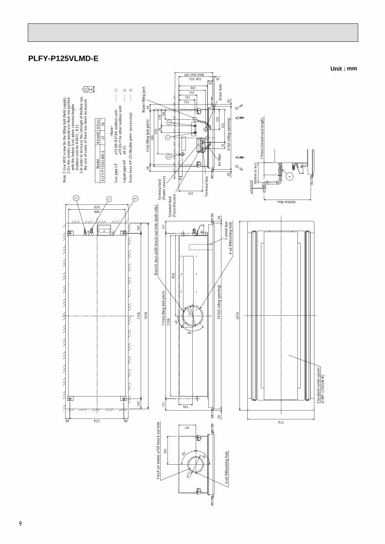
PLFY-P125VLMD-EUnit : mm
A
3
31
2
Wat
er fi
lling
por
t
2 1 3
Air
filte
r
20338~353
4-ø2
.8M
ount
ing
hole
Sta
ndar
d ce
nter
pan
el(C
MP
-125
VLW
-B)
Bra
nch
duct
ø20
0 kn
ock
out h
ole
(bot
h si
de)
4-ø2
.9M
ount
ing
hole
Fres
h ai
r in
take
ø15
0 kn
ock
out h
ole
90˚
ø224
45˚
90˚
ø172
90˚303
170m
m±5
mm
(Act
ual l
engt
h)
600mm Max
300m
m o
r le
ss
45
More than 350
155
255
127
127
107
574
1970
670
48 48
107
1756
6868
574(
Lifti
ng b
olt p
itch)
192
1970
(Cei
ling
open
ing)
670(
Cei
ling
open
ing)
2020
710
2010
2020
290
606
145
856
1708
1756
(Lift
ing
bolt
pitc
h)
181
235
Dra
in h
ole
222
Con
trol
box
Term
inal
box
Term
inal
bed
(Pow
er s
ourc
e)
7033
3
38
106
476 70
178
606
Term
inal
bed
(Tra
nsm
issi
on)
Not
e:1.
Use
M10
scr
ew fo
r th
e lif
ting
bolt
(fie
ld s
uppl
y).
2.O
n th
is m
odel
, you
wou
ld u
se fl
are
nut p
acke
d w
ith th
e In
door
Uni
t, w
hen
conn
nect
ingt
he
Out
door
Uni
t for
R40
7C, R
22.
3.In
ord
er to
incr
ease
the
stre
ngth
of t
hefla
re n
ut,
the
size
of s
ome
of th
em h
as b
een
incr
ease
d.
36A
(Gas
)A
(Liq
uid)
22P
LFY-
P12
5VLM
D-E
Mod
el
<fla
re>
Gas
pip
e:LP
ø15.
88<
R41
0A o
utdo
or u
nit>
ø19.
05<
The
oth
er o
utdo
or u
nit>
Liqu
id p
ipe:
HP
ø9.5
2 D
rain
hos
e V
P-2
5<fle
xibl
e jo
int>
(ac
cess
ory)
······
·· 1
······
·· 2
······
·· 3
9

10
PLFY-P20·25·32·40·50·63·80·100VLMD-E with OA duct flangeUnit : mm
52
34
110
159
E
20
221
Con
trol
Box
G-ø
2.9
Mou
ntin
g ho
le
both
sid
e 206
241
138
243
103
D(L
iftin
g B
olt P
itch)
C B20
F
Bra
nch
duct
Fx1
10 k
nock
out
hol
e (b
oth
side
)(N
ote:
2)
45˚
Fres
h ai
r in
take
kno
ck o
ut d
imen
sion
Fres
h ai
r in
take
ø15
0 kn
ock
out h
ole
4-ø2
.9 M
ount
ing
hole
ø1
72
ø150
90˚
103
128
B
108
D(L
iftin
g B
olt P
itch)
108
574
634
507
146 70
48
670
48
Term
inal
bed
(Pow
er s
ourc
e)
Term
inal
bed
(Tra
nsm
issi
on)
128
24125
618
9
Term
inal
box
Air
filte
r
Wat
er fi
lling
por
tD
rain
hol
e
3
2
1
290
45
20
68
20
20
68
More Than 350
670
190
146
497
634
122
266
60
574
(Lift
ing
Bol
t Pitc
h)
70
170m
m
5m
m(A
ctua
l Len
gth)
300m
m o
r le
ss
583mmMAX
710
AS
tand
ard
cent
er p
anel
336
22
2927
H(G
as)
22
H(L
iqui
d)
17
CM
P-6
3VLW
-B
CM
P-4
0VLW
-B38
877
682
410
4010
80
473
994
946
1210
1250
ED
CB
A
PLF
Y-P
63V
LMD
-EP
LFY
-P50
VLM
D-E
PLF
Y-P
40V
LMD
-EP
LFY
-P32
VLM
D-E
PLF
Y-P
25V
LMD
-EP
LFY
-P20
VLM
D-EMod
el
217.
52
=435F
6G
PLF
Y-P
100V
LMD
-EP
LFY
-P80
VLM
D-E
1018
8.5
4=7
5414
9472
314
4617
1017
50C
MP
-100
VLW
-B
H
Not
e:1.
Use
M10
scr
ew fo
r th
e lif
ing
bolt
(fie
ld s
uppl
y).
2.It
is a
vaila
ble
to c
onne
ct th
e br
anch
duc
t on
right
and
left
side
bot
h.3.
On
Mod
el :5
0, 1
00, y
ou w
ould
use
flar
e nu
t pac
ked
with
the
Indo
or
Uni
t, w
hen
conn
nect
ing
the
Out
door
Uni
t for
R40
7C, R
22.
4.In
ord
er to
incr
ease
the
stre
ngth
of t
he fl
are
nut,
the
size
of s
ome
of th
em h
as b
een
incr
ease
d.
<fla
re>
Mod
elG
as p
ipe:
LPø1
2.7
20·2
5·32
·40
Liqu
id p
ipe:
HP
ø6.3
5 M
odel
Gas
pip
e:LP
ø12.
7<R
410A
out
door
uni
t>50
ø15.
88<
The
oth
er o
utdo
or u
nit>
Li
quid
pip
e:H
Pø6
.35<
R41
0A o
utdo
or u
nit>
ø9.5
2<T
he o
ther
out
door
uni
t> M
odel
Gas
pip
e:LP
ø15.
88
63·8
0Li
quid
pip
e:H
Pø9
.52
Mod
elG
as p
ipe:
LPø1
5.88
<R
410A
out
door
uni
t>10
0ø1
9.05
<T
he o
ther
out
door
uni
t>Li
quid
pip
e:H
Pø9
.52
Dra
in h
ose
V
P-2
5<fle
xibl
e jo
int>
(ac
cess
ory)
······
·· 1
······
·· 2
······
·· 1
······
·· 2
······
·· 1
······
·· 2
······
·· 1
······
·· 2
······
·· 3

5 WIRING DIAGRAM
PLFY-P20·25·32·40·50·63·80·100VLMD-E
11
DE
CO
RAT
ION
PA
NE
L
T2
T1
T7T6
T5T4
T3
BR
EA
KE
R (1
6A)
FUS
E (1
6A)
TO N
EX
T IN
DO
OR
UN
IT
PU
LL B
OX
( TR
AN
SM
ISS
ION
TE
RM
INA
L B
ED
)
SY
MB
OL
EX
PLA
NAT
ION
( TR
AN
SM
ISS
ION
TE
RM
INA
L B
ED
)
TO M
A R
EM
OTE
CO
NTR
OLL
ER
TO O
UTD
OO
R U
NIT
BC
CO
NTR
OLL
ER
RE
MO
TE C
ON
TRO
LLE
R
TB2
MV 3
41
52
41
52
3
MV C
N7V
12
34
5
79
S(SH
IELD
)TB5
PEN
CN2M
M1
M2
12
TB15 2 1
CN3A
13
CN
D
13
5
DS
A1
ZN
R1
CN
90
ZNR9
01X0
4X0
1X0
6X0
7X0
5
C
MF4
51
23
91
35
7
LEV
23
113
CN
P
T
31C
NT
31
CN
3T
DP
65
43
21
CN
60
13
CN
31
DSTH
23
12
CN
29
TH22
12
CN
21
TH21
21
CN
20
01
2 3
45
6
78
91
6
2
7
3
8
4
90 5
01
23 4 5 6
78
9
A
BCDE
F
SW
11(1
st d
igit)
SW
12(2
nd d
igit)
SW
14(C
onne
ction
No.)
INS
IDE
SE
CTI
ON
OF
CO
NTR
OL
BO
X
L
SW
2
SW
5
SW
3S
W4
SW
1S
W7
PO
WE
R S
UP
PLY
~22
0V-2
40V
50H
z22
0V-2
30V
60H
zF
or te
st o
f pum
p ou
t(a
fter
conf
irm
dra
in p
ump
out,
take
this
con
nect
or o
ff.)
CN
27C
N41
CN
52
CN
51C
N32
SW
8
I.B
Aux.
rela
y (D
rain
pum
p)
Term
inal
NA
ME
NA
ME
SY
MB
OL
MF C I.B TB2
TB5
TB15
F901
ZNR1
,ZNR
901
T DP
LEV
DS
MV
SY
MB
OL
CN
27C
N32
CN
41C
N51
CN
52X
01X
04X
05X
06X
07TH
21TH
22TH
23
SY
MB
OL
SW
11S
W12
SW
14S
W1
SW
2S
W3
SW
4S
W5
SW
7S
W8
T1~T
7
NA
ME
Switc
h (fo
r mod
el s
elec
tion)
Con
nect
or (C
entra
lly c
ontro
l)
Con
nect
or (R
emot
e in
dica
tion)
Con
nect
or (C
entra
lly c
ontro
l)C
onne
ctor
(HA
term
inal
-A)
Aux.
rela
y (L
not
ch:2
40V)
Con
nect
or (D
ampe
r)
Varis
tor
Fan
mot
orC
apac
itor(f
or M
F)In
door
con
trolle
r boa
rdPo
wer
sou
rce
term
inal
bed
Tran
smis
sion
term
inal
bed
MA
Rem
ote
cont
rolle
r ter
min
al b
ed
Fuse
(6.3
A/6A
)
Tran
sfor
mer
Dra
in p
ump
Elec
troni
c lin
ear e
xpan
.val
veD
rain
sen
sor
Mot
or fo
r van
e
Ther
mis
tor (
inle
t tem
p.de
tect
ion)
Ther
mis
tor (
pipe
tem
p.de
tect
ion/
liqui
d)Th
erm
isto
r (pi
pe te
mp.
dete
ctio
n/ga
s)
Switc
h (1
st d
igit
addr
ess
set)
Switc
h (2
nd d
igit
addr
ess
set)
Switc
h (c
onne
ctio
n N
o.se
t)Sw
itch
(for m
ode
sele
ctio
n 1)
Switc
h (fo
r mod
el s
elec
tion)
Switc
h (fo
r cap
acity
cod
e)Sw
itch
(for m
ode
sele
ctio
n 2)
Aux.
rela
y (M
/L n
otch
:240
V/22
0-23
0V)
Aux.
rela
y (H
/M n
otch
:240
V/22
0-23
0V)
Aux.
rela
y (H
not
ch:2
20-2
30V)
Switc
h (fo
r mod
e se
lect
ion
3)
Switc
h (fo
r vol
tage
sel
ectio
n)
F901
A
C250
V 6
.3AF
NO
TE
:1.
TB
2,T
B5,
and
TB
15 s
how
n in
dot
ted
line
are
field
wor
k.2.
Mar
k
ind
icat
es te
rmin
al
bed,
conn
ecto
r,
boa
rd
inse
rtio
n co
nnec
tor
of
fast
enin
g co
nnec
tor
of
cont
rol b
oard
.
95
37
1
99
773 3
5 5
1 1
2 2
4 4
1210
MF
MF
99
773 3
5 5
1 1
2 2
4 444
22
11
55
337 7
9 9CC
CN
90
Mo
del
:PL
FY
-P80
·100
VL
MD
-E

PLFY-P125VLMD-E
12
C
apac
itor
5.0µ
F
2
P
OW
ER
SU
PP
LY~
220
-240
V 5
0Hz
TO N
EX
T IN
DO
OR
UN
IT
PU
LL B
OX
FU
SE
(16A
)
BR
EA
KE
R(1
6A)
TO O
UT
DO
OR
UN
IT
BC
CO
NT
RO
LLE
R
M-N
ET
RE
MO
TE
CO
NT
RO
LLE
RA
C25
0V6.
3A F
For
test
of p
ump
out
(Afte
r co
nfir
m d
rain
pum
p ou
t,tak
e th
is c
onne
ctor
off.
)
PLF
Y-P
100·
125V
LMD
MF,
MF
1,M
F2
C,C
1,C
2I.B A.B
TB
2T
B5
F T DP
LEV
MV
DS
TH
21T
H22
SW
11(A
.B)
SW
12(A
.B)
C
apac
itor(
for
MF,
MF
1,M
F2)
Ele
ctro
nic
linea
r ex
pan.
valv
e
Ind
oor
cont
rolle
r bo
ard
Add
ress
boa
rd P
ower
sou
rce
term
inal
bed
Tra
nsm
issi
on te
rmin
al b
edT
B15
Tra
nsm
issi
on te
rmin
al b
ed F
use
AC
250V
6.3
A F
Tra
nsfo
rmer
Dor
ain
pum
p
Mot
or fo
r va
ne (
with
lim
it sw
itch)
Dra
in s
enso
r T
herm
isto
r (in
let t
emp.
dete
ctio
n)
Sw
itch
(1st
dig
it ad
dres
s se
t)
SW
1(A
.B)
SW
2(I.B
)S
W3(
I.B)
SW
A(A
.B)
TH
23
SW
14(A
.B)
SW
C(A
.B)
SY
MB
OL
Fan
mot
or
NA
ME
The
rmis
tor
(pip
e te
mp.
dete
ctio
n / l
iqui
d) T
herm
isto
r (p
ipe
tem
p.de
tect
ion
/ gas
)
Sw
itch
(2nd
dig
it ad
dres
s se
t)
Sw
itch
(con
nect
ion
No.
set)
Sw
itch
(for
mod
e se
lect
ion)
Sw
itch
(for
cap
acity
cod
e)
Sw
itch
(opt
ion
part
s)
Sw
itch
(for
mod
e se
lect
ion)
SW
4(I.B
) S
witc
h (f
or m
odel
sel
ectio
n)
SY
MB
OL
EX
PLA
NAT
ION
LS L
imit
switc
h (M
V b
uilt
in)
Sw
itch
(opt
ion
part
s)
SY
MB
OL
SY
MB
OL
S.B
Sur
ge a
bsor
ber
boar
d
X1,
X3,
X4
Aux
.rel
ay
N
AM
E
NA
ME
SW
5(A
.B)
Sw
itch
(for
vol
tage
sel
ectio
n)
PE
2 1
I.B
CN
2MZ
NR
CN
D
F
X1
X3
FAN
1
FAN
2
FAN
CO
N
CN
VC
NP
CN
TC
N60
CN
23C
N31
CN
21C
N20
CN
81
11
11
11
11
11
23
3
22
22
33
33
33
12
45
35
6
C
T
13
5
LEV
MV
DP
MF
LS
DS
TH
22
SW
3S
W4
SW
2
SW
1
13
CN
3T
A.B
S
W14
(Con
nect
ion
No.
)
6 5 4 3 2 178
SW
12(2
nd d
igit)
CN
29 12
TH
23
12
34
SW
AS
WC
1 2 3 4C
N42
TH
21
SW
11(1
st d
igit)
L N
S(S
HIE
LD)
M2
12
34
56
87
(Red
)(B
lack
)(W
hite
)
ZN
R1
31C
N1
DS
A1
S.BM
1
CN
82
CN
62
21
56
SW
5
1 2 3
(Whi
te)
(Whi
te)
(Red
)
(Red
)
12
(Gre
en)
(Whi
te)
1
MF
1C1
MF
2
C2
F E DCBA
9
09 8 7
65
432
19
01
2 3 45
6
78
0 8765432
1
TB
2
TB
5(T
RA
NS
MIS
SIO
N T
ER
MIN
AL
BE
D)
INS
IDE
SE
CT
ION
OF
CO
NT
RO
L B
OX
INS
IDE
SE
CT
ION
OF
TE
RM
INA
L B
ED
BO
X
X4
TO M
A R
EM
OT
E C
ON
TR
OLL
ER
TB
15 (
TR
AN
SM
ISS
ION
TE
RM
INA
L B
ED
)
12
CN
3A13
NO
TE
;1.T
B2,
TB
5 sh
own
in d
otte
d lin
e
a
re fi
eld
wor
k.
2.M
ark
i
ndic
ates
term
inal
bed
,
c
onne
ctor
,
boa
rd in
sert
ion
conn
ecto
r or
fast
enin
g co
nnec
tor
of c
ontr
ol b
oard
.
RE
MO
TES
WIT
CH
CN
32
CENT
RALL
YCO
NTRO
LC
N51
REM
OTE
INDI
CATI
ON
CN
52

REFRIGERANT SYSTEM DIAGRAM6
Strainer (#100mesh)
Strainer (#100mesh)
Heat exchanger
Room temparature thermistor TH21
Gas pipe thermistor TH23
Liquid pipe thermistor TH22
Linear expansion valve
Gas pipe
Flare connection
Gas pipe
PLFY-P20,25,32,40VLMD-E PLFY-P50VLMD-E
Liquid pipe
CapacityItem
ø 12.7 <1/2F> (R410A)ø 15.88 <5/8F> (R22,R407C)ø 12.7 <1/2F>
ø 6.35 <1/4F> ø 6.35 <1/4F> (R410A)ø 9.52 <3/8F> (R22,R407C)
Gas pipe
PLFY-P63,80VLMD-E PLFY-P100,125VLMD-E
Liquid pipe
CapacityItem
ø 15.88 <5/8F> (R410A)ø 19.05 <3/4F> (R22,R407C)ø 15.88 <5/8F>
ø 9.52 <3/8F> ø 9.52 <3/8F>
13
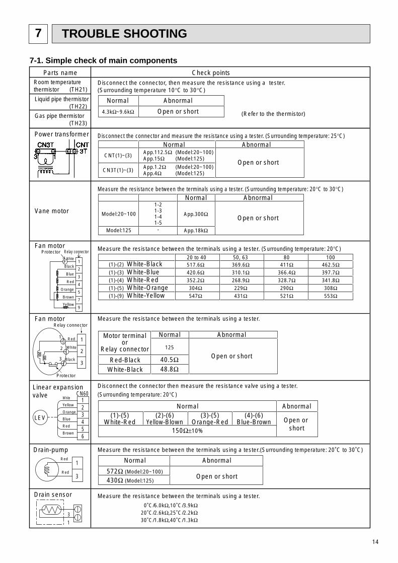
7 TROUBLE SHOOTING
7-1. Simple check of main components
Motor terminalor
Relay connector
Red-Black 40.5ΩWhite-Black 48.8Ω
11
22
33
Red
White
Black
Relay connector
Protector
Check points
Measure the resistance between the terminals using a tester.(Surrounding temperature: 20˚C to 30˚C)
Measure the resistance between the terminals using a tester. (Surrounding temperature: 20°C)
Measure the resistance between the terminals using a tester.
Parts nameRoom temperaturethermistor (TH21)
Disconnect the connector, then measure the resistance using a tester.(Surrounding temperature 10°C to 30°C)
(Refer to the thermistor)
Liquid pipe thermistor (TH22)
Gas pipe thermistor (TH23)
Normal
4.3kΩ~9.6kΩ
Abnormal
Open or short
Normal
572Ω (Model:20~100)
430Ω (Model:125)
Abnormal
Open or short
Normal(2)-(6)
Yellow-Blown(1)-(5)
White-Red(3)-(5)
Orange-Red(4)-(6)
Blue-Brown
Abnormal
Open or short
Measure the resistance between the terminals using a tester.
0˚C/6.0kΩ,10˚C/3.9kΩ20˚C/2.6kΩ,25˚C/2.2kΩ30˚C/1.8kΩ,40˚C/1.3kΩ
Linear expansionvalve
Drain sensor
Drain-pump
Disconnect the connector then measure the resistance valve using a tester.(Surrounding temperature: 20°C)
150Ω±10%
White
Yellow
Orange
Blue
Red
Brown
123456
CN60
1
3
Red
Red
1
3
LEV
517.6Ω(1)-(2) White-Black(1)-(3) White-Blue
369.6Ω420.6Ω 310.1Ω
(1)-(4) White-Red 352.2Ω 268.9Ω(1)-(5) White-Orange 304Ω 229Ω(1)-(9) White-Yellow 547Ω 431Ω
411Ω366.4Ω328.7Ω290Ω521Ω
462.5Ω397.7Ω341.8Ω308Ω553Ω
50, 63 80 10020 to 40
Measure the resistance between the terminals using a tester. (Surrounding temperature: 20°C to 30°C)
Vane motor
Fan motor
Fan motor
Disconnect the connector and measure the resistance using a tester. (Surrounding temperature: 25°C)
Normal
CNT(1)~(3)
CN3T(1)~(3)
App.112.5Ω (Model:20~100)App.15Ω (Model:125)
App.1.2Ω (Model:20~100)App.4Ω (Model:125)
Model:20~100
Abnormal
Open or short
Normal1-21-31-41-5-
App.300Ω
Model:125 App.18kΩ
Abnormal
Open or short
Power transformer
9
7
5
4
3
2
1P
Relay connectorProtectorWhite
Black
Blue
Red
Orange
Brown
Yellow
Normal
125
Abnormal
Open or short
14

0
10
20
30
40
50
-20 -10 0 10 20 30 40 50
< Thermistor for lower temperature >
Temperature (˚C)
Res
ista
nce
(KΩ
)
4 ø4
3
6
5
ø3
2 ø2
1 ø1
ø4
ø3
ø2
ø1
Controller board
Drive circuit
Connector(CN60)
DC12V
Brown
Red
Blue
Orange
Yellow
White
M
4
6
2
3
51
Blue
Brown
Yellow
OrangeRedWhite
Linear expansion valve
<Table of thermistor characteristics>
Table of thermistor resistance
Thermistor (piping temperature detection, room temperature detection)
Thermistor Ro = 15kΩ±3%B constant = 3480kΩ±2%
Thermistor R0=15kΩ ± 3%Fixed number of B=3480kΩ ± 2%
Rt=15exp 3480( )
0˚C 15kΩ10˚C 9.6kΩ20˚C 6.3kΩ25˚C 5.2kΩ30˚C 4.3kΩ40˚C 3.0kΩ
Linear expansion valve
Operation summary of the linear expansion valve.• Linear expansion valve open/close through stepping motor after receiving the pulse signal from the indoor controller board.• Valve position can be changed in proportion to the number of pulse signal.<Connection between the indoor controller board and the linear expasion valve>
1273+t
1273
15

Output(Phase)
Output
ø1
1
ON
ø2 ON
ø3 OFF
ø4 OFF
2
OFF
ON
ON
OFF
3
OFF
OFF
ON
ON
4
ON
OFF
OFF
ON
<Output pulse signal and the valve operation>
➁ Linear expansion valve operation
➂ Trouble shooting
D
A
E
B
C
Open
Extra tightning (80~100pulse)
Pulse number
1800 pulseOpening a valveall the way
Close
Val
ve p
ositi
on (
capa
city
)
654321
LED1kΩ
Symptom Check points
Operation circuit fail-ure of the microprocessor.
Disconnect the connector on the controller board, then con-nect LED for checking.
Pulse signal will be sent out for 10 seconds as soon as themain switch is turn on. If there is LED with lights on or lightsoff, it means the operation circuit is abnormal.
Countermeasures
Exchange the indoor con-troller board at drive circuitfailure.
Linear expansionvalve mechanism islocked.
Valve doesn´t closecompletely (thermis-tor leaking).
Wrong connection ofthe connector orcontact failure.
To check the linear expansion valve, operate the indoor unit infan mode and at the same time operate other indoor units incooling mode, then check the pipe temperature <liquid pipe
temperature> of the indoor unit by the out-door multi controller board operation moni-tor. During fan operation, linear expansionvalve is closed completely and if there aresome leaking, detecting temperature of thethermistor will go lower. If the detectedtemperature is much lower than the temper-ature indicated in the remote controller, it
means the valve is not closed all the way. It is not necessaryto exchange the linear expansion valve, if the leakage is smalland not making any trouble.
Thermistor(TH21)
Linearexpansionvalve
Motor will idle and make ticking noise when motor is operatedwhile the linear expansion valve is locked. This ticking soundis the sign of the abnormality.
Check the color of lead wire and missing terminal of the con-nector.
Exchange the linearexpansion vale.
Exchange the linearexpansion valve.
If large amount of refriger-ation is leaked, exchangethe linear expansion valve.
Disconnect the connectorat the controller board,then check the continuity.
Measure the resistance between the each coil (red-white,red-orange, brown-yellow, brown-blue) using a tester. It isnormal if the resistance is in the range of
Short or breakage ofthe motor coil of thelinear expansionvalve.
Closing a valve : 1 2 3 4 1Opening a valve : 4 3 2 1 4
The output pulse shifts in above order. 1. When linear expansion valve operation stops, all output phase
become OFF.2. At phase interruption or when phase does not shift in order,
motor does not rotate smoothly and motor will locks and vibrates.
When the switch is turned on, 2200 pulse closing valve signal willbe send till it goes to A point in order to define the valve posi-tion.
When the valve move smoothly, there is no noise or vibrationoccurring from the linear expansion valve : however, when thepulse number moves from E to A or when the valve is locked,more noise can be heard than normal situation.
Noise can be detected by placing the ear against the screw dri-ver handle while putting the screw driver to the linear expansionvalve.
150Ω 10%.
1:1800pulse at R410A outdoor unit. 2000pulse at the other outdoor unit.
1
16

17
7-2. FUNCTION OF DIP-SWITCH
1
2
3
4
5
6
7
8
9
10
1~6
1
2
3
1
2
3
4
1
2
3
4
5
6
7
8
9
10
Thermistor<Intake temperaturedetection>position
ON OFF
Filter crogging detection Provided Not provided
Filter life 2,500hr 100hr
Air intake Effective Not effective
Remote indication switching Thermostat ON signal indication Fan output indication
Humidifier control Always operated while the heat is ON Operated depends on the condition
Air flow st Low Extra low
Heat thermostat OFF Setting air flow Reset to SW1-7
Auto reset function Effective Not effective
Power ON/OFF Effective Not effective
Heat pump/Cooling only Cooling only Heat pump
Vane Available Not available
Vane swing function Available Not available
—
—
—
—
—
—
— —
— —
— —
—
— — —
— — —
—
—
—
—
— —
— —
— —
—
— — —
—
—
—
Heating
Demand
4K up Not effective
Not effective
Effective
Effective
ONOFF
1 2 3 4 5 6 7 8 9 10
1 2 3
1 2 3 4 5
ONOFF
<At delivery>
<At delivery>
<At delivery>SW4Unit
Selection
SW8
SW3FunctionSelection
FunctionSelection
SW2Capacity
codesetting
SW1Mode
Selection
Switch Pole Function
Built-in remote controller Indoor unit
Set while the unit is off.
<At delivery>Set for each capacity.
ONOFF
1 2 3 4 5 6 7 8 9 10
Model 20
ONOFF
1 2 3 4 5 6 7 8 9 10
Model 32
ONOFF
1 2 3 4 5 6 7 8 9 10
Model 25~100
ONOFF
1 2 3 4 5 6 7 8 9 10
Model 125
Model 20~100 Model 125
Set while the unit is off.
Set
Set while the unit is off.
while the unit is off.
Model 20~63 Model 80,100
Operation by switchRemarks
Note :The DipSW setting is effective during unit stopping ( remote controller OFF ) for SW1,2 and 3 commonly and the power souce is not required to reset.
1 2 3 4
ONOFF
<At delivery>
ONOFF
1 2 3
ONOFF
ONOFF
1 2 3 4 5 6
ONOFF
1 2 3 4 5 6
ONOFF
1 2 3 4 5 6
MODELS SW2 MODELS SW2 MODELS SW2
PLFY-P20VLMD-E
PLFY-P25VLMD-E
PLFY-P40VLMD-E
PLFY-P50VLMD-E
PLFY-P80VLMD-E
ONOFF
1 2 3 4 5 6
PLFY-P100VLMD-E
PLFY-P32VLMD-E
PLFY-P63VLMD-E
ONOFF
1 2 3 4 5 6
PLFY-P125VLMD-E
ONOFF
1 2 3 4 5 6
ONOFF
1 2 3 4 5 6
ONOFF
1 2 3 4 5 6
ONOFF
1 2 3 4 5 6

18
0
5
9
4
8 37
2
6
1
SW12
10
0
5
9
4
8 37
2
6
1
SW11
1
0
8
F
7
E
6
D 5C
4
B
3
A
2
9
1
SW14
0
5
9
4
8 37
2
6
1
SW120
5
9
4
8 37
2
6
1
SW11
0
8
F
7
E
6
D 5C
4
B
3
A
2
9
1
SW14
Operation by switchSwitch Pole Remarks
<At delivery>
<At delivery>
SW111st digitaddresssetting
SW122nd degitaddresssetting
Rot
ary
switc
h
SW14Connection
VoltageSelection
No.setting
Rot
ary
switc
h
Address setting should be done when networkremote controller (PAR-F25MA) is being used.
This is the switch to be used when the indoorunit is operated with R2 series outdoor unit asa set.
<At delivery>
2
1~4
SW5
SW7
If the unit is used at the 220V or 230V area,set
ON : 220, 230VOFF : 240V
the switch as ON.If the unit is used at the 240V, set the switchas OFF.
Address can be set while theunit is stopped.
Note:1
Note:1
Note:1
Note 1 : The DipSW setting is effective during unit stopping ( remote controller OFF ) for SW11,12,14 and 5.
ON
OFF
ON
OFF
ONOFF
1 2 3 4
Set while the unit is off.
<At delivery>ONOFF
1 2 3 4
<model: 20~100>

3
2
1
(Option)
(Standard)
SWC
123
(SWA)
0
5
9
4
8 37
26
1
SW12
10
0
5
9
4
8 37
2
6
1
SW11
1
0
8
F
7
E
6
D 5C
4
B
3
A
2
9
1
SW14
3
2
1
(Option)
(Standard)
0
5
9
4
8 37
2
6
1
SW120
5
9
4
8 37
2
6
1
SW11
0
8
F
7
E
6
D 5C
4
B
3
A
2
9
1
SW14
Address board
Address board
Address board
Address board
Operation by switchSwitch Pole Remarks
* As this switch is used by interlocking withSWC,refer to the item of SWC for detail
<At delivery>
<At delivery>
<At delivery>
<At delivery>
1~3SWA
Option
2SWCOption
SW111st digitaddresssetting
SW122nd degitaddresssetting
Rot
ary
switc
h
SW14Connection No.setting
Rot
ary
switc
h
When attach the optional high perfor-mance filter elements (filter casement)to the unit, be sure to attach it to theoption side in order to prevent the air-flow reducing.
Address setting should be done when networkremote controller (PAR-F25MA) is being used.
This is the switch to be used when the indoorunit is operated with R2 series outdoor unit asa set.
220V 240V
220V 240V
Address board
<At delivery>2
SW5VoltageSelection
If the unit is used at the 230V or 240V area,set the voltage to 240V.If the unit is used at the 220V, set the voltageto 220V.
Address can be set while theunit is stopped.
Note:1
Note:1
Note:2
Note:2
Note:2
Note 1:The DipSW setting is effective always after powering ( remote controller ON ) for SWA and SWC.2:The DipSW setting is effective during unit stopping ( remote controller OFF ) for SW11,12,14 and 5.
<model: 125>
19

20
8 DISASSEMBLY PROCEDURE
8-1.SERVICE PANEL and FILTER
OPERATING PROCEDURE
1. Removing the service panel (A) (Fig.1-1)
(1) Slide the service panel (A) in the direction of thearrow 1 while lifting it. ( depending on the localinstallation,the slide direction is reverse )
(2) After sliding, if it is opened in direction 2, the ser-vice panel (A) drops down as shown in Fig.1-2.
(3) Remove the service panel (A) from the two pins.(Be care-ful not to allow it to drop).
2. Removing the filter (Fig.1-2)
<Model 20~100>(1) Place fingers on the projection near the PUSH
mark on the filter, as shown in Fig. A. Removepanel frame with thumb, and press projectionswith other fingers to remove the hooks.
<Model 125>(1) Move the fixing claws (C) of the filter (B) in the
direction of the arrow 3.(Pull them while lifting them up.)
(2) After removing the fixing claws (C) of the filter (B)from the filter support plate (D), pull out the filter(B) in the direction of the arrow 4.
(Fig.1-1)
(Fig.1-2)
PHOTOS&ILLUSTRATIONS
(A) service panel
Inspectionpanel
Fig.A
Hooks
Press
(A)
(C)
(B)
(D)
<Model 20~100>
<Model 20~100>
<Model 125>
<Model 125>
Be careful removing heavy parts.

21
8-2.CONTROL BOX
OPERATING PROCEDURE
<Model 20~100>1. Remove the service panel and filter with the pro-
cedure explained in section 8-1.
2. Removing the control box cover (Fig.2-1).• Remove the fixing screws (one) of the control box
cover (A), and remove the cover.* At this stage, the following servicing is possible.1 Operation and check of the switches (listed below)
which are on the address board.• Rotary switches SW11, 12 Address setting• Rotary switch SW14 Branch port setting• Dip switch SW1 Function change 1• Dip switch SW2 Capacity setting• Dip switch SW3 Function change 2• Dip switch SW4 Model setting• Dip switch SW5 Option setting• Dip switch SW6 Model change • Dip switch SW7 Function change 3
2 Connection check and local connection of leadwires (listed below) which are connected to thecontrol box (B).• Power supply lead wire (Connected at the factory)• Drain pump lead wire (Connected at the factory)• LEV lead wire (Connected at the factory)• Panel vane motor lead wire (Connected locally)• Panel limit switch lead wire (Connected locally)• Drain pump trial operation connector
(Connected locally)• M-NET transmission lead wire (Connected at the factory)• MA remote controller transmission wire
(Connected at the factory)• Fan motor lead wire (Connected at the factory)• Intake air sensor lead wire (Connected at the factory)• Fluid piping sensor lead wire (Connected at the factory)• Gas piping sensor lead wire (Connected at the factory)
(• Humidifier lead wire)(• Auxiliary electric heater lead wire)
3 Control board exchange4 Condenser exchange5 Power supply transformer exchange6 Intake air sensor exchangeNote: The control PCB, capacitor and power trans-
former could fall off when removed.
(Fig.2-1)
(Photo.2-1)
PHOTOS&ILLUSTRATIONS
(A) Control box cover
Be careful removing heavy parts.
(B)

22
OPERATING PROCEDURE
<Model 125>1. Remove the service panel and filter with the pro-
cedure explained in section 8-1.
2. Removing the connector cover (A).• Remove the fixing screws (two) of the connector
cover (A), and remove the cover. (Fig.2-2)* At this stage, the following servicing is possible. (It
is even possible with the filter attached.)1 Operation and check of the switches (listed below)
which are on the address board (B).• Rotary switches SW11, 12 Address setting• Rotary switch SW14 Branch port setting• Dip switch SW1 Function change (main)• Slide switches SWA, C Airflow rate change
2 Connection check and local connection of leadwires (listed below) which are connected to thecontrol box (C).• Power supply lead wire (Connected at the factory)• Drain pump lead wire (Connected at the factory)• LEV lead wire (Connected at the factory)• Panel vane motor lead wire (Connected locally)• Panel limit switch lead wire (Connected locally)• Drain pump trial operation connector (Connected
locally)
3. Removing the control box (C)(1) Remove the fixing screws (three) of the filter fixed
plate (D). (Fig.2-3)(2) Also remove the fixing screws (three) of the con-
trol box cover (F) and remove it. (Fig.2-4)* At this stage, the following servicing is possible.1 Operation and check of the switches (listed below)
which are on the control board.• Dip switch SW2 Capacity code setting• Dip switch SW3 Function change (auxiliary)• Dip switch SW4 Model code settingAnd the address board exchange.
2 Connection check of the lead wires (listed below)which are connected to the control box• Power supply lead wire• Remote control communication lead wire• Fan motor lead wire• LEV lead wire• Drain pump lead wire• Drain sensor lead wire• Intake air sensor lead wire• Liquid piping sensor lead wire• Gas piping sensor lead wire• Power supply transformer lead wire• Address board lead wire• Panel vane motor lead wire• Panel limit switch lead wire
(Fig.2-2)
PHOTOS&ILLUSTRATIONS
(A)
(Fig.2-3)
(C)
(D)
(B)
(Fig.2-4)
Vane motor cover
(D)
(F)
(C)
Be careful removing heavy parts.

23
OPERATING PROCEDURE
3. Removing the control box (C)(3) If the control box (C) fixing screws (two) are
removed, the control box (C) is left hanging fromthe main unit by the falling prevention claws.If thecontrol box (C) is lifted the claws are released andthe control box (C) can be lowered down.Also, inorder to completely lower the control box (C), it isnecessary to remove the following lead wire con-nectors.
(4) Remove the control box earth wire (green/yellow)from the control box (C), and remove the control box(C).
* At this stage, the following servicing is possible.1 Control board exchange2 Condenser exchange3 Power supply transformer exchange
PHOTOS&ILLUSTRATIONS
Be careful removing heavy parts.
Controlbox
ControlBoard
• Power supply lead wire connector (3P : White)
• Drain pump lead wire connector(3P : White)
• LEV lead wire connector (6P : White) • Panel vane motor lead wire connector
(4P : White)• Panel limit switch lead wire connector
(2 : Green)
• Remote control communication leadwire connector (2P : Blue)
• Drain sensor lead wire connector (5P : Red)
• Intake air sensor lead wire connector(2P : Red)
• Liquid piping sensor lead wire connector(2P : White)
• Gas piping sensor lead wire connector(2P : Black)
• Fan motor lead wire connector ·····motor side connector (Black)
(C)
Falling prevention claw
Earth wire (green/yellow)
(Photo.2-2)
(Photo.2-3)
(Photo.2-4)
(Photo.2-5)

8-3.Fan and fan motor
24
OPERATING PROCEDURE
<Model 20~100>1. Remove the service panel and filter with the pro-
cedure explained in section 8-1.
2. Remove the two screws fixing the bell-mouth (A),and remove the bell-mouth A. (Fig. 3-1)
3. Remove the turbo fan mounting screw (one M8nut), and pull the turbo fan off the fan motor shaft.(Photograph 3-1)
Note: The turbo fan will come off the motor shaft whenthe mounting screw is removed, so take carenot to let turbo fan fall off when removing it.
4. Remove the lead wire retainer. (Two screws)(Photograph 3-3)
5. Disconnect the motor lead wire connector in thecontrol box.<In the case of model 80,100>
• Motor on the control box sideRemove the connector cover, and remove themotor lead wire connector.
• Motor on the opposite control box side(Photograph 3-1)(1) Remove the protection cover on the control box
side.(2) Remove the lead wire, pick the tab of the con-
nector, and push it into the motor side.
6. Remove the mounting nuts (four M5 nuts) fixingthe motor fixing leg and main body, and removethe fan motor together with the leg.(Photograph 3-3)
Note: The fan motor will come off the main body whenthe mounting screw is removed. It could fall off,so when removing, securely hold the fan motorand remove the mounting screws.
(Fig.3-1)
(Photo.3-1)
(Photo.3-3)
PHOTOS&ILLUSTRATIONS
Hooks
(A) Bell-mouth
Tab
Lead wire
Protectioncover
Push into the opposite control box side.
Control box side
Tab
Mounting nut
Mounting nut
Lead wire retainer
Be careful removing heavy parts.
(Photo.3-2)

25
OPERATING PROCEDURE
<Model 125>1. Remove the service panel and filter with the pro-
cedure explained in section 8-1.
2. Removing the filter fixed plate (A)Remove the fixing screws (three) of the filter fixedplate (A) and remove it. (Fig.1)
3. Removing the under-fan-casing (C)Push the fixing claws of the under-fan-casing (C) and remove it.
4. Removing the fan motor (D)Remove the lead wire connectors which are connect-ed to the fan motor (D), and remove the motor fix-tures (E) (two for each motor. Each motor is screweddown in two.)
Note: There are no falling prevention measures forthe fan motor. In order to prevent the fan motorfrom falling when it is removed, the work is tobe performed by two people. (It is dangerous todo this alone.)
5. Removing the sirocco fan (F)Remove the fan motor shaft fixing screw (one foreach fan), and remove the sirocco fan (F).
PHOTOS&ILLUSTRATIONS
Be careful removing heavy parts.
(A)
(Fig.3-2)
Fixing claws (Four for each casing)
(C)
Fixing screw(E)
(F)(D)
(Photo.3-4)
(Photo.3-3)

26
8-4.Thermistor <fluid piping temperature detection, gas piping temperature detection>
OPERATING PROCEDURE
<Model 20~100>1. Remove the service panel and filter with the pro-
cedure explained in section 8-1.2. Remove the decorative panel frame.
(1) Loosen the four stepped screws fixing the panel,and suspend the panel frame. (Fig. 4-1)
(2) When the panel frame is pressed (or pulled) in thelongitudinal direction, the stepped screws willcome out of the key holes provided on the panelframe, and the panel frame will come off.
3. Remove the bell-mouth with the procedureexplained in section 8-3 .
4. Remove the control box.(1) Remove the control box cover with the procedure
explained in section 8-2.(2) Disconnect the following lead wire connectors
from the control box. (Photograph 4-1)• Power supply lead wire (CND, 5P: red)• Drain pump lead wire (CNP, 3P: blue)• Drain sensor lead wire (CN31, 3P: white)• LEV lead wire (CN60, 6P: white)• Vane motor lead wire for panel (CN7V, 7P: white)• M-NET transmission lead wire (CN2M, 2P: blue)• MA remote controller transmission lead wire
(CN3A, 3P: blue)• Fan motor lead wire (CN90, 9P: blue)• Fluid piping temperature sensor lead wire (CN21, 2P: white)• Gas piping temperature sensor lead wire (CN29, 2P, black)
(3) Loosen the two screw fixing the control box, andremove the control box.
5. Remove the drain pan. (Photograph 4-2)(1) Remove the two drain pan fixing plates B.
(One screw/plate)(2) Remove the two drain pan fixing plates C.
(Three screws/plate)(3) Remove the side frame reinforcement plate.
(One screw)(4) Loosen the rubber plug on the drain pan's
drainage socket, and drain out all water from thedrain pan.Note: Before removing the rubber plug, prepare a
bucket, etc., so that the drainage will becaught. The desk or floor should be coveredwith a sheet, etc., so that water will not geton it inadvertently.
(5) Pull down the drain pan.Note: Pull the drain pan out gradually by shifting
the front and back to the left and right. Thedrain pan is made of styrofoam, so take carenot to break it.
6. Remove the thermistor from the thermistor holderon the copper piping (fluid piping ... thin piping,gas piping ... thick piping). (Photograph 4-3)Note: Each thermistor has a notch on the tube to
drain out any water condensed in the pipingtube. That section comes to the very bottom. Atrap is provided so that the water will drip intothe drain pan. Thus, when replacing the thermis-tor, always set the trap at the original position.
(Fig.4-1)
(Photo.4-1)
(Photo.4-2)
(Photo.4.3)
PHOTOS&ILLUSTRATIONS
Panel frameA
Control box
Fixing screw
Fixing plate B
Fixing plate CThermistor
Side frame reinforcement plate
Be careful removing heavy parts.

27
OPERATING PROCEDURE
<Model 125>1. Remove the service panel and filter with the pro-
cedure explained in section 8-1.
2. Remove the control box with the procedureexplained in section 8-2.
3. Removing the decorative panel frame (A)(1) Loosen the panel fixing stepped screws (four), and
the panel frame (A) is left hanging in midair.(Fig.4-2)
(2) The panel frame (A) is pushed (or pulled) in thelength direction, the stepped screws come out ofthe pear-shaped holes in the panel frame (A), andthe panel fame (A) can be removed.
4. Removing the drain pan (B)(1) Remove the screws which are fixing the drain pan
fixing plates (C) (two), and remove the plates.(2) Remove the drain pan falling prevention parts. (fix-
ing pin (D), fixing plate (E) and filter fixing plateinstallation plate (F).)
(3) Loosen the rubber plug (G) which in is the drainsocket of the drain pan (B), and drain the waterwhich is still in.
(4) Pull down the drain pan (B).
Note: Take it out by moving a little in all four direc-tions.The drain pan is made from poly-styrene.Handle it carefully so that it is notbroken.
5. Removing the partition plate (H).
Note: Take it out by moving a little in all four direc-tions. The partition plate is made from poly-styrene.Handle it carefully so that it is notbroken.
(Fig.4-2)
PHOTOS&ILLUSTRATIONS
(A)
Be careful removing heavy parts.
(C)
(E)
(F)
(B)(D)
(H)
(G)
(Photo.4-5)
(Photo.4-4)

28
OPERATING PROCEDURE
6. Removing the thermistorsRemove the thermistors (K and L) from the thermistor holders (I and J) which are installed on the steel pip-ing (liquid piping ····· fine piping, gas piping ····· thickpiping).
PHOTOS&ILLUSTRATIONS
Be careful removing heavy parts.
(B)
(H)
(J) (L)
(K)
( I )
(Photo.4-6)
(Photo.4-8)
(Photo.4-7)

29
8-5.THERMISTOR (Intake air temperature detection)
OPERATING PROCEDURE
<Model 125>1. Remove the service panel and filter with the pro-
cedure explained in section 8-1.
2. Remove the control box cover with the procedureup to 3. (2) of 8-2.
3. Removing the thermistor(1) Remove the fixing screw (one) of the thermistor
installation plate (A), and pull down the thermistorwith installation plate.
(2) Remove the thermistor lead wire which is connect-ed to the control board.
PHOTOS&ILLUSTRATIONS
Be careful removing heavy parts.
(A)
(Photo.5-1)

30
8-6.DRAIN PUMP and DRAIN SENSOR
OPERATING PROCEDURE
<Model 20~100>1. Remove the service panel and filter with the pro-
cedure explained in section 8-1.
2. Remove the decorative panel frame with the pro-cedure explained in section 8-4.
3. Remove the bell-mouth with the procedureexplained in section 8-3.
4. Remove the control box with the procedureexplained in section 8-4.
5. Remove the drain pan with the procedureexplained in section 8-4.
6. Remove the binding band on the drain hose con-nected to the drain pump.
7. The drain pump and drain sensor, fixed to thecover, are fixed to the main unit. Remove the twofixing screws and remove. (Photograph 6-1)
<Model 125>1. Remove the service panel and filter with the pro-
cedure explained in section 8-1.
2. Remove the control box with the procedureexplained in section 8-2.
3. Remove the decorative panel frame,drain pan andpartition plate with the procedure up to 3.~5.of8-4.
4. Removing the drain pump(A)(1) Cut the drain hose fixing binder (C), which hose is
connected to the drain pump (A)(2) Remove the fixing screws (two) which fix the
bracket (E) to the unit fixtures (D), and remove thedrain pump (A) from the main unit.(Photograph 6-2)
(Photo.6-1)
PHOTOS&ILLUSTRATIONS
Fixing screw
Be careful removing heavy parts.
(D)(A) (E)
(C)(B)(Photo.6-2)

31
8-7.LEV and HEAT EXCHANGER
OPERATING PROCEDURE
<Model 20~100>1. Remove the service panel and filter with the pro-
cedure explained in section 8-1.
2. Remove the decorative panel frame with the pro-cedure explained in section 8-4.
3. Remove the bell-mouth with the procedureexplained in section 8-3.
4. Remove the control box with the procedureexplained in section 8-4.
5. Remove the drain pan with the procedureexplained in section 8-4.
6. Remove the LEV drive motor with a double span-ner. (Photograph 7-1)
7. Remove the fluid piping connection flare, gas pip-ing connection flare, and then lower the unit bodyto remove the heat exchanger.(Photographs 7-2, 7-3)(1) Remove the two heat exchanger support plates A.
(One screw/plate)(2) Remove the heat exchanger support plate B. (Two
screws)(3) Remove the piping fixing plate C. (Two screws)(4) Slide the heat exchanger in the direction opposite
the piping, and remove it.
Note 1: Cover the control box, motor, drain pumpand LEV with cloth, etc., to protect themin case water should come in contactwhen washing the drain pan and heatexchanger.
Note 2: Do not drain the water used to clean thedrain pan and heat exchanger with therain pump. Drain it separately.
(Photo.7-1)
PHOTOS&ILLUSTRATIONS
(Photo.7-2)
(Photo.7-3)
LEVDrive motor
Heat exchanger support plate A
Piping fixing plate C
Heat exchanger support plate B
Be careful removing heavy parts.

32
OPERATING PROCEDURE
<Model 125>1. Remove the service panel and filter with the pro-
cedure explained in section 8-1.
2. Remove the control box with the procedureexplained in section 8-2.
3. Remove the decorative panel frame, drain pan andpartition plate with the procedure up to 3.~5.of 8-4.
4. Removing the LEV driving motor (B)Remove the LEV driving motor (B) with a doublespanner.
5. Removing the heat exchanger (C)After removing the liquid piping connection flare (D)and gas piping connection flare (E), lower the unitand remove the heat exchanger (C).
(1) Remove the non-piping side frame (F).(Secured by seven screws.)
(2) Remove the side frames (G and H).(secured by seven screws each.)
(3) Remove the piping side frame (I) and the pipingfixing plate (J).(The frame (I) is secured by three screws and the piping fixing plate (J) by two screws.)
(4) Slide the heat exchanger (C) towards the non-pip-ing side, and remove it from the ceiling (K) hang-ing holes.
PHOTOS&ILLUSTRATIONS
Be careful removing heavy parts.
(J)
(B)
(H)( I )(E)
(A)
(F)(C)(K)(G)(D)
(Photo.7-4)
(Photo.7-5)
(Photo.7-6)

33
8-8.Vane motor
OPERATING PROCEDURE
1. Remove the metal cover. (Three screws)(Photograph 8-1)
2. Remove the vane motor cover.The vane motor cover can be removed by pushingit up with fingers.
3. Remove the two motor mounting screws.(Photograph 8-2)
(Photo.8-1)
PHOTOS&ILLUSTRATIONS
(Photo.8-2)
Fixing screw Metal coverVane motor cover
Fixing screw Vane motor Fixing screw
Be careful removing heavy parts.

HEAD OFFICE: MITSUBISHI DENKI BLDG., 2-2-3, MARUNOUCHI, CHIYODA-KU, TOKYO 100-8310, JAPAN
Issued in June 2004 MEE04K240Printed in Japan
New publication, effective June 2004Specifications subject to change without notice